EP1238636A1 - External fixation device with identification means - Google Patents
External fixation device with identification means Download PDFInfo
- Publication number
- EP1238636A1 EP1238636A1 EP01830149A EP01830149A EP1238636A1 EP 1238636 A1 EP1238636 A1 EP 1238636A1 EP 01830149 A EP01830149 A EP 01830149A EP 01830149 A EP01830149 A EP 01830149A EP 1238636 A1 EP1238636 A1 EP 1238636A1
- Authority
- EP
- European Patent Office
- Prior art keywords
- fixation device
- plate
- recess
- central body
- radiation
- Prior art date
- Legal status (The legal status is an assumption and is not a legal conclusion. Google has not performed a legal analysis and makes no representation as to the accuracy of the status listed.)
- Granted
Links
- 239000000463 material Substances 0.000 claims description 11
- 239000004033 plastic Substances 0.000 claims description 10
- 229920003023 plastic Polymers 0.000 claims description 10
- 208000010392 Bone Fractures Diseases 0.000 claims description 9
- 210000000988 bone and bone Anatomy 0.000 claims description 8
- 229910000838 Al alloy Inorganic materials 0.000 claims description 4
- 210000001699 lower leg Anatomy 0.000 description 4
- 238000004519 manufacturing process Methods 0.000 description 4
- 230000000007 visual effect Effects 0.000 description 4
- 239000000956 alloy Substances 0.000 description 2
- 239000000975 dye Substances 0.000 description 2
- 239000000203 mixture Substances 0.000 description 2
- 230000000399 orthopedic effect Effects 0.000 description 2
- 238000001356 surgical procedure Methods 0.000 description 2
- FGRBYDKOBBBPOI-UHFFFAOYSA-N 10,10-dioxo-2-[4-(N-phenylanilino)phenyl]thioxanthen-9-one Chemical compound O=C1c2ccccc2S(=O)(=O)c2ccc(cc12)-c1ccc(cc1)N(c1ccccc1)c1ccccc1 FGRBYDKOBBBPOI-UHFFFAOYSA-N 0.000 description 1
- 229920000049 Carbon (fiber) Polymers 0.000 description 1
- 210000003423 ankle Anatomy 0.000 description 1
- 230000002238 attenuated effect Effects 0.000 description 1
- 230000004323 axial length Effects 0.000 description 1
- 239000004917 carbon fiber Substances 0.000 description 1
- 239000003086 colorant Substances 0.000 description 1
- 238000010276 construction Methods 0.000 description 1
- 238000007796 conventional method Methods 0.000 description 1
- 230000007423 decrease Effects 0.000 description 1
- 230000000694 effects Effects 0.000 description 1
- 239000012634 fragment Substances 0.000 description 1
- 210000002758 humerus Anatomy 0.000 description 1
- 238000001746 injection moulding Methods 0.000 description 1
- 230000014759 maintenance of location Effects 0.000 description 1
- 239000011159 matrix material Substances 0.000 description 1
- 238000000034 method Methods 0.000 description 1
- 238000012986 modification Methods 0.000 description 1
- 230000004048 modification Effects 0.000 description 1
- 238000000465 moulding Methods 0.000 description 1
- 229920001643 poly(ether ketone) Polymers 0.000 description 1
- 238000011084 recovery Methods 0.000 description 1
- 238000009877 rendering Methods 0.000 description 1
- 230000000087 stabilizing effect Effects 0.000 description 1
- 210000002303 tibia Anatomy 0.000 description 1
- 210000000689 upper leg Anatomy 0.000 description 1
- 210000000707 wrist Anatomy 0.000 description 1
Images


Classifications
-
- A—HUMAN NECESSITIES
- A61—MEDICAL OR VETERINARY SCIENCE; HYGIENE
- A61B—DIAGNOSIS; SURGERY; IDENTIFICATION
- A61B17/00—Surgical instruments, devices or methods, e.g. tourniquets
- A61B17/56—Surgical instruments or methods for treatment of bones or joints; Devices specially adapted therefor
- A61B17/58—Surgical instruments or methods for treatment of bones or joints; Devices specially adapted therefor for osteosynthesis, e.g. bone plates, screws, setting implements or the like
- A61B17/60—Surgical instruments or methods for treatment of bones or joints; Devices specially adapted therefor for osteosynthesis, e.g. bone plates, screws, setting implements or the like for external osteosynthesis, e.g. distractors, contractors
- A61B17/64—Devices extending alongside the bones to be positioned
- A61B17/6458—Devices extending alongside the bones to be positioned with pin-clamps fixed at ends of connecting element
-
- A—HUMAN NECESSITIES
- A61—MEDICAL OR VETERINARY SCIENCE; HYGIENE
- A61B—DIAGNOSIS; SURGERY; IDENTIFICATION
- A61B90/00—Instruments, implements or accessories specially adapted for surgery or diagnosis and not covered by any of the groups A61B1/00 - A61B50/00, e.g. for luxation treatment or for protecting wound edges
- A61B90/90—Identification means for patients or instruments, e.g. tags
- A61B90/92—Identification means for patients or instruments, e.g. tags coded with colour
-
- A—HUMAN NECESSITIES
- A61—MEDICAL OR VETERINARY SCIENCE; HYGIENE
- A61B—DIAGNOSIS; SURGERY; IDENTIFICATION
- A61B90/00—Instruments, implements or accessories specially adapted for surgery or diagnosis and not covered by any of the groups A61B1/00 - A61B50/00, e.g. for luxation treatment or for protecting wound edges
- A61B90/90—Identification means for patients or instruments, e.g. tags
- A61B90/94—Identification means for patients or instruments, e.g. tags coded with symbols, e.g. text
-
- A—HUMAN NECESSITIES
- A61—MEDICAL OR VETERINARY SCIENCE; HYGIENE
- A61B—DIAGNOSIS; SURGERY; IDENTIFICATION
- A61B90/00—Instruments, implements or accessories specially adapted for surgery or diagnosis and not covered by any of the groups A61B1/00 - A61B50/00, e.g. for luxation treatment or for protecting wound edges
- A61B90/90—Identification means for patients or instruments, e.g. tags
Definitions
- This invention broadly relates to an external fixation device for reducing bone fractures in orthopedic surgery.
- the invention relates to an external fixation device having a carrying structure made up of interconnected elements, specifically a structure comprising an extendible central body and oppositely located clamps for bone screws, which clamps are articulated to respective ends of the central body by means of ball joints.
- Such external fixation devices comprise a central body of substantially cylindrical shape, which is extendible axially and has bone screw clamps articulated to its opposed ends by means of ball joints.
- the clamps are connected to rod-like bone screws which have been implanted into the cortex of the broken bone, from either sides of the fracture.
- two or three screws are adequate to guarantee a broken bone.
- fixation devices to cope with different types of fractures and traumatisms are normally available from their suppliers.
- fixation devices for the tibia and the femur fixation devices for the humerus, fixation devices for joints such as the ankle and the elbow, and fixation devices for the wrist are available.
- a well-recognized demand in this technical field is that of providing the device with visually identifiable means which should assist the orthopedist in his/her work of placing the device to a fractured part of an individual's skeleton, and later, which should give a visual indication, even approximate, of the mutual positions of the working parts of the fixation device.
- fixation device with decorative elements effective to enhance the outward appearance of the fixation device, for the orthopedist's sake as well as the patient's sake.
- fixation devices come short of filling the above demands in that they are made of a homogeneous structure, usually of a plastic material transparent to X-radiation to permit unobstructed radiographs of the fractured region.
- a plastic material transparent to X-radiation to permit unobstructed radiographs of the fractured region.
- the outward appearance of such fixation devices is often so unsightly that they are hidden under some covering.
- any improvements in the direction of filling the above demands are restrained by the relatively high manufacturing cost of fixation devices, especially those incorporating one or more elements made up of a material transparent to X-radiation, and by the need to maintain a desired transparency to X-radiation and biocompatibility of the used materials.
- the underlying technical problem of this invention is to provide an external fixation device for stabilizing bone fractures, with structural and functional features appropriate to fill at least one of the aforesaid demands.
- a unilateral axial external fixation device for reducing bone fractures in orthopedic surgery is shown generally at 1.
- the fixation device 1 has a carrying structure made up of interconnected elements, which structure comprises a rod-like central body 2 having a longitudinal axis x-x, and having opposite ends 3, 4 which are articulated to respective clamps 5, 6 for bone screws.
- the rod-like central body 2 and clamps 5, 6 are preferably made up of a material transparent to X-radiation, such as a polyetherketone plastics matrix, known as "Peek", suitably reinforced with a predetermined amount of carbon fibers to confer a suitable rigidity.
- a material transparent to X-radiation such as a polyetherketone plastics matrix, known as "Peek"
- Peek suitably reinforced with a predetermined amount of carbon fibers to confer a suitable rigidity.
- the rod-like central body 2 is axially extendible and comprises a first part 8 and a second part 9 slidably coupled to each other together to allow the central body 2 to be extended telescopically.
- Said parts 8, 9 comprise each a first portion 8a, 9a, of elongate shape, which is formed integrally with a second end portion 8b, 9b being substantially cylindrical in shape and shorter.
- each part 8, 9 is L-shaped in side view.
- the elongate portions 8a, 9a are slidably coupled to each other by means of a driving groove 7, formed longitudinally in the portion 8a, and a corresponding slide 7a formed longitudinally in the other portion 9a.
- the fixation device 1 further comprises conventional means for stopping said parts 8 and 9 in their sliding movement.
- This stopping means consists of a set screw 11 extending perpendicularly to the longitudinal axis x-x and having a threaded end portion screwed in a conventional manner in a threaded hole (not shown) provided in the slide 7a.
- portion 8a of the part 8 is formed with a clearance slot 10 which spans longitudinally most of said portion to let the screw 11 go through it preferably with a smooth section of its shank for easier sliding movement of the portions 8 and 9 one on the other.
- the screw 11 is an Allen screw, for more convenient operation by a corresponding wrench.
- the extension of the rod-like central body 2 of the fixation device 1 can be adjusted by loosening and tightening the screw 11, depending from the dimensions of the broken bone. No relative rotation is instead allowed of the parts 8 and 9 about the longitudinal axis x-x of the rod-like central body 2, due to the C- and T-shaped cross-sections of the driving groove and the slide.
- the opposed ends 3, 4 of the rod-like central body 2 are articulated to the respective clamps 5, 6 for bone screws by means of ball joints.
- each ball-and-socket joint 16 comprises a ball head with a shank, the ball head being fitted into a socket formed in each clamp 5, 6, and the shank being fitted, in a conventional manner, in a corresponding seat in each of the ends 3, 4 of the rod-like central body 2.
- the shank is held in its seat by a conventional releasable retention means, e.g. a pin 17.
- This pin 17 also provides a reference base for a dynamization compressor, such as that disclosed in European Patent Application No. 0 734 233.
- the clamps 5 and 6 comprise each a main body 20, in which the socket for receiving the ball head of the ball-and-socket joint 16 is formed.
- a sideplate 26 is removably associated with the main body 20 for tightening the clamp onto bone screws 22, in the example three screws 22 lying in a plane parallel to the plane containing the axis x-x and being placed a predetermined distance away therefrom.
- the fixation device 1 also comprises locking means 23 of the ball-and-socket joint 16 in a selected angular position.
- This locking means 23 comprises of a drive rotary shaft acting in the main body 20 and having a handling end 24 that protrudes from said main body 20.
- the end 24 has a radial projection 24a for more convenient manipulation of the locking means 23.
- the fixation device 1 has an oval plate 27 of a given thickness releasably attached to the rod-like central body 2.
- the plate 27 is lodged into a corresponding seat consisting of a recess 28 formed on the surface of the elongate portion 8a of the rod-like central body 2.
- the depth of the recess 28 is substantially equal to the thickness of the plate 27.
- the plate 27 is made releasably fast with the elongate portion 8a, by fitting two opposed pins 31 integrally formed on the underside of the plate 27 into corresponding blind holes 30 formed in the bottom 29 of the recess 28.
- the plate 27 is secured in the recess 28, but is easily removed for replacement.
- the plate 27 is formed from a plastic material that is transparent to X-radiation and a contrasting color with that of the rod-like body 2, so that the chromatic effect will distinguish the fixation device 1 of this invention.
- this plate could be made of another plastics or aluminum alloy material producing low interference on X-radiation.
- the plastic plate 27 is formed by conventional processes such as injection molding, and can be either bulk-stained or post-molding dyed by conventional methods.
- the plate 27 is made with a thin thickness, preferably comprised in the range of 0.5 to 1.5 mm, so that the plate will not appreciably interfere on a standard X-raying apparatus as a result of any opaque material to X-radiation entering its composition and/or because of the dyestuff.
- the plate 27 can bear, on its outer surface 27a exposed to view, such captions, insignia, logos and/or graphic compositions as may be the manufacturer's choice and/or demanded by the user, for example, in order to distinguish the fixation device 1 according to specific taste and personal preference.
- the visible outer surface 27a of the plate 27 is advantageously knurled to render more safe the grip and the manipulation of the fixation device 1.
- an external fixation device of the unilateral axial type is shown generally at 40.
- the fixation device 40 has two plates 41 releasably attached to opposed sides of each clamp 5, 6, two plates 42 and 60 releasably attached to part 8 of the rod-like central body 2, and one plate 43 releasably attached to part 9 of the central body 2.
- each plate 41 is placed close to the locking means 23 of the ball-and-socket joint 16 and extends between a substantially central location on one of the clamps 5, 6 and the free end thereof, so as to provide a visual indication of the movement of the radial projection 24a on the handling end 24 of said locking means 23.
- each plate 41 situates in the background from the arcuate path travelled by the radial projection 24a as the end 24 of the locking means 23 is manipulated.
- each plate 41 has a substantially comma-shaped contour with a cross-section that decreases gradually toward a central position of one of the clamps 5, 6.
- each plate 41 advantageously provides the orthopedist with a visual indication of the rotation of the handling end 24, as well as a visual indication, albeit approximate, of the operational state of the locking means 23.
- a radial projection 24a aligned to regions of increasing cross-section of the plate 41 as a result of the handling end 24 having been manipulated advantageously provides the orthopedist with an indication of increased effectiveness of the ball-and-socket joint 16 locking.
- Each plate 41 is lodged in a respective seat in one of the clamps 5, 6.
- This seat consists of a recess 44 having preferably a depth from the surface that is substantially equal to the thickness of a plate 41.
- Each plate 41 is releasably fast to one of the clamps 5, 6 by fitting a pin 46a, integrally formed on the underside of the plate 41 into a corresponding blind hole 46 formed in the bottom 45 of a recess 44.
- the plate 42 consists of an elongate bar extending lengthwise on the elongate portion 8a of the rod-like central body 2, laterally of the slot 10, to nearly span its full axial length.
- the plate 42 is lodged in a corresponding seat provided in the elongate portion 8a of the rod-like central body 2.
- This seat consists of a recess 47 having preferably a depth from the surface that is substantially equal to the thickness of the plate 42.
- the plate 42 is releasably fast to the elongate portion 8a by fitting two opposed pins 50, integrally formed on the underside of the plate 42 into respective blind holes 49 provided in the bottom 48 of the recess 47.
- the plate 60 is circular in shape and locates centrally close to one end of the elongate portion 8a of the rod-like central body 2.
- the releasable attachment of the plate 60 to the elongate portion 8a is performed in a similar way as the plate 42, and therefore it will not be further described.
- the plate 43 consists of an elongate bar extending lengthwise on the slide 7a formed in the portion 9a of the rod-like central body 2.
- the plate 43 is lodged in a corresponding seat provided in said slide 7a.
- This seat consists of a recess 51 having preferably a depth from the surface that is substantially equal to the thickness of the plate 43.
- the plate 43 is releasably fast to the slide 7a by fitting two opposed pins 54 integrally formed on the underside of the plate 43 in respective blind holes 53 provided in the bottom 52 of the recess 51.
- the plate 43 has a visible outer surface 43b impressed with a calibrated scale 43a that advantageously provides the orthopedist with a measure of the extension of the rod-like central body 2 achieved by a sliding movement of the parts 8 and 9.
- the plates 41, 42, 43 and 60 just described are advantageously made of a plastic material transparent to X-radiation and colored to create contrast with the color of the fixation device parts bearing them.
- these plates could be made of any other plastics or aluminum alloy material producing low interference on X-radiation.
- the plates 41, 42, 43 and 60 are made with a thin thickness preferably comprised in the range of 0.5 to 1.5 mm, so that they will not interfere appreciably on standard X-ray equipment.
- the fixation device of this invention does solve the technical problem and offers a number of advantages, among which the foremost is its being highly versatile and quite simple to manufacture.
- any decorative element can be provided on the fixation device structure by exchanging plates of contrasting colors, rendering the plates interchangeable.
- fixation device Another advantage of the fixation device according to the invention is that the plates can be made of the same material transparent to X-radiation as that of the other components of the device, so that the plates would not interfere on standard X-ray equipment, or would only interfere to a reduced extent by reason of the dyestuff they incorporate.
- a further advantage of the fixation device according to the invention is that of its high level of bio-compatibility which is not altered by the presence of contrasting colour plates thereon.
- fixation device no less important advantage of the fixation device according to the invention, is that the provision of decorating plates is of minor relevance to the manufacturing cost of the device. Consequently, the manufacturing cost of latter is fully comparable with that of similar fixation devices of the state of the art.
Abstract
Description
- This invention broadly relates to an external fixation device for reducing bone fractures in orthopedic surgery.
- More particularly, the invention relates to an external fixation device having a carrying structure made up of interconnected elements, specifically a structure comprising an extendible central body and oppositely located clamps for bone screws, which clamps are articulated to respective ends of the central body by means of ball joints.
- In this specific technical field, external fixation devices have long been employed to foster recovery of bone fractures by holding the bone fragments firmly in place.
- Such external fixation devices comprise a central body of substantially cylindrical shape, which is extendible axially and has bone screw clamps articulated to its opposed ends by means of ball joints. The clamps are connected to rod-like bone screws which have been implanted into the cortex of the broken bone, from either sides of the fracture. Usually, two or three screws are adequate to guarantee a broken bone.
- A variety of fixation devices to cope with different types of fractures and traumatisms are normally available from their suppliers.
- Thus, fixation devices for the tibia and the femur, fixation devices for the humerus, fixation devices for joints such as the ankle and the elbow, and fixation devices for the wrist are available.
- A well-recognized demand in this technical field is that of providing the device with visually identifiable means which should assist the orthopedist in his/her work of placing the device to a fractured part of an individual's skeleton, and later, which should give a visual indication, even approximate, of the mutual positions of the working parts of the fixation device.
- Another demand from this field is that of providing the fixation device with decorative elements effective to enhance the outward appearance of the fixation device, for the orthopedist's sake as well as the patient's sake.
- Unfortunately, state-of-art fixation devices come short of filling the above demands in that they are made of a homogeneous structure, usually of a plastic material transparent to X-radiation to permit unobstructed radiographs of the fractured region. Thus, the outward appearance of such fixation devices is often so unsightly that they are hidden under some covering.
- Furthermore, any improvements in the direction of filling the above demands are restrained by the relatively high manufacturing cost of fixation devices, especially those incorporating one or more elements made up of a material transparent to X-radiation, and by the need to maintain a desired transparency to X-radiation and biocompatibility of the used materials.
- The underlying technical problem of this invention is to provide an external fixation device for stabilizing bone fractures, with structural and functional features appropriate to fill at least one of the aforesaid demands.
- The technical problem is solved according to the invention by an external fixation device as previously indicated and as defined in the characterizing portion of
Claim 1 and followings. - The features and advantages of the external fixation device according to the invention will be apparent from the following description of embodiments thereof, given by way of non-limitative examples with reference to the accompanying drawings.
- In the drawings:
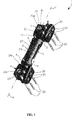
- Figure 1 is a perspective view of a unilateral external fixation device according to this invention, shown in its closed setting;
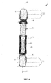
- Figure 2 is a perspective view of the fixation device in Figure 1, shown in its open setting;
- Figure 3 is an exploded perspective view of the fixation device shown in Figure 1;
- Figures 4 to 6 are side views, taken under different angles, of the fixation device shown in Figure 2;
- Figure 7 is an unilateral axial type of external fixation device according to another embodiment of this invention;
- Figures 7a and 7b are side views, taken under different angles, of the fixation device shown in Figure 7;
- Figure 8 is a perspective view of a detail of the fixation device shown in Figure 8;
- Figure 9 is an exploded perspective view of the detail shown in Figure 8;
- Figure 10 is a perspective view of another detail of the fixation device shown in Figure 7; and
- Figure 11 is an exploded perspective view of the detail shown in Figure 10.
-
- With reference to annexed Figures 1 to 6, a unilateral axial external fixation device for reducing bone fractures in orthopedic surgery, according to this invention, is shown generally at 1.
- The
fixation device 1 has a carrying structure made up of interconnected elements, which structure comprises a rod-likecentral body 2 having a longitudinal axis x-x, and having opposite ends 3, 4 which are articulated torespective clamps - The rod-like
central body 2 andclamps - The rod-like
central body 2 is axially extendible and comprises afirst part 8 and asecond part 9 slidably coupled to each other together to allow thecentral body 2 to be extended telescopically. - Said
parts first portion second end portion part - The
elongate portions groove 7, formed longitudinally in theportion 8a, and acorresponding slide 7a formed longitudinally in theother portion 9a. - The
fixation device 1 further comprises conventional means for stopping saidparts set screw 11 extending perpendicularly to the longitudinal axis x-x and having a threaded end portion screwed in a conventional manner in a threaded hole (not shown) provided in theslide 7a. - In addition, the
portion 8a of thepart 8 is formed with aclearance slot 10 which spans longitudinally most of said portion to let thescrew 11 go through it preferably with a smooth section of its shank for easier sliding movement of theportions - The
screw 11 is an Allen screw, for more convenient operation by a corresponding wrench. - The extension of the rod-like
central body 2 of thefixation device 1 can be adjusted by loosening and tightening thescrew 11, depending from the dimensions of the broken bone. No relative rotation is instead allowed of theparts central body 2, due to the C- and T-shaped cross-sections of the driving groove and the slide. - In the setting of minimum bulk of the rod-like
central body 2, theelongate portions parts cylindrical end portion - The opposed ends 3, 4 of the rod-like
central body 2 are articulated to therespective clamps - These ball joints are known per se, and are ball-and-
socket joints 16 mounted to eachclamp - In particular, each ball-and-
socket joint 16 comprises a ball head with a shank, the ball head being fitted into a socket formed in eachclamp central body 2. - The shank is held in its seat by a conventional releasable retention means, e.g. a
pin 17. Thispin 17 also provides a reference base for a dynamization compressor, such as that disclosed in European Patent Application No. 0 734 233. - The
clamps main body 20, in which the socket for receiving the ball head of the ball-and-socket joint 16 is formed. - A
sideplate 26 is removably associated with themain body 20 for tightening the clamp ontobone screws 22, in the example threescrews 22 lying in a plane parallel to the plane containing the axis x-x and being placed a predetermined distance away therefrom. - The
fixation device 1 also comprises locking means 23 of the ball-and-socket joint 16 in a selected angular position. This locking means 23 comprises of a drive rotary shaft acting in themain body 20 and having ahandling end 24 that protrudes from saidmain body 20. - The
end 24 has aradial projection 24a for more convenient manipulation of the locking means 23. - The structural and operational characteristics of the
clamps sideplate 26, and of the releasable connection of the latter to themain body 20 are conventional, and will not be further discussed. - In accordance with the invention, the
fixation device 1 has anoval plate 27 of a given thickness releasably attached to the rod-likecentral body 2. - In particular, the
plate 27 is lodged into a corresponding seat consisting of arecess 28 formed on the surface of theelongate portion 8a of the rod-likecentral body 2. Preferably, the depth of therecess 28 is substantially equal to the thickness of theplate 27. - The
plate 27 is made releasably fast with theelongate portion 8a, by fitting twoopposed pins 31 integrally formed on the underside of theplate 27 into correspondingblind holes 30 formed in thebottom 29 of therecess 28. - Thus, the
plate 27 is secured in therecess 28, but is easily removed for replacement. - Advantageously, the
plate 27 is formed from a plastic material that is transparent to X-radiation and a contrasting color with that of the rod-like body 2, so that the chromatic effect will distinguish thefixation device 1 of this invention. - However, this plate could be made of another plastics or aluminum alloy material producing low interference on X-radiation.
- The
plastic plate 27 is formed by conventional processes such as injection molding, and can be either bulk-stained or post-molding dyed by conventional methods. - Preferably, the
plate 27 is made with a thin thickness, preferably comprised in the range of 0.5 to 1.5 mm, so that the plate will not appreciably interfere on a standard X-raying apparatus as a result of any opaque material to X-radiation entering its composition and/or because of the dyestuff. - Also, the
plate 27 can bear, on itsouter surface 27a exposed to view, such captions, insignia, logos and/or graphic compositions as may be the manufacturer's choice and/or demanded by the user, for example, in order to distinguish thefixation device 1 according to specific taste and personal preference. - In this embodiment, the visible
outer surface 27a of theplate 27 is advantageously knurled to render more safe the grip and the manipulation of thefixation device 1. - Making now reference to Figures 7 to 11, an external fixation device of the unilateral axial type, according to another embodiment of the invention, is shown generally at 40.
- In all these Figures, elements having the same construction as or functionally equivalent to those of the
fixation device 1 shown in Figures 1 to 6 are denoted by the same reference numerals. - The
fixation device 40 has twoplates 41 releasably attached to opposed sides of eachclamp plates part 8 of the rod-likecentral body 2, and oneplate 43 releasably attached topart 9 of thecentral body 2. - In particular, each
plate 41 is placed close to the locking means 23 of the ball-and-socket joint 16 and extends between a substantially central location on one of theclamps radial projection 24a on the handlingend 24 of said locking means 23. - In other words, each
plate 41 situates in the background from the arcuate path travelled by theradial projection 24a as theend 24 of the locking means 23 is manipulated. - In practice, each
plate 41 has a substantially comma-shaped contour with a cross-section that decreases gradually toward a central position of one of theclamps - Thus, each
plate 41 advantageously provides the orthopedist with a visual indication of the rotation of the handlingend 24, as well as a visual indication, albeit approximate, of the operational state of the locking means 23. - For example, a
radial projection 24a aligned to regions of increasing cross-section of theplate 41 as a result of the handlingend 24 having been manipulated, advantageously provides the orthopedist with an indication of increased effectiveness of the ball-and-socket joint 16 locking. - Each
plate 41 is lodged in a respective seat in one of theclamps recess 44 having preferably a depth from the surface that is substantially equal to the thickness of aplate 41. - Each
plate 41 is releasably fast to one of theclamps pin 46a, integrally formed on the underside of theplate 41 into a correspondingblind hole 46 formed in the bottom 45 of arecess 44. - The
plate 42 consists of an elongate bar extending lengthwise on theelongate portion 8a of the rod-likecentral body 2, laterally of theslot 10, to nearly span its full axial length. - In practice, the
plate 42 is lodged in a corresponding seat provided in theelongate portion 8a of the rod-likecentral body 2. This seat consists of a recess 47 having preferably a depth from the surface that is substantially equal to the thickness of theplate 42. - The
plate 42 is releasably fast to theelongate portion 8a by fitting twoopposed pins 50, integrally formed on the underside of theplate 42 into respectiveblind holes 49 provided in the bottom 48 of the recess 47. - The
plate 60 is circular in shape and locates centrally close to one end of theelongate portion 8a of the rod-likecentral body 2. The releasable attachment of theplate 60 to theelongate portion 8a is performed in a similar way as theplate 42, and therefore it will not be further described. - The
plate 43 consists of an elongate bar extending lengthwise on theslide 7a formed in theportion 9a of the rod-likecentral body 2. - In practice, the
plate 43 is lodged in a corresponding seat provided in saidslide 7a. This seat consists of arecess 51 having preferably a depth from the surface that is substantially equal to the thickness of theplate 43. - The
plate 43 is releasably fast to theslide 7a by fitting twoopposed pins 54 integrally formed on the underside of theplate 43 in respectiveblind holes 53 provided in the bottom 52 of therecess 51. - In particular, the
plate 43 has a visibleouter surface 43b impressed with a calibrated scale 43a that advantageously provides the orthopedist with a measure of the extension of the rod-likecentral body 2 achieved by a sliding movement of theparts - The
plates - Preferably, the
plates - The fixation device of this invention does solve the technical problem and offers a number of advantages, among which the foremost is its being highly versatile and quite simple to manufacture. In fact, according to the invention, any decorative element can be provided on the fixation device structure by exchanging plates of contrasting colors, rendering the plates interchangeable.
- Another advantage of the fixation device according to the invention is that the plates can be made of the same material transparent to X-radiation as that of the other components of the device, so that the plates would not interfere on standard X-ray equipment, or would only interfere to a reduced extent by reason of the dyestuff they incorporate.
- Furthermore, in the event of the plates being made of an plastic opaque to X-radiation or an aluminum alloy, their interference on the X-ray equipment can be suppressed or at least attenuated by making them very thin and/or placing them in unexposed areas of the device to X-radiation.
- A further advantage of the fixation device according to the invention is that of its high level of bio-compatibility which is not altered by the presence of contrasting colour plates thereon.
- Still another, no less important advantage of the fixation device according to the invention, is that the provision of decorating plates is of minor relevance to the manufacturing cost of the device. Consequently, the manufacturing cost of latter is fully comparable with that of similar fixation devices of the state of the art.
- In order to satisfy contingent and specific requirements, a skilled person in the art could make, in a obvious way, several changes and modifications to the fixation device of this invention without departing from the scope of protection of the invention as defined by the following claims.
Claims (16)
- An external fixation device for reducing bone fractures comprising a carrying structure (1;40) of interconnected elements (2,5,6), characterized in that it comprises at least one plate (27;41;42;43;60) having predetermined contour shape and thickness, at least one recess (28;44;47;51) formed on the surface of at least one of the interconnected elements (2,5,6) and having its contour shape matching the contour shape of said at least one plate (27;41;42;43;60), and means (30,31;46,46a;49,50;53,54) for releasably securing said at least one plate (27;41;42;43;60) in said at least one recess (28;44;47;51).
- A fixation device according to Claim 1, in which the depth of said at least one recess (28;44;47;51) is substantially equal to the thickness of said at least one plate (27;41;42;43;60).
- A fixation device according to either Claim 1 or Claim 2, in which said at least one plate (27;41;42;43;60) has a color contrasting with the color of said at least one of the interconnected elements (2,5,6) where said at least one recess (28;44;47;51) is formed.
- A fixation device according to any of the preceding claims, in which at least one of the interconnected elements (2,5,6) is made of a material transparent to X-radiation.
- A fixation device according to any of the preceding claims, in which said releasably securing means (30,31;46,46a;49,50;53,54) comprises at least one hole (30;46;49;53) formed in said at least one recess (28;44;47;51) and at least one pin (31;46a;50;54) formed integrally with said at least one plate (27;41;42;43;60) and fitted in said at least one hole (30;46;49;53).
- A fixation device according to any of the preceding claims, in which said structure (1;40) of interconnected elements (2,5,6) comprises an extendible central body (2), and clamps (5,6) for bone screws respectively articulated on opposed ends (3,4) of the central body (2), said clamps (5,6) and said extendible central body (2) being made of a material transparent to X-radiation.
- A fixation device according to Claim 6, comprising at least one plate (27;42;60) releasably secured in at least one recess (28;47) formed in the surface of said central body (2).
- A fixation device according to Claim 7, in which said central body comprises two parts (8,9) telescoping slidable one on the other, each of said parts including a first portion (8a;9a) of elongate shape formed integrally with a second end portion (8b;9b) of substantially cylindrical shape.
- A fixation device according to Claim 8, in which the first portions (8a,9a) of the parts (8,9) are slidably coupled to each other by means of a driving groove (7) formed longitudinally in one the first portion (8a) and a corresponding slide (7a) formed longitudinally in the other first portion (9a).
- A fixation device according to Claim 9, comprising a plate (43) releasably secured in a recess (51) of said slide (7a), said plate (43) consisting of an elongate bar bearing a calibrated scale (43a) impressed in a visible outward surface (43b) thereof to provide a measure of the extension of the central body (2) produced by a sliding movement of the slidably assembled parts (8,9).
- A fixation device according to Claim 6, comprising at least one plate (41) releasably secured in at least one recess (44) formed in the surface of at least one of the clamps (5,6).
- A fixation device according to any of the preceding claims, in which said at least one plate (27;41;42;43;60) has a multilineal contour shape.
- A fixation device according to Claim 12, in which said multilineal contour is oval, circular, or comma-shaped.
- A fixation device according to any of the preceding claims, wherein said at least one plate (27;41;42;43;60) is made of a plastic transparent to X-radiation.
- A fixation device according to any of Claims 1 to 13, in which said at least one plate (27;41;42;43;60) is made of a material having a low interference with X-ray, preferably a plastic opaque to X-radiation or an aluminum alloy.
- A fixation device according to any of the preceding claims, in which the thickness of said plate (27;41;42;43;60) is comprised in the range of 0.5 to 1.5 millimeters.
Priority Applications (16)
| Application Number | Priority Date | Filing Date | Title |
|---|---|---|---|
| ES01830149T ES2272432T3 (en) | 2001-03-05 | 2001-03-05 | EXTERNAL OSEA FIXING DEVICE. |
| DK01830149T DK1238636T3 (en) | 2001-03-05 | 2001-03-05 | Exterior fastener with ID |
| EP01830149A EP1238636B1 (en) | 2001-03-05 | 2001-03-05 | External fixation device with identification means |
| DE60122667T DE60122667T2 (en) | 2001-03-05 | 2001-03-05 | External fixation with identification mark |
| AT01830149T ATE337736T1 (en) | 2001-03-05 | 2001-03-05 | EXTERNAL FIXATION WITH IDENTIFICATION MARK |
| PT01830149T PT1238636E (en) | 2001-03-05 | 2001-03-05 | External fixation device with identification means |
| MXPA03006574A MXPA03006574A (en) | 2001-03-05 | 2002-03-04 | External fixation device for reducing bone fractures. |
| HU0401126A HUP0401126A2 (en) | 2001-03-05 | 2002-03-04 | External device for reducing bone fractures |
| CA002448542A CA2448542C (en) | 2001-03-05 | 2002-03-04 | External fixation device for reducing bone fractures |
| PCT/EP2002/002311 WO2002069816A2 (en) | 2001-03-05 | 2002-03-04 | External fixation device for reducing bone fractures |
| CNB028059123A CN1251648C (en) | 2001-03-05 | 2002-03-04 | External fixation device for reducing bone fractures |
| CZ20032370A CZ20032370A3 (en) | 2001-03-05 | 2002-03-04 | External fixation device for reducing bone fractures |
| US10/468,131 US20040133199A1 (en) | 2001-03-05 | 2002-03-04 | External fixation device for reducing bone fractures |
| BR0207821-0A BR0207821A (en) | 2001-03-05 | 2002-03-04 | External fixation for bone fracture reduction |
| JP2002568999A JP2004523310A (en) | 2001-03-05 | 2002-03-04 | External fixation device to reduce fracture |
| HK04108673A HK1065695A1 (en) | 2001-03-05 | 2004-11-04 | External fixation device for reducing one fractures |
Applications Claiming Priority (1)
| Application Number | Priority Date | Filing Date | Title |
|---|---|---|---|
| EP01830149A EP1238636B1 (en) | 2001-03-05 | 2001-03-05 | External fixation device with identification means |
Publications (2)
| Publication Number | Publication Date |
|---|---|
| EP1238636A1 true EP1238636A1 (en) | 2002-09-11 |
| EP1238636B1 EP1238636B1 (en) | 2006-08-30 |
Family
ID=8184430
Family Applications (1)
| Application Number | Title | Priority Date | Filing Date |
|---|---|---|---|
| EP01830149A Expired - Lifetime EP1238636B1 (en) | 2001-03-05 | 2001-03-05 | External fixation device with identification means |
Country Status (16)
| Country | Link |
|---|---|
| US (1) | US20040133199A1 (en) |
| EP (1) | EP1238636B1 (en) |
| JP (1) | JP2004523310A (en) |
| CN (1) | CN1251648C (en) |
| AT (1) | ATE337736T1 (en) |
| BR (1) | BR0207821A (en) |
| CA (1) | CA2448542C (en) |
| CZ (1) | CZ20032370A3 (en) |
| DE (1) | DE60122667T2 (en) |
| DK (1) | DK1238636T3 (en) |
| ES (1) | ES2272432T3 (en) |
| HK (1) | HK1065695A1 (en) |
| HU (1) | HUP0401126A2 (en) |
| MX (1) | MXPA03006574A (en) |
| PT (1) | PT1238636E (en) |
| WO (1) | WO2002069816A2 (en) |
Cited By (9)
| Publication number | Priority date | Publication date | Assignee | Title |
|---|---|---|---|---|
| GB2409445A (en) * | 2003-12-22 | 2005-06-29 | Eurocut Ltd | Labelling of surgical instruments |
| GB2454961A (en) * | 2008-07-25 | 2009-05-27 | Shoukry Abdel-Masseih Rizk | External fixator for fractures of the arm |
| WO2014039205A1 (en) * | 2012-09-04 | 2014-03-13 | Imds Corporation | External fixation |
| RU2549308C1 (en) * | 2014-01-24 | 2015-04-27 | Алексей Владимирович Салаев | Combined transosseous rod-type fixation apparatus for treating bone fractures with rigid connection joint |
| RU2549480C1 (en) * | 2014-01-24 | 2015-04-27 | Алексей Владимирович Салаев | Combined transosseous fixation apparatus for treating bone fractures |
| RU2555123C1 (en) * | 2014-01-24 | 2015-07-10 | Алексей Владимирович Салаев | Transosseous fixation rod-type combination apparatus for treating bone fractures |
| US9924969B2 (en) | 2012-09-04 | 2018-03-27 | Zimmer, Inc. | External fixation |
| US9962187B2 (en) | 2014-08-11 | 2018-05-08 | Zimmer, Inc. | External fixation |
| US11134988B2 (en) | 2015-06-17 | 2021-10-05 | Zimmer, Inc. | Ankle fixation system |
Families Citing this family (41)
| Publication number | Priority date | Publication date | Assignee | Title |
|---|---|---|---|---|
| WO2004045389A2 (en) | 2002-11-19 | 2004-06-03 | Acumed Llc | Adjustable bone plates |
| US7608074B2 (en) | 2003-01-10 | 2009-10-27 | Smith & Nephew, Inc. | External fixation apparatus and method |
| US7291148B2 (en) | 2003-06-03 | 2007-11-06 | John M. Agee Trustee Of The John M. Agee Trust | External fixator for Colles' fracture |
| US7828801B2 (en) * | 2004-09-03 | 2010-11-09 | A.M. Surgical, Inc. | External fixation device for fractures |
| US8303588B2 (en) | 2005-03-03 | 2012-11-06 | Kozo Nakamura | External skeletal fixation device |
| US8758343B2 (en) | 2005-04-27 | 2014-06-24 | DePuy Synthes Products, LLC | Bone fixation apparatus |
| EP1839605B1 (en) * | 2006-03-31 | 2008-12-10 | Stryker Trauma SA | External fixator element having a rough ablated surface |
| US20070276490A1 (en) * | 2006-05-15 | 2007-11-29 | Mateyka Richard J | Dynamic Spinal Plate Implant and Method of Use |
| CN100463650C (en) * | 2007-09-21 | 2009-02-25 | 绍兴市人民医院 | Lower limbs isometric measuring device used for all-hip joint displacement operation |
| JP5288938B2 (en) * | 2008-08-13 | 2013-09-11 | ケイセイ医科工業株式会社 | External fixator |
| US9066757B2 (en) * | 2009-08-10 | 2015-06-30 | Virak Orthopedic Research Llc | Orthopedic external fixator and method of use |
| US8282636B2 (en) * | 2009-08-10 | 2012-10-09 | Imds Corporation | Orthopedic external fixator and method of use |
| US8858555B2 (en) | 2009-10-05 | 2014-10-14 | Stryker Trauma Sa | Dynamic external fixator and methods for use |
| GB201008281D0 (en) | 2010-05-19 | 2010-06-30 | Nikonovas Arkadijus | Indirect analysis and manipulation of objects |
| US8945128B2 (en) | 2010-08-11 | 2015-02-03 | Stryker Trauma Sa | External fixator system |
| US11141196B2 (en) | 2010-08-11 | 2021-10-12 | Stryker European Operations Holdings Llc | External fixator system |
| ES2446370T3 (en) | 2010-08-11 | 2014-03-07 | Stryker Trauma Sa | External fixing system |
| TR201202175A2 (en) | 2012-02-27 | 2012-09-21 | Tam�� Otogaz Sanay� T�C. Ve M�H. H�Z. �Th. �Hr. Ltd. �T�. | A fixing robot for bone fractures. |
| CN102599966B (en) * | 2012-04-17 | 2013-10-23 | 上海市奉贤区中心医院 | External fixer for femur intertrochanteric fracture |
| US9101398B2 (en) | 2012-08-23 | 2015-08-11 | Stryker Trauma Sa | Bone transport external fixation frame |
| ITVR20130013A1 (en) * | 2013-01-21 | 2014-07-22 | Tecres Spa | EXTERNAL FIXING DEVICE FOR THE TREATMENT OF BONE FRACTURES |
| US9155561B2 (en) | 2013-03-06 | 2015-10-13 | Stryker Trauma Sa | Mini-rail external fixator |
| JP6382293B2 (en) | 2013-03-13 | 2018-08-29 | デピュイ・シンセス・プロダクツ・インコーポレイテッド | External bone fixation device |
| US9039706B2 (en) | 2013-03-13 | 2015-05-26 | DePuy Synthes Products, Inc. | External bone fixation device |
| US8864763B2 (en) | 2013-03-13 | 2014-10-21 | DePuy Synthes Products, LLC | External bone fixation device |
| US9962188B2 (en) | 2013-10-29 | 2018-05-08 | Cardinal Health 247. Inc. | External fixation system and methods of use |
| US10159515B2 (en) | 2014-07-03 | 2018-12-25 | Acumed Llc | Bone plate with movable joint |
| US10531896B2 (en) | 2015-08-10 | 2020-01-14 | Stryker European Holdings I, Llc | Distraction tube with wire clamp |
| CN105361934A (en) * | 2015-12-08 | 2016-03-02 | 邵阳市中医医院 | Thoracolumbar spine compression fracture percutaneous minimally invasive distraction reduction device |
| WO2017098370A1 (en) | 2015-12-10 | 2017-06-15 | Farzadfard Hamid | Orthopedic device for closed fracture reduction |
| CN106137465A (en) * | 2016-07-21 | 2016-11-23 | 北京爱康宜诚医疗器材有限公司 | Borrowed structure |
| CN106137464A (en) * | 2016-07-21 | 2016-11-23 | 北京爱康宜诚医疗器材有限公司 | Long bone backbone's prosthese |
| CN106236217A (en) * | 2016-08-22 | 2016-12-21 | 苏州益诺斯医疗科技有限公司 | A kind of tibia exterior fixation bracket |
| US10835318B2 (en) | 2016-08-25 | 2020-11-17 | DePuy Synthes Products, Inc. | Orthopedic fixation control and manipulation |
| CN106725783B (en) * | 2017-01-08 | 2019-05-17 | 北京工业大学 | A kind of elbow joint external fixator |
| US11439436B2 (en) | 2019-03-18 | 2022-09-13 | Synthes Gmbh | Orthopedic fixation strut swapping |
| US11304757B2 (en) | 2019-03-28 | 2022-04-19 | Synthes Gmbh | Orthopedic fixation control and visualization |
| CN110559066A (en) * | 2019-10-07 | 2019-12-13 | 丁浩男 | Fixing support device with auxiliary fracture reduction function |
| US11334997B2 (en) | 2020-04-03 | 2022-05-17 | Synthes Gmbh | Hinge detection for orthopedic fixation |
| ES2895389A1 (en) * | 2020-08-21 | 2022-02-21 | Pedreno Conrado Miguel Bano | Method implemented by computer planning and surgical navigation for osteosynthesis surgeries, corrective osteotomies and tumor surgery with navigable measurement guides, navigated polyxial instruments, wedges and plates of custom osteosynthesis (Machine-translation by Google Translate, not legally binding) |
| WO2022168057A1 (en) | 2021-02-08 | 2022-08-11 | Nelson Saldanha Kiran Antony | System and devices for closed fracture reduction, deformity correction and fixation of bone |
Citations (6)
| Publication number | Priority date | Publication date | Assignee | Title |
|---|---|---|---|---|
| US4671916A (en) * | 1985-11-13 | 1987-06-09 | Hamas Robert S | Method of indentifying instruments as belonging to a set |
| US5662648A (en) * | 1993-03-15 | 1997-09-02 | Orthofix S.R.L. | Method and apparatus for the external setting of fractures |
| EP0807419A2 (en) * | 1996-05-15 | 1997-11-19 | ORTHOFIX S.r.l. | Compact external fixator |
| WO1999004719A1 (en) * | 1997-07-24 | 1999-02-04 | Karl Storz Gmbh & Co. | Endoscopic instrument for carrying out endoscopic interventions or examinations and endoscopic instrumentarium containing an endoscopic instrument of this type |
| FR2770127A1 (en) * | 1997-10-23 | 1999-04-30 | Oury Guye Et Fils | Marker for labeling surgical instruments |
| US6030386A (en) * | 1998-08-10 | 2000-02-29 | Smith & Nephew, Inc. | Six axis external fixator strut |
Family Cites Families (9)
| Publication number | Priority date | Publication date | Assignee | Title |
|---|---|---|---|---|
| US2393694A (en) * | 1945-04-10 | 1946-01-29 | Otto S Kirschner | Surgical apparatus |
| DE3400605A1 (en) * | 1984-01-10 | 1985-08-29 | Siemens AG, 1000 Berlin und 8000 München | OPTICAL TRANSMISSION ELEMENT |
| JP2708200B2 (en) * | 1988-12-16 | 1998-02-04 | 株式会社長野計器製作所 | Bone fixation device |
| US5081665A (en) * | 1990-03-16 | 1992-01-14 | Julia Kostich | Device for holding a head in a prone or supine position |
| JPH087595Y2 (en) * | 1990-06-11 | 1996-03-04 | 日立マクセル株式会社 | Tape cartridge |
| IT1258643B (en) * | 1992-07-28 | 1996-02-27 | Giovanni Faccioli | AXIAL DYNAMIC FIXER |
| IT1278856B1 (en) * | 1995-09-19 | 1997-11-28 | Orthofix Srl | ACCESSORY FOR EXTERNAL FIXER |
| FR2787697B1 (en) * | 1998-12-29 | 2001-06-15 | France Etat | MONOLATERAL ORTHOPEDIC EXTERNAL FIXATION DEVICE FOR BONE FRACTURE IMMOBILIZATION |
| IT1307909B1 (en) * | 1999-01-21 | 2001-11-29 | Medicalplastic S R L | EXTERNAL FIXER FOR ORTHOPEDICS AND TRAUMATOLOGY. |
-
2001
- 2001-03-05 ES ES01830149T patent/ES2272432T3/en not_active Expired - Lifetime
- 2001-03-05 PT PT01830149T patent/PT1238636E/en unknown
- 2001-03-05 EP EP01830149A patent/EP1238636B1/en not_active Expired - Lifetime
- 2001-03-05 DK DK01830149T patent/DK1238636T3/en active
- 2001-03-05 AT AT01830149T patent/ATE337736T1/en active
- 2001-03-05 DE DE60122667T patent/DE60122667T2/en not_active Expired - Lifetime
-
2002
- 2002-03-04 CN CNB028059123A patent/CN1251648C/en not_active Expired - Fee Related
- 2002-03-04 JP JP2002568999A patent/JP2004523310A/en active Pending
- 2002-03-04 MX MXPA03006574A patent/MXPA03006574A/en unknown
- 2002-03-04 WO PCT/EP2002/002311 patent/WO2002069816A2/en not_active Application Discontinuation
- 2002-03-04 CA CA002448542A patent/CA2448542C/en not_active Expired - Fee Related
- 2002-03-04 BR BR0207821-0A patent/BR0207821A/en not_active Application Discontinuation
- 2002-03-04 US US10/468,131 patent/US20040133199A1/en not_active Abandoned
- 2002-03-04 CZ CZ20032370A patent/CZ20032370A3/en unknown
- 2002-03-04 HU HU0401126A patent/HUP0401126A2/en unknown
-
2004
- 2004-11-04 HK HK04108673A patent/HK1065695A1/en not_active IP Right Cessation
Patent Citations (6)
| Publication number | Priority date | Publication date | Assignee | Title |
|---|---|---|---|---|
| US4671916A (en) * | 1985-11-13 | 1987-06-09 | Hamas Robert S | Method of indentifying instruments as belonging to a set |
| US5662648A (en) * | 1993-03-15 | 1997-09-02 | Orthofix S.R.L. | Method and apparatus for the external setting of fractures |
| EP0807419A2 (en) * | 1996-05-15 | 1997-11-19 | ORTHOFIX S.r.l. | Compact external fixator |
| WO1999004719A1 (en) * | 1997-07-24 | 1999-02-04 | Karl Storz Gmbh & Co. | Endoscopic instrument for carrying out endoscopic interventions or examinations and endoscopic instrumentarium containing an endoscopic instrument of this type |
| FR2770127A1 (en) * | 1997-10-23 | 1999-04-30 | Oury Guye Et Fils | Marker for labeling surgical instruments |
| US6030386A (en) * | 1998-08-10 | 2000-02-29 | Smith & Nephew, Inc. | Six axis external fixator strut |
Cited By (17)
| Publication number | Priority date | Publication date | Assignee | Title |
|---|---|---|---|---|
| GB2409445A (en) * | 2003-12-22 | 2005-06-29 | Eurocut Ltd | Labelling of surgical instruments |
| WO2005060854A1 (en) * | 2003-12-22 | 2005-07-07 | Eurocut Limited | Labelling system |
| GB2409445B (en) * | 2003-12-22 | 2006-03-29 | Eurocut Ltd | Labelling system |
| GB2454961A (en) * | 2008-07-25 | 2009-05-27 | Shoukry Abdel-Masseih Rizk | External fixator for fractures of the arm |
| GB2454961B (en) * | 2008-07-25 | 2012-11-07 | Shoukry Abdel-Masseih Rizk | Surgical apparatus for fractures of the upper limb |
| US10010348B2 (en) | 2012-09-04 | 2018-07-03 | Zimmer, Inc. | External fixation |
| US9301782B2 (en) | 2012-09-04 | 2016-04-05 | Zimmer, Inc. | External fixation |
| US9924969B2 (en) | 2012-09-04 | 2018-03-27 | Zimmer, Inc. | External fixation |
| WO2014039205A1 (en) * | 2012-09-04 | 2014-03-13 | Imds Corporation | External fixation |
| US10433873B2 (en) | 2012-09-04 | 2019-10-08 | Zimmer, Inc. | External fixation |
| US10905469B2 (en) | 2012-09-04 | 2021-02-02 | Zimmer, Inc. | External fixation |
| RU2549308C1 (en) * | 2014-01-24 | 2015-04-27 | Алексей Владимирович Салаев | Combined transosseous rod-type fixation apparatus for treating bone fractures with rigid connection joint |
| RU2549480C1 (en) * | 2014-01-24 | 2015-04-27 | Алексей Владимирович Салаев | Combined transosseous fixation apparatus for treating bone fractures |
| RU2555123C1 (en) * | 2014-01-24 | 2015-07-10 | Алексей Владимирович Салаев | Transosseous fixation rod-type combination apparatus for treating bone fractures |
| US9962187B2 (en) | 2014-08-11 | 2018-05-08 | Zimmer, Inc. | External fixation |
| US10543019B2 (en) | 2014-08-11 | 2020-01-28 | Zimmer, Inc. | External fixation |
| US11134988B2 (en) | 2015-06-17 | 2021-10-05 | Zimmer, Inc. | Ankle fixation system |
Also Published As
| Publication number | Publication date |
|---|---|
| ES2272432T3 (en) | 2007-05-01 |
| DE60122667D1 (en) | 2006-10-12 |
| BR0207821A (en) | 2004-03-02 |
| DK1238636T3 (en) | 2007-01-02 |
| EP1238636B1 (en) | 2006-08-30 |
| DE60122667T2 (en) | 2007-07-19 |
| HUP0401126A2 (en) | 2004-09-28 |
| WO2002069816A2 (en) | 2002-09-12 |
| ATE337736T1 (en) | 2006-09-15 |
| US20040133199A1 (en) | 2004-07-08 |
| WO2002069816A3 (en) | 2003-01-23 |
| HK1065695A1 (en) | 2005-03-04 |
| CN1494397A (en) | 2004-05-05 |
| CZ20032370A3 (en) | 2003-12-17 |
| JP2004523310A (en) | 2004-08-05 |
| CA2448542A1 (en) | 2002-09-12 |
| CN1251648C (en) | 2006-04-19 |
| CA2448542C (en) | 2009-10-13 |
| PT1238636E (en) | 2006-12-29 |
| MXPA03006574A (en) | 2004-10-15 |
Similar Documents
| Publication | Publication Date | Title |
|---|---|---|
| EP1238636B1 (en) | External fixation device with identification means | |
| US4440168A (en) | Surgical device | |
| US20220079607A1 (en) | Intramedullary nail fixation guides, devices, and methods of use | |
| EP0248138B1 (en) | External dynamic bone fixation device | |
| CA1321520C (en) | Apparatus for reducing a fracture | |
| Sarmiento et al. | Angular deformities and forearm function | |
| US20090076519A1 (en) | System, method and tool for ensuring correct insertion of an artificial hip joint | |
| EP0930851A1 (en) | Method of adjusting orthopaedic or other fixator | |
| WO2004045451A3 (en) | Apparatus and method for maintaining bones in a healing position | |
| CN106794034A (en) | Outer fixation | |
| GB2052268A (en) | A device for guiding surgical instruments during realignment osteotomy on the human hip bone | |
| CA2078656A1 (en) | Vocal cord medialization prosthesis | |
| US20200352604A1 (en) | External fixation alignment gauge | |
| Kim et al. | Evaluation of soft tissue changes around the lips after mandibular setback surgery with minimal orthodontics using three-dimensional stereophotogrammetry | |
| WO1998004203A3 (en) | Orthopaedic system allowing alignment of bones or fracture reduction | |
| GB2600626A (en) | Intramedullary implant for transverse osteotomy | |
| CN108784904A (en) | A kind of modified adjustable lower limb fixation orthoses | |
| Chen et al. | Facial midline and symmetry: modified face bow | |
| AU2004242480B2 (en) | Six axis external fixator strut | |
| US20110118741A1 (en) | Apparatus for preventing distal migration of lag screw for hip fracture surgery | |
| CA2099240A1 (en) | Auxiliary Device for Osteosynthesis | |
| PL232895B1 (en) | Universal sight for intramedullary nails | |
| IE861323L (en) | External dynamic bone fixation device | |
| Price et al. | The assessment of bone fragility using dual energy X-ray densitometry and complementary techniques | |
| BR8302148U (en) | Technical arrangement introduced in bone cement for general osteoplasty and fixation of prostheses in bone tissue, with dye added |
Legal Events
| Date | Code | Title | Description |
|---|---|---|---|
| PUAI | Public reference made under article 153(3) epc to a published international application that has entered the european phase |
Free format text: ORIGINAL CODE: 0009012 |
|
| AK | Designated contracting states |
Kind code of ref document: A1 Designated state(s): AT BE CH CY DE DK ES FI FR GB GR IE IT LI LU MC NL PT SE TR |
|
| AX | Request for extension of the european patent |
Free format text: AL;LT;LV;MK;RO;SI |
|
| 17P | Request for examination filed |
Effective date: 20030306 |
|
| AKX | Designation fees paid |
Designated state(s): AT BE CH CY DE DK ES FI FR GB GR IE IT LI LU MC NL PT SE TR |
|
| RAP1 | Party data changed (applicant data changed or rights of an application transferred) |
Owner name: ORTHOFIX INTERNATIONAL B.V. |
|
| 17Q | First examination report despatched |
Effective date: 20040623 |
|
| GRAP | Despatch of communication of intention to grant a patent |
Free format text: ORIGINAL CODE: EPIDOSNIGR1 |
|
| GRAS | Grant fee paid |
Free format text: ORIGINAL CODE: EPIDOSNIGR3 |
|
| GRAA | (expected) grant |
Free format text: ORIGINAL CODE: 0009210 |
|
| AK | Designated contracting states |
Kind code of ref document: B1 Designated state(s): AT BE CH CY DE DK ES FI FR GB GR IE IT LI LU MC NL PT SE TR |
|
| PG25 | Lapsed in a contracting state [announced via postgrant information from national office to epo] |
Ref country code: IT Free format text: LAPSE BECAUSE OF FAILURE TO SUBMIT A TRANSLATION OF THE DESCRIPTION OR TO PAY THE FEE WITHIN THE PRE;WARNING: LAPSES OF ITALIAN PATENTS WITH EFFECTIVE DATE BEFORE 2007 MAY HAVE OCCURRED AT ANY TIME BEFORE 2007. THE CORRECT EFFECTIVE DATE MAY BE DIFFERENT FROM THE ONE RECORDED.SCRIBED TIME-LIMIT Effective date: 20060830 Ref country code: FI Free format text: LAPSE BECAUSE OF FAILURE TO SUBMIT A TRANSLATION OF THE DESCRIPTION OR TO PAY THE FEE WITHIN THE PRESCRIBED TIME-LIMIT Effective date: 20060830 Ref country code: BE Free format text: LAPSE BECAUSE OF FAILURE TO SUBMIT A TRANSLATION OF THE DESCRIPTION OR TO PAY THE FEE WITHIN THE PRESCRIBED TIME-LIMIT Effective date: 20060830 |
|
| REG | Reference to a national code |
Ref country code: GB Ref legal event code: FG4D |
|
| REG | Reference to a national code |
Ref country code: CH Ref legal event code: EP |
|
| REG | Reference to a national code |
Ref country code: IE Ref legal event code: FG4D |
|
| RAP2 | Party data changed (patent owner data changed or rights of a patent transferred) |
Owner name: ORTHOFIX S.R.L. |
|
| REG | Reference to a national code |
Ref country code: GB Ref legal event code: 732E |
|
| REF | Corresponds to: |
Ref document number: 60122667 Country of ref document: DE Date of ref document: 20061012 Kind code of ref document: P |
|
| REG | Reference to a national code |
Ref country code: CH Ref legal event code: NV Representative=s name: ING. MARCO ZARDI C/O M. ZARDI & CO. S.A. |
|
| NLT2 | Nl: modifications (of names), taken from the european patent patent bulletin |
Owner name: ORTHOFIX S.R.L. Effective date: 20061011 |
|
| REG | Reference to a national code |
Ref country code: GR Ref legal event code: EP Ref document number: 20060404172 Country of ref document: GR |
|
| REG | Reference to a national code |
Ref country code: SE Ref legal event code: TRGR |
|
| REG | Reference to a national code |
Ref country code: PT Ref legal event code: SC4A Free format text: AVAILABILITY OF NATIONAL TRANSLATION Effective date: 20061113 |
|
| REG | Reference to a national code |
Ref country code: DK Ref legal event code: T3 |
|
| REG | Reference to a national code |
Ref country code: FR Ref legal event code: TP |
|
| NLS | Nl: assignments of ep-patents |
Owner name: ORTHOFIX S.R.L. Effective date: 20070212 |
|
| ET | Fr: translation filed | ||
| REG | Reference to a national code |
Ref country code: ES Ref legal event code: FG2A Ref document number: 2272432 Country of ref document: ES Kind code of ref document: T3 |
|
| PLBE | No opposition filed within time limit |
Free format text: ORIGINAL CODE: 0009261 |
|
| STAA | Information on the status of an ep patent application or granted ep patent |
Free format text: STATUS: NO OPPOSITION FILED WITHIN TIME LIMIT |
|
| 26N | No opposition filed |
Effective date: 20070531 |
|
| BECA | Be: change of holder's address |
Owner name: *ORTHOFIX S.R.L.VIA DELLE NAZIONI 9, IT-37012 BUSS Effective date: 20060830 |
|
| BECH | Be: change of holder |
Owner name: *ORTHOFIX S.R.L. Effective date: 20060830 |
|
| PG25 | Lapsed in a contracting state [announced via postgrant information from national office to epo] |
Ref country code: MC Free format text: LAPSE BECAUSE OF NON-PAYMENT OF DUE FEES Effective date: 20070331 |
|
| PG25 | Lapsed in a contracting state [announced via postgrant information from national office to epo] |
Ref country code: CY Free format text: LAPSE BECAUSE OF FAILURE TO SUBMIT A TRANSLATION OF THE DESCRIPTION OR TO PAY THE FEE WITHIN THE PRESCRIBED TIME-LIMIT Effective date: 20060830 Ref country code: LU Free format text: LAPSE BECAUSE OF NON-PAYMENT OF DUE FEES Effective date: 20070305 |
|
| PGFP | Annual fee paid to national office [announced via postgrant information from national office to epo] |
Ref country code: TR Payment date: 20120228 Year of fee payment: 12 |
|
| PGFP | Annual fee paid to national office [announced via postgrant information from national office to epo] |
Ref country code: IT Payment date: 20120225 Year of fee payment: 12 |
|
| PGFP | Annual fee paid to national office [announced via postgrant information from national office to epo] |
Ref country code: IE Payment date: 20130227 Year of fee payment: 13 Ref country code: CH Payment date: 20130226 Year of fee payment: 13 Ref country code: GB Payment date: 20130228 Year of fee payment: 13 Ref country code: SE Payment date: 20130226 Year of fee payment: 13 Ref country code: DK Payment date: 20130222 Year of fee payment: 13 Ref country code: ES Payment date: 20130305 Year of fee payment: 13 Ref country code: DE Payment date: 20130221 Year of fee payment: 13 |
|
| PGFP | Annual fee paid to national office [announced via postgrant information from national office to epo] |
Ref country code: GR Payment date: 20130222 Year of fee payment: 13 Ref country code: NL Payment date: 20130222 Year of fee payment: 13 Ref country code: BE Payment date: 20130222 Year of fee payment: 13 |
|
| PGFP | Annual fee paid to national office [announced via postgrant information from national office to epo] |
Ref country code: AT Payment date: 20130225 Year of fee payment: 13 Ref country code: PT Payment date: 20130301 Year of fee payment: 13 |
|
| PGFP | Annual fee paid to national office [announced via postgrant information from national office to epo] |
Ref country code: FR Payment date: 20130429 Year of fee payment: 13 |
|
| REG | Reference to a national code |
Ref country code: PT Ref legal event code: MM4A Free format text: LAPSE DUE TO NON-PAYMENT OF FEES Effective date: 20140905 |
|
| REG | Reference to a national code |
Ref country code: DE Ref legal event code: R119 Ref document number: 60122667 Country of ref document: DE |
|
| REG | Reference to a national code |
Ref country code: DK Ref legal event code: EBP Effective date: 20140331 |
|
| REG | Reference to a national code |
Ref country code: NL Ref legal event code: V1 Effective date: 20141001 |
|
| REG | Reference to a national code |
Ref country code: CH Ref legal event code: PL |
|
| REG | Reference to a national code |
Ref country code: SE Ref legal event code: EUG |
|
| REG | Reference to a national code |
Ref country code: AT Ref legal event code: MM01 Ref document number: 337736 Country of ref document: AT Kind code of ref document: T Effective date: 20140305 |
|
| GBPC | Gb: european patent ceased through non-payment of renewal fee |
Effective date: 20140305 |
|
| REG | Reference to a national code |
Ref country code: GR Ref legal event code: ML Ref document number: 20060404172 Country of ref document: GR Effective date: 20141002 |
|
| PG25 | Lapsed in a contracting state [announced via postgrant information from national office to epo] |
Ref country code: SE Free format text: LAPSE BECAUSE OF NON-PAYMENT OF DUE FEES Effective date: 20140306 |
|
| REG | Reference to a national code |
Ref country code: FR Ref legal event code: ST Effective date: 20141128 |
|
| PG25 | Lapsed in a contracting state [announced via postgrant information from national office to epo] |
Ref country code: PT Free format text: LAPSE BECAUSE OF NON-PAYMENT OF DUE FEES Effective date: 20140905 |
|
| REG | Reference to a national code |
Ref country code: IE Ref legal event code: MM4A Ref country code: DE Ref legal event code: R119 Ref document number: 60122667 Country of ref document: DE Effective date: 20141001 |
|
| PG25 | Lapsed in a contracting state [announced via postgrant information from national office to epo] |
Ref country code: LI Free format text: LAPSE BECAUSE OF NON-PAYMENT OF DUE FEES Effective date: 20140331 Ref country code: FR Free format text: LAPSE BECAUSE OF NON-PAYMENT OF DUE FEES Effective date: 20140331 Ref country code: IE Free format text: LAPSE BECAUSE OF NON-PAYMENT OF DUE FEES Effective date: 20140305 Ref country code: GB Free format text: LAPSE BECAUSE OF NON-PAYMENT OF DUE FEES Effective date: 20140305 Ref country code: GR Free format text: LAPSE BECAUSE OF NON-PAYMENT OF DUE FEES Effective date: 20141002 Ref country code: DE Free format text: LAPSE BECAUSE OF NON-PAYMENT OF DUE FEES Effective date: 20141001 Ref country code: CH Free format text: LAPSE BECAUSE OF NON-PAYMENT OF DUE FEES Effective date: 20140331 |
|
| PG25 | Lapsed in a contracting state [announced via postgrant information from national office to epo] |
Ref country code: NL Free format text: LAPSE BECAUSE OF NON-PAYMENT OF DUE FEES Effective date: 20141001 Ref country code: AT Free format text: LAPSE BECAUSE OF NON-PAYMENT OF DUE FEES Effective date: 20140305 |
|
| PG25 | Lapsed in a contracting state [announced via postgrant information from national office to epo] |
Ref country code: IT Free format text: LAPSE BECAUSE OF NON-PAYMENT OF DUE FEES Effective date: 20140305 |
|
| REG | Reference to a national code |
Ref country code: ES Ref legal event code: FD2A Effective date: 20150427 |
|
| PG25 | Lapsed in a contracting state [announced via postgrant information from national office to epo] |
Ref country code: DK Free format text: LAPSE BECAUSE OF NON-PAYMENT OF DUE FEES Effective date: 20140331 |
|
| PG25 | Lapsed in a contracting state [announced via postgrant information from national office to epo] |
Ref country code: ES Free format text: LAPSE BECAUSE OF NON-PAYMENT OF DUE FEES Effective date: 20140306 |
|
| PG25 | Lapsed in a contracting state [announced via postgrant information from national office to epo] |
Ref country code: BE Free format text: THE PATENT HAS BEEN ANNULLED BY A DECISION OF A NATIONAL AUTHORITY Effective date: 20110222 |
|
| PG25 | Lapsed in a contracting state [announced via postgrant information from national office to epo] |
Ref country code: TR Free format text: LAPSE BECAUSE OF NON-PAYMENT OF DUE FEES Effective date: 20140305 |