EP1238325B1 - User interface - Google Patents
User interface Download PDFInfo
- Publication number
- EP1238325B1 EP1238325B1 EP00977624A EP00977624A EP1238325B1 EP 1238325 B1 EP1238325 B1 EP 1238325B1 EP 00977624 A EP00977624 A EP 00977624A EP 00977624 A EP00977624 A EP 00977624A EP 1238325 B1 EP1238325 B1 EP 1238325B1
- Authority
- EP
- European Patent Office
- Prior art keywords
- state
- input device
- spatial configuration
- electronic
- electronic input
- Prior art date
- Legal status (The legal status is an assumption and is not a legal conclusion. Google has not performed a legal analysis and makes no representation as to the accuracy of the status listed.)
- Expired - Lifetime
Links
Images


Classifications
-
- G—PHYSICS
- G09—EDUCATION; CRYPTOGRAPHY; DISPLAY; ADVERTISING; SEALS
- G09F—DISPLAYING; ADVERTISING; SIGNS; LABELS OR NAME-PLATES; SEALS
- G09F9/00—Indicating arrangements for variable information in which the information is built-up on a support by selection or combination of individual elements
- G09F9/30—Indicating arrangements for variable information in which the information is built-up on a support by selection or combination of individual elements in which the desired character or characters are formed by combining individual elements
-
- G—PHYSICS
- G06—COMPUTING; CALCULATING OR COUNTING
- G06F—ELECTRIC DIGITAL DATA PROCESSING
- G06F1/00—Details not covered by groups G06F3/00 - G06F13/00 and G06F21/00
- G06F1/16—Constructional details or arrangements
- G06F1/1613—Constructional details or arrangements for portable computers
- G06F1/1615—Constructional details or arrangements for portable computers with several enclosures having relative motions, each enclosure supporting at least one I/O or computing function
-
- G—PHYSICS
- G06—COMPUTING; CALCULATING OR COUNTING
- G06F—ELECTRIC DIGITAL DATA PROCESSING
- G06F1/00—Details not covered by groups G06F3/00 - G06F13/00 and G06F21/00
- G06F1/16—Constructional details or arrangements
- G06F1/1613—Constructional details or arrangements for portable computers
- G06F1/1633—Constructional details or arrangements of portable computers not specific to the type of enclosures covered by groups G06F1/1615 - G06F1/1626
- G06F1/1637—Details related to the display arrangement, including those related to the mounting of the display in the housing
- G06F1/1652—Details related to the display arrangement, including those related to the mounting of the display in the housing the display being flexible, e.g. mimicking a sheet of paper, or rollable
-
- G—PHYSICS
- G06—COMPUTING; CALCULATING OR COUNTING
- G06F—ELECTRIC DIGITAL DATA PROCESSING
- G06F1/00—Details not covered by groups G06F3/00 - G06F13/00 and G06F21/00
- G06F1/16—Constructional details or arrangements
- G06F1/1613—Constructional details or arrangements for portable computers
- G06F1/1633—Constructional details or arrangements of portable computers not specific to the type of enclosures covered by groups G06F1/1615 - G06F1/1626
- G06F1/1656—Details related to functional adaptations of the enclosure, e.g. to provide protection against EMI, shock, water, or to host detachable peripherals like a mouse or removable expansions units like PCMCIA cards, or to provide access to internal components for maintenance or to removable storage supports like CDs or DVDs, or to mechanically mount accessories
-
- G—PHYSICS
- G06—COMPUTING; CALCULATING OR COUNTING
- G06F—ELECTRIC DIGITAL DATA PROCESSING
- G06F1/00—Details not covered by groups G06F3/00 - G06F13/00 and G06F21/00
- G06F1/16—Constructional details or arrangements
- G06F1/1613—Constructional details or arrangements for portable computers
- G06F1/1633—Constructional details or arrangements of portable computers not specific to the type of enclosures covered by groups G06F1/1615 - G06F1/1626
- G06F1/1662—Details related to the integrated keyboard
- G06F1/1666—Arrangements for reducing the size of the integrated keyboard for transport, e.g. foldable keyboards, keyboards with collapsible keys
-
- G—PHYSICS
- G06—COMPUTING; CALCULATING OR COUNTING
- G06F—ELECTRIC DIGITAL DATA PROCESSING
- G06F1/00—Details not covered by groups G06F3/00 - G06F13/00 and G06F21/00
- G06F1/16—Constructional details or arrangements
- G06F1/1613—Constructional details or arrangements for portable computers
- G06F1/1633—Constructional details or arrangements of portable computers not specific to the type of enclosures covered by groups G06F1/1615 - G06F1/1626
- G06F1/1675—Miscellaneous details related to the relative movement between the different enclosures or enclosure parts
- G06F1/1679—Miscellaneous details related to the relative movement between the different enclosures or enclosure parts for locking or maintaining the movable parts of the enclosure in a fixed position, e.g. latching mechanism at the edge of the display in a laptop or for the screen protective cover of a PDA
-
- G—PHYSICS
- G09—EDUCATION; CRYPTOGRAPHY; DISPLAY; ADVERTISING; SEALS
- G09F—DISPLAYING; ADVERTISING; SIGNS; LABELS OR NAME-PLATES; SEALS
- G09F9/00—Indicating arrangements for variable information in which the information is built-up on a support by selection or combination of individual elements
- G09F9/30—Indicating arrangements for variable information in which the information is built-up on a support by selection or combination of individual elements in which the desired character or characters are formed by combining individual elements
- G09F9/301—Indicating arrangements for variable information in which the information is built-up on a support by selection or combination of individual elements in which the desired character or characters are formed by combining individual elements flexible foldable or roll-able electronic displays, e.g. thin LCD, OLED
-
- H—ELECTRICITY
- H04—ELECTRIC COMMUNICATION TECHNIQUE
- H04M—TELEPHONIC COMMUNICATION
- H04M1/00—Substation equipment, e.g. for use by subscribers
- H04M1/02—Constructional features of telephone sets
- H04M1/0202—Portable telephone sets, e.g. cordless phones, mobile phones or bar type handsets
- H04M1/0206—Portable telephones comprising a plurality of mechanically joined movable body parts, e.g. hinged housings
- H04M1/0247—Portable telephones comprising a plurality of mechanically joined movable body parts, e.g. hinged housings comprising more than two body parts
-
- H—ELECTRICITY
- H04—ELECTRIC COMMUNICATION TECHNIQUE
- H04M—TELEPHONIC COMMUNICATION
- H04M1/00—Substation equipment, e.g. for use by subscribers
- H04M1/02—Constructional features of telephone sets
- H04M1/0202—Portable telephone sets, e.g. cordless phones, mobile phones or bar type handsets
- H04M1/026—Details of the structure or mounting of specific components
- H04M1/0266—Details of the structure or mounting of specific components for a display module assembly
- H04M1/0268—Details of the structure or mounting of specific components for a display module assembly including a flexible display panel
-
- H—ELECTRICITY
- H04—ELECTRIC COMMUNICATION TECHNIQUE
- H04M—TELEPHONIC COMMUNICATION
- H04M1/00—Substation equipment, e.g. for use by subscribers
- H04M1/02—Constructional features of telephone sets
- H04M1/23—Construction or mounting of dials or of equivalent devices; Means for facilitating the use thereof
-
- H—ELECTRICITY
- H04—ELECTRIC COMMUNICATION TECHNIQUE
- H04M—TELEPHONIC COMMUNICATION
- H04M1/00—Substation equipment, e.g. for use by subscribers
- H04M1/02—Constructional features of telephone sets
- H04M1/0202—Portable telephone sets, e.g. cordless phones, mobile phones or bar type handsets
- H04M1/0206—Portable telephones comprising a plurality of mechanically joined movable body parts, e.g. hinged housings
- H04M1/0208—Portable telephones comprising a plurality of mechanically joined movable body parts, e.g. hinged housings characterized by the relative motions of the body parts
- H04M1/0214—Foldable telephones, i.e. with body parts pivoting to an open position around an axis parallel to the plane they define in closed position
-
- H—ELECTRICITY
- H04—ELECTRIC COMMUNICATION TECHNIQUE
- H04M—TELEPHONIC COMMUNICATION
- H04M1/00—Substation equipment, e.g. for use by subscribers
- H04M1/02—Constructional features of telephone sets
- H04M1/0202—Portable telephone sets, e.g. cordless phones, mobile phones or bar type handsets
- H04M1/0206—Portable telephones comprising a plurality of mechanically joined movable body parts, e.g. hinged housings
- H04M1/0208—Portable telephones comprising a plurality of mechanically joined movable body parts, e.g. hinged housings characterized by the relative motions of the body parts
- H04M1/0235—Slidable or telescopic telephones, i.e. with a relative translation movement of the body parts; Telephones using a combination of translation and other relative motions of the body parts
Definitions
- the invention relates to user interfaces, and relates especially to minimising the size of user interfaces.
- Document JP 06-164440 discloses a portable information communication equipment with a radio communication state and an electronic notebook state.
- the electronic device comprises three sections that are hinged together so that a first and a second part are hinged on a short horizontal side of the device, which when opened brings the device into the radio communication state revealing microphone, speaker, keypad and display. Further the second and third sections are hinged on a long vertical side of the device, and when opened brings the device into the electronic notebook state revealing display and keypad. At a time only the first or the third section is opened so that the device is either in the radio communication state or in the electronic notebook state.
- Document EP 860 969 discloses a mobile communication device that has a housing containing battery and electronic component compartments. Located along a central axis of the housing is a spring mounted roller to which is attached a flexible liquid crystal display.
- the housing contains a compartment between the roller and the outer wall of the housing for storing the display in a retracted position.
- An elongate slot extends axially along the housing such that the display can be pulled through the slot by a user to a withdrawn position in which the display is visible to the user.
- the display may be provided with one or more touch sensitive elements or 'buttons' which are accessible to the user when the display is withdrawn.
- a user interface for an electronic input device which input device has an input means extractable from a storage space of the device into an extended state and retractable back into the storage space into a retracted state.
- the size of the data input device can conveniently be made smaller for transport whilst the input means is protected in the storage space.
- the electronic input device can subsequently be put into a larger size when the input means is to be used.
- an electronic input device comprising:
- the input means adopts a compacted spatial configuration and at least part of the functionality of the electronic input device is available for a user, and in the third state input means adopts an extended spatial configuration and the available functionality is extended.
- the input means has an input surface having touch sensitive areas.
- the compacted state is non-planar. All or part of the input means may adopt the compacted spatial configuration. In this way, a smaller input area, or no input area at all, is provided to the user.
- the extended spatial configuration is planar. All or part of the input means may adopt the extended spatial configuration. In this way, the input means provides an input area to a user.
- the size of the electronic input device can be reduced, for example by gathering the input means either partially or entirely into the housing, and increased to reveal a convenient large input means, for example by letting out the input means either partially or entirely from the housing.
- the input means is wound into a roll.
- it may be folded.
- it is a concertina arrangement.
- said device comprises means for moving said input means between said first and second configurations.
- said input means is a keyboard.
- the input means is a keyboard its size can be changed considerably thus allowing construction of a small device with full keyboard functionality. It is an advantage of a full keyboard that the user can quickly and easily type text, and yet the input device can be compacted to a convenient small size to be easy to carry with the user during transportation.
- said input means is a display.
- part of the display is arranged to display a key to implement a soft key the function of which can be varied by software. This has an advantage of combining an input and output means so that the same surface can be used both for displaying information to the user and for reading user input, and thus it is not necessary to provide a separate display at all.
- the electronic input device comprises:
- said flexible output means is a display.
- the size of the display can be changed to a high extent. This allows construction of a small device with a large enough display to show a large amount of information at any one time, for example a WWW (World Wide Web) page or e-mail.
- a WWW World Wide Web
- said output means and said input means are arranged so that the input device has two states corresponding to the first and second states of both input means and output means. In the first state both the input means and the output means are compacted and in the second state both the input means and the output means are extended. This provides the advantage of either simultaneous extension or simultaneous compaction of both the input means and the output means.
- the electronic input device comprises a hinge for foldingly connecting the housing defining the space for accommodating said flexible output means to the housing defining a space for accommodating said input means.
- a hinge for foldingly connecting the housing defining the space for accommodating said flexible output means to the housing defining a space for accommodating said input means.
- the electronic input device is a telecommunications device.
- the telecommunications device may have a data terminal mode in its extended spatial configuration and a telephone mode in its compacted spatial configuration.
- the electronic input device comprises:
- the telecommunications device is unfoldable to separate the microphone and the speaker.
- the speaker may be located conveniently close to a user's mouth and the microphone may be located conveniently close to the user's ear.
- the elements can be folded together to reduce thei size of the electronic input device.
- the electronic input device further comprises:
- Figure 1 shows a mobile station MS in a retracted configuration, which is suitable for transportation and to be carried by a user, for example in a pocket. It can be seen that in this retracted, or folded-up, configuration the mobile station is basically of a cylindrical shape.
- the mobile station comprises four elements 10, 11, 12, and 13, which have outwardly facing curved surfaces defining the cylindrical shape.
- the elements are a lower storage element 10, an upper storage element 11, a battery element 12 and an electronics housing element 13.
- the battery element 12 contains a battery for operating the mobile station.
- the electronics housing element 13 contains mobile station electronics to enable the mobile station to be used as, among other things, a mobile telephone and as a data terminal.
- elements 11 and 10 and elements 13 and 12 are hinged together with hinges 18.
- the elements 10 and 12 are adjacent to each other and form a first hinged entity.
- the elements 11 and 13 are correspondingly adjacent to each other and form a second hinged entity. Both of the hinged entities each move about the hinges as a unit.
- the mobile station is provided with a latch (not shown) to resist it being accidentally opened. Alternatively, friction means may be provided for this purpose.
- Figure 3 shows a perspective view from the front of the mobile station of Figure 1 in an opened, that is telephone, configuration.
- the first and second entities have been moved relatively with respect to each other about the hinges 18 and are disposed at an angle of about 115°. This is a comfortable angle for the mobile station to be used as a telephone or as a data terminal as will be described below.
- the opened configuration reveals a telephone speaker 20 located close to the upper end of the electronics housing element 13 and a microphone 21 located close to the lower end of the battery element 12.
- a telephone keypad 22 can be seen on a surface of the battery element 12, which surface faces a corresponding surface of the lower storage element 10.
- the user may give verbal input rather than pressing keys with the input being recognised by speech recognition.
- the angle does not have to be exactly 115° but may be arbitrarily chosen.
- the angle may be either freely adjustable or it may be adjustable in certain steps. There may only be two possible angles at which the mobile station may be fixed: in a completely closed configuration, where the angle is 0°, and in an open configuration, where the angle is typically within a range of 90 to 270 degrees, preferably less than 180 degrees. Alternatively, there may be a third fixed angle so that there are different angles for telephone use and for data terminal use, as described later in this document.
- Figure 4 shows a perspective of the mobile station of Figure 1 in an extended, data terminal, configuration. Pairs of elements forming each of the first and second hinged entities, that is elements 10 and 12 and elements 11 and 13 are connected to each other by a flexible keyboard 14 and a flexible display 15 respectively.
- the upper storage element 11 provides a storage space into which the keyboard 14 can be wound and the lower storage element 10 provides a storing space into which the display 15 can be wound.
- Both the keyboard 14 and the display 15 are arranged to be wound into their respective storage spaces so that the mobile station is in a suitable configuration for transportation or to be used as a telephone. This can be arranged by using any suitable means such as a springloaded or an electrically driven roller.
- the battery can be connected to a miniature sized electrical motor in the lower storage element 10 with flexible wires extending beneath the keyboard 14.
- the elements 13 and 12 are provided with grips, which a user can grasp to pull the elements in respective pairs 10 and 12 and 11 and 13 away from each other. When these pairs are being separated, the keyboard 14 and the display 15 become removed from their storage spaces and unwound partially or to their full extents.
- the keyboard 14 and the display 15 are electrically coupled to the electronics within the electronics housing element 13.
- the device also comprises a flexible flat cable (not shown) extending across the hinges 18 to couple the battery, the keypad and the keyboard 14 to the electronics in the electronics housing element 13.
- the electronics drives the display 15 and receives input from the keyboard 14.
- the keyboard 14 and the display 15 are flexible and can be wound, they do not need to be sharply folded.
- the keyboard 14 and the display 15 may be stored in their respective storage spaces in a concertina type arrangement having a suitable mechanism to retract them.
- the keyboard 14 and the display 15 are parallel in the direction of their longest side, although they do not necessarily share the same plane.
- the keyboard 14 is a touch pad arrangement for sensing touch by a finger or by a touch pen 17 which is provided for this purpose.
- the pen 17 is located in an end of the lower storage element 10. It is convenient to locate the pen 17 on, or adjacent to, an axis about which the keyboard 14, is wound. In this way, the pen 17 may be located inside the keyboard 14 when it is wound.
- the keyboard 14 is made of an EMFi film, as is known to a person skilled in the art.
- a set of keys 16 is printed on the keyboard 14 to indicate to a user where to press.
- the keys of the keyboard are not printed but instead the keyboard is capable of displaying virtual keys 16, that is soft keys, which are to be pressed.
- the mobile station can show legends for shortcut keys (such as CTRL A) adjacent to certain keys. These legends may be customised by different applications.
- a touch pad is provided which can be used as a drawing surface for a drawing application or used as a general input device. For example, it could be used to extend the display area to provide an expanded view to a document or an image.
- the display 15 is a paper-like display element.
- Manufacturers for such display elements comprise E-Ink Inc. & Massachusetts Institute of Technology and Rank Xerox Corporation.
- Rank Xerox has described one type of paper-like displays called “gyricon”: "A gyricon sheet is a thin layer of transparent plastic in which millions of small beads, somewhat like toner particles, are randomly dispersed. The beads, each contained in an oil-filled cavity, are free to rotate within those cavities. The beads are 'bichromal', with hemispheres of contrasting color (e.g. black and white), and charged so they exhibit an electrical dipole. Under the influence of a voltage applied to the surface of the sheet, the beads rotate to present one colored side or the other to the viewer.
- a pattern of voltages can be applied to the surface in a bit-wise fashion to create images such as text and pictures. The image will persist until new voltage patterns are applied to create new images.' ...'
- the gyricon material might be packaged with a simple electrode structure on the surface and used more like a traditional display. Gyricon is described at http://www.parc.xerox.com/dhl/projects/epaper/.
- the first hinged entity is relatively massive compared to the second hinged entity so that the first entity can lie flat upon a surface when the mobile station is opened. This applies even when the second hinged entity is disposed at an angle to the first hinged entity of more than 90°. In this way, the mobile station is self-supporting when in a data terminal mode. Therefore, the mobile station can be placed on a desk and not topple over.
- This stability can be provided by locating heavy parts of the mobile station, such as the battery, in the battery housing element 12. Alternatively, it can be provided by locating the majority of the weight in the battery housing element 12 away from the hinges 18 and the majority of the weight in the electronics housing element 13 close to the hinges 18.
- the mobile station may also comprise a frame located beneath the keyboard 14 and the display 15.
- the frame holds the mobile station in the extended configuration.
- the frame is extendable and retractable.
- the frame also provides support to the back faces of the keyboard 14 and the display 15 to enable the mobile station to be used on an uneven surface or in the hands of a user.
- winding of the keyboard 14 and the display 15 can be arranged to occur only in response to user initiation so that the mobile station can be laid on a desk or other such flat surface and stay in the extended configuration.
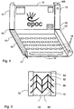
- Figure 5 shows an example of a frame provided to support the keyboard.
- the frame comprises three sets of folding support bars 52. Each set has four support bars which pivot about pivots 56 at both ends.
- the support bars 52 of each set are maintained in a parallel configuration with corresponding support bars 52 in the other sets.
- the support bars 52 mechanically connect the battery housing element 12 with the lower storage element 10.
- the mechanism further comprises three intermediate bars 58, which connect the three sets together.
- the intermediate bars 58 force corresponding support bars 52 from each set to stay parallel when the mobile station is extended or retracted.
- the support bars 52 comprise conductive material
- they can be used electrically to couple the keyboard and battery housing elements 10 and 12. Altematively, one of these sets can support an electrical lead coupling these elements.
- a similar frame arrangement can be used to support the display 15.
- Figure 6 shows a front view of the mobile station in a partially extended mode.
- the battery housing element 12 and the electronics housing element 13 are provided with a stop mechanism.
- the stop mechanism uses a stud 62 provided on the upper storing element 11.
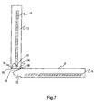
- Figure 7 shows a cross section of the view of the mobile station in Figure 6 along the line A-A'.
- This embodiment has three fixed opening angles.
- the electronics housing element 13 On a wall facing towards the upper storage element 11, the electronics housing element 13 has a recess 74 on its side at its lower end, close to the hinge 18..
- the recess has a form of a sector of approximately 45 degrees.
- the hinged end of the electronics housing element forms the first straight side or radius of the sector.
- the battery housing element 12 has a wall that faces towards the lower storage element 10. This wall has an extending flange 72.
- the flange is basically an extension of the wall going beyond the end of the battery housing element 12.
- the flange has a sector shape in side view.
- the flange has an arc extending from the lower side of the battery housing element. The arc extends over an angle of about 60 degrees and terminates at a straight side connecting the arc to the upper side of the battery housing element. The narrow apex of the flange is thus towards the hinge.
- the flange is aligned in proportion to the hinge so that it enters the recess when the mobile station is opened about the hinges. At a certain first opening angle, the flange fills the entire recess and a leading edge 73 meets the end 77 of the recess.
- the stop is an extension of the wall of the electronics housing element 13, which faces towards the upper storage element.
- the stop follows the plane of this wall and extends a few millimetres over the recess 74.
- the stop and the flange are both aligned to the level of the outer surfaces of the electronics housing element 13 and battery housing element 12.
- the stop 76 and the flange 72 occupy a common plane.
- the flange has two configurations, a relaxed and a bent configuration. In the bent configuration, the flange is slightly bent sideways.
- the recess is dimensioned deeply enough so that there is space behind the stop for the flange to slide, when the flange is in the bent configuration.
- the flange 72 has the first abutment surface 73 that is its leading edge. This surface prevents further opening of the mobile station beyond a certain opening angle.
- the recess 74 has an inner wall (the second direct wall of the sector) defining the second abutment surface 77, which defines the first opening angle. This first opening angle defines the maximum opening angle when the mobile station is being used as a telephone.
- the stop 76 provides a third abutment surface which faces roughly towards the hinged end of the electronics housing element.
- the stud 62 When the mobile station is being used as a data terminal that is in the extracted configuration, the stud 62 is far from the flange, the flange moves along the plane of the side walls of the battery and electronics housing elements, and at a certain point engages with the stop.
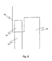
- the operation of the stop mechanism will now be described referring to Figures 6, 7 and 8.
- the flange 72 has a relaxed configuration in which it is not pressed upon by the stud 62. This is shown in Figure 6. In this configuration, when the flange engages the stop 76, further opening movement is prevented, and thus the maximum opening angle for the data terminal mode is defined. Additionally, the flange has a compressed configuration, in which the stud 62 presses the flange 72 into the recess. This happens when the mobile station is set into the telephone mode, that is the upper storage element 11 is brought next to the electronics housing element 13. In this compressed configuration, the first abutment surface 73 of the flange 72 can avoid the stop 76, and the flange slides through the gap.
- the mobile station can open until the flange is fully received by the recess 74, that is until the first abutment surface 73 engages the third abutment surface 77 of the recess.
- the battery housing element 12 and the electronics housing element 13 are stopped from opening any further.
- a mobile station according to the invention occupies in its transportation mode a fraction of its fully opened size.
- it also has an intermediate configuration provided to enable the mobile station to be used for telephony.
- the invention can be applied to mobile telephones, personal digital assistants and small laptop computers to provide a screen of a presentation size.
- it can be used for interactive posters in exhibitions, electronic games, user interfaces of various types of home and business electronics like hi-fi-sets, car audio systems, and multimedia devices used, for example, in aeroplanes.
Abstract
Description
- The invention relates to user interfaces, and relates especially to minimising the size of user interfaces.
- During the last two decades different types of small electronic input devices have been developed, especially for mobile telecommunication. These devices generally have a keypad comprising either a set of buttons typically used on a telephone handset or a small keyboard in the QWERTY format.
- It is common in such electronic input devices to provide a display to let a user see information which has been entered via the keypad or keyboard and to provide the user with other information such as received messages, instructions or other information. Developments in electronic and battery technologies have allowed manufacture of ever smaller devices having ever greater functionality. This improvement in functionality has enabled users to interact with electronic input devices in more ways, which has led to more menu options being available. Consequently, electronic input devices generally require a relatively large display and a large number of input keys. It is now common for users to carry their electronic input devices with them most of the time. This increased mobility generally limits the size of electronic input devices to a handheld size. Furthermore, since they are now often carried about, they need to be robust. There is thus a conflict between the need to have a large display and a large keyboard to allow ease of use and the need to have a small portable electronic input device.
- In order to keep the size of electronic input devices small, it is known to provide browsing menus to display only a small number of available options and/or information at any one time and to reduce the size of keyboard keys. However, user interfaces of newer and more complicated devices, such as mobile telephones and Personal Digital Assistants, often have a computer-like functionality, and so require a display which is capable of displaying text (having a number of rows) and graphics. QWERTY format keyboards are often provided. An example of such a device is the Nokia® 9000 Communicator. This is in the form of a two-part mobile station comprising a complete QWERTY format keyboard in one part and a display having 640 x 200 pixels in the other part. The two parts are joined together by a hinge.
- Document JP 06-164440 discloses a portable information communication equipment with a radio communication state and an electronic notebook state. The electronic device comprises three sections that are hinged together so that a first and a second part are hinged on a short horizontal side of the device, which when opened brings the device into the radio communication state revealing microphone, speaker, keypad and display. Further the second and third sections are hinged on a long vertical side of the device, and when opened brings the device into the electronic notebook state revealing display and keypad. At a time only the first or the third section is opened so that the device is either in the radio communication state or in the electronic notebook state.
- Document EP 860 969 (and corresponding US 6,311,076) discloses a mobile communication device that has a housing containing battery and electronic component compartments. Located along a central axis of the housing is a spring mounted roller to which is attached a flexible liquid crystal display. The housing contains a compartment between the roller and the outer wall of the housing for storing the display in a retracted position. An elongate slot extends axially along the housing such that the display can be pulled through the slot by a user to a withdrawn position in which the display is visible to the user. The display may be provided with one or more touch sensitive elements or 'buttons' which are accessible to the user when the display is withdrawn.
- Now a user interface for an electronic input device has been invented, which input device has an input means extractable from a storage space of the device into an extended state and retractable back into the storage space into a retracted state. Thus, the size of the data input device can conveniently be made smaller for transport whilst the input means is protected in the storage space. The electronic input device can subsequently be put into a larger size when the input means is to be used.
- According to a first aspect of the invention there is provided an electronic input device comprising:
- a flexible input means for receiving user input; and
- a housing defining a space for accommodating said input means;
- said input device has a first state, a second state and a third state; wherein
- the input device adopts a compact spatial configuration in the first state, a partly extended spatial configuration in the second state, and a fully extended spatial configuration in the third state, characterised in that
-
- in the second state the input means adopts a compacted spatial configuration and at least part of the functionality of the electronic input device is available for a user, and in the third state input means adopts an extended spatial configuration and the available functionality is extended.
- Preferably, the input means has an input surface having touch sensitive areas.
- Preferably, the compacted state is non-planar. All or part of the input means may adopt the compacted spatial configuration. In this way, a smaller input area, or no input area at all, is provided to the user.
- Preferably, the extended spatial configuration is planar. All or part of the input means may adopt the extended spatial configuration. In this way, the input means provides an input area to a user.
- Advantageously, the size of the electronic input device can be reduced, for example by gathering the input means either partially or entirely into the housing, and increased to reveal a convenient large input means, for example by letting out the input means either partially or entirely from the housing.
- Preferably, in the second configuration the input means is wound into a roll. Alternatively, it may be folded. In one embodiment, it is a concertina arrangement.
- Preferably, said device comprises means for moving said input means between said first and second configurations.
- Preferably, said input means is a keyboard. In an embodiment in which the input means is a keyboard its size can be changed considerably thus allowing construction of a small device with full keyboard functionality. It is an advantage of a full keyboard that the user can quickly and easily type text, and yet the input device can be compacted to a convenient small size to be easy to carry with the user during transportation.
- Preferably, said input means is a display. Preferably, part of the display is arranged to display a key to implement a soft key the function of which can be varied by software. This has an advantage of combining an input and output means so that the same surface can be used both for displaying information to the user and for reading user input, and thus it is not necessary to provide a separate display at all.
- Preferably, the electronic input device according to a second aspect of the invention comprises:
- a flexible output means for outputting information; and
- a housing defining a space for accommodating said output means; said input device has a first state, a second state and a third state; wherein
- the input device adopts a compact spatial configuration in the first state, a partly extended spatial configuration in the second state, and a fully extended spatial configuration in the third state, characterised in that
-
- Preferably, said flexible output means is a display.
- Advantageously, the size of the display can be changed to a high extent. This allows construction of a small device with a large enough display to show a large amount of information at any one time, for example a WWW (World Wide Web) page or e-mail.
- Preferably said output means and said input means are arranged so that the input device has two states corresponding to the first and second states of both input means and output means. In the first state both the input means and the output means are compacted and in the second state both the input means and the output means are extended. This provides the advantage of either simultaneous extension or simultaneous compaction of both the input means and the output means.
- Preferably, the electronic input device comprises a hinge for foldingly connecting the housing defining the space for accommodating said flexible output means to the housing defining a space for accommodating said input means. This provides an electronic input device, which has a relatively large display, and a relatively large input means and yet can be packed into a compact configuration. This is particularly useful in reducing the size of an electronic input device that is always carried by a user.
- Preferably, the electronic input device is a telecommunications device. The telecommunications device may have a data terminal mode in its extended spatial configuration and a telephone mode in its compacted spatial configuration.
- Preferably, the electronic input device comprises:
- two elements, which are foldable about a hinge between an open configuration and a closed configuration,
- a speaker located in one element, and
- a microphone in another element.
-
- The telecommunications device is unfoldable to separate the microphone and the speaker. In this way the speaker may be located conveniently close to a user's mouth and the microphone may be located conveniently close to the user's ear. Advantageously the elements can be folded together to reduce thei size of the electronic input device.
- Preferably, the electronic input device further comprises:
- a stop to prevent the device being opened beyond a certain maximum opening angle, and
- a means for changing the maximum opening angle when the configuration of the device is changed between the compacted spatial configuration and the extended spatial configuration. This provides different maximum opening angles for when the device is to be used in a telephone mode and when it is to be used in a data terminal mode. For example, it is possible to reduce the opening of the device to a convenient viewing angle for the data terminal mode. In the telephone mode, the mobile station can be further opened to increase the distance of the microphone and the speaker from each other.
-
- According to a third aspect of the invention there is a method of operating an electronic input device having a user interface, comprising the steps of:
- storing a flexible input means in a compacted spatial configuration within a housing of the electronic input device;
- moving the input device from a first state into a second state by moving a first portion of the device in relation to a second portion of the device in a first direction, wherein the input device adopts a compact spatial configuration in the first state and a partly extended spatial configuration in the second state;
- moving the input device from the second state into a third state by sliding a third portion of the device in a second direction being different than the first direction, the sliding comprising extending the flexible input means out of the housing into an extended spatial configuration for receiving user input, wherein the input device adopts a fully extended spatial configuration in the third state;
- allowing a user to access at least part of the functionality of the electronic input device when in the second state; and
- extending the available functionality of the electronic input device when in the third state; and
- allowing the input device to be moved from the third state into the second state by retrieving the flexible input means again into the compacted spatial configuration within the housing.
-
- The invention will now be described, by way of example only, with reference to the accompanying drawings, in which:
- Figure 1
- shows a perspective view from the front of a mobile station in a transport mode;
- Figure 2
- shows a side view of the mobile station of Figure 1 in a telephone mode;
- Figure 3
- shows a perspective view from the front of the mobile station of Figure 1 in a telephone mode;
- Figure 4
- shows a perspective view from the front of the mobile station of Figure 1 in a data terminal mode;
- Figure 5
- shows an example of a support mechanism;
- Figure 6
- shows a front view of the mobile station of Figure 1 in a partially extended mode;
- Figure 7
- shows a cross section of the mobile station of Figure 6 along line A-A'; and
- Figure 8
- shows enlarged detail of Figure 6.
- Figure 1 shows a mobile station MS in a retracted configuration, which is suitable for transportation and to be carried by a user, for example in a pocket. It can be seen that in this retracted, or folded-up, configuration the mobile station is basically of a cylindrical shape. The mobile station comprises four
elements lower storage element 10, anupper storage element 11, abattery element 12 and anelectronics housing element 13. Thebattery element 12 contains a battery for operating the mobile station. Theelectronics housing element 13 contains mobile station electronics to enable the mobile station to be used as, among other things, a mobile telephone and as a data terminal. - Referring now to Figures 2 and 3 it can be seen that
elements elements elements elements - Figure 3 shows a perspective view from the front of the mobile station of Figure 1 in an opened, that is telephone, configuration. The first and second entities have been moved relatively with respect to each other about the
hinges 18 and are disposed at an angle of about 115°. This is a comfortable angle for the mobile station to be used as a telephone or as a data terminal as will be described below. The opened configuration reveals atelephone speaker 20 located close to the upper end of theelectronics housing element 13 and amicrophone 21 located close to the lower end of thebattery element 12. Atelephone keypad 22 can be seen on a surface of thebattery element 12, which surface faces a corresponding surface of thelower storage element 10. In another embodiment of the invention, the user may give verbal input rather than pressing keys with the input being recognised by speech recognition. - Of course, the angle does not have to be exactly 115° but may be arbitrarily chosen. The angle may be either freely adjustable or it may be adjustable in certain steps. There may only be two possible angles at which the mobile station may be fixed: in a completely closed configuration, where the angle is 0°, and in an open configuration, where the angle is typically within a range of 90 to 270 degrees, preferably less than 180 degrees. Alternatively, there may be a third fixed angle so that there are different angles for telephone use and for data terminal use, as described later in this document.
- Figure 4 shows a perspective of the mobile station of Figure 1 in an extended, data terminal, configuration. Pairs of elements forming each of the first and second hinged entities, that is
elements elements flexible keyboard 14 and aflexible display 15 respectively. Theupper storage element 11 provides a storage space into which thekeyboard 14 can be wound and thelower storage element 10 provides a storing space into which thedisplay 15 can be wound. Both thekeyboard 14 and thedisplay 15 are arranged to be wound into their respective storage spaces so that the mobile station is in a suitable configuration for transportation or to be used as a telephone. This can be arranged by using any suitable means such as a springloaded or an electrically driven roller. In case of electrically driven winding, the battery can be connected to a miniature sized electrical motor in thelower storage element 10 with flexible wires extending beneath thekeyboard 14. Theelements respective pairs keyboard 14 and thedisplay 15 become removed from their storage spaces and unwound partially or to their full extents. Thekeyboard 14 and thedisplay 15 are electrically coupled to the electronics within theelectronics housing element 13. The device also comprises a flexible flat cable (not shown) extending across thehinges 18 to couple the battery, the keypad and thekeyboard 14 to the electronics in theelectronics housing element 13. Thus the electronics drives thedisplay 15 and receives input from thekeyboard 14. - Since the
keyboard 14 and thedisplay 15 are flexible and can be wound, they do not need to be sharply folded. Alternatively, thekeyboard 14 and thedisplay 15 may be stored in their respective storage spaces in a concertina type arrangement having a suitable mechanism to retract them. - In the extracted configuration, the
keyboard 14 and thedisplay 15 are parallel in the direction of their longest side, although they do not necessarily share the same plane. - In one embodiment of the invention the
keyboard 14 is a touch pad arrangement for sensing touch by a finger or by atouch pen 17 which is provided for this purpose. In this embodiment, thepen 17 is located in an end of thelower storage element 10. It is convenient to locate thepen 17 on, or adjacent to, an axis about which thekeyboard 14, is wound. In this way, thepen 17 may be located inside thekeyboard 14 when it is wound. Thekeyboard 14 is made of an EMFi film, as is known to a person skilled in the art. A set ofkeys 16 is printed on thekeyboard 14 to indicate to a user where to press. In another embodiment, the keys of the keyboard are not printed but instead the keyboard is capable of displayingvirtual keys 16, that is soft keys, which are to be pressed. Using soft keys allows dynamic mapping and thus enhances the variability of the keyboard so that it can be adapted to receive input of different kinds in different circumstances. For example, the mobile station can show legends for shortcut keys (such as CTRL A) adjacent to certain keys. These legends may be customised by different applications. In another embodiment, rather than providing a keyboard, a touch pad is provided which can be used as a drawing surface for a drawing application or used as a general input device. For example, it could be used to extend the display area to provide an expanded view to a document or an image. - The
display 15 is a paper-like display element. Manufacturers for such display elements comprise E-Ink Inc. & Massachusetts Institute of Technology and Rank Xerox Corporation. Rank Xerox has described one type of paper-like displays called "gyricon": "A gyricon sheet is a thin layer of transparent plastic in which millions of small beads, somewhat like toner particles, are randomly dispersed. The beads, each contained in an oil-filled cavity, are free to rotate within those cavities. The beads are 'bichromal', with hemispheres of contrasting color (e.g. black and white), and charged so they exhibit an electrical dipole. Under the influence of a voltage applied to the surface of the sheet, the beads rotate to present one colored side or the other to the viewer. A pattern of voltages can be applied to the surface in a bit-wise fashion to create images such as text and pictures. The image will persist until new voltage patterns are applied to create new images.' ...' For applications requiring more rapid and direct electronic update, the gyricon material might be packaged with a simple electrode structure on the surface and used more like a traditional display. Gyricon is described at http://www.parc.xerox.com/dhl/projects/epaper/. - The first hinged entity is relatively massive compared to the second hinged entity so that the first entity can lie flat upon a surface when the mobile station is opened. This applies even when the second hinged entity is disposed at an angle to the first hinged entity of more than 90°. In this way, the mobile station is self-supporting when in a data terminal mode. Therefore, the mobile station can be placed on a desk and not topple over. This stability can be provided by locating heavy parts of the mobile station, such as the battery, in the
battery housing element 12. Alternatively, it can be provided by locating the majority of the weight in thebattery housing element 12 away from thehinges 18 and the majority of the weight in theelectronics housing element 13 close to thehinges 18. - The mobile station may also comprise a frame located beneath the
keyboard 14 and thedisplay 15. The frame holds the mobile station in the extended configuration. The frame is extendable and retractable. The frame also provides support to the back faces of thekeyboard 14 and thedisplay 15 to enable the mobile station to be used on an uneven surface or in the hands of a user. In any case, whether or not a frame is provided, winding of thekeyboard 14 and thedisplay 15 can be arranged to occur only in response to user initiation so that the mobile station can be laid on a desk or other such flat surface and stay in the extended configuration. - Figure 5 shows an example of a frame provided to support the keyboard. The frame comprises three sets of folding support bars 52. Each set has four support bars which pivot about
pivots 56 at both ends. The support bars 52 of each set are maintained in a parallel configuration with corresponding support bars 52 in the other sets. The support bars 52 mechanically connect thebattery housing element 12 with thelower storage element 10. The mechanism further comprises threeintermediate bars 58, which connect the three sets together. Theintermediate bars 58 force corresponding support bars 52 from each set to stay parallel when the mobile station is extended or retracted. In an embodiment in which the support bars 52 comprise conductive material, they can be used electrically to couple the keyboard andbattery housing elements display 15. - Figure 6 shows a front view of the mobile station in a partially extended mode. The
battery housing element 12 and theelectronics housing element 13 are provided with a stop mechanism. The stop mechanism uses astud 62 provided on theupper storing element 11. - Figure 7 shows a cross section of the view of the mobile station in Figure 6 along the line A-A'. This embodiment has three fixed opening angles. On a wall facing towards the
upper storage element 11, theelectronics housing element 13 has arecess 74 on its side at its lower end, close to thehinge 18.. The recess has a form of a sector of approximately 45 degrees. The hinged end of the electronics housing element forms the first straight side or radius of the sector. - The
battery housing element 12 has a wall that faces towards thelower storage element 10. This wall has an extendingflange 72. The flange is basically an extension of the wall going beyond the end of thebattery housing element 12. The flange has a sector shape in side view. The flange has an arc extending from the lower side of the battery housing element. The arc extends over an angle of about 60 degrees and terminates at a straight side connecting the arc to the upper side of the battery housing element. The narrow apex of the flange is thus towards the hinge. The flange is aligned in proportion to the hinge so that it enters the recess when the mobile station is opened about the hinges. At a certain first opening angle, the flange fills the entire recess and aleading edge 73 meets theend 77 of the recess. - In order to provide two different opening angles, there is a
stop 76. The stop is an extension of the wall of theelectronics housing element 13, which faces towards the upper storage element. The stop follows the plane of this wall and extends a few millimetres over therecess 74. The stop and the flange are both aligned to the level of the outer surfaces of theelectronics housing element 13 andbattery housing element 12. In other words, thestop 76 and theflange 72 occupy a common plane. The flange has two configurations, a relaxed and a bent configuration. In the bent configuration, the flange is slightly bent sideways. The recess is dimensioned deeply enough so that there is space behind the stop for the flange to slide, when the flange is in the bent configuration. - There are three abutment surfaces. The
flange 72 has thefirst abutment surface 73 that is its leading edge. This surface prevents further opening of the mobile station beyond a certain opening angle. Therecess 74 has an inner wall (the second direct wall of the sector) defining thesecond abutment surface 77, which defines the first opening angle. This first opening angle defines the maximum opening angle when the mobile station is being used as a telephone. Thestop 76 provides a third abutment surface which faces roughly towards the hinged end of the electronics housing element. When the mobile station is being used as a data terminal that is in the extracted configuration, thestud 62 is far from the flange, the flange moves along the plane of the side walls of the battery and electronics housing elements, and at a certain point engages with the stop. - The operation of the stop mechanism will now be described referring to Figures 6, 7 and 8. The
flange 72 has a relaxed configuration in which it is not pressed upon by thestud 62. This is shown in Figure 6. In this configuration, when the flange engages thestop 76, further opening movement is prevented, and thus the maximum opening angle for the data terminal mode is defined. Additionally, the flange has a compressed configuration, in which thestud 62 presses theflange 72 into the recess. This happens when the mobile station is set into the telephone mode, that is theupper storage element 11 is brought next to theelectronics housing element 13. In this compressed configuration, thefirst abutment surface 73 of theflange 72 can avoid thestop 76, and the flange slides through the gap. Thus, the mobile station can open until the flange is fully received by therecess 74, that is until thefirst abutment surface 73 engages thethird abutment surface 77 of the recess. When the abutment surfaces are in contact, thebattery housing element 12 and theelectronics housing element 13 are stopped from opening any further. - The present invention provides several advantages over the prior art. A mobile station according to the invention occupies in its transportation mode a fraction of its fully opened size. In addition, it also has an intermediate configuration provided to enable the mobile station to be used for telephony. The invention can be applied to mobile telephones, personal digital assistants and small laptop computers to provide a screen of a presentation size. Alternatively it can be used for interactive posters in exhibitions, electronic games, user interfaces of various types of home and business electronics like hi-fi-sets, car audio systems, and multimedia devices used, for example, in aeroplanes.
- This paper presents the implementation and embodiments of the invention with the help of examples. It is obvious to a person skilled in the art, that the invention is not restricted to details of the embodiments presented above, and that the invention can be implemented in another embodiment without deviating from the characteristics of the invention. The invention was here described using the most complex embodiment as an example, but naturally the invention can also be implemented in a device comprising merely a retracting keyboard without neither display properties nor mobile telephone functionality etc.
the input device is configured to be moved from the first state into the second state by movement of a first portion of the device in relation to a second portion of the device in a first direction, and the device is configured to be moved from the second state into the third state by a sliding movement of a third portion of the device in a second direction being different than the first direction, and
the input device is configured to be moved from the first state into the second state by movement of a first portion of the device in relation to a second portion of the device in a first direction, and the device is configured to be moved from the second state into the third state by a sliding movement of a third portion of the device in a second direction being different than the first direction, and
in the second state the output means adopts a compacted spatial configuration and at least part of the functionality of the electronic input device is available for a user, and in the third state output means adopts an extended spatial configuration and the available functionality is extended.
Claims (22)
- An electronic input device (MS) comprising:characterised in thata flexible input means (14) for receiving user input; anda housing (10) defining a space for accommodating said input means;said input device has a first state (Figure 1), a second state (Figure 3) and a third state (Figure 4); whereinthe input device adopts a compact spatial configuration in the first state, a partly extended spatial configuration in the second state, and a fully extended spatial configuration in the third state,
the input device is configured to be moved from the first state into the second state (Figure 3) by movement of a first portion of the device in relation to a second portion of the device in a first direction, and the device is configured to be moved from the second state into the third state (Figure 4) by a sliding movement of a third portion of the device in a second direction being different than the first direction, and
in the second state the input means adopts a compacted spatial configuration and at least part of the functionality of the electronic input device is available for a user, and in the third state input means adopts an extended spatial configuration and the available functionality is extended. - An electronic input device (MS) according to claim 1, wherein the input means (14) has an input surface having touch sensitive areas (16).
- An electronic input device (MS) according to claim 1 or 2, wherein the extended spatial configuration is planar.
- An electronic input device (MS) according to any preceding claim, wherein the compacted spatial configuration is non-planar.
- An electronic input device (MS) according to any preceding claim, wherein in the compacted spatial configuration the input means (14) is wound into a roll.
- An electronic input device (MS) according to any preceding claim, comprising means (11, 12) for moving said input means (14) between said first and second configurations.
- An electronic input device (MS) according to any of preceding claims, wherein said input means is a keyboard (14).
- An electronic input device (MS) according to any of preceding claims, wherein said input means (14) is also a display.
- An electronic input device (MS) according to claim 1, wherein the device is configured to pull the third portion in the second direction.
- An electronic input device (MS) according to claim 9, wherein the device comprises a first (10) and a second (12) element which are configured to be grasped by the user in order to pull the first and the second element away from each other.
- An electronic input device (MS) according to claim 10, wherein the first element (10) comprises a storing space in which a flexible input means is stored when the device is in the second state, and from which the flexible input means (14) is extracted when the device is moved into the third state.
- An electronic input device (MS) comprising:characterised in thata flexible output means (15) for outputting information; anda housing (11) defining a space for accommodating said output means; said input device has a first state (Figure 1), a second state (Figure 3) and a third state (Figure 4); whereinthe input device adopts a compact spatial configuration in the first state, a partly extended spatial configuration in the second state, and a fully extended spatial configuration in the third state,
the input device is configured to be moved from the first state into the second state (Figure 3) by movement of a first portion of the device in relation to a second portion of the device in a first direction, and the device is configured to be moved from the second state into the third state (Figure 4) by a sliding movement of a third portion of the device in a second direction being different than the first direction, and
in the second state the output means adopts a compacted spatial configuration and at least part of the functionality of the electronic input device is available for a user, and in the third state output means adopts an extended spatial configuration and the available functionality is extended. - An electronic input device (MS) according to claim 12, wherein said output means is a display (15).
- An electronic input device (MS) according to claim 12 or 13, wherein said output means is arranged parallel with said input means so that the input device has two states corresponding to the first and second states of both input means and output means.
- An electronic input device (MS) according to any of claims 12 to 14, comprising a hinge (18) for foldingly connecting the housing (11) defining the space for accommodating said output means to the housing (10) defining a space for accommodating input means.
- An electronic input device (MS) according to any preceding claim, wherein the electronic input device is a telecommunications device.
- An electronic input device (MS) according to claim 16 comprising:two elements (10 and 12,11 and 13), which are foldable about a hinge (18) between an open configuration and a closed configuration;a speaker (20) located in one element, anda microphone (21) in another element so that the electronic input device can be unfolded to separate the microphone and the speaker.
- An electronic input device (MS) according to claim 17 comprising:a stop (76) to resist opening the two elements (10 and 12,11 and 13) of the input device over a certain maximum opening angle, andmeans for changing the maximum opening angle when the configuration of the device is changed between the compacted spatial configuration and the extended spatial configuration.
- An electronic input device (MS) according to claim 1, wherein the device is configured to pull the third portion in the second direction.
- An electronic input device (MS) according to claim 9, wherein the device comprises a first (10) and a second (12) element which are configured to be grasped by the user in order to pull the first and the second element away from each other.
- An electronic input device (MS) according to claim 10, wherein the first element (10) comprises a storing space in which a flexible output means is stored when the device is in the second state, and from which the flexible output means (14) is extracted when the device is moved into the third state.
- A method of operating an electronic input device having a user interface, comprising the steps of:storing a flexible input means in a compacted spatial configuration within a housing of the electronic input device;moving the input device from a first state into a second state by moving a first portion of the device in relation to a second portion of the device in a first direction, wherein the input device adopts a compact spatial configuration in the first state and a partly extended spatial configuration in the second state;moving the input device from the second state into a third state by sliding a third portion of the device in a second direction being different than the first direction, the sliding comprising extending the flexible input means out of the housing into an extended spatial configuration for receiving user input, wherein the input device adopts a fully extended spatial configuration in the third state;allowing a user to access at least part of the functionality of the electronic input device when in the second state; andextending the available functionality of the electronic input device when in the third state; andallowing the input device to be moved from the third state into the second state by retrieving the flexible input means again into the compacted spatial configuration within the housing.
Applications Claiming Priority (3)
| Application Number | Priority Date | Filing Date | Title |
|---|---|---|---|
| FI992636A FI111998B (en) | 1999-12-08 | 1999-12-08 | User interface |
| FI992636 | 1999-12-08 | ||
| PCT/FI2000/000995 WO2001042891A1 (en) | 1999-12-08 | 2000-11-14 | User interface |
Publications (2)
| Publication Number | Publication Date |
|---|---|
| EP1238325A1 EP1238325A1 (en) | 2002-09-11 |
| EP1238325B1 true EP1238325B1 (en) | 2003-06-18 |
Family
ID=8555716
Family Applications (1)
| Application Number | Title | Priority Date | Filing Date |
|---|---|---|---|
| EP00977624A Expired - Lifetime EP1238325B1 (en) | 1999-12-08 | 2000-11-14 | User interface |
Country Status (8)
| Country | Link |
|---|---|
| US (2) | US6873315B2 (en) |
| EP (1) | EP1238325B1 (en) |
| CN (1) | CN1322389C (en) |
| AT (1) | ATE243332T1 (en) |
| AU (1) | AU1527201A (en) |
| DE (1) | DE60003463T2 (en) |
| FI (1) | FI111998B (en) |
| WO (1) | WO2001042891A1 (en) |
Cited By (2)
| Publication number | Priority date | Publication date | Assignee | Title |
|---|---|---|---|---|
| USRE43931E1 (en) | 1997-12-30 | 2013-01-15 | Ericsson Inc. | Radiotelephones having contact-sensitive user interfaces and methods of operating same |
| DE102012101210A1 (en) | 2012-02-15 | 2013-08-22 | Maxim Stührenberg | Display device e.g. contact-sensitive display device, for use in mobile telephone for displaying images, has holding unit holding displaying unit in utilized condition and temporary extendably arranged on housing in discharging direction |
Families Citing this family (65)
| Publication number | Priority date | Publication date | Assignee | Title |
|---|---|---|---|---|
| EP1259381A1 (en) | 2000-02-01 | 2002-11-27 | R.A.S.T. Associates | Expandable and contractible keyboard with adjustable key sizes |
| US6739774B1 (en) * | 2000-02-01 | 2004-05-25 | Rast Associates, Llc | Expandable and contractible keyboard with adjustable key sizes |
| GB2370657A (en) * | 2000-12-28 | 2002-07-03 | Constantinos Hadjisotiriou | Foldable flexible computer |
| EP1251673A1 (en) * | 2001-04-20 | 2002-10-23 | E-Trade Int'l Group Limited | Consumerelectronics device and actuation arrangement therefor |
| US6554619B2 (en) * | 2001-04-25 | 2003-04-29 | Jacquelyn Williams | Electronic instructional device for point-of-performance instruction |
| US20030048256A1 (en) * | 2001-09-07 | 2003-03-13 | Salmon Peter C. | Computing device with roll up components |
| DE20118593U1 (en) * | 2001-11-16 | 2002-05-23 | Jahn Hartmut | Multifunctional communication device |
| US6882336B2 (en) | 2001-12-06 | 2005-04-19 | Rast Associates, Llc | Expandable and contractible keyboard device |
| AU2002360518A1 (en) * | 2001-12-12 | 2003-06-23 | Universal Display Corporation | Intelligent multi-media display communication system |
| US7050835B2 (en) | 2001-12-12 | 2006-05-23 | Universal Display Corporation | Intelligent multi-media display communication system |
| US7382355B2 (en) * | 2003-03-25 | 2008-06-03 | Sony Ericsson Mobile Communications Ab | Extractable terminal keypad |
| DE60310874T2 (en) * | 2003-03-25 | 2007-09-06 | Sony Ericsson Mobile Communications Ab | Extractable terminal keypad |
| WO2004088490A2 (en) * | 2003-04-01 | 2004-10-14 | Koninklijke Philips Electronics N.V. | Apparatus with display |
| EP1480417B1 (en) * | 2003-05-21 | 2006-07-19 | Sony Ericsson Mobile Communications AB | Clamshell-type mobile terminal with flexible display |
| EP1642253B1 (en) * | 2003-06-23 | 2012-10-03 | Simon Richard Daniel | Display device having an extendible screen |
| US7173781B2 (en) * | 2003-06-26 | 2007-02-06 | Seagate Technology Llc | Multi-tracks MR offset tuning based on error count in certification process |
| FI20040853A (en) | 2004-06-18 | 2005-12-19 | Nokia Corp | Opening and closing a user interface element |
| US7667962B2 (en) | 2004-08-20 | 2010-02-23 | Mullen Jeffrey D | Wireless devices with flexible monitors and keyboards |
| US20060068722A1 (en) * | 2004-09-28 | 2006-03-30 | Ashman William C Jr | Wireless communications device with extendable and retractable input/output device |
| WO2006038171A1 (en) * | 2004-10-05 | 2006-04-13 | Koninklijke Philips Electronics, N.V. | Rollable display device |
| TWI259715B (en) * | 2005-01-25 | 2006-08-01 | Wistron Corp | Electronic device able to adjust the size of the display area |
| JP4386940B2 (en) * | 2005-03-18 | 2009-12-16 | 富士通株式会社 | Remote control device |
| EP1882217A2 (en) * | 2005-05-20 | 2008-01-30 | Polymer Vision Limited | Protective cover for flexible display screen |
| KR101278604B1 (en) | 2005-05-23 | 2013-06-25 | 크리에이터 테크놀로지 비.브이. | Partially Flexible Displays Device |
| US7558057B1 (en) | 2005-06-06 | 2009-07-07 | Alex Naksen | Personal digital device with adjustable interface |
| TW200717420A (en) * | 2005-06-29 | 2007-05-01 | Koninkl Philips Electronics Nv | Foldable devices having flexible display screens |
| US8406866B2 (en) * | 2005-12-06 | 2013-03-26 | St. Jude Medical, Atrial Fibrillation Division, Inc. | System and method for assessing coupling between an electrode and tissue |
| CN101443695B (en) * | 2005-12-16 | 2011-12-28 | 创造者科技有限公司 | Circular displays |
| WO2007072234A1 (en) * | 2005-12-20 | 2007-06-28 | Polymer Vision Limited | Display device having an extendable flexible screen rollable around a batter |
| US7532460B2 (en) * | 2005-12-29 | 2009-05-12 | Sap Ag | Portable computer system |
| US8068605B2 (en) * | 2006-03-07 | 2011-11-29 | Sony Ericsson Mobile Communications Ab | Programmable keypad |
| JP5108293B2 (en) * | 2006-12-20 | 2012-12-26 | 富士フイルム株式会社 | Portable device and imaging device |
| TWI413037B (en) * | 2007-06-15 | 2013-10-21 | Creator Technology Bv | Electronic device with a variable angulation of a flexible display |
| CN101872254A (en) * | 2009-04-24 | 2010-10-27 | 鸿富锦精密工业(深圳)有限公司 | Portable handwriting input device |
| US8591128B2 (en) * | 2009-07-01 | 2013-11-26 | Nokia Corporation | Extendable mechanism |
| US8111505B2 (en) * | 2009-10-16 | 2012-02-07 | Apple Inc. | Computer housing |
| US8379377B2 (en) | 2010-01-20 | 2013-02-19 | Creator Technology B.V. | Electronic device with at least one extendable display section |
| KR101067587B1 (en) * | 2010-01-29 | 2011-09-27 | 주식회사 팬택 | Flexible terminal with shape conversion characteristics, shape conversion method and shape conversion device |
| KR101227644B1 (en) * | 2010-08-10 | 2013-01-30 | 유상규 | Rollable flexible display device |
| US20120086630A1 (en) * | 2010-10-12 | 2012-04-12 | Sony Computer Entertainment Inc. | Using a portable gaming device to record or modify a game or application in real-time running on a home gaming system |
| US9286812B2 (en) | 2011-06-07 | 2016-03-15 | Microsoft Technology Licensing, Llc | Flexible display extendable assembly |
| US20130002114A1 (en) * | 2011-06-29 | 2013-01-03 | Polymer Vision B.V. | Flexible Display With Cover Positioning Means |
| US8711566B2 (en) * | 2011-09-02 | 2014-04-29 | Microsoft Corporation | Expandable mobile device |
| KR102148717B1 (en) | 2011-12-05 | 2020-08-28 | 삼성전자주식회사 | Method for controlling display in a portable terminal and apparatus thereof |
| WO2013083945A2 (en) * | 2011-12-05 | 2013-06-13 | Massimiliano Scarano | Smartphone with oled that turns into tablet |
| JP5783039B2 (en) * | 2011-12-28 | 2015-09-24 | 富士通株式会社 | Multi-divided housing coupling device and electronic device including the coupling device |
| FI20120340A (en) * | 2012-10-08 | 2014-04-09 | Canatu Oy | Touch interface device and structure |
| CN105164602A (en) * | 2013-04-30 | 2015-12-16 | 富士通株式会社 | Coupling device for multi-part cases and electronic device comprising said coupling device |
| KR102072686B1 (en) * | 2013-06-05 | 2020-02-03 | 엘지전자 주식회사 | Image display device |
| KR102066716B1 (en) | 2013-06-20 | 2020-01-15 | 삼성전자주식회사 | Method of operating and electronic device thereof |
| CN104424844B (en) * | 2013-08-26 | 2017-04-19 | 联想(北京)有限公司 | Flexible display device and electronic product |
| CN104656774B (en) * | 2013-11-20 | 2020-02-21 | 联想(北京)有限公司 | Electronic equipment |
| WO2016045121A1 (en) * | 2014-09-28 | 2016-03-31 | Hewlett-Packard Development Company,L.P. | Electronic touch buttons |
| WO2016101123A1 (en) * | 2014-12-23 | 2016-06-30 | 深圳市柔宇科技有限公司 | Flexible screen extension structure, flexible screen assembly, and terminal |
| KR102277260B1 (en) * | 2014-12-29 | 2021-07-14 | 엘지전자 주식회사 | Terminal device and controlling method thereof |
| KR102301500B1 (en) * | 2015-01-22 | 2021-09-13 | 삼성디스플레이 주식회사 | Display device |
| US9625948B2 (en) * | 2015-08-24 | 2017-04-18 | Apple Inc. | Electronic devices with retractable displays |
| KR102492731B1 (en) * | 2016-06-09 | 2023-01-27 | 삼성디스플레이 주식회사 | Rollable display device |
| KR102534580B1 (en) * | 2016-07-27 | 2023-05-19 | 삼성디스플레이 주식회사 | Display device |
| US20190235579A1 (en) * | 2016-09-29 | 2019-08-01 | Shenzhen Royole Technologies Co., Ltd. | Electronic device |
| WO2018120086A1 (en) * | 2016-12-30 | 2018-07-05 | 深圳市柔宇科技有限公司 | Support assembly and display device |
| CN108874031B (en) * | 2018-05-23 | 2021-08-17 | 上海创功通讯技术有限公司 | Screen switching method and device and terminal |
| TWI675235B (en) | 2018-10-11 | 2019-10-21 | 友達光電股份有限公司 | Display apparatus |
| KR20200128319A (en) * | 2019-05-03 | 2020-11-12 | 삼성디스플레이 주식회사 | Display device |
| CN113472925B (en) * | 2021-06-29 | 2023-09-05 | Oppo广东移动通信有限公司 | Locking device and electronic equipment |
Family Cites Families (43)
| Publication number | Priority date | Publication date | Assignee | Title |
|---|---|---|---|---|
| US4145584A (en) * | 1976-04-28 | 1979-03-20 | Otterlei Jon L | Flexible keyboard switch with integral spacer protrusions |
| JPS63132323A (en) * | 1986-08-27 | 1988-06-04 | テキサス インスツルメンツ インコ−ポレイテツド | Data entry apparatus and interactive type communication |
| US4906843A (en) * | 1987-12-31 | 1990-03-06 | Marq Technolgies | Combination mouse, optical scanner and digitizer puck |
| JP2776658B2 (en) * | 1991-10-15 | 1998-07-16 | 日本電気株式会社 | keyboard |
| US5341154A (en) * | 1991-12-27 | 1994-08-23 | Bird Gregory F | Portable personal computer |
| US5220521A (en) | 1992-01-02 | 1993-06-15 | Cordata Incorporated | Flexible keyboard for computers |
| US5491651A (en) * | 1992-05-15 | 1996-02-13 | Key, Idea Development | Flexible wearable computer |
| US5278779A (en) * | 1992-06-26 | 1994-01-11 | Conway Kevin M | Laptop computer with hinged keyboard |
| JP3179217B2 (en) * | 1992-11-16 | 2001-06-25 | 株式会社日立製作所 | Portable information communication device |
| US5644338A (en) * | 1993-05-26 | 1997-07-01 | Bowen; James H. | Ergonomic laptop computer and ergonomic keyboard |
| US5616897A (en) * | 1993-06-30 | 1997-04-01 | Weber; Michael R. | Flexible keyboard |
| US5898161A (en) * | 1994-08-29 | 1999-04-27 | Symbol Technologies, Inc. | Wrist-mounted optical scanning and pointing systems |
| US5517683A (en) * | 1995-01-18 | 1996-05-14 | Cycomm Corporation | Conformant compact portable cellular phone case system and connector |
| KR100204158B1 (en) * | 1995-10-06 | 1999-06-15 | 윤종용 | Devidable keyboard |
| US5687058A (en) * | 1995-10-11 | 1997-11-11 | Mallinckrodt & Mallinckrodt | Method and apparatus for reducing at least one dimension of a computer keyboard for transportation and storage |
| FI111897B (en) * | 1995-11-24 | 2003-09-30 | Nokia Corp | Dual-acting communication device |
| WO1997022084A1 (en) * | 1995-12-11 | 1997-06-19 | Wolfgang Beyer | Chip card |
| US6046730A (en) * | 1996-03-15 | 2000-04-04 | At&T Corp | Backlighting scheme for a multimedia terminal keypad |
| US6073027A (en) * | 1996-08-29 | 2000-06-06 | Bellsouth Corporation | Portable radiotelephone with sliding cover and automatic antenna extension |
| GB9622349D0 (en) * | 1996-10-28 | 1997-01-08 | Therefore Limited | Hand held computer and communications apparatus |
| US6486862B1 (en) * | 1996-10-31 | 2002-11-26 | Kopin Corporation | Card reader display system |
| US5703578A (en) * | 1997-01-16 | 1997-12-30 | International Business Machines Corporation | Folding keyboard |
| FI103238B (en) | 1997-02-21 | 1999-05-14 | Nokia Mobile Phones Ltd | Mobile communication devices |
| US6067704A (en) * | 1997-06-12 | 2000-05-30 | Livernois Research And Development Company | Apparatus for assembling heat exchanger cores |
| US6075510A (en) * | 1997-10-28 | 2000-06-13 | Nortel Networks Corporation | Low power refreshing (smart display multiplexing) |
| US5995025A (en) * | 1997-12-18 | 1999-11-30 | Daniel I. Sternglass | Folding keyboard with sliding segments for electronic products |
| JPH11272205A (en) * | 1998-03-19 | 1999-10-08 | Toshiba Corp | Display device |
| US6307751B1 (en) * | 1998-06-01 | 2001-10-23 | Wearlogic, Inc. | Flexible circuit assembly |
| US6697043B1 (en) * | 1999-12-21 | 2004-02-24 | Immersion Corporation | Haptic interface device and actuator assembly providing linear haptic sensations |
| JP2000132122A (en) * | 1998-10-28 | 2000-05-12 | Fuji Photo Film Co Ltd | Scroll-type display capable of continuous display |
| AU2791800A (en) * | 1999-03-10 | 2000-09-28 | Robert O. Renfer | Mobile telephone with a roll-out keyboard |
| US6249672B1 (en) * | 1999-03-19 | 2001-06-19 | Mobile Communications Holdings, Inc. | Portable telephone |
| KR100742547B1 (en) * | 1999-05-06 | 2007-07-25 | 퀄컴 인코포레이티드 | Selecting flip phone operating mode using flip position |
| US6259409B1 (en) * | 1999-07-22 | 2001-07-10 | 3Com Corporation | Retractable sliding antenna assembly for wireless communication |
| US6774819B1 (en) * | 1999-07-23 | 2004-08-10 | Intel Corporation | Flexible keyboard |
| US6397078B1 (en) * | 1999-08-27 | 2002-05-28 | Young S. Kim | Combined mobile telephone and personal digital assistant |
| US6332084B1 (en) * | 1999-10-09 | 2001-12-18 | Qualcomm Incorporated | Multiple mode wireless telephone |
| US6774888B1 (en) * | 2000-06-19 | 2004-08-10 | International Business Machines Corporation | Personal digital assistant including a keyboard which also acts as a cover |
| US6594142B2 (en) * | 2000-07-19 | 2003-07-15 | Pocketop Computers Corp. | Folding keyboard for a personal digital assistant |
| WO2002008849A2 (en) * | 2000-07-24 | 2002-01-31 | Herman Ehrenburg | Computer-compatible, color-coded manual input system |
| US6894211B2 (en) * | 2001-09-21 | 2005-05-17 | Yamaha Corporation | Keyboard apparatus |
| JP3963693B2 (en) * | 2001-10-15 | 2007-08-22 | 富士通株式会社 | Conductive organic compound and electronic device |
| US20060066590A1 (en) * | 2004-09-29 | 2006-03-30 | Masanori Ozawa | Input device |
-
1999
- 1999-12-08 FI FI992636A patent/FI111998B/en not_active IP Right Cessation
-
2000
- 2000-11-14 CN CNB008169039A patent/CN1322389C/en not_active Expired - Fee Related
- 2000-11-14 AU AU15272/01A patent/AU1527201A/en not_active Abandoned
- 2000-11-14 EP EP00977624A patent/EP1238325B1/en not_active Expired - Lifetime
- 2000-11-14 DE DE60003463T patent/DE60003463T2/en not_active Expired - Lifetime
- 2000-11-14 WO PCT/FI2000/000995 patent/WO2001042891A1/en active IP Right Grant
- 2000-11-14 AT AT00977624T patent/ATE243332T1/en not_active IP Right Cessation
- 2000-12-05 US US09/730,066 patent/US6873315B2/en not_active Expired - Fee Related
-
2005
- 2005-02-10 US US11/055,774 patent/US7253802B2/en not_active Expired - Lifetime
Cited By (3)
| Publication number | Priority date | Publication date | Assignee | Title |
|---|---|---|---|---|
| USRE43931E1 (en) | 1997-12-30 | 2013-01-15 | Ericsson Inc. | Radiotelephones having contact-sensitive user interfaces and methods of operating same |
| US8812059B2 (en) | 1997-12-30 | 2014-08-19 | Ericsson, Inc. | Radiotelephones having contact-sensitive user interfaces and methods of operating same |
| DE102012101210A1 (en) | 2012-02-15 | 2013-08-22 | Maxim Stührenberg | Display device e.g. contact-sensitive display device, for use in mobile telephone for displaying images, has holding unit holding displaying unit in utilized condition and temporary extendably arranged on housing in discharging direction |
Also Published As
| Publication number | Publication date |
|---|---|
| FI19992636A (en) | 2001-06-09 |
| AU1527201A (en) | 2001-06-18 |
| FI111998B (en) | 2003-10-15 |
| US7253802B2 (en) | 2007-08-07 |
| DE60003463T2 (en) | 2004-05-06 |
| US20010003450A1 (en) | 2001-06-14 |
| US6873315B2 (en) | 2005-03-29 |
| ATE243332T1 (en) | 2003-07-15 |
| CN1322389C (en) | 2007-06-20 |
| US20050146498A1 (en) | 2005-07-07 |
| WO2001042891A1 (en) | 2001-06-14 |
| CN1678970A (en) | 2005-10-05 |
| DE60003463D1 (en) | 2003-07-24 |
| EP1238325A1 (en) | 2002-09-11 |
Similar Documents
| Publication | Publication Date | Title |
|---|---|---|
| EP1238325B1 (en) | User interface | |
| CN107077168B (en) | Mobile computing device with flexible hinge structure | |
| EP3462624B1 (en) | Clam-shell communications device with multiple screens and control thereof | |
| US8064962B2 (en) | Displays for portable electronic apparatus | |
| US7158634B2 (en) | Portable electronic devices | |
| US7622685B2 (en) | Portable information terminal | |
| US6798649B1 (en) | Mobile computer with foldable keyboard | |
| US20080129647A1 (en) | Multi-sided display for portable computer | |
| US20070211036A1 (en) | Roll-out touch screen support system (ROTS3) | |
| JPH1168896A (en) | Portable radio equipment | |
| CN111933028A (en) | Display device | |
| US8369071B2 (en) | Portable terminal | |
| JP2004118794A (en) | Input device equipped with rollable display and foldable keyboard and personal computer equipped with the input device | |
| KR20040025624A (en) | Dual slide display | |
| CN202103716U (en) | Hinge double screen-type cell-phone video display device | |
| JPH11212665A (en) | Thinned computer system | |
| JP2004118151A (en) | Input device provided with scrolling display and foldable keyboard, and personal computer provided with the same | |
| CN114241913A (en) | Bendable display module and display device | |
| JP3726052B2 (en) | Mobile terminal device | |
| CN115331555B (en) | display device | |
| KR20030091402A (en) | Display device of mobile phone | |
| JP5780575B2 (en) | Display device and information display device | |
| CN115052061A (en) | Electronic device | |
| JP2004118792A (en) | Input device equipped with rollable display and foldable keyboard and personal computer equipped with the input device |
Legal Events
| Date | Code | Title | Description |
|---|---|---|---|
| PUAI | Public reference made under article 153(3) epc to a published international application that has entered the european phase |
Free format text: ORIGINAL CODE: 0009012 |
|
| 17P | Request for examination filed |
Effective date: 20020708 |
|
| AK | Designated contracting states |
Kind code of ref document: A1 Designated state(s): AT BE CH CY DE DK ES FI FR GB LI |
|
| AX | Request for extension of the european patent |
Free format text: AL;LT;LV;MK;RO;SI |
|
| GRAH | Despatch of communication of intention to grant a patent |
Free format text: ORIGINAL CODE: EPIDOS IGRA |
|
| GRAH | Despatch of communication of intention to grant a patent |
Free format text: ORIGINAL CODE: EPIDOS IGRA |
|
| GRAA | (expected) grant |
Free format text: ORIGINAL CODE: 0009210 |
|
| AK | Designated contracting states |
Designated state(s): AT BE CH CY DE DK ES FI FR GB GR IE IT LI LU MC NL PT SE TR |
|
| PG25 | Lapsed in a contracting state [announced via postgrant information from national office to epo] |
Ref country code: IT Free format text: LAPSE BECAUSE OF FAILURE TO SUBMIT A TRANSLATION OF THE DESCRIPTION OR TO PAY THE FEE WITHIN THE PRE;WARNING: LAPSES OF ITALIAN PATENTS WITH EFFECTIVE DATE BEFORE 2007 MAY HAVE OCCURRED AT ANY TIME BEFORE 2007. THE CORRECT EFFECTIVE DATE MAY BE DIFFERENT FROM THE ONE RECORDED.SCRIBED TIME-LIMIT Effective date: 20030618 Ref country code: BE Free format text: LAPSE BECAUSE OF FAILURE TO SUBMIT A TRANSLATION OF THE DESCRIPTION OR TO PAY THE FEE WITHIN THE PRESCRIBED TIME-LIMIT Effective date: 20030618 Ref country code: CH Free format text: LAPSE BECAUSE OF FAILURE TO SUBMIT A TRANSLATION OF THE DESCRIPTION OR TO PAY THE FEE WITHIN THE PRESCRIBED TIME-LIMIT Effective date: 20030618 Ref country code: AT Free format text: LAPSE BECAUSE OF FAILURE TO SUBMIT A TRANSLATION OF THE DESCRIPTION OR TO PAY THE FEE WITHIN THE PRESCRIBED TIME-LIMIT Effective date: 20030618 Ref country code: LI Free format text: LAPSE BECAUSE OF FAILURE TO SUBMIT A TRANSLATION OF THE DESCRIPTION OR TO PAY THE FEE WITHIN THE PRESCRIBED TIME-LIMIT Effective date: 20030618 Ref country code: TR Free format text: LAPSE BECAUSE OF FAILURE TO SUBMIT A TRANSLATION OF THE DESCRIPTION OR TO PAY THE FEE WITHIN THE PRESCRIBED TIME-LIMIT Effective date: 20030618 Ref country code: FI Free format text: LAPSE BECAUSE OF FAILURE TO SUBMIT A TRANSLATION OF THE DESCRIPTION OR TO PAY THE FEE WITHIN THE PRESCRIBED TIME-LIMIT Effective date: 20030618 |
|
| REG | Reference to a national code |
Ref country code: GB Ref legal event code: FG4D |
|
| REG | Reference to a national code |
Ref country code: CH Ref legal event code: EP |
|
| REG | Reference to a national code |
Ref country code: IE Ref legal event code: FG4D |
|
| REF | Corresponds to: |
Ref document number: 60003463 Country of ref document: DE Date of ref document: 20030724 Kind code of ref document: P |
|
| PG25 | Lapsed in a contracting state [announced via postgrant information from national office to epo] |
Ref country code: SE Free format text: LAPSE BECAUSE OF FAILURE TO SUBMIT A TRANSLATION OF THE DESCRIPTION OR TO PAY THE FEE WITHIN THE PRESCRIBED TIME-LIMIT Effective date: 20030918 Ref country code: GR Free format text: LAPSE BECAUSE OF FAILURE TO SUBMIT A TRANSLATION OF THE DESCRIPTION OR TO PAY THE FEE WITHIN THE PRESCRIBED TIME-LIMIT Effective date: 20030918 Ref country code: PT Free format text: LAPSE BECAUSE OF FAILURE TO SUBMIT A TRANSLATION OF THE DESCRIPTION OR TO PAY THE FEE WITHIN THE PRESCRIBED TIME-LIMIT Effective date: 20030918 Ref country code: DK Free format text: LAPSE BECAUSE OF FAILURE TO SUBMIT A TRANSLATION OF THE DESCRIPTION OR TO PAY THE FEE WITHIN THE PRESCRIBED TIME-LIMIT Effective date: 20030918 |
|
| PG25 | Lapsed in a contracting state [announced via postgrant information from national office to epo] |
Ref country code: ES Free format text: LAPSE BECAUSE OF FAILURE TO SUBMIT A TRANSLATION OF THE DESCRIPTION OR TO PAY THE FEE WITHIN THE PRESCRIBED TIME-LIMIT Effective date: 20030929 |
|
| PG25 | Lapsed in a contracting state [announced via postgrant information from national office to epo] |
Ref country code: CY Free format text: LAPSE BECAUSE OF FAILURE TO SUBMIT A TRANSLATION OF THE DESCRIPTION OR TO PAY THE FEE WITHIN THE PRESCRIBED TIME-LIMIT Effective date: 20031114 Ref country code: LU Free format text: LAPSE BECAUSE OF NON-PAYMENT OF DUE FEES Effective date: 20031114 Ref country code: IE Free format text: LAPSE BECAUSE OF NON-PAYMENT OF DUE FEES Effective date: 20031114 |
|
| LTIE | Lt: invalidation of european patent or patent extension |
Effective date: 20030618 |
|
| PG25 | Lapsed in a contracting state [announced via postgrant information from national office to epo] |
Ref country code: MC Free format text: LAPSE BECAUSE OF NON-PAYMENT OF DUE FEES Effective date: 20031130 |
|
| REG | Reference to a national code |
Ref country code: CH Ref legal event code: PL |
|
| ET | Fr: translation filed | ||
| PLBE | No opposition filed within time limit |
Free format text: ORIGINAL CODE: 0009261 |
|
| STAA | Information on the status of an ep patent application or granted ep patent |
Free format text: STATUS: NO OPPOSITION FILED WITHIN TIME LIMIT |
|
| 26N | No opposition filed |
Effective date: 20040319 |
|
| REG | Reference to a national code |
Ref country code: IE Ref legal event code: MM4A |
|
| REG | Reference to a national code |
Ref country code: FR Ref legal event code: TP |
|
| REG | Reference to a national code |
Ref country code: NL Ref legal event code: TD Effective date: 20111111 Ref country code: NL Ref legal event code: SD Effective date: 20111111 |
|
| REG | Reference to a national code |
Ref country code: FR Ref legal event code: CD Owner name: 2011 INTELLECTUAL PROPERTY ASSET TRUST, US Effective date: 20111123 |
|
| REG | Reference to a national code |
Ref country code: DE Ref legal event code: R082 Ref document number: 60003463 Country of ref document: DE Representative=s name: BECKER, KURIG, STRAUS, DE |
|
| REG | Reference to a national code |
Ref country code: NL Ref legal event code: SD Effective date: 20120323 |
|
| REG | Reference to a national code |
Ref country code: DE Ref legal event code: R082 Ref document number: 60003463 Country of ref document: DE Representative=s name: TBK, DE Effective date: 20120215 Ref country code: DE Ref legal event code: R081 Ref document number: 60003463 Country of ref document: DE Owner name: CORE WIRELESS LICENSING S.A.R.L., LU Free format text: FORMER OWNER: NOKIA CORP., 02610 ESPOO, FI Effective date: 20120215 Ref country code: DE Ref legal event code: R081 Ref document number: 60003463 Country of ref document: DE Owner name: CORE WIRELESS LICENSING S.A.R.L., LU Free format text: FORMER OWNER: NOKIA CORP., ESPOO, FI Effective date: 20120215 |
|
| REG | Reference to a national code |
Ref country code: GB Ref legal event code: 732E Free format text: REGISTERED BETWEEN 20120322 AND 20120328 |
|
| REG | Reference to a national code |
Ref country code: DE Ref legal event code: R082 Ref document number: 60003463 Country of ref document: DE Representative=s name: TBK, DE Ref country code: FR Ref legal event code: TP Owner name: CORE WIRELESS LICENSING S.A.R.L., LU Effective date: 20120316 |
|
| REG | Reference to a national code |
Ref country code: DE Ref legal event code: R082 Ref document number: 60003463 Country of ref document: DE Representative=s name: TBK, DE Effective date: 20120420 Ref country code: DE Ref legal event code: R081 Ref document number: 60003463 Country of ref document: DE Owner name: CORE WIRELESS LICENSING S.A.R.L., LU Free format text: FORMER OWNER: 2011 INTELLECTUAL PROPERTY ASSET TRUST, WILMINGTON, DEL., US Effective date: 20120420 |
|
| REG | Reference to a national code |
Ref country code: GB Ref legal event code: 732E Free format text: REGISTERED BETWEEN 20120614 AND 20120620 |
|
| PGFP | Annual fee paid to national office [announced via postgrant information from national office to epo] |
Ref country code: FR Payment date: 20141110 Year of fee payment: 15 Ref country code: DE Payment date: 20141111 Year of fee payment: 15 Ref country code: GB Payment date: 20141112 Year of fee payment: 15 |
|
| PGFP | Annual fee paid to national office [announced via postgrant information from national office to epo] |
Ref country code: NL Payment date: 20141108 Year of fee payment: 15 |
|
| REG | Reference to a national code |
Ref country code: DE Ref legal event code: R119 Ref document number: 60003463 Country of ref document: DE |
|
| GBPC | Gb: european patent ceased through non-payment of renewal fee |
Effective date: 20151114 |
|
| REG | Reference to a national code |
Ref country code: NL Ref legal event code: MM Effective date: 20151201 |
|
| REG | Reference to a national code |
Ref country code: FR Ref legal event code: ST Effective date: 20160729 |
|
| PG25 | Lapsed in a contracting state [announced via postgrant information from national office to epo] |
Ref country code: NL Free format text: LAPSE BECAUSE OF NON-PAYMENT OF DUE FEES Effective date: 20151201 |
|
| PG25 | Lapsed in a contracting state [announced via postgrant information from national office to epo] |
Ref country code: DE Free format text: LAPSE BECAUSE OF NON-PAYMENT OF DUE FEES Effective date: 20160601 Ref country code: GB Free format text: LAPSE BECAUSE OF NON-PAYMENT OF DUE FEES Effective date: 20151114 |
|
| PG25 | Lapsed in a contracting state [announced via postgrant information from national office to epo] |
Ref country code: FR Free format text: LAPSE BECAUSE OF NON-PAYMENT OF DUE FEES Effective date: 20151130 |