EP1234637A2 - Torque driver for interference screw - Google Patents
Torque driver for interference screw Download PDFInfo
- Publication number
- EP1234637A2 EP1234637A2 EP02445021A EP02445021A EP1234637A2 EP 1234637 A2 EP1234637 A2 EP 1234637A2 EP 02445021 A EP02445021 A EP 02445021A EP 02445021 A EP02445021 A EP 02445021A EP 1234637 A2 EP1234637 A2 EP 1234637A2
- Authority
- EP
- European Patent Office
- Prior art keywords
- torque
- proximal
- distal
- interference screw
- screw
- Prior art date
- Legal status (The legal status is an assumption and is not a legal conclusion. Google has not performed a legal analysis and makes no representation as to the accuracy of the status listed.)
- Granted
Links
- 238000005259 measurement Methods 0.000 claims abstract description 26
- 210000000988 bone and bone Anatomy 0.000 claims description 42
- 238000003780 insertion Methods 0.000 claims description 22
- 230000037431 insertion Effects 0.000 claims description 22
- 238000000034 method Methods 0.000 claims description 11
- 230000007246 mechanism Effects 0.000 claims description 6
- 210000004872 soft tissue Anatomy 0.000 claims description 6
- 239000013589 supplement Substances 0.000 claims description 2
- 210000003041 ligament Anatomy 0.000 description 8
- 210000001519 tissue Anatomy 0.000 description 6
- 210000002414 leg Anatomy 0.000 description 5
- 230000001054 cortical effect Effects 0.000 description 3
- 230000010339 dilation Effects 0.000 description 3
- 230000008901 benefit Effects 0.000 description 2
- 238000005219 brazing Methods 0.000 description 2
- 230000035876 healing Effects 0.000 description 2
- 238000009434 installation Methods 0.000 description 2
- 229920001432 poly(L-lactide) Polymers 0.000 description 2
- 238000001356 surgical procedure Methods 0.000 description 2
- 210000002435 tendon Anatomy 0.000 description 2
- 238000003466 welding Methods 0.000 description 2
- JVTAAEKCZFNVCJ-REOHCLBHSA-N L-lactic acid Chemical compound C[C@H](O)C(O)=O JVTAAEKCZFNVCJ-REOHCLBHSA-N 0.000 description 1
- 208000031074 Reinjury Diseases 0.000 description 1
- 238000005299 abrasion Methods 0.000 description 1
- 239000002253 acid Substances 0.000 description 1
- 210000001264 anterior cruciate ligament Anatomy 0.000 description 1
- 230000009286 beneficial effect Effects 0.000 description 1
- 230000037182 bone density Effects 0.000 description 1
- 210000003092 coiled body Anatomy 0.000 description 1
- 150000001875 compounds Chemical class 0.000 description 1
- 238000010276 construction Methods 0.000 description 1
- 229940079593 drug Drugs 0.000 description 1
- 230000000694 effects Effects 0.000 description 1
- 238000010348 incorporation Methods 0.000 description 1
- 210000003127 knee Anatomy 0.000 description 1
- 239000000463 material Substances 0.000 description 1
- 230000013011 mating Effects 0.000 description 1
- 239000002184 metal Substances 0.000 description 1
- 238000012986 modification Methods 0.000 description 1
- 230000004048 modification Effects 0.000 description 1
- 230000000399 orthopedic effect Effects 0.000 description 1
- 229920000747 poly(lactic acid) Polymers 0.000 description 1
- 230000001737 promoting effect Effects 0.000 description 1
- 238000011084 recovery Methods 0.000 description 1
- 230000000284 resting effect Effects 0.000 description 1
- 238000000926 separation method Methods 0.000 description 1
- 230000011664 signaling Effects 0.000 description 1
- 238000012360 testing method Methods 0.000 description 1
- 210000002303 tibia Anatomy 0.000 description 1
- 210000000689 upper leg Anatomy 0.000 description 1
- 239000011800 void material Substances 0.000 description 1
Images


Classifications
-
- A—HUMAN NECESSITIES
- A61—MEDICAL OR VETERINARY SCIENCE; HYGIENE
- A61F—FILTERS IMPLANTABLE INTO BLOOD VESSELS; PROSTHESES; DEVICES PROVIDING PATENCY TO, OR PREVENTING COLLAPSING OF, TUBULAR STRUCTURES OF THE BODY, e.g. STENTS; ORTHOPAEDIC, NURSING OR CONTRACEPTIVE DEVICES; FOMENTATION; TREATMENT OR PROTECTION OF EYES OR EARS; BANDAGES, DRESSINGS OR ABSORBENT PADS; FIRST-AID KITS
- A61F2/00—Filters implantable into blood vessels; Prostheses, i.e. artificial substitutes or replacements for parts of the body; Appliances for connecting them with the body; Devices providing patency to, or preventing collapsing of, tubular structures of the body, e.g. stents
- A61F2/02—Prostheses implantable into the body
- A61F2/08—Muscles; Tendons; Ligaments
- A61F2/0805—Implements for inserting tendons or ligaments
-
- A—HUMAN NECESSITIES
- A61—MEDICAL OR VETERINARY SCIENCE; HYGIENE
- A61B—DIAGNOSIS; SURGERY; IDENTIFICATION
- A61B17/00—Surgical instruments, devices or methods, e.g. tourniquets
- A61B17/56—Surgical instruments or methods for treatment of bones or joints; Devices specially adapted therefor
- A61B17/58—Surgical instruments or methods for treatment of bones or joints; Devices specially adapted therefor for osteosynthesis, e.g. bone plates, screws, setting implements or the like
- A61B17/68—Internal fixation devices, including fasteners and spinal fixators, even if a part thereof projects from the skin
- A61B17/84—Fasteners therefor or fasteners being internal fixation devices
- A61B17/86—Pins or screws or threaded wires; nuts therefor
- A61B17/8605—Heads, i.e. proximal ends projecting from bone
- A61B17/861—Heads, i.e. proximal ends projecting from bone specially shaped for gripping driver
- A61B17/8615—Heads, i.e. proximal ends projecting from bone specially shaped for gripping driver at the central region of the screw head
-
- A—HUMAN NECESSITIES
- A61—MEDICAL OR VETERINARY SCIENCE; HYGIENE
- A61B—DIAGNOSIS; SURGERY; IDENTIFICATION
- A61B17/00—Surgical instruments, devices or methods, e.g. tourniquets
- A61B17/56—Surgical instruments or methods for treatment of bones or joints; Devices specially adapted therefor
- A61B17/58—Surgical instruments or methods for treatment of bones or joints; Devices specially adapted therefor for osteosynthesis, e.g. bone plates, screws, setting implements or the like
- A61B17/88—Osteosynthesis instruments; Methods or means for implanting or extracting internal or external fixation devices
- A61B17/8875—Screwdrivers, spanners or wrenches
- A61B17/8877—Screwdrivers, spanners or wrenches characterised by the cross-section of the driver bit
- A61B17/888—Screwdrivers, spanners or wrenches characterised by the cross-section of the driver bit the driver bit acting on the central region of the screw head
-
- B—PERFORMING OPERATIONS; TRANSPORTING
- B25—HAND TOOLS; PORTABLE POWER-DRIVEN TOOLS; MANIPULATORS
- B25B—TOOLS OR BENCH DEVICES NOT OTHERWISE PROVIDED FOR, FOR FASTENING, CONNECTING, DISENGAGING OR HOLDING
- B25B15/00—Screwdrivers
- B25B15/02—Screwdrivers operated by rotating the handle
-
- B—PERFORMING OPERATIONS; TRANSPORTING
- B25—HAND TOOLS; PORTABLE POWER-DRIVEN TOOLS; MANIPULATORS
- B25B—TOOLS OR BENCH DEVICES NOT OTHERWISE PROVIDED FOR, FOR FASTENING, CONNECTING, DISENGAGING OR HOLDING
- B25B23/00—Details of, or accessories for, spanners, wrenches, screwdrivers
- B25B23/14—Arrangement of torque limiters or torque indicators in wrenches or screwdrivers
- B25B23/142—Arrangement of torque limiters or torque indicators in wrenches or screwdrivers specially adapted for hand operated wrenches or screwdrivers
- B25B23/1422—Arrangement of torque limiters or torque indicators in wrenches or screwdrivers specially adapted for hand operated wrenches or screwdrivers torque indicators or adjustable torque limiters
- B25B23/1427—Arrangement of torque limiters or torque indicators in wrenches or screwdrivers specially adapted for hand operated wrenches or screwdrivers torque indicators or adjustable torque limiters by mechanical means
-
- A—HUMAN NECESSITIES
- A61—MEDICAL OR VETERINARY SCIENCE; HYGIENE
- A61B—DIAGNOSIS; SURGERY; IDENTIFICATION
- A61B90/00—Instruments, implements or accessories specially adapted for surgery or diagnosis and not covered by any of the groups A61B1/00 - A61B50/00, e.g. for luxation treatment or for protecting wound edges
- A61B90/03—Automatic limiting or abutting means, e.g. for safety
- A61B2090/031—Automatic limiting or abutting means, e.g. for safety torque limiting
Definitions
- the present invention relates to instrumentation used for endosteal fixation of a substitute ligament and, more specifically, to a driver for inserting a tapered bioabsorbable interference screw to perform soft tissue attachment to bone such as arthroscopic endosteal fixation of a substitute anterior cruciate ligament.
- a ligament becomes detached from a bone
- surgery usually is required to reconstruct the ligament.
- a substitute ligament or graft is secured into bone tunnels to facilitate incorporation and permanent attachment. It is critical that the reattached tissue or the tissue graft be sufficiently secured to withstand the normal loads to which they may be subjected, e.g. , those imposed by a patient on the affected joint or region.
- graft attachment Various methods of graft attachment are known, including the use of interference screws to secure the graft against the walls of a tunnel drilled through the tibia and a socket formed in the femur.
- a strong graft attachment is obtained by using a metal interference screw to wedge a graft bone block to the wall of a graft tunnel formed through the bone, as disclosed in U.S. Patent No. 5,211,647 to Schmieding. If a bioabsorbable interference screw is used, the graft is often wedged directly against the bone by the screw, without a bone block.
- Bioabsorbable interference screws are usually sized so that they are slightly larger than the diameter of the tunnel, so that they dilate the bone tunnel upon insertion. Dilation advantageously compacts the soft cancellous bone between the ends of the tunnel, providing better fixation.
- Conventional straight-sided bioabsorbable interference screws have an interference fit of about 1mm. meaning that about 1 mm of bone is dilated as the screw is inserted into the bone tunnel.
- the present invention fills the void in the prior art by providing a torque driver which can measure the amount of torque being applied during implanting the screw.
- the torque driver according to the present invention is similar to a standard driver known in the art having a handle, drive shaft and drive head, a sleeve disposed around the proximal portion of the shaft, and further includes a torque measurement assembly connected between the handle and the sleeve.
- the torque measurement assembly includes a proximal cup and a distal cup, and a coil spring encased between the cups, with one end of the spring fixed in the proximal cup and the other end of the spring fixed in the distal cup.
- the proximal cup is fixed to the distal end of the sleeve, and the proximal portion of the sleeve is fixed in the handle.
- the distal cup is fixed to the drive shaft, which rotates freely within the sleeve.
- the drive shaft and distal cup move together as one unit while the handle, sleeve, and proximal cup move together as one unit.
- the two units are physically connected to each other only by the torque spring.
- the driver head When the torque driver is used to insert an interference screw, the driver head is inserted into the socket of the screw and the driver is turned, the rotational force exerted to drive the screw causes the torque spring to tighten.
- a torque scale is marked on one of the proximal and distal cups in accordance with the resistance of the torque spring, while a reference marking is provided on the other. As the spring tightens, the reference mark moves along the scale to indicate the torque measurement exerted on the spring.
- the torque exerted to drive an interference screw into bone is related to the resistance met by the screw in entering the bone
- a surgeon can be confident that a desired minimum torque load is being applied which translates to a correspondingly desirable level of fixation strength for the graft.
- the surgeon is made aware if inadequate fixation strength is measured during fixation of the screw, whereupon backup fixation devices are indicated and can be implanted to secure the graft, or alternatively, an interference screw having a larger diameter can be used instead .
- the surgeon is made aware if too much torque is being exerted, which creates a risk of splitting or otherwise damaging the bone at the fixation site.
- the interference screw used with the present invention is a tapered, elongated bioabsorbable interference screw, the taper of the screw extending along substantially the entire length of the elongated threaded screw.
- the taper of the bioabsorbable interference screw of the present invention advantageously facilitates insertion of the tip of the screw, while providing superior fixation resulting from an enlarged back end.
- the bioabsorbable interference screw of the present invention fills all but 5-10 mm. of the tunnel, thereby providing increased fixation strength while also promoting healing.
- the preferred interference screw used in conjunction with the present invention includes a head provided with a specially designed Delta drive socket for receiving a Delta drive screwdriver or a traditional hex-head screwdriver.
- the unique driver socket of the interference screw of the present invention optimizes the torque capacity of the screw.
- the drive socket may be tapered in correspondence with the tapered outer profile of the device. The taper also permits easy insertion of the tip and shaft of the Delta driver or hex driver (also tapered if screw drive socket is tapered) into the fixation screw.
- the tapered bioabsorbable interference screw usable with the present invention is threaded along substantially the entire length of the screw to maximize fixation strength within the tunnel and is preferably, formed of highly crystalline poly-(L-lactic acid) (PLLA) compound. Also, the distal end of the screw, i.e., the end closest to the joint, has a smooth, rounded tip profile so as to minimize abrasion with the graft.
- PLLA poly-(L-lactic acid)
- the torque driver and interference screw in accordance with the present invention may be both cannulated for insertion over a guide pin.
- the guide pin is inserted through the cannula of the driver and the interference screw, and into the bone tunnel, to thereby guide the interference screw during delivery and installation.
- the graft such as a hamstring tendon autograft or allograft
- the graft is secured by interference screw fixation in a femoral socket formed through the tibial tunnel, as described, for example, in U.S. Patent No. 5,320,626, the disclosure of which is incorporated herein.
- the hamstring graft is then drawn taut and secured in the tibial tunnel by insertion of the interference screw using the torque driver of the present invention.
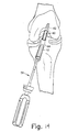
- FIG. 1 A cross-sectional view of the preferred interference screw usable with the present invention is the tapered bioabsorbable interference screw 10 as shown in Fig. 1.
- Screw 10 is formed of a bioabsorbable material, such as PLA or PLDLA (Poly(L/D-lactide)Acid), and may be provided in a variety of lengths, with 35 mm being preferred.
- Screw 10 has a main body portion 15, a proximal end 20, and a distal end 25, with threads 16 extending substantially from proximal end 20 to distal end 25. The edges 17 of the thread(s) 16 are flattened to prevent severing tissue during screw insertion.
- screw 10 is also provided with a cannula 30 extending centrally therethrough.
- the proximal end 20 of screw 10 is provided with an elongated socket 35 configured to receive the torque driver of the present invention, as will be described below.
- Socket 35 is preferably hexagonal in cross-section along the length thereof, and is furthermore formed, at least at the proximal portion thereof, with radially-extending slots 40 at every other annular face of socket 35.
- the slots 40 receive correspondingly-shaped protrusions 42 (as best seen in Fig. 5B) on the proximal end of the drive head of the driver.
- the delta-shaped drive socket 35 permits increased torque capacity while minimizing the problem of stripping the drive portion of the screw 10.
- the drive socket can also be used with a driver having a traditional hex drive head.
- screw 10 is tapered.
- the taper is a complex taper with an initial portion 45 at an angle of about 27°with respect to the longitudinal axis 50, an intermediate portion 55 at an angle of about 12° angle with respect to axis 50, and an elongated main body 15 with a more gradual taper.
- the relatively pointed distal portion 45 forms a nose that provides for easy insertion of the screw 10 into a bone tunnel.
- the interference screw of the present invention is provided in four sizes: (1) a screw which tapers from a 7.5 mm diameter at its tip to 9 mm. at the socket; (2) a screw which tapers from a 8.5 mm diameter at its tip to 10 mm. at the socket; (3) a screw which tapers from a 9.5 mm diameter at its tip to 11 mm at the socket; and (4) a screw which tapers from a 9.5 mm diameter at its tip to 12 mm at the socket.
- the screw As screw 10 threadingly advances through a bone tunnel, the screw dilates bone outwardly around the bone tunnel and creates an interference fit therewith.
- the tapered body of the screw permits the use of a smaller tunnel, as compared with non-tapered bone screws.
- the taper also causes a wedge effect that allows a large-diameter screw to be used in relation to the bone tunnel and graft size.
- the interference screw is sized to promote about a 1.5 mm interference fit; i.e ., so that the diameter of the proximal end 20 of the screw 15 is 1.5 mm larger than the diameter of the bone tunnel.
- Typical bone screws, which are not tapered provide a maximum of 1.0 mm interference fit. The additional interference provides 28% more pull out strength.
- Screw 10 is configured to be sufficiently long so as to fill all but the top 5-10 mm of the tibial bone tunnel. This configuration secures a large portion of the ligament graft against the bone tunnel while also providing threading engagement of the threads 16 of screw 10 against cortical bone at outer end of the bone tunnel. Because cortical bone is significantly harder than the interior soft, cancellous core, cortical bone provides significantly more load bearing capability. As a result, proper use of the interference screw described herein eliminates the need for multiple, shorter interference screws in a bone tunnel.
- Figs. 5A and 5B show a prior art driver 56 for inserting interference screw 10.
- Driver 56 has a handle and a drive shaft with an elongated hexagonally shaped drive head 58 forming the distal portion of the shaft.
- the hexagonal drive head is best shown in the magnified view illustrated in Fig. 5B, and is provided with protrusion 42 to mate with the delta-shaped drive recess 35 of screw 10.
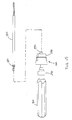
- Torque driver 100 is an improvement over the prior art driver, and is shown in exploded Fig. 6.
- Fig. 7 is an elevational view of the torque driver
- Fig. 8 is a cross-sectional view of the torque driver.
- Torque driver 100 generally includes a handle 110, a drive shaft 120 and a drive head 130, as in the prior art driver, and further includes a collar 140, a sleeve 150 and a torque assembly 200.
- handle 110 has axial grooves 112 (Fig. 6) and a central bore 111 extending through the length of the handle for receiving a guidewire therethrough (so as to be usable with the optionally cannulated interference screw).
- Central bore 111 has three distinct segments each of constant diameter along its respective length.
- First segment 114 extends from opening 113a at the proximal end of the handle 110 to approximately three-quarters of the length of the bore 111. Adjoining the distal end of segment 114, the diameter of bore 111 increases to that of second segment 116 via a radially outwardly tapered region 115.
- the diameter of bore 111 increases further to that of third segment 118 via a stepped shoulder 117.
- Third segment 118 extends to the opening 113b at the distal end of handle 110.
- a small hole 119 is formed at the distal portion of handle 110 from the outer surface of the handle extending into third segment 118 to accommodate insertion of a press fit pin (not shown), the purpose of which will be described later.
- the diameter of the second segment 116 is slightly larger than the outer diameter of collar 140 so as to receive collar 140 with sufficient room for rotation therein, but smaller than the outer diameter of sleeve 150.
- the diameter of the third segment 118 is sized to receive sleeve 150 therein.
- shaft 120 has a cannula extending through the length thereof to allow a guide wire to be threaded therethrough, and further includes a proximal portion 124 (Fig. 6) having a reduced diameter relative to the main portion 128 thereof, and a drive head 130 at the distal end thereof.
- the drive head 130 includes an elongated hexagonally shaped shaft at its distal end and having protrusions to mate with the drive recess of the bio-interference screw.
- the cannula extending centrally through shaft 120 also extends through the distal tip of drive head 130 to accommodate a guide wire.
- the inner diameter of sleeve 150 is sufficiently larger than the outer diameter of the main portion 128 of drive shaft 120 to enable the shaft to rotate freely therein, while the outer diameter of sleeve 150 is sized to be fitted in the third segment 118 of cannula 111.
- Collar 140 has an inner diameter sized to be fitted over the reduced diameter portion 124 of shaft 120, and an outer diameter which enables collar 140 to be rotated in second segment 116 of cannula 111 without frictional resistance.
- Torque assembly 200 includes a proximal cup 170 and an distal cup 180 encasing a torque spring 160 and a guide pin 190.
- Torque spring 160 is a coil spring in which the coil ends are bent to form two legs 162, 164 extending parallel to the coil axis in opposite directions away from the coiled body 166.
- proximal cup 170 is formed as an integral unit having a main body 171, stem 172 formed on one side of main body 171, outer cylindrical wall 173 formed on the opposite side of main body 171, inner cylindrical wall 174 formed opposite to stem 172 on the same side of main body 171 as outer cylindrical wall 173, and shoulder 175 formed between outer cylindrical wall 173 and the circumferential edge of main body 171.
- Main body 171 forms an annular channel 176 between outer cylindrical wall 173 and inner cylindrical wall 174.
- the outer diameter of channel 176 (adjacent to outer cylindrical wall 173) is sized to accommodate a torque spring 160 when in a resting state (with no load applied), while the inner diameter of channel 176 (adjacent to inner cylindrical wall 174) is no greater than the inner diameter of torque spring 160 when tightened to the greatest extent to be expected during use of the torque driver of the present invention.
- a cannula 177 extends centrally through stem 172, main body 171, and inner cylindrical wall 174, and has a diameter corresponding to the outer diameter of sleeve 150.
- a hole 178 is formed in main body 174 and extends from the bottom of channel 176 and preferably, though not necessarily, through the entire thickness of main body 171 to an opening at the opposite side thereof.
- Hole 178 extends parallel to cannula 177 and is radially positioned along the outer circumference of channel 176 adjacent to outer cylindrical wall 173.
- the diameter of hole 178 is sized to receive end leg 162 of torque spring 160.
- drainage holes 178a may also be formed in channel 176 which extend through the thickness of main body 171 to reduce the weight of the torque assembly 200.
- a hole 179 is formed on the distal surface of inner cylindrical wall 174 and has a diameter sized to engage a guide pin 190, the purpose of which will be discussed later.
- distal cup 180 of torque assembly 200 is formed as an integral unit having a main body 181, a stem 182 formed on one side of main body 181, outer cylindrical wall 183 formed on the opposite side of main body 181, inner cylindrical wall 184 formed opposite to stem 182 on the same side of main body 181 as outer cylindrical wall 183.
- Main body 181 forms an annular channel 186 between outer cylindrical wall 183 and inner cylindrical wall 184.
- the outer diameter of channel 186 (adjacent to outer cylindrical wall 183) is sized to accommodate insertion of outer cylindrical wall 173 of proximal cup 170, while the inner diameter of channel 186 (adjacent to inner cylindrical wall 174) is no greater than the inner diameter of torque spring 160 when tightened to the greatest extent to be expected during use of the torque driver of the present invention.
- a cannula 187 extends centrally through stem 182, main body 181, and inner cylindrical wall 184, and has a diameter corresponding to the outer diameter of the main portion 128 of shaft 120.
- a hole 188 is formed in main body 184 in channel 186 and preferably, though not necessarily, extends through the entire thickness of main body 181 to an opening at the opposite side thereof.
- Hole 188 extends parallel to cannula 187 and has a diameter sized to receive end leg 164 of torque spring 160.
- hole 188 is radially positioned in channel 186 to receive the spring end when the other spring end is inserted into hole 178 of proximal cup 170 and torque spring 160 is at rest (with no load applied).
- drainage holes 185 may also be formed in channel 186 which extend through the thickness of main body 171 to reduce the weight of the torque assembly 200.
- An arcuate groove 189 is formed on the proximal surface of inner cylindrical wall 184 and has a width sized to accommodate guide pin 190.
- the arcuate range of groove 189 corresponds with a maximum range of rotation to be allowed between proximal cup 170 and distal cup 180 of torque assembly 200.
- the maximum range of rotation corresponds with the maximum expected or allowed torque to be applied using the torque driver, taking into consideration the torsional resistance of torque spring 160.
- proximal and distal cups 170 and 180 have cooperating indicia for indicating an amount of torque exerted on torque spring 160 between the cups 170, 180.
- Distal cup 180 is marked with a scale 220 corresponding to a torque range from 0 to a predetermined maximum quantity. The spacing between scale markings is calibrated according to the spring constant of spring 160, while the arcuate range covered by the scale corresponds that of groove 189.
- Proximal cup 170 has a singular reference mark 210 for indicating the torque measurement against scale 220.
- proximal cup 170 and distal cup 180 the height of the respective outer cylindrical wall 173, 183 is greater than the respective inner cylindrical wall 174, 184 as measured from the base of channel 176,186 so that when the proximal and distal cups are assembled to form the torque assembly 200, the proximal surface of outer cylindrical wall 183 in distal cup 180 abuts against shoulder 175 on proximal cup 170 while the distal surface of inner cylindrical wall 174 abuts against the proximal surface of inner cylindrical wall 184.
- shaft 120 is inserted through cannula 187 of distal cup 180 of torque assembly 200 so that a length of the main shaft portion 128 (not including the reduced diameter proximal portion 124) corresponding to the length of the sleeve 150 extends proximally from the distal cup 180.
- Distal cup 180 is then welded or brazed to the shaft 120 at this position along the length thereof.
- Sleeve 150 is inserted into cannula 177 of proximal cup 170 until the distal end thereof is flush with the distal surface of inner cylindrical wall 174, so as to also abut the proximal surface of inner cylindrical wall 184 of distal cup 180. In this position, sleeve 150 is affixed to stem 172 of proximal cup 170 by welding or brazing. Alternatively, sleeve 150 and proximal cup 170 may be formed as an integral piece. The proximal end of shaft 120 is then inserted into the proximal cup 170 and sleeve 150.
- the torque assembly 200 is assembled by press fitting the guide pin 190 into hole 179 in proximal cup 170, placing torque spring 160 into annular channel 176 of proximal cup 170 with leg 162 inserted into hole 178, and inserting leg 164 of spring 160 into hole 188 in distal cup 180.
- Torque assembly 200 is closed by inserting outer cylindrical wall 173 of proximal cup 170 into annular channel 186 inside outer cylindrical wall 183 of distal cup 180, whereupon guide pin 190 should become inserted into end 189a of groove 189 and torque spring 160 becomes encased between annular channels 176 and 186.
- the assembled unit is then inserted into handle 110, with the proximal surface of collar 140 inserted into stepped bore section 116 and abutting only the radially outermost edge of taper section 115.
- the minimized contact area between the collar 140 and handle 110 enables the collar 140 and hence shaft 120 to rotate freely within the stepped bore sections 116 and 118.
- Sleeve 150 is fixed relative to the handle 110 by a fixing pin inserted into hole 119 in handle 110 and hole 152 in sleeve 150.
- the method of endosteal fixation of a ligament graft using an interference screw in accordance with the present invention includes the steps of securing one end of a graft 60 in the femoral socket 62, pulling the opposite end of the graft 60 (extending through the tibial tunnel) taut, and fixating the graft 60 in the tibial tunnel 64 by mounting the bioabsorbable interference screw 10 on torque driver 100 and, using the driver, driving screw 10 in the tibial tunnel against graft 60 to the level of the anterior cortex in the distal portion of the tibial tunnel, such that the interference screw fills all but the top 5-10 mm. of the tunnel, while measuring the torque being applied using the measurement scale 220.
- the resistance met by the interference screw in entering the tunnel causes the torque spring 160 to tighten.
- the amount of force from the handle absorbed by the torque assembly to tighten the torque spring depends on the friction resistance between the interference screw and the bone tunnel, and also the spring constant of the coil spring 160.
- the greater the frictional resistance the more the coil spring 160 is tightened as the torque exerted on the handle is tightened.
- the spring constant i.e., the resistance of the spring against being tightened
- the spring incorporated into the driver of the present invention is selected so as to be able to tightened through a measurable arcuate distance when a torque force in the range yielding a desired fixation strength is achieved.
- the measurement mark 210 is aligned with the "0" mark on the scale 220, and the guide pin 190 is positioned at end 189a of groove 189.
- the measurement mark 210 is aligned with the "0" mark on the scale 220, and the guide pin 190 is positioned at end 189a of groove 189.
- the guide pin 190 travels to end 189b of groove 189 in distal cup 180, and prevents further relative rotation between the proximal and distal cups.
- the measurement marking 210 is prevented from indicating a torque quantity greater than the predetermined amount, thus signaling to the operator that the maximum allowable torque has been reached and enabling the operator to avoid overtorqueing the anchor. If this point is reached, it is possible that a smaller diameter interference screw may be warranted, or that the diameter of the bone tunnel should be increased.
- the fixation strength of the interference screw will be insufficient for proper healing. In this situation, the surgeon should then either replace the interference screw with another having a larger diameter or install a backup fixation device to supplement the fixation strength provided by the interference screw.
- driver 66 is then removed, leaving screw 10 in place with an interference fit of up to 1.5 mm, whereupon the surgeon can be confident that the interference screw has been applied with a predetermined amount of torque to optimize the fixation strength of the screw.
- the hole 179 and guide pin 190 are shown radially inward of the spring body 160, but may be positioned radially outward therefrom instead. In further alternatives, other stopping conventions also may be employed without departing from the spirit of the invention.
- the torque driver can be constructed so that the shaft is releasable so as to be interchangeable, to enable use of the driver with different types of tissue anchor or interference screws.
- An example of a torque assembly usable in this embodiment is shown in Fig. 15.
- the distal side of the distal cup 380 includes a male of female connection socket 350 for releasably engaging a mating connection structure 340 at the proximal end of a drive shaft 320, and the proximal portion of the torque assembly 300 is mountable in the driver handle 310 with a quick-connect fitting 390.
- a ratchet handle which only allows an operator to apply torque in one direction.
- This feature may be implemented according to standard ratcheting mechanisms known to those of ordinary skill in the art, and may be used in combination with the quick-connect feature of the torque assembly and releasable drive shaft construction.
- a tapered, bioabsorbable interference screw is used in connection with the present invention to optimize the fixation strength of the tissue to the bone.
- the torque driver may be used in the same manner as described herein to install other types of fixation screws such as a conventional, non-tapered interference screw or a headed tissue anchor to secure soft tissue to a bone.
- fixation screws such as a conventional, non-tapered interference screw or a headed tissue anchor to secure soft tissue to a bone.
- the drive head at the distal end of the torque driver would be appropriately modified or constructed to drivingly engage the selected fixation device.
Abstract
Description
- This application claims the benefit of U.S. Provisional Application No. 60/270,865, filed February 26, 2001, the disclosure of which is herein incorporated by reference.
- The present invention relates to instrumentation used for endosteal fixation of a substitute ligament and, more specifically, to a driver for inserting a tapered bioabsorbable interference screw to perform soft tissue attachment to bone such as arthroscopic endosteal fixation of a substitute anterior cruciate ligament.
- When a ligament becomes detached from a bone, surgery usually is required to reconstruct the ligament. Often, a substitute ligament or graft is secured into bone tunnels to facilitate incorporation and permanent attachment. It is critical that the reattached tissue or the tissue graft be sufficiently secured to withstand the normal loads to which they may be subjected, e.g., those imposed by a patient on the affected joint or region.
- Various methods of graft attachment are known, including the use of interference screws to secure the graft against the walls of a tunnel drilled through the tibia and a socket formed in the femur. A strong graft attachment is obtained by using a metal interference screw to wedge a graft bone block to the wall of a graft tunnel formed through the bone, as disclosed in U.S. Patent No. 5,211,647 to Schmieding. If a bioabsorbable interference screw is used, the graft is often wedged directly against the bone by the screw, without a bone block.
- Bioabsorbable interference screws are usually sized so that they are slightly larger than the diameter of the tunnel, so that they dilate the bone tunnel upon insertion. Dilation advantageously compacts the soft cancellous bone between the ends of the tunnel, providing better fixation. Conventional straight-sided bioabsorbable interference screws have an interference fit of about 1mm. meaning that about 1 mm of bone is dilated as the screw is inserted into the bone tunnel.
- Recent tests have determined that a relationship exists between screw insertion torque and graft fixation strength when inserting interference screws. As disclosed in the study entitled "Correlation of Insertion Torque, Load at Failure and Bone Density Utilizing a Soft Tissue Interference Screw with Free Central Quadriceps Tendon Graft in ACL Reconstruction," presented at the 1999 International Society of Arthroscopy, Knee Surgery and Orthopedic Sports Medicine Congress by J.P. Fulkerson et al., the correlation of insertion torque to peak load at failure was calculated to be 0.86, and that the fixation strength achieved in each instance in which the insertion torque was greater than 14.5 in/lbs. resulted in a peak load greater than 315 N at failure.
- Greater insertion torque can be achieved by increasing the resistance of the interference screw being inserted into the tunnel. Thus, a larger diameter screw relative to the diameter of the bone tunnel provides greater dilation and a greater interference fit, and therefore increased fixation strength. Some larger, conventionally-shaped interference screws, however, have larger tips and are more difficult to align and insert correctly. One example of a bioabsorbable interference screw which provides increased dilation and interference fit without increased difficulty of insertion is disclosed in pending U.S. Patent Application Serial No. 09/711,964 filed November 15, 2000 and entitled "Tapered Bioabsorbable Interference Screw for Endosteal Fixation of Ligaments," the disclosure of which is herein incorporated by reference.
- In light of the recently discovered correlation between insertion force and fixation strength, it would be beneficial if surgeons could determine the amount of force being exerted during insertion of the interference screw or otherwise directly assess the amount of fixation strength provided by the inserted interference screw. If a graft is secured with insufficient fixation strength to withstand expected loads, the patient may experience a limited recovery of the affected joint at best, and may suffer re-injury or separation of the graft from the bone. On the other hand, if too much force is applied to the interference screw during fixation, the bone may become overstressed, resulting in cracks or other damage. Currently, however, no method is available to quantify the torque force exerted during insertion of the interference screw, or to otherwise determine whether or not an acceptable range of fixation strength has been achieved.
- The present invention fills the void in the prior art by providing a torque driver which can measure the amount of torque being applied during implanting the screw. The torque driver according to the present invention is similar to a standard driver known in the art having a handle, drive shaft and drive head, a sleeve disposed around the proximal portion of the shaft, and further includes a torque measurement assembly connected between the handle and the sleeve.
- The torque measurement assembly includes a proximal cup and a distal cup, and a coil spring encased between the cups, with one end of the spring fixed in the proximal cup and the other end of the spring fixed in the distal cup. The proximal cup is fixed to the distal end of the sleeve, and the proximal portion of the sleeve is fixed in the handle. The distal cup is fixed to the drive shaft, which rotates freely within the sleeve. Thus, the drive shaft and distal cup move together as one unit while the handle, sleeve, and proximal cup move together as one unit. The two units are physically connected to each other only by the torque spring.
- When the torque driver is used to insert an interference screw, the driver head is inserted into the socket of the screw and the driver is turned, the rotational force exerted to drive the screw causes the torque spring to tighten. A torque scale is marked on one of the proximal and distal cups in accordance with the resistance of the torque spring, while a reference marking is provided on the other. As the spring tightens, the reference mark moves along the scale to indicate the torque measurement exerted on the spring.
- Since the torque exerted to drive an interference screw into bone is related to the resistance met by the screw in entering the bone, using the present invention, a surgeon can be confident that a desired minimum torque load is being applied which translates to a correspondingly desirable level of fixation strength for the graft. The surgeon is made aware if inadequate fixation strength is measured during fixation of the screw, whereupon backup fixation devices are indicated and can be implanted to secure the graft, or alternatively, an interference screw having a larger diameter can be used instead . Also, the surgeon is made aware if too much torque is being exerted, which creates a risk of splitting or otherwise damaging the bone at the fixation site.
- Preferably, though not necessarily, the interference screw used with the present invention is a tapered, elongated bioabsorbable interference screw, the taper of the screw extending along substantially the entire length of the elongated threaded screw. The taper of the bioabsorbable interference screw of the present invention advantageously facilitates insertion of the tip of the screw, while providing superior fixation resulting from an enlarged back end. Upon insertion, the bioabsorbable interference screw of the present invention fills all but 5-10 mm. of the tunnel, thereby providing increased fixation strength while also promoting healing.
- Additionally, the preferred interference screw used in conjunction with the present invention includes a head provided with a specially designed Delta drive socket for receiving a Delta drive screwdriver or a traditional hex-head screwdriver. The unique driver socket of the interference screw of the present invention optimizes the torque capacity of the screw. To maintain wall thickness, the drive socket may be tapered in correspondence with the tapered outer profile of the device. The taper also permits easy insertion of the tip and shaft of the Delta driver or hex driver (also tapered if screw drive socket is tapered) into the fixation screw.
- The tapered bioabsorbable interference screw usable with the present invention is threaded along substantially the entire length of the screw to maximize fixation strength within the tunnel and is preferably, formed of highly crystalline poly-(L-lactic acid) (PLLA) compound. Also, the distal end of the screw, i.e., the end closest to the joint, has a smooth, rounded tip profile so as to minimize abrasion with the graft.
- Optionally, the torque driver and interference screw in accordance with the present invention may be both cannulated for insertion over a guide pin. According to this aspect of the invention, the guide pin is inserted through the cannula of the driver and the interference screw, and into the bone tunnel, to thereby guide the interference screw during delivery and installation.
- In an exemplary method of ACL reconstruction of the present invention, the graft, such as a hamstring tendon autograft or allograft, is secured by interference screw fixation in a femoral socket formed through the tibial tunnel, as described, for example, in U.S. Patent No. 5,320,626, the disclosure of which is incorporated herein. The hamstring graft is then drawn taut and secured in the tibial tunnel by insertion of the interference screw using the torque driver of the present invention.
- Other features and advantages of the present invention will become apparent from the following description of the invention which refers to the accompanying drawings.
-
- Fig. 1 is a cross-sectional detail view, drawn along line A-A of Fig. 2, of the tapered bioabsorbable interference screw of the present invention;
- Fig. 2 is a rear elevational view of the tapered bioabsorbable interference screw of the present invention;
- Fig. 3 is a cross-sectional detail view, drawn along line C-C of Fig. 2, of the interference screw of the present invention;
- Fig. 4 a cross-sectional detail view, drawn along line D-D of Fig. 2, of the interference screw of the present invention;
- Fig. 5A is a side view of the interference screw driver and Fig. 5B is a detailed view of the tip of the driver;
- Fig. 6 is an exploded perspective view of a torque driver in accordance with the present invention.
- Fig. 7 is a side elevational view of the torque driver of Fig. 6.
- Fig. 8 is an axial cross-sectional view of the torque driver of Fig. 6.
- Fig. 9 is an axial cross-sectional view of the handle of the torque driver of Fig. 6.
- Fig. 10 is a cross-sectional view of the proximal cup of the torque assembly in the torque driver.
- Fig. 11 is a distal elevational view of the proximal cup of the torque assembly.
- Fig. 12 is a cross-sectional view of the distal cup of the torque assembly in the torque driver.
- Fig. 13 is a distal elevational view of the distal cup of the torque assembly.
- Fig. 14 shows the interference screw of the present invention being inserted into the tibial tunnel against a ligament graft.
- Fig. 15 shows a drive shaft which is releasable from a the torque assembly in a variant of the present invention.
- Figs. 16-19 show a quick-connect torque assembly which may be incorporated in the variant of the torque driver of the present invention.
- Fig. 20 shows a ratchet handle which may be used in combination with the quick-connect torque assembly feature in a further variant of the present invention.
-
- A cross-sectional view of the preferred interference screw usable with the present invention is the tapered
bioabsorbable interference screw 10 as shown in Fig. 1.Screw 10 is formed of a bioabsorbable material, such as PLA or PLDLA (Poly(L/D-lactide)Acid), and may be provided in a variety of lengths, with 35 mm being preferred.Screw 10 has amain body portion 15, aproximal end 20, and adistal end 25, withthreads 16 extending substantially fromproximal end 20 todistal end 25. Theedges 17 of the thread(s) 16 are flattened to prevent severing tissue during screw insertion. Preferably, screw 10 is also provided with acannula 30 extending centrally therethrough. - Referring now to Fig. 2, the
proximal end 20 ofscrew 10 is provided with anelongated socket 35 configured to receive the torque driver of the present invention, as will be described below.Socket 35 is preferably hexagonal in cross-section along the length thereof, and is furthermore formed, at least at the proximal portion thereof, with radially-extendingslots 40 at every other annular face ofsocket 35. Theslots 40 receive correspondingly-shaped protrusions 42 (as best seen in Fig. 5B) on the proximal end of the drive head of the driver. The delta-shapeddrive socket 35 permits increased torque capacity while minimizing the problem of stripping the drive portion of thescrew 10. Advantageously, the drive socket can also be used with a driver having a traditional hex drive head. - As shown in Figs. 1 and 3, screw 10 is tapered. The taper is a complex taper with an
initial portion 45 at an angle of about 27°with respect to thelongitudinal axis 50, anintermediate portion 55 at an angle of about 12° angle with respect toaxis 50, and an elongatedmain body 15 with a more gradual taper. The relatively pointeddistal portion 45 forms a nose that provides for easy insertion of thescrew 10 into a bone tunnel. - The interference screw of the present invention is provided in four sizes: (1) a screw which tapers from a 7.5 mm diameter at its tip to 9 mm. at the socket; (2) a screw which tapers from a 8.5 mm diameter at its tip to 10 mm. at the socket; (3) a screw which tapers from a 9.5 mm diameter at its tip to 11 mm at the socket; and (4) a screw which tapers from a 9.5 mm diameter at its tip to 12 mm at the socket.
- As
screw 10 threadingly advances through a bone tunnel, the screw dilates bone outwardly around the bone tunnel and creates an interference fit therewith. The tapered body of the screw permits the use of a smaller tunnel, as compared with non-tapered bone screws. The taper also causes a wedge effect that allows a large-diameter screw to be used in relation to the bone tunnel and graft size. Preferably, the interference screw is sized to promote about a 1.5 mm interference fit; i.e., so that the diameter of theproximal end 20 of thescrew 15 is 1.5 mm larger than the diameter of the bone tunnel. Typical bone screws, which are not tapered, provide a maximum of 1.0 mm interference fit. The additional interference provides 28% more pull out strength. -
Screw 10 is configured to be sufficiently long so as to fill all but the top 5-10 mm of the tibial bone tunnel. This configuration secures a large portion of the ligament graft against the bone tunnel while also providing threading engagement of thethreads 16 ofscrew 10 against cortical bone at outer end of the bone tunnel. Because cortical bone is significantly harder than the interior soft, cancellous core, cortical bone provides significantly more load bearing capability. As a result, proper use of the interference screw described herein eliminates the need for multiple, shorter interference screws in a bone tunnel. - Figs. 5A and 5B show a
prior art driver 56 for insertinginterference screw 10.Driver 56 has a handle and a drive shaft with an elongated hexagonallyshaped drive head 58 forming the distal portion of the shaft. The hexagonal drive head is best shown in the magnified view illustrated in Fig. 5B, and is provided withprotrusion 42 to mate with the delta-shapeddrive recess 35 ofscrew 10. - The
torque driver 100 according to the present invention is an improvement over the prior art driver, and is shown in exploded Fig. 6. Fig. 7 is an elevational view of the torque driver, while Fig. 8 is a cross-sectional view of the torque driver.Torque driver 100 generally includes ahandle 110, adrive shaft 120 and adrive head 130, as in the prior art driver, and further includes acollar 140, asleeve 150 and atorque assembly 200. - As shown in Fig. 9, handle 110 has axial grooves 112 (Fig. 6) and a central bore 111 extending through the length of the handle for receiving a guidewire therethrough (so as to be usable with the optionally cannulated interference screw). Central bore 111 has three distinct segments each of constant diameter along its respective length.
First segment 114 extends from opening 113a at the proximal end of thehandle 110 to approximately three-quarters of the length of the bore 111. Adjoining the distal end ofsegment 114, the diameter of bore 111 increases to that of second segment 116 via a radially outwardly taperedregion 115. Adjoining the distal end of segment 116, the diameter of bore 111 increases further to that of third segment 118 via a steppedshoulder 117. Third segment 118 extends to the opening 113b at the distal end ofhandle 110. Asmall hole 119 is formed at the distal portion ofhandle 110 from the outer surface of the handle extending into third segment 118 to accommodate insertion of a press fit pin (not shown), the purpose of which will be described later. - The diameter of the second segment 116 is slightly larger than the outer diameter of
collar 140 so as to receivecollar 140 with sufficient room for rotation therein, but smaller than the outer diameter ofsleeve 150. Similarly, the diameter of the third segment 118 is sized to receivesleeve 150 therein. - As can be seen in Fig. 8,
shaft 120 has a cannula extending through the length thereof to allow a guide wire to be threaded therethrough, and further includes a proximal portion 124 (Fig. 6) having a reduced diameter relative to themain portion 128 thereof, and adrive head 130 at the distal end thereof. As in the prior art driver, thedrive head 130 includes an elongated hexagonally shaped shaft at its distal end and having protrusions to mate with the drive recess of the bio-interference screw. The cannula extending centrally throughshaft 120 also extends through the distal tip ofdrive head 130 to accommodate a guide wire. - The inner diameter of
sleeve 150 is sufficiently larger than the outer diameter of themain portion 128 ofdrive shaft 120 to enable the shaft to rotate freely therein, while the outer diameter ofsleeve 150 is sized to be fitted in the third segment 118 of cannula 111. -
Collar 140 has an inner diameter sized to be fitted over the reduceddiameter portion 124 ofshaft 120, and an outer diameter which enablescollar 140 to be rotated in second segment 116 of cannula 111 without frictional resistance. -
Torque assembly 200 includes aproximal cup 170 and andistal cup 180 encasing atorque spring 160 and aguide pin 190. -
Torque spring 160 is a coil spring in which the coil ends are bent to form twolegs - Referring now to Figs. 10-11,
proximal cup 170 is formed as an integral unit having amain body 171, stem 172 formed on one side ofmain body 171, outercylindrical wall 173 formed on the opposite side ofmain body 171, innercylindrical wall 174 formed opposite to stem 172 on the same side ofmain body 171 as outercylindrical wall 173, andshoulder 175 formed between outercylindrical wall 173 and the circumferential edge ofmain body 171. -
Main body 171 forms anannular channel 176 between outercylindrical wall 173 and innercylindrical wall 174. The outer diameter of channel 176 (adjacent to outer cylindrical wall 173) is sized to accommodate atorque spring 160 when in a resting state (with no load applied), while the inner diameter of channel 176 (adjacent to inner cylindrical wall 174) is no greater than the inner diameter oftorque spring 160 when tightened to the greatest extent to be expected during use of the torque driver of the present invention. - A
cannula 177 extends centrally throughstem 172,main body 171, and innercylindrical wall 174, and has a diameter corresponding to the outer diameter ofsleeve 150. - A
hole 178 is formed inmain body 174 and extends from the bottom ofchannel 176 and preferably, though not necessarily, through the entire thickness ofmain body 171 to an opening at the opposite side thereof.Hole 178 extends parallel tocannula 177 and is radially positioned along the outer circumference ofchannel 176 adjacent to outercylindrical wall 173. The diameter ofhole 178 is sized to receiveend leg 162 oftorque spring 160. Optionally,drainage holes 178a may also be formed inchannel 176 which extend through the thickness ofmain body 171 to reduce the weight of thetorque assembly 200. - A
hole 179 is formed on the distal surface of innercylindrical wall 174 and has a diameter sized to engage aguide pin 190, the purpose of which will be discussed later. - As illustrated in Figs. 12-13,
distal cup 180 oftorque assembly 200 is formed as an integral unit having amain body 181, astem 182 formed on one side ofmain body 181, outercylindrical wall 183 formed on the opposite side ofmain body 181, innercylindrical wall 184 formed opposite to stem 182 on the same side ofmain body 181 as outercylindrical wall 183. -
Main body 181 forms anannular channel 186 between outercylindrical wall 183 and innercylindrical wall 184. The outer diameter of channel 186 (adjacent to outer cylindrical wall 183) is sized to accommodate insertion of outercylindrical wall 173 ofproximal cup 170, while the inner diameter of channel 186 (adjacent to inner cylindrical wall 174) is no greater than the inner diameter oftorque spring 160 when tightened to the greatest extent to be expected during use of the torque driver of the present invention. - A
cannula 187 extends centrally throughstem 182,main body 181, and innercylindrical wall 184, and has a diameter corresponding to the outer diameter of themain portion 128 ofshaft 120. - A
hole 188 is formed inmain body 184 inchannel 186 and preferably, though not necessarily, extends through the entire thickness ofmain body 181 to an opening at the opposite side thereof.Hole 188 extends parallel tocannula 187 and has a diameter sized to receiveend leg 164 oftorque spring 160. Additionally,hole 188 is radially positioned inchannel 186 to receive the spring end when the other spring end is inserted intohole 178 ofproximal cup 170 andtorque spring 160 is at rest (with no load applied). Optionally, drainage holes 185 may also be formed inchannel 186 which extend through the thickness ofmain body 171 to reduce the weight of thetorque assembly 200. - An
arcuate groove 189 is formed on the proximal surface of innercylindrical wall 184 and has a width sized to accommodateguide pin 190. The arcuate range ofgroove 189 corresponds with a maximum range of rotation to be allowed betweenproximal cup 170 anddistal cup 180 oftorque assembly 200. The maximum range of rotation, in turn, corresponds with the maximum expected or allowed torque to be applied using the torque driver, taking into consideration the torsional resistance oftorque spring 160. - As can be seen in Fig. 7, proximal and
distal cups torque spring 160 between thecups Distal cup 180 is marked with ascale 220 corresponding to a torque range from 0 to a predetermined maximum quantity. The spacing between scale markings is calibrated according to the spring constant ofspring 160, while the arcuate range covered by the scale corresponds that ofgroove 189.Proximal cup 170 has asingular reference mark 210 for indicating the torque measurement againstscale 220. - In each of
proximal cup 170 anddistal cup 180, the height of the respective outercylindrical wall cylindrical wall torque assembly 200, the proximal surface of outercylindrical wall 183 indistal cup 180 abuts againstshoulder 175 onproximal cup 170 while the distal surface of innercylindrical wall 174 abuts against the proximal surface of innercylindrical wall 184. - In the assembled state of the
torque driver 100,shaft 120 is inserted throughcannula 187 ofdistal cup 180 oftorque assembly 200 so that a length of the main shaft portion 128 (not including the reduced diameter proximal portion 124) corresponding to the length of thesleeve 150 extends proximally from thedistal cup 180.Distal cup 180 is then welded or brazed to theshaft 120 at this position along the length thereof. -
Sleeve 150 is inserted intocannula 177 ofproximal cup 170 until the distal end thereof is flush with the distal surface of innercylindrical wall 174, so as to also abut the proximal surface of innercylindrical wall 184 ofdistal cup 180. In this position,sleeve 150 is affixed to stem 172 ofproximal cup 170 by welding or brazing. Alternatively,sleeve 150 andproximal cup 170 may be formed as an integral piece. The proximal end ofshaft 120 is then inserted into theproximal cup 170 andsleeve 150. - Next, the
torque assembly 200 is assembled by press fitting theguide pin 190 intohole 179 inproximal cup 170, placingtorque spring 160 intoannular channel 176 ofproximal cup 170 withleg 162 inserted intohole 178, and insertingleg 164 ofspring 160 intohole 188 indistal cup 180.Torque assembly 200 is closed by inserting outercylindrical wall 173 ofproximal cup 170 intoannular channel 186 inside outercylindrical wall 183 ofdistal cup 180, whereuponguide pin 190 should become inserted intoend 189a ofgroove 189 andtorque spring 160 becomes encased betweenannular channels torque assembly 200 is closed, the distal surface of innercylindrical wall 174 ofproximal cup 170 abuts the proximal surface of innercylindrical wall 184 ofdistal cup 180. Shaft 102 is then prevented by slipping out ofsleeve 150 by brazing orwelding collar 140 onto the reduceddiameter portion 124 at the proximal end ofshaft 120. - The assembled unit is then inserted into
handle 110, with the proximal surface ofcollar 140 inserted into stepped bore section 116 and abutting only the radially outermost edge oftaper section 115. The minimized contact area between thecollar 140 and handle 110 enables thecollar 140 and henceshaft 120 to rotate freely within the stepped bore sections 116 and 118. -
Sleeve 150 is fixed relative to thehandle 110 by a fixing pin inserted intohole 119 inhandle 110 and hole 152 insleeve 150. - Referring now to Fig. 14, the method of endosteal fixation of a ligament graft using an interference screw in accordance with the present invention includes the steps of securing one end of a
graft 60 in thefemoral socket 62, pulling the opposite end of the graft 60 (extending through the tibial tunnel) taut, and fixating thegraft 60 in thetibial tunnel 64 by mounting thebioabsorbable interference screw 10 ontorque driver 100 and, using the driver, drivingscrew 10 in the tibial tunnel againstgraft 60 to the level of the anterior cortex in the distal portion of the tibial tunnel, such that the interference screw fills all but the top 5-10 mm. of the tunnel, while measuring the torque being applied using themeasurement scale 220. - Since the
handle 110 is fixedly secured to thesleeve 150 by the fixing pin which in turn is fixedly secured toproximal cup 170, rotation of the handle causes thesleeve 150 and proximal cup to rotate with the same force exerted on thehandle 110. At least a portion of the driving force placed on the handle is transferred through thespring 160 and to thedistal cup 180 to ultimately drive the interference screw into the bone, since thedistal cup 180 is fixedly connected to theshaft 120, which is fixedly connected to thedrive head 130. As described above, rotation of theshaft 120 is not inhibited bysleeve 150 or bycollar 140 in segment 116 of cannula 111. - The resistance met by the interference screw in entering the tunnel causes the
torque spring 160 to tighten. The amount of force from the handle absorbed by the torque assembly to tighten the torque spring depends on the friction resistance between the interference screw and the bone tunnel, and also the spring constant of thecoil spring 160. The greater the frictional resistance, the more thecoil spring 160 is tightened as the torque exerted on the handle is tightened. In contrast, as the spring constant, i.e., the resistance of the spring against being tightened, increases, a greater portion of the rotational force placed on the handle is translated directly to turning theshaft 160 and drivehead 130. Thus, the spring incorporated into the driver of the present invention is selected so as to be able to tightened through a measurable arcuate distance when a torque force in the range yielding a desired fixation strength is achieved. - At rest, with no torque load exerted on the driver, the
measurement mark 210 is aligned with the "0" mark on thescale 220, and theguide pin 190 is positioned atend 189a ofgroove 189. When cups 170 and 180 are rotated relative to one another, rotational tension is exerted on the spring, whereupon the measurement of this force is indicated by the mark inscale 220 aligned withmeasurement mark 210 and corresponds to the amount of torque exerted onspring 160 betweencups - Greater rotational force exerted on
handle 110 causes spring 160 to tighten. Asspring 160 tightens, the spring exerts increasingly greater resistance to rotation. This resistance is measured as the torque force using themarkings - At the maximum torque load for which the torque driver is designed is reached, the
guide pin 190 travels to end 189b ofgroove 189 indistal cup 180, and prevents further relative rotation between the proximal and distal cups. At this point, the measurement marking 210 is prevented from indicating a torque quantity greater than the predetermined amount, thus signaling to the operator that the maximum allowable torque has been reached and enabling the operator to avoid overtorqueing the anchor. If this point is reached, it is possible that a smaller diameter interference screw may be warranted, or that the diameter of the bone tunnel should be increased. - If the highest measurement achieved during installation is less than a predetermined minimum, the fixation strength of the interference screw will be insufficient for proper healing. In this situation, the surgeon should then either replace the interference screw with another having a larger diameter or install a backup fixation device to supplement the fixation strength provided by the interference screw.
- After achieving a desired torque measurement or a torque measurement in the desired range using the present invention, driver 66 is then removed, leaving
screw 10 in place with an interference fit of up to 1.5 mm, whereupon the surgeon can be confident that the interference screw has been applied with a predetermined amount of torque to optimize the fixation strength of the screw. - In the preferred embodiment, the
hole 179 andguide pin 190 are shown radially inward of thespring body 160, but may be positioned radially outward therefrom instead. In further alternatives, other stopping conventions also may be employed without departing from the spirit of the invention. - Optionally, the torque driver can be constructed so that the shaft is releasable so as to be interchangeable, to enable use of the driver with different types of tissue anchor or interference screws. An example of a torque assembly usable in this embodiment is shown in Fig. 15. Specifically, the distal side of the
distal cup 380 includes a male offemale connection socket 350 for releasably engaging amating connection structure 340 at the proximal end of adrive shaft 320, and the proximal portion of thetorque assembly 300 is mountable in the driver handle 310 with a quick-connect fitting 390. - Another optional feature which may be provided in connection with the torque driver of the present invention is a ratchet handle, which only allows an operator to apply torque in one direction. This feature may be implemented according to standard ratcheting mechanisms known to those of ordinary skill in the art, and may be used in combination with the quick-connect feature of the torque assembly and releasable drive shaft construction.
- As described above, it is preferred that a tapered, bioabsorbable interference screw is used in connection with the present invention to optimize the fixation strength of the tissue to the bone. Alternatively, the torque driver may be used in the same manner as described herein to install other types of fixation screws such as a conventional, non-tapered interference screw or a headed tissue anchor to secure soft tissue to a bone. With other types of fixation devices, the drive head at the distal end of the torque driver would be appropriately modified or constructed to drivingly engage the selected fixation device.
- Although the present invention has been described in relation to particular embodiments thereof, many other variations and modifications and other uses will become apparent to those skilled in the art. It is preferred, therefore, that the present invention be limited not by the specific disclosure herein, but only by the appended claims.
Claims (20)
- A torque driver for driving an interference screw, comprising:a handle;a sleeve fixedly connected to the handle;a drive shaft having a drive head formed at the distal portion thereof, the proximal end of the drive shaft being covered by and rotatable in the sleeve; anda torque measurement assembly which includes a proximal cup fixedly connected to a sleeve, a distal cup fixedly connected t the drive shaft, and a coil spring encased between the proximal and distal cups, wherein one end of the coil spring is fixed in the proximal cup and the other end of the coil spring is fixed in the distal cup.
- The torque driver according to claim 1, wherein the torque measurement assembly further includes a stop for limiting further relative rotation between the proximal and distal cups at a position between the proximal and distal cups when the coil spring is tightened to a maximum level of tension.
- The torque driver according to claim 1, wherein the torque measurement assembly further includes at least one stop mechanism for limiting the relative range of rotation between the proximal and distal cups, the range corresponding to the position between the proximal and distal cups in a state in which no force is exerted on the spring, and the position between the proximal and distal cups when the coil spring is tightened to a maximum level of tension.
- The torque driver according to claim 3, wherein the stop mechanism is formed by an arcuate groove formed in one of the proximal and distal cups, and a guide pin fixed in the other of the proximal and distal cups so that the guide pin is guided along the arcuate groove during relative rotation between the proximal and distal cups.
- The torque driver according to claim 1, wherein one of the proximal and distal cups has a scale marked thereon and the other has a reference mark provided thereon for indicating a measurement of the torque being exerted during use of the driver.
- The torque driver according to claim 5, wherein the scale markings indicate a range corresponding to the position between the proximal and distal cups in a state in which no force is exerted on the spring, and the position between the proximal and distal cups when the coil spring is tightened to a maximum desirable level of tension.
- The torque driver according to claim 5, wherein the torque measurement assembly further includes a stop mechanism for limiting further relative rotation between the proximal and distal cups at a position between the proximal and distal cups when the coil spring is tightened to a maximum level of tension.
- The torque driver according to claim 7, wherein the stop mechanism is formed by an arcuate groove formed in one of the proximal and distal cups, and a guide pin fixed in the other of the proximal and distal cups so that the guide pin is guided along the arcuate groove during relative rotation between the proximal and distal cups.
- The torque driver according to claim 5, wherein the torque measurement assembly further includes at least one stop mechanism for limiting the relative range of rotation between the proximal and distal cups, the range corresponding to the maximum and minimum torque measurements indicated on the scale.
- The torque driver according to claim 1, wherein the drive head is an elongated hexagonally shaped shaft.
- The torque driver according to claim 1, wherein the drive head has radially extending protrusions to mate with a drive socket formed in an interference screw to be driven by the driver.
- The torque driver according to claim 1, further comprising a cannula extending through the handle, drive shaft, drive head and torque assembly to allow a guide wire to be inserted therethrough.
- The torque driver according to claim 1, wherein the torque measurement assembly, drive shaft and sleeve are releasable from the handle as a unit so as to be interchangeable.
- The torque driver according to claim 1, wherein the handle is a ratchet handle to only permit the exertion of force in one rotational direction.
- A method of securing soft tissue to a bone by interference fixation using an interference screw, said method comprising the steps of:forming a tunnel in the bone, said tunnel having a wall;inserting the soft tissue in the tunnel;positioning the interference screw to be driven into the tunnel;using a torque driver to drive the interference screw into the tunnel, wherein the torque driver includes an assembly having a measurement scale for indicating the amount of torque exerted during insertion of the interference screw;gauging the amount of torque exerted during the insertion of the interference screw using the measurement scale; anddetermining whether the amount of torque measured by the measurement scale reaches at least a desired minimum value.
- The method according to claim 15, wherein the interference screw has a diameter relative to the diameter of the bone tunnel formed so as to achieve an interference fit of 1.5 mm upon insertion of the interference screw into the tunnel.
- The method according to claim 15, wherein if the measured torque is less than the desired minimum value, further comprising exchanging the interference screw with another interference screw having a larger diameter.
- The method according to claim 15, wherein if the measured torque is less than the desired minimum value, further comprising installing a backup fixation device to supplement the fixation strength of the soft tissue.
- The method according to claim 15, wherein if the measured torque reaches a maximum value on the measurement scale, further comprising exchanging the interference screw with another interference screw having a smaller diameter.
- The method according to claim 15, wherein if the measured torque reaches a maximum value on the measurement scale, further comprising widening the diameter of the bone tunnel and re-installing the interference screw.
Applications Claiming Priority (4)
| Application Number | Priority Date | Filing Date | Title |
|---|---|---|---|
| US27086501P | 2001-02-26 | 2001-02-26 | |
| US270865P | 2001-02-26 | ||
| US948670 | 2001-09-10 | ||
| US09/948,670 US6663656B2 (en) | 2001-02-26 | 2001-09-10 | Torque driver for interference screw |
Publications (3)
| Publication Number | Publication Date |
|---|---|
| EP1234637A2 true EP1234637A2 (en) | 2002-08-28 |
| EP1234637A3 EP1234637A3 (en) | 2004-01-02 |
| EP1234637B1 EP1234637B1 (en) | 2008-03-26 |
Family
ID=26954542
Family Applications (1)
| Application Number | Title | Priority Date | Filing Date |
|---|---|---|---|
| EP02445021A Expired - Lifetime EP1234637B1 (en) | 2001-02-26 | 2002-02-11 | Torque driver for interference screw |
Country Status (4)
| Country | Link |
|---|---|
| US (1) | US6663656B2 (en) |
| EP (1) | EP1234637B1 (en) |
| AT (1) | ATE390249T1 (en) |
| DE (1) | DE60225742T2 (en) |
Cited By (15)
| Publication number | Priority date | Publication date | Assignee | Title |
|---|---|---|---|---|
| EP1491294A1 (en) * | 2003-06-20 | 2004-12-29 | Centerpulse Orthopedics Ltd. | Tool for the insertion of implant screws |
| WO2005099637A1 (en) * | 2004-04-09 | 2005-10-27 | Zimmer Spine, Inc. | Variable-axis surgical driver |
| EP1855616A2 (en) * | 2005-03-10 | 2007-11-21 | Tyco Healthcare Group, LP | Suture anchors |
| CN105025842A (en) * | 2013-03-06 | 2015-11-04 | 史密夫和内修有限公司 | Composite interference screws and drivers |
| US9579188B2 (en) | 2010-03-10 | 2017-02-28 | Smith & Nephew, Inc. | Anchor having a controlled driver orientation |
| US9579189B2 (en) | 2007-08-16 | 2017-02-28 | Smith & Nephew, Inc. | Helicoil interference fixation system for attaching a graft ligament to a bone |
| US9775702B2 (en) | 2010-03-10 | 2017-10-03 | Smith & Nephew, Inc. | Composite interference screws and drivers |
| US9788828B2 (en) | 2013-03-15 | 2017-10-17 | Smith & Nephew, Inc. | Miniaturized dual drive open architecture suture anchor |
| US9808298B2 (en) | 2013-04-09 | 2017-11-07 | Smith & Nephew, Inc. | Open-architecture interference screw |
| US9808337B2 (en) | 2010-03-10 | 2017-11-07 | Smith & Nephew, Inc. | Composite interference screws and drivers |
| US9901355B2 (en) | 2011-03-11 | 2018-02-27 | Smith & Nephew, Inc. | Trephine |
| US9924934B2 (en) | 2011-06-07 | 2018-03-27 | Smith & Nephew, Inc. | Surgical anchor delivery system |
| WO2020169735A1 (en) * | 2019-02-22 | 2020-08-27 | botiss biomaterials GmbH | Corticalis screw consisting of bioresorbable material |
| WO2020169734A1 (en) * | 2019-02-22 | 2020-08-27 | botiss biomaterials GmbH | Implant consisting of bioresorbable material, and method for producing same |
| WO2023079176A3 (en) * | 2021-11-08 | 2023-06-15 | Medos International Sarl | Bone screw inserters |
Families Citing this family (147)
| Publication number | Priority date | Publication date | Assignee | Title |
|---|---|---|---|---|
| EP1101459B1 (en) * | 1999-11-15 | 2006-02-22 | Arthrex, Inc. | Tapered bioabsorbable interference screw for endosteal fixation of ligaments |
| US7056322B2 (en) * | 2002-03-28 | 2006-06-06 | Depuy Orthopaedics, Inc. | Bone fastener targeting and compression/distraction device for an intramedullary nail and method of use |
| CA2527778C (en) | 2003-06-13 | 2011-11-08 | Tyco Healthcare Group Lp | Multiple member interconnect for surgical instrument and absorbable screw fastener |
| US7608092B1 (en) | 2004-02-20 | 2009-10-27 | Biomet Sports Medicince, LLC | Method and apparatus for performing meniscus repair |
| US10478179B2 (en) | 2004-04-27 | 2019-11-19 | Covidien Lp | Absorbable fastener for hernia mesh fixation |
| US20180228621A1 (en) | 2004-08-09 | 2018-08-16 | Mark A. Reiley | Apparatus, systems, and methods for the fixation or fusion of bone |
| US9662158B2 (en) | 2004-08-09 | 2017-05-30 | Si-Bone Inc. | Systems and methods for the fixation or fusion of bone at or near a sacroiliac joint |
| US8388667B2 (en) | 2004-08-09 | 2013-03-05 | Si-Bone, Inc. | Systems and methods for the fixation or fusion of bone using compressive implants |
| US20060036251A1 (en) * | 2004-08-09 | 2006-02-16 | Reiley Mark A | Systems and methods for the fixation or fusion of bone |
| US8414648B2 (en) * | 2004-08-09 | 2013-04-09 | Si-Bone Inc. | Apparatus, systems, and methods for achieving trans-iliac lumbar fusion |
| US8444693B2 (en) | 2004-08-09 | 2013-05-21 | Si-Bone Inc. | Apparatus, systems, and methods for achieving lumbar facet fusion |
| US8425570B2 (en) * | 2004-08-09 | 2013-04-23 | Si-Bone Inc. | Apparatus, systems, and methods for achieving anterior lumbar interbody fusion |
| US9949843B2 (en) | 2004-08-09 | 2018-04-24 | Si-Bone Inc. | Apparatus, systems, and methods for the fixation or fusion of bone |
| US8470004B2 (en) * | 2004-08-09 | 2013-06-25 | Si-Bone Inc. | Apparatus, systems, and methods for stabilizing a spondylolisthesis |
| US20070156241A1 (en) | 2004-08-09 | 2007-07-05 | Reiley Mark A | Systems and methods for the fixation or fusion of bone |
| US8118836B2 (en) | 2004-11-05 | 2012-02-21 | Biomet Sports Medicine, Llc | Method and apparatus for coupling soft tissue to a bone |
| US8840645B2 (en) | 2004-11-05 | 2014-09-23 | Biomet Sports Medicine, Llc | Method and apparatus for coupling soft tissue to a bone |
| US8137382B2 (en) | 2004-11-05 | 2012-03-20 | Biomet Sports Medicine, Llc | Method and apparatus for coupling anatomical features |
| US20060189993A1 (en) | 2004-11-09 | 2006-08-24 | Arthrotek, Inc. | Soft tissue conduit device |
| US8128658B2 (en) | 2004-11-05 | 2012-03-06 | Biomet Sports Medicine, Llc | Method and apparatus for coupling soft tissue to bone |
| US7749250B2 (en) | 2006-02-03 | 2010-07-06 | Biomet Sports Medicine, Llc | Soft tissue repair assembly and associated method |
| US8298262B2 (en) | 2006-02-03 | 2012-10-30 | Biomet Sports Medicine, Llc | Method for tissue fixation |
| US9017381B2 (en) | 2007-04-10 | 2015-04-28 | Biomet Sports Medicine, Llc | Adjustable knotless loops |
| US8361113B2 (en) | 2006-02-03 | 2013-01-29 | Biomet Sports Medicine, Llc | Method and apparatus for coupling soft tissue to a bone |
| US7601165B2 (en) | 2006-09-29 | 2009-10-13 | Biomet Sports Medicine, Llc | Method and apparatus for forming a self-locking adjustable suture loop |
| US8088130B2 (en) | 2006-02-03 | 2012-01-03 | Biomet Sports Medicine, Llc | Method and apparatus for coupling soft tissue to a bone |
| US8303604B2 (en) | 2004-11-05 | 2012-11-06 | Biomet Sports Medicine, Llc | Soft tissue repair device and method |
| US7909851B2 (en) | 2006-02-03 | 2011-03-22 | Biomet Sports Medicine, Llc | Soft tissue repair device and associated methods |
| US7905904B2 (en) | 2006-02-03 | 2011-03-15 | Biomet Sports Medicine, Llc | Soft tissue repair device and associated methods |
| US7857830B2 (en) | 2006-02-03 | 2010-12-28 | Biomet Sports Medicine, Llc | Soft tissue repair and conduit device |
| US9801708B2 (en) | 2004-11-05 | 2017-10-31 | Biomet Sports Medicine, Llc | Method and apparatus for coupling soft tissue to a bone |
| US7905903B2 (en) | 2006-02-03 | 2011-03-15 | Biomet Sports Medicine, Llc | Method for tissue fixation |
| US8998949B2 (en) | 2004-11-09 | 2015-04-07 | Biomet Sports Medicine, Llc | Soft tissue conduit device |
| US7914539B2 (en) | 2004-11-09 | 2011-03-29 | Biomet Sports Medicine, Llc | Tissue fixation device |
| US8034090B2 (en) | 2004-11-09 | 2011-10-11 | Biomet Sports Medicine, Llc | Tissue fixation device |
| WO2007024282A2 (en) * | 2005-04-20 | 2007-03-01 | Arthroscopic Innovations Llc | Suture fixation device and method for surgical repair |
| US7771441B2 (en) * | 2005-04-20 | 2010-08-10 | Arthroscopic Innovations Llc | Method and apparatus for providing suture in a passageway |
| US7776074B2 (en) * | 2005-06-08 | 2010-08-17 | Robert S. Bray, Jr. | Procedure for aligning and stabilizing bone elements |
| US20070055255A1 (en) * | 2005-08-27 | 2007-03-08 | Siegel Mark G | Bioabsorbable Endosteal Fixation Device and Method of Use |
| US10517587B2 (en) | 2006-02-03 | 2019-12-31 | Biomet Sports Medicine, Llc | Method and apparatus for forming a self-locking adjustable loop |
| US8506597B2 (en) | 2011-10-25 | 2013-08-13 | Biomet Sports Medicine, Llc | Method and apparatus for interosseous membrane reconstruction |
| US8801783B2 (en) | 2006-09-29 | 2014-08-12 | Biomet Sports Medicine, Llc | Prosthetic ligament system for knee joint |
| US8936621B2 (en) | 2006-02-03 | 2015-01-20 | Biomet Sports Medicine, Llc | Method and apparatus for forming a self-locking adjustable loop |
| US8562647B2 (en) | 2006-09-29 | 2013-10-22 | Biomet Sports Medicine, Llc | Method and apparatus for securing soft tissue to bone |
| US8652172B2 (en) | 2006-02-03 | 2014-02-18 | Biomet Sports Medicine, Llc | Flexible anchors for tissue fixation |
| US8251998B2 (en) | 2006-08-16 | 2012-08-28 | Biomet Sports Medicine, Llc | Chondral defect repair |
| US11259792B2 (en) | 2006-02-03 | 2022-03-01 | Biomet Sports Medicine, Llc | Method and apparatus for coupling anatomical features |
| US8562645B2 (en) | 2006-09-29 | 2013-10-22 | Biomet Sports Medicine, Llc | Method and apparatus for forming a self-locking adjustable loop |
| US8597327B2 (en) | 2006-02-03 | 2013-12-03 | Biomet Manufacturing, Llc | Method and apparatus for sternal closure |
| US8574235B2 (en) | 2006-02-03 | 2013-11-05 | Biomet Sports Medicine, Llc | Method for trochanteric reattachment |
| US7959650B2 (en) | 2006-09-29 | 2011-06-14 | Biomet Sports Medicine, Llc | Adjustable knotless loops |
| US8968364B2 (en) | 2006-02-03 | 2015-03-03 | Biomet Sports Medicine, Llc | Method and apparatus for fixation of an ACL graft |
| US9149267B2 (en) | 2006-02-03 | 2015-10-06 | Biomet Sports Medicine, Llc | Method and apparatus for coupling soft tissue to a bone |
| US8771352B2 (en) | 2011-05-17 | 2014-07-08 | Biomet Sports Medicine, Llc | Method and apparatus for tibial fixation of an ACL graft |
| US9271713B2 (en) | 2006-02-03 | 2016-03-01 | Biomet Sports Medicine, Llc | Method and apparatus for tensioning a suture |
| US9538998B2 (en) | 2006-02-03 | 2017-01-10 | Biomet Sports Medicine, Llc | Method and apparatus for fracture fixation |
| US9078644B2 (en) | 2006-09-29 | 2015-07-14 | Biomet Sports Medicine, Llc | Fracture fixation device |
| US8652171B2 (en) | 2006-02-03 | 2014-02-18 | Biomet Sports Medicine, Llc | Method and apparatus for soft tissue fixation |
| US11311287B2 (en) | 2006-02-03 | 2022-04-26 | Biomet Sports Medicine, Llc | Method for tissue fixation |
| US11259794B2 (en) | 2006-09-29 | 2022-03-01 | Biomet Sports Medicine, Llc | Method for implanting soft tissue |
| US8672969B2 (en) | 2006-09-29 | 2014-03-18 | Biomet Sports Medicine, Llc | Fracture fixation device |
| US9918826B2 (en) | 2006-09-29 | 2018-03-20 | Biomet Sports Medicine, Llc | Scaffold for spring ligament repair |
| US8500818B2 (en) | 2006-09-29 | 2013-08-06 | Biomet Manufacturing, Llc | Knee prosthesis assembly with ligament link |
| US20080171984A1 (en) * | 2007-01-11 | 2008-07-17 | Miller Peter C | Cannula driver and system |
| US8438956B1 (en) | 2007-10-24 | 2013-05-14 | Holmed Corporation | Torque indicating driver |
| US8007522B2 (en) | 2008-02-04 | 2011-08-30 | Depuy Spine, Inc. | Methods for correction of spinal deformities |
| US8814935B2 (en) * | 2008-03-31 | 2014-08-26 | The Lonnie and Shannon Paulos Trust | Interference screw driver assembly and method of use |
| US9314318B2 (en) * | 2008-08-26 | 2016-04-19 | Zest Ip Holdings, Llc | Dental anchor apparatus and method |
| US9060748B2 (en) * | 2009-03-18 | 2015-06-23 | Smith & Nephew, Inc. | Soft tissue manipulator assembly |
| US8206394B2 (en) | 2009-05-13 | 2012-06-26 | Depuy Spine, Inc. | Torque limited instrument for manipulating a spinal rod relative to a bone anchor |
| US8343227B2 (en) | 2009-05-28 | 2013-01-01 | Biomet Manufacturing Corp. | Knee prosthesis assembly with ligament link |
| US20110118838A1 (en) * | 2009-11-16 | 2011-05-19 | George Delli-Santi | Graft pulley and methods of use |
| US8449612B2 (en) | 2009-11-16 | 2013-05-28 | Arthrocare Corporation | Graft pulley and methods of use |
| US8801718B1 (en) * | 2010-11-05 | 2014-08-12 | James Woodfin Kennedy | Method of using a tendon tension device |
| US9295501B2 (en) | 2011-08-02 | 2016-03-29 | Blackstone Medical, Inc. | Bayonet counter-torque wrench |
| US20130087023A1 (en) * | 2011-10-06 | 2013-04-11 | National Nail Corp. | Controlled force drive and related method of use |
| US9357991B2 (en) | 2011-11-03 | 2016-06-07 | Biomet Sports Medicine, Llc | Method and apparatus for stitching tendons |
| US9381013B2 (en) | 2011-11-10 | 2016-07-05 | Biomet Sports Medicine, Llc | Method for coupling soft tissue to a bone |
| US9357992B2 (en) | 2011-11-10 | 2016-06-07 | Biomet Sports Medicine, Llc | Method for coupling soft tissue to a bone |
| US9370350B2 (en) | 2011-11-10 | 2016-06-21 | Biomet Sports Medicine, Llc | Apparatus for coupling soft tissue to a bone |
| US20130150864A1 (en) * | 2011-12-12 | 2013-06-13 | Warsaw Orthopedic, Inc. | Surgical instrument and method |
| US9259217B2 (en) | 2012-01-03 | 2016-02-16 | Biomet Manufacturing, Llc | Suture Button |
| US10363140B2 (en) | 2012-03-09 | 2019-07-30 | Si-Bone Inc. | Systems, device, and methods for joint fusion |
| WO2013134682A1 (en) | 2012-03-09 | 2013-09-12 | Si-Bone Inc. | Artificial si joint |
| CN104334102A (en) | 2012-03-09 | 2015-02-04 | 西-博恩公司 | Integrated implant |
| EP2846705B1 (en) | 2012-05-04 | 2018-12-26 | SI-Bone, Inc. | Fenestrated implant |
| WO2014011625A1 (en) * | 2012-07-10 | 2014-01-16 | Hearthmark, Llc | Canning jar band tool and method of assembly of same |
| US9782204B2 (en) | 2012-09-28 | 2017-10-10 | Medos International Sarl | Bone anchor assemblies |
| GB201222688D0 (en) * | 2012-12-17 | 2013-01-30 | Depuy Ireland | A twist-drivable pin assembly |
| US9351733B2 (en) | 2013-01-18 | 2016-05-31 | Covidien Lp | Surgical fastener applier |
| US9757119B2 (en) | 2013-03-08 | 2017-09-12 | Biomet Sports Medicine, Llc | Visual aid for identifying suture limbs arthroscopically |
| US9358010B2 (en) | 2013-03-12 | 2016-06-07 | Covidien Lp | Flex cable and spring-loaded tube for tacking device |
| US9867620B2 (en) | 2013-03-14 | 2018-01-16 | Covidien Lp | Articulation joint for apparatus for endoscopic procedures |
| US20140277153A1 (en) | 2013-03-14 | 2014-09-18 | DePuy Synthes Products, LLC | Bone Anchor Assemblies and Methods With Improved Locking |
| US9775660B2 (en) | 2013-03-14 | 2017-10-03 | DePuy Synthes Products, Inc. | Bottom-loading bone anchor assemblies and methods |
| US9724145B2 (en) | 2013-03-14 | 2017-08-08 | Medos International Sarl | Bone anchor assemblies with multiple component bottom loading bone anchors |
| US9918827B2 (en) | 2013-03-14 | 2018-03-20 | Biomet Sports Medicine, Llc | Scaffold for spring ligament repair |
| US9259247B2 (en) | 2013-03-14 | 2016-02-16 | Medos International Sarl | Locking compression members for use with bone anchor assemblies and methods |
| US10342582B2 (en) | 2013-03-14 | 2019-07-09 | DePuy Synthes Products, Inc. | Bone anchor assemblies and methods with improved locking |
| US9936983B2 (en) | 2013-03-15 | 2018-04-10 | Si-Bone Inc. | Implants for spinal fixation or fusion |
| US9655621B2 (en) | 2013-03-15 | 2017-05-23 | Covidien Lp | Surgical instrument for dispensing tacks and solution |
| US9358004B2 (en) | 2013-06-28 | 2016-06-07 | Covidien Lp | Articulating apparatus for endoscopic procedures |
| US9668730B2 (en) | 2013-06-28 | 2017-06-06 | Covidien Lp | Articulating apparatus for endoscopic procedures with timing system |
| US9351728B2 (en) | 2013-06-28 | 2016-05-31 | Covidien Lp | Articulating apparatus for endoscopic procedures |
| US10085746B2 (en) | 2013-06-28 | 2018-10-02 | Covidien Lp | Surgical instrument including rotating end effector and rotation-limiting structure |
| US20150032130A1 (en) | 2013-07-24 | 2015-01-29 | Covidien Lp | Expanding absorbable tack |
| US9358060B2 (en) | 2013-07-25 | 2016-06-07 | Zimmer Spine, Inc. | Self-retaining driver for a bone screw |
| US9526498B2 (en) | 2013-09-17 | 2016-12-27 | Covidien Lp | Surgical device with a trigger lockout mechanism device |
| US9526529B2 (en) | 2013-09-25 | 2016-12-27 | Blackstone Medical, Inc. | Bone screw systems with pressure caps having biasing members |
| US9839448B2 (en) | 2013-10-15 | 2017-12-12 | Si-Bone Inc. | Implant placement |
| US11147688B2 (en) | 2013-10-15 | 2021-10-19 | Si-Bone Inc. | Implant placement |
| US9480501B2 (en) | 2013-10-21 | 2016-11-01 | Blackstone Medical, Inc. | Modular pedicle screw |
| US9980758B2 (en) | 2013-11-27 | 2018-05-29 | Blackstone Medical, Inc. | Minimally invasive counter-torque wrench system |
| US10136886B2 (en) | 2013-12-20 | 2018-11-27 | Biomet Sports Medicine, Llc | Knotless soft tissue devices and techniques |
| CN106455936B (en) | 2014-04-02 | 2019-03-08 | 柯惠有限合伙公司 | Surgical fastener bringing device, external member and method for endoscopic surgery |
| US10448982B2 (en) * | 2014-05-12 | 2019-10-22 | Curax Scientific, Llc | Reinforced cannulated screw assembly systems and methods |
| US9615822B2 (en) | 2014-05-30 | 2017-04-11 | Biomet Sports Medicine, Llc | Insertion tools and method for soft anchor |
| US9700291B2 (en) | 2014-06-03 | 2017-07-11 | Biomet Sports Medicine, Llc | Capsule retractor |
| US10039543B2 (en) | 2014-08-22 | 2018-08-07 | Biomet Sports Medicine, Llc | Non-sliding soft anchor |
| US10166033B2 (en) | 2014-09-18 | 2019-01-01 | Si-Bone Inc. | Implants for bone fixation or fusion |
| US9662157B2 (en) | 2014-09-18 | 2017-05-30 | Si-Bone Inc. | Matrix implant |
| US9955980B2 (en) | 2015-02-24 | 2018-05-01 | Biomet Sports Medicine, Llc | Anatomic soft tissue repair |
| US11090097B2 (en) | 2015-03-17 | 2021-08-17 | Covidien Lp | Connecting end effectors to surgical devices |
| US9974534B2 (en) | 2015-03-31 | 2018-05-22 | Biomet Sports Medicine, Llc | Suture anchor with soft anchor of electrospun fibers |
| US10376206B2 (en) | 2015-04-01 | 2019-08-13 | Si-Bone Inc. | Neuromonitoring systems and methods for bone fixation or fusion procedures |
| EP3085311B1 (en) * | 2015-04-21 | 2018-12-26 | Oticon Medical A/S | Indicator for installing a medical device |
| US10117698B2 (en) * | 2016-03-01 | 2018-11-06 | Medos International Sarl | Devices, systems, and methods for driving an anchor into bone |
| US10245128B2 (en) | 2016-09-01 | 2019-04-02 | National Guard Health Affairs | Damping dental root post key |
| US10028767B2 (en) * | 2016-09-20 | 2018-07-24 | RELIGN Corporation | Arthroscopic devices and methods |
| US10743859B2 (en) | 2016-10-21 | 2020-08-18 | Covidien Lp | Surgical end effectors |
| US10617409B2 (en) | 2016-10-21 | 2020-04-14 | Covidien Lp | Surgical end effectors |
| US11298123B2 (en) | 2016-10-21 | 2022-04-12 | Covidien Lp | Surgical end effectors |
| US10888309B2 (en) | 2017-01-31 | 2021-01-12 | Covidien Lp | Surgical fastener devices with geometric tubes |
| IT201700048446A1 (en) * | 2017-05-04 | 2018-11-04 | Orthofix Srl | Improved bone screw for the treatment of sagging or bone deformation, such as in the case of the Charcot foot, and insertion instruments in the bone screw of anti-migration elements |
| WO2019067584A1 (en) | 2017-09-26 | 2019-04-04 | Si-Bone Inc. | Systems and methods for decorticating the sacroiliac joint |
| US11298126B2 (en) | 2018-05-02 | 2022-04-12 | Covidien Lp | Shipping wedge for end effector installation onto surgical devices |
| US11116500B2 (en) | 2018-06-28 | 2021-09-14 | Covidien Lp | Surgical fastener applying device, kits and methods for endoscopic procedures |
| EP3923829A4 (en) | 2019-02-14 | 2022-12-14 | SI-Bone, Inc. | Implants for spinal fixation and or fusion |
| US11369419B2 (en) | 2019-02-14 | 2022-06-28 | Si-Bone Inc. | Implants for spinal fixation and or fusion |
| US11523817B2 (en) | 2019-06-27 | 2022-12-13 | Covidien Lp | Endoluminal pursestring device |
| WO2021108590A1 (en) | 2019-11-27 | 2021-06-03 | Si-Bone, Inc. | Bone stabilizing implants and methods of placement across si joints |
| USD944985S1 (en) | 2019-12-19 | 2022-03-01 | Covidien Lp | Positioning guide cuff |
| USD944984S1 (en) | 2019-12-19 | 2022-03-01 | Covidien Lp | Tubular positioning guide |
| US11197675B2 (en) | 2019-12-19 | 2021-12-14 | Covidien Lp | Positioning guide for surgical instruments and surgical instrument systems |
| CN112454242A (en) * | 2020-11-17 | 2021-03-09 | 南京同尔电子科技有限公司 | VR adjusts structure |
| JP2023553120A (en) | 2020-12-09 | 2023-12-20 | エスアイ-ボーン・インコーポレイテッド | Sacroiliac joint stabilization implants and implant methods |
| CN113021238A (en) * | 2021-04-22 | 2021-06-25 | 博睿康科技(常州)股份有限公司 | Small medical torque screwdriver |
Citations (1)
| Publication number | Priority date | Publication date | Assignee | Title |
|---|---|---|---|---|
| US5211647A (en) | 1992-02-19 | 1993-05-18 | Arthrex Inc. | Interference screw and cannulated sheath for endosteal fixation of ligaments |
Family Cites Families (14)
| Publication number | Priority date | Publication date | Assignee | Title |
|---|---|---|---|---|
| US2151953A (en) * | 1937-03-06 | 1939-03-28 | Fred G Wacker | Torque measuring wrench |
| US2607219A (en) * | 1946-08-23 | 1952-08-19 | Bell Telephone Labor Inc | Torque measuring tool |
| GB913388A (en) * | 1960-10-13 | 1962-12-19 | Gen Electric Co Ltd | Improvements in or relating to screwdrivers and like tools |
| FR1386414A (en) * | 1963-12-09 | 1965-01-22 | Forges Stephanoises Sa Des | Torque device for clamping tool |
| US3783682A (en) * | 1971-12-16 | 1974-01-08 | Bell Telephone Labor Inc | Torque testing screwdriver with automatic torque indicating means |
| DE3808238A1 (en) * | 1987-04-08 | 1988-10-27 | Biotronik Mess & Therapieg | Screwdriver with torque limiting device - has hollow handle accommodating shaft surrounded by friction-locking spiral spring with one end fixed to handle |
| DE8912570U1 (en) * | 1989-10-24 | 1991-02-28 | Veith, Wolfgang, Dr.-Ing., 6900 Heidelberg, De | |
| DE69527608T2 (en) * | 1994-08-29 | 2003-02-13 | Sofamor | SCREW VALVE FOR FASTENING AN OSTEOSYNTHETIC DEVICE |
| US5957953A (en) * | 1996-02-16 | 1999-09-28 | Smith & Nephew, Inc. | Expandable suture anchor |
| US5891146A (en) * | 1997-10-15 | 1999-04-06 | Applied Biological Concepts, Inc. | Wedge orthopedic screw |
| US5871504A (en) * | 1997-10-21 | 1999-02-16 | Eaton; Katulle Koco | Anchor assembly and method for securing ligaments to bone |
| US6186785B1 (en) * | 1998-12-23 | 2001-02-13 | Implant Innovations, Inc. | Torque indicator ratchet wrench for dentistry |
| DE59901090D1 (en) * | 1999-12-23 | 2002-05-02 | Storz Karl Gmbh & Co Kg | Decentralized drive screw |
| US6517579B1 (en) * | 2000-09-06 | 2003-02-11 | Lonnie E. Paulos | Method and apparatus for securing a soft tissue graft to bone during an ACL reconstruction |
-
2001
- 2001-09-10 US US09/948,670 patent/US6663656B2/en not_active Expired - Lifetime
-
2002
- 2002-02-11 AT AT02445021T patent/ATE390249T1/en not_active IP Right Cessation
- 2002-02-11 EP EP02445021A patent/EP1234637B1/en not_active Expired - Lifetime
- 2002-02-11 DE DE60225742T patent/DE60225742T2/en not_active Expired - Lifetime
Patent Citations (1)
| Publication number | Priority date | Publication date | Assignee | Title |
|---|---|---|---|---|
| US5211647A (en) | 1992-02-19 | 1993-05-18 | Arthrex Inc. | Interference screw and cannulated sheath for endosteal fixation of ligaments |
Cited By (21)
| Publication number | Priority date | Publication date | Assignee | Title |
|---|---|---|---|---|
| US7255703B2 (en) | 2003-04-10 | 2007-08-14 | Zimmer Spine, Inc. | Variable-axis surgical driver |
| US7107883B2 (en) | 2003-06-20 | 2006-09-19 | Zimmer Gmbh | Screw-driving tool for implant screws |
| EP1491294A1 (en) * | 2003-06-20 | 2004-12-29 | Centerpulse Orthopedics Ltd. | Tool for the insertion of implant screws |
| WO2005099637A1 (en) * | 2004-04-09 | 2005-10-27 | Zimmer Spine, Inc. | Variable-axis surgical driver |
| EP1855616A2 (en) * | 2005-03-10 | 2007-11-21 | Tyco Healthcare Group, LP | Suture anchors |
| EP1855616A4 (en) * | 2005-03-10 | 2013-07-03 | Covidien Lp | Suture anchors |
| US9579189B2 (en) | 2007-08-16 | 2017-02-28 | Smith & Nephew, Inc. | Helicoil interference fixation system for attaching a graft ligament to a bone |
| US9931195B2 (en) | 2010-03-10 | 2018-04-03 | Smith & Nephew, Inc. | Composite interference screws and drivers |
| US9579188B2 (en) | 2010-03-10 | 2017-02-28 | Smith & Nephew, Inc. | Anchor having a controlled driver orientation |
| US9775702B2 (en) | 2010-03-10 | 2017-10-03 | Smith & Nephew, Inc. | Composite interference screws and drivers |
| US9808337B2 (en) | 2010-03-10 | 2017-11-07 | Smith & Nephew, Inc. | Composite interference screws and drivers |
| US9788935B2 (en) | 2010-03-10 | 2017-10-17 | Smith & Nephew, Inc. | Composite interference screws and drivers |
| US9901355B2 (en) | 2011-03-11 | 2018-02-27 | Smith & Nephew, Inc. | Trephine |
| US9924934B2 (en) | 2011-06-07 | 2018-03-27 | Smith & Nephew, Inc. | Surgical anchor delivery system |
| CN105025842A (en) * | 2013-03-06 | 2015-11-04 | 史密夫和内修有限公司 | Composite interference screws and drivers |
| CN105025842B (en) * | 2013-03-06 | 2019-09-20 | 史密夫和内修有限公司 | Compound interface screw and driver |
| US9788828B2 (en) | 2013-03-15 | 2017-10-17 | Smith & Nephew, Inc. | Miniaturized dual drive open architecture suture anchor |
| US9808298B2 (en) | 2013-04-09 | 2017-11-07 | Smith & Nephew, Inc. | Open-architecture interference screw |
| WO2020169735A1 (en) * | 2019-02-22 | 2020-08-27 | botiss biomaterials GmbH | Corticalis screw consisting of bioresorbable material |
| WO2020169734A1 (en) * | 2019-02-22 | 2020-08-27 | botiss biomaterials GmbH | Implant consisting of bioresorbable material, and method for producing same |
| WO2023079176A3 (en) * | 2021-11-08 | 2023-06-15 | Medos International Sarl | Bone screw inserters |
Also Published As
| Publication number | Publication date |
|---|---|
| US20020120275A1 (en) | 2002-08-29 |
| DE60225742T2 (en) | 2009-04-16 |
| EP1234637B1 (en) | 2008-03-26 |
| EP1234637A3 (en) | 2004-01-02 |
| DE60225742D1 (en) | 2008-05-08 |
| US6663656B2 (en) | 2003-12-16 |
| ATE390249T1 (en) | 2008-04-15 |
Similar Documents
| Publication | Publication Date | Title |
|---|---|---|
| US6663656B2 (en) | Torque driver for interference screw | |
| US11179234B2 (en) | Ligament fixation system, implants, devices, and methods of use | |
| US6875216B2 (en) | Tapered bioabsorbable interference screw for endosteal fixation of ligaments | |
| AU2012261784B2 (en) | Knotless suture anchor | |
| AU655770B2 (en) | Improved suture anchor and driver assembly | |
| US7270666B2 (en) | Cross-pin graft fixation, instruments, and methods | |
| US8216238B2 (en) | Method of using an intramedullary implant for fracture fixation | |
| EP1954199B1 (en) | Suture anchor | |
| US5391171A (en) | Pin-locked cannulated screwdriver | |
| US6139565A (en) | Suture anchor assembly | |
| US20030105465A1 (en) | Implant screw and washer assembly and method of fixation | |
| US20070038221A1 (en) | Orthopaedic ligament fixation system | |
| US20050143735A1 (en) | Double compression unloadable screw system | |
| US20110137356A1 (en) | Bone compression device and methods | |
| US20140243838A1 (en) | Systems, methods, and apparatuses for reaming bone elements | |
| US11786282B2 (en) | Ligament fixation system, implants, and devices with a compression cap, and methods of use | |
| US20100249855A1 (en) | Bone repair eyelet | |
| US20220226100A1 (en) | Compression anchor systems, devices, instruments, implants and methods of assembly and use | |
| CN115737031B (en) | Full suture anchor inserter | |
| EP3681423A1 (en) | Ligament fixation system, implants, devices, and methods of use | |
| JP2023105819A (en) | Systems and methods for intramedullary nail implantation | |
| Taglang | Proximal Femoral Fractures: Operative Technique for Peritrochanteric Fractures | |
| US20080119847A1 (en) | Bone peg for use in a bone fixation system | |
| AU2014250694A1 (en) | Dual thread cannulated suture anchor | |
| AU2014215944A1 (en) | Methods for anchoring suture to bone |
Legal Events
| Date | Code | Title | Description |
|---|---|---|---|
| PUAI | Public reference made under article 153(3) epc to a published international application that has entered the european phase |
Free format text: ORIGINAL CODE: 0009012 |
|
| AK | Designated contracting states |
Kind code of ref document: A2 Designated state(s): AT BE CH CY DE DK ES FI FR GB GR IE IT LI LU MC NL PT SE TR |
|
| AX | Request for extension of the european patent |
Free format text: AL;LT;LV;MK;RO;SI |
|
| RIN1 | Information on inventor provided before grant (corrected) |
Inventor name: SCHMIEDING, REINHOLD Inventor name: DREYFUSS, PETER Inventor name: O'QUINN, PHILIP S. |
|
| PUAL | Search report despatched |
Free format text: ORIGINAL CODE: 0009013 |
|
| AK | Designated contracting states |
Kind code of ref document: A3 Designated state(s): AT BE CH CY DE DK ES FI FR GB GR IE IT LI LU MC NL PT SE TR |
|
| AX | Request for extension of the european patent |
Extension state: AL LT LV MK RO SI |
|
| RIC1 | Information provided on ipc code assigned before grant |
Ipc: 7A 61B 17/88 B Ipc: 7B 25B 15/02 B Ipc: 7B 25B 23/142 A |
|
| 17P | Request for examination filed |
Effective date: 20040614 |
|
| AKX | Designation fees paid |
Designated state(s): AT DE FR IT |
|
| 17Q | First examination report despatched |
Effective date: 20070412 |
|
| GRAP | Despatch of communication of intention to grant a patent |
Free format text: ORIGINAL CODE: EPIDOSNIGR1 |
|
| GRAS | Grant fee paid |
Free format text: ORIGINAL CODE: EPIDOSNIGR3 |
|
| GRAA | (expected) grant |
Free format text: ORIGINAL CODE: 0009210 |
|
| AK | Designated contracting states |
Kind code of ref document: B1 Designated state(s): AT DE FR IT |
|
| REF | Corresponds to: |
Ref document number: 60225742 Country of ref document: DE Date of ref document: 20080508 Kind code of ref document: P |
|
| PG25 | Lapsed in a contracting state [announced via postgrant information from national office to epo] |
Ref country code: AT Free format text: LAPSE BECAUSE OF FAILURE TO SUBMIT A TRANSLATION OF THE DESCRIPTION OR TO PAY THE FEE WITHIN THE PRESCRIBED TIME-LIMIT Effective date: 20080326 |
|
| ET | Fr: translation filed | ||
| PLBE | No opposition filed within time limit |
Free format text: ORIGINAL CODE: 0009261 |
|
| STAA | Information on the status of an ep patent application or granted ep patent |
Free format text: STATUS: NO OPPOSITION FILED WITHIN TIME LIMIT |
|
| 26N | No opposition filed |
Effective date: 20081230 |
|
| PG25 | Lapsed in a contracting state [announced via postgrant information from national office to epo] |
Ref country code: IT Free format text: LAPSE BECAUSE OF FAILURE TO SUBMIT A TRANSLATION OF THE DESCRIPTION OR TO PAY THE FEE WITHIN THE PRESCRIBED TIME-LIMIT Effective date: 20080326 |
|
| REG | Reference to a national code |
Ref country code: FR Ref legal event code: PLFP Year of fee payment: 15 |
|
| PGFP | Annual fee paid to national office [announced via postgrant information from national office to epo] |
Ref country code: FR Payment date: 20160108 Year of fee payment: 15 |
|
| REG | Reference to a national code |
Ref country code: FR Ref legal event code: ST Effective date: 20171031 |
|
| PG25 | Lapsed in a contracting state [announced via postgrant information from national office to epo] |
Ref country code: FR Free format text: LAPSE BECAUSE OF NON-PAYMENT OF DUE FEES Effective date: 20170228 |
|
| PGFP | Annual fee paid to national office [announced via postgrant information from national office to epo] |
Ref country code: DE Payment date: 20210126 Year of fee payment: 20 |
|
| REG | Reference to a national code |
Ref country code: DE Ref legal event code: R071 Ref document number: 60225742 Country of ref document: DE |