EP1233711B1 - Dispositif de stabilisation intervertebral - Google Patents
Dispositif de stabilisation intervertebral Download PDFInfo
- Publication number
- EP1233711B1 EP1233711B1 EP00985390A EP00985390A EP1233711B1 EP 1233711 B1 EP1233711 B1 EP 1233711B1 EP 00985390 A EP00985390 A EP 00985390A EP 00985390 A EP00985390 A EP 00985390A EP 1233711 B1 EP1233711 B1 EP 1233711B1
- Authority
- EP
- European Patent Office
- Prior art keywords
- implant
- vertebral
- vertebrae
- extra
- chambers
- Prior art date
- Legal status (The legal status is an assumption and is not a legal conclusion. Google has not performed a legal analysis and makes no representation as to the accuracy of the status listed.)
- Expired - Lifetime
Links
Images

Classifications
-
- A—HUMAN NECESSITIES
- A61—MEDICAL OR VETERINARY SCIENCE; HYGIENE
- A61B—DIAGNOSIS; SURGERY; IDENTIFICATION
- A61B17/00—Surgical instruments, devices or methods, e.g. tourniquets
- A61B17/56—Surgical instruments or methods for treatment of bones or joints; Devices specially adapted therefor
- A61B17/58—Surgical instruments or methods for treatment of bones or joints; Devices specially adapted therefor for osteosynthesis, e.g. bone plates, screws, setting implements or the like
- A61B17/68—Internal fixation devices, including fasteners and spinal fixators, even if a part thereof projects from the skin
- A61B17/70—Spinal positioners or stabilisers ; Bone stabilisers comprising fluid filler in an implant
- A61B17/7001—Screws or hooks combined with longitudinal elements which do not contact vertebrae
- A61B17/7002—Longitudinal elements, e.g. rods
- A61B17/7019—Longitudinal elements having flexible parts, or parts connected together, such that after implantation the elements can move relative to each other
- A61B17/7025—Longitudinal elements having flexible parts, or parts connected together, such that after implantation the elements can move relative to each other with a sliding joint
-
- A—HUMAN NECESSITIES
- A61—MEDICAL OR VETERINARY SCIENCE; HYGIENE
- A61F—FILTERS IMPLANTABLE INTO BLOOD VESSELS; PROSTHESES; DEVICES PROVIDING PATENCY TO, OR PREVENTING COLLAPSING OF, TUBULAR STRUCTURES OF THE BODY, e.g. STENTS; ORTHOPAEDIC, NURSING OR CONTRACEPTIVE DEVICES; FOMENTATION; TREATMENT OR PROTECTION OF EYES OR EARS; BANDAGES, DRESSINGS OR ABSORBENT PADS; FIRST-AID KITS
- A61F2/00—Filters implantable into blood vessels; Prostheses, i.e. artificial substitutes or replacements for parts of the body; Appliances for connecting them with the body; Devices providing patency to, or preventing collapsing of, tubular structures of the body, e.g. stents
- A61F2/02—Prostheses implantable into the body
- A61F2/30—Joints
- A61F2/44—Joints for the spine, e.g. vertebrae, spinal discs
- A61F2/4405—Joints for the spine, e.g. vertebrae, spinal discs for apophyseal or facet joints, i.e. between adjacent spinous or transverse processes
-
- A—HUMAN NECESSITIES
- A61—MEDICAL OR VETERINARY SCIENCE; HYGIENE
- A61F—FILTERS IMPLANTABLE INTO BLOOD VESSELS; PROSTHESES; DEVICES PROVIDING PATENCY TO, OR PREVENTING COLLAPSING OF, TUBULAR STRUCTURES OF THE BODY, e.g. STENTS; ORTHOPAEDIC, NURSING OR CONTRACEPTIVE DEVICES; FOMENTATION; TREATMENT OR PROTECTION OF EYES OR EARS; BANDAGES, DRESSINGS OR ABSORBENT PADS; FIRST-AID KITS
- A61F2/00—Filters implantable into blood vessels; Prostheses, i.e. artificial substitutes or replacements for parts of the body; Appliances for connecting them with the body; Devices providing patency to, or preventing collapsing of, tubular structures of the body, e.g. stents
- A61F2/02—Prostheses implantable into the body
- A61F2/30—Joints
- A61F2/44—Joints for the spine, e.g. vertebrae, spinal discs
- A61F2/441—Joints for the spine, e.g. vertebrae, spinal discs made of inflatable pockets or chambers filled with fluid, e.g. with hydrogel
-
- A—HUMAN NECESSITIES
- A61—MEDICAL OR VETERINARY SCIENCE; HYGIENE
- A61F—FILTERS IMPLANTABLE INTO BLOOD VESSELS; PROSTHESES; DEVICES PROVIDING PATENCY TO, OR PREVENTING COLLAPSING OF, TUBULAR STRUCTURES OF THE BODY, e.g. STENTS; ORTHOPAEDIC, NURSING OR CONTRACEPTIVE DEVICES; FOMENTATION; TREATMENT OR PROTECTION OF EYES OR EARS; BANDAGES, DRESSINGS OR ABSORBENT PADS; FIRST-AID KITS
- A61F2/00—Filters implantable into blood vessels; Prostheses, i.e. artificial substitutes or replacements for parts of the body; Appliances for connecting them with the body; Devices providing patency to, or preventing collapsing of, tubular structures of the body, e.g. stents
- A61F2/02—Prostheses implantable into the body
- A61F2/30—Joints
- A61F2/44—Joints for the spine, e.g. vertebrae, spinal discs
- A61F2/442—Intervertebral or spinal discs, e.g. resilient
- A61F2/4425—Intervertebral or spinal discs, e.g. resilient made of articulated components
-
- A—HUMAN NECESSITIES
- A61—MEDICAL OR VETERINARY SCIENCE; HYGIENE
- A61B—DIAGNOSIS; SURGERY; IDENTIFICATION
- A61B17/00—Surgical instruments, devices or methods, e.g. tourniquets
- A61B17/56—Surgical instruments or methods for treatment of bones or joints; Devices specially adapted therefor
- A61B17/58—Surgical instruments or methods for treatment of bones or joints; Devices specially adapted therefor for osteosynthesis, e.g. bone plates, screws, setting implements or the like
- A61B17/68—Internal fixation devices, including fasteners and spinal fixators, even if a part thereof projects from the skin
- A61B17/70—Spinal positioners or stabilisers ; Bone stabilisers comprising fluid filler in an implant
- A61B17/7001—Screws or hooks combined with longitudinal elements which do not contact vertebrae
- A61B17/7002—Longitudinal elements, e.g. rods
- A61B17/7004—Longitudinal elements, e.g. rods with a cross-section which varies along its length
- A61B17/7005—Parts of the longitudinal elements, e.g. their ends, being specially adapted to fit in the screw or hook heads
-
- A—HUMAN NECESSITIES
- A61—MEDICAL OR VETERINARY SCIENCE; HYGIENE
- A61F—FILTERS IMPLANTABLE INTO BLOOD VESSELS; PROSTHESES; DEVICES PROVIDING PATENCY TO, OR PREVENTING COLLAPSING OF, TUBULAR STRUCTURES OF THE BODY, e.g. STENTS; ORTHOPAEDIC, NURSING OR CONTRACEPTIVE DEVICES; FOMENTATION; TREATMENT OR PROTECTION OF EYES OR EARS; BANDAGES, DRESSINGS OR ABSORBENT PADS; FIRST-AID KITS
- A61F2/00—Filters implantable into blood vessels; Prostheses, i.e. artificial substitutes or replacements for parts of the body; Appliances for connecting them with the body; Devices providing patency to, or preventing collapsing of, tubular structures of the body, e.g. stents
- A61F2/02—Prostheses implantable into the body
- A61F2/48—Operating or control means, e.g. from outside the body, control of sphincters
-
- A—HUMAN NECESSITIES
- A61—MEDICAL OR VETERINARY SCIENCE; HYGIENE
- A61F—FILTERS IMPLANTABLE INTO BLOOD VESSELS; PROSTHESES; DEVICES PROVIDING PATENCY TO, OR PREVENTING COLLAPSING OF, TUBULAR STRUCTURES OF THE BODY, e.g. STENTS; ORTHOPAEDIC, NURSING OR CONTRACEPTIVE DEVICES; FOMENTATION; TREATMENT OR PROTECTION OF EYES OR EARS; BANDAGES, DRESSINGS OR ABSORBENT PADS; FIRST-AID KITS
- A61F2/00—Filters implantable into blood vessels; Prostheses, i.e. artificial substitutes or replacements for parts of the body; Appliances for connecting them with the body; Devices providing patency to, or preventing collapsing of, tubular structures of the body, e.g. stents
- A61F2/02—Prostheses implantable into the body
- A61F2/30—Joints
- A61F2002/30001—Additional features of subject-matter classified in A61F2/28, A61F2/30 and subgroups thereof
- A61F2002/30003—Material related properties of the prosthesis or of a coating on the prosthesis
- A61F2002/3006—Properties of materials and coating materials
- A61F2002/30069—Properties of materials and coating materials elastomeric
-
- A—HUMAN NECESSITIES
- A61—MEDICAL OR VETERINARY SCIENCE; HYGIENE
- A61F—FILTERS IMPLANTABLE INTO BLOOD VESSELS; PROSTHESES; DEVICES PROVIDING PATENCY TO, OR PREVENTING COLLAPSING OF, TUBULAR STRUCTURES OF THE BODY, e.g. STENTS; ORTHOPAEDIC, NURSING OR CONTRACEPTIVE DEVICES; FOMENTATION; TREATMENT OR PROTECTION OF EYES OR EARS; BANDAGES, DRESSINGS OR ABSORBENT PADS; FIRST-AID KITS
- A61F2/00—Filters implantable into blood vessels; Prostheses, i.e. artificial substitutes or replacements for parts of the body; Appliances for connecting them with the body; Devices providing patency to, or preventing collapsing of, tubular structures of the body, e.g. stents
- A61F2/02—Prostheses implantable into the body
- A61F2/30—Joints
- A61F2002/30001—Additional features of subject-matter classified in A61F2/28, A61F2/30 and subgroups thereof
- A61F2002/30108—Shapes
- A61F2002/30199—Three-dimensional shapes
- A61F2002/302—Three-dimensional shapes toroidal, e.g. rings
-
- A—HUMAN NECESSITIES
- A61—MEDICAL OR VETERINARY SCIENCE; HYGIENE
- A61F—FILTERS IMPLANTABLE INTO BLOOD VESSELS; PROSTHESES; DEVICES PROVIDING PATENCY TO, OR PREVENTING COLLAPSING OF, TUBULAR STRUCTURES OF THE BODY, e.g. STENTS; ORTHOPAEDIC, NURSING OR CONTRACEPTIVE DEVICES; FOMENTATION; TREATMENT OR PROTECTION OF EYES OR EARS; BANDAGES, DRESSINGS OR ABSORBENT PADS; FIRST-AID KITS
- A61F2/00—Filters implantable into blood vessels; Prostheses, i.e. artificial substitutes or replacements for parts of the body; Appliances for connecting them with the body; Devices providing patency to, or preventing collapsing of, tubular structures of the body, e.g. stents
- A61F2/02—Prostheses implantable into the body
- A61F2/30—Joints
- A61F2002/30001—Additional features of subject-matter classified in A61F2/28, A61F2/30 and subgroups thereof
- A61F2002/30108—Shapes
- A61F2002/30199—Three-dimensional shapes
- A61F2002/30242—Three-dimensional shapes spherical
-
- A—HUMAN NECESSITIES
- A61—MEDICAL OR VETERINARY SCIENCE; HYGIENE
- A61F—FILTERS IMPLANTABLE INTO BLOOD VESSELS; PROSTHESES; DEVICES PROVIDING PATENCY TO, OR PREVENTING COLLAPSING OF, TUBULAR STRUCTURES OF THE BODY, e.g. STENTS; ORTHOPAEDIC, NURSING OR CONTRACEPTIVE DEVICES; FOMENTATION; TREATMENT OR PROTECTION OF EYES OR EARS; BANDAGES, DRESSINGS OR ABSORBENT PADS; FIRST-AID KITS
- A61F2/00—Filters implantable into blood vessels; Prostheses, i.e. artificial substitutes or replacements for parts of the body; Appliances for connecting them with the body; Devices providing patency to, or preventing collapsing of, tubular structures of the body, e.g. stents
- A61F2/02—Prostheses implantable into the body
- A61F2/30—Joints
- A61F2002/30001—Additional features of subject-matter classified in A61F2/28, A61F2/30 and subgroups thereof
- A61F2002/30316—The prosthesis having different structural features at different locations within the same prosthesis; Connections between prosthetic parts; Special structural features of bone or joint prostheses not otherwise provided for
- A61F2002/30329—Connections or couplings between prosthetic parts, e.g. between modular parts; Connecting elements
- A61F2002/30448—Connections or couplings between prosthetic parts, e.g. between modular parts; Connecting elements using adhesives
-
- A—HUMAN NECESSITIES
- A61—MEDICAL OR VETERINARY SCIENCE; HYGIENE
- A61F—FILTERS IMPLANTABLE INTO BLOOD VESSELS; PROSTHESES; DEVICES PROVIDING PATENCY TO, OR PREVENTING COLLAPSING OF, TUBULAR STRUCTURES OF THE BODY, e.g. STENTS; ORTHOPAEDIC, NURSING OR CONTRACEPTIVE DEVICES; FOMENTATION; TREATMENT OR PROTECTION OF EYES OR EARS; BANDAGES, DRESSINGS OR ABSORBENT PADS; FIRST-AID KITS
- A61F2/00—Filters implantable into blood vessels; Prostheses, i.e. artificial substitutes or replacements for parts of the body; Appliances for connecting them with the body; Devices providing patency to, or preventing collapsing of, tubular structures of the body, e.g. stents
- A61F2/02—Prostheses implantable into the body
- A61F2/30—Joints
- A61F2002/30001—Additional features of subject-matter classified in A61F2/28, A61F2/30 and subgroups thereof
- A61F2002/30316—The prosthesis having different structural features at different locations within the same prosthesis; Connections between prosthetic parts; Special structural features of bone or joint prostheses not otherwise provided for
- A61F2002/30535—Special structural features of bone or joint prostheses not otherwise provided for
- A61F2002/30563—Special structural features of bone or joint prostheses not otherwise provided for having elastic means or damping means, different from springs, e.g. including an elastomeric core or shock absorbers
-
- A—HUMAN NECESSITIES
- A61—MEDICAL OR VETERINARY SCIENCE; HYGIENE
- A61F—FILTERS IMPLANTABLE INTO BLOOD VESSELS; PROSTHESES; DEVICES PROVIDING PATENCY TO, OR PREVENTING COLLAPSING OF, TUBULAR STRUCTURES OF THE BODY, e.g. STENTS; ORTHOPAEDIC, NURSING OR CONTRACEPTIVE DEVICES; FOMENTATION; TREATMENT OR PROTECTION OF EYES OR EARS; BANDAGES, DRESSINGS OR ABSORBENT PADS; FIRST-AID KITS
- A61F2/00—Filters implantable into blood vessels; Prostheses, i.e. artificial substitutes or replacements for parts of the body; Appliances for connecting them with the body; Devices providing patency to, or preventing collapsing of, tubular structures of the body, e.g. stents
- A61F2/02—Prostheses implantable into the body
- A61F2/30—Joints
- A61F2002/30001—Additional features of subject-matter classified in A61F2/28, A61F2/30 and subgroups thereof
- A61F2002/30316—The prosthesis having different structural features at different locations within the same prosthesis; Connections between prosthetic parts; Special structural features of bone or joint prostheses not otherwise provided for
- A61F2002/30535—Special structural features of bone or joint prostheses not otherwise provided for
- A61F2002/30565—Special structural features of bone or joint prostheses not otherwise provided for having spring elements
- A61F2002/30566—Helical springs
-
- A—HUMAN NECESSITIES
- A61—MEDICAL OR VETERINARY SCIENCE; HYGIENE
- A61F—FILTERS IMPLANTABLE INTO BLOOD VESSELS; PROSTHESES; DEVICES PROVIDING PATENCY TO, OR PREVENTING COLLAPSING OF, TUBULAR STRUCTURES OF THE BODY, e.g. STENTS; ORTHOPAEDIC, NURSING OR CONTRACEPTIVE DEVICES; FOMENTATION; TREATMENT OR PROTECTION OF EYES OR EARS; BANDAGES, DRESSINGS OR ABSORBENT PADS; FIRST-AID KITS
- A61F2/00—Filters implantable into blood vessels; Prostheses, i.e. artificial substitutes or replacements for parts of the body; Appliances for connecting them with the body; Devices providing patency to, or preventing collapsing of, tubular structures of the body, e.g. stents
- A61F2/02—Prostheses implantable into the body
- A61F2/30—Joints
- A61F2002/30001—Additional features of subject-matter classified in A61F2/28, A61F2/30 and subgroups thereof
- A61F2002/30316—The prosthesis having different structural features at different locations within the same prosthesis; Connections between prosthetic parts; Special structural features of bone or joint prostheses not otherwise provided for
- A61F2002/30535—Special structural features of bone or joint prostheses not otherwise provided for
- A61F2002/30581—Special structural features of bone or joint prostheses not otherwise provided for having a pocket filled with fluid, e.g. liquid
- A61F2002/30584—Special structural features of bone or joint prostheses not otherwise provided for having a pocket filled with fluid, e.g. liquid filled with gas
-
- A—HUMAN NECESSITIES
- A61—MEDICAL OR VETERINARY SCIENCE; HYGIENE
- A61F—FILTERS IMPLANTABLE INTO BLOOD VESSELS; PROSTHESES; DEVICES PROVIDING PATENCY TO, OR PREVENTING COLLAPSING OF, TUBULAR STRUCTURES OF THE BODY, e.g. STENTS; ORTHOPAEDIC, NURSING OR CONTRACEPTIVE DEVICES; FOMENTATION; TREATMENT OR PROTECTION OF EYES OR EARS; BANDAGES, DRESSINGS OR ABSORBENT PADS; FIRST-AID KITS
- A61F2/00—Filters implantable into blood vessels; Prostheses, i.e. artificial substitutes or replacements for parts of the body; Appliances for connecting them with the body; Devices providing patency to, or preventing collapsing of, tubular structures of the body, e.g. stents
- A61F2/02—Prostheses implantable into the body
- A61F2/30—Joints
- A61F2002/30001—Additional features of subject-matter classified in A61F2/28, A61F2/30 and subgroups thereof
- A61F2002/30316—The prosthesis having different structural features at different locations within the same prosthesis; Connections between prosthetic parts; Special structural features of bone or joint prostheses not otherwise provided for
- A61F2002/30535—Special structural features of bone or joint prostheses not otherwise provided for
- A61F2002/30581—Special structural features of bone or joint prostheses not otherwise provided for having a pocket filled with fluid, e.g. liquid
- A61F2002/30586—Special structural features of bone or joint prostheses not otherwise provided for having a pocket filled with fluid, e.g. liquid having two or more inflatable pockets or chambers
-
- A—HUMAN NECESSITIES
- A61—MEDICAL OR VETERINARY SCIENCE; HYGIENE
- A61F—FILTERS IMPLANTABLE INTO BLOOD VESSELS; PROSTHESES; DEVICES PROVIDING PATENCY TO, OR PREVENTING COLLAPSING OF, TUBULAR STRUCTURES OF THE BODY, e.g. STENTS; ORTHOPAEDIC, NURSING OR CONTRACEPTIVE DEVICES; FOMENTATION; TREATMENT OR PROTECTION OF EYES OR EARS; BANDAGES, DRESSINGS OR ABSORBENT PADS; FIRST-AID KITS
- A61F2/00—Filters implantable into blood vessels; Prostheses, i.e. artificial substitutes or replacements for parts of the body; Appliances for connecting them with the body; Devices providing patency to, or preventing collapsing of, tubular structures of the body, e.g. stents
- A61F2/02—Prostheses implantable into the body
- A61F2/30—Joints
- A61F2002/30001—Additional features of subject-matter classified in A61F2/28, A61F2/30 and subgroups thereof
- A61F2002/30316—The prosthesis having different structural features at different locations within the same prosthesis; Connections between prosthetic parts; Special structural features of bone or joint prostheses not otherwise provided for
- A61F2002/30535—Special structural features of bone or joint prostheses not otherwise provided for
- A61F2002/30604—Special structural features of bone or joint prostheses not otherwise provided for modular
-
- A—HUMAN NECESSITIES
- A61—MEDICAL OR VETERINARY SCIENCE; HYGIENE
- A61F—FILTERS IMPLANTABLE INTO BLOOD VESSELS; PROSTHESES; DEVICES PROVIDING PATENCY TO, OR PREVENTING COLLAPSING OF, TUBULAR STRUCTURES OF THE BODY, e.g. STENTS; ORTHOPAEDIC, NURSING OR CONTRACEPTIVE DEVICES; FOMENTATION; TREATMENT OR PROTECTION OF EYES OR EARS; BANDAGES, DRESSINGS OR ABSORBENT PADS; FIRST-AID KITS
- A61F2/00—Filters implantable into blood vessels; Prostheses, i.e. artificial substitutes or replacements for parts of the body; Appliances for connecting them with the body; Devices providing patency to, or preventing collapsing of, tubular structures of the body, e.g. stents
- A61F2/02—Prostheses implantable into the body
- A61F2/30—Joints
- A61F2002/30001—Additional features of subject-matter classified in A61F2/28, A61F2/30 and subgroups thereof
- A61F2002/30621—Features concerning the anatomical functioning or articulation of the prosthetic joint
- A61F2002/30624—Hinged joint, e.g. with transverse axle restricting the movement
-
- A—HUMAN NECESSITIES
- A61—MEDICAL OR VETERINARY SCIENCE; HYGIENE
- A61F—FILTERS IMPLANTABLE INTO BLOOD VESSELS; PROSTHESES; DEVICES PROVIDING PATENCY TO, OR PREVENTING COLLAPSING OF, TUBULAR STRUCTURES OF THE BODY, e.g. STENTS; ORTHOPAEDIC, NURSING OR CONTRACEPTIVE DEVICES; FOMENTATION; TREATMENT OR PROTECTION OF EYES OR EARS; BANDAGES, DRESSINGS OR ABSORBENT PADS; FIRST-AID KITS
- A61F2/00—Filters implantable into blood vessels; Prostheses, i.e. artificial substitutes or replacements for parts of the body; Appliances for connecting them with the body; Devices providing patency to, or preventing collapsing of, tubular structures of the body, e.g. stents
- A61F2/02—Prostheses implantable into the body
- A61F2/30—Joints
- A61F2002/30001—Additional features of subject-matter classified in A61F2/28, A61F2/30 and subgroups thereof
- A61F2002/30621—Features concerning the anatomical functioning or articulation of the prosthetic joint
- A61F2002/30639—Features concerning the anatomical functioning or articulation of the prosthetic joint having rolling elements between both articulating surfaces
- A61F2002/30642—Features concerning the anatomical functioning or articulation of the prosthetic joint having rolling elements between both articulating surfaces having a single rolling (or sliding) ball articulating between two cups
-
- A—HUMAN NECESSITIES
- A61—MEDICAL OR VETERINARY SCIENCE; HYGIENE
- A61F—FILTERS IMPLANTABLE INTO BLOOD VESSELS; PROSTHESES; DEVICES PROVIDING PATENCY TO, OR PREVENTING COLLAPSING OF, TUBULAR STRUCTURES OF THE BODY, e.g. STENTS; ORTHOPAEDIC, NURSING OR CONTRACEPTIVE DEVICES; FOMENTATION; TREATMENT OR PROTECTION OF EYES OR EARS; BANDAGES, DRESSINGS OR ABSORBENT PADS; FIRST-AID KITS
- A61F2/00—Filters implantable into blood vessels; Prostheses, i.e. artificial substitutes or replacements for parts of the body; Appliances for connecting them with the body; Devices providing patency to, or preventing collapsing of, tubular structures of the body, e.g. stents
- A61F2/02—Prostheses implantable into the body
- A61F2/30—Joints
- A61F2/44—Joints for the spine, e.g. vertebrae, spinal discs
- A61F2/442—Intervertebral or spinal discs, e.g. resilient
- A61F2/4425—Intervertebral or spinal discs, e.g. resilient made of articulated components
- A61F2002/443—Intervertebral or spinal discs, e.g. resilient made of articulated components having two transversal endplates and at least one intermediate component
-
- A—HUMAN NECESSITIES
- A61—MEDICAL OR VETERINARY SCIENCE; HYGIENE
- A61F—FILTERS IMPLANTABLE INTO BLOOD VESSELS; PROSTHESES; DEVICES PROVIDING PATENCY TO, OR PREVENTING COLLAPSING OF, TUBULAR STRUCTURES OF THE BODY, e.g. STENTS; ORTHOPAEDIC, NURSING OR CONTRACEPTIVE DEVICES; FOMENTATION; TREATMENT OR PROTECTION OF EYES OR EARS; BANDAGES, DRESSINGS OR ABSORBENT PADS; FIRST-AID KITS
- A61F2/00—Filters implantable into blood vessels; Prostheses, i.e. artificial substitutes or replacements for parts of the body; Appliances for connecting them with the body; Devices providing patency to, or preventing collapsing of, tubular structures of the body, e.g. stents
- A61F2/02—Prostheses implantable into the body
- A61F2/30—Joints
- A61F2/44—Joints for the spine, e.g. vertebrae, spinal discs
- A61F2/442—Intervertebral or spinal discs, e.g. resilient
- A61F2002/444—Intervertebral or spinal discs, e.g. resilient for replacing the nucleus pulposus
-
- A—HUMAN NECESSITIES
- A61—MEDICAL OR VETERINARY SCIENCE; HYGIENE
- A61F—FILTERS IMPLANTABLE INTO BLOOD VESSELS; PROSTHESES; DEVICES PROVIDING PATENCY TO, OR PREVENTING COLLAPSING OF, TUBULAR STRUCTURES OF THE BODY, e.g. STENTS; ORTHOPAEDIC, NURSING OR CONTRACEPTIVE DEVICES; FOMENTATION; TREATMENT OR PROTECTION OF EYES OR EARS; BANDAGES, DRESSINGS OR ABSORBENT PADS; FIRST-AID KITS
- A61F2/00—Filters implantable into blood vessels; Prostheses, i.e. artificial substitutes or replacements for parts of the body; Appliances for connecting them with the body; Devices providing patency to, or preventing collapsing of, tubular structures of the body, e.g. stents
- A61F2/02—Prostheses implantable into the body
- A61F2/30—Joints
- A61F2/44—Joints for the spine, e.g. vertebrae, spinal discs
- A61F2002/448—Joints for the spine, e.g. vertebrae, spinal discs comprising multiple adjacent spinal implants within the same intervertebral space or within the same vertebra, e.g. comprising two adjacent spinal implants
- A61F2002/4485—Joints for the spine, e.g. vertebrae, spinal discs comprising multiple adjacent spinal implants within the same intervertebral space or within the same vertebra, e.g. comprising two adjacent spinal implants comprising three or more adjacent spinal implants
-
- A—HUMAN NECESSITIES
- A61—MEDICAL OR VETERINARY SCIENCE; HYGIENE
- A61F—FILTERS IMPLANTABLE INTO BLOOD VESSELS; PROSTHESES; DEVICES PROVIDING PATENCY TO, OR PREVENTING COLLAPSING OF, TUBULAR STRUCTURES OF THE BODY, e.g. STENTS; ORTHOPAEDIC, NURSING OR CONTRACEPTIVE DEVICES; FOMENTATION; TREATMENT OR PROTECTION OF EYES OR EARS; BANDAGES, DRESSINGS OR ABSORBENT PADS; FIRST-AID KITS
- A61F2220/00—Fixations or connections for prostheses classified in groups A61F2/00 - A61F2/26 or A61F2/82 or A61F9/00 or A61F11/00 or subgroups thereof
- A61F2220/0025—Connections or couplings between prosthetic parts, e.g. between modular parts; Connecting elements
- A61F2220/005—Connections or couplings between prosthetic parts, e.g. between modular parts; Connecting elements using adhesives
-
- A—HUMAN NECESSITIES
- A61—MEDICAL OR VETERINARY SCIENCE; HYGIENE
- A61F—FILTERS IMPLANTABLE INTO BLOOD VESSELS; PROSTHESES; DEVICES PROVIDING PATENCY TO, OR PREVENTING COLLAPSING OF, TUBULAR STRUCTURES OF THE BODY, e.g. STENTS; ORTHOPAEDIC, NURSING OR CONTRACEPTIVE DEVICES; FOMENTATION; TREATMENT OR PROTECTION OF EYES OR EARS; BANDAGES, DRESSINGS OR ABSORBENT PADS; FIRST-AID KITS
- A61F2230/00—Geometry of prostheses classified in groups A61F2/00 - A61F2/26 or A61F2/82 or A61F9/00 or A61F11/00 or subgroups thereof
- A61F2230/0063—Three-dimensional shapes
- A61F2230/0065—Three-dimensional shapes toroidal, e.g. ring-shaped, doughnut-shaped
-
- A—HUMAN NECESSITIES
- A61—MEDICAL OR VETERINARY SCIENCE; HYGIENE
- A61F—FILTERS IMPLANTABLE INTO BLOOD VESSELS; PROSTHESES; DEVICES PROVIDING PATENCY TO, OR PREVENTING COLLAPSING OF, TUBULAR STRUCTURES OF THE BODY, e.g. STENTS; ORTHOPAEDIC, NURSING OR CONTRACEPTIVE DEVICES; FOMENTATION; TREATMENT OR PROTECTION OF EYES OR EARS; BANDAGES, DRESSINGS OR ABSORBENT PADS; FIRST-AID KITS
- A61F2230/00—Geometry of prostheses classified in groups A61F2/00 - A61F2/26 or A61F2/82 or A61F9/00 or A61F11/00 or subgroups thereof
- A61F2230/0063—Three-dimensional shapes
- A61F2230/0071—Three-dimensional shapes spherical
-
- A—HUMAN NECESSITIES
- A61—MEDICAL OR VETERINARY SCIENCE; HYGIENE
- A61F—FILTERS IMPLANTABLE INTO BLOOD VESSELS; PROSTHESES; DEVICES PROVIDING PATENCY TO, OR PREVENTING COLLAPSING OF, TUBULAR STRUCTURES OF THE BODY, e.g. STENTS; ORTHOPAEDIC, NURSING OR CONTRACEPTIVE DEVICES; FOMENTATION; TREATMENT OR PROTECTION OF EYES OR EARS; BANDAGES, DRESSINGS OR ABSORBENT PADS; FIRST-AID KITS
- A61F2310/00—Prostheses classified in A61F2/28 or A61F2/30 - A61F2/44 being constructed from or coated with a particular material
- A61F2310/00005—The prosthesis being constructed from a particular material
- A61F2310/00011—Metals or alloys
- A61F2310/00023—Titanium or titanium-based alloys, e.g. Ti-Ni alloys
Definitions
- the present invention relates to an intervertebral stabilization device.
- such a device is intended to replace all or part of an intervertebral disc, when the latter has been destroyed by surgery or disease.
- EP-A-282 161 shows a replacement element of the damaged intervertebral disc.
- FR-A-2 676 911 shows a damper connected to two vertebral implants.
- the invention proposes to provide a stabilization device which, while ensuring a satisfactory freedom of movement between the vertebrae adjacent thereto, induces only low mechanical stresses at the level of the entire vertebral chain.
- an intervertebral stabilization device for connecting two adjacent vertebrae, characterized in that it comprises an implant intended to be inserted at least partially between the vertebral bodies of the two neighboring vertebrae, said implant being adapted to to confer on said two adjacent vertebral bodies at least one mutual degree of freedom, said device also comprising at least one extra-discal organ disposed at the rear of the intervertebral space, suitable for damping a displacement between said vertebrae, at least in the sense of intervertebral flexion.
- each extra-discal member is adapted to dampen a movement between these neighboring vertebrae at least in the direction of the intervertebral flexion, in which the patient leans forward.
- This intervertebral flexion corresponds to the extension of each extra-discal organ, that is to say to its elongation in its main direction, which is substantially the main direction of the vertebral chain, the vertical when the patient is standing.
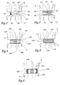
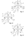
- FIG. 1 represents two vertebrae respectively upper 2 and lower 2 'which are connected via a stabilizing device according to the invention.
- Each vertebra comprises a vertebral body 4, 4 'extended by a pedicle 6, 6', an upper articular 8, 8 'and a lower articular 10, 10'.
- 12 is the intervertebral space, 14 and 14 'articular facets opposite and 16 and 16' joint capsules.
- the two vertebrae 2, 2 ' are interconnected by means of a stabilization device, comprising an intersomatic implant 18, housed in the intervertebral space 12, and a damping member, designated as a whole by the reference 20, both ends of which are attached to the corresponding vertebrae via pedicle screws 22, 22 '.
- a stabilization device comprising an intersomatic implant 18, housed in the intervertebral space 12, and a damping member, designated as a whole by the reference 20, both ends of which are attached to the corresponding vertebrae via pedicle screws 22, 22 '.
- the damping device is for example in accordance with the teaching of FR-A-2 676 911, or even that of FR-A-2 751 864. It may also comprise a ligament, in accordance for example with the teaching of FR-A-2 694 182.
- the implant 18 is shown more precisely in FIG. 2. On the latter, as in the following figures, the right side corresponds to the posterior part of the intervertebral space 12, the left side corresponding to the anterior part.
- the implant 18 comprises respectively upper 24 and lower 26 elements, in contact with the vertebral bodies 4, 4 ', by contact surfaces 24', 26 'respectively, which are planar. Alternatively, these contact surfaces may be of different shapes, including convex.
- the elements 24, 26 comprise respective clevises 24 '', 26 '', which are articulated by means of an axle 28 extending transversely.
- This axis 28, which is disposed on the posterior side of the intervertebral space 12, confers a degree of freedom between the surfaces 24 'and 26', and therefore between the vertebral bodies 4, 4 '.
- This unique degree of freedom is a rotation about the transverse axis, or sagittal, or an extension which corresponds to a flexion of the patient towards the front of it to the rear.
- a spring 30, working in compression, is fixed to the elements 24, 26, on the anterior side of the intervertebral space 12.
- This spring can be replaced by a resilient block made for example of elastomer, in particular rubber.
- FIG. 3 illustrates a second embodiment of the intervertebral implant, designated 68.
- the latter comprises two elements 74 and 76, respectively, which come into contact with the vertebral bodies 4, 4 'via surfaces. flat contacts 74 ', 76'.
- One of these elements in this case the upper element, is provided with a spherical housing 74 '' forming a cupule, disposed towards the rear part of the space intervertebral 12.
- This housing 74 "cooperates with a spherical projection 76" of the other element, namely the lower element 76.
- this implant 68 with one or more springs, similar to that 30, or a resilient block, extending between the upper and lower elements, for example on the anterior side of the intervertebral space.
- FIG. 4 illustrates a third embodiment of the intervertebral implant, which is designated as a whole by reference 118.
- This implant comprises two upper members 124 and lower 126, forming trays. Each of these plates, which bears against a respective vertebral body via a flat surface 124 ', 126', is provided with a spherical recess 124 '', 126 ''.
- a ball 128 which has a radius of curvature substantially less than that of the recesses 124 ", 126", is interposed between the plates 124, 126.
- This ball 128 is free to move in the vicinity of the adjacent surface of the plates 124, 126, which gives three degrees of freedom in rotation, to the two vertebral bodies 4, 4 'around a moving point, as well as two degrees of freedom in translation authorized by the sliding of the plateaux on this ball.
- the latter can be replaced by a non-spherical member, for example oval or cylindrical, bearing against the trays 124, 126 via a contact surface whose radius of curvature is less than that of the recesses 124 ", 126 "above, to allow mutual movement of this body relative to the plateau.
- FIG. 5 represents a fourth variant embodiment of the intervertebral implant, designated as a whole by the reference 168.
- This latter comprises a coating formed by two rigid plates 74, 176, between which is interleaved an elastic core 178.
- the trays 174, 176 partially overlap the core 178, in that they are arranged on the edges of this soul adjacent to the vertebral bodies.
- the plates are for example made of titanium while the core, which is for example glued to the plate, is made for example of silicone or elastomer, especially rubber.
- the trays 174, 176 come into contact with the vertebral bodies 4, 4 'via planar surfaces 174', 176 '.
- This implant is inserted into the intervertebral space by impaction, like the implants 18, 68 and 118. It is also conceivable that the distance separating the contact surfaces 174 ', 176', which corresponds to the vertical dimension of the implant placed , increases towards its anterior part, in the anatomical vertical position of the rest of the patient.
- FIG. 6 illustrates a fifth embodiment of the intervertebral implant, designated as a whole by the reference 218.
- This latter comprises a rigid ball 228 surrounded by a peripheral ring 226, of principal axis parallel to the main axis of the vertebral column, this ring being made of an elastic material such as rubber.
- the lateral ends of the ring are integral with plates 224 which come into contact with the respective vertebral bodies 4, 4 '.
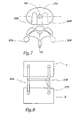
- the implants 18, 68, 118, 168, 218 described above are total disc prostheses. It is also possible to use an implant 268, shown in Figure 7, which is a partial disc prosthesis.
- the latter 268, which is inserted into the disk 270, is arranged offset from the main axis A of the vertebral chain which, when the patient is in a standing position, is a vertical axis passing through the median plane. P extending from behind to the patient.
- This prosthesis can be inserted by screwing or impacting into the intervertebral space.
- This partial prosthesis 268 is associated with a damping member 20A, which is arranged, offset, on the same side of the axis A as the partial prosthesis 268.
- Partial prosthesis 268 can be associated with additional prosthesis 268 ', located on the other side of the axis A.
- This partial prosthesis 268' which is shown in phantom, may be similar to the partial prosthesis 268, it being understood that it is possible to confer on both partial dentures 268, 268 'of different heights, so as to compensate for a possible collapse of the disc occurring asymmetrically, in the back view.
- the partial prosthesis 268 ' is associated with an additional damping member 20B, shown in phantom, which is provided on the same side of the axis A as the partial prosthesis 268'.
- FIG. 8 represents the two damping members 20A, 20B disposed on either side of the articular members 8, 10.
- These damping members have a metal part and are for example in accordance with the teaching of FR-A-2. 751 864. They are advantageously connected to each other by means of a transverse rod 272, extending substantially horizontally.
- the connection between each member 20, 20A and the rod 272 is rigid, and for example involves welding. It is advantageously performed at the middle portion of these damping members.
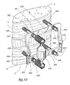
- FIGS 9 to 11 illustrate a further variant of the invention, in which there are provided two upper pedicle screws 322, 324, disposed on either side of the main axis of the spine, and two lower pedicle screws 322 ', 324'.
- the stabilizing device comprises an implant 318, for example similar to that 168, and an extra-discal member 320, which is similar to that 20.
- This stabilizing device also comprises an upper stop element 326, comprising a horizontal branch 328 and two vertical branches 330.
- This branch 328 is hollowed out with two circular openings for the passage of the upper pedicle screw rod 322, 324.
- the walls each opening is extended by an axial sleeve 329, covering a portion of the screw.
- This sleeve which may be integral with the branch 328, receives a stop screw 331 adapted to selectively immobilize the abutment element relative to the pedicle screw, according to a translation parallel to the main axis of the latter.
- This device also comprises a lower abutment element 334, comprising a horizontal branch 336 extended at both ends by rods 337 provided with spheres 338.
- This lower element is hollowed out with two openings for the passage of the rod of the two screws.
- lower pedicles 322 ', 324' are provided with an axial sheath 329 ', provided with a screw 331'.
- At least one of the openings may be an oblong slot. This thus makes it possible to adapt the dimensions of the abutment elements to different spacings of the pedicle screws.
- the horizontal branches 328 and 336 may have variable lengths, for example being telescopic.
- Each vertical branch 330 is folded so that its end has a planar surface 326 'extending obliquely. This means that this end is neither parallel to the medial transverse axis A ', extending from the right to the left of the patient, nor parallel to the median sagittal axis A ", extending from behind to The main axis D of this plane surface 326 'is parallel to a line D passing through the intersection of these two axes A' and A ", in particular a bisector.
- Each surface 326 ' cooperates with a corresponding sphere 338, according to a substantially punctual contact.
- two rotations about the axes A 'and A "are allowed between the upper and lower abutment elements and, in doing so, between the two vertebrae 2 and 2'.
- rotation around the vertical axis A is prohibited between these two vertebrae.
- a mutual translation of the two vertebrae 2, 2 'along the sagittal axis A is allowed in a single direction, so that the superior vertebra can not move forward with respect to the vertebra. lower, but on the other hand is free to move backwards by compared to this lower vertebra.
- any mutual translation of the two vertebrae 2, 2 ' is prohibited, in both directions, along the transverse axis A'.
- a mutual translation between these two vertebrae is allowed, in both directions, along the vertical axis A.
- the upper abutment element can be provided with at least one sphere 338 ', cooperating with a vertical branch, terminated by an oblique planar surface 336', extending from the horizontal branch 336 of the lower element ( Figure 12). It can be used by the cooperation of two adjacent spherical bearing surfaces 342, 342 ', each of which belongs to a respective abutment element (FIG. 13).
- At least one of the vertical branches 330 may, at least partially, be made of an elastic material whose elasticity allows permanent contact between each branch 330 and a corresponding sphere 338. It is also conceivable to realize at least one vertical branch in two parts, having a certain mutual displacement in rotation, around the main axis of the branch. This possibility of deflection may be temporary, for the establishment of the two abutment elements, or permanent to ensure at each instant an angular adjustment between the branch and the sphere.
- each upper or lower element is mounted on two pedicle screws at a time, this makes it possible to avoid any separation of these screws with respect to the vertebral bodies, once they have been put in place.
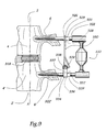
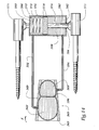
- FIG 14 illustrates a further variant embodiment of the invention.
- the device described therein comprises an implant 368, intended to be inserted at least partially into the intervertebral space.
- This implant includes two chambers respectively before 368 'and rear 368 '', surrounded by two shells 369.
- Each of these which has a cross section substantially in a circular arc, is made of a rigid material, such as titanium.
- These shells 369 which are intended to come into contact with the vertebral bodies 4, 4 ', are subject to the chambers, for example by gluing.
- a damping fluid comprises at least one liquid, such as water or oil. It may also contain air, or a hydrophilic body, such as hydrogel.
- the stabilizing device illustrated in this figure 11 also comprises a damping member 370, disposed at the rear of the intervertebral space.
- This member comprises a rigid tank 372 inside which is disposed a piston 374, which comprises a head 376, forming an upper end, whose transverse dimensions are close to those of the tank.
- An O-ring seal 378 is mounted between the walls facing the head and the tank.
- the piston head 376 extends from a vertical rod 380 which passes, in a sealed manner, the bottom wall 382 of the tank 372, with the interposition of an O-ring 384.
- the lower end of the rod 380, opposed to the head 376, is mounted to the ball on the head of the lower screw 371.
- the piston head delimits respectively upper 386 and lower 388 chambers, belonging to the tank 372.
- the upper chamber receives a spring 390, working in compression, which extends vertically between the upper wall of the tank and the facing wall. the head. This spring allows the return of the piston in its lower position, which corresponds to a lordosed posture of the patient, physiologically advantageous.
- the front chamber of the implant 368 is in fluid communication with the upper chamber of the member 370, through a conduit 392, while the rear chamber of the implant is in fluid communication with the chamber. lower 388 via a conduit 394.
- fluid is driven from the front chamber towards the upper chamber, which helps to lower the piston 374 in the tank, opposite of the upper screw 373.
- This rise induces a fluid movement, through the conduit 394, from the lower chamber to the rear chamber. This bending movement is damped by these different fluid flows.
- the implant belonging to the stabilization device of the invention may be partial or total.
- it is a partial implant
- several implants of this type can be arranged between two same vertebrae. This implant can be placed either anteriorly or posteriorly.
- the intervertebral implant in the form of an envelope containing a hydrophilic gel or water, this implant constituting a nucleus prosthesis.
- the intervertebral implant may contain a damping fluid, and be in accordance with one of the embodiments described in the French patent application, filed on December 29, 1999, under the number 99 16662.
- This fluidic intervertebral implant is capable of cooperate with an extra-discal organ of mechanical type, for example similar to that 20.
- extra-discal member may also contain such a damping fluid, and be in accordance with one of the embodiments described in the application for French patent mentioned above.
- This extra-discal fluidic member is capable of cooperating with a mechanical intervertebral implant, such as for example that 18.
- the invention makes it possible to achieve the objectives mentioned above.
- the device of the invention makes it possible to restore the posterior stability, which had been substantially reduced because of the surgery.
- the intervertebral implant can restore the height of the disc and recall the natural intervertebral movement, given that it gives at least one degree of freedom to the vertebral bodies facing. Moreover, the extra-discarding damping member guarantees an additional component to this posterior stabilization.
- the stabilization device of the invention thus ensures that the relative movement of the two vertebrae that it connects is sufficiently close to the movement authorized by a natural vertebral disk, so that there is no major dysfunction at the level of the entire body. vertebral chain.
- intervertebral implant in the form of at least one partial prosthesis is advantageous. Indeed, such prostheses, because of their size, can be introduced from the rear of the patient, so that it can be used a single operation, during which these prostheses are implanted at the same time as the damping device.
- Providing a single prosthesis, combined with a single extra-disc shock absorber, both offset on the same side of the main axis of the vertebral chain, can overcome asymmetrical collapse of the intervertebral space, seen from behind.
- Such asymmetrical collapses can also be overcome by using two prostheses of different heights, arranged on either side of the main axis of the vertebral chain.
Description
- La présente invention concerne un dispositif de stabilisation intervertébral.
- De manière habituelle, un tel dispositif est destiné à remplacer tout ou partie d'un disque intervertébral, lorsque ce dernier a été détruit par la chirurgie ou la maladie.
- EP-A-282 161 montre un élément de remplacement du disque intervertébral endommagé.
- FR-A-2 676 911 montre un amortisseur relié à deux implants vertébral.>
- L'invention se propose de réaliser un dispositif de stabilisation qui, tout en assurant une liberté de mouvement satisfaisante entre les vertèbres qui lui sont adjacentes, induise seulement de faibles sollicitations mécaniques au niveau de l'ensemble de la chaîne vertébrale.
- A cet effet, elle a pour objet un dispositif de stabilisation intervertébral destiné à relier deux vertèbres voisines, caractérisé en ce qu'il comprend un implant destiné à être inséré au moins partiellement entre les corps vertébraux des deux vertèbres voisines, ledit implant étant apte à conférer auxdits deux corps vertébraux voisins au moins un degré de liberté mutuel, ledit dispositif comprenant également au moins un organe extra-discal, disposé à l'arrière de l'espace intervertébral, propre à amortir un déplacement entre lesdites vertèbres, au moins dans le sens de la flexion intervertébrale.
- Dans le cas où les deux vertèbres voisines possèdent un unique degré de liberté, il s'agit d'un degré de liberté en rotation, autour d'un axe transversal du patient, correspondant aux mouvements de flexion et d'extension de ce patient. Le ou chaque organe extra-discal est propre à amortir un déplacement entre ces vertèbres voisines au moins dans le sens de la flexion intervertébrale, dans laquelle le patient se penche vers l'avant. Cette flexion intervertébrale correspond à l'extension de chaque organe extra-discal, c'est-à-dire à son allongement selon sa direction principale, qui est sensiblement la direction principale de la chaîne vertébrale, soit la verticale lorsque le patient est debout.
- L'invention va être décrite ci-dessous, en référence aux dessins annexés, donnés uniquement à titre d'exemples non limitatifs et dans lesquels :
- la figure 1 est une vue schématique de côté, illustrant deux vertèbres voisines entre lesquelles est placé un dispositif de stabilisation conforme à l'invention ;
- la figure 2 est une vue de côté, à plus grande échelle, illustrant un implant appartenant au dispositif de stabilisation de la figure 1 ;
- les figures 3 à 6 sont des vues analogues à la figure 2, illustrant des variantes de réalisation de l'implant appartenant au dispositif de stabilisation de la figure 1 ;
- la figure 7 est une vue de dessus, illustrant une variante supplémentaire de l'invention ; et
- la figure 8 est une vue de derrière, illustrant les deux organes d'amortissement appartenant au dispositif de stabilisation de la figure 7 ;
- la figure 9 est une vue schématique de côté, analogue à la figure 1, illustrant une variante supplémentaire de réalisation de l'invention ;
- la figure 10 est une vue en perspective, illustrant le dispositif de la figure 9 ;
- les figures 11 à 13 sont des vues de dessus, illustrant le dispositif de la figure 9, puis deux variantes de réalisations ; et
- la figure 14 est une vue de côté illustrant une dernière variante de réalisation de l'invention.
- La figure 1 représente deux vertèbres respectivement supérieure 2 et inférieure 2' qui sont reliées par l'intermédiaire d'un dispositif de stabilisation conforme à l'invention. Chaque vertèbre comprend un corps vertébral 4, 4' prolongé par un pédicule 6, 6', une articulaire supérieure 8, 8' et une articulaire inférieure 10, 10'. On désigne par 12 l'espace intervertébral, par 14 et 14' les facettes articulaires en regard et par 16 et 16' les capsules articulaires.
- Les deux vertèbres 2, 2' sont reliées mutuellement par l'intermédiaire d'un dispositif de stabilisation, comprenant un implant intersomatique 18, logé dans l'espace intervertébral 12, ainsi qu'un organe d'amortissement, désigné dans son ensemble par la référence 20, dont les deux extrémités sont fixées sur les vertèbres correspondantes par l'intermédiaire de vis pédiculaires 22, 22'.
- L'organe d'amortissement est par exemple conforme à l'enseignement de FR-A-2 676 911, ou bien encore à celui de FR-A-2 751 864. Il peut également comprendre un ligament, conformément par exemple à l'enseignement de FR-A-2 694 182.
- L'implant 18 est représenté de façon plus précise sur la figure 2. Sur cette dernière, comme sur les figures suivantes, le côté droit correspond à la partie postérieure de l'espace intervertébral 12, le côté gauche correspondant à la partie antérieure.
- L'implant 18 comprend des éléments respectivement supérieur 24 et inférieur 26, entrant en contact avec les corps vertébraux 4, 4', par des surfaces de contact 24', 26' respectives, qui sont planes. A titre de variante, ces surfaces de contact peuvent être de formes différentes, notamment convexes.
- Les éléments 24, 26 comportent des chapes respectives 24'', 26'', qui sont articulées au moyen d'un axe 28 s'étendant transversalement. Cet axe 28, qui est disposé du côté postérieur de l'espace intervertébral 12, confère un degré de liberté entre les surfaces 24' et 26', et donc entre les corps vertébraux 4, 4'. Ce degré de liberté unique est une rotation autour de l'axe 28 transversal, ou sagittal, ou à une extension ce qui correspond ainsi à une flexion du patient vers l'avant de celui-ci vers l'arrière.
- Un ressort 30, travaillant en compression, est fixé aux éléments 24, 26, du côté antérieur de l'espace intervertébral 12. Ce ressort peut être remplacé par un bloc résilient, réalisé par exemple en élastomère, notamment en caoutchouc.
- La figure 3 illustre un second mode de réalisation de l'implant intervertébral, désigné par la référence 68. Ce dernier comprend deux éléments respectivement supérieur 74 et inférieur 76, entrant en contact avec les corps vertébraux 4, 4' par l'intermédiaire de surfaces de contact planes 74', 76'.
- L'un de ces éléments, en l'occurrence l'élément supérieur, est pourvu d'un logement sphérique 74'', formant cupule, disposé vers la partie postérieure de l'espace intervertébral 12. Ce logement 74'' coopère avec une saillie sphérique 76" de l'autre élément, à savoir l'élément inférieur 76.
- Etant donné que les rayons du logement 74'' et de la saillie 76'' sont sensiblement identiques, leur coopération assure trois degrés de liberté en rotation, autour du centre fixe 78 de la saillie sphérique 76", des surfaces de contact 74', 76' et donc des corps vertébraux 4, 4'.
- Il est possible de munir cet implant 68 d'un ou plusieurs ressorts, analogues à celui 30, ou d'un bloc résilient, s'étendant entre les éléments supérieur et inférieur, par exemple du côté antérieur de l'espace intervertébral.
- La figure 4 illustre un troisième mode de réalisation de l'implant intervertébral, qui est désigné dans son ensemble par la référence 118. Cet implant comprend deux éléments supérieur 124 et inférieur 126, formant plateaux. Chacun de ces plateaux, qui prend appui contre un corps vertébral respectif par l'intermédiaire d'une surface plane 124', 126', est pourvu d'un renfoncement sphérique 124'', 126''. Une bille 128 qui possède un rayon de courbure sensiblement inférieur à celui des renfoncements 124", 126", est intercalée entre les plateaux 124, 126.
- Cette bille 128 est libre de se déplacer au voisinage de la surface adjacente des plateaux 124, 126, ce qui confère trois degrés de liberté en rotation, aux deux corps vertébraux 4, 4' autour d'un point mobile, ainsi que deux degrés de liberté en translation autorisés par les glissements des plateaux sur cette bille. Cette dernière peut être remplacée par un organe non sphérique, par exemple ovale ou cylindrique, prenant appui contre les plateaux 124, 126 par l'intermédiaire d'une surface de contact dont le rayon de courbure est inférieur à celui des renfoncements 124", 126" précités, afin de permettre un déplacement mutuel de cet organe par rapport au plateau.
- La figure 5 représente une quatrième variante de réalisation de l'implant intervertébral, désigné dans son ensemble par la référence 168. Ce dernier comprend un enrobage, formé par deux plateaux rigides 74, 176, entre lesquels est intercalée une âme élastique 178. Les plateaux 174, 176 recouvrent partiellement l'âme 178, en ce sens qu'ils sont disposés sur les bords de cette âme adjacents aux corps vertébraux. Les plateaux sont par exemple réalisés en titane alors que l'âme, qui est par exemple collée au plateau, est réalisée par exemple en silicone ou en élastomère, notamment en caoutchouc.
- Les plateaux 174, 176 entrent en contact avec les corps vertébraux 4, 4' par l'intermédiaire de surfaces planes 174', 176'. Cet implant est inséré dans l'espace intervertébral par impaction, comme les implants 18, 68 et 118. Il est également envisageable que la distance séparant les surfaces de contact 174', 176', qui correspond à la dimension verticale de l'implant posé, augmente vers sa partie antérieure, dans la position anatomique verticale du repos du patient.
- La figure 6 illustre un cinquième mode de réalisation de l'implant intervertébral, désigné dans son ensemble par la référence 218. Ce dernier comprend une bille rigide 228 entourée par un anneau périphérique 226, d'axe principal parallèle à l'axe principal de la colonne vertébrale, cet anneau étant réalisé en un matériau élastique tel que du caoutchouc. Les extrémités latérales de l'anneau sont solidaires de plaques 224 qui entrent en contact avec les corps vertébraux respectifs 4, 4'.
- Les implants 18, 68, 118, 168, 218 décrits ci-dessus sont des prothèses totales de disque. Il est également possible de faire appel à un implant 268, illustré sur la figure 7, qui est une prothèse partielle de disque. Cette dernière 268, qui est insérée dans le disque 270, est disposée de façon décalée, par rapport à l'axe principal A de la chaîne vertébrale qui, lorsque le patient se trouve en position debout, est un axe vertical passant par le plan médian P s'étendant d'arrière en avant du patient. Cette prothèse peut être insérée par vissage ou impactage dans l'espace intervertébral.
- Cette prothèse partielle 268 est associée à un organe d'amortissement 20A, qui est disposée, de façon décalée, du même côté de l'axe A que la prothèse partielle 268.
- On peut associer à la prothèse partielle 268, une prothèse supplémentaire 268', située de l'autre côté de l'axe A. Cette prothèse partielle 268', qui est représentée en traits mixtes, peut être analogue à la prothèse partielle 268 étant entendu qu'il est possible de conférer à ces deux prothèses partielles 268, 268' des hauteurs différentes, de manière à compenser un éventuel effondrement du disque se produisant de façon asymétrique, en vue de derrière. La prothèse partielle 268' est associée à un organe d'amortissement supplémentaire 20B, représenté en traits mixtes, qui est prévu du même côté de l'axe A que la prothèse partielle 268'.
- La figure 8 représente les deux organes d'amortissement 20A, 20B disposés de part et d'autre des articulaires 8, 10. Ces organes d'amortissement présentent une partie métallique et sont par exemple conformes à l'enseignement de FR-A-2 751 864. Ils sont avantageusement reliés l'un à l'autre au moyen d'une tige transversale 272, s'étendant sensiblement horizontalement. La liaison entre chaque organe 20, 20A et la tige 272 est rigide, et fait par exemple intervenir une soudure. Elle est avantageusement réalisée au niveau de la partie médiane de ces organes d'amortissement.
- Les figures 9 à 11 illustrent une variante supplémentaire de l'invention, dans laquelle il est prévu deux vis pédiculaires supérieures 322, 324, disposées de part et d'autre de l'axe principal de la colonne vertébrale, ainsi que deux vis pédiculaires inférieures 322', 324'. Le dispositif de stabilisation comprend un implant 318, par exemple analogue à celui 168, ainsi qu'un organe extra-discal 320, qui est analogue à celui 20.
- Ce dispositif de stabilisation comprend également un élément de butée supérieur 326, comportant une branche horizontale 328 ainsi que deux branches verticales 330. Cette branche 328 est creusée de deux ouvertures circulaires destinées au passage de la tige des vis pédiculaires supérieures 322, 324. Les parois de chaque ouverture sont prolongées par un fourreau axial 329, recouvrant une partie de la vis. Ce fourreau, qui peut être venu de matière avec la branche 328, reçoit une vis d'arrêt 331 apte à immobiliser de façon sélective l'élément de butée par rapport à la vis pédiculaire, selon une translation parallèle à l'axe principal de cette dernière.
- Ce dispositif comprend également un élément de butée inférieur 334, comportant une branche horizontale 336 prolongée, à ses deux extrémités, par des tiges 337 pourvues de sphères 338. Cet élément inférieur est creusé de deux ouvertures, destinées au passage de la tige des deux vis pédiculaires inférieures 322', 324'. De façon analogue à ce qui a été décrit ci-dessus pour l'élément supérieur, chaque ouverture est pourvue d'un fourreau axial 329', muni d'une vis 331'.
- Par ailleurs, en variante, au moins une des ouvertures peut être une lumière oblongue. Ceci permet ainsi d'adapter les dimensions des éléments de butée à différents espacements des vis pédiculaires. Les branches horizontales 328 et 336 peuvent présenter des longueurs variables, en étant par exemple télescopiques.
- Chaque branche verticale 330 est repliée, de sorte que son extrémité possède une surface plane 326' s'étendant de façon oblique. Ceci signifie que cette extrémité n'est ni parallèle à l'axe transversal médian A', s'étendant de la droite vers la gauche du patient, ni parallèle à l'axe sagittal médian A", s'étendant d'arrière en avant du patient (figure 11). L'axe principal D de cette surface plane 326' est parallèle à une droite D' passant par l'intersection de ces deux axes A' et A", notamment une bissectrice.
- Chaque surface 326' coopère avec une sphère 338 correspondante, selon un contact sensiblement ponctuel. De la sorte, deux rotations autour des axes A' et A'' sont autorisées entre les éléments de butée supérieur et inférieur et, ce faisant, entre les deux vertèbres 2 et 2'. En revanche, la rotation autour de l'axe vertical A est interdite entre ces deux vertèbres.
- Par ailleurs, une mise en translation mutuelle des deux vertèbres 2, 2', selon l'axe sagittal A", est autorisée dans un unique sens. Ainsi, la vertèbre supérieure ne peut se déplacer vers l'avant, par rapport à la vertèbre inférieure, mais en revanche est libre de se déplacer vers l'arrière par rapport à cette vertèbre inférieure.
- En outre, toute translation mutuelle des deux vertèbres 2, 2' est interdite, dans les deux sens, selon l'axe transversal A'. Enfin, une translation mutuelle entre ces deux vertèbres est autorisée, dans les deux sens, selon l'axe vertical A.
- D'autres agencements peuvent être envisagés. Ainsi, l'élément de butée supérieur peut être muni d'au moins une sphère 338', coopérant avec une branche verticale, terminée par une surface plane oblique 336', s'étendant à partir de la branche horizontale 336 de l'élément inférieur (figure 12). Il peut être fait appel à la coopération de deux surfaces d'appui sphériques adjacentes 342, 342', dont chacune appartient à un élément de butée respectif (figure 13).
- A titre de variante supplémentaire, au moins une des branches verticales 330 peut, au moins partiellement, être réalisée en un matériau élastique, dont l'élasticité autorise un contact permanent entre chaque branche 330 et une sphère correspondante 338. Il est également envisageable de réaliser au moins une branche verticale en deux parties, possédant un certain débattement mutuel en rotation, autour de l'axe principal de la branche. Cette possibilité de débattement peut être provisoire, pour la mise en place des deux éléments de butée, ou permanente afin d'assurer à chaque instant une adaptation angulaire entre la branche et la sphère.
- Il est possible de prévoir une unique branche verticale 330, coopérant avec une unique sphère 338, notamment dans le cas où une partie de l'articulation postérieure naturelle n'a pas été détruite.
- Etant donné que chaque élément supérieur ou inférieur est monté sur deux vis pédiculaires à la fois, ceci permet d'éviter toute désolidarisation de ces vis par rapport aux corps vertébraux, une fois celles-ci mises en place.
- La figure 14 illustre une variante supplémentaire de réalisation de l'invention. Le dispositif qui y est décrit comprend un implant 368, destiné à être inséré au moins partiellement dans l'espace intervertébral. Cet implant comprend deux chambres respectivement avant 368' et arrière 368'', entourées par deux coquilles 369. Chacune de ces dernières, qui présente une section transversale sensiblement en arc de cercle, est réalisée en un matériau rigide, tel que du titane. Ces coquilles 369, qui sont destinées à entrer en contact avec les corps vertébraux 4, 4', sont assujetties aux chambres, par exemple par collage.
- Ces deux chambres 368, 368', qui sont séparées par une membrane 396, éventuellement poreuse, sont remplies d'un fluide d'amortissement. Ce dernier comprend au moins un liquide, tel que de l'eau ou de l'huile. Il peut également contenir de l'air, ou encore un corps hydrophile, tel de l'hydrogel.
- Le dispositif de stabilisation illustré sur cette figure 11 comprend également un organe d'amortissement 370, disposé à l'arrière de l'espace intervertébral. Cet organe comprend une cuve rigide 372 à l'intérieur de laquelle est disposé un piston 374, qui comprend une tête 376, formant extrémité supérieure, dont les dimensions transversales sont voisines de celles de la cuve. Un joint torique d'étanchéité 378 est monté entre les parois en regard de la tête et de la cuve.
- La tête 376 du piston s'étend à partir d'une tige 380 verticale qui traverse, de façon étanche, la paroi inférieure 382 de la cuve 372, avec interposition d'un joint torique 384. L'extrémité inférieure de la tige 380, opposée à la tête 376, est montée à rotule sur la tête de la vis inférieure 371.
- La tête du piston délimite des chambres respectivement supérieure 386 et inférieure 388, appartenant à la cuve 372. La chambre supérieure reçoit un ressort 390, travaillant en compression, qui s'étend verticalement entre la paroi supérieure de la cuve et la paroi en regard de la tête. Ce ressort permet le rappel du piston dans sa position basse, qui correspond à une posture lordosée du patient, physiologiquement avantageuse.
- La chambre avant de l'implant 368 est mise en communication fluidique avec la chambre supérieure de l'organe 370, par l'intermédiaire d'un conduit 392, alors que la chambre arrière de l'implant est mise en communication fluidique avec la chambre inférieure 388 par l'intermédiaire d'un conduit supplémentaire 394. De la sorte, lorsque le patient se penche vers l'avant, selon la flèche F, du fluide est chassé de la chambre avant en direction de la chambre supérieure, ce qui contribue à faire descendre le piston 374 dans la cuve, à l'opposé de la vis supérieure 373. Cette remontée induit un déplacement de fluide, par le conduit 394, de la chambre inférieure vers la chambre arrière. Ce mouvement de flexion est donc amorti par ces différents écoulements de fluide.
- L'invention n'est pas limitée aux exemples décrits et représentés.
- L'implant appartenant au dispositif de stabilisation de l'invention peut être partiel ou total. Dans le cas où il s'agit d'un implant partiel, plusieurs implants de ce type peuvent être disposés entre deux mêmes vertèbres. Cet implant peut être mis en place, soit par voie antérieure, soit par voie postérieure.
- Par ailleurs, on peut prévoir d'utiliser une bille unique, analogue à celle 228, qui confère trois degrés de liberté en rotation, ainsi que deux degrés de liberté en translation aux corps vertébraux 4, 4'. Il est également possible de réaliser l'implant intervertébral sous forme d'une enveloppe renfermant un gel hydrophile ou de l'eau, cet implant constituant une prothèse de nucleus.
- Il est également possible de fixer l'implant sur la paroi verticale des corps vertébraux, par exemple par vissage, conformément à l'enseignement de EP-A-0 346 269, cet implant étant alors inséré seulement partiellement entre les deux corps vertébraux.
- L'implant intervertébral peut renfermer un fluide d'amortissement, et être conforme à l'un des modes de réalisation décrits dans la demande de brevet français, déposée le 29 décembre 1999, sous le numéro 99 16662. Cet implant intervertébral fluidique est susceptible de coopérer avec un organe extra-discal de type mécanique, par exemple analogue à celui 20.
- Par ailleurs, l'organe extra-discal peut également renfermer un tel fluide d'amortissement, et être conforme à l'un des modes de réalisation décrits dans la demande de brevet français ci-dessus mentionnée. Cet organe extra-discal fluidique est susceptible de coopérer avec un implant intervertébral mécanique, tel que par exemple celui 18.
- L'invention permet de réaliser les objectifs précédemment mentionnés.
- En cas de pathologie dégénérative du disque intervertébral, s'étendant aux nerfs qui lui sont adjacents, il est nécessaire pour le chirurgien de libérer la racine nerveuse ainsi comprimée. A cet effet, l'opération correspondante induit une destruction au moins partielle de l'articulation intervertébrale postérieure.
- Le dispositif de l'invention permet de restaurer la stabilité postérieure, qui avait été sensiblement diminuée du fait de la chirurgie.
- L'implant intervertébral permet de restaurer la hauteur du disque et de rappeler le mouvement intervertébral naturel, étant donné qu'il confère au moins un degré de liberté aux corps vertébraux en regard. Par ailleurs, l'organe d'amortissement extra-discal garantit une composante supplémentaire à cette stabilisation postérieure.
- Le fait de combiner cet implant intervertébral et cet organe extra-discal permet de réaliser ces deux éléments de manière simple et fiable. Il est ainsi possible de répartir, entre ces deux éléments, les différentes fonctions mécaniques qui sont nécessaires, en vue d'assurer une stabilité intervertébrale satisfaisante. Ceci permet donc de réduire les contraintes mécaniques exercées sur chacun de ces deux éléments, de sorte que ces derniers sont soumis à une usure restreinte. Ceci en allonge donc la durée de vie de façon correspondante.
- Le dispositif de stabilisation de l'invention garantit ainsi que le mouvement relatif des deux vertèbres qu'il relie est suffisamment proche du mouvement autorisé par un disque vertébral naturel, pour que n'apparaisse pas de dysfonctionnement majeur au niveau de l'ensemble de la chaîne vertébrale.
- L'emploi de deux organes d'amortissement extra-discaux, disposés de part et d'autres d'un axe principal de la colonne vertébrale est avantageux. En effet, il assure une composante supplémentaire d'amortissement, lorsque le patient se penche sur les côtés.
- Prévoir des moyens de liaison entre ces deux organes d'amortissement est avantageux, dans la mesure où cela assure une réduction sensible du cisaillement horizontal intervertébral, comme en cas de rupture ou d'absence d'un ou de deux massifs articulaires postérieurs.
- Réaliser l'implant intervertébral sous la forme d'au moins une prothèse partielle est avantageux. En effet, de telles prothèses, du fait de leur dimensions, peuvent être introduites depuis l'arrière du patient, de sorte qu'il peut être fait appel à une unique opération, au cours de laquelle ces prothèses sont implantées en même temps que l'organe d'amortissement.
- Prévoir une unique prothèse, associée à un unique organe d'amortissement extra-discal, tous deux décalés d'un même côté de l'axe principal de la chaîne vertébrale, permet de remédier à des effondrements asymétriques de l'espace intervertébral, vu de derrière. De tels effondrements asymétriques peuvent également être palliés en faisant appel à deux prothèses de hauteurs différentes, disposées de part et d'autre de l'axe principal de la chaîne vertébrale.
Claims (21)
- Dispositif de stabilisation intervertébral destiné à relier deux vertèbres voisines (2, 2'), le dispositif comprenant un implant (18 ; 68 ; 118 ; 168 ; 218 ; 268 ; 318 ; 368) destiné à être inséré au moins partiellement entre les corps vertébraux (4, 4') des deux vertèbres voisines, ledit implant (18 ; 68 ; 118 ; 168 ; 218 ; 268 ; 318 ; 368) étant apte à conférer auxdits deux corps vertébraux voisins (4, 4') au moins un degré de liberté mutuel, ledit dispositif comprenant également au moins un organe extra-discal (20 ; 320 ; 370), apte à être disposé à l'arrière de l'espace intervertébral (12), propre à amortir un déplacement entre lesdites vertèbres (2, 2'), au moins dans le sens de la flexion intervertébrale.
- Dispositif selon la revendication 1, caractérisé en ce que ledit implant (18 ; 68) est apte à conférer aux deux corps vertébraux (4, 4') au moins un degré de liberté en rotation, autour d'un pivot fixe (28 ; 78) dudit implant.
- Dispositif selon la revendication 2, caractérisé en ce qu'il est prévu des moyens supplémentaires d'amortissement (30) au moins dans le sens de la flexion intervertébrale, disposés vers la partie antérieure dudit implant (18 ; 68).
- Dispositif selon la revendication 1, caractérisé en ce que ledit implant (118) est apte à conférer aux deux corps vertébraux (4, 4') au moins un degré de liberté en rotation, autour d'un pivot mobile (128 ; 228) dudit implant.
- Dispositif selon la revendication 1, caractérisé en ce que ledit implant (168) comprend une âme élastique (178), notamment réalisée en un polymère de silicone ou un élastomère, partiellement recouverte par un enrobage (174, 176) réalisé en un matériau rigide.
- Dispositif selon l'une quelconque des revendications précédentes, caractérisé en ce qu'il est prévu deux organes d'amortissement extra-discaux (20A, 20B) disposés de part et d'autre d'un axe principal (A) de la chaîne vertébrale.
- Dispositif selon la revendication 6, caractérisé en ce qu'il est prévu en outre des moyens de solidarisation (272) des organes d'amortissement (20A, 20B) entre eux.
- Dispositif selon l'une des revendications précédentes, caractérisé en ce que ledit implant comprend au moins une prothèse partielle (268, 268') de disque.
- Dispositif selon la revendication 8, caractérisé en ce que ledit implant intervertébral comprend une unique prothèse partielle (268), associée à un unique organe (20A) d'amortissement extra-discal, tous deux étant décalés d'un même côté par rapport à l'axe principal (A) de la chaîne vertébrale.
- Dispositif selon la revendication 9, caractérisé en ce que ledit implant intervertébral comprend deux prothèses partielles (268, 268') disposées de part et d'autre dudit axe principal (A), ainsi que deux organes (20A, 20B) d'amortissement extra-discaux, disposés de part et d'autre dudit axe (A).
- Dispositif selon l'une des revendications précédentes, caractérisé en ce qu'il comprend en outre un élément de butée supérieur (326), solidaire d'une vertèbre supérieure, ainsi qu'un élément de butée inférieur (334), solidaire d'une vertèbre inférieure, ces éléments de butée extra-discaux possédant des surfaces d'appui mutuelles (326', 338 ; 336', 338' ; 342, 342') aptes à autoriser une rotation mutuelle desdites vertèbres supérieure (2) et inférieure (2') autour d'axes transversal (A') et sagittal (A'') du patient, ainsi qu'à empêcher une rotation mutuelle de ces deux vertèbres autour d'un axe vertical (A), ces surfaces d'appui étant en outre aptes à autoriser une translation mutuelle de ces vertèbres dans un unique sens selon l'axe sagittal (A"), à autoriser une translation entre ces deux vertèbres dans les deux sens selon l'axe vertical (A), et à interdire une translation entre ces deux vertèbres dans les deux sens selon l'axe transversal (A').
- Dispositif selon la revendication 11, caractérisé en ce que l'un desdits éléments de butée comprend deux surfaces d'appui planes (326'), disposées de part et d'autre de l'axe vertical (A), ces deux surfaces s'étendant de façon oblique et coopérant avec deux sphères (338) dont est pourvu l'autre desdits éléments.
- Dispositif selon les revendications 11 ou 12, caractérisé en ce que chaque élément de butée (326, 334) est solidaire de deux vis pédiculaires, respectivement supérieures (322, 324) et inférieures (322', 324').
- Dispositif selon la revendication 13, caractérisé en ce qu'il est prévu des moyens (331, 331') permettant de solidariser en translation, de façon sélective, chaque élément de butée avec au moins une vis pédiculaire.
- Dispositif selon l'une quelconque des revendications précédentes, caractérisé en ce que ledit implant (368) comprend au moins une chambre (368', 368'') et en ce que ledit organe extra-discal (370) comprend au moins une chambre (386, 388), lesdites au moins deux chambres renfermant un fluide, et en ce que sont prévus des moyens (392, 394) de mise en communication fluidique de ces chambres.
- Dispositif selon la revendication 15, caractérisé en ce que les moyens de mise en communication comprennent au moins un conduit (392, 394) s'étendant entre ces chambres.
- Dispositif selon la revendication 15, caractérisé en ce qu'un premier conduit assure la communication entre les chambres dans un premier sens, alors qu'un second conduit assure cette communication dans un second sens, opposé au premier, les sections de passage des premier et second conduits étant différentes.
- Dispositif selon l'une des revendications 15 à 17, caractérisé en ce que l'implant (368) et/ou l'organe extra-discal comprend au moins deux chambres (368', 368'') et en ce qu'un élément poreux (396) sépare lesdites chambres.
- Dispositif selon la revendication 18, caractérisé en ce que ledit organe poreux est mobile par rapport à ces chambres.
- Dispositif selon l'une des revendications 15 à 19, caractérisé en ce qu'il est prévu au moins un piston (374), séparant deux chambres adjacentes.
- Dispositif selon l'une des revendications 15 à 20, caractérisé en ce qu'au moins une chambre est pourvue d'une paroi déformable.
Applications Claiming Priority (7)
| Application Number | Priority Date | Filing Date | Title |
|---|---|---|---|
| FR9915160 | 1999-12-01 | ||
| FR9915160A FR2801782B3 (fr) | 1999-12-01 | 1999-12-01 | Dispositif de stabilisation intervertebral |
| FR9916662A FR2803188A1 (fr) | 1999-12-29 | 1999-12-29 | Dispositif et ensemble intervertebraux de stabilisation |
| FR9916662 | 1999-12-29 | ||
| FR0006640 | 2000-05-24 | ||
| FR0006640A FR2809304A1 (fr) | 2000-05-24 | 2000-05-24 | Dispositif de stabilisation intervertebral |
| PCT/FR2000/003368 WO2001039678A1 (fr) | 1999-12-01 | 2000-12-01 | Dispositif de stabilisation intervertebral |
Publications (2)
| Publication Number | Publication Date |
|---|---|
| EP1233711A1 EP1233711A1 (fr) | 2002-08-28 |
| EP1233711B1 true EP1233711B1 (fr) | 2006-08-23 |
Family
ID=27248663
Family Applications (1)
| Application Number | Title | Priority Date | Filing Date |
|---|---|---|---|
| EP00985390A Expired - Lifetime EP1233711B1 (fr) | 1999-12-01 | 2000-12-01 | Dispositif de stabilisation intervertebral |
Country Status (9)
| Country | Link |
|---|---|
| US (2) | US7291150B2 (fr) |
| EP (1) | EP1233711B1 (fr) |
| JP (1) | JP4294901B2 (fr) |
| AT (1) | ATE336952T1 (fr) |
| AU (1) | AU778410B2 (fr) |
| CA (1) | CA2392868C (fr) |
| DE (1) | DE60030313T2 (fr) |
| ES (1) | ES2270888T3 (fr) |
| WO (1) | WO2001039678A1 (fr) |
Families Citing this family (351)
| Publication number | Priority date | Publication date | Assignee | Title |
|---|---|---|---|---|
| US6273912B1 (en) * | 1996-02-28 | 2001-08-14 | Impra, Inc. | Flanged graft for end-to-side anastomosis |
| US7621950B1 (en) | 1999-01-27 | 2009-11-24 | Kyphon Sarl | Expandable intervertebral spacer |
| US6569155B1 (en) * | 1999-03-15 | 2003-05-27 | Altus Medical, Inc. | Radiation delivery module and dermal tissue treatment method |
| US6974478B2 (en) * | 1999-10-22 | 2005-12-13 | Archus Orthopedics, Inc. | Prostheses, systems and methods for replacement of natural facet joints with artificial facet joint surfaces |
| US8187303B2 (en) * | 2004-04-22 | 2012-05-29 | Gmedelaware 2 Llc | Anti-rotation fixation element for spinal prostheses |
| US7674293B2 (en) * | 2004-04-22 | 2010-03-09 | Facet Solutions, Inc. | Crossbar spinal prosthesis having a modular design and related implantation methods |
| US20050027361A1 (en) * | 1999-10-22 | 2005-02-03 | Reiley Mark A. | Facet arthroplasty devices and methods |
| US6811567B2 (en) * | 1999-10-22 | 2004-11-02 | Archus Orthopedics Inc. | Facet arthroplasty devices and methods |
| EP1223872B2 (fr) * | 1999-10-22 | 2007-09-26 | Archus Orthopedics Inc. | Dispositif d'arthroplastie facettaire |
| US7691145B2 (en) * | 1999-10-22 | 2010-04-06 | Facet Solutions, Inc. | Prostheses, systems and methods for replacement of natural facet joints with artificial facet joint surfaces |
| AU778410B2 (en) | 1999-12-01 | 2004-12-02 | Henry Graf | Intervertebral stabilising device |
| US7938836B2 (en) * | 2003-10-23 | 2011-05-10 | Trans1, Inc. | Driver assembly for simultaneous axial delivery of spinal implants |
| US7601171B2 (en) * | 2003-10-23 | 2009-10-13 | Trans1 Inc. | Spinal motion preservation assemblies |
| US7776068B2 (en) * | 2003-10-23 | 2010-08-17 | Trans1 Inc. | Spinal motion preservation assemblies |
| US7833250B2 (en) | 2004-11-10 | 2010-11-16 | Jackson Roger P | Polyaxial bone screw with helically wound capture connection |
| US20080177310A1 (en) * | 2000-10-20 | 2008-07-24 | Archus Orthopedics, Inc. | Facet arthroplasty devices and methods |
| US6579319B2 (en) * | 2000-11-29 | 2003-06-17 | Medicinelodge, Inc. | Facet joint replacement |
| US20050080486A1 (en) | 2000-11-29 | 2005-04-14 | Fallin T. Wade | Facet joint replacement |
| FR2817461B1 (fr) | 2000-12-01 | 2003-08-15 | Henry Graf | Dispositif de stabilisation intervertebral |
| US7090698B2 (en) | 2001-03-02 | 2006-08-15 | Facet Solutions | Method and apparatus for spine joint replacement |
| GB0107708D0 (en) | 2001-03-28 | 2001-05-16 | Imp College Innovations Ltd | Bone fixated,articulated joint load control device |
| US20050261682A1 (en) * | 2002-04-13 | 2005-11-24 | Ferree Bret A | Vertebral shock absorbers |
| EP1585427B1 (fr) * | 2002-05-08 | 2012-04-11 | Stephen Ritland | Dispositif de fixation dynamique |
| US7001433B2 (en) | 2002-05-23 | 2006-02-21 | Pioneer Laboratories, Inc. | Artificial intervertebral disc device |
| US8388684B2 (en) * | 2002-05-23 | 2013-03-05 | Pioneer Signal Technology, Inc. | Artificial disc device |
| DE10236691B4 (de) * | 2002-08-09 | 2005-12-01 | Biedermann Motech Gmbh | Dynamische Stabilisierungseinrichtung für Knochen, insbesondere für Wirbel |
| JP4456481B2 (ja) * | 2002-08-15 | 2010-04-28 | ガーバー,デイヴィッド | 制御された人工椎間板インプラント |
| CN100577123C (zh) * | 2002-08-15 | 2010-01-06 | 新特斯有限责任公司 | 椎间盘植入体 |
| CA2495404C (fr) * | 2002-08-15 | 2011-05-03 | Justin K. Coppes | Disque intervertebral artificiel |
| AU2003265597A1 (en) * | 2002-08-23 | 2004-03-11 | Paul C. Mcafee | Metal-backed uhmpe rod sleeve system preserving spinal motion |
| US8876868B2 (en) | 2002-09-06 | 2014-11-04 | Roger P. Jackson | Helical guide and advancement flange with radially loaded lip |
| FR2845587B1 (fr) * | 2002-10-14 | 2005-01-21 | Scient X | Dispositif dynamique de liaison intervertebrale a debattement controle multidirectionnel |
| US7776042B2 (en) | 2002-12-03 | 2010-08-17 | Trans1 Inc. | Methods and apparatus for provision of therapy to adjacent motion segments |
| US6969405B2 (en) * | 2003-04-23 | 2005-11-29 | Loubert Suddaby | Inflatable intervertebral disc replacement prosthesis |
| US7713287B2 (en) * | 2003-05-02 | 2010-05-11 | Applied Spine Technologies, Inc. | Dynamic spine stabilizer |
| US7635379B2 (en) | 2003-05-02 | 2009-12-22 | Applied Spine Technologies, Inc. | Pedicle screw assembly with bearing surfaces |
| US7615068B2 (en) | 2003-05-02 | 2009-11-10 | Applied Spine Technologies, Inc. | Mounting mechanisms for pedicle screws and related assemblies |
| US8652175B2 (en) * | 2003-05-02 | 2014-02-18 | Rachiotek, Llc | Surgical implant devices and systems including a sheath member |
| US7029475B2 (en) * | 2003-05-02 | 2006-04-18 | Yale University | Spinal stabilization method |
| US7291173B2 (en) | 2003-05-06 | 2007-11-06 | Aesculap Ii, Inc. | Artificial intervertebral disc |
| US7105024B2 (en) * | 2003-05-06 | 2006-09-12 | Aesculap Ii, Inc. | Artificial intervertebral disc |
| EP1514527A3 (fr) * | 2003-05-06 | 2005-10-26 | Spinal Innovations, LLC | Disque intervertébral artificiel |
| US20050143824A1 (en) * | 2003-05-06 | 2005-06-30 | Marc Richelsoph | Artificial intervertebral disc |
| US20040230304A1 (en) * | 2003-05-14 | 2004-11-18 | Archus Orthopedics Inc. | Prostheses, tools and methods for replacement of natural facet joints with artifical facet joint surfaces |
| US7608104B2 (en) * | 2003-05-14 | 2009-10-27 | Archus Orthopedics, Inc. | Prostheses, tools and methods for replacement of natural facet joints with artifical facet joint surfaces |
| DE20308171U1 (de) * | 2003-05-21 | 2003-07-31 | Aesculap Ag & Co Kg | Wirbelkörperersatzimplantat |
| US7377923B2 (en) | 2003-05-22 | 2008-05-27 | Alphatec Spine, Inc. | Variable angle spinal screw assembly |
| US8366753B2 (en) | 2003-06-18 | 2013-02-05 | Jackson Roger P | Polyaxial bone screw assembly with fixed retaining structure |
| US7766915B2 (en) | 2004-02-27 | 2010-08-03 | Jackson Roger P | Dynamic fixation assemblies with inner core and outer coil-like member |
| US7967850B2 (en) | 2003-06-18 | 2011-06-28 | Jackson Roger P | Polyaxial bone anchor with helical capture connection, insert and dual locking assembly |
| US8926670B2 (en) | 2003-06-18 | 2015-01-06 | Roger P. Jackson | Polyaxial bone screw assembly |
| US7776067B2 (en) | 2005-05-27 | 2010-08-17 | Jackson Roger P | Polyaxial bone screw with shank articulation pressure insert and method |
| US7074238B2 (en) | 2003-07-08 | 2006-07-11 | Archus Orthopedics, Inc. | Prostheses, tools and methods for replacement of natural facet joints with artificial facet joint surfaces |
| US7153325B2 (en) * | 2003-08-01 | 2006-12-26 | Ultra-Kinetics, Inc. | Prosthetic intervertebral disc and methods for using the same |
| US8052723B2 (en) | 2003-08-05 | 2011-11-08 | Flexuspine Inc. | Dynamic posterior stabilization systems and methods of use |
| US7753958B2 (en) | 2003-08-05 | 2010-07-13 | Gordon Charles R | Expandable intervertebral implant |
| US7909869B2 (en) | 2003-08-05 | 2011-03-22 | Flexuspine, Inc. | Artificial spinal unit assemblies |
| US7255714B2 (en) | 2003-09-30 | 2007-08-14 | Michel H. Malek | Vertically adjustable intervertebral disc prosthesis |
| DE10347175B4 (de) * | 2003-10-08 | 2005-10-20 | Aesculap Ag & Co Kg | Zwischenwirbelimplantat |
| DE10347172B4 (de) * | 2003-10-08 | 2005-09-29 | Aesculap Ag & Co. Kg | Zwischenwirbelimplantat |
| WO2005034864A2 (fr) * | 2003-10-08 | 2005-04-21 | University Of North Carolina At Chapel Hill | Systeme de remplacement de disque vertebral pour le traitement de l'instabilite vertebrale et de la discopathie degenerative |
| US20050085909A1 (en) * | 2003-10-15 | 2005-04-21 | Sdgi Holding, Inc. | Semi-constrained and mobile-bearing disc prosthesis |
| DE10348329B3 (de) | 2003-10-17 | 2005-02-17 | Biedermann Motech Gmbh | Stabförmiges Element für die Anwendung in der Wirbelsäulen- oder Unfallchirurgie,Stabilisierungseinrichtung mit einem solchen stabförmigen Element und Herstellungsverfahren für das stabförmige Element |
| US9445916B2 (en) | 2003-10-22 | 2016-09-20 | Pioneer Surgical Technology, Inc. | Joint arthroplasty devices having articulating members |
| EP1694228B1 (fr) * | 2003-10-23 | 2011-08-31 | TRANS1, Inc. | Dispositif pour la preservation de mobilite spinale |
| JP4695717B2 (ja) * | 2003-11-03 | 2011-06-08 | イシュラップ インプラント システムズ, インコーポレイテッド | 人工椎間板 |
| US8632570B2 (en) * | 2003-11-07 | 2014-01-21 | Biedermann Technologies Gmbh & Co. Kg | Stabilization device for bones comprising a spring element and manufacturing method for said spring element |
| ES2331247T3 (es) | 2003-11-07 | 2009-12-28 | Biedermann Motech Gmbh | Elemento de resorte para un dispositivo de estabilizacion para huesos. |
| ATE390101T1 (de) * | 2003-11-18 | 2008-04-15 | Zimmer Gmbh | Bandscheibenimplantat |
| US7862586B2 (en) * | 2003-11-25 | 2011-01-04 | Life Spine, Inc. | Spinal stabilization systems |
| US7588590B2 (en) * | 2003-12-10 | 2009-09-15 | Facet Solutions, Inc | Spinal facet implant with spherical implant apposition surface and bone bed and methods of use |
| US20050131406A1 (en) | 2003-12-15 | 2005-06-16 | Archus Orthopedics, Inc. | Polyaxial adjustment of facet joint prostheses |
| US7179261B2 (en) | 2003-12-16 | 2007-02-20 | Depuy Spine, Inc. | Percutaneous access devices and bone anchor assemblies |
| US11419642B2 (en) | 2003-12-16 | 2022-08-23 | Medos International Sarl | Percutaneous access devices and bone anchor assemblies |
| US7806914B2 (en) | 2003-12-31 | 2010-10-05 | Spine Wave, Inc. | Dynamic spinal stabilization system |
| US7556651B2 (en) * | 2004-01-09 | 2009-07-07 | Warsaw Orthopedic, Inc. | Posterior spinal device and method |
| AU2005206132B2 (en) * | 2004-01-09 | 2011-04-21 | 3Spine, Inc. | Dual articulating spinal device and method |
| US7550010B2 (en) | 2004-01-09 | 2009-06-23 | Warsaw Orthopedic, Inc. | Spinal arthroplasty device and method |
| US7771479B2 (en) * | 2004-01-09 | 2010-08-10 | Warsaw Orthopedic, Inc. | Dual articulating spinal device and method |
| US20050154467A1 (en) * | 2004-01-09 | 2005-07-14 | Sdgi Holdings, Inc. | Interconnected spinal device and method |
| US7875077B2 (en) | 2004-01-09 | 2011-01-25 | Warsaw Orthopedic, Inc. | Support structure device and method |
| US20050171610A1 (en) * | 2004-01-09 | 2005-08-04 | Sdgi Holdings, Inc. | Mobile bearing spinal device and method |
| US7901459B2 (en) * | 2004-01-09 | 2011-03-08 | Warsaw Orthopedic, Inc. | Split spinal device and method |
| US7993373B2 (en) * | 2005-02-22 | 2011-08-09 | Hoy Robert W | Polyaxial orthopedic fastening apparatus |
| US8353933B2 (en) | 2007-04-17 | 2013-01-15 | Gmedelaware 2 Llc | Facet joint replacement |
| US8562649B2 (en) | 2004-02-17 | 2013-10-22 | Gmedelaware 2 Llc | System and method for multiple level facet joint arthroplasty and fusion |
| US20050209693A1 (en) * | 2004-03-02 | 2005-09-22 | Janzen Lo | Spinal implants |
| US7717939B2 (en) | 2004-03-31 | 2010-05-18 | Depuy Spine, Inc. | Rod attachment for head to head cross connector |
| US7645294B2 (en) * | 2004-03-31 | 2010-01-12 | Depuy Spine, Inc. | Head-to-head connector spinal fixation system |
| US20050228380A1 (en) * | 2004-04-09 | 2005-10-13 | Depuy Spine Inc. | Instruments and methods for minimally invasive spine surgery |
| US7282065B2 (en) * | 2004-04-09 | 2007-10-16 | X-Spine Systems, Inc. | Disk augmentation system and method |
| US7051451B2 (en) * | 2004-04-22 | 2006-05-30 | Archus Orthopedics, Inc. | Facet joint prosthesis measurement and implant tools |
| US20080082171A1 (en) * | 2004-04-22 | 2008-04-03 | Kuiper Mark K | Crossbar spinal prosthesis having a modular design and systems for treating spinal pathologies |
| US7406775B2 (en) | 2004-04-22 | 2008-08-05 | Archus Orthopedics, Inc. | Implantable orthopedic device component selection instrument and methods |
| US7708760B2 (en) * | 2004-05-27 | 2010-05-04 | Depuy Spine, Inc. | Tri-joint implant |
| US7588578B2 (en) | 2004-06-02 | 2009-09-15 | Facet Solutions, Inc | Surgical measurement systems and methods |
| US8764801B2 (en) | 2005-03-28 | 2014-07-01 | Gmedelaware 2 Llc | Facet joint implant crosslinking apparatus and method |
| US8858599B2 (en) * | 2004-06-09 | 2014-10-14 | Warsaw Orthopedic, Inc. | Systems and methods for flexible spinal stabilization |
| EP1755500A4 (fr) * | 2004-06-15 | 2012-02-22 | Aesculap Implant Systems Inc | Disque intervertebral artificiel |
| DE202004009542U1 (de) * | 2004-06-16 | 2004-08-12 | Aesculap Ag & Co. Kg | Zwischenwirbelimplantat |
| US20060015100A1 (en) | 2004-06-23 | 2006-01-19 | Panjabi Manohar M | Spinal stabilization devices coupled by torsional member |
| US7351261B2 (en) * | 2004-06-30 | 2008-04-01 | Depuy Spine, Inc. | Multi-joint implant |
| US8021428B2 (en) * | 2004-06-30 | 2011-09-20 | Depuy Spine, Inc. | Ceramic disc prosthesis |
| US7261738B2 (en) | 2004-06-30 | 2007-08-28 | Depuy Spine, Inc. | C-shaped disc prosthesis |
| WO2006020531A2 (fr) * | 2004-08-09 | 2006-02-23 | Trans1, Inc. | Noyau prothetique et methodes associees |
| US7854752B2 (en) | 2004-08-09 | 2010-12-21 | Theken Spine, Llc | System and method for dynamic skeletal stabilization |
| JP2008510518A (ja) * | 2004-08-18 | 2008-04-10 | アーカス・オーソペディクス・インコーポレーテッド | 隣接するレベルの関節の小関節面形成装置、脊柱安定化システム及び方法 |
| US20060041311A1 (en) * | 2004-08-18 | 2006-02-23 | Mcleer Thomas J | Devices and methods for treating facet joints |
| US7717938B2 (en) | 2004-08-27 | 2010-05-18 | Depuy Spine, Inc. | Dual rod cross connectors and inserter tools |
| US7896906B2 (en) * | 2004-12-30 | 2011-03-01 | Depuy Spine, Inc. | Artificial facet joint |
| US7766940B2 (en) | 2004-12-30 | 2010-08-03 | Depuy Spine, Inc. | Posterior stabilization system |
| US20060084976A1 (en) * | 2004-09-30 | 2006-04-20 | Depuy Spine, Inc. | Posterior stabilization systems and methods |
| US8092496B2 (en) * | 2004-09-30 | 2012-01-10 | Depuy Spine, Inc. | Methods and devices for posterior stabilization |
| US20060085075A1 (en) * | 2004-10-04 | 2006-04-20 | Archus Orthopedics, Inc. | Polymeric joint complex and methods of use |
| US20060085076A1 (en) | 2004-10-15 | 2006-04-20 | Manoj Krishna | Posterior spinal arthroplasty-development of a new posteriorly inserted artificial disc and an artificial facet joint |
| US20060085073A1 (en) * | 2004-10-18 | 2006-04-20 | Kamshad Raiszadeh | Medical device systems for the spine |
| US8162985B2 (en) * | 2004-10-20 | 2012-04-24 | The Board Of Trustees Of The Leland Stanford Junior University | Systems and methods for posterior dynamic stabilization of the spine |
| US8226690B2 (en) | 2005-07-22 | 2012-07-24 | The Board Of Trustees Of The Leland Stanford Junior University | Systems and methods for stabilization of bone structures |
| US20100036423A1 (en) * | 2004-10-20 | 2010-02-11 | Stanley Kyle Hayes | Dynamic rod |
| US7935134B2 (en) | 2004-10-20 | 2011-05-03 | Exactech, Inc. | Systems and methods for stabilization of bone structures |
| US8025680B2 (en) * | 2004-10-20 | 2011-09-27 | Exactech, Inc. | Systems and methods for posterior dynamic stabilization of the spine |
| US20090030465A1 (en) * | 2004-10-20 | 2009-01-29 | Moti Altarac | Dynamic rod |
| US8267969B2 (en) | 2004-10-20 | 2012-09-18 | Exactech, Inc. | Screw systems and methods for use in stabilization of bone structures |
| US20090228045A1 (en) * | 2004-10-20 | 2009-09-10 | Stanley Kyle Hayes | Dynamic rod |
| US20060265074A1 (en) | 2004-10-21 | 2006-11-23 | Manoj Krishna | Posterior spinal arthroplasty-development of a new posteriorly inserted artificial disc, a new anteriorly inserted artifical disc and an artificial facet joint |
| EP1809214B1 (fr) * | 2004-10-25 | 2017-07-12 | Gmedelaware 2 LLC | Prothese spinale transversale ayant une conception modulaire |
| US7566346B2 (en) * | 2004-10-29 | 2009-07-28 | X-Spine Systems, Inc. | Prosthetic implant and method |
| US8926672B2 (en) | 2004-11-10 | 2015-01-06 | Roger P. Jackson | Splay control closure for open bone anchor |
| US9393047B2 (en) | 2009-06-15 | 2016-07-19 | Roger P. Jackson | Polyaxial bone anchor with pop-on shank and friction fit retainer with low profile edge lock |
| US9168069B2 (en) | 2009-06-15 | 2015-10-27 | Roger P. Jackson | Polyaxial bone anchor with pop-on shank and winged insert with lower skirt for engaging a friction fit retainer |
| US8444681B2 (en) | 2009-06-15 | 2013-05-21 | Roger P. Jackson | Polyaxial bone anchor with pop-on shank, friction fit retainer and winged insert |
| JP4601051B2 (ja) * | 2004-12-20 | 2010-12-22 | 株式会社ユニバーサルエンターテインメント | ゲーム用チップ |
| US20060229613A1 (en) * | 2004-12-31 | 2006-10-12 | Timm Jens P | Sheath assembly for spinal stabilization device |
| US7294129B2 (en) | 2005-02-18 | 2007-11-13 | Ebi, L.P. | Spinal fixation device and associated method |
| US7361196B2 (en) | 2005-02-22 | 2008-04-22 | Stryker Spine | Apparatus and method for dynamic vertebral stabilization |
| US7901437B2 (en) | 2007-01-26 | 2011-03-08 | Jackson Roger P | Dynamic stabilization member with molded connection |
| US7722647B1 (en) | 2005-03-14 | 2010-05-25 | Facet Solutions, Inc. | Apparatus and method for posterior vertebral stabilization |
| US8496686B2 (en) | 2005-03-22 | 2013-07-30 | Gmedelaware 2 Llc | Minimally invasive spine restoration systems, devices, methods and kits |
| US20070088358A1 (en) * | 2005-03-22 | 2007-04-19 | Hansen Yuan | Minimally Invasive Spine Restoration Systems, Devices, Methods and Kits |
| US7967844B2 (en) | 2005-06-10 | 2011-06-28 | Depuy Spine, Inc. | Multi-level posterior dynamic stabilization systems and methods |
| US7799060B2 (en) * | 2005-06-20 | 2010-09-21 | Warsaw Orthopedic, Inc. | Multi-directional spinal stabilization systems and methods |
| JP4907908B2 (ja) * | 2005-06-29 | 2012-04-04 | ルネサスエレクトロニクス株式会社 | 駆動回路及び表示装置 |
| US8523865B2 (en) | 2005-07-22 | 2013-09-03 | Exactech, Inc. | Tissue splitter |
| US7811309B2 (en) * | 2005-07-26 | 2010-10-12 | Applied Spine Technologies, Inc. | Dynamic spine stabilization device with travel-limiting functionality |
| US7713288B2 (en) | 2005-08-03 | 2010-05-11 | Applied Spine Technologies, Inc. | Spring junction and assembly methods for spinal device |
| US7699875B2 (en) | 2006-04-17 | 2010-04-20 | Applied Spine Technologies, Inc. | Spinal stabilization device with weld cap |
| US7722674B1 (en) | 2005-08-12 | 2010-05-25 | Innvotec Surgical Inc. | Linearly expanding spine cage for enhanced spinal fusion |
| US7731753B2 (en) * | 2005-09-01 | 2010-06-08 | Spinal Kinetics, Inc. | Prosthetic intervertebral discs |
| US20070050032A1 (en) * | 2005-09-01 | 2007-03-01 | Spinal Kinetics, Inc. | Prosthetic intervertebral discs |
| US8500812B2 (en) * | 2005-09-13 | 2013-08-06 | Corporate Venture Services Inc. | Device and method for implantation that restores physiologic range of motion by establishing an adjustable constrained motion of the spine without intrusion of associated facet joints |
| US20070083200A1 (en) * | 2005-09-23 | 2007-04-12 | Gittings Darin C | Spinal stabilization systems and methods |
| US9028550B2 (en) | 2005-09-26 | 2015-05-12 | Coalign Innovations, Inc. | Selectively expanding spine cage with enhanced bone graft infusion |
| US8070813B2 (en) | 2005-09-26 | 2011-12-06 | Coalign Innovations, Inc. | Selectively expanding spine cage, hydraulically controllable in three dimensions for vertebral body replacement |
| US20080287959A1 (en) * | 2005-09-26 | 2008-11-20 | Archus Orthopedics, Inc. | Measurement and trialing system and methods for orthopedic device component selection |
| US7985256B2 (en) | 2005-09-26 | 2011-07-26 | Coalign Innovations, Inc. | Selectively expanding spine cage, hydraulically controllable in three dimensions for enhanced spinal fusion |
| US7879074B2 (en) * | 2005-09-27 | 2011-02-01 | Depuy Spine, Inc. | Posterior dynamic stabilization systems and methods |
| US7993376B2 (en) * | 2005-09-29 | 2011-08-09 | Depuy Spine, Inc. | Methods of implanting a motion segment repair system |
| US20070093815A1 (en) * | 2005-10-11 | 2007-04-26 | Callahan Ronald Ii | Dynamic spinal stabilizer |
| US20070093814A1 (en) * | 2005-10-11 | 2007-04-26 | Callahan Ronald Ii | Dynamic spinal stabilization systems |
| US20070093813A1 (en) * | 2005-10-11 | 2007-04-26 | Callahan Ronald Ii | Dynamic spinal stabilizer |
| US7604652B2 (en) * | 2005-10-11 | 2009-10-20 | Impliant Ltd. | Spinal prosthesis |
| US8267970B2 (en) * | 2005-10-25 | 2012-09-18 | Depuy Spine, Inc. | Laminar hook spring |
| EP1943986B1 (fr) * | 2005-10-26 | 2012-04-25 | BIEDERMANN MOTECH GmbH | Implant doté d'une articulation tournante en une pièce |
| US8357181B2 (en) | 2005-10-27 | 2013-01-22 | Warsaw Orthopedic, Inc. | Intervertebral prosthetic device for spinal stabilization and method of implanting same |
| US20070100449A1 (en) * | 2005-10-31 | 2007-05-03 | O'neil Michael | Injectable soft tissue fixation technique |
| US8109973B2 (en) * | 2005-10-31 | 2012-02-07 | Stryker Spine | Method for dynamic vertebral stabilization |
| WO2007126428A2 (fr) * | 2005-12-20 | 2007-11-08 | Archus Orthopedics, Inc. | Procédé et système de révision d'une arthroplastie |
| US20070168038A1 (en) * | 2006-01-13 | 2007-07-19 | Sdgi Holdings, Inc. | Materials, devices and methods for treating multiple spinal regions including the interbody region |
| US20070173822A1 (en) * | 2006-01-13 | 2007-07-26 | Sdgi Holdings, Inc. | Use of a posterior dynamic stabilization system with an intradiscal device |
| US7682376B2 (en) | 2006-01-27 | 2010-03-23 | Warsaw Orthopedic, Inc. | Interspinous devices and methods of use |
| US7815663B2 (en) | 2006-01-27 | 2010-10-19 | Warsaw Orthopedic, Inc. | Vertebral rods and methods of use |
| US7578849B2 (en) | 2006-01-27 | 2009-08-25 | Warsaw Orthopedic, Inc. | Intervertebral implants and methods of use |
| US7811326B2 (en) | 2006-01-30 | 2010-10-12 | Warsaw Orthopedic Inc. | Posterior joint replacement device |
| US8029545B2 (en) * | 2006-02-07 | 2011-10-04 | Warsaw Orthopedic Inc. | Articulating connecting member and anchor systems for spinal stabilization |
| CN100534398C (zh) * | 2006-02-09 | 2009-09-02 | 邹德威 | 耦合全椎间关节系统 |
| US20070213717A1 (en) * | 2006-02-14 | 2007-09-13 | Sdgi Holdings, Inc. | Biological fusion in the vertebral column |
| US20070213718A1 (en) * | 2006-02-14 | 2007-09-13 | Sdgi Holdings, Inc. | Treatment of the vertebral column |
| US20070227547A1 (en) * | 2006-02-14 | 2007-10-04 | Sdgi Holdings, Inc. | Treatment of the vertebral column |
| US7520888B2 (en) * | 2006-02-14 | 2009-04-21 | Warsaw Orthopedic, Inc. | Treatment of the vertebral column |
| US7927358B2 (en) * | 2006-03-07 | 2011-04-19 | Zimmer Spine, Inc. | Spinal stabilization device |
| US8118869B2 (en) * | 2006-03-08 | 2012-02-21 | Flexuspine, Inc. | Dynamic interbody device |
| WO2007106573A2 (fr) * | 2006-03-15 | 2007-09-20 | Archus Orthopedics, Inc. | Systemes et procedes d'arthroplastie des facettes et disques vertebraux |
| US7976549B2 (en) | 2006-03-23 | 2011-07-12 | Theken Spine, Llc | Instruments for delivering spinal implants |
| US20070225810A1 (en) * | 2006-03-23 | 2007-09-27 | Dennis Colleran | Flexible cage spinal implant |
| US8137404B2 (en) * | 2006-03-28 | 2012-03-20 | Depuy Spine, Inc. | Artificial disc replacement using posterior approach |
| US20070233244A1 (en) * | 2006-03-28 | 2007-10-04 | Depuy Spine, Inc. | Artificial Disc Replacement Using Posterior Approach |
| US8282641B2 (en) | 2006-03-28 | 2012-10-09 | Depuy Spine, Inc. | Methods and instrumentation for disc replacement |
| US8025681B2 (en) | 2006-03-29 | 2011-09-27 | Theken Spine, Llc | Dynamic motion spinal stabilization system |
| US20070270862A1 (en) * | 2006-03-30 | 2007-11-22 | Sdgi Holdings, Inc. | Instruments and methods for preparing an intervertebral space |
| US7942905B2 (en) * | 2006-04-20 | 2011-05-17 | Warsaw Orthopedic, Inc. | Vertebral stabilizer |
| US8858600B2 (en) * | 2006-06-08 | 2014-10-14 | Spinadyne, Inc. | Dynamic spinal stabilization device |
| US20070288009A1 (en) * | 2006-06-08 | 2007-12-13 | Steven Brown | Dynamic spinal stabilization device |
| US7905906B2 (en) * | 2006-06-08 | 2011-03-15 | Disc Motion Technologies, Inc. | System and method for lumbar arthroplasty |
| US7666211B2 (en) * | 2006-12-28 | 2010-02-23 | Mi4Spine, Llc | Vertebral disc annular fibrosis tensioning and lengthening device |
| US20080027547A1 (en) * | 2006-07-27 | 2008-01-31 | Warsaw Orthopedic Inc. | Prosthetic device for spinal joint reconstruction |
| WO2008014337A2 (fr) * | 2006-07-28 | 2008-01-31 | Mmsn Limited Partnership | Dispositif d'ancrage d'os |
| WO2008019397A2 (fr) | 2006-08-11 | 2008-02-14 | Archus Orthopedics, Inc. | Connexion polyaxiale de rondelle inclinée pour une prothèse de colonne vertébrale dynamique |
| US20080045968A1 (en) * | 2006-08-18 | 2008-02-21 | Warsaw Orthopedic, Inc. | Instruments and Methods for Spinal Surgery |
| US20080058805A1 (en) * | 2006-08-28 | 2008-03-06 | Microdexterity Systems, Inc. | Spinal fusion implant |
| US8506636B2 (en) * | 2006-09-08 | 2013-08-13 | Theken Spine, Llc | Offset radius lordosis |
| FR2905847B1 (fr) * | 2006-09-14 | 2009-03-27 | Warsaw Orthopedic Inc | Element d'un dispositif de stabilisation du rachis,et dispositif comprenant une paire de tels elements. |
| US8715350B2 (en) | 2006-09-15 | 2014-05-06 | Pioneer Surgical Technology, Inc. | Systems and methods for securing an implant in intervertebral space |
| US20080077150A1 (en) * | 2006-09-22 | 2008-03-27 | Linh Nguyen | Steerable rasp/trial member inserter and method of use |
| US20080119845A1 (en) * | 2006-09-25 | 2008-05-22 | Archus Orthopedics, Inc. | Facet replacement device removal and revision systems and methods |
| US7918857B2 (en) | 2006-09-26 | 2011-04-05 | Depuy Spine, Inc. | Minimally invasive bone anchor extensions |
| US9278007B2 (en) | 2006-09-26 | 2016-03-08 | Spinal Kinetics, Inc. | Prosthetic intervertebral discs having cast end plates and methods for making and using them |
| US8403987B2 (en) | 2006-09-27 | 2013-03-26 | Spinal Kinetics Inc. | Prosthetic intervertebral discs having compressible core elements bounded by fiber-containing membranes |
| US9381098B2 (en) * | 2006-09-28 | 2016-07-05 | Spinal Kinetics, Inc. | Tool systems for implanting prosthetic intervertebral discs |
| US8088147B2 (en) * | 2006-10-24 | 2012-01-03 | Trans1 Inc. | Multi-membrane prosthetic nucleus |
| US20100145462A1 (en) * | 2006-10-24 | 2010-06-10 | Trans1 Inc. | Preformed membranes for use in intervertebral disc spaces |
| US8096996B2 (en) | 2007-03-20 | 2012-01-17 | Exactech, Inc. | Rod reducer |
| US8361117B2 (en) * | 2006-11-08 | 2013-01-29 | Depuy Spine, Inc. | Spinal cross connectors |
| US8979931B2 (en) * | 2006-12-08 | 2015-03-17 | DePuy Synthes Products, LLC | Nucleus replacement device and method |
| WO2008073830A1 (fr) | 2006-12-10 | 2008-06-19 | Paradigm Spine, Llc | Système de stabilisation postérieure fonctionnellement dynamique |
| US8715352B2 (en) * | 2006-12-14 | 2014-05-06 | Depuy Spine, Inc. | Buckling disc replacement |
| WO2008083153A2 (fr) * | 2006-12-28 | 2008-07-10 | Mi4Spine, Llc | Dispositif tendeur et allongeur de fibrose annulaire d'un disque de la colonne vertébrale |
| EP2114273B1 (fr) * | 2007-01-10 | 2013-11-06 | Facet Solutions, Inc. | Système de fixation à blocage conique |
| US20080172091A1 (en) * | 2007-01-12 | 2008-07-17 | Warsaw Orthopedic, Inc. | Spinal Stabilization System |
| US8075596B2 (en) * | 2007-01-12 | 2011-12-13 | Warsaw Orthopedic, Inc. | Spinal prosthesis systems |
| US7931676B2 (en) * | 2007-01-18 | 2011-04-26 | Warsaw Orthopedic, Inc. | Vertebral stabilizer |
| US9066811B2 (en) | 2007-01-19 | 2015-06-30 | Flexuspine, Inc. | Artificial functional spinal unit system and method for use |
| US8034081B2 (en) | 2007-02-06 | 2011-10-11 | CollabComl, LLC | Interspinous dynamic stabilization implant and method of implanting |
| FR2913328A1 (fr) * | 2007-03-09 | 2008-09-12 | Henry Graf | Ensemble de stabilisation dynamique intervertebrale pour arthrodese |
| US8241362B2 (en) * | 2007-04-26 | 2012-08-14 | Voorhies Rand M | Lumbar disc replacement implant for posterior implantation with dynamic spinal stabilization device and method |
| US20100137996A1 (en) | 2007-05-01 | 2010-06-03 | Moximed, Inc. | Femoral and tibial base components |
| US8123805B2 (en) | 2007-05-01 | 2012-02-28 | Moximed, Inc. | Adjustable absorber designs for implantable device |
| AU2013227983B2 (en) * | 2007-05-01 | 2016-01-14 | Moximed, Inc. | Extra-articular implantable mechanical energy absorbing systems |
| US7678147B2 (en) | 2007-05-01 | 2010-03-16 | Moximed, Inc. | Extra-articular implantable mechanical energy absorbing systems and implantation method |
| US20110245928A1 (en) | 2010-04-06 | 2011-10-06 | Moximed, Inc. | Femoral and Tibial Bases |
| US8894714B2 (en) | 2007-05-01 | 2014-11-25 | Moximed, Inc. | Unlinked implantable knee unloading device |
| US9907645B2 (en) | 2007-05-01 | 2018-03-06 | Moximed, Inc. | Adjustable absorber designs for implantable device |
| US8100967B2 (en) | 2007-05-01 | 2012-01-24 | Moximed, Inc. | Adjustable absorber designs for implantable device |
| US8709090B2 (en) | 2007-05-01 | 2014-04-29 | Moximed, Inc. | Adjustable absorber designs for implantable device |
| US20080275567A1 (en) | 2007-05-01 | 2008-11-06 | Exploramed Nc4, Inc. | Extra-Articular Implantable Mechanical Energy Absorbing Systems |
| US10022154B2 (en) | 2007-05-01 | 2018-07-17 | Moximed, Inc. | Femoral and tibial base components |
| CA2721898A1 (fr) * | 2007-05-25 | 2009-12-18 | Exactech, Inc. | Tige dynamique |
| US8864832B2 (en) | 2007-06-20 | 2014-10-21 | Hh Spinal Llc | Posterior total joint replacement |
| US8313515B2 (en) * | 2007-06-15 | 2012-11-20 | Rachiotek, Llc | Multi-level spinal stabilization system |
| US10821003B2 (en) | 2007-06-20 | 2020-11-03 | 3Spline Sezc | Spinal osteotomy |
| JP5752935B2 (ja) * | 2007-07-13 | 2015-07-22 | フレイ、ジョージ、エイ. | 脊椎安定化用のシステム及び方法 |
| US10758283B2 (en) | 2016-08-11 | 2020-09-01 | Mighty Oak Medical, Inc. | Fixation devices having fenestrations and methods for using the same |
| US8709054B2 (en) | 2007-08-07 | 2014-04-29 | Transcorp, Inc. | Implantable vertebral frame systems and related methods for spinal repair |
| US7867263B2 (en) * | 2007-08-07 | 2011-01-11 | Transcorp, Inc. | Implantable bone plate system and related method for spinal repair |
| WO2009021144A2 (fr) * | 2007-08-07 | 2009-02-12 | Transcorp, Inc. | Dispositif de correction variable de distraction intervertébrale et de lordose |
| WO2009036367A1 (fr) * | 2007-09-13 | 2009-03-19 | Transcorp, Inc. | Système transcorporel de décompression et de réparation de la colonne vertébrale et procédé associé |
| US8430882B2 (en) | 2007-09-13 | 2013-04-30 | Transcorp, Inc. | Transcorporeal spinal decompression and repair systems and related methods |
| WO2009036360A1 (fr) * | 2007-09-13 | 2009-03-19 | Transcorp, Inc. | Dispositif et procédé pour écarter les tissus en chirurgie spinale |
| US20090088782A1 (en) * | 2007-09-28 | 2009-04-02 | Missoum Moumene | Flexible Spinal Rod With Elastomeric Jacket |
| WO2009045912A2 (fr) * | 2007-09-28 | 2009-04-09 | Transcorp, Inc. | Rétracteur de tissu monté sur vertèbre et procédé d'utilisation en chirurgie spinale |
| US8414588B2 (en) * | 2007-10-04 | 2013-04-09 | Depuy Spine, Inc. | Methods and devices for minimally invasive spinal connection element delivery |
| US8182514B2 (en) | 2007-10-22 | 2012-05-22 | Flexuspine, Inc. | Dampener system for a posterior stabilization system with a fixed length elongated member |
| US8187330B2 (en) | 2007-10-22 | 2012-05-29 | Flexuspine, Inc. | Dampener system for a posterior stabilization system with a variable length elongated member |
| US8162994B2 (en) | 2007-10-22 | 2012-04-24 | Flexuspine, Inc. | Posterior stabilization system with isolated, dual dampener systems |
| US8157844B2 (en) | 2007-10-22 | 2012-04-17 | Flexuspine, Inc. | Dampener system for a posterior stabilization system with a variable length elongated member |
| US8267965B2 (en) | 2007-10-22 | 2012-09-18 | Flexuspine, Inc. | Spinal stabilization systems with dynamic interbody devices |
| US8523912B2 (en) | 2007-10-22 | 2013-09-03 | Flexuspine, Inc. | Posterior stabilization systems with shared, dual dampener systems |
| WO2009070607A1 (fr) * | 2007-11-27 | 2009-06-04 | Transcorp, Inc. | Procédés et systèmes pour réparer un disque intervertébral à l'aide d'une approche transcorporelle |
| US9232968B2 (en) * | 2007-12-19 | 2016-01-12 | DePuy Synthes Products, Inc. | Polymeric pedicle rods and methods of manufacturing |
| US8617214B2 (en) | 2008-01-07 | 2013-12-31 | Mmsn Limited Partnership | Spinal tension band |
| US8118873B2 (en) * | 2008-01-16 | 2012-02-21 | Warsaw Orthopedic, Inc. | Total joint replacement |
| US7935133B2 (en) | 2008-02-08 | 2011-05-03 | Mmsn Limited Partnership | Interlaminar hook |
| US8696751B2 (en) | 2008-12-10 | 2014-04-15 | Coalign Innovations, Inc. | Adjustable distraction cage with linked locking mechanisms |
| US8992620B2 (en) | 2008-12-10 | 2015-03-31 | Coalign Innovations, Inc. | Adjustable distraction cage with linked locking mechanisms |
| US8932355B2 (en) | 2008-02-22 | 2015-01-13 | Coalign Innovations, Inc. | Spinal implant with expandable fixation |
| US20100145455A1 (en) * | 2008-12-10 | 2010-06-10 | Innvotec Surgical, Inc. | Lockable spinal implant |
| US20090222096A1 (en) * | 2008-02-28 | 2009-09-03 | Warsaw Orthopedic, Inc. | Multi-compartment expandable devices and methods for intervertebral disc expansion and augmentation |
| WO2009146020A1 (fr) * | 2008-03-31 | 2009-12-03 | Veritas, Llc | Dispositif et procédé d'implantation qui rétablit la plage physiologique de déplacement en établissant un déplacement limité ajustable de la colonne vertébrale sans intrusion dans les articulations intervertébrales associées |
| US20090275945A1 (en) * | 2008-04-30 | 2009-11-05 | Exploramed Nc4, Inc. | Sheaths for extra-articular implantable systems |
| US9168065B2 (en) * | 2008-04-30 | 2015-10-27 | Moximed, Inc. | Ball and socket assembly |
| US8211149B2 (en) * | 2008-05-12 | 2012-07-03 | Warsaw Orthopedic | Elongated members with expansion chambers for treating bony members |
| SE533231C2 (sv) * | 2008-05-28 | 2010-07-27 | Ortoviva Ab | Förflyttningsanordning, dess användning och ett system därför |
| US20090326583A1 (en) * | 2008-06-25 | 2009-12-31 | Missoum Moumene | Posterior Dynamic Stabilization System With Flexible Ligament |
| US20090326589A1 (en) * | 2008-06-26 | 2009-12-31 | Lemoine Jeremy J | Hinged plate for dynamic stabilization |
| US20090326584A1 (en) * | 2008-06-27 | 2009-12-31 | Michael Andrew Slivka | Spinal Dynamic Stabilization Rods Having Interior Bumpers |
| US8197516B2 (en) * | 2008-07-01 | 2012-06-12 | The University Of Toledo | Lateral fixation assembly for spinal column |
| US8172902B2 (en) | 2008-07-17 | 2012-05-08 | Spinemedica, Llc | Spinal interbody spacers |
| JP2012529969A (ja) | 2008-08-01 | 2012-11-29 | ロジャー・ピー・ジャクソン | スリーブ付き張力付与りコードを備える長手方向接続部材 |
| US8287571B2 (en) * | 2008-08-12 | 2012-10-16 | Blackstone Medical, Inc. | Apparatus for stabilizing vertebral bodies |
| US8187304B2 (en) * | 2008-11-10 | 2012-05-29 | Malek Michel H | Facet fusion system |
| JP2012508597A (ja) | 2008-11-12 | 2012-04-12 | シンピライカ スパイン, インコーポレイテッド | 調整される拘束装置および使用方法 |
| US9492214B2 (en) | 2008-12-18 | 2016-11-15 | Michel H. Malek | Flexible spinal stabilization system |
| WO2010070444A1 (fr) | 2008-12-18 | 2010-06-24 | Medtech Research Sa | Système de stabilisation intervertébrale articulé |
| US20100198271A1 (en) * | 2009-02-02 | 2010-08-05 | Vincent Leone | Screw Sheath for Minimally Invasive Spinal Surgery and Method Relating Thereto |
| US9011537B2 (en) * | 2009-02-12 | 2015-04-21 | Warsaw Orthopedic, Inc. | Delivery system cartridge |
| US8641734B2 (en) * | 2009-02-13 | 2014-02-04 | DePuy Synthes Products, LLC | Dual spring posterior dynamic stabilization device with elongation limiting elastomers |
| US8118840B2 (en) | 2009-02-27 | 2012-02-21 | Warsaw Orthopedic, Inc. | Vertebral rod and related method of manufacture |
| US8425562B2 (en) * | 2009-04-13 | 2013-04-23 | Warsaw Orthopedic, Inc. | Systems and devices for dynamic stabilization of the spine |
| US8372116B2 (en) * | 2009-04-13 | 2013-02-12 | Warsaw Orthopedic, Inc. | Systems and devices for dynamic stabilization of the spine |
| US8206419B2 (en) * | 2009-04-13 | 2012-06-26 | Warsaw Orthopedic, Inc. | Systems and devices for dynamic stabilization of the spine |
| US8292927B2 (en) * | 2009-04-24 | 2012-10-23 | Warsaw Orthopedic, Inc. | Flexible articulating spinal rod |
| US8202301B2 (en) * | 2009-04-24 | 2012-06-19 | Warsaw Orthopedic, Inc. | Dynamic spinal rod and implantation method |
| US11229457B2 (en) | 2009-06-15 | 2022-01-25 | Roger P. Jackson | Pivotal bone anchor assembly with insert tool deployment |
| EP2757988A4 (fr) | 2009-06-15 | 2015-08-19 | Jackson Roger P | Dispositif d'ancrage osseux polyaxial doté d'une tige à enclenchement par pression et insert à ailettes à pince de compression à ajustement par friction |
| US8998959B2 (en) | 2009-06-15 | 2015-04-07 | Roger P Jackson | Polyaxial bone anchors with pop-on shank, fully constrained friction fit retainer and lock and release insert |
| US9668771B2 (en) | 2009-06-15 | 2017-06-06 | Roger P Jackson | Soft stabilization assemblies with off-set connector |
| US9320543B2 (en) * | 2009-06-25 | 2016-04-26 | DePuy Synthes Products, Inc. | Posterior dynamic stabilization device having a mobile anchor |
| US8747472B2 (en) * | 2009-08-14 | 2014-06-10 | Baxano Surgical, Inc. | Spinal therapy device with fixated distraction distance |
| US9861408B2 (en) | 2009-08-27 | 2018-01-09 | The Foundry, Llc | Method and apparatus for treating canine cruciate ligament disease |
| US9278004B2 (en) | 2009-08-27 | 2016-03-08 | Cotera, Inc. | Method and apparatus for altering biomechanics of the articular joints |
| US10349980B2 (en) | 2009-08-27 | 2019-07-16 | The Foundry, Llc | Method and apparatus for altering biomechanics of the shoulder |
| ES2477581T3 (es) | 2009-08-27 | 2014-07-17 | Cotera, Inc. | Aparato para la redistribución de fuerzas en uniones articulares |
| US9668868B2 (en) | 2009-08-27 | 2017-06-06 | Cotera, Inc. | Apparatus and methods for treatment of patellofemoral conditions |
| US9011494B2 (en) | 2009-09-24 | 2015-04-21 | Warsaw Orthopedic, Inc. | Composite vertebral rod system and methods of use |
| US8523948B2 (en) * | 2009-10-20 | 2013-09-03 | Moximed, Inc. | Extra-articular implantable mechanical energy absorbing assemblies having a tension member, and methods |
| US9445844B2 (en) * | 2010-03-24 | 2016-09-20 | DePuy Synthes Products, Inc. | Composite material posterior dynamic stabilization spring rod |
| US8425569B2 (en) | 2010-05-19 | 2013-04-23 | Transcorp, Inc. | Implantable vertebral frame systems and related methods for spinal repair |
| US8641723B2 (en) | 2010-06-03 | 2014-02-04 | Orthonex LLC | Skeletal adjustment device |
| US20120046754A1 (en) * | 2010-08-18 | 2012-02-23 | Moximed, Inc. | Apparatus for controlling a load on a hip joint |
| US9301787B2 (en) | 2010-09-27 | 2016-04-05 | Mmsn Limited Partnership | Medical apparatus and method for spinal surgery |
| US8282671B2 (en) | 2010-10-25 | 2012-10-09 | Orthonex | Smart device for non-invasive skeletal adjustment |
| US8721566B2 (en) * | 2010-11-12 | 2014-05-13 | Robert A. Connor | Spinal motion measurement device |
| US8388687B2 (en) | 2011-03-25 | 2013-03-05 | Flexuspine, Inc. | Interbody device insertion systems and methods |
| US9044270B2 (en) | 2011-03-29 | 2015-06-02 | Moximed, Inc. | Apparatus for controlling a load on a hip joint |
| US8894688B2 (en) * | 2011-10-27 | 2014-11-25 | Globus Medical Inc. | Adjustable rod devices and methods of using the same |
| US9526627B2 (en) | 2011-11-17 | 2016-12-27 | Exactech, Inc. | Expandable interbody device system and method |
| US9198769B2 (en) | 2011-12-23 | 2015-12-01 | Pioneer Surgical Technology, Inc. | Bone anchor assembly, bone plate system, and method |
| WO2013106217A1 (fr) | 2012-01-10 | 2013-07-18 | Jackson, Roger, P. | Fermetures à départs multiples pour implants ouverts |
| US9468466B1 (en) | 2012-08-24 | 2016-10-18 | Cotera, Inc. | Method and apparatus for altering biomechanics of the spine |
| US8911478B2 (en) | 2012-11-21 | 2014-12-16 | Roger P. Jackson | Splay control closure for open bone anchor |
| US10058354B2 (en) | 2013-01-28 | 2018-08-28 | Roger P. Jackson | Pivotal bone anchor assembly with frictional shank head seating surfaces |
| US8852239B2 (en) | 2013-02-15 | 2014-10-07 | Roger P Jackson | Sagittal angle screw with integral shank and receiver |
| US9492288B2 (en) | 2013-02-20 | 2016-11-15 | Flexuspine, Inc. | Expandable fusion device for positioning between adjacent vertebral bodies |
| WO2014165025A1 (fr) * | 2013-03-13 | 2014-10-09 | Moximed, Inc. | Ensembles extra-articulaires implantables absorbant l'énergie mécanique, et procédés correspondants |
| WO2014150786A1 (fr) * | 2013-03-15 | 2014-09-25 | Moximed, Inc. | Approche et moyen d'implantation pour un système d'absorption d'énergie |
| US9308123B2 (en) * | 2013-09-16 | 2016-04-12 | Neuraxis, Llc | Methods and devices for applying localized thermal therapy |
| WO2015038200A1 (fr) | 2013-09-16 | 2015-03-19 | Neuraxis, Llc | Dispositifs implantables pour cryothérapie et thermothérapie et procédés associés |
| US9566092B2 (en) | 2013-10-29 | 2017-02-14 | Roger P. Jackson | Cervical bone anchor with collet retainer and outer locking sleeve |
| US10292833B2 (en) | 2013-11-27 | 2019-05-21 | Howmedica Osteonics Corp. | Structurally supporting insert for spinal fusion cage |
| US9717533B2 (en) | 2013-12-12 | 2017-08-01 | Roger P. Jackson | Bone anchor closure pivot-splay control flange form guide and advancement structure |
| FR3015221B1 (fr) * | 2013-12-23 | 2017-09-01 | Vexim | Systeme d'implant intravertebral expansible avec fixation pediculaire posterieure |
| US9451993B2 (en) | 2014-01-09 | 2016-09-27 | Roger P. Jackson | Bi-radial pop-on cervical bone anchor |
| US9517144B2 (en) | 2014-04-24 | 2016-12-13 | Exactech, Inc. | Limited profile intervertebral implant with incorporated fastening mechanism |
| US10398565B2 (en) | 2014-04-24 | 2019-09-03 | Choice Spine, Llc | Limited profile intervertebral implant with incorporated fastening and locking mechanism |
| US10758274B1 (en) | 2014-05-02 | 2020-09-01 | Nuvasive, Inc. | Spinal fixation constructs and related methods |
| US10064658B2 (en) | 2014-06-04 | 2018-09-04 | Roger P. Jackson | Polyaxial bone anchor with insert guides |
| US9597119B2 (en) | 2014-06-04 | 2017-03-21 | Roger P. Jackson | Polyaxial bone anchor with polymer sleeve |
| US11547450B2 (en) * | 2015-04-17 | 2023-01-10 | Apifix Ltd. | Expandable polyaxial spinal system |
| JP6943598B2 (ja) | 2016-04-07 | 2021-10-06 | ハウメディカ・オステオニクス・コーポレイション | 可拡張椎体間インプラント |
| JP2017205522A (ja) | 2016-05-20 | 2017-11-24 | ハウメディカ・オステオニクス・コーポレイション | 前弯矯正のための拡張可能な椎体間移植片 |
| US10743890B2 (en) | 2016-08-11 | 2020-08-18 | Mighty Oak Medical, Inc. | Drill apparatus and surgical fixation devices and methods for using the same |
| EP3292841B8 (fr) | 2016-09-12 | 2023-05-31 | Howmedica Osteonics Corp. | Implant intervertébral doté d'une commande indépendante d'expansion à de multiples emplacements |
| AU2017251734B2 (en) | 2016-10-26 | 2022-10-20 | Howmedica Osteonics Corp. | Expandable interbody implant with lateral articulation |
| US10966839B2 (en) * | 2017-06-30 | 2021-04-06 | Warsaw Orthopedic, Inc. | Spinal implant system and method |
| US10952714B1 (en) | 2017-07-14 | 2021-03-23 | OrtoWay AB | Apparatus, methods and systems for spine surgery |
| WO2019051260A1 (fr) | 2017-09-08 | 2019-03-14 | Pioneer Surgical Technology, Inc. | Implants, instruments et procédés intervertébraux |
| EP3456294A1 (fr) | 2017-09-15 | 2019-03-20 | Stryker European Holdings I, LLC | Dispositif de fusion de corps intervertébraux expansé à l'aide d'un matériau durcissable |
| USD907771S1 (en) | 2017-10-09 | 2021-01-12 | Pioneer Surgical Technology, Inc. | Intervertebral implant |
| US11648000B2 (en) | 2018-07-30 | 2023-05-16 | Braunvest Llc | Vertebral probes and related surgical methods |
| EP3897414A4 (fr) | 2018-12-21 | 2022-09-28 | Paradigm Spine, LLC. | Système modulaire de stabilisation de colonne vertébrale et instruments associés |
| US11246636B2 (en) | 2019-04-26 | 2022-02-15 | Braunvest Llc | Systems, methods, and apparatus for spinal deformity correction |
| US11723691B2 (en) * | 2019-12-25 | 2023-08-15 | Apifix Ltd | Biasing device for spinal device |
Family Cites Families (76)
| Publication number | Priority date | Publication date | Assignee | Title |
|---|---|---|---|---|
| US3316558A (en) | 1963-11-12 | 1967-05-02 | La Vaughn L Mortensen | Prosthetic leg with a hydraulic knee control |
| DE1906284A1 (de) | 1969-02-08 | 1970-09-03 | Dr Esfandiar Shahrestani | Endoprothese,insbesondere fuer Hueftgelenke |
| SE391122B (sv) * | 1971-01-25 | 1977-02-07 | Cutter Lab | Protes i form av en ryggradsbroskskiva och forfarande for framstellning derav |
| DE2209158A1 (de) | 1972-02-26 | 1973-08-30 | Fichtel & Sachs Ag | Hydraulischer pralldaempfer mit durch einen laengsschlitz wegabhaengig gesteuerter daempfkraft |
| DE2513302C2 (de) | 1975-03-26 | 1985-05-30 | Stabilus Gmbh, 5400 Koblenz | Blockierbare pneumatische oder hydropneumatische Feder |
| DE3104708A1 (de) | 1981-02-10 | 1982-08-26 | WOCO Franz-Josef Wolf & Co, 6483 Bad Soden-Salmünster | Dreikammerdaempfer |
| US4504044A (en) | 1982-10-25 | 1985-03-12 | Imperial Clevite Inc. | Dry viscous spring damper |
| US4509730A (en) | 1982-10-25 | 1985-04-09 | Imperial Clevite Inc. | Flexible wall spring damper |
| GB8620937D0 (en) | 1986-08-29 | 1986-10-08 | Shepperd J A N | Spinal implant |
| DE3640316A1 (de) | 1986-11-26 | 1988-06-09 | Continental Gummi Werke Ag | Hydraulisch gedaempftes elastisches lager |
| CH671691A5 (fr) | 1987-01-08 | 1989-09-29 | Sulzer Ag | |
| CA1283501C (fr) * | 1987-02-12 | 1991-04-30 | Thomas P. Hedman | Disque artificiel pour colonne vertebrale |
| DE8807485U1 (fr) | 1988-06-06 | 1989-08-10 | Mecron Medizinische Produkte Gmbh, 1000 Berlin, De | |
| US4911718A (en) | 1988-06-10 | 1990-03-27 | University Of Medicine & Dentistry Of N.J. | Functional and biocompatible intervertebral disc spacer |
| DE3911610A1 (de) | 1989-04-08 | 1990-10-18 | Bosch Gmbh Robert | Kuenstliche bandscheibe |
| EP0453393B1 (fr) * | 1990-04-20 | 1993-10-06 | SULZER Medizinaltechnik AG | Implant, en particulier prothèse intervertébrale |
| FR2676911B1 (fr) * | 1991-05-30 | 1998-03-06 | Psi Ste Civile Particuliere | Dispositif de stabilisation intervertebrale a amortisseurs. |
| FR2688404B1 (fr) | 1992-03-11 | 1995-07-13 | Proteor Sa | Dispositif de regulation hydraulique de la marche des amputes femoraux. |
| DE4208115A1 (de) | 1992-03-13 | 1993-09-16 | Link Waldemar Gmbh Co | Bandscheibenendoprothese |
| EP0566810B1 (fr) | 1992-04-21 | 1996-08-14 | SULZER Medizinaltechnik AG | Disque intervertébral artificiel |
| US5306309A (en) | 1992-05-04 | 1994-04-26 | Calcitek, Inc. | Spinal disk implant and implantation kit |
| FR2692952B1 (fr) | 1992-06-25 | 1996-04-05 | Psi | Amortisseurs perfectionnes a limite de deplacement. |
| US5466261A (en) | 1992-11-19 | 1995-11-14 | Wright Medical Technology, Inc. | Non-invasive expandable prosthesis for growing children |
| SE506443C2 (sv) | 1992-12-09 | 1997-12-15 | Oehlins Racing Ab | Anordning vid stötdämpare |
| EP0610837B1 (fr) | 1993-02-09 | 2001-09-05 | Acromed Corporation | Disque intervertébral |
| FR2701650B1 (fr) * | 1993-02-17 | 1995-05-24 | Psi | Amortisseur double pour la stabilisation intervertébrale. |
| US5295563A (en) | 1993-03-01 | 1994-03-22 | General Motors Corporation | Active suspension actuator with control flow through the piston rod |
| FR2707480B1 (fr) * | 1993-06-28 | 1995-10-20 | Bisserie Michel | Prothèse discale intervertébrale. |
| DE4323595C1 (de) | 1993-07-15 | 1994-07-07 | Eska Medical Gmbh & Co | Bandscheibenteilersatz als Entlastungsteil |
| FR2709949B1 (fr) | 1993-09-14 | 1995-10-13 | Commissariat Energie Atomique | Prothèse de disque intervertébral. |
| FR2712481B1 (fr) * | 1993-11-18 | 1996-01-12 | Graf Henry | Perfectionnements aux stabilisateurs inter-vertébraux souples. |
| US5458642A (en) * | 1994-01-18 | 1995-10-17 | Beer; John C. | Synthetic intervertebral disc |
| SE9402130D0 (sv) | 1994-06-17 | 1994-06-17 | Sven Olerud | Anordning samt förfarande för plattfixation av ben |
| US5616142A (en) | 1994-07-20 | 1997-04-01 | Yuan; Hansen A. | Vertebral auxiliary fixation device |
| FR2723841B1 (fr) | 1994-08-23 | 1998-11-06 | Fabien Gauchet | Prothese de disque intervertebral. |
| US5775677A (en) | 1995-02-07 | 1998-07-07 | Englund; Arlo C. | Air or gas sprung and dampened shock absorber |
| US5860973A (en) * | 1995-02-27 | 1999-01-19 | Michelson; Gary Karlin | Translateral spinal implant |
| US5658335A (en) | 1995-03-09 | 1997-08-19 | Cohort Medical Products Group, Inc. | Spinal fixator |
| US5591235A (en) | 1995-03-15 | 1997-01-07 | Kuslich; Stephen D. | Spinal fixation device |
| US5571191A (en) | 1995-03-16 | 1996-11-05 | Fitz; William R. | Artificial facet joint |
| US5782919A (en) | 1995-03-27 | 1998-07-21 | Sdgi Holdings, Inc. | Interbody fusion device and method for restoration of normal spinal anatomy |
| ATE286696T1 (de) | 1995-03-27 | 2005-01-15 | Sdgi Holdings Inc | Wirbelsäulenfusionsimplantat und einführ- und überprüfungswerkzeuge |
| US5520690A (en) | 1995-04-13 | 1996-05-28 | Errico; Joseph P. | Anterior spinal polyaxial locking screw plate assembly |
| DE59509814D1 (de) | 1995-10-20 | 2001-12-13 | Synthes Ag | Zwischenwirbel-implantat mit komprimierbarem hohlkörperprofil |
| FR2744010B1 (fr) * | 1995-12-28 | 1998-03-06 | Martin Jean Jacques | Procede de fabrication d'implants osseux |
| US5865845A (en) | 1996-03-05 | 1999-02-02 | Thalgott; John S. | Prosthetic intervertebral disc |
| AU5521496A (en) | 1996-03-27 | 1997-10-17 | Lubos Rehak | The device for the correction of spinal deformities |
| FR2778085B1 (fr) | 1998-04-30 | 2001-01-05 | Fred Zacouto | Implant squelettique |
| FR2751202B1 (fr) * | 1996-07-22 | 2001-03-16 | Zacouto Fred | Implant squelettique |
| US6835207B2 (en) * | 1996-07-22 | 2004-12-28 | Fred Zacouto | Skeletal implant |
| FR2751864B1 (fr) * | 1996-08-01 | 1999-04-30 | Graf Henry | Dispositif pour relier et assister mecaniquement des vertebres entre elles |
| JPH10165412A (ja) * | 1996-12-12 | 1998-06-23 | Asahi Optical Co Ltd | 環軸椎固定用スペーサー |
| US5749916A (en) | 1997-01-21 | 1998-05-12 | Spinal Innovations | Fusion implant |
| US6120506A (en) | 1997-03-06 | 2000-09-19 | Sulzer Spine-Tech Inc. | Lordotic spinal implant |
| JP2992878B2 (ja) * | 1997-04-09 | 1999-12-20 | 茂夫 佐野 | 人工椎間関節 |
| US6082508A (en) | 1997-04-23 | 2000-07-04 | Honeywell International Inc. | Pneumatic damping strut |
| US6017345A (en) | 1997-05-09 | 2000-01-25 | Spinal Innovations, L.L.C. | Spinal fixation plate |
| US5954722A (en) | 1997-07-29 | 1999-09-21 | Depuy Acromed, Inc. | Polyaxial locking plate |
| IL134387A0 (en) * | 1997-08-04 | 2001-04-30 | Gordon Maya Robert & Thomas Nu | Multiple axis intervertebral prosthesis |
| US6146421A (en) * | 1997-08-04 | 2000-11-14 | Gordon, Maya, Roberts And Thomas, Number 1, Llc | Multiple axis intervertebral prosthesis |
| JPH11137585A (ja) * | 1997-11-05 | 1999-05-25 | Chubu Bearing Kk | 人工椎間板 |
| FR2772594B1 (fr) * | 1997-12-19 | 2000-05-05 | Henry Graf | Prothese discale partielle posterieure |
| US6224631B1 (en) | 1998-03-20 | 2001-05-01 | Sulzer Spine-Tech Inc. | Intervertebral implant with reduced contact area and method |
| JP2002512079A (ja) * | 1998-04-23 | 2002-04-23 | コーゼン リサーチ グループ インク. | 関節結合脊椎インプラント |
| US6322059B1 (en) | 1998-07-23 | 2001-11-27 | Barnes Group Inc. | Low contact force spring |
| US6063121A (en) * | 1998-07-29 | 2000-05-16 | Xavier; Ravi | Vertebral body prosthesis |
| PT1100417E (pt) | 1998-08-03 | 2004-08-31 | Synthes Ag | Implante alogenico dilatador intervertebral |
| FR2799638B1 (fr) | 1999-10-14 | 2002-08-16 | Fred Zacouto | Fixateur et articulation vertebrale |
| EP1223872B2 (fr) | 1999-10-22 | 2007-09-26 | Archus Orthopedics Inc. | Dispositif d'arthroplastie facettaire |
| FR2803188A1 (fr) | 1999-12-29 | 2001-07-06 | Henry Graf | Dispositif et ensemble intervertebraux de stabilisation |
| AU778410B2 (en) | 1999-12-01 | 2004-12-02 | Henry Graf | Intervertebral stabilising device |
| US6402750B1 (en) | 2000-04-04 | 2002-06-11 | Spinlabs, Llc | Devices and methods for the treatment of spinal disorders |
| CA2413474A1 (fr) | 2000-06-30 | 2002-01-03 | Henry Graf | Dispositif de liaison intervertebral |
| FR2810878B1 (fr) | 2000-06-30 | 2003-08-08 | Henry Graf | Prothese articulee |
| FR2817461B1 (fr) | 2000-12-01 | 2003-08-15 | Henry Graf | Dispositif de stabilisation intervertebral |
| FR2827499B1 (fr) | 2001-07-20 | 2004-05-07 | Henry Graf | Dispositif de liaison intervertebral |
-
2000
- 2000-12-01 AU AU21824/01A patent/AU778410B2/en not_active Ceased
- 2000-12-01 EP EP00985390A patent/EP1233711B1/fr not_active Expired - Lifetime
- 2000-12-01 DE DE60030313T patent/DE60030313T2/de not_active Expired - Lifetime
- 2000-12-01 CA CA002392868A patent/CA2392868C/fr not_active Expired - Fee Related
- 2000-12-01 JP JP2001541414A patent/JP4294901B2/ja not_active Expired - Fee Related
- 2000-12-01 AT AT00985390T patent/ATE336952T1/de not_active IP Right Cessation
- 2000-12-01 ES ES00985390T patent/ES2270888T3/es not_active Expired - Lifetime
- 2000-12-01 WO PCT/FR2000/003368 patent/WO2001039678A1/fr active IP Right Grant
- 2000-12-01 US US10/148,693 patent/US7291150B2/en not_active Expired - Fee Related
-
2007
- 2007-11-05 US US11/982,761 patent/US8172880B2/en not_active Expired - Fee Related
Also Published As
| Publication number | Publication date |
|---|---|
| JP2003515381A (ja) | 2003-05-07 |
| AU778410B2 (en) | 2004-12-02 |
| EP1233711A1 (fr) | 2002-08-28 |
| US7291150B2 (en) | 2007-11-06 |
| DE60030313D1 (de) | 2006-10-05 |
| US8172880B2 (en) | 2012-05-08 |
| US20080065078A1 (en) | 2008-03-13 |
| ATE336952T1 (de) | 2006-09-15 |
| WO2001039678A1 (fr) | 2001-06-07 |
| DE60030313T2 (de) | 2007-08-23 |
| JP4294901B2 (ja) | 2009-07-15 |
| CA2392868C (fr) | 2008-08-05 |
| CA2392868A1 (fr) | 2001-06-07 |
| US20030055427A1 (en) | 2003-03-20 |
| ES2270888T3 (es) | 2007-04-16 |
| AU2182401A (en) | 2001-06-12 |
Similar Documents
| Publication | Publication Date | Title |
|---|---|---|
| EP1233711B1 (fr) | Dispositif de stabilisation intervertebral | |
| EP1337193B1 (fr) | Dispositif de stabilisation intervertebral | |
| FR2801782A1 (fr) | Dispositif de stabilisation intervertebral | |
| EP0516567B1 (fr) | Dispositif de stabilisation intervertébrale à amortisseurs | |
| CA2323706A1 (fr) | Fixateur et articulation vertebrale | |
| EP1825825B1 (fr) | Dispositif de liaison de parties osseuses | |
| EP1414358B1 (fr) | Ensemble de stabilisation de vertebres | |
| EP1372541A1 (fr) | Systeme stabilise de fusion intersomatique pour vertebres | |
| EP1997449A2 (fr) | Dispositif et ensemble de guidage dynamique postérieur du rachis et système de traitement du rachis comportant un tel dispositif | |
| WO2007077319A2 (fr) | Espaceur discal anatomique et ses applications | |
| EP2765956B1 (fr) | Implant intersomatique | |
| WO2008087291A2 (fr) | Prothèse de remplacement de nucléus ou de disque intervertébral | |
| WO2008132322A2 (fr) | Ensemble de stabilisation dynamique intervertebrale pour arthrodese | |
| WO2005053579A1 (fr) | Prothese discale intervertebrale postero-laterale | |
| EP1795137B1 (fr) | Dispositif de stabilisation latérale du rachis | |
| FR2929105A1 (fr) | Prothese de disque vertebral, notamment pour vertebres cervicales | |
| EP1795135B1 (fr) | Dispositif de stabilisation dynamique latérale du rachis | |
| FR2863868A1 (fr) | Prothese de disque intervertebral | |
| FR2809304A1 (fr) | Dispositif de stabilisation intervertebral | |
| FR2761878A1 (fr) | Prothese destinee a restaurer une articulation entre deux os et application, notamment, comme prothese de hanche et intervertebrale | |
| EP1706076B1 (fr) | Prothese discale intervertebrale | |
| FR2913329A1 (fr) | Ensemble de stabilisation intervertebrale | |
| WO2010070444A1 (fr) | Système de stabilisation intervertébrale articulé | |
| BE1024357A1 (fr) | Implant modulaire pour corporectomie |
Legal Events
| Date | Code | Title | Description |
|---|---|---|---|
| PUAI | Public reference made under article 153(3) epc to a published international application that has entered the european phase |
Free format text: ORIGINAL CODE: 0009012 |
|
| 17P | Request for examination filed |
Effective date: 20020523 |
|
| AK | Designated contracting states |
Kind code of ref document: A1 Designated state(s): AT BE CH CY DE DK ES FI FR GB GR IE IT LI LU MC NL PT SE TR |
|
| AX | Request for extension of the european patent |
Free format text: AL;LT;LV;MK;RO;SI |
|
| GRAP | Despatch of communication of intention to grant a patent |
Free format text: ORIGINAL CODE: EPIDOSNIGR1 |
|
| GRAS | Grant fee paid |
Free format text: ORIGINAL CODE: EPIDOSNIGR3 |
|
| GRAA | (expected) grant |
Free format text: ORIGINAL CODE: 0009210 |
|
| AK | Designated contracting states |
Kind code of ref document: B1 Designated state(s): AT BE CH CY DE DK ES FI FR GB GR IE IT LI LU MC NL PT SE TR |
|
| PG25 | Lapsed in a contracting state [announced via postgrant information from national office to epo] |
Ref country code: FI Free format text: LAPSE BECAUSE OF FAILURE TO SUBMIT A TRANSLATION OF THE DESCRIPTION OR TO PAY THE FEE WITHIN THE PRESCRIBED TIME-LIMIT Effective date: 20060823 Ref country code: NL Free format text: LAPSE BECAUSE OF FAILURE TO SUBMIT A TRANSLATION OF THE DESCRIPTION OR TO PAY THE FEE WITHIN THE PRESCRIBED TIME-LIMIT Effective date: 20060823 Ref country code: AT Free format text: LAPSE BECAUSE OF FAILURE TO SUBMIT A TRANSLATION OF THE DESCRIPTION OR TO PAY THE FEE WITHIN THE PRESCRIBED TIME-LIMIT Effective date: 20060823 Ref country code: IE Free format text: LAPSE BECAUSE OF FAILURE TO SUBMIT A TRANSLATION OF THE DESCRIPTION OR TO PAY THE FEE WITHIN THE PRESCRIBED TIME-LIMIT Effective date: 20060823 |
|
| REG | Reference to a national code |
Ref country code: GB Ref legal event code: FG4D Free format text: NOT ENGLISH |
|
| REG | Reference to a national code |
Ref country code: CH Ref legal event code: EP |
|
| REG | Reference to a national code |
Ref country code: IE Ref legal event code: FG4D Free format text: LANGUAGE OF EP DOCUMENT: FRENCH |
|
| REF | Corresponds to: |
Ref document number: 60030313 Country of ref document: DE Date of ref document: 20061005 Kind code of ref document: P |
|
| GBT | Gb: translation of ep patent filed (gb section 77(6)(a)/1977) |
Effective date: 20061031 |
|
| PG25 | Lapsed in a contracting state [announced via postgrant information from national office to epo] |
Ref country code: SE Free format text: LAPSE BECAUSE OF FAILURE TO SUBMIT A TRANSLATION OF THE DESCRIPTION OR TO PAY THE FEE WITHIN THE PRESCRIBED TIME-LIMIT Effective date: 20061123 Ref country code: DK Free format text: LAPSE BECAUSE OF FAILURE TO SUBMIT A TRANSLATION OF THE DESCRIPTION OR TO PAY THE FEE WITHIN THE PRESCRIBED TIME-LIMIT Effective date: 20061123 |
|
| PG25 | Lapsed in a contracting state [announced via postgrant information from national office to epo] |
Ref country code: MC Free format text: LAPSE BECAUSE OF NON-PAYMENT OF DUE FEES Effective date: 20061231 |
|
| PG25 | Lapsed in a contracting state [announced via postgrant information from national office to epo] |
Ref country code: PT Free format text: LAPSE BECAUSE OF FAILURE TO SUBMIT A TRANSLATION OF THE DESCRIPTION OR TO PAY THE FEE WITHIN THE PRESCRIBED TIME-LIMIT Effective date: 20070124 |
|
| NLV1 | Nl: lapsed or annulled due to failure to fulfill the requirements of art. 29p and 29m of the patents act | ||
| REG | Reference to a national code |
Ref country code: IE Ref legal event code: FD4D |
|
| REG | Reference to a national code |
Ref country code: ES Ref legal event code: FG2A Ref document number: 2270888 Country of ref document: ES Kind code of ref document: T3 |
|
| PLBE | No opposition filed within time limit |
Free format text: ORIGINAL CODE: 0009261 |
|
| STAA | Information on the status of an ep patent application or granted ep patent |
Free format text: STATUS: NO OPPOSITION FILED WITHIN TIME LIMIT |
|
| 26N | No opposition filed |
Effective date: 20070524 |
|
| PGFP | Annual fee paid to national office [announced via postgrant information from national office to epo] |
Ref country code: ES Payment date: 20071217 Year of fee payment: 8 |
|
| PGFP | Annual fee paid to national office [announced via postgrant information from national office to epo] |
Ref country code: BE Payment date: 20071221 Year of fee payment: 8 |
|
| PG25 | Lapsed in a contracting state [announced via postgrant information from national office to epo] |
Ref country code: GR Free format text: LAPSE BECAUSE OF FAILURE TO SUBMIT A TRANSLATION OF THE DESCRIPTION OR TO PAY THE FEE WITHIN THE PRESCRIBED TIME-LIMIT Effective date: 20061124 |
|
| PG25 | Lapsed in a contracting state [announced via postgrant information from national office to epo] |
Ref country code: TR Free format text: LAPSE BECAUSE OF FAILURE TO SUBMIT A TRANSLATION OF THE DESCRIPTION OR TO PAY THE FEE WITHIN THE PRESCRIBED TIME-LIMIT Effective date: 20060823 Ref country code: LU Free format text: LAPSE BECAUSE OF NON-PAYMENT OF DUE FEES Effective date: 20061201 |
|
| PG25 | Lapsed in a contracting state [announced via postgrant information from national office to epo] |
Ref country code: CY Free format text: LAPSE BECAUSE OF FAILURE TO SUBMIT A TRANSLATION OF THE DESCRIPTION OR TO PAY THE FEE WITHIN THE PRESCRIBED TIME-LIMIT Effective date: 20060823 |
|
| BERE | Be: lapsed |
Owner name: GRAF, HENRY Effective date: 20081231 |
|
| PG25 | Lapsed in a contracting state [announced via postgrant information from national office to epo] |
Ref country code: BE Free format text: LAPSE BECAUSE OF NON-PAYMENT OF DUE FEES Effective date: 20081231 |
|
| REG | Reference to a national code |
Ref country code: ES Ref legal event code: FD2A Effective date: 20081202 |
|
| PG25 | Lapsed in a contracting state [announced via postgrant information from national office to epo] |
Ref country code: ES Free format text: LAPSE BECAUSE OF NON-PAYMENT OF DUE FEES Effective date: 20081202 |
|
| PGFP | Annual fee paid to national office [announced via postgrant information from national office to epo] |
Ref country code: IT Payment date: 20101217 Year of fee payment: 11 Ref country code: GB Payment date: 20101123 Year of fee payment: 11 |
|
| PGFP | Annual fee paid to national office [announced via postgrant information from national office to epo] |
Ref country code: CH Payment date: 20111227 Year of fee payment: 12 |
|
| PGFP | Annual fee paid to national office [announced via postgrant information from national office to epo] |
Ref country code: FR Payment date: 20130110 Year of fee payment: 13 |
|
| PGFP | Annual fee paid to national office [announced via postgrant information from national office to epo] |
Ref country code: DE Payment date: 20121231 Year of fee payment: 13 |
|
| REG | Reference to a national code |
Ref country code: CH Ref legal event code: PL |
|
| GBPC | Gb: european patent ceased through non-payment of renewal fee |
Effective date: 20121201 |
|
| PG25 | Lapsed in a contracting state [announced via postgrant information from national office to epo] |
Ref country code: LI Free format text: LAPSE BECAUSE OF NON-PAYMENT OF DUE FEES Effective date: 20121231 Ref country code: CH Free format text: LAPSE BECAUSE OF NON-PAYMENT OF DUE FEES Effective date: 20121231 |
|
| PG25 | Lapsed in a contracting state [announced via postgrant information from national office to epo] |
Ref country code: GB Free format text: LAPSE BECAUSE OF NON-PAYMENT OF DUE FEES Effective date: 20121201 |
|
| PG25 | Lapsed in a contracting state [announced via postgrant information from national office to epo] |
Ref country code: IT Free format text: LAPSE BECAUSE OF NON-PAYMENT OF DUE FEES Effective date: 20121201 |
|
| REG | Reference to a national code |
Ref country code: DE Ref legal event code: R119 Ref document number: 60030313 Country of ref document: DE |
|
| REG | Reference to a national code |
Ref country code: DE Ref legal event code: R119 Ref document number: 60030313 Country of ref document: DE Effective date: 20140701 |
|
| REG | Reference to a national code |
Ref country code: FR Ref legal event code: ST Effective date: 20140829 |
|
| PG25 | Lapsed in a contracting state [announced via postgrant information from national office to epo] |
Ref country code: DE Free format text: LAPSE BECAUSE OF NON-PAYMENT OF DUE FEES Effective date: 20140701 |
|
| PG25 | Lapsed in a contracting state [announced via postgrant information from national office to epo] |
Ref country code: FR Free format text: LAPSE BECAUSE OF NON-PAYMENT OF DUE FEES Effective date: 20131231 |