EP1232765A2 - Recovery catheter having a rolled tip - Google Patents
Recovery catheter having a rolled tip Download PDFInfo
- Publication number
- EP1232765A2 EP1232765A2 EP02290356A EP02290356A EP1232765A2 EP 1232765 A2 EP1232765 A2 EP 1232765A2 EP 02290356 A EP02290356 A EP 02290356A EP 02290356 A EP02290356 A EP 02290356A EP 1232765 A2 EP1232765 A2 EP 1232765A2
- Authority
- EP
- European Patent Office
- Prior art keywords
- distal tip
- lumen
- catheter
- distal
- protection device
- Prior art date
- Legal status (The legal status is an assumption and is not a legal conclusion. Google has not performed a legal analysis and makes no representation as to the accuracy of the status listed.)
- Granted
Links
Images
Classifications
-
- A—HUMAN NECESSITIES
- A61—MEDICAL OR VETERINARY SCIENCE; HYGIENE
- A61M—DEVICES FOR INTRODUCING MEDIA INTO, OR ONTO, THE BODY; DEVICES FOR TRANSDUCING BODY MEDIA OR FOR TAKING MEDIA FROM THE BODY; DEVICES FOR PRODUCING OR ENDING SLEEP OR STUPOR
- A61M25/00—Catheters; Hollow probes
- A61M25/0067—Catheters; Hollow probes characterised by the distal end, e.g. tips
- A61M25/0082—Catheter tip comprising a tool
-
- A—HUMAN NECESSITIES
- A61—MEDICAL OR VETERINARY SCIENCE; HYGIENE
- A61M—DEVICES FOR INTRODUCING MEDIA INTO, OR ONTO, THE BODY; DEVICES FOR TRANSDUCING BODY MEDIA OR FOR TAKING MEDIA FROM THE BODY; DEVICES FOR PRODUCING OR ENDING SLEEP OR STUPOR
- A61M25/00—Catheters; Hollow probes
- A61M25/0067—Catheters; Hollow probes characterised by the distal end, e.g. tips
- A61M25/0068—Static characteristics of the catheter tip, e.g. shape, atraumatic tip, curved tip or tip structure
- A61M25/0069—Tip not integral with tube
-
- A—HUMAN NECESSITIES
- A61—MEDICAL OR VETERINARY SCIENCE; HYGIENE
- A61M—DEVICES FOR INTRODUCING MEDIA INTO, OR ONTO, THE BODY; DEVICES FOR TRANSDUCING BODY MEDIA OR FOR TAKING MEDIA FROM THE BODY; DEVICES FOR PRODUCING OR ENDING SLEEP OR STUPOR
- A61M25/00—Catheters; Hollow probes
- A61M25/0067—Catheters; Hollow probes characterised by the distal end, e.g. tips
- A61M25/0074—Dynamic characteristics of the catheter tip, e.g. openable, closable, expandable or deformable
-
- A—HUMAN NECESSITIES
- A61—MEDICAL OR VETERINARY SCIENCE; HYGIENE
- A61F—FILTERS IMPLANTABLE INTO BLOOD VESSELS; PROSTHESES; DEVICES PROVIDING PATENCY TO, OR PREVENTING COLLAPSING OF, TUBULAR STRUCTURES OF THE BODY, e.g. STENTS; ORTHOPAEDIC, NURSING OR CONTRACEPTIVE DEVICES; FOMENTATION; TREATMENT OR PROTECTION OF EYES OR EARS; BANDAGES, DRESSINGS OR ABSORBENT PADS; FIRST-AID KITS
- A61F2/00—Filters implantable into blood vessels; Prostheses, i.e. artificial substitutes or replacements for parts of the body; Appliances for connecting them with the body; Devices providing patency to, or preventing collapsing of, tubular structures of the body, e.g. stents
- A61F2/01—Filters implantable into blood vessels
- A61F2/011—Instruments for their placement or removal
-
- A—HUMAN NECESSITIES
- A61—MEDICAL OR VETERINARY SCIENCE; HYGIENE
- A61F—FILTERS IMPLANTABLE INTO BLOOD VESSELS; PROSTHESES; DEVICES PROVIDING PATENCY TO, OR PREVENTING COLLAPSING OF, TUBULAR STRUCTURES OF THE BODY, e.g. STENTS; ORTHOPAEDIC, NURSING OR CONTRACEPTIVE DEVICES; FOMENTATION; TREATMENT OR PROTECTION OF EYES OR EARS; BANDAGES, DRESSINGS OR ABSORBENT PADS; FIRST-AID KITS
- A61F2/00—Filters implantable into blood vessels; Prostheses, i.e. artificial substitutes or replacements for parts of the body; Appliances for connecting them with the body; Devices providing patency to, or preventing collapsing of, tubular structures of the body, e.g. stents
- A61F2/01—Filters implantable into blood vessels
- A61F2002/018—Filters implantable into blood vessels made from tubes or sheets of material, e.g. by etching or laser-cutting
-
- A—HUMAN NECESSITIES
- A61—MEDICAL OR VETERINARY SCIENCE; HYGIENE
- A61F—FILTERS IMPLANTABLE INTO BLOOD VESSELS; PROSTHESES; DEVICES PROVIDING PATENCY TO, OR PREVENTING COLLAPSING OF, TUBULAR STRUCTURES OF THE BODY, e.g. STENTS; ORTHOPAEDIC, NURSING OR CONTRACEPTIVE DEVICES; FOMENTATION; TREATMENT OR PROTECTION OF EYES OR EARS; BANDAGES, DRESSINGS OR ABSORBENT PADS; FIRST-AID KITS
- A61F2230/00—Geometry of prostheses classified in groups A61F2/00 - A61F2/26 or A61F2/82 or A61F9/00 or A61F11/00 or subgroups thereof
- A61F2230/0002—Two-dimensional shapes, e.g. cross-sections
- A61F2230/0004—Rounded shapes, e.g. with rounded corners
- A61F2230/0008—Rounded shapes, e.g. with rounded corners elliptical or oval
-
- A—HUMAN NECESSITIES
- A61—MEDICAL OR VETERINARY SCIENCE; HYGIENE
- A61F—FILTERS IMPLANTABLE INTO BLOOD VESSELS; PROSTHESES; DEVICES PROVIDING PATENCY TO, OR PREVENTING COLLAPSING OF, TUBULAR STRUCTURES OF THE BODY, e.g. STENTS; ORTHOPAEDIC, NURSING OR CONTRACEPTIVE DEVICES; FOMENTATION; TREATMENT OR PROTECTION OF EYES OR EARS; BANDAGES, DRESSINGS OR ABSORBENT PADS; FIRST-AID KITS
- A61F2230/00—Geometry of prostheses classified in groups A61F2/00 - A61F2/26 or A61F2/82 or A61F9/00 or A61F11/00 or subgroups thereof
- A61F2230/0063—Three-dimensional shapes
- A61F2230/0067—Three-dimensional shapes conical
-
- A—HUMAN NECESSITIES
- A61—MEDICAL OR VETERINARY SCIENCE; HYGIENE
- A61F—FILTERS IMPLANTABLE INTO BLOOD VESSELS; PROSTHESES; DEVICES PROVIDING PATENCY TO, OR PREVENTING COLLAPSING OF, TUBULAR STRUCTURES OF THE BODY, e.g. STENTS; ORTHOPAEDIC, NURSING OR CONTRACEPTIVE DEVICES; FOMENTATION; TREATMENT OR PROTECTION OF EYES OR EARS; BANDAGES, DRESSINGS OR ABSORBENT PADS; FIRST-AID KITS
- A61F2230/00—Geometry of prostheses classified in groups A61F2/00 - A61F2/26 or A61F2/82 or A61F9/00 or A61F11/00 or subgroups thereof
- A61F2230/0063—Three-dimensional shapes
- A61F2230/0073—Quadric-shaped
- A61F2230/008—Quadric-shaped paraboloidal
-
- A—HUMAN NECESSITIES
- A61—MEDICAL OR VETERINARY SCIENCE; HYGIENE
- A61M—DEVICES FOR INTRODUCING MEDIA INTO, OR ONTO, THE BODY; DEVICES FOR TRANSDUCING BODY MEDIA OR FOR TAKING MEDIA FROM THE BODY; DEVICES FOR PRODUCING OR ENDING SLEEP OR STUPOR
- A61M25/00—Catheters; Hollow probes
- A61M25/0067—Catheters; Hollow probes characterised by the distal end, e.g. tips
- A61M25/0074—Dynamic characteristics of the catheter tip, e.g. openable, closable, expandable or deformable
- A61M2025/0079—Separate user-activated means, e.g. guidewires, guide tubes, balloon catheters or sheaths, for sealing off an orifice, e.g. a lumen or side holes, of a catheter
-
- A—HUMAN NECESSITIES
- A61—MEDICAL OR VETERINARY SCIENCE; HYGIENE
- A61M—DEVICES FOR INTRODUCING MEDIA INTO, OR ONTO, THE BODY; DEVICES FOR TRANSDUCING BODY MEDIA OR FOR TAKING MEDIA FROM THE BODY; DEVICES FOR PRODUCING OR ENDING SLEEP OR STUPOR
- A61M25/00—Catheters; Hollow probes
- A61M25/0067—Catheters; Hollow probes characterised by the distal end, e.g. tips
- A61M25/008—Strength or flexibility characteristics of the catheter tip
- A61M2025/0081—Soft tip
Definitions
- the present invention relates generally to the field of medical catheters. More specifically, the present invention relates to recovery catheters used in distal embolic protection.
- Medical catheters are commonly employed for use in a lumen of a patient's body.
- the catheter enters the patient's body at an access site and is advanced through the lumen to a treatment site.
- the lumen may be in the patient's vascular system, such as that in a blood vessel, and the treatment site may be a stenosed region where a portion of the lumen is narrowed due to build-up of material on the lumen wall. Such narrowing is known as a stenosis.
- the catheter may be guided to the treatment site through utilization of a guidewire.
- the guidewire typically is an elongated member having a distal end and a proximal end.
- the guidewire enters the patient's body at the access site and is advanced through the lumen to the treatment site.
- the distal end of the guidewire is the end nearest the treatment site, whereas the proximal end is the end nearest the access site.
- the guidewire may be positioned in proximity to the treatment site such that the distal end of the guidewire is moved to the proximal side of the treatment site (i.e., the side of the treatment site nearest the access site).
- the distal end of the guidewire may then cross the treatment site, thereby positioning the distal end of the guidewire on the distal side of the treatment site (i.e., the side of the treatment site farthest from the access site).
- catheters comprise an elongated tubular body having a central lumen in which a guidewire can be received.
- the catheter is advanced along the guidewire for positioning at the treatment site.
- the catheter has a distal end that is advanced through the lumen of the patient's body to the treatment site.
- the catheter body may have a diameter that makes it particularly difficult to advance the catheter across the treatment site if a stenosis has significantly narrowed the lumen.
- the prior art addresses this problem by providing a distal tip of the catheter which is tapered radially inwardly in the distal direction. Such a tapered distal. tip allows for the catheter to be advanced through a narrowed portion of the lumen.
- a stent generally, is a tubular wire structure that is positioned within a stenosis to maintain the lumen diameter.
- the distal tip may engage an edge of the stent which can prevent further advancement of the catheter.
- Catheter advancement past a stent can be especially problematic when the stent is implanted in a curved vessel, or when the stent is underexpanded or incompletely deployed.
- This problem has been addressed by the prior art by rounding the distal tip or tapering the distal tip down to the approximate outer diameter of the guidewire in order to minimize the surface area available for engagement of the stent.
- This approach also provides for a gradual transition from the wire diameter to the catheter outer diameter, and tends to center the catheter in relation to the stent to facilitate stent crossing.
- embolic protection devices may have a host wire that acts as a guidewire for other devices including catheters.
- An embolic protection device is a collapsible/expandable filter affixed to the distal portion of a guidewire. In the collapsed state, the embolic protection device is compressed toward the guidewire to give the device a smaller diameter so that it can be advanced within the lumen. In the expanded state the embolic protection device deploys outwardly from the guidewire such that it engages the wall of the lumen and acts as a filter by allowing fluid, such as blood, to pass therethrough while preventing emboli or particulate matter entrained in the fluid from passing therethrough.
- Emboli or particulate matter may become entrained in the fluid when a stenosis is being treated. Such particles of the stenosis may become dislodged due to contact with a treatment apparatus.
- treatments may include ablation procedures such as thrombectomy and atherectomy procedures, balloon angioplasty, stenting, and the like.
- the embolic protection device After treatment, the embolic protection device is typically collapsed in a manner wherein it maintains the captured emboli as the device is removed from the lumen. To prevent the release of the emboli back into the fluid, it is preferred to enclose the embolic protection device within a catheter.
- the collapsed embolic protection device has a proximal periphery that is greater than that of the outer diameter of the guidewire.
- Prior art catheters for receiving an embolic protection device have a relatively large diameter so as to receive the captured emboli containing protection device. Such catheters can be difficult to advance through a narrowed portion of a vessel or may become caught on a stent.
- the present invention is an improved catheter for use in recovery of an embolic protection device. It is intended for use in a lumen of a patient's body such as a blood vessel.
- a distal tip of the catheter permits facile advance through a narrowed portion of the blood vessel, such as a stenosed region, and can conform in a manner to receive, for example, an embolic protection device having a diameter greater than the inner diameter of the distal tip.
- An object of the invention is to provide a catheter that can cross atents or poorly deployed stents and yet can conform in a manner to receive an embolic protection device having a diameter greater than the inner diameter of the distal tip.
- Another object of the invention is to provide a catheter that can cross stents or poorly deployed stents and yet can receive an embolic protection device without causing extruded emboli.
- Yet another object of the invention is to provide a catheter with a large volume capacity that can cross stents or poorly deployed stents.
- Yet another object of the invention is to provide a catheter tip that expands radially while receiving an embolic protection device having a diameter greater than the inner diameter of the distal tip.
- the current invention comprises a tubular member having an inner diameter positionable over a guidewire having a device, such as an embolic protection device, carried proximate the distal end thereof.
- the distal tip is formed of a compliant material and has an inner diameter less than the diameter of a deployed embolic protection device. The material adapts to conformingly receive the protection device therein as the device is drawn into a lumen in the distal tip.
- a preferred embodiment of the present invention comprises a distal tip attached to a main catheter body.
- the distal tip is defined by a body having a taper decreasing in a direction toward the distal end.
- the tubular body defines a wall forming a lumen therein. At the distal end, the wall of the body curves inward toward the lumen, thus forming a rolled tip.
- the distal tip is made of a compliant material that adapts to conformingly receive a device such as an embolic protection device.
- the device shown in FIG. 1 is suitable for use on a medical recovery catheter.
- the distal tip 10 comprises a tapered member.
- the member has a wall 34 that defines a lumen 30.
- the lumen 30 extends through the length of the distal tip 10.
- the lumen 30 extends from the proximal end 20 of the distal tip 10 to the distal end 24 of the distal tip 10 to form an aperture through the distal tip 10.
- the distal end 24 is the end located farthest from the attachment to the main catheter body 40, and the proximal end 20 is the end located nearest the catheter body 40.
- a catheter body 40 suitable for use with the present invention, is a tubular member that has a lumen therethrough, The catheter lumen is in communication with the lumen 30 of the distal tip 10.
- the catheter lumen 42 is in communication with the lumen 30 of the distal tip 10 when the distal end 44 of the catheter is connected to the proximal end 20 of the distal tip 10.
- the catheter body may optionally contain a radiopaque marker band 50 in the general vicinity of the distal end 44 of the catheter.
- the radiopaque marker band may be entirely within the catheter body 40, entirely within the proximal portion of the distal tip, or any combination thereof.
- the wall 34 of the distal tip 10 has a given thickness.
- the wall thickness can be uniform or be tapered.
- the wall 34 has a taper decreasing to a lesser thickness as the wall progresses in the distal direction as shown in Fig. 2.
- the lumen 30 of the distal tip 10 can have a uniform diameter along the length of the distal tip 10 or it may be tapered. In one embodiment, the lumen of the distal tip 30 tapers narrowingly in the distal direction. Thus, the lumen diameter can decrease as it progresses in the distal direction.
- the distal end 24 of the distal tip 10 can have a rolled tip as at 32.
- the portion of the wall 34 at the distal end 24 of the distal tip 10 can be rolled inward toward the axis 52 of the lumen 30 to form the rolled tip 32.
- the wall 34 of distal tip 10 has an inside surface 36 and an outer surface 38.
- end 22 is shown as facing inwardly toward the lumen 30.
- the end 22 is facing generally radially inwardly.
- the outer surface 38 over most of the length of the distal tip 10, faces generally radially outwardly.
- the outer surface 38 is curved so as to face in the distal direction to define a distal contact surface 26.
- the present invention can be used in the lumen of a human body, such as in a blood vessel 54.
- the rolled tip 32 is especially designed for crossing a stented or otherwise constricted region of a blood vessel 54.
- a stent is a generally tubular member having a wire wall defining the boundary of the blood vessel lumen.
- the catheter must pass through the lumen defined within the stent in order to cross the stented region.
- the distal end of the catheter can become caught against an axial end of the stent. This is particularly true at a curve in the blood vessel 54, or when the stent is underexpanded or incompletely deployed. More specifically, the end of the catheter may engage an axial end of the stent. This can prevent the catheter from being able to advance farther into the blood vessel 54. Similar problems may occur in a constricted or stenosed region of a blood vessel.
- the rolled tip configuration in accordance with the present invention can prevent such problems.
- a catheter utilizing the distal tip 10, having a rolled tip 32 described herein, is inserted into a blood vessel.
- the distal tip 10 is advanced to a stented region of the blood vessel.
- the rolled tip 10 is curved, as previously discussed, such that the outer portion of the wall 34 at the rolled tip 32 defines contact surface 26.
- the contact surface 26 of the rolled tip 32 may engage a stent.
- the rolled tip 32 prevents the distal tip 10 from becoming impassibly engaged with the stent.
- the rolled tip 32 may contact the stent, but it will deflect from the point of contact and be urged away from the stent.
- the distal tip 10 can continue advancing past the stent as a result of non-engagement with the axial end of the stent and allowing the distal tip 10 to continue advancing within the blood vessel 54.
- the distal tip 10 can also function to capture, for example, a protection device 58 within the lumen 30.
- Lumen 30 is of a given diameter.
- the distal tip 10 is connected to a catheter such that the distal tip lumen 30 is in smooth communication with a catheter lumen 42.
- a device 58 to be captured within the lumen 30 might be, for example, an embolic protection device.
- a guidewire extends proximal with respect to the protection device 58, extending through the lumen 30 of the distal tip 10 and catheter 40.
- the device is typically positioned distal to the distal tip 10 and is secured to the guidewire.
- the protection device 58 has a diameter that is typically greater than that of the distal tip distal end 24.
- the distal tip 10 is made of a compliant material such that the protection device 58 can be facilely received into the distal tip lumen 30.
- the protection device 58 As the protection device 58 is drawn toward the distal tip 10, it will first contact the rolled tip 32 at the contact surface 26. The rolled tip 32 may be urged elastically inward as the device enters the lumen 30 (Fig. 3). After the device 58 has been fully drawn in the proximal direction relative to distal tip 10, the rolled tip 32 reaches a point where it ceases to be engaged by the device, and it will return to its undeflected configuration (Fig. 5).
- the lumen 30 will adapt to conformingly hold the device 58 therein and rolled tip 32 will expand radially to accommodate the periphery of the device (Fig. 4).
- the device 58 will eventually have become fully housed within the catheter lumen, and the distal tip 10 returns, as discussed above, substantially to its original configuration.
- resilient material forming the distal tip 10 prevents the escape of emboli when the embolic protection device 58 is captured. At least a portion of the wall of the distal tip 10 closely encompasses the periphery of the protection device 58 and assumes the shape of the periphery. As a result, emboli are prevented from passing between the periphery of the protection device 58 and the wall of the distal tip 10. Emboli within the protection device 58 are prevented from being released back into the blood vessel. Once the protection device 58 has been received within the catheter lumen, the distal tip 10 resumes substantially the size, shape, and dimensions of its original configuration.
- the distal tip 10 is a soft, deformable tip made of an elastic, compliant material. Suitable materials for making the distal tip include thermoplastic polymer and polymer blends or thermoset polymers such as silicone or silicone blends with a low durometer. One such material is a 35/40 D Pebax blend. Any other appropriate compliant materials may, however, be used.
- the polymer tip may be filled with radiopaque materials such as barium sulphate, bismuth subcarbonate, tungsten powder, and the like.
- the tip 10 can be molded or formed using a heated die or in any other such method. Radiofrequency induction heating, electrical resistance heating, conduction heating, or any other method may be used.
- the preferred dimensions of the formed tip 10 will, of course, depend on the dimensions of the catheter, For example, a range of catheter sizes is from 4.2 F to 6.0 F, with corresponding inner diameters of 0,042 inches and 0.062 inches, respectively. These catheters might have distal tips with rolled distal inner diameter's of 0.025 to 0.050 inches, respectively.
- the diameter of the distal tip lumen 30 can be constant or tapered toward the distal end.
- the tip 10 may be attached to the catheter by any appropriate method such as a unitary design, heating, adhesive bonding, or molding.
Abstract
Description
- This is a regular application filed under 35 U.S.C. § 111(a) claiming priority, under 35 U.S.C. § 119(e) (1), of provisional application Serial No. 60/268,773, previously filed February 14, 2001 under 35 U.S.C. § 111(b).
- The present invention relates generally to the field of medical catheters. More specifically, the present invention relates to recovery catheters used in distal embolic protection.
- Medical catheters are commonly employed for use in a lumen of a patient's body. The catheter enters the patient's body at an access site and is advanced through the lumen to a treatment site. The lumen may be in the patient's vascular system, such as that in a blood vessel, and the treatment site may be a stenosed region where a portion of the lumen is narrowed due to build-up of material on the lumen wall. Such narrowing is known as a stenosis.
- The catheter may be guided to the treatment site through utilization of a guidewire. The guidewire typically is an elongated member having a distal end and a proximal end. The guidewire enters the patient's body at the access site and is advanced through the lumen to the treatment site. The distal end of the guidewire is the end nearest the treatment site, whereas the proximal end is the end nearest the access site. The guidewire may be positioned in proximity to the treatment site such that the distal end of the guidewire is moved to the proximal side of the treatment site (i.e., the side of the treatment site nearest the access site). The distal end of the guidewire may then cross the treatment site, thereby positioning the distal end of the guidewire on the distal side of the treatment site (i.e., the side of the treatment site farthest from the access site).
- Generally, catheters comprise an elongated tubular body having a central lumen in which a guidewire can be received. The catheter is advanced along the guidewire for positioning at the treatment site. The catheter has a distal end that is advanced through the lumen of the patient's body to the treatment site.
- The catheter body may have a diameter that makes it particularly difficult to advance the catheter across the treatment site if a stenosis has significantly narrowed the lumen. The prior art addresses this problem by providing a distal tip of the catheter which is tapered radially inwardly in the distal direction. Such a tapered distal. tip allows for the catheter to be advanced through a narrowed portion of the lumen.
- Another problem that may occur is that the catheter can become caught on a stent. A stent, generally, is a tubular wire structure that is positioned within a stenosis to maintain the lumen diameter. When a catheter is advanced across an area having a stent, the distal tip may engage an edge of the stent which can prevent further advancement of the catheter. Catheter advancement past a stent can be especially problematic when the stent is implanted in a curved vessel, or when the stent is underexpanded or incompletely deployed. This problem has been addressed by the prior art by rounding the distal tip or tapering the distal tip down to the approximate outer diameter of the guidewire in order to minimize the surface area available for engagement of the stent. This approach also provides for a gradual transition from the wire diameter to the catheter outer diameter, and tends to center the catheter in relation to the stent to facilitate stent crossing.
- Some devices, such as embolic protection devices, may have a host wire that acts as a guidewire for other devices including catheters. An embolic protection device is a collapsible/expandable filter affixed to the distal portion of a guidewire. In the collapsed state, the embolic protection device is compressed toward the guidewire to give the device a smaller diameter so that it can be advanced within the lumen. In the expanded state the embolic protection device deploys outwardly from the guidewire such that it engages the wall of the lumen and acts as a filter by allowing fluid, such as blood, to pass therethrough while preventing emboli or particulate matter entrained in the fluid from passing therethrough. Emboli or particulate matter may become entrained in the fluid when a stenosis is being treated. Such particles of the stenosis may become dislodged due to contact with a treatment apparatus. Such treatments may include ablation procedures such as thrombectomy and atherectomy procedures, balloon angioplasty, stenting, and the like.
- After treatment, the embolic protection device is typically collapsed in a manner wherein it maintains the captured emboli as the device is removed from the lumen. To prevent the release of the emboli back into the fluid, it is preferred to enclose the embolic protection device within a catheter. The collapsed embolic protection device has a proximal periphery that is greater than that of the outer diameter of the guidewire. Prior art catheters for receiving an embolic protection device have a relatively large diameter so as to receive the captured emboli containing protection device. Such catheters can be difficult to advance through a narrowed portion of a vessel or may become caught on a stent. If such catheters are provided with tapered tips, as described above, it becomes difficult to receive an emboli filled protection device within the catheter due to the small diameter of the tapered catheter tip. Alternatively, if prior art catheters are made small in diameter to facilitate stent crossing, it is possible that captured embolic material will be extruded through the distalmost part of the protection device filter during withdrawal of the emboli filled protection device into the small diameter catheter.
- It would be advantageous to provide a catheter having a distal tip that allows passage of the catheter through a narrowed or stented portion of a lumen, while being able to receive an embolic protection device therein.
- The present invention is an improved catheter for use in recovery of an embolic protection device. It is intended for use in a lumen of a patient's body such as a blood vessel. A distal tip of the catheter permits facile advance through a narrowed portion of the blood vessel, such as a stenosed region, and can conform in a manner to receive, for example, an embolic protection device having a diameter greater than the inner diameter of the distal tip.
- An object of the invention is to provide a catheter that can cross atents or poorly deployed stents and yet can conform in a manner to receive an embolic protection device having a diameter greater than the inner diameter of the distal tip.
- Another object of the invention is to provide a catheter that can cross stents or poorly deployed stents and yet can receive an embolic protection device without causing extruded emboli.
- Yet another object of the invention is to provide a catheter with a large volume capacity that can cross stents or poorly deployed stents.
- Yet another object of the invention is to provide a catheter tip that expands radially while receiving an embolic protection device having a diameter greater than the inner diameter of the distal tip.
- The current invention comprises a tubular member having an inner diameter positionable over a guidewire having a device, such as an embolic protection device, carried proximate the distal end thereof. The distal tip is formed of a compliant material and has an inner diameter less than the diameter of a deployed embolic protection device. The material adapts to conformingly receive the protection device therein as the device is drawn into a lumen in the distal tip.
- A preferred embodiment of the present invention comprises a distal tip attached to a main catheter body. The distal tip is defined by a body having a taper decreasing in a direction toward the distal end. The tubular body defines a wall forming a lumen therein. At the distal end, the wall of the body curves inward toward the lumen, thus forming a rolled tip. The distal tip is made of a compliant material that adapts to conformingly receive a device such as an embolic protection device.
-
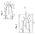
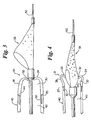
- FIG. 1 is a side sectional view of a distal tip in accordance with the present invention mounted to the distal end of a catheter;
- FIG. 2 is a view, similar to FIG. 1, illustrating an alternative embodiment;
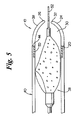
- FIG. 3 is a view of the present invention illustrating a distal protection device beginning to be drawn therewithin;
- FIG. 4 is a view similar to FIG. 3 illustrating the protection device being drawn into the distal tip and deforming the distal end thereof;
- FIG. 5 is a view similar to FIGS. 3 and 4 illustrating the diatal tip having captured the protection device.
-
- The device shown in FIG. 1 is suitable for use on a medical recovery catheter. The
distal tip 10 comprises a tapered member. The member has awall 34 that defines alumen 30. Thelumen 30 extends through the length of thedistal tip 10. Thelumen 30 extends from theproximal end 20 of thedistal tip 10 to thedistal end 24 of thedistal tip 10 to form an aperture through thedistal tip 10. Thedistal end 24 is the end located farthest from the attachment to themain catheter body 40, and theproximal end 20 is the end located nearest thecatheter body 40. - A
catheter body 40, suitable for use with the present invention, is a tubular member that has a lumen therethrough, The catheter lumen is in communication with thelumen 30 of thedistal tip 10. Thecatheter lumen 42 is in communication with thelumen 30 of thedistal tip 10 when thedistal end 44 of the catheter is connected to theproximal end 20 of thedistal tip 10. The catheter body may optionally contain aradiopaque marker band 50 in the general vicinity of thedistal end 44 of the catheter. The radiopaque marker band may be entirely within thecatheter body 40, entirely within the proximal portion of the distal tip, or any combination thereof. - The
wall 34 of thedistal tip 10 has a given thickness. The wall thickness can be uniform or be tapered. In one embodiment, thewall 34 has a taper decreasing to a lesser thickness as the wall progresses in the distal direction as shown in Fig. 2. - The
lumen 30 of thedistal tip 10 can have a uniform diameter along the length of thedistal tip 10 or it may be tapered. In one embodiment, the lumen of thedistal tip 30 tapers narrowingly in the distal direction. Thus, the lumen diameter can decrease as it progresses in the distal direction. - The
distal end 24 of thedistal tip 10 can have a rolled tip as at 32. The portion of thewall 34 at thedistal end 24 of thedistal tip 10 can be rolled inward toward theaxis 52 of thelumen 30 to form the rolledtip 32. - The
wall 34 ofdistal tip 10 has aninside surface 36 and anouter surface 38. At the rolledtip 32, end 22 is shown as facing inwardly toward thelumen 30. Theend 22 is facing generally radially inwardly. Theouter surface 38, over most of the length of thedistal tip 10, faces generally radially outwardly. However, at the rolledtip 32, theouter surface 38 is curved so as to face in the distal direction to define adistal contact surface 26. - The present invention can be used in the lumen of a human body, such as in a
blood vessel 54. The rolledtip 32 is especially designed for crossing a stented or otherwise constricted region of ablood vessel 54. A stent is a generally tubular member having a wire wall defining the boundary of the blood vessel lumen. The catheter must pass through the lumen defined within the stent in order to cross the stented region. As a catheter in accordance with the prior art is advanced within the blood vessel, the distal end of the catheter can become caught against an axial end of the stent. This is particularly true at a curve in theblood vessel 54, or when the stent is underexpanded or incompletely deployed. More specifically, the end of the catheter may engage an axial end of the stent. This can prevent the catheter from being able to advance farther into theblood vessel 54. Similar problems may occur in a constricted or stenosed region of a blood vessel. - The rolled tip configuration in accordance with the present invention can prevent such problems. A catheter utilizing the
distal tip 10, having a rolledtip 32 described herein, is inserted into a blood vessel. Thedistal tip 10 is advanced to a stented region of the blood vessel. The rolledtip 10 is curved, as previously discussed, such that the outer portion of thewall 34 at the rolledtip 32 definescontact surface 26. As thedistal tip 10 is advanced through the region, thecontact surface 26 of the rolledtip 32 may engage a stent. The rolledtip 32 prevents thedistal tip 10 from becoming impassibly engaged with the stent. As thedistal tip 10 is urged across the stented region, the rolledtip 32 may contact the stent, but it will deflect from the point of contact and be urged away from the stent. Thus, where theouter surface 38 contacts the stent, thedistal tip 10 can continue advancing past the stent as a result of non-engagement with the axial end of the stent and allowing thedistal tip 10 to continue advancing within theblood vessel 54. - The
distal tip 10 can also function to capture, for example, aprotection device 58 within thelumen 30.Lumen 30 is of a given diameter. Thedistal tip 10 is connected to a catheter such that thedistal tip lumen 30 is in smooth communication with acatheter lumen 42. - A
device 58 to be captured within thelumen 30 might be, for example, an embolic protection device. A guidewire extends proximal with respect to theprotection device 58, extending through thelumen 30 of thedistal tip 10 andcatheter 40. The device is typically positioned distal to thedistal tip 10 and is secured to the guidewire. Theprotection device 58 has a diameter that is typically greater than that of the distal tipdistal end 24. - Again, the
distal tip 10 is made of a compliant material such that theprotection device 58 can be facilely received into thedistal tip lumen 30. As theprotection device 58 is drawn toward thedistal tip 10, it will first contact the rolledtip 32 at thecontact surface 26. The rolledtip 32 may be urged elastically inward as the device enters the lumen 30 (Fig. 3). After thedevice 58 has been fully drawn in the proximal direction relative todistal tip 10, the rolledtip 32 reaches a point where it ceases to be engaged by the device, and it will return to its undeflected configuration (Fig. 5). As thedevice 58 is being drawn into thelumen 30, however, thelumen 30 will adapt to conformingly hold thedevice 58 therein and rolledtip 32 will expand radially to accommodate the periphery of the device (Fig. 4). Thedevice 58 will eventually have become fully housed within the catheter lumen, and thedistal tip 10 returns, as discussed above, substantially to its original configuration. - It will be understood that resilient material forming the
distal tip 10 prevents the escape of emboli when theembolic protection device 58 is captured. At least a portion of the wall of thedistal tip 10 closely encompasses the periphery of theprotection device 58 and assumes the shape of the periphery. As a result, emboli are prevented from passing between the periphery of theprotection device 58 and the wall of thedistal tip 10. Emboli within theprotection device 58 are prevented from being released back into the blood vessel. Once theprotection device 58 has been received within the catheter lumen, thedistal tip 10 resumes substantially the size, shape, and dimensions of its original configuration. - The
distal tip 10 is a soft, deformable tip made of an elastic, compliant material. Suitable materials for making the distal tip include thermoplastic polymer and polymer blends or thermoset polymers such as silicone or silicone blends with a low durometer. One such material is a 35/40 D Pebax blend. Any other appropriate compliant materials may, however, be used. - The polymer tip may be filled with radiopaque materials such as barium sulphate, bismuth subcarbonate, tungsten powder, and the like. The
tip 10 can be molded or formed using a heated die or in any other such method. Radiofrequency induction heating, electrical resistance heating, conduction heating, or any other method may be used. The preferred dimensions of the formedtip 10 will, of course, depend on the dimensions of the catheter, For example, a range of catheter sizes is from 4.2 F to 6.0 F, with corresponding inner diameters of 0,042 inches and 0.062 inches, respectively. These catheters might have distal tips with rolled distal inner diameter's of 0.025 to 0.050 inches, respectively. The diameter of thedistal tip lumen 30 can be constant or tapered toward the distal end. Thetip 10 may be attached to the catheter by any appropriate method such as a unitary design, heating, adhesive bonding, or molding. - It will be understood that this disclosure, in many respects, is only illustrative. Changes may be made in details, particularly in matters of shape, size, material, and arrangement of parts without exceeding the scope of the invention. Accordingly, the scope of the invention is as defined in the language of the appended claims.
Claims (34)
- A distal tip for a medical catheter, comprising:a member having a wall defining a lumen, said member being positionable within a blood vessel such that said member is able to capture a device within said blood vessel, distal of said member, as said device is drawn toward said lumen, said member being adaptable to conformingly hold said device within said lumen.
- The distal tip according to Claim 1 wherein said member tapers radially inwardly toward a distal end thereof.
- The distal tip according to Claim 2 wherein said tip is attached to a distal end of a catheter.
- The distal tip according to Claim 3 wherein said catheter is positioned within a lumen of a human body.
- The distal tip according to Claim 3 wherein said catheter is positioned within a blood vessel.
- The distal tip according to Claim 5 wherein said catheter has a lumen and said catheter is advanced along a guidewire disposed within said lumen in said catheter.
- The distal tip according to Claim 1 wherein said device is an embolic protection device.
- A catheter having a distal tip, comprising:a wall defining the distal tip, said tip defining a lumen, the lumen having a distal end, wherein said wall has a curved portion at said distal end curving inwardly toward an axis of said lumen, said lumen having a diameter adaptable to accommodate a device having a diameter.
- The distal tip according to Claim 8 wherein said distal tip is attached to a distal end of a catheter member.
- The distal tip according to Claim 9 wherein said catheter is advanced within a blood vessel.
- The distal tip according to Claim 10 wherein said catheter has a lumen and said catheter is advanced over a guidewire extending therethrough.
- The distal tip according to Claim 11 wherein said wall has an outer surface, wherein, as said device is drawn into said distal tip, a portion of said device contacts a portion of said outer surface of said curved portion of said wall.
- The distal tip according to Claim 12 wherein said curved portion accommodates said device into said lumen of said distal tip.
- The distal tip according to Claim 13 wherein said device is drawn toward said catheter, and wherein said diatal tip conforms to said device as it is so drawn.
- The distal tip according to Claim 14 wherein said device is a protection device.
- The distal tip according to Claim 15 wherein said distal tip has a diameter that decreases as it progresses towards said curved portion.
- A catheter comprising:a distal tip comprising a tubular member having a wall defining a lumen having a periphery wherein said tubular member has a taper from a proximal end towards a rolled distal end wherein at said distal end said wall curves inwardly towards said lumen wherein a device having a greater periphery is urged into said lumen and said lumen adapts to conformingly receive said greater periphery.
- The distal tip according to Claim 17 wherein said distal tip is attached to a distal end of a catheter.
- The distal tip according to Claim 18 wherein said catheter is in a lumen of a patient's body.
- The distal tip according to Claim 19 wherein said device is an embolic protection device.
- The distal tip according to Claim 20 wherein said distal protection device has particulate matter therein.
- The distal tip according to Claim 21 wherein said distal tip is attached to a distal end of a catheter.
- The distal tip according to Claim 22 wherein as said embolic protection device is urged into said distal tip, at least a portion of said particulate matter is prevented from entering said lumen of said patient's body.
- The distal tip according to Claim 23 wherein as said distal protection device is urged in proximal direction said distal tip conforms to said greater periphery.
- The distal tip according to Claim 24 wherein as said protection device is urged proximal to said distal tip, said lumen returns substantially to its periphery.
- The distal tip according to Claim 25 wherein said protection device is received within said catheter body.
- A medical device comprising: a catheter having at least a single tubular member, said tubular member extending to a distal end; and a distal tubular member connected to and in communication with said catheter distal end wherein said distal tubular member has a wall forming a boundary about a lumen wherein said wall has a thickness that is tapered towards a distal end having a lesser thickness, said distal end of said wall being rolled inwardly towards said lumen forming a rolled tip wherein as said medical device is positioned within a blood vessel said rolled tip is able to receive a protection device into said lumen wherein a corresponding portion of said lumen complies to a periphery of said protection device that is in contact with said corresponding portion.
- The medical device according to claim 27 wherein said protection device has a periphery wherein said lumen has a periphery prior to receiving said protection device that is less than said periphery of said protection device.
- The medical device according to Claim 27 wherein said rolled tip is able to contact a portion of a stent at an area of contact and said area of contact will be on an outer surface of said wall.
- The medical device according to Claim 29 wherein said contact surface is configured such that said distal tip is advanced across said stent.
- The medical device according to Claim 27 wherein said protection device contains captured emboli and said distal tip is able to comply to said periphery such that emboli are prevented from releasing into said blood vessel.
- The medical device according to Claim 27 wherein said distal tip has a low durometer.
- The medical device according to Claim 27 wherein after said protection device is received within said catheter, said distal tip returns substantially to its original configuration.
- The medical device according to Claim 27 wherein said distal tip comprises a conformable material.
Applications Claiming Priority (4)
| Application Number | Priority Date | Filing Date | Title |
|---|---|---|---|
| US74740 | 1998-05-08 | ||
| US26877301P | 2001-02-14 | 2001-02-14 | |
| US268773P | 2001-02-14 | ||
| US10/074,740 US6979343B2 (en) | 2001-02-14 | 2002-02-12 | Rolled tip recovery catheter |
Publications (3)
| Publication Number | Publication Date |
|---|---|
| EP1232765A2 true EP1232765A2 (en) | 2002-08-21 |
| EP1232765A3 EP1232765A3 (en) | 2003-01-22 |
| EP1232765B1 EP1232765B1 (en) | 2006-04-19 |
Family
ID=26756011
Family Applications (1)
| Application Number | Title | Priority Date | Filing Date |
|---|---|---|---|
| EP02290356A Expired - Lifetime EP1232765B1 (en) | 2001-02-14 | 2002-02-14 | Recovery catheter having a rolled tip |
Country Status (7)
| Country | Link |
|---|---|
| US (4) | US6979343B2 (en) |
| EP (1) | EP1232765B1 (en) |
| JP (1) | JP2002325846A (en) |
| AT (1) | ATE323523T1 (en) |
| CA (1) | CA2372132A1 (en) |
| DE (1) | DE60203950T2 (en) |
| ES (1) | ES2262764T3 (en) |
Cited By (3)
| Publication number | Priority date | Publication date | Assignee | Title |
|---|---|---|---|---|
| WO2004021928A1 (en) * | 2002-09-04 | 2004-03-18 | Boston Scientific Limited | Embolic protection filter assembly |
| WO2005105193A1 (en) * | 2004-04-14 | 2005-11-10 | Boston Scientific Limited | Catheter distal tip design and method of making |
| US7854746B2 (en) | 2003-10-13 | 2010-12-21 | C. R. Bard, Inc. | Retrieval catheter |
Families Citing this family (90)
| Publication number | Priority date | Publication date | Assignee | Title |
|---|---|---|---|---|
| WO1998039053A1 (en) | 1997-03-06 | 1998-09-11 | Scimed Life Systems, Inc. | Distal protection device and method |
| EP1028670B1 (en) | 1997-11-07 | 2008-01-02 | Salviac Limited | An embolic protection device |
| US7491216B2 (en) | 1997-11-07 | 2009-02-17 | Salviac Limited | Filter element with retractable guidewire tip |
| US6918921B2 (en) | 1999-05-07 | 2005-07-19 | Salviac Limited | Support frame for an embolic protection device |
| US6964672B2 (en) | 1999-05-07 | 2005-11-15 | Salviac Limited | Support frame for an embolic protection device |
| US6402771B1 (en) | 1999-12-23 | 2002-06-11 | Guidant Endovascular Solutions | Snare |
| US6660021B1 (en) | 1999-12-23 | 2003-12-09 | Advanced Cardiovascular Systems, Inc. | Intravascular device and system |
| US6575997B1 (en) | 1999-12-23 | 2003-06-10 | Endovascular Technologies, Inc. | Embolic basket |
| US7918820B2 (en) | 1999-12-30 | 2011-04-05 | Advanced Cardiovascular Systems, Inc. | Device for, and method of, blocking emboli in vessels such as blood arteries |
| US6695813B1 (en) | 1999-12-30 | 2004-02-24 | Advanced Cardiovascular Systems, Inc. | Embolic protection devices |
| GB2369575A (en) | 2000-04-20 | 2002-06-05 | Salviac Ltd | An embolic protection system |
| US6964670B1 (en) | 2000-07-13 | 2005-11-15 | Advanced Cardiovascular Systems, Inc. | Embolic protection guide wire |
| US6616681B2 (en) * | 2000-10-05 | 2003-09-09 | Scimed Life Systems, Inc. | Filter delivery and retrieval device |
| US6506203B1 (en) | 2000-12-19 | 2003-01-14 | Advanced Cardiovascular Systems, Inc. | Low profile sheathless embolic protection system |
| US7338510B2 (en) | 2001-06-29 | 2008-03-04 | Advanced Cardiovascular Systems, Inc. | Variable thickness embolic filtering devices and method of manufacturing the same |
| US6599307B1 (en) | 2001-06-29 | 2003-07-29 | Advanced Cardiovascular Systems, Inc. | Filter device for embolic protection systems |
| US6638294B1 (en) | 2001-08-30 | 2003-10-28 | Advanced Cardiovascular Systems, Inc. | Self furling umbrella frame for carotid filter |
| US6592606B2 (en) | 2001-08-31 | 2003-07-15 | Advanced Cardiovascular Systems, Inc. | Hinged short cage for an embolic protection device |
| US8262689B2 (en) | 2001-09-28 | 2012-09-11 | Advanced Cardiovascular Systems, Inc. | Embolic filtering devices |
| US7153320B2 (en) * | 2001-12-13 | 2006-12-26 | Scimed Life Systems, Inc. | Hydraulic controlled retractable tip filter retrieval catheter |
| WO2003055413A2 (en) | 2001-12-21 | 2003-07-10 | Salviac Limited | A support frame for an embolic protection device |
| US7241304B2 (en) | 2001-12-21 | 2007-07-10 | Advanced Cardiovascular Systems, Inc. | Flexible and conformable embolic filtering devices |
| AU2003231886A1 (en) * | 2002-05-13 | 2003-11-11 | Salviac Limited | Retrieval catheter for an embolic filter |
| US7331973B2 (en) | 2002-09-30 | 2008-02-19 | Avdanced Cardiovascular Systems, Inc. | Guide wire with embolic filtering attachment |
| US7252675B2 (en) | 2002-09-30 | 2007-08-07 | Advanced Cardiovascular, Inc. | Embolic filtering devices |
| US20040088000A1 (en) | 2002-10-31 | 2004-05-06 | Muller Paul F. | Single-wire expandable cages for embolic filtering devices |
| US8591540B2 (en) | 2003-02-27 | 2013-11-26 | Abbott Cardiovascular Systems Inc. | Embolic filtering devices |
| EP1608295B1 (en) | 2003-03-28 | 2017-05-03 | Covidien LP | Double ended intravascular medical device |
| US7892251B1 (en) | 2003-11-12 | 2011-02-22 | Advanced Cardiovascular Systems, Inc. | Component for delivering and locking a medical device to a guide wire |
| US7695491B2 (en) | 2003-12-01 | 2010-04-13 | Ev3 Inc. | Rapid exchange catheters with tandem lumens |
| US7678129B1 (en) | 2004-03-19 | 2010-03-16 | Advanced Cardiovascular Systems, Inc. | Locking component for an embolic filter assembly |
| WO2006042114A1 (en) | 2004-10-06 | 2006-04-20 | Cook, Inc. | Emboli capturing device having a coil and method for capturing emboli |
| WO2006089178A2 (en) | 2005-02-18 | 2006-08-24 | Ev3 Inc. | Rapid exchange catheters and embolic protection devices |
| US8945169B2 (en) | 2005-03-15 | 2015-02-03 | Cook Medical Technologies Llc | Embolic protection device |
| US8221446B2 (en) | 2005-03-15 | 2012-07-17 | Cook Medical Technologies | Embolic protection device |
| US9259305B2 (en) | 2005-03-31 | 2016-02-16 | Abbott Cardiovascular Systems Inc. | Guide wire locking mechanism for rapid exchange and other catheter systems |
| US7850708B2 (en) | 2005-06-20 | 2010-12-14 | Cook Incorporated | Embolic protection device having a reticulated body with staggered struts |
| US8109962B2 (en) | 2005-06-20 | 2012-02-07 | Cook Medical Technologies Llc | Retrievable device having a reticulation portion with staggered struts |
| US7771452B2 (en) | 2005-07-12 | 2010-08-10 | Cook Incorporated | Embolic protection device with a filter bag that disengages from a basket |
| US7766934B2 (en) | 2005-07-12 | 2010-08-03 | Cook Incorporated | Embolic protection device with an integral basket and bag |
| US8187298B2 (en) | 2005-08-04 | 2012-05-29 | Cook Medical Technologies Llc | Embolic protection device having inflatable frame |
| US8377092B2 (en) | 2005-09-16 | 2013-02-19 | Cook Medical Technologies Llc | Embolic protection device |
| US8632562B2 (en) | 2005-10-03 | 2014-01-21 | Cook Medical Technologies Llc | Embolic protection device |
| US8182508B2 (en) | 2005-10-04 | 2012-05-22 | Cook Medical Technologies Llc | Embolic protection device |
| US8252017B2 (en) | 2005-10-18 | 2012-08-28 | Cook Medical Technologies Llc | Invertible filter for embolic protection |
| US8216269B2 (en) | 2005-11-02 | 2012-07-10 | Cook Medical Technologies Llc | Embolic protection device having reduced profile |
| US8152831B2 (en) | 2005-11-17 | 2012-04-10 | Cook Medical Technologies Llc | Foam embolic protection device |
| JP4550752B2 (en) * | 2006-03-09 | 2010-09-22 | 日本シャーウッド株式会社 | Medical tube set |
| JP4483835B2 (en) * | 2006-08-01 | 2010-06-16 | ニプロ株式会社 | Thrombus capture member recovery sheath and thrombus capture catheter |
| US20080071307A1 (en) | 2006-09-19 | 2008-03-20 | Cook Incorporated | Apparatus and methods for in situ embolic protection |
| US8460372B2 (en) | 2006-11-07 | 2013-06-11 | Dc Devices, Inc. | Prosthesis for reducing intra-cardiac pressure having an embolic filter |
| EP3329860A1 (en) | 2006-11-07 | 2018-06-06 | David Stephen Celermajer | Devices for the treatment of heart failure |
| US20110257723A1 (en) | 2006-11-07 | 2011-10-20 | Dc Devices, Inc. | Devices and methods for coronary sinus pressure relief |
| US10413284B2 (en) | 2006-11-07 | 2019-09-17 | Corvia Medical, Inc. | Atrial pressure regulation with control, sensing, monitoring and therapy delivery |
| US8740962B2 (en) | 2006-11-07 | 2014-06-03 | Dc Devices, Inc. | Prosthesis for retrieval and deployment |
| US9232997B2 (en) | 2006-11-07 | 2016-01-12 | Corvia Medical, Inc. | Devices and methods for retrievable intra-atrial implants |
| US20080140003A1 (en) * | 2006-12-06 | 2008-06-12 | Advanced Cardiovascular Systems, Inc. | Balloon catheter having a regrooming sheath and method for collapsing an expanded medical device |
| US9901434B2 (en) | 2007-02-27 | 2018-02-27 | Cook Medical Technologies Llc | Embolic protection device including a Z-stent waist band |
| US8216209B2 (en) | 2007-05-31 | 2012-07-10 | Abbott Cardiovascular Systems Inc. | Method and apparatus for delivering an agent to a kidney |
| US7867273B2 (en) | 2007-06-27 | 2011-01-11 | Abbott Laboratories | Endoprostheses for peripheral arteries and other body vessels |
| US8252018B2 (en) | 2007-09-14 | 2012-08-28 | Cook Medical Technologies Llc | Helical embolic protection device |
| US8419748B2 (en) | 2007-09-14 | 2013-04-16 | Cook Medical Technologies Llc | Helical thrombus removal device |
| US9138307B2 (en) | 2007-09-14 | 2015-09-22 | Cook Medical Technologies Llc | Expandable device for treatment of a stricture in a body vessel |
| JP2009178518A (en) * | 2008-02-01 | 2009-08-13 | Nipro Corp | Medical tubular body, thrombus capturing member collecting sheath, thrombus collecting catheter, and balloon catheter |
| US8388644B2 (en) | 2008-12-29 | 2013-03-05 | Cook Medical Technologies Llc | Embolic protection device and method of use |
| US9757107B2 (en) | 2009-09-04 | 2017-09-12 | Corvia Medical, Inc. | Methods and devices for intra-atrial shunts having adjustable sizes |
| US9277995B2 (en) | 2010-01-29 | 2016-03-08 | Corvia Medical, Inc. | Devices and methods for reducing venous pressure |
| JP5470197B2 (en) * | 2010-08-19 | 2014-04-16 | アクセスポイント テクノロジーズ有限会社 | Embolization capture device |
| CA2827025C (en) | 2011-02-10 | 2020-09-01 | Dc Devices, Inc. | Apparatus and methods to create and maintain an intra-atrial pressure relief opening |
| US10322253B2 (en) | 2011-03-29 | 2019-06-18 | Teleflex Life Sciences Unlimited Company | Ballooned ventilation tube cleaning device |
| GB201119794D0 (en) | 2011-11-16 | 2011-12-28 | Airway Medix Spolka Z O O | Ballooned ventilation tube cleaning device |
| US8951223B2 (en) | 2011-12-22 | 2015-02-10 | Dc Devices, Inc. | Methods and devices for intra-atrial shunts having adjustable sizes |
| US9005155B2 (en) | 2012-02-03 | 2015-04-14 | Dc Devices, Inc. | Devices and methods for treating heart failure |
| US10588611B2 (en) | 2012-04-19 | 2020-03-17 | Corvia Medical Inc. | Implant retention attachment and method of use |
| US9649480B2 (en) | 2012-07-06 | 2017-05-16 | Corvia Medical, Inc. | Devices and methods of treating or ameliorating diastolic heart failure through pulmonary valve intervention |
| EP2754461B1 (en) * | 2013-01-14 | 2017-12-13 | Teleflex Medical Incorporated | Suction catheter device |
| US9775636B2 (en) | 2013-03-12 | 2017-10-03 | Corvia Medical, Inc. | Devices, systems, and methods for treating heart failure |
| JP2016515412A (en) * | 2013-03-15 | 2016-05-30 | ボルケーノ コーポレイション | Recovery and centering apparatus and method with pressure and ultrasonic features |
| US10675450B2 (en) | 2014-03-12 | 2020-06-09 | Corvia Medical, Inc. | Devices and methods for treating heart failure |
| WO2016014821A1 (en) | 2014-07-23 | 2016-01-28 | Corvia Medical, Inc. | Devices and methods for treating heart failure |
| US10500360B1 (en) | 2014-08-29 | 2019-12-10 | Teleflex Life Sciences Unlimited Company | Catheter for cleaning of tracheal ventilation tubes |
| US10166373B2 (en) * | 2014-10-31 | 2019-01-01 | Biosensors International Group, Ltd. | Elastic tip for an adjustable length angioplasty balloon sheath |
| GB2546082B (en) | 2016-01-06 | 2018-05-16 | Airway Medix S A | Closed suction system |
| US11452831B2 (en) | 2016-01-06 | 2022-09-27 | Airway Medix S.A. | Closed suction system |
| US10946153B2 (en) | 2016-05-16 | 2021-03-16 | Teleflex Life Sciences Pte. Ltd. | Mechanical user control elements for fluid input module |
| US20210220626A1 (en) | 2019-08-14 | 2021-07-22 | Vasoinnovations, Inc. | Apparatus and method for advancing catheters or other medical devices through a lumen |
| US10773059B1 (en) | 2019-08-14 | 2020-09-15 | Vasoinnovations, Inc. | Apparatus and method for advancing catheters or other medical devices through a lumen |
| US10821267B1 (en) | 2019-08-14 | 2020-11-03 | Vasoinnovations Inc. | Apparatus and method for advancing catheters or other medical devices through a lumen |
| US10828470B1 (en) | 2019-08-14 | 2020-11-10 | Vasoinnovations Inc. | Apparatus and method for advancing catheters or other medical devices through a lumen |
| US10792469B1 (en) | 2019-08-14 | 2020-10-06 | Vasoinnovations Inc. | Devices, systems, and methods for delivering catheters or other medical devices to locations within a patients body |
Citations (6)
| Publication number | Priority date | Publication date | Assignee | Title |
|---|---|---|---|---|
| DE1566147A1 (en) * | 1967-10-26 | 1970-07-23 | Ewald Monix | Catheter for removing ureteral stones |
| US4611594A (en) * | 1984-04-11 | 1986-09-16 | Northwestern University | Medical instrument for containment and removal of calculi |
| US5217468A (en) * | 1991-10-24 | 1993-06-08 | Mectra Labs, Inc. | Tissue encapsulating sheath |
| US5447503A (en) * | 1991-08-14 | 1995-09-05 | Cordis Corporation | Guiding catheter tip having a tapered tip with an expandable lumen |
| WO2000044428A1 (en) * | 1999-01-28 | 2000-08-03 | Ansamed Limited | Catheter with an expandable end portion |
| US6159230A (en) * | 1997-10-23 | 2000-12-12 | Samuels; Shaun L. W. | Expandable lumen device and method of use |
Family Cites Families (60)
| Publication number | Priority date | Publication date | Assignee | Title |
|---|---|---|---|---|
| US3074408A (en) * | 1961-05-22 | 1963-01-22 | Martin H Chester | Ureteral stone extractor and dilator |
| DE2127125C3 (en) | 1971-06-01 | 1973-12-06 | Arthur Dipl.-Ing. 8059 Eichenried Heller | Hollow ureter for the non-surgical removal of stuck ureter stones |
| US4324262A (en) * | 1979-01-02 | 1982-04-13 | University Of Virginia Alumni Patents Foundation | Aspirating culture catheter and method of use |
| DE2933266A1 (en) | 1979-08-16 | 1981-05-27 | Dietrich 8130 Starnberg Hasse | Ureter stone removal catheter - has shaft in hose with tool destroying stone at free end |
| US4588399A (en) | 1980-05-14 | 1986-05-13 | Shiley Incorporated | Cannula with radiopaque tip |
| US4563181A (en) | 1983-02-18 | 1986-01-07 | Mallinckrodt, Inc. | Fused flexible tip catheter |
| US4469100A (en) * | 1983-03-14 | 1984-09-04 | Hardwick Charles W | Intussuscepting balloon catheter for stone extraction |
| US4531943A (en) | 1983-08-08 | 1985-07-30 | Angiomedics Corporation | Catheter with soft deformable tip |
| US4960411A (en) | 1984-09-18 | 1990-10-02 | Medtronic Versaflex, Inc. | Low profile sterrable soft-tip catheter |
| US4886506A (en) | 1986-12-23 | 1989-12-12 | Baxter Travenol Laboratories, Inc. | Soft tip catheter |
| US4863442A (en) | 1987-08-14 | 1989-09-05 | C. R. Bard, Inc. | Soft tip catheter |
| US5078702A (en) | 1988-03-25 | 1992-01-07 | Baxter International Inc. | Soft tip catheters |
| US4950257A (en) | 1988-09-15 | 1990-08-21 | Mallinckrodt, Inc. | Catheter introducer with flexible tip |
| US4927426A (en) * | 1989-01-03 | 1990-05-22 | Dretler Stephen P | Catheter device |
| US5045072A (en) | 1989-06-13 | 1991-09-03 | Cordis Corporation | Catheter having highly radiopaque, flexible tip |
| US4976690A (en) | 1989-08-10 | 1990-12-11 | Scimed Life Systems, Inc. | Variable stiffness angioplasty catheter |
| DE8910603U1 (en) * | 1989-09-06 | 1989-12-07 | Guenther, Rolf W., Prof. Dr. | |
| US5234416A (en) | 1991-06-06 | 1993-08-10 | Advanced Cardiovascular Systems, Inc. | Intravascular catheter with a nontraumatic distal tip |
| US5769830A (en) | 1991-06-28 | 1998-06-23 | Cook Incorporated | Soft tip guiding catheter |
| US5221270A (en) | 1991-06-28 | 1993-06-22 | Cook Incorporated | Soft tip guiding catheter |
| US5308342A (en) | 1991-08-07 | 1994-05-03 | Target Therapeutics, Inc. | Variable stiffness catheter |
| US5318032A (en) | 1992-02-05 | 1994-06-07 | Devices For Vascular Intervention | Guiding catheter having soft tip |
| US5584821A (en) | 1992-06-02 | 1996-12-17 | E-Z-Em, Inc. | Soft tip catheter |
| US5342386A (en) | 1992-10-26 | 1994-08-30 | Cordis Corporation | Catheter with multiple flexibilities along the shaft |
| US5300048A (en) | 1993-05-12 | 1994-04-05 | Sabin Corporation | Flexible, highly radiopaque plastic material catheter |
| US5445624A (en) | 1994-01-21 | 1995-08-29 | Exonix Research Corporation | Catheter with progressively compliant tip |
| US5911715A (en) | 1994-02-14 | 1999-06-15 | Scimed Life Systems, Inc. | Guide catheter having selected flexural modulus segments |
| US5509910A (en) | 1994-05-02 | 1996-04-23 | Medtronic, Inc. | Method of soft tip attachment for thin walled catheters |
| US5480383A (en) | 1994-05-27 | 1996-01-02 | Advanced Cardiovascular Systems, Inc. | Dilation catheter with a smooth transition between a stiff proximal portion and a flexible distal portion |
| EP1695673A3 (en) | 1994-07-08 | 2009-07-08 | ev3 Inc. | Intravascular filtering device |
| US5643282A (en) * | 1994-08-22 | 1997-07-01 | Kieturakis; Maciej J. | Surgical instrument and method for removing tissue from an endoscopic workspace |
| JPH10511871A (en) | 1995-01-04 | 1998-11-17 | メドトロニック・インコーポレーテッド | Soft chip forming method |
| DE69626108T2 (en) * | 1995-04-14 | 2003-11-20 | Boston Scient Ltd | STENTING DEVICE WITH ROLLING MEMBRANE |
| JP3855243B2 (en) | 1996-02-21 | 2006-12-06 | 日本ゼオン株式会社 | Medical insertion aid |
| US5846251A (en) * | 1996-07-22 | 1998-12-08 | Hart; Charles C. | Access device with expandable containment member |
| US5836925A (en) | 1996-04-03 | 1998-11-17 | Soltesz; Peter P. | Catheter with variable flexibility properties and method of manufacture |
| US6210370B1 (en) * | 1997-01-10 | 2001-04-03 | Applied Medical Resources Corporation | Access device with expandable containment member |
| US5814064A (en) | 1997-03-06 | 1998-09-29 | Scimed Life Systems, Inc. | Distal protection device |
| US6174318B1 (en) * | 1998-04-23 | 2001-01-16 | Scimed Life Systems, Inc. | Basket with one or more moveable legs |
| EP1028670B1 (en) | 1997-11-07 | 2008-01-02 | Salviac Limited | An embolic protection device |
| EP1030603B1 (en) * | 1997-11-12 | 2008-08-13 | Genesis Technologies LLC. | Biological passageway occlusion removal |
| US6113579A (en) | 1998-03-04 | 2000-09-05 | Scimed Life Systems, Inc. | Catheter tip designs and methods for improved stent crossing |
| US6093173A (en) * | 1998-09-09 | 2000-07-25 | Embol-X, Inc. | Introducer/dilator with balloon protection and methods of use |
| US6544279B1 (en) * | 2000-08-09 | 2003-04-08 | Incept, Llc | Vascular device for emboli, thrombus and foreign body removal and methods of use |
| JP4439780B2 (en) | 1999-07-30 | 2010-03-24 | インセプト エルエルシー | Vascular device for removal of emboli, thrombus and foreign bodies |
| EP1202676B1 (en) * | 1999-08-12 | 2010-09-22 | Salviac Limited | Retrieval device |
| US6277083B1 (en) * | 1999-12-27 | 2001-08-21 | Neothermia Corporation | Minimally invasive intact recovery of tissue |
| US6290710B1 (en) | 1999-12-29 | 2001-09-18 | Advanced Cardiovascular Systems, Inc. | Embolic protection device |
| GB2369575A (en) | 2000-04-20 | 2002-06-05 | Salviac Ltd | An embolic protection system |
| US6485501B1 (en) * | 2000-08-11 | 2002-11-26 | Cordis Corporation | Vascular filter system with guidewire and capture mechanism |
| US6616681B2 (en) * | 2000-10-05 | 2003-09-09 | Scimed Life Systems, Inc. | Filter delivery and retrieval device |
| US6616680B1 (en) * | 2000-11-01 | 2003-09-09 | Joseph M. Thielen | Distal protection and delivery system and method |
| US6663651B2 (en) * | 2001-01-16 | 2003-12-16 | Incept Llc | Systems and methods for vascular filter retrieval |
| AU2002253490A1 (en) * | 2001-04-17 | 2002-10-28 | Salviac Limited | A catheter |
| US6929652B1 (en) * | 2001-06-01 | 2005-08-16 | Advanced Cardiovascular Systems, Inc. | Delivery and recovery systems having steerability and rapid exchange operating modes for embolic protection systems |
| US6878153B2 (en) * | 2001-07-02 | 2005-04-12 | Rubicon Medical, Inc. | Methods, systems, and devices for providing embolic protection and removing embolic material |
| US7153320B2 (en) | 2001-12-13 | 2006-12-26 | Scimed Life Systems, Inc. | Hydraulic controlled retractable tip filter retrieval catheter |
| US6695834B2 (en) * | 2002-01-25 | 2004-02-24 | Scimed Life Systems, Inc. | Apparatus and method for stone removal from a body |
| US7087061B2 (en) * | 2002-03-12 | 2006-08-08 | Lithotech Medical Ltd | Method for intracorporeal lithotripsy fragmentation and apparatus for its implementation |
| US7115138B2 (en) * | 2002-09-04 | 2006-10-03 | Boston Scientific Scimed, Inc. | Sheath tip |
-
2002
- 2002-02-12 US US10/074,740 patent/US6979343B2/en not_active Expired - Lifetime
- 2002-02-13 CA CA002372132A patent/CA2372132A1/en not_active Abandoned
- 2002-02-14 EP EP02290356A patent/EP1232765B1/en not_active Expired - Lifetime
- 2002-02-14 ES ES02290356T patent/ES2262764T3/en not_active Expired - Lifetime
- 2002-02-14 AT AT02290356T patent/ATE323523T1/en not_active IP Right Cessation
- 2002-02-14 DE DE60203950T patent/DE60203950T2/en not_active Expired - Lifetime
- 2002-02-14 JP JP2002036326A patent/JP2002325846A/en active Pending
-
2005
- 2005-11-08 US US11/268,823 patent/US7819890B2/en active Active
-
2010
- 2010-09-16 US US12/883,606 patent/US8747431B2/en not_active Expired - Lifetime
-
2014
- 2014-05-02 US US14/268,228 patent/US9901709B2/en not_active Expired - Lifetime
Patent Citations (6)
| Publication number | Priority date | Publication date | Assignee | Title |
|---|---|---|---|---|
| DE1566147A1 (en) * | 1967-10-26 | 1970-07-23 | Ewald Monix | Catheter for removing ureteral stones |
| US4611594A (en) * | 1984-04-11 | 1986-09-16 | Northwestern University | Medical instrument for containment and removal of calculi |
| US5447503A (en) * | 1991-08-14 | 1995-09-05 | Cordis Corporation | Guiding catheter tip having a tapered tip with an expandable lumen |
| US5217468A (en) * | 1991-10-24 | 1993-06-08 | Mectra Labs, Inc. | Tissue encapsulating sheath |
| US6159230A (en) * | 1997-10-23 | 2000-12-12 | Samuels; Shaun L. W. | Expandable lumen device and method of use |
| WO2000044428A1 (en) * | 1999-01-28 | 2000-08-03 | Ansamed Limited | Catheter with an expandable end portion |
Cited By (5)
| Publication number | Priority date | Publication date | Assignee | Title |
|---|---|---|---|---|
| WO2004021928A1 (en) * | 2002-09-04 | 2004-03-18 | Boston Scientific Limited | Embolic protection filter assembly |
| US7115138B2 (en) * | 2002-09-04 | 2006-10-03 | Boston Scientific Scimed, Inc. | Sheath tip |
| US7854746B2 (en) | 2003-10-13 | 2010-12-21 | C. R. Bard, Inc. | Retrieval catheter |
| WO2005105193A1 (en) * | 2004-04-14 | 2005-11-10 | Boston Scientific Limited | Catheter distal tip design and method of making |
| US8404165B2 (en) | 2004-04-14 | 2013-03-26 | Boston Scientific Scimed, Inc. | Catheter distal tip design and method of making |
Also Published As
| Publication number | Publication date |
|---|---|
| US20110004239A1 (en) | 2011-01-06 |
| US20020111649A1 (en) | 2002-08-15 |
| DE60203950D1 (en) | 2005-06-09 |
| JP2002325846A (en) | 2002-11-12 |
| US7819890B2 (en) | 2010-10-26 |
| US9901709B2 (en) | 2018-02-27 |
| ATE323523T1 (en) | 2006-05-15 |
| US20140243884A1 (en) | 2014-08-28 |
| US20060052817A1 (en) | 2006-03-09 |
| EP1232765B1 (en) | 2006-04-19 |
| US8747431B2 (en) | 2014-06-10 |
| DE60203950T2 (en) | 2006-12-07 |
| US6979343B2 (en) | 2005-12-27 |
| EP1232765A3 (en) | 2003-01-22 |
| ES2262764T3 (en) | 2006-12-01 |
| CA2372132A1 (en) | 2002-08-17 |
Similar Documents
| Publication | Publication Date | Title |
|---|---|---|
| US7819890B2 (en) | Rolled tip recovery catheter | |
| US6679902B1 (en) | Reduced profile delivery sheath for use in interventional procedures | |
| US7226464B2 (en) | Intravascular filter retrieval device having an actuatable dilator tip | |
| EP1351621B1 (en) | Systems and methods for vascular filter retrieval | |
| US6837898B2 (en) | Intraluminal delivery system for an attachable treatment device | |
| EP1067885B1 (en) | Delivery catheter | |
| US10098724B2 (en) | Rapid exchange catheters usable with embolic protection devices | |
| US6793666B2 (en) | Distal protection mechanically attached filter cartridge | |
| US6290710B1 (en) | Embolic protection device | |
| US6443979B1 (en) | Expandable stent delivery sheath and method of use | |
| US20020058963A1 (en) | Retrieval device | |
| US20070066992A1 (en) | Filter delivery and retrieval device | |
| US20050113804A1 (en) | Variable diameter delivery catheter | |
| CA2359248A1 (en) | Rapid exchange delivery catheter |
Legal Events
| Date | Code | Title | Description |
|---|---|---|---|
| PUAI | Public reference made under article 153(3) epc to a published international application that has entered the european phase |
Free format text: ORIGINAL CODE: 0009012 |
|
| AK | Designated contracting states |
Kind code of ref document: A2 Designated state(s): AT BE CH CY DE DK ES FI FR GB GR IE IT LI LU MC NL PT SE TR |
|
| AX | Request for extension of the european patent |
Free format text: AL;LT;LV;MK;RO;SI |
|
| PUAL | Search report despatched |
Free format text: ORIGINAL CODE: 0009013 |
|
| AK | Designated contracting states |
Kind code of ref document: A3 Designated state(s): AT BE CH CY DE DK ES FI FR GB GR IE IT LI LU MC NL PT SE TR |
|
| AX | Request for extension of the european patent |
Free format text: AL;LT;LV;MK;RO;SI |
|
| RIC1 | Information provided on ipc code assigned before grant |
Free format text: 7A 61M 25/00 A, 7A 61M 25/01 B |
|
| 17P | Request for examination filed |
Effective date: 20030718 |
|
| AKX | Designation fees paid |
Designated state(s): AT BE CH CY DE DK ES FI FR GB GR IE IT LI LU MC NL PT SE TR |
|
| 17Q | First examination report despatched |
Effective date: 20030929 |
|
| RAP1 | Party data changed (applicant data changed or rights of an application transferred) |
Owner name: EV.3 INC. |
|
| GRAP | Despatch of communication of intention to grant a patent |
Free format text: ORIGINAL CODE: EPIDOSNIGR1 |
|
| GRAS | Grant fee paid |
Free format text: ORIGINAL CODE: EPIDOSNIGR3 |
|
| GRAL | Information related to payment of fee for publishing/printing deleted |
Free format text: ORIGINAL CODE: EPIDOSDIGR3 |
|
| GRAS | Grant fee paid |
Free format text: ORIGINAL CODE: EPIDOSNIGR3 |
|
| GRAA | (expected) grant |
Free format text: ORIGINAL CODE: 0009210 |
|
| AK | Designated contracting states |
Kind code of ref document: B1 Designated state(s): AT BE CH CY DE DK ES FI FR GB GR IE IT LI LU MC NL PT SE TR |
|
| REG | Reference to a national code |
Ref country code: GB Ref legal event code: FG4D |
|
| REG | Reference to a national code |
Ref country code: CH Ref legal event code: EP |
|
| REG | Reference to a national code |
Ref country code: IE Ref legal event code: FG4D |
|
| REF | Corresponds to: |
Ref document number: 60203950 Country of ref document: DE Date of ref document: 20050609 Kind code of ref document: P |
|
| NLV1 | Nl: lapsed or annulled due to failure to fulfill the requirements of art. 29p and 29m of the patents act | ||
| PGFP | Annual fee paid to national office [announced via postgrant information from national office to epo] |
Ref country code: MC Payment date: 20060119 Year of fee payment: 6 |
|
| PUAC | Information related to the publication of a b1 document modified or deleted |
Free format text: ORIGINAL CODE: 0009299EPPU |
|
| GRAA | (expected) grant |
Free format text: ORIGINAL CODE: 0009210 |
|
| REG | Reference to a national code |
Ref country code: CH Ref legal event code: PK Free format text: BERICHTIGUNG |
|
| DB1 | Publication of patent cancelled | ||
| AK | Designated contracting states |
Kind code of ref document: B1 Designated state(s): AT BE CH CY DE DK ES FI FR GB GR IE IT LI LU MC NL PT SE TR |
|
| PG25 | Lapsed in a contracting state [announced via postgrant information from national office to epo] |
Ref country code: IT Free format text: LAPSE BECAUSE OF FAILURE TO SUBMIT A TRANSLATION OF THE DESCRIPTION OR TO PAY THE FEE WITHIN THE PRESCRIBED TIME-LIMIT;WARNING: LAPSES OF ITALIAN PATENTS WITH EFFECTIVE DATE BEFORE 2007 MAY HAVE OCCURRED AT ANY TIME BEFORE 2007. THE CORRECT EFFECTIVE DATE MAY BE DIFFERENT FROM THE ONE RECORDED. Effective date: 20060419 Ref country code: LI Free format text: LAPSE BECAUSE OF FAILURE TO SUBMIT A TRANSLATION OF THE DESCRIPTION OR TO PAY THE FEE WITHIN THE PRESCRIBED TIME-LIMIT Effective date: 20060419 Ref country code: CH Free format text: LAPSE BECAUSE OF FAILURE TO SUBMIT A TRANSLATION OF THE DESCRIPTION OR TO PAY THE FEE WITHIN THE PRESCRIBED TIME-LIMIT Effective date: 20060419 |
|
| NLXE | Nl: other communications concerning ep-patents (part 3 heading xe) |
Free format text: PAT. BUL. 07/2005: PATENTNUMBER 1232765 SHOULD BE DELETED (SEE EUROPEAN PATENT BULLETIN 20060329/13) |
|
| REG | Reference to a national code |
Ref country code: CH Ref legal event code: PL |
|
| REG | Reference to a national code |
Ref country code: ES Ref legal event code: FG2A Ref document number: 2262764 Country of ref document: ES Kind code of ref document: T3 |
|
| ET | Fr: translation filed | ||
| PLBE | No opposition filed within time limit |
Free format text: ORIGINAL CODE: 0009261 |
|
| STAA | Information on the status of an ep patent application or granted ep patent |
Free format text: STATUS: NO OPPOSITION FILED WITHIN TIME LIMIT |
|
| 26N | No opposition filed |
Effective date: 20070122 |
|
| PG25 | Lapsed in a contracting state [announced via postgrant information from national office to epo] |
Ref country code: MC Free format text: LAPSE BECAUSE OF NON-PAYMENT OF DUE FEES Effective date: 20080228 |
|
| PG25 | Lapsed in a contracting state [announced via postgrant information from national office to epo] |
Ref country code: FI Free format text: LAPSE BECAUSE OF FAILURE TO SUBMIT A TRANSLATION OF THE DESCRIPTION OR TO PAY THE FEE WITHIN THE PRESCRIBED TIME-LIMIT Effective date: 20060419 Ref country code: CY Free format text: LAPSE BECAUSE OF FAILURE TO SUBMIT A TRANSLATION OF THE DESCRIPTION OR TO PAY THE FEE WITHIN THE PRESCRIBED TIME-LIMIT Effective date: 20060419 |
|
| PG25 | Lapsed in a contracting state [announced via postgrant information from national office to epo] |
Ref country code: TR Free format text: LAPSE BECAUSE OF FAILURE TO SUBMIT A TRANSLATION OF THE DESCRIPTION OR TO PAY THE FEE WITHIN THE PRESCRIBED TIME-LIMIT Effective date: 20060419 |
|
| PG25 | Lapsed in a contracting state [announced via postgrant information from national office to epo] |
Ref country code: DK Free format text: LAPSE BECAUSE OF NON-PAYMENT OF DUE FEES Effective date: 20060419 |
|
| PG25 | Lapsed in a contracting state [announced via postgrant information from national office to epo] |
Ref country code: LU Free format text: LAPSE BECAUSE OF NON-PAYMENT OF DUE FEES Effective date: 20070228 |
|
| PG25 | Lapsed in a contracting state [announced via postgrant information from national office to epo] |
Ref country code: LU Free format text: LAPSE BECAUSE OF NON-PAYMENT OF DUE FEES Effective date: 20060419 |
|
| PG25 | Lapsed in a contracting state [announced via postgrant information from national office to epo] |
Ref country code: BE Free format text: LAPSE BECAUSE OF FAILURE TO SUBMIT A TRANSLATION OF THE DESCRIPTION OR TO PAY THE FEE WITHIN THE PRESCRIBED TIME-LIMIT Effective date: 20060419 |
|
| PG25 | Lapsed in a contracting state [announced via postgrant information from national office to epo] |
Ref country code: SE Free format text: LAPSE BECAUSE OF FAILURE TO SUBMIT A TRANSLATION OF THE DESCRIPTION OR TO PAY THE FEE WITHIN THE PRESCRIBED TIME-LIMIT Effective date: 20060419 |
|
| PG25 | Lapsed in a contracting state [announced via postgrant information from national office to epo] |
Ref country code: GR Free format text: LAPSE BECAUSE OF NON-PAYMENT OF DUE FEES Effective date: 20070228 |
|
| PG25 | Lapsed in a contracting state [announced via postgrant information from national office to epo] |
Ref country code: PT Free format text: LAPSE BECAUSE OF FAILURE TO SUBMIT A TRANSLATION OF THE DESCRIPTION OR TO PAY THE FEE WITHIN THE PRESCRIBED TIME-LIMIT Effective date: 20060419 |
|
| PG25 | Lapsed in a contracting state [announced via postgrant information from national office to epo] |
Ref country code: AT Free format text: LAPSE BECAUSE OF FAILURE TO SUBMIT A TRANSLATION OF THE DESCRIPTION OR TO PAY THE FEE WITHIN THE PRESCRIBED TIME-LIMIT Effective date: 20060419 |
|
| REG | Reference to a national code |
Ref country code: FR Ref legal event code: PLFP Year of fee payment: 15 |
|
| REG | Reference to a national code |
Ref country code: FR Ref legal event code: PLFP Year of fee payment: 16 |
|
| REG | Reference to a national code |
Ref country code: FR Ref legal event code: PLFP Year of fee payment: 17 |
|
| PGFP | Annual fee paid to national office [announced via postgrant information from national office to epo] |
Ref country code: NL Payment date: 20180226 Year of fee payment: 17 |
|
| PGFP | Annual fee paid to national office [announced via postgrant information from national office to epo] |
Ref country code: ES Payment date: 20180301 Year of fee payment: 17 |
|
| PGFP | Annual fee paid to national office [announced via postgrant information from national office to epo] |
Ref country code: IT Payment date: 20180222 Year of fee payment: 17 |
|
| REG | Reference to a national code |
Ref country code: NL Ref legal event code: MM Effective date: 20190301 |
|
| PG25 | Lapsed in a contracting state [announced via postgrant information from national office to epo] |
Ref country code: NL Free format text: LAPSE BECAUSE OF NON-PAYMENT OF DUE FEES Effective date: 20190301 |
|
| PG25 | Lapsed in a contracting state [announced via postgrant information from national office to epo] |
Ref country code: IT Free format text: LAPSE BECAUSE OF NON-PAYMENT OF DUE FEES Effective date: 20190214 |
|
| REG | Reference to a national code |
Ref country code: ES Ref legal event code: FD2A Effective date: 20200330 |
|
| PG25 | Lapsed in a contracting state [announced via postgrant information from national office to epo] |
Ref country code: ES Free format text: LAPSE BECAUSE OF NON-PAYMENT OF DUE FEES Effective date: 20190215 |
|
| PGFP | Annual fee paid to national office [announced via postgrant information from national office to epo] |
Ref country code: DE Payment date: 20200121 Year of fee payment: 19 Ref country code: IE Payment date: 20200123 Year of fee payment: 19 Ref country code: GB Payment date: 20200123 Year of fee payment: 19 |
|
| PGFP | Annual fee paid to national office [announced via postgrant information from national office to epo] |
Ref country code: FR Payment date: 20200122 Year of fee payment: 19 |
|
| REG | Reference to a national code |
Ref country code: DE Ref legal event code: R119 Ref document number: 60203950 Country of ref document: DE |
|
| GBPC | Gb: european patent ceased through non-payment of renewal fee |
Effective date: 20210214 |
|
| PG25 | Lapsed in a contracting state [announced via postgrant information from national office to epo] |
Ref country code: GB Free format text: LAPSE BECAUSE OF NON-PAYMENT OF DUE FEES Effective date: 20210214 Ref country code: IE Free format text: LAPSE BECAUSE OF NON-PAYMENT OF DUE FEES Effective date: 20210214 Ref country code: FR Free format text: LAPSE BECAUSE OF NON-PAYMENT OF DUE FEES Effective date: 20210228 Ref country code: DE Free format text: LAPSE BECAUSE OF NON-PAYMENT OF DUE FEES Effective date: 20210901 |