EP1232414B1 - Liquid crystal alignment structures, method of making the same, and optical devices containing the same - Google Patents
Liquid crystal alignment structures, method of making the same, and optical devices containing the same Download PDFInfo
- Publication number
- EP1232414B1 EP1232414B1 EP00980368A EP00980368A EP1232414B1 EP 1232414 B1 EP1232414 B1 EP 1232414B1 EP 00980368 A EP00980368 A EP 00980368A EP 00980368 A EP00980368 A EP 00980368A EP 1232414 B1 EP1232414 B1 EP 1232414B1
- Authority
- EP
- European Patent Office
- Prior art keywords
- liquid crystal
- crystal material
- lyotropic
- layer
- alignment structure
- Prior art date
- Legal status (The legal status is an assumption and is not a legal conclusion. Google has not performed a legal analysis and makes no representation as to the accuracy of the status listed.)
- Expired - Lifetime
Links
- OZTINVQIDSZPBR-YWGGIHLMSA-N C/C=C\C=C/Nc1nc(Nc(cc2)ccc2C(O)=O)nc(Nc(cc2)ccc2C(O)=O)n1 Chemical compound C/C=C\C=C/Nc1nc(Nc(cc2)ccc2C(O)=O)nc(Nc(cc2)ccc2C(O)=O)n1 OZTINVQIDSZPBR-YWGGIHLMSA-N 0.000 description 1
Images
Classifications
-
- G—PHYSICS
- G02—OPTICS
- G02F—OPTICAL DEVICES OR ARRANGEMENTS FOR THE CONTROL OF LIGHT BY MODIFICATION OF THE OPTICAL PROPERTIES OF THE MEDIA OF THE ELEMENTS INVOLVED THEREIN; NON-LINEAR OPTICS; FREQUENCY-CHANGING OF LIGHT; OPTICAL LOGIC ELEMENTS; OPTICAL ANALOGUE/DIGITAL CONVERTERS
- G02F1/00—Devices or arrangements for the control of the intensity, colour, phase, polarisation or direction of light arriving from an independent light source, e.g. switching, gating or modulating; Non-linear optics
- G02F1/01—Devices or arrangements for the control of the intensity, colour, phase, polarisation or direction of light arriving from an independent light source, e.g. switching, gating or modulating; Non-linear optics for the control of the intensity, phase, polarisation or colour
- G02F1/13—Devices or arrangements for the control of the intensity, colour, phase, polarisation or direction of light arriving from an independent light source, e.g. switching, gating or modulating; Non-linear optics for the control of the intensity, phase, polarisation or colour based on liquid crystals, e.g. single liquid crystal display cells
- G02F1/133—Constructional arrangements; Operation of liquid crystal cells; Circuit arrangements
- G02F1/1333—Constructional arrangements; Manufacturing methods
- G02F1/1337—Surface-induced orientation of the liquid crystal molecules, e.g. by alignment layers
- G02F1/133711—Surface-induced orientation of the liquid crystal molecules, e.g. by alignment layers by organic films, e.g. polymeric films
-
- C—CHEMISTRY; METALLURGY
- C09—DYES; PAINTS; POLISHES; NATURAL RESINS; ADHESIVES; COMPOSITIONS NOT OTHERWISE PROVIDED FOR; APPLICATIONS OF MATERIALS NOT OTHERWISE PROVIDED FOR
- C09K—MATERIALS FOR MISCELLANEOUS APPLICATIONS, NOT PROVIDED FOR ELSEWHERE
- C09K2323/00—Functional layers of liquid crystal optical display excluding electroactive liquid crystal layer characterised by chemical composition
- C09K2323/02—Alignment layer characterised by chemical composition
-
- G—PHYSICS
- G02—OPTICS
- G02F—OPTICAL DEVICES OR ARRANGEMENTS FOR THE CONTROL OF LIGHT BY MODIFICATION OF THE OPTICAL PROPERTIES OF THE MEDIA OF THE ELEMENTS INVOLVED THEREIN; NON-LINEAR OPTICS; FREQUENCY-CHANGING OF LIGHT; OPTICAL LOGIC ELEMENTS; OPTICAL ANALOGUE/DIGITAL CONVERTERS
- G02F1/00—Devices or arrangements for the control of the intensity, colour, phase, polarisation or direction of light arriving from an independent light source, e.g. switching, gating or modulating; Non-linear optics
- G02F1/01—Devices or arrangements for the control of the intensity, colour, phase, polarisation or direction of light arriving from an independent light source, e.g. switching, gating or modulating; Non-linear optics for the control of the intensity, phase, polarisation or colour
- G02F1/13—Devices or arrangements for the control of the intensity, colour, phase, polarisation or direction of light arriving from an independent light source, e.g. switching, gating or modulating; Non-linear optics for the control of the intensity, phase, polarisation or colour based on liquid crystals, e.g. single liquid crystal display cells
- G02F1/133—Constructional arrangements; Operation of liquid crystal cells; Circuit arrangements
- G02F1/1333—Constructional arrangements; Manufacturing methods
- G02F1/1335—Structural association of cells with optical devices, e.g. polarisers or reflectors
- G02F1/133528—Polarisers
-
- G—PHYSICS
- G02—OPTICS
- G02F—OPTICAL DEVICES OR ARRANGEMENTS FOR THE CONTROL OF LIGHT BY MODIFICATION OF THE OPTICAL PROPERTIES OF THE MEDIA OF THE ELEMENTS INVOLVED THEREIN; NON-LINEAR OPTICS; FREQUENCY-CHANGING OF LIGHT; OPTICAL LOGIC ELEMENTS; OPTICAL ANALOGUE/DIGITAL CONVERTERS
- G02F1/00—Devices or arrangements for the control of the intensity, colour, phase, polarisation or direction of light arriving from an independent light source, e.g. switching, gating or modulating; Non-linear optics
- G02F1/01—Devices or arrangements for the control of the intensity, colour, phase, polarisation or direction of light arriving from an independent light source, e.g. switching, gating or modulating; Non-linear optics for the control of the intensity, phase, polarisation or colour
- G02F1/13—Devices or arrangements for the control of the intensity, colour, phase, polarisation or direction of light arriving from an independent light source, e.g. switching, gating or modulating; Non-linear optics for the control of the intensity, phase, polarisation or colour based on liquid crystals, e.g. single liquid crystal display cells
- G02F1/133—Constructional arrangements; Operation of liquid crystal cells; Circuit arrangements
- G02F1/1333—Constructional arrangements; Manufacturing methods
- G02F1/1337—Surface-induced orientation of the liquid crystal molecules, e.g. by alignment layers
- G02F1/133711—Surface-induced orientation of the liquid crystal molecules, e.g. by alignment layers by organic films, e.g. polymeric films
- G02F1/133726—Surface-induced orientation of the liquid crystal molecules, e.g. by alignment layers by organic films, e.g. polymeric films made of a mesogenic material
Definitions
- the present invention relates to structures, including alignment films and alignment substrates useful in liquid crystal displays.
- the invention relates to display devices and other optical devices that utilize liquid crystal alignment films or substrates therein.
- a common liquid crystal display contains an array of two-dimensional picture elements, or pixels. Although each pixel may, and customarily does, contain numerous optical elements, each comprises a liquid crystal cell.
- a liquid crystal cell generally comprises a liquid crystal material maintained between a pair of transparent substrates, and those substrates most commonly are made of glass or a polymeric material such as polyimide. Interposed between the liquid crystal material and the substrates are electrodes electrically connected to an outside signal device that, when electrically active, alter the state of the liquid crystal material.
- Such liquid crystal cells find application not only in displays, but also in other optical devices, including optical communication devices and other optical processing equipment.
- a liquid crystal cell the molecules of a liquid crystal material are aligned, or oriented, in a preferred direction along each of the substrates within the cell. Normally, this alignment is accomplished through the use of an alignment structure layer.
- Alignment layers generally are glass substrates or polymeric films, typically polyimides, that are mechanically rubbed in a single direction to impart an orientating effect on the liquid crystals with which they contact.
- the optical activity of the liquid crystal cell is in part a function of the relative orientation of the liquid crystals at the surface of each of the substrates and the ordered change in direction of the crystals between the substrates.
- Alignment layers are also known from US-A-5,639,398.
- Such conventional alignment layers suffer myriad drawbacks.
- the high temperatures necessary to process many useful polymeric substrates prevent the incorporation of temperature-sensitive additives such as color dyes into the alignment structures.
- the conventional rubbing, washing and drying steps used in manufacture of the layer films and substrates can be slow, expensive and introduce gross defects and low yields.
- the present invention thus relates to an alignment structure comprising a substrate having disposed thereon an oriented layer of a colorless non-polymeric lyotropic liquid crystal material.
- the lyotropic liquid crystal material is preferably a nematic or smectic liquid crystal material. More preferably, said lyotropic liquid crystal material comprises a chromonic material.
- said oriented layer of lyotropic liquid crystal material comprises a crystal structure. In another embodiment, said oriented layer of lyotropic liquid crystal material comprises a lyotropic film.
- Said chromonic material is preferably selected from 4-dimethylamino-1-[4,6-di(4-carboxyphenylamino)-1,3,5-triazin-2-yl] pyridinium sulfate and [4,6-di(4-carboxyphenylamino)-1,3,5-triazin-2-yl] pyridinium sulfate.
- said lyotropic liquid crystal material comprises at least one triazine group.
- Said lyotropic liquid crystal material may comprise a hydrophobic core surrounded by at least one hydrophilic group.
- the alignment structure of the invention may further comprise one or more additives.
- the additive is dimethylamino pyridine or a simple sugar.
- the additive is preferably present in an amount between about 1 and about 5 percent by weight.
- the alignment structure of the invention may further comprise one or more pleochroic dyes, a transparent electrode layer, or at least one color filter element or array.
- the alignment structure further comprises at least one additional layer in contact with the oriented layer of non-polymeric lyotropic liquid crystal material.
- Said additional layer preferably comprises a cholesteric material or a polymer film.
- the substrate of the alignment structure is preferably a glass substrate, or comprises a transparent material, or a reflective material.
- Said transparent material preferably comprises a polyimide.
- the present invention furthermore relates to an optical device comprising a liquid crystal material disposed between two parallel display panel substrates, at least one of the substrates having disposed thereon an oriented layer of a colorless non-polymeric lyotropic liquid crystal material.
- Said device may comprise a display or an optical communication device.
- the optical device comprises a liquid crystal material disposed on the above-mentioned alignment structure.
- the present invention furthermore relates to a method of making an alignment structure comprising coating a solution of the above-mentioned colorless non-polymeric lyotropic liquid crystal material onto a substrate and drying said coated material.
- the liquid crystal alignment (or, synonymously orientation) structures of the invention comprise a substrate onto which there is coated a layer of lyotropic liquid crystal material having an ordered molecular structure.
- the lyotropic liquid crystal materials may be easily ordered, for example, by the application of shear force to the materials, such as occurs during coating of the materials out of aqueous solution.
- the liquid crystal material can assume an ordered orientation that, upon drying, provides an orientation or alignment substrate useful to orient bulk liquid crystal material in a liquid crystal cell or useful to align or order a non-liquid crystal coating.
- the process of forming the alignment structures of the invention has a reduced tendency to create stresses that might distort the optical properties of the substrate.
- the alignment or orientation configurations of the invention allow for the use of more flexible substrates without regard to the degrading of optical properties.
- any lyotropic liquid crystal material that forms an ordered structure when applied to a suitable substrate can be employed in the invention.
- Useful lyotropic materials thus include those that form a variety of ordered structures upon application, including crystalline structures, lyotropic films, and other molecular orderings.
- the most useful lyotropic liquid crystal materials will be those nematic liquid crystal materials that contain at least one triazine group, including those of the type disclosed in U.S. Pat. No. 5,948,487.
- the lyotropic liquid crystal materials are colorless.
- One class of particularly useful lyotropic materials are those known as "chromonics.” See, e.g., Attwood, T.K., and Lydon, J.E., 1984, Molec.
- Chromonics are large, multi-ring molecules typically characterized by the presence of a hydrophobic core surrounded by various hydrophilic groups.
- the hydrophobic core can contain aromatic and/or non-aromatic rings. When in solution (typically above about 5 percent by weight of solution), these chromonic molecules tend to aggregate into a nematic ordering characterized by a long range order.
- chromonic compounds are the following: (4-Dimethylamino-1-[4,6-di(4-carboxyphenylamino)-1,3,5-triazin-2-yl] pyridinium sulfate) and (4,6-di(4-carboxyphenylamino)-1,3,5-triazin-2-yl] pyridinium sulfate)
- Useful chromonic materials are also available in zwitterionic form, among them those of the formulae: or
- R 1 is a hydrophilic group, including those generally selected from, but not limited to, carboxylate (COO - ), sulfonate (SO 3 - ), sulfinate (SO 2 - ), and phosphate (PO 3 H - ) groups.
- R 1 is a carboxylate or sulfonate group, most preferably a carboxylate group.
- the most preferred location for R 1 is para with respect to the amino linkage to the triazine backbone of the compound (shown by Formula C).
- R 2 is a hydrophilic group generally selected from but not limited to carboxylic acid (COOH), sulfonic acid (SO 3 H), sulfinic acid (SO 2 H), phosphoric acid (PO 3 H), or sulfonamide (SO 2 NH 2 ) groups.
- R 2 is a carboxylic acid group or a sulfonic acid group, most preferably a carboxylic acid group.
- the most preferred location for R 2 is para with respect to the amino linkage to the triazine backbone of the compound (shown by Formula C).
- R 3 each of which may be the same or different, is selected from any electron donating group, electron withdrawing group or electron neutral group.
- R 3 is hydrogen or a substituted or unsubstituted alkyl group, most preferably hydrogen.
- R 4 is generally selected from substituted and unsubstituted positively charged heteroaromatic rings linked to the triazine backbone through a nitrogen atom within the ring of the R 4 group.
- R 4 can be, but is not limited to, heteroaromatic rings derived from pyridine, pyridazine, pyrimidine, pyrazine, imidazole, oxazole, thiazole, oxadiazole, thiadiazole, pyrazole, triazole, triazine, quinoline, and isoquinoline.
- R 4 is a pyridine ring.
- a substituent for the heteroaromatic ring R 4 may be selected to determine the properties of the chromonic material, for example, a desired color for the aligned lyotropic liquid crystal material.
- substituents for R 4 may be selected from, but are not limited to, any of the following substituted and unsubstituted groups: alkyl, carboxyl, amino, alkoxy, thio, cyano, amide and ester.
- the R 4 substituent is a substituted amino or pyrrolidino group, more preferably an alkyl substituted amino group, most preferably a dimethylamio group. Most preferably, the substituent is located at the 4 position on a pyridine ring.
- the performance of the lyotropic liquid crystal materials can be enhanced with the incorporation of one or more additive compounds.
- One useful additive is dimethylamino pyridine ("DMAP"), which when added to the lyotropic liquid crystal material in amounts between about 1 and 5 percent by weight (more preferably between about 1 and 2 weight percent) improves the optical clarity of the liquid crystal material.
- DMAP dimethylamino pyridine
- Other useful additives include simple sugars, e.g. , sucrose, glucose and fructose, which can be added in similar concentrations.
- relatively temperature-stable additive materials e . g ., DMAP may be preferred.
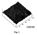
- Figure 1 shows a scanning electron microscopic image of the surface of a polymeric substrate (polyethylene terephthalate) shear coated with a layer of Compound A above.
- Coating of the liquid crystal materials can be preformed by any convenient means that provides for the ordered arrangement of the liquid crystals along the plane of the substrate onto which they are applied.
- coating methods that impart shear stress to the coating material during the coating process will be preferred since shear stress imparted during coating can serve to form large and uniform domains of the ordered lyotropic liquid crystal molecules.
- Coating techniques that impart such shear stresses include wire-wound rod coating and conventional extrusion dye coating.
- Drying of the coated liquid crystal layer can be performed using any means suitable for drying aqueous coatings. Useful drying methods will not damage the coating or significantly disrupt any molecular ordering of the coated layer imparted by shear stress or other ordering effects applied during coating or application.
- Substrates onto which the lyotropic materials can be applied include any solid material that will accept the coating of the liquid crystal material and that possesses whatever optical characteristics may be desired for its intended application. For example, transparency, translucency or reflectivity may be indicated for a given application.
- Suitable substrate materials include, for example, glass, rigid polymeric materials, flexible polymeric films, multilayer films and optical stacks.
- the substrates can also include any other layers customarily found in display devices or other components useful in displays. Such additional layers include, for example, polarizers, retarders, color filters, black matrices and electronically-addressable active or passive devices (e.g. , transparent electrodes, organic and inorganic light emitting devices and thin film transistors) and the like.
- useful substrates can include one or more optically active layers (such as polarizers, color filters, etc.) and/or one or more additional layers or materials that can be used to affect or control the transmission, reflection, or absorption of light through an overall display construction.
- Suitable substrate materials can be colored or clear and can be birefringent or non-birefringent.
- the alignment lyotropic liquid crystal materials can be coated or otherwise ordered onto substrates that have patterned electrodes (e.g. , transparent conductive oxide stripes such as indium tin oxide (“ITO")) and/or that have a matrix of thin film transistors (“TFTs”) or other electrically active devices.
- patterned electrodes e.g. , transparent conductive oxide stripes such as indium tin oxide (“ITO")
- TFTs thin film transistors
- Such embodiments would include coating or ordering of the lyotropic materials directly on top of such electrodes or TFTs, on top of one or more immediate layers such as one or more planarization layer, or on a surface of the substrate opposing the surface having the electrodes or TFTs.
- the lyotropic materials can be coated onto substrates that are later equipped with electrodes and/or active devices.
- Coating solutions of the lyotropic materials can be made by preparing a simple aqueous solution of water and a pH-adjusting compound such as NH 4 OH. The coating solution can then be prepared by dissolving the lyotropic material in aqueous solution along with other additives such as surfactants and one or more polarizing and/or filtering dyes. Suitable water-soluble polymeric binders can also be added in small amounts ranging from less than about 1 percent by weight to 5 percent or more to the solutions. Polymers found useful for this purpose include dextran-type polymers and their sulfates and sulfonated polystyrenes.
- the liquid crystal materials can be added in amounts sufficient to form a solution of the lyotropic material with a concentration in the range from about 8 to about 20 percent by weight of the solution, though concentrations in the range from about 10 to about 16 percent by weight often are more preferred. Solutions of the lyotropic material outside this concentration range can also be used provided a desired level of functionality is preserved. For example, a solution of the lyotropic material should provide sufficient levels of ordered material on the final substrate and should therefore be sufficiently concentrated to provide adequate coating thickness and dryability, but not so concentrated as to be prohibitively difficult to coat and/or orient.
- one or more color dyes directly into the alignment structure to provide polarizing and/or color filtration functions. Such incorporation can eliminate the need for additional, separate polarizers or color filter layers in an overall display construction.
- one or more pleochroic dyes can be incorporated into the ordered matrix of the lyotropic material to provide an ordered color polarizer.
- the incorporated dyes can be selected to provide a variety of useful filtration and polarizing optical effects in a display construction. Many such constructions are provided in co-pending U.S. Patent Application serial number 09/426,288.
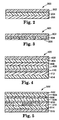
- FIG. 2 shows the construction of a simple liquid crystal cell 200 according to one embodiment of the invention.
- the liquid crystal cell 200 includes a top substrate 202 and a bottom substrate 206. On at least one surface of each substrate is an ordered layer of lyotropic liquid crystal material. Between the top and bottom alignment layers is a layer of aligned liquid crystal material 204.
- the aligned liquid crystal material could include any conventional nematic or smectic liquid crystal material, including twisted nematic liquid crystals, super twisted nematic liquid crystals, ferroelectric liquid crystals, anti-ferroelectric liquid crystals, cholesteric materials, etc.
- the aligned liquid crystal material can also constitute or include any of the chromonic materials or other lyotropic liquid crystal materials described above.
- top and bottom substrates are positioned such that the surface containing the ordered layer of lyotropic material of each of the substrates is in contact with the liquid crystal material 204 and are positioned to orient the liquid crystal material 204 in a desired manner.
- Either or both of the top and bottom substrates 202 and 206 can optionally include additional optically active layers.
- one or more pleochroic dyes are incorporated into the lyotropic liquid crystal material of the alignment layer in such a manner that, upon application to the alignment substrate, the pleochroic dye is oriented with the lyotropic liquid crystal and the resulting alignment substrate may also be used as a dichroic polarizer.
- Figure 3 shows one possible construction of an alignment structure according to the invention.
- a transparent electrode layer 304 such as indium tin oxide.
- Adjacent to the electrode layer 304 is an ordered layer of lyotropic liquid crystal material 306.
- the lyotropic material includes one or more pleochroic dyes and can thus function simultaneously, depending on the selection and orientation of the dye, as a polarizer, a color filter and an alignment layer.
- FIG. 4 provides a cross-sectional view of a possible two-polarizer liquid crystal display device, or LCD.
- the LCD 400 includes a top polarizer 402, an optional retarder or compensator 404, a liquid crystal cell that includes a top substrate 406, a bottom substrate 410 and a liquid crystal material 408 disposed therebetween.
- a bottom polarizer 412 below the liquid crystal cell is a bottom polarizer 412 and an optional reflective layer or transflector 414.
- At least one of the top and bottom substrates contains an ordered layer of the lyotropic liquid crystal material disposed along the surface that is in contact with the liquid crystal material 408.
- the reflective or transflector layer 414 can be provided to allow lighting of the liquid crystal display 400 using ambient light or light from a front light guide (not shown).
- a back light also not shown
- FIG. 5 provides a cross-section view of a possible configuration of a color liquid crystal display device that incorporates one or more of the alignment structures of the invention.
- the color liquid crystal display device 500 includes a top polarizer 502 and a bottom polarizer 516. Between the top and bottom polarizers is a liquid crystal cell that includes a top alignment layer comprising a top substrate material 504 on which is disposed an ordered layer or coating of a lyotropic liquid crystal material 506.
- a bottom substrate is made of another ordered layer or coating of lyotropic liquid crystal material 510, a color filter array 512 and a bottom substrate material 514. Disposed between the two substrates and in contact with the two adjacent ordered layers or coatings of lyotropic material is a liquid crystal material 508.
- full color displays employ a regular pattern of primary color filters for color the filter array 512.
- the color filters can be a regular array of three colors, typically red, green and blue, or cyan, magenta and yellow.
- the color filters can be colored polarizers.
- a chromonic material in zwitterionic form 4-( ⁇ 4-[(4-carboxylphenyl)amino]-6-[4-(dimethylamino)pyridinium-1-yl]-1,3,5-triazin-2-yl ⁇ amino)benzoate, was prepared in the following manner according to the following reaction.
- the solution was passed down a 600 mm by 58 mm column containing 300 g of Mitsubishi SAT-10 ion exchange resin (the resin was prewashed with a 0.5 wt % aqueous ammonium hydroxide solution).
- the eluent was stripped in vacuum at 15 mm Hg and 80 °C to give 12.66 g of 4-( ⁇ 4-[(4-carboxylphenyl)amino]-6-[4-(dimethylamino)pyridinium-1-yl]-1,3,5-triazin-2-yl ⁇ amino)benzoate.
- An aqueous solution of a chromonic compound (Compound A) was prepared having a concentration of between 8 and 10 percent by weight of solution.
- a thin layer of the chromonic solution was coated onto one side of each of two glass slides using a simple knife coater.
- the two glass slides were previously coated with a transparent conductive layer of indium tin oxide (700 ⁇ ).
- the slides were air dried, and glass beads 5g in diameter were sprayed from solution on the side of each slide coated with the chromonic layer.
- the slides were adhered together in such a manner that the coating directions of the chromonic layers were at 90° to one another and such that the two cells together formed a simple cell construction.
- a small opening was left between the slides, and the cell was vacuum filled with nematic liquid crystal material ZLI1565, available from Merck Inc.
- the filled cell was viewed under a microscope between two crossed polarizers.
- the filled cell transmitted substantially all light between the polarizers, indicating the achievement of a uniformly-aligned 90° twist of the nematic liquid crystal material within the cell.
Description


Claims (9)
- An alignment structure comprising a substrate having disposed thereon an oriented layer of a colorless non-polymeric lyotropic liquid crystal material.
- The alignment structure of claim 1 further comprising one or more additives.
- The alignment structure of claim I further comprising one or more pleochroic dyes.
- The alignment structure of claim 1 further comprising a transparent electrode layer.
- The alignment structure of claim 1 further comprising at least one color filter element or array.
- The alignment structure of claim 1 further comprising at least one additional layer in contact with the oriented layer of lyotropic liquid crystal material.
- An optical device comprising a liquid crystal material disposed between two parallel display panel substrates, at least one of the substrates having disposed thereon an oriented layer of a colorless non-polymeric lyotropic liquid crystal material.
- A method of making an alignment structure comprising coating a solution of a colorless non-polymeric lyotropic liquid crystal material onto a substrate and drying said coated material.
- An optical device comprising a liquid crystal material disposed on the alignment structure of one of claims 1 to 6.
Applications Claiming Priority (5)
| Application Number | Priority Date | Filing Date | Title |
|---|---|---|---|
| US43919099A | 1999-11-12 | 1999-11-12 | |
| US439190 | 1999-11-12 | ||
| US09/708,752 US6395354B1 (en) | 1999-11-12 | 2000-11-08 | Liquid crystal alignment structures and optical devices containing same |
| US708752 | 2000-11-08 | ||
| PCT/US2000/031181 WO2001035161A1 (en) | 1999-11-12 | 2000-11-09 | Liquid crystal alignment structures and optical devices containing same |
Publications (2)
| Publication Number | Publication Date |
|---|---|
| EP1232414A1 EP1232414A1 (en) | 2002-08-21 |
| EP1232414B1 true EP1232414B1 (en) | 2004-02-04 |
Family
ID=27031953
Family Applications (1)
| Application Number | Title | Priority Date | Filing Date |
|---|---|---|---|
| EP00980368A Expired - Lifetime EP1232414B1 (en) | 1999-11-12 | 2000-11-09 | Liquid crystal alignment structures, method of making the same, and optical devices containing the same |
Country Status (7)
| Country | Link |
|---|---|
| US (1) | US6524665B2 (en) |
| EP (1) | EP1232414B1 (en) |
| JP (1) | JP2003534563A (en) |
| CN (1) | CN1183412C (en) |
| AU (1) | AU1763701A (en) |
| DE (1) | DE60008137T2 (en) |
| WO (1) | WO2001035161A1 (en) |
Cited By (8)
| Publication number | Priority date | Publication date | Assignee | Title |
|---|---|---|---|---|
| US7582330B2 (en) | 2004-11-24 | 2009-09-01 | 3M Innovative Properties Counsel | Method for making metallic nanostructures |
| US7601769B2 (en) | 2005-12-19 | 2009-10-13 | 3M Innovative Peroperties Company | Multilayered chromonic structures |
| US7629027B2 (en) | 2005-10-14 | 2009-12-08 | 3M Innovative Properties Company | Method for making chromonic nanoparticles |
| US7687115B2 (en) | 2004-11-24 | 2010-03-30 | 3M Innovative Properties Company | Method for making nanostructured surfaces |
| US7718716B2 (en) | 2005-10-14 | 2010-05-18 | 3M Innovative Properties Company | Chromonic nanoparticles containing bioactive compounds |
| US7807661B2 (en) | 2005-12-08 | 2010-10-05 | 3M Innovative Properties Company | Silver ion releasing articles and methods of manufacture |
| US7824732B2 (en) | 2005-12-28 | 2010-11-02 | 3M Innovative Properties Company | Encapsulated chromonic particles |
| US8092710B2 (en) | 2005-12-19 | 2012-01-10 | 3M Innovative Properties Company | Hierarchical chromonic structures |
Families Citing this family (28)
| Publication number | Priority date | Publication date | Assignee | Title |
|---|---|---|---|---|
| US6171802B1 (en) * | 1998-06-10 | 2001-01-09 | Kent State University | Detection and amplification of ligands |
| US20020052002A1 (en) * | 1998-06-10 | 2002-05-02 | Niehaus Gary D. | Detection and amplification of ligands |
| US7550216B2 (en) * | 1999-03-03 | 2009-06-23 | Foster-Miller, Inc. | Composite solid polymer electrolyte membranes |
| US6488866B1 (en) | 2000-11-08 | 2002-12-03 | 3M Innovative Properties Company | Liquid crystal materials and alignment structures and optical devices containing same |
| US7632540B2 (en) * | 2003-07-01 | 2009-12-15 | Transitions Optical, Inc. | Alignment facilities for optical dyes |
| US7342112B2 (en) * | 2003-07-01 | 2008-03-11 | Ppg Industries Ohio, Inc. | Photochromic compounds |
| RU2006102188A (en) * | 2003-07-31 | 2006-07-10 | ЗМ Инновейтив Пропертиз Компани (US) | BIOACTIVE COMPOSITIONS INCLUDING TRIAZINES |
| JP2008500701A (en) * | 2004-05-22 | 2008-01-10 | フオスター・ミラー・インコーポレイテツド | Solid polymer electrolyte membrane |
| JP2006023730A (en) * | 2004-06-11 | 2006-01-26 | Dainippon Printing Co Ltd | Liquid crystal display element |
| US20060110540A1 (en) * | 2004-11-24 | 2006-05-25 | 3M Innovative Properties Company | Method for making nanostructured surfaces |
| US7247723B2 (en) | 2004-11-24 | 2007-07-24 | 3M Innovative Properties Company | Metallic chromonic compounds |
| US20070128291A1 (en) * | 2005-12-07 | 2007-06-07 | Tokie Jeffrey H | Method and Apparatus for Forming Chromonic Nanoparticles |
| JP4870436B2 (en) * | 2006-01-10 | 2012-02-08 | 株式会社 日立ディスプレイズ | Liquid crystal display |
| JP5015963B2 (en) * | 2006-01-26 | 2012-09-05 | スリーエム イノベイティブ プロパティズ カンパニー | Method for manufacturing nanostructures using chromonics |
| US20070275185A1 (en) * | 2006-05-23 | 2007-11-29 | 3M Innovative Properties Company | Method of making ordered nanostructured layers |
| JP4978995B2 (en) * | 2006-11-08 | 2012-07-18 | 株式会社ジャパンディスプレイイースト | Liquid crystal display |
| JP4760695B2 (en) * | 2006-12-13 | 2011-08-31 | 三菱化学株式会社 | Anisotropic film material, anisotropic film composition, anisotropic film and optical element |
| CN101311777B (en) * | 2007-05-24 | 2011-05-04 | 台湾薄膜电晶体液晶显示器产业协会 | Light emitting -type optical film and process for manufacture thereof, and LCD device |
| US7718219B2 (en) | 2007-06-27 | 2010-05-18 | 3M Innovative Properties Company | Method for forming channel patterns with chromonic materials |
| JP2009080224A (en) * | 2007-09-26 | 2009-04-16 | Nitto Denko Corp | Method for manufacturing coating liquid and optically anisotropic film |
| JP2011511953A (en) * | 2007-12-14 | 2011-04-14 | スリーエム イノベイティブ プロパティズ カンパニー | Electronic device manufacturing method |
| EP2398435A4 (en) | 2009-02-17 | 2015-05-06 | 3M Innovative Properties Co | Optical control devices and methods of making |
| WO2011140012A1 (en) | 2010-05-05 | 2011-11-10 | 3M Innovative Properties Company | Optical shutter applicable in stereoscopic viewing glasses |
| US8941795B2 (en) | 2011-12-20 | 2015-01-27 | Apple Inc. | Electronic device with backlit display |
| JP6001874B2 (en) * | 2012-02-17 | 2016-10-05 | 日東電工株式会社 | OPTICAL LAMINATE AND METHOD FOR PRODUCING OPTICAL LAMINATE |
| CN103676331B (en) | 2013-12-27 | 2017-01-04 | 京东方科技集团股份有限公司 | A kind of conduction oriented layer and preparation method, display base plate, display device |
| JP2015128036A (en) * | 2013-12-30 | 2015-07-09 | 日本写真印刷株式会社 | Transparent conductive sheet and touch panel using transparent conductive sheet |
| KR102296012B1 (en) * | 2018-02-15 | 2021-08-30 | 후지필름 가부시키가이샤 | Binder composition, binder layer, optical laminate and image display device |
Family Cites Families (21)
| Publication number | Priority date | Publication date | Assignee | Title |
|---|---|---|---|---|
| DE285103C (en) | ||||
| US4165923A (en) | 1972-04-10 | 1979-08-28 | Ncr Corporation | Liquid crystal alignment structure |
| US4031092A (en) * | 1975-06-16 | 1977-06-21 | Minnesota Mining And Manufacturing Company | 1,3-Bis-(carboxy-phenylamino)-s-triazines |
| US4767191A (en) | 1986-11-14 | 1988-08-30 | U.S. Philips Corporation | Display cell |
| US4776215A (en) | 1987-04-30 | 1988-10-11 | Dynabal Corporation | Dynamic balancing system and method |
| DD285103A5 (en) * | 1989-06-26 | 1990-12-05 | Martin-Luther-Universitaet Halle Wittenberg,Dd | AMPHOTROPE LIQUID CRYSTALLINE AMPHIPHILE |
| JP2938124B2 (en) * | 1990-04-05 | 1999-08-23 | オプトレックス株式会社 | Method for forming alignment film and method for manufacturing liquid crystal display element |
| DE69215565T2 (en) | 1991-03-26 | 1997-05-28 | Philips Electronics Nv | Liquid crystal image display device with orientation layer |
| JPH05265004A (en) | 1992-03-23 | 1993-10-15 | Kanegafuchi Chem Ind Co Ltd | Liquid crystal oriented film and liquid crystal element formed by using this film |
| JP3288131B2 (en) | 1992-06-02 | 2002-06-04 | 株式会社日立製作所 | Data recording / reproducing device |
| RU2047643C1 (en) | 1993-05-21 | 1995-11-10 | Хан Ир Гвон | Material for polarizing coating |
| JP2693368B2 (en) | 1993-06-29 | 1997-12-24 | スタンレー電気株式会社 | Liquid crystal display device and method of manufacturing the same |
| KR0148391B1 (en) | 1993-08-31 | 1998-11-16 | 박경팔 | Lcd element |
| KR0178418B1 (en) | 1994-05-31 | 1999-05-01 | 윤종용 | Manufacturing method of liquid crystal panel |
| KR0140819B1 (en) * | 1994-07-06 | 1998-06-15 | 강박광 | Conductive liquid crystal alignment layer and process thereof |
| AU4405996A (en) | 1994-11-18 | 1996-06-17 | Russian Technology Group | Dichroic light polarizers |
| JPH08165360A (en) * | 1994-12-16 | 1996-06-25 | Hitachi Ltd | Production of conductive oriented polymer film, and conductive oriented polymer film |
| KR960024579A (en) | 1994-12-26 | 1996-07-20 | 윤종용 | Method of forming alignment film of liquid crystal display device |
| JPH10186363A (en) | 1996-12-27 | 1998-07-14 | Sharp Corp | Manufacturing device for liquid crystal oriented film |
| US5948487A (en) * | 1997-09-05 | 1999-09-07 | 3M Innovative Properties Company | Anisotropic retardation layers for display devices |
| AU3887100A (en) * | 1999-11-12 | 2001-05-30 | 3M Innovative Properties Company | Liquid crystal alignment structure and display devices containing same |
-
2000
- 2000-11-09 WO PCT/US2000/031181 patent/WO2001035161A1/en active IP Right Grant
- 2000-11-09 AU AU17637/01A patent/AU1763701A/en not_active Abandoned
- 2000-11-09 JP JP2001536634A patent/JP2003534563A/en not_active Withdrawn
- 2000-11-09 CN CNB008183708A patent/CN1183412C/en not_active Expired - Fee Related
- 2000-11-09 DE DE60008137T patent/DE60008137T2/en not_active Expired - Fee Related
- 2000-11-09 EP EP00980368A patent/EP1232414B1/en not_active Expired - Lifetime
-
2002
- 2002-04-25 US US10/132,774 patent/US6524665B2/en not_active Expired - Fee Related
Cited By (10)
| Publication number | Priority date | Publication date | Assignee | Title |
|---|---|---|---|---|
| US7582330B2 (en) | 2004-11-24 | 2009-09-01 | 3M Innovative Properties Counsel | Method for making metallic nanostructures |
| US7687115B2 (en) | 2004-11-24 | 2010-03-30 | 3M Innovative Properties Company | Method for making nanostructured surfaces |
| US7629027B2 (en) | 2005-10-14 | 2009-12-08 | 3M Innovative Properties Company | Method for making chromonic nanoparticles |
| US7718716B2 (en) | 2005-10-14 | 2010-05-18 | 3M Innovative Properties Company | Chromonic nanoparticles containing bioactive compounds |
| US7807661B2 (en) | 2005-12-08 | 2010-10-05 | 3M Innovative Properties Company | Silver ion releasing articles and methods of manufacture |
| US7601769B2 (en) | 2005-12-19 | 2009-10-13 | 3M Innovative Peroperties Company | Multilayered chromonic structures |
| US7993748B2 (en) | 2005-12-19 | 2011-08-09 | 3M Innovative Properties Company | Multilayered chromonic structures |
| US8092710B2 (en) | 2005-12-19 | 2012-01-10 | 3M Innovative Properties Company | Hierarchical chromonic structures |
| US7824732B2 (en) | 2005-12-28 | 2010-11-02 | 3M Innovative Properties Company | Encapsulated chromonic particles |
| US7981469B2 (en) | 2005-12-28 | 2011-07-19 | 3M Innovative Properites Company | Encapsulated chromonic particles |
Also Published As
| Publication number | Publication date |
|---|---|
| JP2003534563A (en) | 2003-11-18 |
| CN1183412C (en) | 2005-01-05 |
| WO2001035161A1 (en) | 2001-05-17 |
| AU1763701A (en) | 2001-06-06 |
| US20020132065A1 (en) | 2002-09-19 |
| DE60008137T2 (en) | 2004-09-16 |
| US6524665B2 (en) | 2003-02-25 |
| EP1232414A1 (en) | 2002-08-21 |
| CN1423759A (en) | 2003-06-11 |
| DE60008137D1 (en) | 2004-03-11 |
Similar Documents
| Publication | Publication Date | Title |
|---|---|---|
| EP1232414B1 (en) | Liquid crystal alignment structures, method of making the same, and optical devices containing the same | |
| US6645578B2 (en) | Liquid crystal materials and alignment structures and optical devices containing same | |
| US6395354B1 (en) | Liquid crystal alignment structures and optical devices containing same | |
| US6699533B2 (en) | Stabilized liquid crystal alignment structure with pre-tilt angle and display devices containing the same | |
| EP1003821B1 (en) | Anisotropic retardation layers for display devices | |
| US8865895B2 (en) | Organic compound, anisotropic optical film and method of production thereof | |
| KR100960844B1 (en) | In-Cell TYPE POLARIZER COMPOSITION, In-Cell TYPE POLARIZER, In-Cell TYPE LAYERED LIGHT POLARIZER, AND LIQUID CRYSTAL ELEMENT USING THE SAME | |
| WO2008142635A2 (en) | Compensated in-plane switching mode liquid crystal display | |
| US20130038803A1 (en) | Optical shutter applicable in stereoscopic viewing glasses | |
| JP2916791B2 (en) | Liquid crystal display device | |
| JPH0519231A (en) | Stn type liquid crystal display device |
Legal Events
| Date | Code | Title | Description |
|---|---|---|---|
| PUAI | Public reference made under article 153(3) epc to a published international application that has entered the european phase |
Free format text: ORIGINAL CODE: 0009012 |
|
| 17P | Request for examination filed |
Effective date: 20020612 |
|
| AK | Designated contracting states |
Kind code of ref document: A1 Designated state(s): AT BE CH CY DE DK ES FI FR GB GR IE IT LI LU MC NL PT SE TR |
|
| AX | Request for extension of the european patent |
Free format text: AL;LT;LV;MK;RO;SI |
|
| GRAH | Despatch of communication of intention to grant a patent |
Free format text: ORIGINAL CODE: EPIDOS IGRA |
|
| RTI1 | Title (correction) |
Free format text: LIQUID CRYSTAL ALIGNMENT STRUCTURES, METHOD OF MAKING THE SAME, AND OPTICAL DEVICES CONTAINING THE SAME |
|
| GRAH | Despatch of communication of intention to grant a patent |
Free format text: ORIGINAL CODE: EPIDOS IGRA |
|
| GRAA | (expected) grant |
Free format text: ORIGINAL CODE: 0009210 |
|
| AK | Designated contracting states |
Kind code of ref document: B1 Designated state(s): DE GB |
|
| REG | Reference to a national code |
Ref country code: GB Ref legal event code: FG4D |
|
| REF | Corresponds to: |
Ref document number: 60008137 Country of ref document: DE Date of ref document: 20040311 Kind code of ref document: P |
|
| LTIE | Lt: invalidation of european patent or patent extension |
Effective date: 20040204 |
|
| PLBE | No opposition filed within time limit |
Free format text: ORIGINAL CODE: 0009261 |
|
| STAA | Information on the status of an ep patent application or granted ep patent |
Free format text: STATUS: NO OPPOSITION FILED WITHIN TIME LIMIT |
|
| 26N | No opposition filed |
Effective date: 20041105 |
|
| PGFP | Annual fee paid to national office [announced via postgrant information from national office to epo] |
Ref country code: GB Payment date: 20071128 Year of fee payment: 8 |
|
| PGFP | Annual fee paid to national office [announced via postgrant information from national office to epo] |
Ref country code: DE Payment date: 20071221 Year of fee payment: 8 |
|
| GBPC | Gb: european patent ceased through non-payment of renewal fee |
Effective date: 20081109 |
|
| PG25 | Lapsed in a contracting state [announced via postgrant information from national office to epo] |
Ref country code: DE Free format text: LAPSE BECAUSE OF NON-PAYMENT OF DUE FEES Effective date: 20090603 |
|
| PG25 | Lapsed in a contracting state [announced via postgrant information from national office to epo] |
Ref country code: GB Free format text: LAPSE BECAUSE OF NON-PAYMENT OF DUE FEES Effective date: 20081109 |