EP1231589A1 - Stereoscopic plasma display - Google Patents
Stereoscopic plasma display Download PDFInfo
- Publication number
- EP1231589A1 EP1231589A1 EP01103185A EP01103185A EP1231589A1 EP 1231589 A1 EP1231589 A1 EP 1231589A1 EP 01103185 A EP01103185 A EP 01103185A EP 01103185 A EP01103185 A EP 01103185A EP 1231589 A1 EP1231589 A1 EP 1231589A1
- Authority
- EP
- European Patent Office
- Prior art keywords
- sub
- fields
- picture
- field
- common
- Prior art date
- Legal status (The legal status is an assumption and is not a legal conclusion. Google has not performed a legal analysis and makes no representation as to the accuracy of the status listed.)
- Granted
Links
Images


Classifications
-
- H—ELECTRICITY
- H04—ELECTRIC COMMUNICATION TECHNIQUE
- H04N—PICTORIAL COMMUNICATION, e.g. TELEVISION
- H04N13/00—Stereoscopic video systems; Multi-view video systems; Details thereof
- H04N13/20—Image signal generators
- H04N13/204—Image signal generators using stereoscopic image cameras
- H04N13/239—Image signal generators using stereoscopic image cameras using two 2D image sensors having a relative position equal to or related to the interocular distance
-
- G—PHYSICS
- G09—EDUCATION; CRYPTOGRAPHY; DISPLAY; ADVERTISING; SEALS
- G09G—ARRANGEMENTS OR CIRCUITS FOR CONTROL OF INDICATING DEVICES USING STATIC MEANS TO PRESENT VARIABLE INFORMATION
- G09G3/00—Control arrangements or circuits, of interest only in connection with visual indicators other than cathode-ray tubes
- G09G3/20—Control arrangements or circuits, of interest only in connection with visual indicators other than cathode-ray tubes for presentation of an assembly of a number of characters, e.g. a page, by composing the assembly by combination of individual elements arranged in a matrix no fixed position being assigned to or needed to be assigned to the individual characters or partial characters
- G09G3/2007—Display of intermediate tones
- G09G3/2018—Display of intermediate tones by time modulation using two or more time intervals
- G09G3/2022—Display of intermediate tones by time modulation using two or more time intervals using sub-frames
- G09G3/2029—Display of intermediate tones by time modulation using two or more time intervals using sub-frames the sub-frames having non-binary weights
-
- G—PHYSICS
- G09—EDUCATION; CRYPTOGRAPHY; DISPLAY; ADVERTISING; SEALS
- G09G—ARRANGEMENTS OR CIRCUITS FOR CONTROL OF INDICATING DEVICES USING STATIC MEANS TO PRESENT VARIABLE INFORMATION
- G09G3/00—Control arrangements or circuits, of interest only in connection with visual indicators other than cathode-ray tubes
- G09G3/001—Control arrangements or circuits, of interest only in connection with visual indicators other than cathode-ray tubes using specific devices not provided for in groups G09G3/02 - G09G3/36, e.g. using an intermediate record carrier such as a film slide; Projection systems; Display of non-alphanumerical information, solely or in combination with alphanumerical information, e.g. digital display on projected diapositive as background
- G09G3/003—Control arrangements or circuits, of interest only in connection with visual indicators other than cathode-ray tubes using specific devices not provided for in groups G09G3/02 - G09G3/36, e.g. using an intermediate record carrier such as a film slide; Projection systems; Display of non-alphanumerical information, solely or in combination with alphanumerical information, e.g. digital display on projected diapositive as background to produce spatial visual effects
-
- G—PHYSICS
- G09—EDUCATION; CRYPTOGRAPHY; DISPLAY; ADVERTISING; SEALS
- G09G—ARRANGEMENTS OR CIRCUITS FOR CONTROL OF INDICATING DEVICES USING STATIC MEANS TO PRESENT VARIABLE INFORMATION
- G09G3/00—Control arrangements or circuits, of interest only in connection with visual indicators other than cathode-ray tubes
- G09G3/20—Control arrangements or circuits, of interest only in connection with visual indicators other than cathode-ray tubes for presentation of an assembly of a number of characters, e.g. a page, by composing the assembly by combination of individual elements arranged in a matrix no fixed position being assigned to or needed to be assigned to the individual characters or partial characters
- G09G3/22—Control arrangements or circuits, of interest only in connection with visual indicators other than cathode-ray tubes for presentation of an assembly of a number of characters, e.g. a page, by composing the assembly by combination of individual elements arranged in a matrix no fixed position being assigned to or needed to be assigned to the individual characters or partial characters using controlled light sources
- G09G3/28—Control arrangements or circuits, of interest only in connection with visual indicators other than cathode-ray tubes for presentation of an assembly of a number of characters, e.g. a page, by composing the assembly by combination of individual elements arranged in a matrix no fixed position being assigned to or needed to be assigned to the individual characters or partial characters using controlled light sources using luminous gas-discharge panels, e.g. plasma panels
- G09G3/2803—Display of gradations
-
- G—PHYSICS
- G09—EDUCATION; CRYPTOGRAPHY; DISPLAY; ADVERTISING; SEALS
- G09G—ARRANGEMENTS OR CIRCUITS FOR CONTROL OF INDICATING DEVICES USING STATIC MEANS TO PRESENT VARIABLE INFORMATION
- G09G3/00—Control arrangements or circuits, of interest only in connection with visual indicators other than cathode-ray tubes
- G09G3/20—Control arrangements or circuits, of interest only in connection with visual indicators other than cathode-ray tubes for presentation of an assembly of a number of characters, e.g. a page, by composing the assembly by combination of individual elements arranged in a matrix no fixed position being assigned to or needed to be assigned to the individual characters or partial characters
- G09G3/22—Control arrangements or circuits, of interest only in connection with visual indicators other than cathode-ray tubes for presentation of an assembly of a number of characters, e.g. a page, by composing the assembly by combination of individual elements arranged in a matrix no fixed position being assigned to or needed to be assigned to the individual characters or partial characters using controlled light sources
- G09G3/28—Control arrangements or circuits, of interest only in connection with visual indicators other than cathode-ray tubes for presentation of an assembly of a number of characters, e.g. a page, by composing the assembly by combination of individual elements arranged in a matrix no fixed position being assigned to or needed to be assigned to the individual characters or partial characters using controlled light sources using luminous gas-discharge panels, e.g. plasma panels
- G09G3/288—Control arrangements or circuits, of interest only in connection with visual indicators other than cathode-ray tubes for presentation of an assembly of a number of characters, e.g. a page, by composing the assembly by combination of individual elements arranged in a matrix no fixed position being assigned to or needed to be assigned to the individual characters or partial characters using controlled light sources using luminous gas-discharge panels, e.g. plasma panels using AC panels
- G09G3/291—Control arrangements or circuits, of interest only in connection with visual indicators other than cathode-ray tubes for presentation of an assembly of a number of characters, e.g. a page, by composing the assembly by combination of individual elements arranged in a matrix no fixed position being assigned to or needed to be assigned to the individual characters or partial characters using controlled light sources using luminous gas-discharge panels, e.g. plasma panels using AC panels controlling the gas discharge to control a cell condition, e.g. by means of specific pulse shapes
- G09G3/294—Control arrangements or circuits, of interest only in connection with visual indicators other than cathode-ray tubes for presentation of an assembly of a number of characters, e.g. a page, by composing the assembly by combination of individual elements arranged in a matrix no fixed position being assigned to or needed to be assigned to the individual characters or partial characters using controlled light sources using luminous gas-discharge panels, e.g. plasma panels using AC panels controlling the gas discharge to control a cell condition, e.g. by means of specific pulse shapes for lighting or sustain discharge
-
- H—ELECTRICITY
- H04—ELECTRIC COMMUNICATION TECHNIQUE
- H04N—PICTORIAL COMMUNICATION, e.g. TELEVISION
- H04N13/00—Stereoscopic video systems; Multi-view video systems; Details thereof
- H04N13/10—Processing, recording or transmission of stereoscopic or multi-view image signals
- H04N13/106—Processing image signals
- H04N13/139—Format conversion, e.g. of frame-rate or size
-
- H—ELECTRICITY
- H04—ELECTRIC COMMUNICATION TECHNIQUE
- H04N—PICTORIAL COMMUNICATION, e.g. TELEVISION
- H04N13/00—Stereoscopic video systems; Multi-view video systems; Details thereof
- H04N13/10—Processing, recording or transmission of stereoscopic or multi-view image signals
- H04N13/106—Processing image signals
- H04N13/161—Encoding, multiplexing or demultiplexing different image signal components
-
- H—ELECTRICITY
- H04—ELECTRIC COMMUNICATION TECHNIQUE
- H04N—PICTORIAL COMMUNICATION, e.g. TELEVISION
- H04N13/00—Stereoscopic video systems; Multi-view video systems; Details thereof
- H04N13/10—Processing, recording or transmission of stereoscopic or multi-view image signals
- H04N13/106—Processing image signals
- H04N13/167—Synchronising or controlling image signals
-
- H—ELECTRICITY
- H04—ELECTRIC COMMUNICATION TECHNIQUE
- H04N—PICTORIAL COMMUNICATION, e.g. TELEVISION
- H04N13/00—Stereoscopic video systems; Multi-view video systems; Details thereof
- H04N13/30—Image reproducers
- H04N13/332—Displays for viewing with the aid of special glasses or head-mounted displays [HMD]
- H04N13/341—Displays for viewing with the aid of special glasses or head-mounted displays [HMD] using temporal multiplexing
-
- H—ELECTRICITY
- H04—ELECTRIC COMMUNICATION TECHNIQUE
- H04N—PICTORIAL COMMUNICATION, e.g. TELEVISION
- H04N13/00—Stereoscopic video systems; Multi-view video systems; Details thereof
- H04N13/30—Image reproducers
- H04N13/356—Image reproducers having separate monoscopic and stereoscopic modes
-
- H—ELECTRICITY
- H04—ELECTRIC COMMUNICATION TECHNIQUE
- H04N—PICTORIAL COMMUNICATION, e.g. TELEVISION
- H04N13/00—Stereoscopic video systems; Multi-view video systems; Details thereof
- H04N13/30—Image reproducers
- H04N13/398—Synchronisation thereof; Control thereof
-
- G—PHYSICS
- G09—EDUCATION; CRYPTOGRAPHY; DISPLAY; ADVERTISING; SEALS
- G09G—ARRANGEMENTS OR CIRCUITS FOR CONTROL OF INDICATING DEVICES USING STATIC MEANS TO PRESENT VARIABLE INFORMATION
- G09G2310/00—Command of the display device
- G09G2310/02—Addressing, scanning or driving the display screen or processing steps related thereto
- G09G2310/0202—Addressing of scan or signal lines
- G09G2310/0205—Simultaneous scanning of several lines in flat panels
-
- G—PHYSICS
- G09—EDUCATION; CRYPTOGRAPHY; DISPLAY; ADVERTISING; SEALS
- G09G—ARRANGEMENTS OR CIRCUITS FOR CONTROL OF INDICATING DEVICES USING STATIC MEANS TO PRESENT VARIABLE INFORMATION
- G09G2320/00—Control of display operating conditions
- G09G2320/02—Improving the quality of display appearance
- G09G2320/0261—Improving the quality of display appearance in the context of movement of objects on the screen or movement of the observer relative to the screen
-
- H—ELECTRICITY
- H04—ELECTRIC COMMUNICATION TECHNIQUE
- H04N—PICTORIAL COMMUNICATION, e.g. TELEVISION
- H04N13/00—Stereoscopic video systems; Multi-view video systems; Details thereof
- H04N13/10—Processing, recording or transmission of stereoscopic or multi-view image signals
- H04N13/194—Transmission of image signals
-
- H—ELECTRICITY
- H04—ELECTRIC COMMUNICATION TECHNIQUE
- H04N—PICTORIAL COMMUNICATION, e.g. TELEVISION
- H04N13/00—Stereoscopic video systems; Multi-view video systems; Details thereof
- H04N13/20—Image signal generators
- H04N13/286—Image signal generators having separate monoscopic and stereoscopic modes
-
- H—ELECTRICITY
- H04—ELECTRIC COMMUNICATION TECHNIQUE
- H04N—PICTORIAL COMMUNICATION, e.g. TELEVISION
- H04N13/00—Stereoscopic video systems; Multi-view video systems; Details thereof
- H04N13/30—Image reproducers
- H04N13/332—Displays for viewing with the aid of special glasses or head-mounted displays [HMD]
- H04N13/334—Displays for viewing with the aid of special glasses or head-mounted displays [HMD] using spectral multiplexing
-
- H—ELECTRICITY
- H04—ELECTRIC COMMUNICATION TECHNIQUE
- H04N—PICTORIAL COMMUNICATION, e.g. TELEVISION
- H04N19/00—Methods or arrangements for coding, decoding, compressing or decompressing digital video signals
- H04N19/50—Methods or arrangements for coding, decoding, compressing or decompressing digital video signals using predictive coding
- H04N19/597—Methods or arrangements for coding, decoding, compressing or decompressing digital video signals using predictive coding specially adapted for multi-view video sequence encoding
Definitions
- the present invention relates to a method and device for processing stereoscopic video pictures. Particularly, the present invention relates to stereoscopic display of pictures on a plasma display panel (PDP).
- PDP plasma display panel
- Plasma technology allows achieving flat displays with large size, very limited depth and without relevant viewing angle constraints. For these reasons, the PDPs are really suitable for use in stereoscopic vision. This display causes no geometric distortion in the displayed image and therefore enables a precise depth impression of stereoscopic images. In addition, the big size of such a display suits very well to a strong impression of volume.
- the 3D perception from the Human Visual System is based on the close side-by-side positioning of the eyes. Each eye takes a view of the same area from a slightly different angle. These two separate images are sent to the brain for processing according to Fig. 1. When the two images arrive simultaneously in the back of the brain, they are united into one picture. The mind combines the two images by matching up the similarities and adding the small differences to catch finally a three-dimensional stereo picture. With stereo vision, the HVS sees an object as solid in three spatial dimensions (width, height and depth) and it is the added perception of the depth dimension that make stereo vision so rich and special. Moreover, a stereo picture will increase the impression of sharpness in the brain.
- 3D images are generated with the help of two video cameras positioned side-by-side in a similar way as the human eyes.
- Other methods mainly based on complex software are also able to generate artificial stereo pictures by ray tracing (simulation of light propagation).
- these images are called, left and right images.
- the principle of stereoscopic broadcasting is based on the transmission of the both images. This global concept is shown on Fig 2. If right and left images are displayed sequentially from a source, and a synchronized shutter system in front of the eye allows the right image to only enter the right eye and the left image to only enter the left eye, then the stereo vision can be observed as shown in Fig. 3.
- the shutter can be mounted in glasses which are matched with a display in which two constituent pictures are presented in alternation instead of simultaneously.
- the glasses occlude one eye and then the other in synchronism with the image displaying.
- This method is often called "field sequential". This method avoids the retinal rivalry caused by anaglyph viewing (other method based on a two-color glasses associated with a two-color picture - each color related to one eye and resulting in a monochrome stereoscopic vision, very old method traced back to 1858). Nevertheless, this method can introduce other discomfort such as the introduction of time parallax between the two images, or the possibility of "ghosting" between the image due to phosphor persistence.
- Most glasses-shutter systems use LCDs which function with polarized light. Currently, glasses using LCDs can provide good switching speed and reasonable extinction of the alternative lenses.
- the electro-optical polarizing shutter available on the market today transmit only 30% of the unpolarized input light (rather than 50% for perfect polarizers) and this reduces a lot the image brightness.
- Some eyeglass shutters are connected by wires to the monitor, others are controlled by infrared and are wireless.
- the displaying of stereo pictures on a Plasma screen needs also the possibility to display two different pictures per frame which is a new challenge for this technology.
- a PDP utilizes a matrix array of discharge cells which can only be “ON” or “OFF”. Also unlike a CRT or LCD in which gray levels are expressed by analog control of the light emission, a PDP controls the gray level by modulating the number of light pulses per frame (sustain pulses). This time-modulation will be integrated by the eye over a period corresponding to the eye time response. To perform a grayscale rendition, the Plasma display is commonly divided in sub-lighting periods called sub-fields each one corresponding to a bit of the input video picture data. For instance, if 8 bit luminance levels are provided, in that case each level will be represented by a combination of the 8 following bits : 1 - 2- 4 - 8 - 16 - 32 - 64 - 128 .
- the frame period will be divided in 8 lighting periods (called sub-fields), each one corresponding to a bit.
- the number of light pulses for the bit "2" is the double as for the bit "1", and so forth.
- a simple method to implement a stereoscopic displaying on a PDP is based on the separation of sub-fields into Left(L) and Right(R) groups which are synchronized with the open and close of the LCD shutter glasses. It is a further advantage of this method that with the same display 2D and 3D pictures can easily be generated by a simple change of the sub-field encoding process.
- Figure 4 shows a light emission scheme which has eighteen sub-fields per frame in 60Hz mode (16.7 ms). Nine sub-fields are assigned to each of the left and right images, for example.
- the object of the present invention to provide a method and device for processing stereoscopic video-pictures, wherein the loss of luminance is reduced.
- the main idea of the present invention is that the displaying is based on three fields instead of two. With this measure there is much more flexibility for distributing light to the left and right eye. In one field there are sub-fields grouped together which are used for producing light pulses dedicated exclusively for the left eye. In another field there are sub-fields grouped together which are used for producing light pulses dedicated exclusively for the right eye. In a further field there are grouped together some sub-fields which are used for producing light pulses dedicated for both eyes in common.
- This algorithm starts from the original left and right input pictures and makes the calculation of the specific left and right picture and the common picture in a different way namely under consideration of which sub-fields are available for the common picture, and the specific left and right picture.
- the algorithm makes a sub-field encoding for a pair of corresponding pixels from the original left and right picture, simultaneously. First, it performs a standard encoding for the greater pixel and then it checks whether the found code word entries for the common sub-fields can also be used for the smaller pixel. If not, the coding of the smaller pixel determines the entries for the common sub-fields and the coding of the greater pixel is revised. By this it is assured that the coding errors due to the reduced number of sub-fields being available for a single one of the three pictures are reduced.
- Fig. 5 shows the separation of the two original stereo-pictures L and R in three pictures L',C',R' which will be encoded separately and displayed.
- Fig. 6 shows an example based on the displaying of the three pictures R', L' and C' in three packages of six sub-fields.
- the shutter for the left eye is open for the first to twelfths sub-field and the shutter for the right eye is open for the sevenths to the eighteenths sub-field. So there is a common opening period during the sevenths to twelfths sub-field.
- the left eye will see a combination of the pictures L' and C' and the right eye will see a combination of the pictures C' and R'.
- the two pictures L and R have a lot of similarities.
- a similar concept can be implemented here.
- the pixels are encoded with the same code on the common sub-fields (similarity) and coding differences are allowed only in the specific sub-fields. Since the two pictures are related to the right and left eye, this principle is called Bit-Eye-Repeat.
- This concept can be utilized in the conventional stereoscopic plasma-displaying concept with two fields for the stereoscopic picture as well as with the basic idea of the use of three fields for the stereoscopic picture with three groups of sub-fields.
- the principle will be explained with the last stereoscopic displaying concept:
- a first odd weight (basic value B) has to be chosen which will represent the tolerance in the encoding of two near video values (maximal error). In the example this value is 5 (tolerance is 2).
- the other weights are chosen in order to be able to code all multiples of the basic value up to the maximum value, i.e. sum value.
- the displaying of such a code is shown Fig. 7; and, furthermore, Fig. 7 shows the behaviour of the shutter glasses in case of BER which are totally open during the displaying of the common sub-fields.
- a possible mixing in the case of the BER can be made as following: 1 - 2 - 4 - 5 - 5 - 8 - 10 - 10 - 15 - 20 - 20 - 30 - 40 - 40 - 50 - 50 - 70 - 70
- the bold sub-fields are related to the left eye
- the italic sub-fields are related to the right eye
- the underlined sub-fields are related to the common sub-fields. All these sub-fields are mixed together. Obviously, this can be also performed on the standard "sequential-field" method without the use of a common part.
- the sub-fields organization can be changed from one frame to another in order to increase this artifact reduction.
- Fig. 8 illustrates the principle of time parallax reduction by sub-field interleaving. It shows the interleaving of the different sub-fields for each Right, Left and Common sub-field group.
- the described displaying protocol will lead to a reduction of the time-parallax artifacts but this will need a good synchronization of the open and close states for each eyeglass with the lighting period of each sub-field.
- the switching frequency of the glasses is higher and optimal glasses have to be found to avoid a strong loss of picture luminance performance.
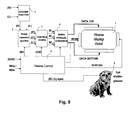
- Fig. 9 describes a possible circuit implementation of the picture separation algorithm described above.
- Input Right (R) and Left (L) pictures are forwarded to a degamma function block 1.
- the output of this block 1 is forwarded to a picture separation algorithm 2 which generates three pictures L', C' and R' which are forwarded sent to a sub-field encoder 3 to obtain three groups of sub-fields SF (R') , SF (C') and SF (L') .
- a plasma control unit 4 depending on the defined mode (2D or 3D activated, 50Hz or 60Hz mode) activates or deactivates the picture separation algorithm 2 with a signal SEL and selects the correct sub-fields encoding algorithm with a signal COD.
- This block generates all the plasma control signals priming, scan, sustain and erase and, furthermore, it generates all needed synchronization signals for the shutter eyeglasses 5.
- the codes for sub-fields SF (R') , SF (L') and SF (C') are input one after the other to a signal-parallel conversion unit 6, where the signals DATA TOP and DATA BOTTOM are generated for the top and bottom drivers of a plasma display panel 7.
- Fig. 10 describes a possible circuit implementation of the BER algorithm also described above.
- Input Right (R) and Left (L) pictures are forwarded to the degamma function block 1.
- the output of this block 1 is forwarded to the sub-field encoder 8 to obtain three groups of sub-fields SF(R'), SF(C') and SF(L').
- This sub-fields encoder 8 also contains the BER algorithm part.
- the plasma control 4 depending on the defined mode (2D or 3D activated, 50Hz or 60Hz mode) activates or deactivates the BER algorithm with the signal SEL and selects the correct sub-fields encoding algorithm with the signal COD.
- This block 4 also generates all the plasma control signals and, furthermore, it generates all needed synchronisation signals for the shutter eyeglasses 5. Further units correspond to those of Fig. 9.
- the advantages of present inventions are that the panel luminance in case of 3D stereoscopic displaying is improved, time parallax artifacts in case of stereoscopic displaying are reduced and the presented algorithms are very simple and therefore they do not request too much resources on chip (memory, computations%) . Only a slight adaptation of the plasma driving electronic should be necessary.
- the principles of the present invention are applicable to each kind of display dedicated to stereoscopic displaying and using a similar way of grey level rendition method like DMD, LCOS, ...
Abstract
Description
1 - 2- 4 - 8 - 16 - 32 - 64 - 128.
For each pixel of the screen:
C' = f (R, L), i.e. a function of the video values R and L and particularly the minimum thereof. Further it is defined:

SPEmax = 195 and B = 5.
- 1. (L) = 52 and (R) = 128
- 1 ○ Vmax=128 and Vmin=52.
- 2 ○ Vmax'=127 and Vmin'=52 with a difference D=(Vmax'-Vmin') =75=5x15.
- 3 ○Nothing to do since Vmax'-Vmin'=75 ≤ 195 (SPEmax).
- 4 ○127 = 1 + 2 + 4 + 5 + 10 + 15 + 20 + 30 + 40
- 5 ○COM_PART = 1 + 2 + 4 + 15 + 30 = 52. In this example, COMP_PART (52) ≤ Vmin'(52)
- 6 ○Encoding of all values:
-

-
1 - 2 - 4 - 5 - 5 - 8 - 10 - 10 - 15 - 20 - 20 - 30 - 40 - 40 - 50 - 50 - 70 - 70
Claims (13)
- Method for processing stereoscopic video pictures for stereoscopic display on a display device having a plurality of luminous elements, one or more of them corresponding to each of the pixels of a video picture, wherein each stereoscopic video picture includes an original left picture (L) and an original right picture (R), characterized by converting the original left picture (L) and the corresponding right picture (R) into a converted left picture (L') designed to be seen by the left eye of a person, a converted right picture (R') designed to be seen by the right eye and a common picture (C') designed to be seen by both eyes.
- Method according to claim 1, wherein the time duration of a video frame/field corresponding to each stereoscopic video picture is divided into a plurality of sub-fields (SFL',SFC',SFR') during which the luminous elements can be activated for light emission in small pulses corresponding to a sub-field code word which is used for brightness control, and wherein a first group of sub-fields is dedicated for generating light for the pixels of the converted left picture (L'), a second group is dedicated for generating light for the pixels of the common picture (C') and a third group is dedicated for generating light for the converted right picture (R').
- Method according to claim 2, wherein for corresponding pixels of the original left picture (L) and the original right picture (R) sub-field code words are determined which have identical entries for a number of sub-fields called common sub-fields (SFC'), where the common sub-fields (SFC') are the sub-fields of the second group.
- Method according to claim 3, wherein for determining sub-field code words which have identical entries for the common sub-fields the following steps are performed:first a standard encoding of the greater pixel value is performed;then it is checked whether the code word entries for the common sub-fields can also be used for encoding the smaller pixel value;if yes, the smaller pixel value is encoded with the same entries for the common sub-fields as in the code word for the greater pixel value,if not, those entries for the common sub-fields in the code word of the smaller pixel value which are identical with the entries in the code word of the greater pixel value are used to revise the coding of the greater pixel value.
- Method according to claim 3 or 4, wherein the sub-fields (SFL',SFC',SFR') of the first, second and third sub-field group, are arranged within one frame/field of the stereoscopic video picture in an interleaved manner for time parallax reduction.
- Method for processing stereoscopic video pictures for stereoscopic display on a display device having a plurality of luminous elements, one or more of them corresponding to each of the pixels of a video picture, wherein each stereoscopic video picture includes an original left picture (L) and an original right picture (R), and wherein the time duration of a frame/field of a stereoscopic video picture is divided into a plurality of sub-fields during which the luminous elements can be activated for light emission in small pulses corresponding to a sub-field code word which is used for brightness control, characterized in that for corresponding pixels of the original left picture (L) and the original right picture (R) sub-field code words are determined which have identical entries for a number of sub-fields called common sub-fields (SFC').
- Method according to claim 6, wherein for determining sub-field code words which have identical entries for the common sub-fields the following steps are performed:first a standard encoding of the greater pixel value is performed;then it is checked whether the code word entries for the common sub-fields can also be used for encoding the smaller pixel value;if yes, the smaller pixel value is encoded with the same entries for the common sub-fields as in the code word for the greater pixel value,if not, those entries for the common sub-fields in the code word of the smaller pixel value which are identical with the entries in the code word of the greater pixel value are used to revise the coding of the greater pixel value.
- Device for processing stereoscopic video pictures for stereoscopic display on display means (7) having a plurality of luminous elements, one or more of them corresponding to each of the pixels of a video picture, wherein each stereoscopic video picture includes an original left picture (L) and an original right picture (R), characterized by picture separation means (2) for converting the original left picture (L) and the corresponding right picture (R) into a converted left picture (L') designed to be seen by the left eye of a person, a converted right picture (R') designed to be seen by the right eye and a common picture (C') designed to be seen by both eyes.
- Device according to claim 8, wherein a first group of sub-fields (SFL') is dedicated to generate the light of the pixels of the converted left picture (L'), a second group of sub-fields (SFC') is dedicated to generate the light of the pixels of the common picture (C'), and a third group of sub-fields (SFR') is dedicated to generate the light of the pixels of the converted left picture (L').
- Device according to claim 8 or 9, further including sub-field coding means (3) for dividing the time duration of a video frame/field of a stereoscopic video picture into a plurality of sub-fields (SFL',SFC',SFR') during which the luminous elements can be activated for light emission in small pulses corresponding to a sub-field code word which is used for brightness control, and in which for corresponding pixels of the original left picture (L) and the original right picture (R) sub-field code words are determined which have identical entries for a number of sub-fields called common sub-fields (SFC').
- Device according to claim 9 or 10, further including serial-parallel conversion means (6) for arranging the sub-fields (SFL',SFC',SFR') of the first, second and third sub-field group within one frame/field period of the stereoscopic video picture in an interleaved manner for time parallax reduction.
- Device for processing stereoscopic video pictures for stereoscopic display on display means (7) having a plurality of luminous elements, one or more of them corresponding to each of the pixels of a video picture, wherein each stereoscopic video picture includes an original left picture (L) and an original right picture (R), and wherein the time duration of a video frame/field corresponding to each stereoscopic video picture is divided into a plurality of sub-fields during which the luminous elements can be activated for light emission in small pulses corresponding to a sub-field code word which is used for brightness control, characterized by determining means (8) for determining for corresponding pixels of the original left picture (L) and the original right picture (R) sub-field code words which have identical entries for a number of sub-fields called common sub-fields (SFC').
- Device according to one of the claims 8 to 12, further including control means (4), for generating control signals for the shutter eyeglasses so that the opening periods of the shutters for both eyes overlap in one or more periods in which the light generation is made with the second group of sub-fields (SFC').
Priority Applications (4)
| Application Number | Priority Date | Filing Date | Title |
|---|---|---|---|
| DE60139598T DE60139598D1 (en) | 2001-02-10 | 2001-02-10 | Stereoscopic plasma display |
| EP01103185A EP1231589B1 (en) | 2001-02-10 | 2001-02-10 | Stereoscopic plasma display |
| ES01103185T ES2331687T3 (en) | 2001-02-10 | 2001-02-10 | PLASMA STEREOSCOPICAL PRESENTATION DEVICE. |
| EP01104234A EP1231797A1 (en) | 2001-02-10 | 2001-02-22 | Stereoscopic plasma display with interlacing of fields |
Applications Claiming Priority (1)
| Application Number | Priority Date | Filing Date | Title |
|---|---|---|---|
| EP01103185A EP1231589B1 (en) | 2001-02-10 | 2001-02-10 | Stereoscopic plasma display |
Publications (2)
| Publication Number | Publication Date |
|---|---|
| EP1231589A1 true EP1231589A1 (en) | 2002-08-14 |
| EP1231589B1 EP1231589B1 (en) | 2009-08-19 |
Family
ID=8176451
Family Applications (1)
| Application Number | Title | Priority Date | Filing Date |
|---|---|---|---|
| EP01103185A Expired - Lifetime EP1231589B1 (en) | 2001-02-10 | 2001-02-10 | Stereoscopic plasma display |
Country Status (3)
| Country | Link |
|---|---|
| EP (1) | EP1231589B1 (en) |
| DE (1) | DE60139598D1 (en) |
| ES (1) | ES2331687T3 (en) |
Cited By (4)
| Publication number | Priority date | Publication date | Assignee | Title |
|---|---|---|---|---|
| EP1521233A2 (en) * | 2003-09-30 | 2005-04-06 | LG Electronics Inc. | Method and apparatus of driving a plasma display panel |
| EP2328353A1 (en) * | 2009-11-30 | 2011-06-01 | Nxp B.V. | 3D display |
| CN102510509A (en) * | 2011-10-18 | 2012-06-20 | 深圳市华星光电技术有限公司 | Liquid crystal panel and shutter glasses for three-dimensional television |
| CN114598857A (en) * | 2020-12-04 | 2022-06-07 | 深圳超多维科技有限公司 | Image output method and device and electronic equipment |
Families Citing this family (1)
| Publication number | Priority date | Publication date | Assignee | Title |
|---|---|---|---|---|
| US20130093863A1 (en) * | 2011-10-18 | 2013-04-18 | Shenzhen China Star Optoelectronics Technology Co., Ltd. | Liquid crystal panel of 3d tv and shutter glasses |
Citations (5)
| Publication number | Priority date | Publication date | Assignee | Title |
|---|---|---|---|---|
| US5654749A (en) * | 1992-12-07 | 1997-08-05 | Mitsubishi Denki Kabushiki Kaisha | Image display apparatus |
| US5717412A (en) * | 1993-09-28 | 1998-02-10 | Sonics Associates, Inc. | 3-D glasses with variable duty cycle shutter lenses |
| EP0845911A1 (en) * | 1996-10-31 | 1998-06-03 | THOMSON multimedia | Device for displaying 3d images |
| US5870137A (en) * | 1993-12-29 | 1999-02-09 | Leica Mikroskopie Systeme Ag | Method and device for displaying stereoscopic video images |
| EP1058229A1 (en) * | 1999-04-28 | 2000-12-06 | THOMSON multimedia S.A. | Method and apparatus for processing video signals for display |
-
2001
- 2001-02-10 DE DE60139598T patent/DE60139598D1/en not_active Expired - Lifetime
- 2001-02-10 ES ES01103185T patent/ES2331687T3/en not_active Expired - Lifetime
- 2001-02-10 EP EP01103185A patent/EP1231589B1/en not_active Expired - Lifetime
Patent Citations (5)
| Publication number | Priority date | Publication date | Assignee | Title |
|---|---|---|---|---|
| US5654749A (en) * | 1992-12-07 | 1997-08-05 | Mitsubishi Denki Kabushiki Kaisha | Image display apparatus |
| US5717412A (en) * | 1993-09-28 | 1998-02-10 | Sonics Associates, Inc. | 3-D glasses with variable duty cycle shutter lenses |
| US5870137A (en) * | 1993-12-29 | 1999-02-09 | Leica Mikroskopie Systeme Ag | Method and device for displaying stereoscopic video images |
| EP0845911A1 (en) * | 1996-10-31 | 1998-06-03 | THOMSON multimedia | Device for displaying 3d images |
| EP1058229A1 (en) * | 1999-04-28 | 2000-12-06 | THOMSON multimedia S.A. | Method and apparatus for processing video signals for display |
Cited By (10)
| Publication number | Priority date | Publication date | Assignee | Title |
|---|---|---|---|---|
| EP1521233A2 (en) * | 2003-09-30 | 2005-04-06 | LG Electronics Inc. | Method and apparatus of driving a plasma display panel |
| EP1521233A3 (en) * | 2003-09-30 | 2006-06-14 | LG Electronics Inc. | Method and apparatus of driving a plasma display panel |
| US7460139B2 (en) | 2003-09-30 | 2008-12-02 | Lg Electronics Inc. | Method and apparatus of driving a plasma display panel |
| US7474279B2 (en) | 2003-09-30 | 2009-01-06 | Lg Electronics Inc. | Method and apparatus of driving a plasma display panel |
| EP2328353A1 (en) * | 2009-11-30 | 2011-06-01 | Nxp B.V. | 3D display |
| US8836770B2 (en) | 2009-11-30 | 2014-09-16 | Nxp, B.V. | 3D display |
| CN102510509A (en) * | 2011-10-18 | 2012-06-20 | 深圳市华星光电技术有限公司 | Liquid crystal panel and shutter glasses for three-dimensional television |
| WO2013056465A1 (en) * | 2011-10-18 | 2013-04-25 | 深圳市华星光电技术有限公司 | Liquid crystal panel and shutter glasses used for 3d tv |
| CN102510509B (en) * | 2011-10-18 | 2014-04-23 | 深圳市华星光电技术有限公司 | Liquid crystal panel and shutter glasses for three-dimensional television |
| CN114598857A (en) * | 2020-12-04 | 2022-06-07 | 深圳超多维科技有限公司 | Image output method and device and electronic equipment |
Also Published As
| Publication number | Publication date |
|---|---|
| EP1231589B1 (en) | 2009-08-19 |
| ES2331687T3 (en) | 2010-01-13 |
| DE60139598D1 (en) | 2009-10-01 |
Similar Documents
| Publication | Publication Date | Title |
|---|---|---|
| US6977629B2 (en) | Stereoscopic picture separation for phosphor lag reduction in PDP | |
| US7345664B2 (en) | Method and apparatus for stereoscopic display employing a reflective active-matrix liquid crystal pixel array | |
| US7123213B2 (en) | Three dimensional display unit and display method | |
| US7307609B2 (en) | Method and apparatus for stereoscopic display employing a reflective active-matrix liquid crystal pixel array | |
| US20120194660A1 (en) | Image display device and stereo image display system | |
| US7522184B2 (en) | 2-D and 3-D display | |
| US20100026794A1 (en) | Method, System and Apparatus for Multiuser Display of Frame-Sequential Images | |
| KR101268057B1 (en) | Device and Method for Displaying Three Dimensional Images | |
| CN102036086A (en) | Image display viewing system, optical modulator and image display device | |
| EP2387245A2 (en) | Three dimensional (3D) image display apparatus, and driving method thereof | |
| US20040070556A1 (en) | Stereoscopic plasma display and interleaving of fields | |
| KR20130056133A (en) | Display apparatus and driving method thereof | |
| EP1231589B1 (en) | Stereoscopic plasma display | |
| EP1460857A1 (en) | Method and device for compensating ghost images in time sequential stereoscopic images | |
| EP1460611A1 (en) | Method and device for compensating the phosphor lag of display devices | |
| EP1271966B1 (en) | Method and device for processing video frames for stereoscopic display | |
| EP1231797A1 (en) | Stereoscopic plasma display with interlacing of fields | |
| EP1260957B1 (en) | Pre-filtering for a Plasma Display Panel Signal | |
| KR20120074914A (en) | Switchable type image display device and method of driving the same | |
| TW201330592A (en) | Image processing apparatus and method thereof | |
| KR101712203B1 (en) | Data modulation method and stereoscopic image display device using the same | |
| Weitbruch et al. | New encoding algorithm for 3‐D stereoscopic plasma displays | |
| CN102572498B (en) | Image processing method and image processing device | |
| JPH0756249A (en) | Stereoscopic display device | |
| JPH0759117A (en) | Stereoscopic display device |
Legal Events
| Date | Code | Title | Description |
|---|---|---|---|
| PUAI | Public reference made under article 153(3) epc to a published international application that has entered the european phase |
Free format text: ORIGINAL CODE: 0009012 |
|
| AK | Designated contracting states |
Kind code of ref document: A1 Designated state(s): AT BE CH CY DE DK ES FI FR GB GR IE IT LI LU MC NL PT SE TR |
|
| AX | Request for extension of the european patent |
Free format text: AL;LT;LV;MK;RO;SI |
|
| 17P | Request for examination filed |
Effective date: 20030212 |
|
| AKX | Designation fees paid |
Designated state(s): DE ES FR GB IT |
|
| RAP1 | Party data changed (applicant data changed or rights of an application transferred) |
Owner name: THOMSON LICENSING |
|
| 17Q | First examination report despatched |
Effective date: 20071218 |
|
| RIC1 | Information provided on ipc code assigned before grant |
Ipc: H04N 13/00 20060101ALN20090317BHEP Ipc: G09G 3/28 20060101AFI20090317BHEP |
|
| GRAP | Despatch of communication of intention to grant a patent |
Free format text: ORIGINAL CODE: EPIDOSNIGR1 |
|
| GRAS | Grant fee paid |
Free format text: ORIGINAL CODE: EPIDOSNIGR3 |
|
| GRAA | (expected) grant |
Free format text: ORIGINAL CODE: 0009210 |
|
| AK | Designated contracting states |
Kind code of ref document: B1 Designated state(s): DE ES FR GB IT |
|
| REG | Reference to a national code |
Ref country code: GB Ref legal event code: FG4D |
|
| REF | Corresponds to: |
Ref document number: 60139598 Country of ref document: DE Date of ref document: 20091001 Kind code of ref document: P |
|
| REG | Reference to a national code |
Ref country code: GB Ref legal event code: 746 Effective date: 20091012 |
|
| REG | Reference to a national code |
Ref country code: ES Ref legal event code: FG2A Ref document number: 2331687 Country of ref document: ES Kind code of ref document: T3 |
|
| RAP2 | Party data changed (patent owner data changed or rights of a patent transferred) |
Owner name: THOMSON LICENSING |
|
| PLBE | No opposition filed within time limit |
Free format text: ORIGINAL CODE: 0009261 |
|
| STAA | Information on the status of an ep patent application or granted ep patent |
Free format text: STATUS: NO OPPOSITION FILED WITHIN TIME LIMIT |
|
| 26N | No opposition filed |
Effective date: 20100520 |
|
| REG | Reference to a national code |
Ref country code: FR Ref legal event code: PLFP Year of fee payment: 16 |
|
| PGFP | Annual fee paid to national office [announced via postgrant information from national office to epo] |
Ref country code: IT Payment date: 20160222 Year of fee payment: 16 Ref country code: ES Payment date: 20160113 Year of fee payment: 16 |
|
| PGFP | Annual fee paid to national office [announced via postgrant information from national office to epo] |
Ref country code: GB Payment date: 20160225 Year of fee payment: 16 |
|
| REG | Reference to a national code |
Ref country code: FR Ref legal event code: PLFP Year of fee payment: 17 |
|
| REG | Reference to a national code |
Ref country code: DE Ref legal event code: R082 Ref document number: 60139598 Country of ref document: DE Representative=s name: DEHNS, DE Ref country code: DE Ref legal event code: R082 Ref document number: 60139598 Country of ref document: DE Representative=s name: HOFSTETTER, SCHURACK & PARTNER PATENT- UND REC, DE |
|
| GBPC | Gb: european patent ceased through non-payment of renewal fee |
Effective date: 20170210 |
|
| REG | Reference to a national code |
Ref country code: FR Ref legal event code: PLFP Year of fee payment: 18 |
|
| PG25 | Lapsed in a contracting state [announced via postgrant information from national office to epo] |
Ref country code: IT Free format text: LAPSE BECAUSE OF NON-PAYMENT OF DUE FEES Effective date: 20170210 Ref country code: GB Free format text: LAPSE BECAUSE OF NON-PAYMENT OF DUE FEES Effective date: 20170210 |
|
| REG | Reference to a national code |
Ref country code: ES Ref legal event code: FD2A Effective date: 20180629 |
|
| PG25 | Lapsed in a contracting state [announced via postgrant information from national office to epo] |
Ref country code: ES Free format text: LAPSE BECAUSE OF NON-PAYMENT OF DUE FEES Effective date: 20170211 |
|
| REG | Reference to a national code |
Ref country code: DE Ref legal event code: R082 Ref document number: 60139598 Country of ref document: DE Representative=s name: DEHNS, DE Ref country code: DE Ref legal event code: R081 Ref document number: 60139598 Country of ref document: DE Owner name: INTERDIGITAL CE PATENT HOLDINGS SAS, FR Free format text: FORMER OWNER: THOMSON LICENSING, BOULOGNE-BILLANCOURT, FR |
|
| PGFP | Annual fee paid to national office [announced via postgrant information from national office to epo] |
Ref country code: DE Payment date: 20200228 Year of fee payment: 20 |
|
| PGFP | Annual fee paid to national office [announced via postgrant information from national office to epo] |
Ref country code: FR Payment date: 20200225 Year of fee payment: 20 |
|
| REG | Reference to a national code |
Ref country code: DE Ref legal event code: R071 Ref document number: 60139598 Country of ref document: DE |