EP1229540A1 - Disc cartridge and disc recording and/or reproducing apparatus - Google Patents
Disc cartridge and disc recording and/or reproducing apparatus Download PDFInfo
- Publication number
- EP1229540A1 EP1229540A1 EP02076374A EP02076374A EP1229540A1 EP 1229540 A1 EP1229540 A1 EP 1229540A1 EP 02076374 A EP02076374 A EP 02076374A EP 02076374 A EP02076374 A EP 02076374A EP 1229540 A1 EP1229540 A1 EP 1229540A1
- Authority
- EP
- European Patent Office
- Prior art keywords
- disc
- recording
- cartridge
- optical
- optical disc
- Prior art date
- Legal status (The legal status is an assumption and is not a legal conclusion. Google has not performed a legal analysis and makes no representation as to the accuracy of the status listed.)
- Granted
Links
- 230000003287 optical effect Effects 0.000 claims abstract description 214
- 238000001514 detection method Methods 0.000 claims description 15
- 238000000034 method Methods 0.000 claims description 5
- 230000001678 irradiating effect Effects 0.000 claims description 3
- 238000002310 reflectometry Methods 0.000 claims 5
- 239000000758 substrate Substances 0.000 description 10
- 230000002093 peripheral effect Effects 0.000 description 7
- 239000004411 aluminium Substances 0.000 description 6
- 229910052782 aluminium Inorganic materials 0.000 description 6
- XAGFODPZIPBFFR-UHFFFAOYSA-N aluminium Chemical compound [Al] XAGFODPZIPBFFR-UHFFFAOYSA-N 0.000 description 6
- 238000010276 construction Methods 0.000 description 6
- 229920003002 synthetic resin Polymers 0.000 description 5
- 239000000057 synthetic resin Substances 0.000 description 5
- 238000003780 insertion Methods 0.000 description 4
- 230000037431 insertion Effects 0.000 description 4
- 238000010586 diagram Methods 0.000 description 3
- 230000002401 inhibitory effect Effects 0.000 description 3
- 229910052751 metal Inorganic materials 0.000 description 3
- 239000002184 metal Substances 0.000 description 3
- 229930182556 Polyacetal Natural products 0.000 description 2
- 230000008020 evaporation Effects 0.000 description 2
- 238000001704 evaporation Methods 0.000 description 2
- 229920000515 polycarbonate Polymers 0.000 description 2
- 239000004417 polycarbonate Substances 0.000 description 2
- 229920006324 polyoxymethylene Polymers 0.000 description 2
- 238000004544 sputter deposition Methods 0.000 description 2
- 230000006378 damage Effects 0.000 description 1
- 230000001419 dependent effect Effects 0.000 description 1
- 238000000151 deposition Methods 0.000 description 1
- 230000008021 deposition Effects 0.000 description 1
- 239000000428 dust Substances 0.000 description 1
- 230000005764 inhibitory process Effects 0.000 description 1
- 239000000696 magnetic material Substances 0.000 description 1
- 239000000463 material Substances 0.000 description 1
- 229920005668 polycarbonate resin Polymers 0.000 description 1
- 239000004431 polycarbonate resin Substances 0.000 description 1
- 229920005989 resin Polymers 0.000 description 1
- 239000011347 resin Substances 0.000 description 1
Images


Classifications
-
- G—PHYSICS
- G11—INFORMATION STORAGE
- G11B—INFORMATION STORAGE BASED ON RELATIVE MOVEMENT BETWEEN RECORD CARRIER AND TRANSDUCER
- G11B23/00—Record carriers not specific to the method of recording or reproducing; Accessories, e.g. containers, specially adapted for co-operation with the recording or reproducing apparatus ; Intermediate mediums; Apparatus or processes specially adapted for their manufacture
- G11B23/02—Containers; Storing means both adapted to cooperate with the recording or reproducing means
- G11B23/03—Containers for flat record carriers
-
- G—PHYSICS
- G11—INFORMATION STORAGE
- G11B—INFORMATION STORAGE BASED ON RELATIVE MOVEMENT BETWEEN RECORD CARRIER AND TRANSDUCER
- G11B7/00—Recording or reproducing by optical means, e.g. recording using a thermal beam of optical radiation by modifying optical properties or the physical structure, reproducing using an optical beam at lower power by sensing optical properties; Record carriers therefor
- G11B7/12—Heads, e.g. forming of the optical beam spot or modulation of the optical beam
- G11B7/125—Optical beam sources therefor, e.g. laser control circuitry specially adapted for optical storage devices; Modulators, e.g. means for controlling the size or intensity of optical spots or optical traces
- G11B7/126—Circuits, methods or arrangements for laser control or stabilisation
-
- G—PHYSICS
- G11—INFORMATION STORAGE
- G11B—INFORMATION STORAGE BASED ON RELATIVE MOVEMENT BETWEEN RECORD CARRIER AND TRANSDUCER
- G11B11/00—Recording on or reproducing from the same record carrier wherein for these two operations the methods are covered by different main groups of groups G11B3/00 - G11B7/00 or by different subgroups of group G11B9/00; Record carriers therefor
- G11B11/10—Recording on or reproducing from the same record carrier wherein for these two operations the methods are covered by different main groups of groups G11B3/00 - G11B7/00 or by different subgroups of group G11B9/00; Record carriers therefor using recording by magnetic means or other means for magnetisation or demagnetisation of a record carrier, e.g. light induced spin magnetisation; Demagnetisation by thermal or stress means in the presence or not of an orienting magnetic field
- G11B11/105—Recording on or reproducing from the same record carrier wherein for these two operations the methods are covered by different main groups of groups G11B3/00 - G11B7/00 or by different subgroups of group G11B9/00; Record carriers therefor using recording by magnetic means or other means for magnetisation or demagnetisation of a record carrier, e.g. light induced spin magnetisation; Demagnetisation by thermal or stress means in the presence or not of an orienting magnetic field using a beam of light or a magnetic field for recording by change of magnetisation and a beam of light for reproducing, i.e. magneto-optical, e.g. light-induced thermomagnetic recording, spin magnetisation recording, Kerr or Faraday effect reproducing
- G11B11/10595—Control of operating function
- G11B11/10597—Adaptations for transducing various formats on the same or different carriers
-
- G—PHYSICS
- G11—INFORMATION STORAGE
- G11B—INFORMATION STORAGE BASED ON RELATIVE MOVEMENT BETWEEN RECORD CARRIER AND TRANSDUCER
- G11B19/00—Driving, starting, stopping record carriers not specifically of filamentary or web form, or of supports therefor; Control thereof; Control of operating function ; Driving both disc and head
- G11B19/02—Control of operating function, e.g. switching from recording to reproducing
- G11B19/12—Control of operating function, e.g. switching from recording to reproducing by sensing distinguishing features of or on records, e.g. diameter end mark
-
- G—PHYSICS
- G11—INFORMATION STORAGE
- G11B—INFORMATION STORAGE BASED ON RELATIVE MOVEMENT BETWEEN RECORD CARRIER AND TRANSDUCER
- G11B23/00—Record carriers not specific to the method of recording or reproducing; Accessories, e.g. containers, specially adapted for co-operation with the recording or reproducing apparatus ; Intermediate mediums; Apparatus or processes specially adapted for their manufacture
- G11B23/02—Containers; Storing means both adapted to cooperate with the recording or reproducing means
- G11B23/03—Containers for flat record carriers
- G11B23/0301—Details
- G11B23/0302—Auxiliary features
-
- G—PHYSICS
- G11—INFORMATION STORAGE
- G11B—INFORMATION STORAGE BASED ON RELATIVE MOVEMENT BETWEEN RECORD CARRIER AND TRANSDUCER
- G11B23/00—Record carriers not specific to the method of recording or reproducing; Accessories, e.g. containers, specially adapted for co-operation with the recording or reproducing apparatus ; Intermediate mediums; Apparatus or processes specially adapted for their manufacture
- G11B23/02—Containers; Storing means both adapted to cooperate with the recording or reproducing means
- G11B23/03—Containers for flat record carriers
- G11B23/0301—Details
- G11B23/0308—Shutters
-
- G—PHYSICS
- G11—INFORMATION STORAGE
- G11B—INFORMATION STORAGE BASED ON RELATIVE MOVEMENT BETWEEN RECORD CARRIER AND TRANSDUCER
- G11B23/00—Record carriers not specific to the method of recording or reproducing; Accessories, e.g. containers, specially adapted for co-operation with the recording or reproducing apparatus ; Intermediate mediums; Apparatus or processes specially adapted for their manufacture
- G11B23/30—Record carriers not specific to the method of recording or reproducing; Accessories, e.g. containers, specially adapted for co-operation with the recording or reproducing apparatus ; Intermediate mediums; Apparatus or processes specially adapted for their manufacture with provision for auxiliary signals
-
- G—PHYSICS
- G11—INFORMATION STORAGE
- G11B—INFORMATION STORAGE BASED ON RELATIVE MOVEMENT BETWEEN RECORD CARRIER AND TRANSDUCER
- G11B7/00—Recording or reproducing by optical means, e.g. recording using a thermal beam of optical radiation by modifying optical properties or the physical structure, reproducing using an optical beam at lower power by sensing optical properties; Record carriers therefor
- G11B7/08—Disposition or mounting of heads or light sources relatively to record carriers
- G11B7/09—Disposition or mounting of heads or light sources relatively to record carriers with provision for moving the light beam or focus plane for the purpose of maintaining alignment of the light beam relative to the record carrier during transducing operation, e.g. to compensate for surface irregularities of the latter or for track following
- G11B7/0941—Methods and circuits for servo gain or phase compensation during operation
-
- G—PHYSICS
- G11—INFORMATION STORAGE
- G11B—INFORMATION STORAGE BASED ON RELATIVE MOVEMENT BETWEEN RECORD CARRIER AND TRANSDUCER
- G11B7/00—Recording or reproducing by optical means, e.g. recording using a thermal beam of optical radiation by modifying optical properties or the physical structure, reproducing using an optical beam at lower power by sensing optical properties; Record carriers therefor
- G11B7/24—Record carriers characterised by shape, structure or physical properties, or by the selection of the material
-
- G—PHYSICS
- G11—INFORMATION STORAGE
- G11B—INFORMATION STORAGE BASED ON RELATIVE MOVEMENT BETWEEN RECORD CARRIER AND TRANSDUCER
- G11B11/00—Recording on or reproducing from the same record carrier wherein for these two operations the methods are covered by different main groups of groups G11B3/00 - G11B7/00 or by different subgroups of group G11B9/00; Record carriers therefor
- G11B11/10—Recording on or reproducing from the same record carrier wherein for these two operations the methods are covered by different main groups of groups G11B3/00 - G11B7/00 or by different subgroups of group G11B9/00; Record carriers therefor using recording by magnetic means or other means for magnetisation or demagnetisation of a record carrier, e.g. light induced spin magnetisation; Demagnetisation by thermal or stress means in the presence or not of an orienting magnetic field
- G11B11/105—Recording on or reproducing from the same record carrier wherein for these two operations the methods are covered by different main groups of groups G11B3/00 - G11B7/00 or by different subgroups of group G11B9/00; Record carriers therefor using recording by magnetic means or other means for magnetisation or demagnetisation of a record carrier, e.g. light induced spin magnetisation; Demagnetisation by thermal or stress means in the presence or not of an orienting magnetic field using a beam of light or a magnetic field for recording by change of magnetisation and a beam of light for reproducing, i.e. magneto-optical, e.g. light-induced thermomagnetic recording, spin magnetisation recording, Kerr or Faraday effect reproducing
- G11B11/10502—Recording on or reproducing from the same record carrier wherein for these two operations the methods are covered by different main groups of groups G11B3/00 - G11B7/00 or by different subgroups of group G11B9/00; Record carriers therefor using recording by magnetic means or other means for magnetisation or demagnetisation of a record carrier, e.g. light induced spin magnetisation; Demagnetisation by thermal or stress means in the presence or not of an orienting magnetic field using a beam of light or a magnetic field for recording by change of magnetisation and a beam of light for reproducing, i.e. magneto-optical, e.g. light-induced thermomagnetic recording, spin magnetisation recording, Kerr or Faraday effect reproducing characterised by the transducing operation to be executed
- G11B11/10504—Recording
- G11B11/10506—Recording by modulating only the light beam of the transducer
-
- G—PHYSICS
- G11—INFORMATION STORAGE
- G11B—INFORMATION STORAGE BASED ON RELATIVE MOVEMENT BETWEEN RECORD CARRIER AND TRANSDUCER
- G11B11/00—Recording on or reproducing from the same record carrier wherein for these two operations the methods are covered by different main groups of groups G11B3/00 - G11B7/00 or by different subgroups of group G11B9/00; Record carriers therefor
- G11B11/10—Recording on or reproducing from the same record carrier wherein for these two operations the methods are covered by different main groups of groups G11B3/00 - G11B7/00 or by different subgroups of group G11B9/00; Record carriers therefor using recording by magnetic means or other means for magnetisation or demagnetisation of a record carrier, e.g. light induced spin magnetisation; Demagnetisation by thermal or stress means in the presence or not of an orienting magnetic field
- G11B11/105—Recording on or reproducing from the same record carrier wherein for these two operations the methods are covered by different main groups of groups G11B3/00 - G11B7/00 or by different subgroups of group G11B9/00; Record carriers therefor using recording by magnetic means or other means for magnetisation or demagnetisation of a record carrier, e.g. light induced spin magnetisation; Demagnetisation by thermal or stress means in the presence or not of an orienting magnetic field using a beam of light or a magnetic field for recording by change of magnetisation and a beam of light for reproducing, i.e. magneto-optical, e.g. light-induced thermomagnetic recording, spin magnetisation recording, Kerr or Faraday effect reproducing
- G11B11/10502—Recording on or reproducing from the same record carrier wherein for these two operations the methods are covered by different main groups of groups G11B3/00 - G11B7/00 or by different subgroups of group G11B9/00; Record carriers therefor using recording by magnetic means or other means for magnetisation or demagnetisation of a record carrier, e.g. light induced spin magnetisation; Demagnetisation by thermal or stress means in the presence or not of an orienting magnetic field using a beam of light or a magnetic field for recording by change of magnetisation and a beam of light for reproducing, i.e. magneto-optical, e.g. light-induced thermomagnetic recording, spin magnetisation recording, Kerr or Faraday effect reproducing characterised by the transducing operation to be executed
- G11B11/10504—Recording
- G11B11/10508—Recording by modulating only the magnetic field at the transducer
Definitions
- the invention relates to a disc cartridge having an optical disc accommodated therein.
- Such a disc may be a read-only optical disc or a magneto-optical disc for re-recording information signals.
- Optical discs have hitherto been proposed as a recording medium for example for musical signals. Such optical discs can be classified into read-only optical discs used only for reproducing pre-recorded information signals and magneto-optical discs for overwriting or re-recording information signals after erasure of information signals previously recorded on the disc.
- a read-only optical disc information signals are pre-recorded in a pattern of projections and recesses or pits on one major surface of a disc substrate formed of a light-transmitting synthetic resin, such as a polycarbonate resin.
- a light beam reflective layer of e.g. aluminium is applied to the major surface of the disc substrate carrying the pits.
- a magneto-optical disc as an overwrite type optical disc, a signal recording layer of a thin magnetic film is provided on a major surface of the disc substrate formed of a light-transmitting material.
- the rim portion of a centre hole is designed as a chucking region to be chucked by a disc rotating unit provided in a disc recording and/or reproducing apparatus for recording and/or reproducing information signals on or from the disc.
- a disc rotating unit provided in a disc recording and/or reproducing apparatus for recording and/or reproducing information signals on or from the disc.
- an outer peripheral region of the major surface of the disc exclusive of the inner peripheral chucking section is used as a signal recording region.
- the disc is disposed as a disc cartridge by being housed in a cartridge body which is composed of an upper cartridge half and a lower cartridge half abutted and connected to each other.
- the optical disc accommodated in the cartridge body can be rotated in the cartridge body.
- a major surface of the cartridge body is formed with a chucking aperture to expose the chucking region of the disc to outside, and a signal recording/reproducing aperture to expose at least a part of the signal recording region of the disc to outside.
- the optical disc has its chucking region chucked by the disc rotating unit of the disc recording and/or reproducing apparatus via the chucking aperture, while information signals are recorded on or read from the signal recording region via the recording/reproducing aperture.
- the information signals are read from the optical disc by the disc recording and/or reproducing apparatus by a light beam irradiated on the signal recording region.
- the light beam is radiated from an optical pickup device of the disc recording and/or reproducing apparatus so as to converge on the signal recording region of the optical disc.
- the optical pickup device can radiate the light beam and detect the return light reflected back from the signal recording layer of the optical disc.
- Information signals can be written on the optical disc by the disc recording and/or reproducing apparatus by a light beam irradiated on the signal recording region of the disc and by a magnetic field applied to the signal recording layer.
- the magnetic field is applied to the signal recording region by a magnetic head provided in the disc recording and/or reproducing apparatus as an external magnetic field generator on the opposite side of the optical disc with respect to the optical pickup device.
- disc recording and/or reproducing apparatus which may be used with both a read-only optical disc and a magneto-optical disc as recording medium.
- the apparatus reads information signals pre-recorded in the signal recording region of the disc in the form of pits.
- the apparatus writes and reads information signals on or from the signal recording region of the disc.
- a disc recording and/or reproducing apparatus which may be used with both the optical disc and the magneto-optical disc, it is necessary to changeover an output of the light beam irradiated on the disc by the optical pickup device depending on the type of the disc, that is on whether the disc is an optical disc on which information signals may be recorded or a read-only optical disc.
- the reason is that reflectance of the read-only optical disc, that is an optical disc on which aluminium is deposited, is as high as 80% or higher, whereas that of the overwrite type optical disc, such as magneto-optical disc, is significantly lower and approximately 15 to 30%.
- the optical pickup device and the magnetic head can be changedover by the user of the disc recording and/or reproducing apparatus by a manual switching operation.
- a mistaken changeover operation may give rise to destruction of the magnetic head or optical pickup device.
- Such mistaken operation also may give rise to inadvertent erasure of recorded information signals. It is therefore desirable for the changeover operation in disc recording and/or reproducing apparatus dependent on the disc type to be performed reliably without the possibility of mistaken operations.
- the size and/or the shape of the disc cartridge variable depending on the type of the optical disc.
- the disc recording and/or reproducing apparatus is necessarily complicated in structure.
- the disc recording and/or reproducing apparatus may also be contemplated to irradiate the optical disc with a predetermined amount of light and to detect the volume of light reflected from the optical disc to determine the disc type based on the difference in reflectance of the signal recording region of the optical disc.
- the disc recording and/or reproducing apparatus is again necessarily complicated in structure.
- the method of detecting the volume of light reflected from the optical disc to determine the disc type since the disc is once irradiated with a light beam and the disc type is determined on the basis of the return light from the optical disc, the disc type cannot be determined promptly. That is, the disc type can be determined only after the disc recording and/or reproducing apparatus has been driven for operation.
- a disc cartridge comprising:
- a disc cartridge used with a disc recording and/or reproducing apparatus to record and/or reproduce information signals on two or more discs having different values of reflectance comprising:
- a disc recording and/or reproducing apparatus employing a disc cartridge including discriminating means to indicate reflectance of an optical disc housed in a cartridge body thereof, the disc recording and/or reproducing apparatus recording and/or reproducing information signals on or from the optical disc housed in the cartridge body, the apparatus comprising:
- a disc recording and/or reproducing apparatus employing a disc cartridge including discriminating means to indicate reflectance of an optical disc housed in a cartridge body thereof, the disc recording and/or reproducing apparatus recording and/or reproducing information signals on or from the optical disc housed in the disc cartridge by at least an optical pickup, the apparatus comprising:
- a method of recording and/or reproducing information signals on or from an optical disc, using a disc cartridge including discriminating means to indicate reflectance of the optical disc accommodated in a cartridge body thereof, comprising:
- the type of the optical disc accommodated therein may thus be determined easily and promptly.
- Disc recording and/or reproducing apparatus which makes use of such a disc cartridge need not be increased excessively in size and need not be complex in structure and changeover operation of the recording and/or reproducing modes thereof depending on the type of the disc accommodated within the disc cartridge can be effected correctly.
- a disc cartridge 1 has accommodated therein a so-called optical disc or a magneto optical disc.
- the disc cartridge 1 comprises a cartridge body 2 having an optical disc 1 a accommodated therein, and a shutter member 7 thereon.
- the optical disc 1 a comprises a disc-shaped disc base plate or a substrate, formed of a transparent synthetic resin, such as polycarbonate, and a signal recording layer deposited on a major surface of the disc substrate and made up of a thin metal film and a reflective film.
- the optical disc 1 a is a so-called read-only optical disc and writing of information signals on the signal recording layer thereof is effected by transferring a pattern of projections and recesses, that is pits, from a stamper onto the disc substrate.
- An aluminium reflective layer is deposited on the major surface of the disc substrate provided with the pits such as by sputtering or evaporation.
- the rim part of a centre hole 3 functions as a chucking region to be chucked by a disc rotating unit of the disc recording and/or reproducing apparatus which can record and/or reproduce information signals on or from the disc.
- the outer peripheral part of the major surface of the disc, exclusive of the inner peripheral chucking region thereof, functions as a signal recording region.
- a recording track in which predetermined information signals are recorded is formed helically with the centre of curvature of the helix coincident with the centre of the centre hole.
- the cartridge body 2 is formed as a thin rectangular casing made up of an upper cartridge half and a lower cartridge half abutted and connected to each other. That is, upper and lower major walls 2 a , 2 b of the cartridge body 2 facing the major surfaces of the optical disc 1 a housed therein are each in the form of a square having each side slightly longer than the diameter of the optical disc 1 a .
- the optical disc 1 a is housed in the cartridge body 2 so that the major surface thereof provided with a signal recording region 4 is faced by the lower major wall 2 b and the other major surface thereof is faced by the upper major wall 2 a .
- the lower major wall 2 b of the cartridge body 2 is provided with an aperture 5 a for an optical pickup device, which aperture 5 a is a substantially rectangular opening extending from a central region of the lower major wall 2 b to close to a side of the lower major wall 2 b , that is to close to a lateral side of the cartridge body 2.
- the aperture 5 a for the optical pickup device can expose a part of the signal recording region of the major surface of the disc faced by the lower major wall 2 b to outside between the inner and outer peripheries of the optical disc 1 a .
- information signals are read from the optical disc 1 a by the optical pickup device via the aperture 5 a for the optical pickup device.
- a substantially circular chucking aperture 6 is provided at a central part of the lower major wall 2 b of the cartridge body 2.
- An inner peripheral side of the optical disc 1 a , inclusive of the centre hole 3, is exposed to outside via the chucking aperture 6.
- a disc table of a disc rotating unit of the disc recording and/or reproducing apparatus can intrude into the inside of the cartridge body 2 via the chucking aperture 6 so that the optical disc 1 a is chucked by the disc chucking unit constituted by the disc table.
- the cartridge body 2 has the shutter member 7 to open and close the aperture 5 a for the optical pickup device.
- the shutter member 7 is a one-piece member, such as a metal plate or a plate of synthetic resin, e.g. a polyacetal, including a slide portion 7 a supported by a lateral side of the cartridge body 2 and a lower plate portion 7 b supported by the slide portion 7 a .
- the slide portion 7 a is in the form of an elongate bar having a thickness substantially corresponding to the thickness of the cartridge body 2.
- the lower plate portion 7 a is in the form of a rectangular plate larger in size than the aperture 5 a for the optical pickup device to close the aperture 5 a and is formed integral with the slide portion 7 a by extending from the lower side of the slide portion 7 a .
- the shutter member 7 has its slide portion 7 a slidable relative to the cartridge body 2 so that the lower plate portion 7 b may be slid with respect to the cartridge body 2 over the lower major wall 2 b thereof. That is, the shutter member 7 may be moved with respect to the cartridge body 2 between a position of closing the aperture 5 a and a position of opening the aperture 5 a .
- the lateral side of the cartridge body 2 associated with the slide portion 7 a of the shutter member 7 is formed with a shutter opening groove 8 which is formed to extend along the direction of insertion of the disc cartridge into the disc recording and/or reproducing apparatus as indicated by an arrow A in Figures 1 to 4, that is, along the direction of movement of the shutter member 7 indicated by an arrow b in Figure 1.
- the lower major wall 2 b of the cartridge body 2 is formed with first and second disc type indicators 9 and 10. As shown in Figures 2 and 4, the disc type indicators 9 and 10 are provided in juxtaposition along the direction of insertion of the disc cartridge, at a leading position as viewed in the direction of insertion, on a lateral side of the lower major wall 2 b opposite to the lateral side thereof provided with the shutter opening groove 8.
- the first disc type indicator 9 is flush with the lower major wall 2 b
- the second disc type indicator 10 is a recess having a predetermined depth. If, with the disc type indicators 9, 10, the flat or flush state and the recessed state are represented by “1" and "0", respectively, the indicating 9, 10 in the present disc cartridge 1 may be shown by “1, 0". This indicating state "1.0" indicate that, since the optical disc 1 a is a read-only optical disc and the signal recording layer of the disc 1 a is a reflective layer of e.g. aluminium, information signals cannot be written on the optical disc 1 a by the recording and/or reproducing apparatus.
- the cartridge body 2 is loaded in a cartridge loading section within the disc recording and/or reproducing apparatus.
- the disc cartridge 1 is loaded in position within the cartridge loading section, with the cartridge body 2 thereof being set on free ends of a plurality of positioning pins provided on the cartridge loading section and with these positioning pins being engaged in first and second positioning holes 12, 13 provided in the lower major wall 2 b .
- the first and second disc type indicators 9, 10 are detected by means of, for example, first and second pushbutton switches, such as microswitches, as detection means, which are provided in association with the disc type indicators 9, 10 on a chassis, not shown, of the apparatus. That is, if the pushbutton switch is thrust by the cartridge body 2 when the disc cartridge 1 is loaded in position on the chassis, it is detected that the disc type indicator associated with the pushbutton switch is in a flat state, that is, the indicating state is "1". If the pushbutton switch is not thrust by the cartridge body 2 when the disc cartridge 1 is loaded in position on the chassis, it is detected that the disc type indicator associated with the pushbutton switch is in a recessed state, that is, the indicating state is "0".
- first and second pushbutton switches such as microswitches
- the optical disc 1 a accommodated in the disc cartridge 1 is set on the disc table attached to a rotating shaft of a spindle motor of the disc rotating unit.
- the disc table is in the form of a disc smaller in diameter than the chucking aperture 6 and larger in diameter than the centre hole 3.
- the optical disc 1 a is spaced apart from the inner wall surface of the cartridge body 2.
- the shutter member 7 is slid, by the operation of a shutter member opening unit provided in the disc recording and/or reproducing apparatus, with respect to the cartridge body 2, to open the aperture 5 a for the optical pickup device.
- information signals may be read from the optical disc 1 a via the aperture 5 a for the optical pickup device.
- the optical pickup device movably supported with respect to the chassis, reads information signals for the optical disc 1 a .
- the optical pickup device is faced by the signal recording region of the optical disc 1 a and moved by transfer means, not shown, between inner and outer peripheries of the optical disc 1 a .
- the optical pickup device can irradiate the signal recording region of the disc 1 a with a light beam to read information signals from the signal recording region based on the light reflected from the signal recording region.
- the operating states of the optical pickup device that is the output of the light beam or the state of modulation, are set depending on the indicating states detected by the disc type indicators 9 and 10 and thus conform to the disc 1 a loaded.
- the disc cartridge 1 if used in conjunction with a magneto-optical disc 1 b , is made up of the cartridge body 2 in which the magneto-optical disc 1 b is housed, and the shutter member 7.
- the magneto-optical disc 1 b is made up of a disc-shaped substrate, formed of a transparent synthetic resin, such as polycarbonate, and a signal recording layer, inclusive of a magnetic layer of a magnetic material, deposited on one of the major surfaces of the disc shaped substrate by evaporation or sputtering.
- a transparent synthetic resin such as polycarbonate
- a signal recording layer inclusive of a magnetic layer of a magnetic material, deposited on one of the major surfaces of the disc shaped substrate by evaporation or sputtering.
- the magneto-optical disc 1 b may be used for writing, erasing and reading information signals, it may also be used for only reading pre-recorded information signals, that is, it may be designed as a so-called read-only optical disc. It is assumed that the disc cartridge 1 of the present embodiment has housed therein such magneto-optical disc 1 b designed as a read-only disc.
- the magneto-optical disc 1 b is provided with a centre hole 3, as in the above optical disc 1 a .
- a region of one of the major surfaces of the disc 1 b extending towards an outer rim from the inner peripheral chucking region inclusive of the centre hole 3, is used as the signal recording region 4.
- the cartridge body 2 in the disc cartridge 1 associated with the read-only optical disc 1 a includes the aperture 5 a for the optical pickup device, the chucking aperture 6 and the first and second disc type indicators 9, 10, the magneto-optical disc 1 b housed therein, and the shutter member 7.
- the first disc type indicator 9 is in a flat state, that is, flush with the lower major wall 2 b .
- the second disc type indicator 10 is similarly in the flat state. That is, the indicating states of the disc type indicators 9, 10 of the disc cartridge 1 are denoted as "1, 1", which is associated with the read-only magneto-optical disc 1 b in which the signal recording layer has the magnetic layer, and hence information signals cannot be written on the disc 1 b by the disc recording and/or reproducing apparatus.
- the cartridge body 2 thereof is loaded in position within the cartridge loading section.
- the indicating states of the first and second disc type indicators 9, 10 are detected, so that the operating states of the optical pickup device, for example, the power level of the light beam from the optical pickup device, can be set to conform to the magneto-optical disc 1 b , on the basis of the indicating states as detected by the indicators 9, 10.
- information signals are read from the magneto-optical disc 1 b by the optical pickup device via the aperture for the optical pickup device 5 a .
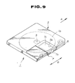
- information signals may be written or read on or from the disc 1 by disposing the disc cartridge as shown in Figures 9 to 14. That is, information signals are not pre-recorded on the magneto-optical disc of the present disc cartridge, but information signals may be written, erased and read on or from the disc 1 b . It is noted that control data necessary for writing the information signals, such as address data, are pre-recorded on the magneto-optical disc 1 b .
- the cartridge body 2 of the disc cartridge 1 includes the aperture 5 a for the optical pickup device and the chucking aperture 6, similar to those of the cartridge body 2 of the disc cartridge 1 associated with the optical disc 1 a , and the first and second disc type indicators 9 and 10.
- the magneto-optical disc 1 b is accommodated in the cartridge body 2.
- An aperture 5 b for a magnetic head similar in contour to the aperture for the optical pickup device 5 a , is formed in the upper major wall 2 a of the cartridge body 2.
- the aperture 5 b for the magnetic head is in register with the aperture 5 a for the optical pickup device with the magneto-optical disc 1 b in-between.
- the shutter member 7 is mounted on the cartridge body 2 to open and close the apertures 5 a and 5 b .
- the shutter member 7 is provided with a slide portion 7 a , a lower plate portion 7 b , and an upper plate portion 7 c supported by the slide portion 7 a , similarly to the lower portion 7 b .
- the plate 7 is formed integrally from a metal plate or a sheet of synthetic resin, such as polyacetal resin, so as to present a U-shaped cross-sectional profile.
- the upper plate portion 7 c is formed as a rectangular plate of a size larger than the aperture for the magnetic head 5 b to close the aperture for the magnetic head 5 b .
- the upper plate portion 7 c has a proximal side thereof supported by the lower side of the slide portion 7 a and is faced by the lower plate portion 7 b to extend parallel thereto.
- the shutter member 7 is mounted on the cartridge body 2 so that, when the shutter member 7 is slid with respect to the cartridge body 2, the plate portions 7 b , 7 c , are moved between a position of closing the apertures 5 a , 5 b and a position of opening the apertures 5 a , 5 b .
- the first disc type indicator 9 is recessed and has an opening 9 a , whereas the second disc type indicator 10 is flat.
- the indicating state of the disc type indicators 9, 10 is shown as being "0, 1".
- the indicating state "0, 1" indicates that the disc is a magneto-optical disc 1 b capable of reading and writing information signals, that is that the recording layer of the magneto-optical disc 1 b is the magnetic film so that information signals may be written on the disc 1 b by the disc recording and/or reproducing apparatus.
- the cartridge body 2 thereof is loaded in position within the cartridge loading section provided on the chassis.
- the indicating states of the first and second disc type indicators 9, 10 are detected, and the operating states of the optical pickup device are set to conform to the magneto-optical disc 1 b , on the basis of the indicating states as detected by the indicators 9, 10. If, after detection of the indicating states corresponding to that of the magneto-optical disc 1 b , the recording mode or the erasure mode is set in the disc recording and/or reproducing apparatus, the magnetic head device, provided for facing the optical pickup device, may be rendered operative.
- the magnetic head device In the recording and erasure modes, the magnetic head device is drawn close to the major surface of the magneto-optical disc 1 b opposite to the major surface thereof provided with the information signals in the form of pits, via the aperture for the magnetic head 5 b , to apply a magnetic field to the signal recording region.
- information signals are read from the magneto-optical disc 1 b in the read mode by the optical pickup device via the aperture for the optical pickup device 5 a , while information signals are recoded or erased on or from the magneto-optical disc 1 b in the recording or erasure modes by the optical pickup device or by the magnetic head device.
- the opening 9 a of the first disc type indicator 9 may be opened or closed by an indication changing member 14 provided in the cartridge body 2, as shown in Figures 12 to 16.
- the indication changing member 14 is formed as a substantially rectangular plate which is clampedly held between a supporting plate 16 provided within the cartridge body 2 and an outer wall of the cartridge body 2 so as to be slid in the longitudinal direction.
- the indication changing member 14 has its one end in register with a rim of the opening 9 a of the first disc type indicator 9.
- the major surface of the indication changing member 14 is formed with a lug 14 a by which the member 14 may be slid.
- the lug 14 a is exposed to outside via an elongate opening 15 provided in the vicinity of the openings 9 a .
- the indication changing member 14 is slid in the longitudinal direction of the elongate opening 15.
- the indication changing member 14 is slid towards the opening 9 a , it is moved at the one end thereof over the opening 9 a closing the opening 9 a .
- the first disc type indicator 9 is substantially in the flat state.
- the indicating state of the disc type indicators 9, 10 of the disc cartridge 1 is then "1, 1".
- This indicating state corresponds to that of the magneto-optical disc 1 b which is a recoding-only disc, so that writing or erasure of the information signals on or from the magneto-optical disc 1 b by the disc recording and/or reproducing apparatus cannot be made.
- information signals can only be read from the magneto-optical disc 1 b by the optical pickup device, while writing and erasure of information signals on or from the magneto-optical disc 1 b by the disc recording and/or reproducing apparatus is inhibited. That is, the magnetic head device of the disc recording and/or reproducing apparatus is in the non-operative state.
- an indicating state is detected which is similar to that when the disc type indicators 9, 10 are both in the recessed states.
- the indicating state at this time is "0, 0", indicating that the disc cartridge 1 is not loaded in the disc recording and/or reproducing apparatus.
- both the optical pickup device and the magnetic head device are in the non-operative states.
- the disc cartridge of the invention is not limited to the arrangement of the preceding embodiments.
- the disc type indicators 9. 10 may be arrayed in a direction at right angles to the inserting direction on the lower major surface 2 b of the cartridge body 2 at the forward end in the inserting direction. In this case, detection of the indicating states of the disc type indicators 9, 10 may be facilitated because these indicators may be detected in the course of insertion of the disc cartridge into the inside of the disc recording and/or reproducing apparatus.
- a cartridge body 111 is composed of an upper cartridge half and a lower cartridge half connected to each other.
- An optical disc 112 is rotatably accommodated in the cartridge body 111.
- the optical disc 112 may be any one of a recordable low-reflectance optical disc, such as the above mentioned magneto-optical disc, a read-only high-reflectance optical disc, provided with a highly reflective layer of e.g. aluminium on the disc substrate thereof, or a read-only low reflectance optical disc, provided with a reflective film of substantially the same reflectance as that of the low reflectance magneto-optical disc.
- a through-hole 113 is formed at the centre of the bottom wall of the cartridge body 111.
- a turntable intrudes via the through-hole so that the disc 112 is set on a disc table.
- the cartridge body 111 is also formed with an aperture 114 by means of which the optical pickup device of the disc recording and/or reproducing apparatus can face the signal recording region of the disc 112.
- the aperture 114 is normally closed by a shutter 115 and, when the disc cartridge 110 moved in the direction shown by an arrow A in Figure 18, so as to be loaded in position within the disc recording and/or reproducing apparatus, the shutter 115 is slid to open the aperture 114.
- Positioning holes 103, 104 in the present embodiment are circular and oblong, respectively.
- a notch 105 can be engaged by a loading unit on intrusion of the disc cartridge into the disc recording and/or reproducing apparatus.
- the shutter 15 is opened by shutter opening means provided in the disc recording and/or reproducing apparatus, at the same time that the positioning holes 103, 104 are engaged by positioning pins provided in the apparatus to set the loading position of the disc cartridge 110.
- the above described disc cartridge 110 is provided with several discriminating means at rear corners of the bottom of the cartridge body 111.
- a discriminating hole 101 prevents inadvertent erasure.
- a detection unit not shown provided in the disc recording and/or reproducing apparatus, detects whether the discriminating hole 101 is open or closed to determine whether or not recording is feasible.
- a knob 116 of a slider can open or close the hole 101.
- a discriminating hole 102 indicating reflectance of the optical disc 112 accommodated within the cartridge body 111 is formed in the cartridge body 111 adjacent to the discriminating hole 101 for inhibiting inadvertent erasure.
- the discriminating hole 102 is opened and closed according to whether the disc accommodated within the cartridge body 111 is of low reflectance or high reflectance or vice versa. This is detected by the disc recording and/or reproducing apparatus correspondingly to adjust the level of the laser power irradiated by the optical pickup device on the optical disc.
- Figure 20 shows, in a block diagram, a system for detecting the discriminating hole 102 of the disc cartridge 110 of the dis recording and/or reproducing apparatus for setting the laser powe as a function of reflectance of the optical disc 112.
- 117 denotes a turntable to set the optical disc 112 within the disc cartridge 110
- 118 a spindle motor rotationally to drive the turntable 117
- 119 an optical pickup device to irradiate the signal recording region of the optical disc 112 with a laser beam to write or read information signals.
- a detection switch 120 is provided in association with the discriminating hole 102 of the disc cartridge 110. The detection switch 120 is not thrust and hence is turned off when the discriminating hole 102 is open, while the detection switch 120 is thrust and turned on when the discriminating hole 102 is closed, so that the output level of the laser power may be changed correspondingly.
- the detection switch 120 detects whether the discriminating hole 102 of the disc cartridge 110 is open or closed and, depending on an output from the detection switch 120, the microcomputer 121 proceeds to determining if the optical disc 112 within the disc cartridge 110 is of low reflectance or high reflectance.
- the microcomputer 121 accordingly sets the light beam from the optical pickup device to an optimum output level to transmit a corresponding driving signal to a laser driving circuit 123 so that a laser light having an output corresponding to the reflectance of the optical disc 112 is irradiated on the disc by the optical pickup device 119. Simultaneously, the microcomputer 121 sets a servo gain proportionate to reflectance of the disc 112 to transit a corresponding signal to a servo circuit 124 so that focusing and tracking servo control operations as well as the reading servo operation is effected satisfactorily by a driving coil 126 of the optical pickup device 119 for reading signals from the optical disc 112.
- RF signals read by the optical pickup device 119 are supplied via an RF amplifier 125 to the servo control circuits 122, 124 so that the focusing, tracking and threading servo operations are effected continuously on the basis of these RF signals by the spindle motor 118 and the optical pickup device 119.
- a part of an output from the RF amplifier 125 is transmitted to a signal processor 127 for decoding or like processing operations before being outputted at an output terminal 128.
- a magnetic head 129 forms an external magnetic field generator which has its operation controlled by control signals from the microcomputer 121, as will be explained subsequently.
- a discriminating hole 102 indicating disc reflectance Since only one discriminating hole 102 indicating disc reflectance is provided in the above embodiment, it is only possible to discriminate a disc of high reflectance and a disc of low reflectance from each other. If the different optical discs exhibit three to four different values of reflectance, a second discriminating hole 102' may be provided, as indicated by a broken line in Figure 19. In this case, four different values of reflectance R 1 to R 4 may be discriminated from one another, as shown in Table 1, by the combination of the open and closed states of the discriminating holes 102 and 102'.
- DISCRIMINATING HOLE 102 DISCRIMINATING HOLE 102' REFLECTANCE OPEN OPEN R 1 OPEN CLOSED R 2 CLOSED OPEN R 3 CLOSED CLOSED R 4
- the presence of absence of the disc cartridge may be discriminated by setting reflectance R 1 to approximately 0%.
- the information signals recorded on the optical disc may be read reliably.
- a thread motor When reading information signals recorded on the optical disc, a thread motor is driven by control signals from the microcomputer 121 from an inner periphery of the optical disc.
- Table-of-contents data (TOC data) are recorded in the inner peripheral region radially inwardly of the signal recording region.
- the optical pickup device reads out the TOC data with a laser power as set by detecting the discriminating hole.
- the TOC data include various data concerning the optical disc. That is, by the optical pickup reading the TOC data, the microcomputer 121 proceeds to determine the disc type, that is whether the disc is of the recordable type or of the read-only type, and the recording format, such as signal format. Then, depending on the type of the optical disc, the signal processing operation performed by the signal processor 127 or the driving control state of the magnetic head is changedover to perform the recording and/or reproducing operations.
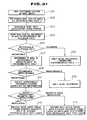
- Figure 21 shows the sequence of the above operations by a flow sheet.
- the discriminating holes 102, 102' are detected at step 202 for discriminating disc reflectance.
- the laser power of a laser from an optical pickup device 119 is set in accordance with the results of step 202 for irradiating the disc at step 203.
- the TOC data of the optical disc is read to determine if the disc is of the recordable disc or a read-only disc and the signal format type at step 204. If the disc is a read-only disc, the reading operation (playback) is performed at step 206. At this time, the presence of the discriminating hole for inhibiting inadvertent erasure 101 is disregarded.
- the discriminating hole 101 of the disc cartridge 110 is detected to determine whether the optical disc 112 is in the recordable state or in the unrecordable state, that is, in the inadvertent erasure inhibiting state (steps 207, 208). If the optical disc 112 is in the unrecordable state, only the reading operation (playback) is performed (step 209).
- the recording system appropriate for the optical disc 112 is selected (step 210). That is, if the magneto-optical disc is used as a recordable disc, the recording system is one of the light modulating recording system and the magnetic field modulation recording system.
- the magnetic field head 129 as an external magnetic field generator for generating a recording modulating magnetic field, is floated with respect to the magneto-optical disc, while a light beam of the recording power level is irradiated on the disc by the optical pickup device, at the same time that an active servo is applied to control the magnetic field head 129 to remove the magnetic field head a predetermined distance from the magneto-optical disc, or the magnetic field head 129 is brought into sliding contact with the magneto-optical disc for writing information signals on the magneto-optical disc.
- Information reading from the optical disc is by only the light beam from the optical pickup device (step 212).
- the light beam from the optical pickup device is controlled to be turned on and off based on information signals to be recorded, while the unidirectional magnetic field is applied from the magnetic field head as the external magnetic field generator, for writing information signals on the optical disc.
- information reading from the optical disc is by only the optical pickup, as in the case of the magnetic field modulating system (step 213).
- disc types include a low reflectance recordable disc (magneto-optical disc), a high reflectance read-only disc (disc with an evaporated aluminium layer) and a low reflectance read-only disc. It is also probable that a high reflectance recordable disc will make its debut, while it is necessary to discriminate between a low durability disc and a high durability disc in the case of the disc slidingly contacted by the recording magnetic field head. Besides, what types of disc will make their debuts in future is beyond estimation.
- a number of discrimination holes would be necessitated if discrimination of these items be taken charge of by corresponding discriminating holes. This is not desirable in consideration of the limited space available on the disc cartridge. If the discrimination of the basic items, such as disc reflectance, are dealt with by the discriminating holes of the disc cartridge, and the remaining items are dealt with by the TOC data of the disc, for discriminating the disc types, it becomes possible to cope easily with any disc types.
- the first and second disc type indicators provided on outer surfaces of the cartridge body having the disc rotatably accommodated therein, can be in the open or closed states, and can indicate one of the four indicating states in unison.
- the disc type may be discriminated easily. Detection of the disc type indicators may be achieved easily by microswitches or the like.
- the present invention provides a disc cartridge which will allow the type of the disc accommodated in the cartridge body thereof to be discriminated easily and which will permit a disc recording and/or reproducing apparatus to perform predetermined switching operations reliably as a function of disc types without complicating or enlarging the size of the disc recording and/or reproducing apparatus.
- the present invention can also provide an arrangement in which discriminating means for indicating reflectance of the optical disc is provided in a portion of a cartridge body having the optical disc accommodated therein, and in which the disc recording and/or reproducing apparatus is provided with means for detecting the discriminating means and means for setting the power of a laser light irradiated on the optical disc as a function of an output of the detection means, so that reflectance of the optical disc may be determined automatically and the laser power may be set in conformity to the discriminated reflectance reliably to read the signals recorded on the optical disc. If reflectance of the optical disc is first discriminated by the discriminating means of the disc cartridge as described above and the TOC information recorded on the optical disc is read for discriminating the type of the optical disc, in accordance with the invention, any disc type may be coped with easily.
Abstract
Description
- The invention relates to a disc cartridge having an optical disc accommodated therein.
- Such a disc may be a read-only optical disc or a magneto-optical disc for re-recording information signals.
- Optical discs have hitherto been proposed as a recording medium for example for musical signals. Such optical discs can be classified into read-only optical discs used only for reproducing pre-recorded information signals and magneto-optical discs for overwriting or re-recording information signals after erasure of information signals previously recorded on the disc.
- With a read-only optical disc, information signals are pre-recorded in a pattern of projections and recesses or pits on one major surface of a disc substrate formed of a light-transmitting synthetic resin, such as a polycarbonate resin. A light beam reflective layer of e.g. aluminium is applied to the major surface of the disc substrate carrying the pits. With a magneto-optical disc as an overwrite type optical disc, a signal recording layer of a thin magnetic film is provided on a major surface of the disc substrate formed of a light-transmitting material.
- With each of the optical discs, the rim portion of a centre hole is designed as a chucking region to be chucked by a disc rotating unit provided in a disc recording and/or reproducing apparatus for recording and/or reproducing information signals on or from the disc. Thus, with each optical disc, an outer peripheral region of the major surface of the disc exclusive of the inner peripheral chucking section is used as a signal recording region.
- To prevent deposition of dust and dirt and contact with hands or fingers of at least the signal recording region of the optical disc, the disc is disposed as a disc cartridge by being housed in a cartridge body which is composed of an upper cartridge half and a lower cartridge half abutted and connected to each other.
- With the disc cartridge, the optical disc accommodated in the cartridge body can be rotated in the cartridge body. A major surface of the cartridge body is formed with a chucking aperture to expose the chucking region of the disc to outside, and a signal recording/reproducing aperture to expose at least a part of the signal recording region of the disc to outside. Thus the optical disc has its chucking region chucked by the disc rotating unit of the disc recording and/or reproducing apparatus via the chucking aperture, while information signals are recorded on or read from the signal recording region via the recording/reproducing aperture.
- The information signals are read from the optical disc by the disc recording and/or reproducing apparatus by a light beam irradiated on the signal recording region. The light beam is radiated from an optical pickup device of the disc recording and/or reproducing apparatus so as to converge on the signal recording region of the optical disc. The optical pickup device can radiate the light beam and detect the return light reflected back from the signal recording layer of the optical disc.
- Information signals can be written on the optical disc by the disc recording and/or reproducing apparatus by a light beam irradiated on the signal recording region of the disc and by a magnetic field applied to the signal recording layer. The magnetic field is applied to the signal recording region by a magnetic head provided in the disc recording and/or reproducing apparatus as an external magnetic field generator on the opposite side of the optical disc with respect to the optical pickup device.
- Meanwhile, disc recording and/or reproducing apparatus has been proposed which may be used with both a read-only optical disc and a magneto-optical disc as recording medium. When a disc cartridge having a read-only optical disc accommodated therein is introduced into the disc recording and/or reproducing apparatus, the apparatus reads information signals pre-recorded in the signal recording region of the disc in the form of pits. When a disc cartridge having a magneto-optical disc in introduced into the disc recording and/or reproducing apparatus, the apparatus writes and reads information signals on or from the signal recording region of the disc.
- In a disc recording and/or reproducing apparatus, which may be used with both the optical disc and the magneto-optical disc, it is necessary to changeover an output of the light beam irradiated on the disc by the optical pickup device depending on the type of the disc, that is on whether the disc is an optical disc on which information signals may be recorded or a read-only optical disc.
- The reason is that reflectance of the read-only optical disc, that is an optical disc on which aluminium is deposited, is as high as 80% or higher, whereas that of the overwrite type optical disc, such as magneto-optical disc, is significantly lower and approximately 15 to 30%.
- In addition, it is necessary with such disc recording and/or reproducing apparatus to change over the magnetic head between its operative and non-operative states depending on which of the optical discs is to be in use.
- The optical pickup device and the magnetic head can be changedover by the user of the disc recording and/or reproducing apparatus by a manual switching operation. However, a mistaken changeover operation may give rise to destruction of the magnetic head or optical pickup device. Such mistaken operation also may give rise to inadvertent erasure of recorded information signals. It is therefore desirable for the changeover operation in disc recording and/or reproducing apparatus dependent on the disc type to be performed reliably without the possibility of mistaken operations.
- It could be contemplated to render the size and/or the shape of the disc cartridge variable depending on the type of the optical disc. However, if the size and/or the shape of the disc should be selected freely, the disc recording and/or reproducing apparatus is necessarily complicated in structure.
- It may also be contemplated to irradiate the optical disc with a predetermined amount of light and to detect the volume of light reflected from the optical disc to determine the disc type based on the difference in reflectance of the signal recording region of the optical disc. However, if reflectance of the signal recording region is to be detected in the disc recording and/or reproducing apparatus, the disc recording and/or reproducing apparatus is again necessarily complicated in structure. On the other hand, with the method of detecting the volume of light reflected from the optical disc to determine the disc type, since the disc is once irradiated with a light beam and the disc type is determined on the basis of the return light from the optical disc, the disc type cannot be determined promptly. That is, the disc type can be determined only after the disc recording and/or reproducing apparatus has been driven for operation.
- According to one aspect of the invention there is provided a disc cartridge comprising:
- a cartridge body having an optical disc rotatably accommodated therein and having an aperture to expose a part of a signal recording region of the optical disc to outside;
- a shutter movably mounted on the cartridge body and to open or close the aperture of the cartridge body; and
- first and second discriminating sections provided on outer sides of the cartridge body to indicate the type of the optical disc accommodated within the cartridge body.
-
- According to another aspect of the invention there is provided a disc cartridge used with a disc recording and/or reproducing apparatus to record and/or reproduce information signals on two or more discs having different values of reflectance comprising:
- a cartridge body having an optical disc rotatably accommodated therein and having an aperture to expose a part of a signal recording region of the optical disc to outside;
- a shutter movably mounted on the cartridge body to open or close the aperture of the cartridge body; and
- discriminating means to indicate reflectance of the optical disc accommodated in the cartridge body.
-
- According to yet another aspect of the invention there is provided a disc recording and/or reproducing apparatus employing a disc cartridge including discriminating means to indicate reflectance of an optical disc housed in a cartridge body thereof, the disc recording and/or reproducing apparatus recording and/or reproducing information signals on or from the optical disc housed in the cartridge body, the apparatus comprising:
- detecting means to detect the discriminating means; and
- setting means to set an output level of a laser light irradiated on the optical disc based on a detection output from the detecting means.
-
- According to a further aspect of the invention there is provided a disc recording and/or reproducing apparatus employing a disc cartridge including discriminating means to indicate reflectance of an optical disc housed in a cartridge body thereof, the disc recording and/or reproducing apparatus recording and/or reproducing information signals on or from the optical disc housed in the disc cartridge by at least an optical pickup, the apparatus comprising:
- servo means to control a light beam irradiated on the optical disc by the optical pickup;
- disc rotating means rotationally to drive the optical disc;
- detecting means to detect the discriminating means;
- setting means to set an output level of the light beam irradiated on the optical disc from the optical pickup based on an output from the detecting means; and
- controlling means to control the gains of the servo means and the disc driving means based on the detected output of the detecting means.
-
- According to a still further aspect of the invention there is provided a method of recording and/or reproducing information signals on or from an optical disc, using a disc cartridge including discriminating means to indicate reflectance of the optical disc accommodated in a cartridge body thereof, comprising:
- detecting the discriminating means of the disc cartridge in a loaded position;
- setting an output level of a light beam irradiated on the optical disc in the disc cartridge based on the results of detection of the discriminating means;
- reading table-of-contents data of the optical disc by the light beam the output level of which has been set on the basis of the results of detection of the discriminating means; and
- controlling recording and/or reproducing means to record and/or reproduce information signals based on the read table-of-contents data of the optical disc.
-
- In a disc cartridge the type of the optical disc accommodated therein may thus be determined easily and promptly.
- Disc recording and/or reproducing apparatus which makes use of such a disc cartridge need not be increased excessively in size and need not be complex in structure and changeover operation of the recording and/or reproducing modes thereof depending on the type of the disc accommodated within the disc cartridge can be effected correctly.
- The invention is diagrammatically illustrated by way of example in the accompanying drawings, in which:-
- Figure 1 is a perspective view, when seen from above, of a disc cartridge having accommodated therein a read-only optical disc according to a first embodiment of the invention;
- Figure 2 is a perspective view, when seen from below, of the disc cartridge shown in Figure 1;
- Figure 3 is a plan view of the disc cartridge shown in Figure 1;
- Figure 4 is a bottom view of the disc cartridge shown in Figure 1;
- Figure 5 is a perspective view showing the construction of a disc cartridge having accommodated therein a magneto-optical disc only for reproducing information signals according to the invention;
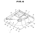
- Figure 6 is a perspective view, when see from below, of the disc cartridge shown in Figure 5;
- Figure 7 is a plan view of the disc cartridge shown in Figure 5;
- Figure 8 is a bottom view of the disc cartridge shown in Figure 5;
- Figure 9 is a perspective view showing the construction of a disc cartridge having accommodated therein a magneto-optical disc for writing information signals according to the invention;
- Figure 10 is a perspective view, when seen from below, of the disc cartridge shown in Figure 9;
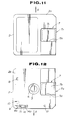
- Figure 11 is a plan view of the disc cartridge shown in Figure 9;
- Figure 12 is a bottom view of the disc cartridge shown in Figure 9;
- Figure 13 is a perspective view, as seen from below, of the disc cartridge shown in Figure 9, showing the state in which writing of information signals is inhibited;
- Figure 14 is a bottom view of the disc cartridge shown in Figure 9 showing the state in which writing of information signals is inhibited;
- Figure 15 is a partial longitudinal cross-sectional view showing the construction of a first disc type indicator of the disc cartridge shown in Figure 9;
- Figure 16 is a partial longitudinal cross-sectional view showing the construction of the first disc type indicator of the disc cartridge shown in Figure 9, showing the state in which an opening of the indicator is closed;
- Figure 17 is a bottom view showing a second embodiment of the disc cartridge according to the invention;
- Figure 18 is a perspective view of a disc cartridge according to a third embodiment of the invention, shown in an inverted state;
- Figure 19 is a plan view showing a critical portion of the disc cartridge shown in Figure 18;
- Figure 20 is a block diagram showing the construction of a system for detecting a discrimination hole in the disc cartridge for setting laser power; and
- Figure 21 is a block diagram for illustrating the operation of discriminating the disc type and recording and/or reproducing information signals.
-
- Referring to the drawings and firstly to Figures 1 to 4, in a first embodiment, a disc cartridge 1 has accommodated therein a so-called optical disc or a magneto optical disc. The disc cartridge 1 comprises a
cartridge body 2 having an optical disc 1a accommodated therein, and ashutter member 7 thereon. The optical disc 1a comprises a disc-shaped disc base plate or a substrate, formed of a transparent synthetic resin, such as polycarbonate, and a signal recording layer deposited on a major surface of the disc substrate and made up of a thin metal film and a reflective film. The optical disc 1a is a so-called read-only optical disc and writing of information signals on the signal recording layer thereof is effected by transferring a pattern of projections and recesses, that is pits, from a stamper onto the disc substrate. An aluminium reflective layer is deposited on the major surface of the disc substrate provided with the pits such as by sputtering or evaporation. - With the optical disc, the rim part of a
centre hole 3 functions as a chucking region to be chucked by a disc rotating unit of the disc recording and/or reproducing apparatus which can record and/or reproduce information signals on or from the disc. Thus, with the optical disc, the outer peripheral part of the major surface of the disc, exclusive of the inner peripheral chucking region thereof, functions as a signal recording region. A recording track in which predetermined information signals are recorded is formed helically with the centre of curvature of the helix coincident with the centre of the centre hole. - The
cartridge body 2 is formed as a thin rectangular casing made up of an upper cartridge half and a lower cartridge half abutted and connected to each other. That is, upper and lowermajor walls cartridge body 2 facing the major surfaces of the optical disc 1a housed therein are each in the form of a square having each side slightly longer than the diameter of the optical disc 1a. The optical disc 1a is housed in thecartridge body 2 so that the major surface thereof provided with asignal recording region 4 is faced by the lowermajor wall 2b and the other major surface thereof is faced by the uppermajor wall 2a. - The lower
major wall 2b of thecartridge body 2 is provided with anaperture 5a for an optical pickup device, whichaperture 5a is a substantially rectangular opening extending from a central region of the lowermajor wall 2b to close to a side of the lowermajor wall 2b, that is to close to a lateral side of thecartridge body 2. Theaperture 5a for the optical pickup device can expose a part of the signal recording region of the major surface of the disc faced by the lowermajor wall 2b to outside between the inner and outer peripheries of the optical disc 1a. In the operation of the disc recording and/or reproducing apparatus, information signals are read from the optical disc 1a by the optical pickup device via theaperture 5a for the optical pickup device. A substantiallycircular chucking aperture 6 is provided at a central part of the lowermajor wall 2b of thecartridge body 2. An inner peripheral side of the optical disc 1a, inclusive of thecentre hole 3, is exposed to outside via the chuckingaperture 6. A disc table of a disc rotating unit of the disc recording and/or reproducing apparatus can intrude into the inside of thecartridge body 2 via the chuckingaperture 6 so that the optical disc 1a is chucked by the disc chucking unit constituted by the disc table. - The
cartridge body 2 has theshutter member 7 to open and close theaperture 5a for the optical pickup device. Theshutter member 7 is a one-piece member, such as a metal plate or a plate of synthetic resin, e.g. a polyacetal, including aslide portion 7a supported by a lateral side of thecartridge body 2 and alower plate portion 7b supported by theslide portion 7a. Theslide portion 7a is in the form of an elongate bar having a thickness substantially corresponding to the thickness of thecartridge body 2. Thelower plate portion 7a is in the form of a rectangular plate larger in size than theaperture 5a for the optical pickup device to close theaperture 5a and is formed integral with theslide portion 7a by extending from the lower side of theslide portion 7a. Theshutter member 7 has itsslide portion 7a slidable relative to thecartridge body 2 so that thelower plate portion 7b may be slid with respect to thecartridge body 2 over the lowermajor wall 2b thereof. That is, theshutter member 7 may be moved with respect to thecartridge body 2 between a position of closing theaperture 5a and a position of opening theaperture 5a. - The lateral side of the
cartridge body 2 associated with theslide portion 7a of theshutter member 7 is formed with ashutter opening groove 8 which is formed to extend along the direction of insertion of the disc cartridge into the disc recording and/or reproducing apparatus as indicated by an arrow A in Figures 1 to 4, that is, along the direction of movement of theshutter member 7 indicated by an arrow b in Figure 1. - The lower
major wall 2b of thecartridge body 2 is formed with first and seconddisc type indicators disc type indicators major wall 2b opposite to the lateral side thereof provided with theshutter opening groove 8. - With the disc cartridge 1, having the optical disc 1a housed therein, the first
disc type indicator 9 is flush with the lowermajor wall 2b, while the seconddisc type indicator 10 is a recess having a predetermined depth. If, with thedisc type indicators - With the disc cartridge of the present first embodiment of the invention, the
cartridge body 2 is loaded in a cartridge loading section within the disc recording and/or reproducing apparatus. At this time, the disc cartridge 1 is loaded in position within the cartridge loading section, with thecartridge body 2 thereof being set on free ends of a plurality of positioning pins provided on the cartridge loading section and with these positioning pins being engaged in first and second positioning holes 12, 13 provided in the lowermajor wall 2b. - When the disc cartridge 1 has been loaded in position in the cartridge loading section, the first and second
disc type indicators disc type indicators cartridge body 2 when the disc cartridge 1 is loaded in position on the chassis, it is detected that the disc type indicator associated with the pushbutton switch is in a flat state, that is, the indicating state is "1". If the pushbutton switch is not thrust by thecartridge body 2 when the disc cartridge 1 is loaded in position on the chassis, it is detected that the disc type indicator associated with the pushbutton switch is in a recessed state, that is, the indicating state is "0". - With the present disc recording and/or reproducing apparatus, when the disc cartridge 1 is loaded in position in the cartridge loading section by means of the positioning pins, the optical disc 1a accommodated in the disc cartridge 1 is set on the disc table attached to a rotating shaft of a spindle motor of the disc rotating unit. The disc table is in the form of a disc smaller in diameter than the chucking
aperture 6 and larger in diameter than thecentre hole 3. When thecartridge body 2 is set in position with respect to the chassis, the disc table intrudes into the inside of thecartridge body 2 via the chuckingaperture 6. The rim part of thecentre hole 3 in the major surface of the optical disc 1a is placed on the upper surface of the disc table intruded into thecartridge body 2. At this time, the optical disc 1a is spaced apart from the inner wall surface of thecartridge body 2. Theshutter member 7 is slid, by the operation of a shutter member opening unit provided in the disc recording and/or reproducing apparatus, with respect to thecartridge body 2, to open theaperture 5a for the optical pickup device. At this time, information signals may be read from the optical disc 1a via theaperture 5a for the optical pickup device. - With the disc recording and/or reproducing apparatus, the optical pickup device, movably supported with respect to the chassis, reads information signals for the optical disc 1a. The optical pickup device is faced by the signal recording region of the optical disc 1a and moved by transfer means, not shown, between inner and outer peripheries of the optical disc 1a. The optical pickup device can irradiate the signal recording region of the disc 1a with a light beam to read information signals from the signal recording region based on the light reflected from the signal recording region.
- The operating states of the optical pickup device, that is the output of the light beam or the state of modulation, are set depending on the indicating states detected by the
disc type indicators - Referring to Figures 5 to 8, the disc cartridge 1, if used in conjunction with a magneto-
optical disc 1b, is made up of thecartridge body 2 in which the magneto-optical disc 1b is housed, and theshutter member 7. - The magneto-
optical disc 1b is made up of a disc-shaped substrate, formed of a transparent synthetic resin, such as polycarbonate, and a signal recording layer, inclusive of a magnetic layer of a magnetic material, deposited on one of the major surfaces of the disc shaped substrate by evaporation or sputtering. Although the magneto-optical disc 1b may be used for writing, erasing and reading information signals, it may also be used for only reading pre-recorded information signals, that is, it may be designed as a so-called read-only optical disc. It is assumed that the disc cartridge 1 of the present embodiment has housed therein such magneto-optical disc 1b designed as a read-only disc. - The magneto-
optical disc 1b is provided with acentre hole 3, as in the above optical disc 1a. A region of one of the major surfaces of thedisc 1b, extending towards an outer rim from the inner peripheral chucking region inclusive of thecentre hole 3, is used as thesignal recording region 4. - Similarly to the
cartridge body 2 in the disc cartridge 1 associated with the read-only optical disc 1a, thecartridge body 2 includes theaperture 5a for the optical pickup device, the chuckingaperture 6 and the first and seconddisc type indicators optical disc 1b housed therein, and theshutter member 7. - With the present disc cartridge 1, having housed therein the magneto-
optical disc 1b, the firstdisc type indicator 9 is in a flat state, that is, flush with the lowermajor wall 2b. The seconddisc type indicator 10 is similarly in the flat state. That is, the indicating states of thedisc type indicators optical disc 1b in which the signal recording layer has the magnetic layer, and hence information signals cannot be written on thedisc 1b by the disc recording and/or reproducing apparatus. - When the present disc cartridge 1, associated with the read-only magneto-
optical disc 1b, is used in the disc recording and/or reproducing apparatus, thecartridge body 2 thereof is loaded in position within the cartridge loading section. At this time, the indicating states of the first and seconddisc type indicators optical disc 1b, on the basis of the indicating states as detected by theindicators optical disc 1b by the optical pickup device via the aperture for theoptical pickup device 5a. - If the magneto-
optical disc 1b is used in conjunction with the disc cartridge 1, information signals may be written or read on or from the disc 1 by disposing the disc cartridge as shown in Figures 9 to 14. That is, information signals are not pre-recorded on the magneto-optical disc of the present disc cartridge, but information signals may be written, erased and read on or from thedisc 1b. It is noted that control data necessary for writing the information signals, such as address data, are pre-recorded on the magneto-optical disc 1b. - The
cartridge body 2 of the disc cartridge 1 includes theaperture 5a for the optical pickup device and the chuckingaperture 6, similar to those of thecartridge body 2 of the disc cartridge 1 associated with the optical disc 1a, and the first and seconddisc type indicators optical disc 1b is accommodated in thecartridge body 2. Anaperture 5b for a magnetic head, similar in contour to the aperture for theoptical pickup device 5a, is formed in the uppermajor wall 2a of thecartridge body 2. Theaperture 5b for the magnetic head is in register with theaperture 5a for the optical pickup device with the magneto-optical disc 1b in-between. - The
shutter member 7 is mounted on thecartridge body 2 to open and close theapertures shutter member 7 is provided with aslide portion 7a, alower plate portion 7b, and anupper plate portion 7c supported by theslide portion 7a, similarly to thelower portion 7b. Theplate 7 is formed integrally from a metal plate or a sheet of synthetic resin, such as polyacetal resin, so as to present a U-shaped cross-sectional profile. Theupper plate portion 7c is formed as a rectangular plate of a size larger than the aperture for themagnetic head 5b to close the aperture for themagnetic head 5b. Theupper plate portion 7c has a proximal side thereof supported by the lower side of theslide portion 7a and is faced by thelower plate portion 7b to extend parallel thereto. Theshutter member 7 is mounted on thecartridge body 2 so that, when theshutter member 7 is slid with respect to thecartridge body 2, theplate portions apertures apertures - With the present disc cartridge 1, associated with the magneto-
optical disc 1b, the firstdisc type indicator 9 is recessed and has anopening 9a, whereas the seconddisc type indicator 10 is flat. Thus the indicating state of thedisc type indicators optical disc 1b capable of reading and writing information signals, that is that the recording layer of the magneto-optical disc 1b is the magnetic film so that information signals may be written on thedisc 1b by the disc recording and/or reproducing apparatus. - When the present disc cartridge 1, associated with the overwrite type magneto-
optical disc 1b, is used in the disc recording and/or reproducing apparatus, thecartridge body 2 thereof is loaded in position within the cartridge loading section provided on the chassis. - At this time, the indicating states of the first and second
disc type indicators optical disc 1b, on the basis of the indicating states as detected by theindicators optical disc 1b, the recording mode or the erasure mode is set in the disc recording and/or reproducing apparatus, the magnetic head device, provided for facing the optical pickup device, may be rendered operative. In the recording and erasure modes, the magnetic head device is drawn close to the major surface of the magneto-optical disc 1b opposite to the major surface thereof provided with the information signals in the form of pits, via the aperture for themagnetic head 5b, to apply a magnetic field to the signal recording region. - With the present disc recording and/or reproducing apparatus, information signals are read from the magneto-
optical disc 1b in the read mode by the optical pickup device via the aperture for theoptical pickup device 5a, while information signals are recoded or erased on or from the magneto-optical disc 1b in the recording or erasure modes by the optical pickup device or by the magnetic head device. - The
opening 9a of the firstdisc type indicator 9 may be opened or closed by anindication changing member 14 provided in thecartridge body 2, as shown in Figures 12 to 16. - Referring to Figure 16, the
indication changing member 14 is formed as a substantially rectangular plate which is clampedly held between a supportingplate 16 provided within thecartridge body 2 and an outer wall of thecartridge body 2 so as to be slid in the longitudinal direction. Theindication changing member 14 has its one end in register with a rim of theopening 9a of the firstdisc type indicator 9. The major surface of theindication changing member 14 is formed with a lug 14a by which themember 14 may be slid. The lug 14a is exposed to outside via anelongate opening 15 provided in the vicinity of theopenings 9a. When the lug 14a is acted on via theelongate opening 15, theindication changing member 14 is slid in the longitudinal direction of theelongate opening 15. When theindication changing member 14 is slid towards theopening 9a, it is moved at the one end thereof over theopening 9a closing theopening 9a. - If the
opening 9a is closed by theindication changing member 14, the firstdisc type indicator 9 is substantially in the flat state. The indicating state of thedisc type indicators optical disc 1b which is a recoding-only disc, so that writing or erasure of the information signals on or from the magneto-optical disc 1b by the disc recording and/or reproducing apparatus cannot be made. Thus, with the present disc recording and/or reproducing apparatus, information signals can only be read from the magneto-optical disc 1b by the optical pickup device, while writing and erasure of information signals on or from the magneto-optical disc 1b by the disc recording and/or reproducing apparatus is inhibited. That is, the magnetic head device of the disc recording and/or reproducing apparatus is in the non-operative state. - When the disc cartridge 1 is not loaded in the disc recording and/or reproducing apparatus, an indicating state is detected which is similar to that when the
disc type indicators - The disc cartridge of the invention is not limited to the arrangement of the preceding embodiments. For example, as in the disc cartridge according to a second embodiment shown in Figure 17, the
disc type indicators 9. 10 may be arrayed in a direction at right angles to the inserting direction on the lowermajor surface 2b of thecartridge body 2 at the forward end in the inserting direction. In this case, detection of the indicating states of thedisc type indicators - The construction and operation of a disc recording and/or reproducing apparatus employing a disc cartridge of the invention will be explained by referring to the drawings and in conjunction with a disc cartridge according to a third embodiment of the invention.
- Referring to Figures 18 and 19, 110 denotes a disc cartridge of the third embodiment of the present invention. A
cartridge body 111 is composed of an upper cartridge half and a lower cartridge half connected to each other. Anoptical disc 112 is rotatably accommodated in thecartridge body 111. Theoptical disc 112 may be any one of a recordable low-reflectance optical disc, such as the above mentioned magneto-optical disc, a read-only high-reflectance optical disc, provided with a highly reflective layer of e.g. aluminium on the disc substrate thereof, or a read-only low reflectance optical disc, provided with a reflective film of substantially the same reflectance as that of the low reflectance magneto-optical disc. A through-hole 113 is formed at the centre of the bottom wall of thecartridge body 111. When thedisc cartridge 110 is loaded into disc recording and/or reproducing apparatus, a turntable intrudes via the through-hole so that thedisc 112 is set on a disc table. Thecartridge body 111 is also formed with anaperture 114 by means of which the optical pickup device of the disc recording and/or reproducing apparatus can face the signal recording region of thedisc 112. Theaperture 114 is normally closed by ashutter 115 and, when thedisc cartridge 110 moved in the direction shown by an arrow A in Figure 18, so as to be loaded in position within the disc recording and/or reproducing apparatus, theshutter 115 is slid to open theaperture 114. Positioning holes 103, 104 in the present embodiment are circular and oblong, respectively. anotch 105 can be engaged by a loading unit on intrusion of the disc cartridge into the disc recording and/or reproducing apparatus. When thedisc cartridge 110 is loaded in the disc recording and/or reproducing apparatus, theshutter 15 is opened by shutter opening means provided in the disc recording and/or reproducing apparatus, at the same time that the positioning holes 103, 104 are engaged by positioning pins provided in the apparatus to set the loading position of thedisc cartridge 110. - The above described
disc cartridge 110 is provided with several discriminating means at rear corners of the bottom of thecartridge body 111. A discriminatinghole 101 prevents inadvertent erasure. A detection unit, not shown provided in the disc recording and/or reproducing apparatus, detects whether the discriminatinghole 101 is open or closed to determine whether or not recording is feasible. Aknob 116 of a slider, not shown, can open or close thehole 101. - A discriminating
hole 102 indicating reflectance of theoptical disc 112 accommodated within thecartridge body 111 is formed in thecartridge body 111 adjacent to thediscriminating hole 101 for inhibiting inadvertent erasure. The discriminatinghole 102 is opened and closed according to whether the disc accommodated within thecartridge body 111 is of low reflectance or high reflectance or vice versa. This is detected by the disc recording and/or reproducing apparatus correspondingly to adjust the level of the laser power irradiated by the optical pickup device on the optical disc. - Figure 20 shows, in a block diagram, a system for detecting the discriminating
hole 102 of thedisc cartridge 110 of the dis recording and/or reproducing apparatus for setting the laser powe as a function of reflectance of theoptical disc 112. In Figure 20 117 denotes a turntable to set theoptical disc 112 within thedisc cartridge 110, 118 a spindle motor rotationally to drive theturntable optical disc 112 with a laser beam to write or read information signals. Adetection switch 120 is provided in association with the discriminatinghole 102 of thedisc cartridge 110. Thedetection switch 120 is not thrust and hence is turned off when the discriminatinghole 102 is open, while thedetection switch 120 is thrust and turned on when the discriminatinghole 102 is closed, so that the output level of the laser power may be changed correspondingly. - In the present system, when the
disc cartridge 110 is loaded in the disc recording and/or reproducing apparatus, and thedisc 112 is set on theturntable 117, commands of amicrocomputer 121 are transmitted to aservo circuit 122 to drive thespindle motor 118 rotationally to drive theoptical disc 112. Simultaneously, thedetection switch 120 detects whether the discriminatinghole 102 of thedisc cartridge 110 is open or closed and, depending on an output from thedetection switch 120, themicrocomputer 121 proceeds to determining if theoptical disc 112 within thedisc cartridge 110 is of low reflectance or high reflectance. Themicrocomputer 121 accordingly sets the light beam from the optical pickup device to an optimum output level to transmit a corresponding driving signal to alaser driving circuit 123 so that a laser light having an output corresponding to the reflectance of theoptical disc 112 is irradiated on the disc by theoptical pickup device 119. Simultaneously, themicrocomputer 121 sets a servo gain proportionate to reflectance of thedisc 112 to transit a corresponding signal to aservo circuit 124 so that focusing and tracking servo control operations as well as the reading servo operation is effected satisfactorily by a drivingcoil 126 of theoptical pickup device 119 for reading signals from theoptical disc 112. On the other hand, RF signals read by theoptical pickup device 119 are supplied via anRF amplifier 125 to theservo control circuits spindle motor 118 and theoptical pickup device 119. A part of an output from theRF amplifier 125 is transmitted to asignal processor 127 for decoding or like processing operations before being outputted at anoutput terminal 128. Amagnetic head 129 forms an external magnetic field generator which has its operation controlled by control signals from themicrocomputer 121, as will be explained subsequently. - Since only one discriminating
hole 102 indicating disc reflectance is provided in the above embodiment, it is only possible to discriminate a disc of high reflectance and a disc of low reflectance from each other. If the different optical discs exhibit three to four different values of reflectance, a second discriminating hole 102' may be provided, as indicated by a broken line in Figure 19. In this case, four different values of reflectance R1 to R4 may be discriminated from one another, as shown in Table 1, by the combination of the open and closed states of the discriminatingholes 102 and 102'.DISCRIMINATING HOLE 102DISCRIMINATING HOLE 102' REFLECTANCE OPEN OPEN R1 OPEN CLOSED R2 CLOSED OPEN R3 CLOSED CLOSED R4 - As specific example, the presence of absence of the disc cartridge may be discriminated by setting reflectance R1 to approximately 0%.
- By detecting the discriminating hole(s) of the disc cartridge and hence the disc reflectance and correspondingly setting the laser power and the servo gain of the optical pickup device, the information signals recorded on the optical disc may be read reliably.
- When reading information signals recorded on the optical disc, a thread motor is driven by control signals from the
microcomputer 121 from an inner periphery of the optical disc. Table-of-contents data (TOC data) are recorded in the inner peripheral region radially inwardly of the signal recording region. The optical pickup device reads out the TOC data with a laser power as set by detecting the discriminating hole. The TOC data include various data concerning the optical disc. That is, by the optical pickup reading the TOC data, themicrocomputer 121 proceeds to determine the disc type, that is whether the disc is of the recordable type or of the read-only type, and the recording format, such as signal format. Then, depending on the type of the optical disc, the signal processing operation performed by thesignal processor 127 or the driving control state of the magnetic head is changedover to perform the recording and/or reproducing operations. - Figure 21 shows the sequence of the above operations by a flow sheet. When the
disc cartridge 110 is first loaded atstep 201 in the disc recording and/or reproducing apparatus, the discriminatingholes 102, 102' are detected atstep 202 for discriminating disc reflectance. The laser power of a laser from anoptical pickup device 119 is set in accordance with the results ofstep 202 for irradiating the disc atstep 203. - The TOC data of the optical disc is read to determine if the disc is of the recordable disc or a read-only disc and the signal format type at step 204. If the disc is a read-only disc, the reading operation (playback) is performed at
step 206. At this time, the presence of the discriminating hole for inhibitinginadvertent erasure 101 is disregarded. - If the results of discrimination indicate that the disc is of the recordable type, the discriminating
hole 101 of thedisc cartridge 110 is detected to determine whether theoptical disc 112 is in the recordable state or in the unrecordable state, that is, in the inadvertent erasure inhibiting state (steps 207, 208). If theoptical disc 112 is in the unrecordable state, only the reading operation (playback) is performed (step 209). - If the
optical disc 112 is recordable, the recording system appropriate for theoptical disc 112 is selected (step 210). That is, if the magneto-optical disc is used as a recordable disc, the recording system is one of the light modulating recording system and the magnetic field modulation recording system. - If the recording system is the magnetic field modulation recording system, the
magnetic field head 129, as an external magnetic field generator for generating a recording modulating magnetic field, is floated with respect to the magneto-optical disc, while a light beam of the recording power level is irradiated on the disc by the optical pickup device, at the same time that an active servo is applied to control themagnetic field head 129 to remove the magnetic field head a predetermined distance from the magneto-optical disc, or themagnetic field head 129 is brought into sliding contact with the magneto-optical disc for writing information signals on the magneto-optical disc. Information reading from the optical disc is by only the light beam from the optical pickup device (step 212). In the case of the light modulation system, the light beam from the optical pickup device is controlled to be turned on and off based on information signals to be recorded, while the unidirectional magnetic field is applied from the magnetic field head as the external magnetic field generator, for writing information signals on the optical disc. On the other hand, information reading from the optical disc is by only the optical pickup, as in the case of the magnetic field modulating system (step 213). - It will be seen therefore that, with the method disclosed, determination of basic items, that is discrimination of recordability of non-recordability (inhibition of inadvertent erasure) of the disc is effected by the corresponding discriminating holes provided in the disc cartridge, while discrimination of other items is based on the results of reading of the TOC information of the optical disc.
- It is possible in this manner to cope with an increased number of disc types. That is, presently proposed disc types include a low reflectance recordable disc (magneto-optical disc), a high reflectance read-only disc (disc with an evaporated aluminium layer) and a low reflectance read-only disc. It is also probable that a high reflectance recordable disc will make its debut, while it is necessary to discriminate between a low durability disc and a high durability disc in the case of the disc slidingly contacted by the recording magnetic field head. Besides, what types of disc will make their debuts in future is beyond estimation.
- A number of discrimination holes would be necessitated if discrimination of these items be taken charge of by corresponding discriminating holes. This is not desirable in consideration of the limited space available on the disc cartridge. If the discrimination of the basic items, such as disc reflectance, are dealt with by the discriminating holes of the disc cartridge, and the remaining items are dealt with by the TOC data of the disc, for discriminating the disc types, it becomes possible to cope easily with any disc types.
- With the above described disc cartridge according to each embodiment of the invention, the first and second disc type indicators, provided on outer surfaces of the cartridge body having the disc rotatably accommodated therein, can be in the open or closed states, and can indicate one of the four indicating states in unison.
- In this manner, with the present disc cartridge, by detecting the indicating states, associated with the disc types, of the disc type indicators, the disc type may be discriminated easily. Detection of the disc type indicators may be achieved easily by microswitches or the like.
- Thus the present invention provides a disc cartridge which will allow the type of the disc accommodated in the cartridge body thereof to be discriminated easily and which will permit a disc recording and/or reproducing apparatus to perform predetermined switching operations reliably as a function of disc types without complicating or enlarging the size of the disc recording and/or reproducing apparatus.
- The present invention can also provide an arrangement in which discriminating means for indicating reflectance of the optical disc is provided in a portion of a cartridge body having the optical disc accommodated therein, and in which the disc recording and/or reproducing apparatus is provided with means for detecting the discriminating means and means for setting the power of a laser light irradiated on the optical disc as a function of an output of the detection means, so that reflectance of the optical disc may be determined automatically and the laser power may be set in conformity to the discriminated reflectance reliably to read the signals recorded on the optical disc. If reflectance of the optical disc is first discriminated by the discriminating means of the disc cartridge as described above and the TOC information recorded on the optical disc is read for discriminating the type of the optical disc, in accordance with the invention, any disc type may be coped with easily.
Claims (3)
- An optical disc recording and/or reproducing apparatus for recording or reproducing a plurality of reflectively different type of optical discs having a data recording area for recording data and a contents data area for recording contents data of the recording area, said apparatus comprising:wherein said recording and/or reproducing means reads out contents data of the optical disc housed in said disc cartridge by said optical pickup after completing the control operation of the light beam omitted from said optical pickup and the setting operation of the gain of said servo-means; anda disc cartridge including a cartridge body for housing one of said optical discs and a first discriminating portion formed on said cartridge body, said first discriminating portion for indicating the reflectivity of one of the optical discs housed in the cartridge body by a plurality of unevenness;recording and/or reproducing means for recording or reproducing to or from the optical disc housed in said disc cartridge and having an optical pickup for irradiating a light beam to the optical disc housed in said disc cartridge;a detecting switch mechanically contacted to said first discriminating portion of said disc cartridge loaded on said apparatus;servo-means for controlling the focus and the position of light beam radiated from said optical pick up on the optical disc housed in said disc cartridge; anda controller for supplying the output signal from said detecting switch and for discriminating the reflectivity of the optical disc housed in said cartridge disc, said controller for controlling the output level of the light beam emitted from said optical pickup according to the discriminating result and for setting the gain of said servo-means according to the discriminating result before recording or reproduction to or from the optical disc housed in said disc cartridge;
wherein said controller discriminates a type of the optical disc housed in said disc cartridge according to the read-out contents data and controls said recording and/or reproducing means according to the discriminating result of the contents data of the optical disc housed in said disc cartridge. - An optical disc recording and/or reproducing apparatus according to Claim 1, wherein said disc cartridge further comprises a second discriminating portion for indicating a recording condition of the optical disc housed in said disc cartridge, said second discriminating portion detected by said detecting switch, the detecting switch providing the output signal as the detection result of said second discriminating portion to the controller and the controller controlling the recording operation of said recording and/or reproducing means after reading the contents data from the optical disc housed in said disc cartridge.
- A control method for controlling an optical disc recording and/or reproducing apparatus in recording or reproducing a plurality of reflectivity of different type of optical discs having a data recording area for recording data and a contents data area for recording contents data of the recording area and housing a disc cartridge having a cartridge buddy for housing one of said optical discs and a discriminating portion formed on said cartridge body, said discriminating portion indicating the reflectivity of one of the optical discs housed in said cartridge body by a plurality of unevenness, said apparatus including a recording and/or reproducing means, a detecting switch and servo-means, said recording and/or reproducing means for recording or reproducing the optical disc housed in said disc cartridge and having an optical pickup for irradiating a light beam to the optical disc housed in said disc cartridge, said detecting switch mechanically contacted to said discriminating portion of said disc cartridge loaded on said apparatus, said servo-means for controlling the focus and the position of the light beam radiated from said optical pickup on the optical disc housed in said disc cartridge, said method comprising steps of;
detecting a discriminating portion of a disc cartridge loaded on a recording and/or reproducing apparatus by a detecting switch;
discriminating the reflectivity of an optical disc housed in said disc cartridge;
controlling the output level of a light beam omitted from an optical pickup according to the discriminating result;
setting the gain of a servo-means according to the discriminating result before recording or reproduction to or from the optical disc housed in said disc cartridge;
reading out the contents data of the optical disc housed in said disc cartridge by said optical pickup after completing the control operation of the light beam emitted from said optical pickup and the setting operation of the gain of said servo-means;
discriminating the type of the optical disc housed in said disc cartridge according to the read out contents data; and
controlling a recording and/or reproducing means according to the discriminating result of the contents data of the optical disc housed in said disc cartridge.
Priority Applications (1)
| Application Number | Priority Date | Filing Date | Title |
|---|---|---|---|
| EP04075927A EP1431976A3 (en) | 1991-02-18 | 1992-02-14 | Disc cartridge and disc recording and/or reproducing apparatus |
Applications Claiming Priority (6)
| Application Number | Priority Date | Filing Date | Title |
|---|---|---|---|
| JP4402591A JPH04263179A (en) | 1991-02-18 | 1991-02-18 | Disk cartridge |
| JP4402591 | 1991-02-18 | ||
| JP21455591 | 1991-07-31 | ||
| JP21455591A JP3210366B2 (en) | 1991-07-31 | 1991-07-31 | Optical disc recording and / or reproducing apparatus and optical disc recording and / or reproducing method |
| EP99119196A EP0974965B1 (en) | 1991-02-18 | 1992-02-14 | Disc cartridge and disc recording and/or reproducing apparatus |
| EP19920301214 EP0500271A3 (en) | 1991-02-18 | 1992-02-14 | Disc cartridge and disc recording and/or reproducing apparatus |
Related Parent Applications (1)
| Application Number | Title | Priority Date | Filing Date |
|---|---|---|---|
| EP99119196A Division EP0974965B1 (en) | 1991-02-18 | 1992-02-14 | Disc cartridge and disc recording and/or reproducing apparatus |
Related Child Applications (1)
| Application Number | Title | Priority Date | Filing Date |
|---|---|---|---|
| EP04075927A Division EP1431976A3 (en) | 1991-02-18 | 1992-02-14 | Disc cartridge and disc recording and/or reproducing apparatus |
Publications (2)
| Publication Number | Publication Date |
|---|---|
| EP1229540A1 true EP1229540A1 (en) | 2002-08-07 |
| EP1229540B1 EP1229540B1 (en) | 2004-11-10 |
Family
ID=26383875
Family Applications (4)
| Application Number | Title | Priority Date | Filing Date |
|---|---|---|---|
| EP02076374A Expired - Lifetime EP1229540B1 (en) | 1991-02-18 | 1992-02-14 | Disc cartridge and disc recording and/or reproducing apparatus |
| EP99119196A Expired - Lifetime EP0974965B1 (en) | 1991-02-18 | 1992-02-14 | Disc cartridge and disc recording and/or reproducing apparatus |
| EP19920301214 Ceased EP0500271A3 (en) | 1991-02-18 | 1992-02-14 | Disc cartridge and disc recording and/or reproducing apparatus |
| EP04075927A Ceased EP1431976A3 (en) | 1991-02-18 | 1992-02-14 | Disc cartridge and disc recording and/or reproducing apparatus |
Family Applications After (3)
| Application Number | Title | Priority Date | Filing Date |
|---|---|---|---|
| EP99119196A Expired - Lifetime EP0974965B1 (en) | 1991-02-18 | 1992-02-14 | Disc cartridge and disc recording and/or reproducing apparatus |
| EP19920301214 Ceased EP0500271A3 (en) | 1991-02-18 | 1992-02-14 | Disc cartridge and disc recording and/or reproducing apparatus |
| EP04075927A Ceased EP1431976A3 (en) | 1991-02-18 | 1992-02-14 | Disc cartridge and disc recording and/or reproducing apparatus |
Country Status (12)
| Country | Link |
|---|---|
| US (1) | US5745451A (en) |
| EP (4) | EP1229540B1 (en) |
| KR (1) | KR100272810B1 (en) |
| AT (2) | ATE238600T1 (en) |
| AU (1) | AU649777B2 (en) |
| BR (1) | BR9200521A (en) |
| CA (1) | CA2061374C (en) |
| DE (2) | DE69233025T2 (en) |
| ES (2) | ES2198103T3 (en) |
| HU (1) | HU217474B (en) |
| MY (1) | MY108241A (en) |
| PL (1) | PL293517A2 (en) |
Cited By (1)
| Publication number | Priority date | Publication date | Assignee | Title |
|---|---|---|---|---|
| US7178156B2 (en) | 2001-10-17 | 2007-02-13 | Samsung Electronics Co., Ltd. | Disk cartridge having identification element and disk drive apparatus which recognizes the identification element |
Families Citing this family (27)
| Publication number | Priority date | Publication date | Assignee | Title |
|---|---|---|---|---|
| JP3447812B2 (en) * | 1994-07-29 | 2003-09-16 | 株式会社東芝 | Cartridge for accommodating disks and disk device handling this cartridge |
| JPH0896552A (en) * | 1994-09-27 | 1996-04-12 | Sony Corp | Disk cartridge |
| JPH0927154A (en) * | 1995-07-10 | 1997-01-28 | Fujitsu Ltd | Magneto-optical disk device |
| JPH09231713A (en) * | 1995-12-20 | 1997-09-05 | Fuji Photo Film Co Ltd | Magnetic disc cartridge and magnetic disc driver |
| US5995344A (en) * | 1996-06-14 | 1999-11-30 | Sony Corporation | Disc cartridge having design parameters of a recording and/or reproduction medium housed therein |
| KR100553964B1 (en) * | 1997-01-29 | 2006-05-23 | 코닌클리케 필립스 일렉트로닉스 엔.브이. | Method and apparatus for recording and playing back information |
| CA2285436A1 (en) * | 1997-04-04 | 1998-10-15 | Sony Corporation | Disc cartridge |
| US6931654B1 (en) * | 1997-08-30 | 2005-08-16 | Samsung Electronics Co., Ltd. | Hybrid disc and method and apparatus for discriminating same |
| JPH11110887A (en) * | 1997-10-02 | 1999-04-23 | Sony Corp | Optical disk device |
| JP3638077B2 (en) * | 1998-01-20 | 2005-04-13 | 富士通株式会社 | Power save mode control method and storage device |
| JP3528612B2 (en) | 1998-02-02 | 2004-05-17 | 株式会社日立製作所 | Optical disk drive |
| US6295260B1 (en) * | 1998-05-13 | 2001-09-25 | Matsushita Electric Industrial Co., Ltd. | Optical disk apparatus and computer with the optical disk apparatus built in |
| EP0991072A1 (en) | 1998-09-07 | 2000-04-05 | Deutsche Thomson-Brandt Gmbh | Method for addressing a bit stream recording |
| JP3754834B2 (en) * | 1998-11-09 | 2006-03-15 | パイオニア株式会社 | Recording / playback device |
| GB9906762D0 (en) | 1999-03-25 | 1999-05-19 | Philips Electronics Nv | Optical disc player |
| WO2001037274A1 (en) | 1999-11-12 | 2001-05-25 | Matsushita Electric Industrial Co., Ltd. | Optical disk and optical disk device |
| JP2001209940A (en) * | 1999-11-16 | 2001-08-03 | Victor Co Of Japan Ltd | Optical disk recording/reproducing device, optical disk recording/reproducing method and optical disk |
| EP1227489A1 (en) * | 2000-11-01 | 2002-07-31 | SAMSUNG ELECTRONICS Co. Ltd. | Disk cartridge and disk drive apparatus |
| KR100754159B1 (en) * | 2001-04-12 | 2007-09-03 | 삼성전자주식회사 | A disk adaptor and a disk driving apparatus |
| JP2003059228A (en) * | 2001-08-21 | 2003-02-28 | Fuji Photo Film Co Ltd | Disk cartridge |
| JP4320597B2 (en) * | 2003-01-31 | 2009-08-26 | ソニー株式会社 | Recording medium, recording / reproducing apparatus, and recording / reproducing method |
| US7317674B2 (en) * | 2003-03-11 | 2008-01-08 | Intersil Americas Inc. | Optical pick-up units and laser drivers with increased functionality |
| US7345961B2 (en) | 2003-10-23 | 2008-03-18 | Matsushita Electric Industrial Co., Ltd. | Information medium apparatus and information medium starting method |
| JPWO2007114349A1 (en) * | 2006-03-31 | 2009-08-20 | パイオニア株式会社 | Content recording / playback device |
| US7808872B2 (en) * | 2006-07-06 | 2010-10-05 | Intersil Americas Inc. | Hybrid laser diode drivers that include a state machine |
| CN101568960A (en) * | 2006-12-07 | 2009-10-28 | 日本电气株式会社 | Optical disc device and optical disc type identifying method |
| US8018809B2 (en) | 2007-05-16 | 2011-09-13 | Intersil Americas Inc. | Hybrid laser diode drivers |
Citations (5)
| Publication number | Priority date | Publication date | Assignee | Title |
|---|---|---|---|---|
| GB2133914A (en) * | 1982-11-27 | 1984-08-01 | Canon Kk | Optical recording and/or reproducing apparatus |
| JPS61180935A (en) * | 1985-02-06 | 1986-08-13 | Matsushita Electric Ind Co Ltd | Optical signal recording and reproducing device |
| FR2591787A1 (en) * | 1985-12-13 | 1987-06-19 | Thomson Csf | Multipurpose recording/reading device for recording medium |
| US4771414A (en) * | 1986-11-15 | 1988-09-13 | Sony Corporation | Optical pick-up apparatus |
| EP0294490A1 (en) * | 1986-12-27 | 1988-12-14 | Sony Corporation | Optical disc discriminating device |
Family Cites Families (11)
| Publication number | Priority date | Publication date | Assignee | Title |
|---|---|---|---|---|
| US4554599A (en) * | 1982-06-21 | 1985-11-19 | Fujitsu Ten Limited | Cassette tape reproduction control arrangement |
| US4642803A (en) * | 1982-08-09 | 1987-02-10 | Drexler Technology Corporation | Optical data retrieval system for multi-characteristic reflective data storage media |
| KR870001564A (en) * | 1985-07-29 | 1987-03-14 | 와타리 스기이찌로 | Information storage medium and its information processing device |
| JP2578780B2 (en) * | 1986-10-16 | 1997-02-05 | ソニー株式会社 | Optical disk recording device |
| EP0271997B1 (en) * | 1986-11-14 | 1993-10-20 | Opticord | Cartridge for optical data discs |
| JP2565238B2 (en) * | 1987-10-15 | 1996-12-18 | ソニー株式会社 | Optical disc player |
| JP2541242B2 (en) * | 1987-10-30 | 1996-10-09 | ソニー株式会社 | Disc cartridge |
| US4995029A (en) * | 1988-10-24 | 1991-02-19 | Tdk Corporation | Optical disk identifying method, manufacture of cartridge-enclosed optical disks, and optical disk cartridges |
| JP2603545B2 (en) * | 1988-10-24 | 1997-04-23 | ティーディーケイ株式会社 | Optical disc cartridge, optical disc identification method, and cartridge type optical disc manufacturing method |
| JP2770394B2 (en) * | 1989-04-06 | 1998-07-02 | ソニー株式会社 | Disk cartridge |
| US5136569A (en) * | 1990-09-28 | 1992-08-04 | International Business Machines Corporation | Optical disk recorder for diverse media types and having a predetermined initialization or start-up procedure |
-
1992
- 1992-02-14 EP EP02076374A patent/EP1229540B1/en not_active Expired - Lifetime
- 1992-02-14 ES ES99119196T patent/ES2198103T3/en not_active Expired - Lifetime
- 1992-02-14 DE DE69233025T patent/DE69233025T2/en not_active Expired - Lifetime
- 1992-02-14 AT AT99119196T patent/ATE238600T1/en active
- 1992-02-14 EP EP99119196A patent/EP0974965B1/en not_active Expired - Lifetime
- 1992-02-14 AT AT02076374T patent/ATE282238T1/en active
- 1992-02-14 EP EP19920301214 patent/EP0500271A3/en not_active Ceased
- 1992-02-14 ES ES02076374T patent/ES2227388T3/en not_active Expired - Lifetime
- 1992-02-14 DE DE69233445T patent/DE69233445T2/en not_active Expired - Lifetime
- 1992-02-14 EP EP04075927A patent/EP1431976A3/en not_active Ceased
- 1992-02-17 BR BR929200521A patent/BR9200521A/en not_active IP Right Cessation
- 1992-02-17 HU HU9200474A patent/HU217474B/en unknown
- 1992-02-17 CA CA002061374A patent/CA2061374C/en not_active Expired - Lifetime
- 1992-02-18 AU AU11052/92A patent/AU649777B2/en not_active Expired
- 1992-02-18 KR KR1019920002356A patent/KR100272810B1/en not_active IP Right Cessation
- 1992-02-18 MY MYPI92000249A patent/MY108241A/en unknown
- 1992-02-18 PL PL29351792A patent/PL293517A2/en unknown
-
1997
- 1997-09-15 US US08/929,546 patent/US5745451A/en not_active Expired - Lifetime
Patent Citations (5)
| Publication number | Priority date | Publication date | Assignee | Title |
|---|---|---|---|---|
| GB2133914A (en) * | 1982-11-27 | 1984-08-01 | Canon Kk | Optical recording and/or reproducing apparatus |
| JPS61180935A (en) * | 1985-02-06 | 1986-08-13 | Matsushita Electric Ind Co Ltd | Optical signal recording and reproducing device |
| FR2591787A1 (en) * | 1985-12-13 | 1987-06-19 | Thomson Csf | Multipurpose recording/reading device for recording medium |
| US4771414A (en) * | 1986-11-15 | 1988-09-13 | Sony Corporation | Optical pick-up apparatus |
| EP0294490A1 (en) * | 1986-12-27 | 1988-12-14 | Sony Corporation | Optical disc discriminating device |
Non-Patent Citations (1)
| Title |
|---|
| PATENT ABSTRACTS OF JAPAN vol. 011, no. 002 (P - 532) 6 January 1987 (1987-01-06) * |
Cited By (1)
| Publication number | Priority date | Publication date | Assignee | Title |
|---|---|---|---|---|
| US7178156B2 (en) | 2001-10-17 | 2007-02-13 | Samsung Electronics Co., Ltd. | Disk cartridge having identification element and disk drive apparatus which recognizes the identification element |
Also Published As
| Publication number | Publication date |
|---|---|
| DE69233445T2 (en) | 2005-10-27 |
| DE69233025T2 (en) | 2004-02-19 |
| CA2061374A1 (en) | 1992-08-19 |
| DE69233445D1 (en) | 2004-12-16 |
| CA2061374C (en) | 2000-10-10 |
| ES2227388T3 (en) | 2005-04-01 |
| EP0974965B1 (en) | 2003-04-23 |
| ATE282238T1 (en) | 2004-11-15 |
| ES2198103T3 (en) | 2004-01-16 |
| HUT63267A (en) | 1993-07-28 |
| MY108241A (en) | 1996-08-30 |
| AU1105292A (en) | 1992-08-20 |
| EP1229540B1 (en) | 2004-11-10 |
| ATE238600T1 (en) | 2003-05-15 |
| PL293517A2 (en) | 1992-11-16 |
| KR920017091A (en) | 1992-09-26 |
| EP0974965A1 (en) | 2000-01-26 |
| BR9200521A (en) | 1992-10-20 |
| KR100272810B1 (en) | 2000-11-15 |
| US5745451A (en) | 1998-04-28 |
| DE69233025D1 (en) | 2003-05-28 |
| AU649777B2 (en) | 1994-06-02 |
| HU9200474D0 (en) | 1992-04-28 |
| EP0500271A3 (en) | 1993-07-07 |
| HU217474B (en) | 2000-02-28 |
| EP1431976A3 (en) | 2007-11-14 |
| EP0500271A2 (en) | 1992-08-26 |
| EP1431976A2 (en) | 2004-06-23 |
Similar Documents
| Publication | Publication Date | Title |
|---|---|---|
| EP1229540B1 (en) | Disc cartridge and disc recording and/or reproducing apparatus | |
| US5309421A (en) | Recording and/or reproducing apparatus for optical disk | |
| EP0669617B1 (en) | Disc cartridge with a shutter | |
| EP0391588A2 (en) | Disc cartridge | |
| US5453966A (en) | Disk player mat computes and indicates a computable time of a disk according to subcode information recorded on the disk | |
| JP3604161B2 (en) | Illegal copy elimination method | |
| JP3210366B2 (en) | Optical disc recording and / or reproducing apparatus and optical disc recording and / or reproducing method | |
| JP3154663B2 (en) | Optical data storage cartridge system | |
| US7196975B1 (en) | Magneto-optical disk with protective layer, and optical disk device | |
| JP2891942B2 (en) | Optical disk drive | |
| JPH0567335A (en) | Optical disk device | |
| JP2692859B2 (en) | Information storage device | |
| JP2957681B2 (en) | Device for detecting writability of recording medium | |
| JPH10302438A (en) | Method for preventing erroneous erase of optical disk, optical disk device and optical disk housing body | |
| JPH05274834A (en) | Head driving device | |
| JPH10199203A (en) | Disk cartridge and recording and/or reproducing apparatus | |
| KR100754159B1 (en) | A disk adaptor and a disk driving apparatus | |
| CN101971261B (en) | Cartridge for recording medium | |
| JPH09190672A (en) | Light-modulated overwritable optical disk and its recording and reproducing device | |
| JPH04263179A (en) | Disk cartridge | |
| JPH10188459A (en) | Optical disk device, and optical disk recording medium | |
| JPH1196651A (en) | Disk device and disk cartridge | |
| JPH10116464A (en) | Recording and/or reproducing device |
Legal Events
| Date | Code | Title | Description |
|---|---|---|---|
| PUAI | Public reference made under article 153(3) epc to a published international application that has entered the european phase |
Free format text: ORIGINAL CODE: 0009012 |
|
| 17P | Request for examination filed |
Effective date: 20020408 |
|
| AC | Divisional application: reference to earlier application |
Ref document number: 500271 Country of ref document: EP Ref document number: 974965 Country of ref document: EP |
|
| AK | Designated contracting states |
Kind code of ref document: A1 Designated state(s): AT DE ES FR GB NL SE |
|
| AKX | Designation fees paid |
Designated state(s): AT DE ES FR GB NL SE |
|
| 17Q | First examination report despatched |
Effective date: 20030401 |
|
| GRAP | Despatch of communication of intention to grant a patent |
Free format text: ORIGINAL CODE: EPIDOSNIGR1 |
|
| GRAS | Grant fee paid |
Free format text: ORIGINAL CODE: EPIDOSNIGR3 |
|
| GRAA | (expected) grant |
Free format text: ORIGINAL CODE: 0009210 |
|
| AC | Divisional application: reference to earlier application |
Ref document number: 0500271 Country of ref document: EP Kind code of ref document: P Ref document number: 0974965 Country of ref document: EP Kind code of ref document: P |
|
| AK | Designated contracting states |
Kind code of ref document: B1 Designated state(s): AT DE ES FR GB NL SE |
|
| REG | Reference to a national code |
Ref country code: GB Ref legal event code: FG4D |
|
| REG | Reference to a national code |
Ref country code: SE Ref legal event code: TRGR |
|
| REF | Corresponds to: |
Ref document number: 69233445 Country of ref document: DE Date of ref document: 20041216 Kind code of ref document: P |
|
| REG | Reference to a national code |
Ref country code: ES Ref legal event code: FG2A Ref document number: 2227388 Country of ref document: ES Kind code of ref document: T3 |
|
| PLBE | No opposition filed within time limit |
Free format text: ORIGINAL CODE: 0009261 |
|
| STAA | Information on the status of an ep patent application or granted ep patent |
Free format text: STATUS: NO OPPOSITION FILED WITHIN TIME LIMIT |
|
| ET | Fr: translation filed | ||
| 26N | No opposition filed |
Effective date: 20050811 |
|
| PGFP | Annual fee paid to national office [announced via postgrant information from national office to epo] |
Ref country code: SE Payment date: 20110214 Year of fee payment: 20 Ref country code: FR Payment date: 20110302 Year of fee payment: 20 Ref country code: NL Payment date: 20110216 Year of fee payment: 20 Ref country code: DE Payment date: 20110218 Year of fee payment: 20 Ref country code: AT Payment date: 20110214 Year of fee payment: 20 |
|
| PGFP | Annual fee paid to national office [announced via postgrant information from national office to epo] |
Ref country code: GB Payment date: 20110217 Year of fee payment: 20 Ref country code: ES Payment date: 20110228 Year of fee payment: 20 |
|
| REG | Reference to a national code |
Ref country code: DE Ref legal event code: R071 Ref document number: 69233445 Country of ref document: DE |
|
| REG | Reference to a national code |
Ref country code: DE Ref legal event code: R071 Ref document number: 69233445 Country of ref document: DE |
|
| REG | Reference to a national code |
Ref country code: NL Ref legal event code: V4 Effective date: 20120214 |
|
| REG | Reference to a national code |
Ref country code: GB Ref legal event code: PE20 Expiry date: 20120213 |
|
| REG | Reference to a national code |
Ref country code: SE Ref legal event code: EUG |
|
| PG25 | Lapsed in a contracting state [announced via postgrant information from national office to epo] |
Ref country code: DE Free format text: LAPSE BECAUSE OF EXPIRATION OF PROTECTION Effective date: 20120215 |
|
| PG25 | Lapsed in a contracting state [announced via postgrant information from national office to epo] |
Ref country code: GB Free format text: LAPSE BECAUSE OF EXPIRATION OF PROTECTION Effective date: 20120213 |
|
| REG | Reference to a national code |
Ref country code: AT Ref legal event code: MK07 Ref document number: 282238 Country of ref document: AT Kind code of ref document: T Effective date: 20120214 |
|
| REG | Reference to a national code |
Ref country code: ES Ref legal event code: FD2A Effective date: 20130724 |
|
| PG25 | Lapsed in a contracting state [announced via postgrant information from national office to epo] |
Ref country code: ES Free format text: LAPSE BECAUSE OF EXPIRATION OF PROTECTION Effective date: 20120215 |