-
The present invention relates generally to the field of digitally
controlled ink jet printing systems. It particularly relates to improving those
systems that utilize continuous ink streams, whether the systems are heated. One
such system uses heat to deflect the stream's flow between a non-print mode and a
print mode.
-
Ink jet printing is only one of many digitally controlled printing
systems. Other digital printing systems include laser electrophotographic printers,
LED electrophotographic printers, dot matrix impact printers, thermal paper
printers, film recorders, thermal wax printers, and dye diffusion thermal transfer
printers. Ink jet printers have become distinguished from the other digital printing
systems because of their non-impact nature, low noise, use of plain paper, and
avoidance of toner transfers and filing.
-
Ink jet printers can be categorized as either drop-on-demand or
continuous systems. Major developments in continuous ink jet printing are as
follows:
- Continuous ink jet printing itself dates back to at least 1929. See
U.S. Patent 1,941,001, which issued to Hansell that year.
- U.S. Patent No. 3,373,437, which issued to Sweet et al. in March
1968, discloses an array of continuous ink jet nozzles wherein ink drops to be
printed are selectively charged and deflected towards the recording medium. This
technique is known as binary deflection continuous ink jet printing, and is used by
several manufacturers, including Elmjet and Scitex.
- U.S. Patent No. 3,416,153 issued to Hertz et al. in December 1968.
It discloses a method of achieving variable optical density of printed spots, in
continuous ink jet printing. Therein the electrostatic dispersion of a charged drop
stream serves to modulate the number of droplets, which pass through a small
aperture. This technique is used in ink jet printers manufactured by Iris.
- U.S. Patent No. 4,346,387 issued to Hertz in 1982, discloses a
method and apparatus for controlling the electrostatic charge on droplets. The
droplets are formed by the breaking up of a pressurized liquid stream, at a drop
formation point located within an electrostatic charging tunnel, having an
electrical field. Drop formation is effected at a point in the electric field,
corresponding to whatever predetermined charge is desired. In addition to
charging tunnels, deflection plates are used to actually deflect the drops.
-
-
Until recently, conventional continuous ink jet techniques all
utilized, in one form or another, electrostatic charging tunnels that were placed
close to the point where the drops are formed in a stream. In the tunnels,
individual drops may be charged selectively. The selected drops are charged and
deflected downstream by the presence of deflector plates that have a large
potential difference between them. A gutter (sometimes referred to as a
"catcher") is normally used to intercept the charged drops and establish a non-print
mode, while the uncharged drops are free to strike the recording medium in a
print mode as the ink stream is thereby deflected, between the "non-print" mode
and the "print" mode. The electrostatically charged non-printed drops are passed
from the gutter to collection bottles and recycled.
-
Recently, a novel continuous ink jet printer system has been
developed which renders the above-described electrostatic charging tunnels
unnecessary. Additionally, it serves to better separate the functions of (1) droplet
formation and (2) droplet deflection. That system is disclosed in our recently
issued U.S. Patent No. 6,079,821 entitled "CONTINUOUS INK JET PRINTER
WITH ASYMMETRIC HEATING DROP DEFLECTION". Therein disclosed is
an apparatus for controlling ink in a continuous ink jet printer. The apparatus
comprises an ink delivery channel, a source of pressurized ink in communication
with the ink delivery channel, and a nozzle having a bore, which opens into the
ink delivery channel, from which a continuous stream of ink flows. A droplet
generator inside the nozzle causes the ink stream to break up into a plurality of
droplets at a position spaced from the nozzle. The droplets are deflected by heat
(rather than by electrostatic charge) in the nozzle bore, from a heater having a
selectively actuated section; i.e. a section associated with only a portion of the
nozzle bore. Selective actuation of a particular heater section, at a particular
portion of the nozzle bore produces what has been termed an asymmetrical
application of heat to the stream. Alternately actuating the sections can serve to
alternate the direction in which this asymmetrical heat is applied and thereby
selectively deflects the ink droplets, inter alia, between a "print" direction (onto a
recording medium) and a "non-print" direction (back into a "catcher").
-
Referring to Figure 1, the application of heat causes deflection of
ink drops 2, the magnitude of which depends upon several factors, e.g. the
geometric and thermal properties of the nozzles, the pressure applied to, and the
physical, chemical and thermal properties of the ink and, the flow pattern of the
ink, prior to its emission from the nozzles. Deflected drops 2 impinge on a
recording medium 19 while non-deflected drops 1 are passed from a gutter 17 to
collection bottles and recycled. Alternatively, non-deflected drops 1 can impinge
recording medium 19 while deflected drops 2 are collected by gutter17. U.S.
Patent No. 6,079,821 discloses a system of this type.
-
The application of heat (for example, the asymmetric application of
heat as disclosed by U.S. Patent 6,079,821, etc.), as a means for deflecting
continuous ink, has a number of advantages over electrostatic deflection.
Electrostatic deflection of continuous streams of ink requires ink formulations
having stringent specifications with respect to electrical conductivity. For
example, conductivity control components are formulated into such ink. Those
components may include soluble ionizable salts such as alkali metal and alkaline
earth metal halides, nitrates, thiocyanates, acetates, propionates, and amine salts.
These components are unnecessary for asymmetrical heat-deflection. Also, these
conductive salt components are corrosive to metal parts of the printer and
therefore require inclusion of corrosion inhibitors in the ink, which, in turn, must
be sufficiently compatible with other formulated ink components that control for
example, viscosity, conductivity, or the like. An advantage of heat over
electrostatic deflection, was thought to be that thermal inks did not require such
complex formulations and conductive components.
-
Nevertheless, continuous ink jet systems can accumulate
contamination and trace metal ions from the atmosphere and internal parts as the
continuous stream of ink recirculates. Additionally, ink jet systems utilizing heat
can experience a problem called kogation from insoluble inorganic salts and
carbon being deposited onto the surface of the nozzles can lead to improper
operation of the print head. This can occur even in electrostatic systems if heated
drop generators are used. Ink jet systems can also experience corrosion of
printhead components from inorganic salts. Accordingly, inks that can be even
more expensive than electrostatic inks, and which have dyes that are pretreated as
in U.S. Patent 5,755,861 by Fujioka et al. or U.S. Patent 4,786,327 by Wenzel, or
U.S. Patent 5,069,718 by Kappele have been contemplated. These ion-exchange
treatments of dyes used in drop-on-demand ink jet systems were done prior to
addition of solvent vehicles such as glycols. However, neither corrosion
inhibitors nor these ion-exchange pretreated inks having ion-exchanged dyes can
provide protection from ink jet failure that stems from continuously accumulating
contamination while recirculating the ink. An improvement, in continuous ink
jet systems, that would inhibit contamination from recirculated ink would be a
novel and welcomed advancement in the art, and has particularly surprising
advantages in heated systems.
-
Therefore it is a principal object of the present invention to provide
a method for removing trace metal ions while printing with a continuous ink jet
system.
-
It is another object of the present invention to provide an improved
continuous ink jet printer, particularly where heat is employed in the print heads,
and an ink recirculation system which extends the life of the print heads.
-
This objective and others may be fulfilled by incorporating an
ion-exchange resin bed into the ink recirculation system of a continuous ink jet
printer, particularly one having a print head that uses heat (for example,
asymmetric, symmetric, segmented heaters, etc.) to deflect the streams of ink
droplets and/or to form the ink droplets. By continuously removing trace metal
ions from the ink, and continuously reconstituting the ink, the clogging of nozzles,
nozzle plate orifices, or ink channels in thermally controlled continuous ink jet
print heads is substantially inhibited.
-
The apparatus of the invention removes dissolved, deleterious ions
from the heated ink stream with an ion-exchange resin bed. Exchanging ink-deleterious
ions for the ions originally bound to the resin does not hurt ink
performance. That is, the latter are non-deleterious ions. The non-deleterious ion-exchange
resins can be micro-reticular, macro-reticular, porous or macro-porous.
Such resins can be selected from three broad types, i.e. anion exchange resins,
cation exchange resins, and mixed-bed resins that can sequester both anions and
cations. Both strong and weak ion-exchange resins may be useful and are well
known in the art.
-
Figure 1 is a perspective view the print head, nozzle array,
guttering apparatus of a continuous ink jet system, in use with a recording
medium, but without showing an ink recirculation system.
-
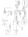
Figure 2 is a block flow diagram of the improved continuous ink jet
ink recirculation system of the present invention, having regulated pressure
sources.
-
Figure 3 is a block flow diagram of an alternative embodiment of
the ink recirculation system of the present invention under atmospheric pressure
and using in-line pumps.
-
The present description will be directed in particular to elements
forming part of, or cooperating more directly with, apparatus in accordance with
the present invention. It is to be understood that elements not specifically shown
or described may take various forms well known to those skilled in the art.
-
These resins can be used directly if they are of the proper metal ion
form (for example, sodium ion form). Alternatively, they can be converted from
the free acid form to the proper metal ion form by common techniques known in
the industry for performing this conversion. Typically, in this case, a quantity of
free acid form of the resin would be treated with strong base of the proper cation
form, for example sodium hydroxide, to generate the proper form of the resin.
Subsequently, after some use and being exhausted with respect to its further
ability to sequester multivalent metal cations from ink flowing through it, the resin
could be regenerated for re-use by exposing it to a concentrated aqueous solution
containing a salt comprised of the original cation form of the resin as, for example
the chloride salt, followed by washing with clean, deionized water to remove the
excess regenerating salt solution. This is a typical regeneration treatment known
in the industry. It should also be noted that the desirable form of the counterion
(cation) for the ink is not restricted to sodium or other alkali metal cation such as
potassium, or lithium, but may also include ammonium or substituted ammonium
ions, protonated primary, secondary, or tertiary amines, alkaline-earth metal ions,
etc. Hence, selection or preparation of the ion exchange resin is not restricted to
sodium ion.
-
It is understood by those familiar with the art that one cannot use a
cation exchange resin (where the ions being exchanged are positively charged) to
treat so-called cationic dye based inks because dye cations would quickly bind to
the oppositely charged sites on the resin, saturating it, thereby rendering it useless
and or plugged. Conversely, it is also understood that anion exchange resins
could not be used to treat so-called anionic dye based inks for the same reason.
For these same reasons, so-called mixed bed resins could not be used with ionic
dye based inks. However, for inks containing neutral, uncharged dye species, any
charge on the ion-exchange resin would be acceptable.
-
It is further understood that inks containing colored or non-colored
colloids can be used in this invention. Colloids may include inorganic oxides such
as silicas or aluminas, natural and man-made clays, colored pigments, polymeric
particles, and colored polymeric particles. Inks containing colloids may contain
charged or uncharged stabilizers or additives. Charged inks containing colloids
require the same considerations regarding the choice of ion-exchange types as for
charged dye based inks.
-
Ions that can cause problems with normal nozzle operation include
multivalent metal cations such as, but not limited to, calcium, barium, zinc,
strontium, magnesium, iron (III), and nickel. These are continually removed from
the ink stream by the use of cation exchange resins specific to those contaminants.
-
Also, multivalent cations are removed from the inks by chelating
resins, including but not limited to chelating resin such as Amberlite IRC-718 .
-
The ion-exchange functionality is integrally incorporated into a
resin matrix that can be of several types, including but not limited to agarose,
cellulose, dextran, methacrylate, polyacrylic and polystyrene.
-
Commercially available cation exchange resins based on agarose
include CM Sepharose CL-6B, CM Sepharose Fast Flow, SP Sepharose Fast
Flow, and SP Sepharose High Performance. Examples of cation exchange resins
that are based on cellulose include CM Cellulose and Cellulose Phosphate.
Examples of cation exchange resins that are based nn dextran include CM
Sephadex C-25, CM Sephadex C-50, SP Sephadex C-25, and SP Sephadex C-50.
-
Especially useful cation exchange resins that are based on either
polystyrene or polyacrylic copolymer include Amberlite 200, Amberlite IR-120
Plus (H), Dowex 50WX4, Dowex HGR-W2, Dowex 650C, Dowex M31, Dowex
HCR-W2 (sodium form), Dowex HCR-W2 (H form), Amberlite IRC-50,
Amberlite GC-50, Amberlite DP-1, Dowex MAC-3, and Dianion WK-100.
-
Additional examples of commercially available chelating resins
that can be used along with or in place of Amberlite IRC-718, are Dianion CR20,
Dowex M-4195, and Duolite C-467. It is understood that this list is not complete
and other commercially available resins of this type would also be useful.
-
The present description will be directed, in particular, to elements
forming part of or cooperating directly with, apparatus or processes of the present
invention. It is to be understood that elements not specifically shown or described
may take various forms well known to those skilled in the art.
-
Referring now to Figure 2, an ion-exchange column (10) is inserted
into the continuous ink recirculation loop, downstream from collection containers
(3 and 4) and upstream from the ink supply reservoir (13), as substantially shown
and described. From nozzles within print head (16), continuous streams of ink are
ejected and heat is applied to the ink stream, for example, by heaters within the
nozzles, heaters positioned on a surface of printhead 16, etc. The ink is thermally
steered into the "print-mode" direction (2) onto a print medium (19).
Alternatively, continuous streams of ink can be thermally steered in the "non-print
mode" direction into a gutter (17), which empties the ink (1) preferably into a first
collection container (3). The ink from said first collection container (3) empties
into a second collection container (4) in controlled fashion. The properties of the
unused ink (1) contained in the second collection container (4) are monitored by
fluid monitoring system (18).
-
One ink property that may be monitored at (18) is dye
concentration. The possible containers that could be needed for controlling dye
concentration are shown as concentrated ink (predominantly dye) (6) and clear
"make-up" fluid (predominantly solvent vehicle) (7), which are added to bottle (4)
via pumps (21) and (22), respectively, if needed. Level sensor (5) is used to detect
fluid levels in the container (4) so that the proper flow of ink throughout the
system can be maintained. This ink monitoring and reconditioning is done to
bring the ink back to the desired properties for optimal printer function. Other
properties of the ink may be monitored and reconditioned as needed. Such
properties include, but are not limited to, viscosity, surface tension, pH, solvent-to-cosolvent
ratio, etc.
-
Ink mixture (8) flowing out of the collection container (4) is
filtered through 9(a) and undesired ions and trace metal contaminants are trapped
in an ion-exchange column resin bed (10) prior to flowing downstream as ink
stream (11).
-
It is understood by those conversant in the art that the ion-exchange
resin will gradually become saturated with contaminant ions as ink flows through
the system. The ion-exchange resin bed in column (10) preferably allows
attendant ion-exchange reactions to go to completion, although it must be kept in
mind that the reactions are intrinsically reversible. Accordingly, the ion-exchange
resin beds may be regenerated by either same-direction flow or reverse flow of a
regenerating solution containing ions of the type that were originally on the
column when it was freshly installed. This process displaces the collected,
undesirable ions such as, but not limited to, multivalent metal cations such as, but
not limited to, calcium, barium, zinc, strontium, magnesium, iron (III), and nickel,
etc. to waste and restores the column to original condition, ready to be reused.
Alternatively, the column may be emptied of its spent resin contents and new resin
introduced. Normally, the regenerated resin would be washed further with
ionically pure water to wash away excess regenerating ionic solution.
-
In accordance with the invention, the undesirable ions are replaced
with the desired cationic species by ion-exchange, involving passing the ink
through a strong acid ion exchange resin which as been treated with an excess of
alkali metals, alkaline-earth metals, quaternary amines, protonated primary,
secondary, or tertiary amines and ammonium ions.
-
Ion-exchange columns of the present invention are sized
sufficiently to fit within the ink recirculation portion of a printer. The resin is held
in a column whose shape may vary depending on application. This variation in
shape of the container may extend to also to its size, and its flow characteristics.
The column contains enough resin to exchange the approximate amount of
adventitious contaminating materials for a reasonable period of time.
-
Useful shapes and designs for the ion-exchange column are
numerous. There is the usual cylindrical chamber filled with ion-exchange media.
One can also employ a chamber consisting of one or more tubes (0.1 to 100
µ diameter, for example) with ion-exchange resin coated on the interior walls of
the tubes. Flow characteristics through this tubing allows intimate contact of ink
with ion- exchangeable sites on the interior tube walls, thereby removing
undesirable ions.
-
Also one or more of the filters in the system can include an
ion-exchange resin so as to consolidate the tasks which are more typically
achieved by a separate filter and resin container or column.
-
Ion-exchange resins may be provided as thin sheets, or membranes,
made strong and flexible and yet permeable. Ion-exchange membranes are often
difficult to obtain with the requisite strength and flexibility while maintaining the
desired permeability, however the membranes can be fabricated, if desired, to
determined specifications.
-
Ink stream (11) is further filtered at 9(b) and the filtered and
ion-exchange treated ink stream (12) flows into a pressure regulated (23) ink
supply reservoir (13). As the printer operates, ink (14) flows from the reservoir
(13) through filter (15) and into print head (16) and the entire cycle as previously
described repeats itself, after ejection from the nozzles of print head (16) until the
printer is turned off. It is noted that the filters 9(a) and 9(b) can also be integrally
incorporated within the ion-exchange station 10.
-
It is to be noted that Figure 2 illustrates a vacuum system having a
source 1 (23) and a source 2 (20) where the vacuum pressure is regulated. This
system pulls the guttered ink (1) into the first collection container (3) and the ink
(12) from filter 9(b) is pulled into ink supply reservoir (13) by the regulated
source (23). The only pumps are (21) and (22) for reconstituting evaporated ink
base by adding concentrate 6 or clear make-up solvent (7) respectively.
-
An alternative system is shown at Figure 3 where regulated
pressure source (20) of Figure 2 is replaced by atmospheric pressure (20) and
regulated source (23) of Figure 2 is removed. They are replaced by a pump Pb just
down stream from the reservoir (13), and a pump Pa just up stream from filter
9(a). Thus the atmospheric pressure pump system of Figure 3 alternatively
powers the fluid through the recirculation process, rather than using regulated
vacuum to pull the stream through the recirculation process of Figure 2. Other
alternative means for forcing the ink through the system can be any combination
of externally applied pressure, or individual pumps as can be readily envisioned
by those skilled in the art.
-
The throughput of such a recycling system must be appropriate for
the continuous operation of the print head. In particular, the size and flow rate of
ink through the ion-exchange column (10) must be high enough to maintain
system operation. The number and size of the nozzles of a print head can vary
widely depending on the application. Flow rates from as low as 1x10⁻⁷ liters per
second to as high as 0.1 liters per second can be employed while still maintaining
system operation, depending on the number and size of the nozzles. Also, the
number of times on average that a particular volume of ink is recirculated through
the system before it is actually printed on a receiving medium can vary widely
depending on the amount of printing being done. This number can vary from as
little as one time to 1000 or more times. These factors must be considered when
determining the quantity, and hence capacity, of ion-exchange resin.
-
It should be noted that although this invention has been described
in terms of its most preferred embodiment which employs heat for either ink drop
formation or for purposes of ink drop deflection, the invention is also intended to
encompass other systems which experience kogation, corrosion, trace metal ion
accumulation, etc. Additionally, the invention is also intended to encompass other
systems that incorporate applying heat to ink.