EP1214609B1 - 3d imaging system - Google Patents
3d imaging system Download PDFInfo
- Publication number
- EP1214609B1 EP1214609B1 EP99943193A EP99943193A EP1214609B1 EP 1214609 B1 EP1214609 B1 EP 1214609B1 EP 99943193 A EP99943193 A EP 99943193A EP 99943193 A EP99943193 A EP 99943193A EP 1214609 B1 EP1214609 B1 EP 1214609B1
- Authority
- EP
- European Patent Office
- Prior art keywords
- light
- camera
- optical imaging
- imaging system
- taking lens
- Prior art date
- Legal status (The legal status is an assumption and is not a legal conclusion. Google has not performed a legal analysis and makes no representation as to the accuracy of the status listed.)
- Expired - Lifetime
Links
Images


Classifications
-
- H—ELECTRICITY
- H04—ELECTRIC COMMUNICATION TECHNIQUE
- H04N—PICTORIAL COMMUNICATION, e.g. TELEVISION
- H04N5/00—Details of television systems
- H04N5/222—Studio circuitry; Studio devices; Studio equipment
- H04N5/2224—Studio circuitry; Studio devices; Studio equipment related to virtual studio applications
- H04N5/2226—Determination of depth image, e.g. for foreground/background separation
-
- G—PHYSICS
- G01—MEASURING; TESTING
- G01S—RADIO DIRECTION-FINDING; RADIO NAVIGATION; DETERMINING DISTANCE OR VELOCITY BY USE OF RADIO WAVES; LOCATING OR PRESENCE-DETECTING BY USE OF THE REFLECTION OR RERADIATION OF RADIO WAVES; ANALOGOUS ARRANGEMENTS USING OTHER WAVES
- G01S17/00—Systems using the reflection or reradiation of electromagnetic waves other than radio waves, e.g. lidar systems
- G01S17/02—Systems using the reflection of electromagnetic waves other than radio waves
- G01S17/06—Systems determining position data of a target
- G01S17/08—Systems determining position data of a target for measuring distance only
- G01S17/10—Systems determining position data of a target for measuring distance only using transmission of interrupted, pulse-modulated waves
- G01S17/18—Systems determining position data of a target for measuring distance only using transmission of interrupted, pulse-modulated waves wherein range gates are used
-
- G—PHYSICS
- G01—MEASURING; TESTING
- G01S—RADIO DIRECTION-FINDING; RADIO NAVIGATION; DETERMINING DISTANCE OR VELOCITY BY USE OF RADIO WAVES; LOCATING OR PRESENCE-DETECTING BY USE OF THE REFLECTION OR RERADIATION OF RADIO WAVES; ANALOGOUS ARRANGEMENTS USING OTHER WAVES
- G01S17/00—Systems using the reflection or reradiation of electromagnetic waves other than radio waves, e.g. lidar systems
- G01S17/86—Combinations of lidar systems with systems other than lidar, radar or sonar, e.g. with direction finders
-
- G—PHYSICS
- G01—MEASURING; TESTING
- G01S—RADIO DIRECTION-FINDING; RADIO NAVIGATION; DETERMINING DISTANCE OR VELOCITY BY USE OF RADIO WAVES; LOCATING OR PRESENCE-DETECTING BY USE OF THE REFLECTION OR RERADIATION OF RADIO WAVES; ANALOGOUS ARRANGEMENTS USING OTHER WAVES
- G01S17/00—Systems using the reflection or reradiation of electromagnetic waves other than radio waves, e.g. lidar systems
- G01S17/88—Lidar systems specially adapted for specific applications
- G01S17/89—Lidar systems specially adapted for specific applications for mapping or imaging
- G01S17/894—3D imaging with simultaneous measurement of time-of-flight at a 2D array of receiver pixels, e.g. time-of-flight cameras or flash lidar
-
- G—PHYSICS
- G01—MEASURING; TESTING
- G01S—RADIO DIRECTION-FINDING; RADIO NAVIGATION; DETERMINING DISTANCE OR VELOCITY BY USE OF RADIO WAVES; LOCATING OR PRESENCE-DETECTING BY USE OF THE REFLECTION OR RERADIATION OF RADIO WAVES; ANALOGOUS ARRANGEMENTS USING OTHER WAVES
- G01S7/00—Details of systems according to groups G01S13/00, G01S15/00, G01S17/00
- G01S7/48—Details of systems according to groups G01S13/00, G01S15/00, G01S17/00 of systems according to group G01S17/00
- G01S7/481—Constructional features, e.g. arrangements of optical elements
- G01S7/4811—Constructional features, e.g. arrangements of optical elements common to transmitter and receiver
- G01S7/4812—Constructional features, e.g. arrangements of optical elements common to transmitter and receiver transmitted and received beams following a coaxial path
Landscapes
- Engineering & Computer Science (AREA)
- Physics & Mathematics (AREA)
- Radar, Positioning & Navigation (AREA)
- Remote Sensing (AREA)
- Electromagnetism (AREA)
- General Physics & Mathematics (AREA)
- Computer Networks & Wireless Communication (AREA)
- Computer Vision & Pattern Recognition (AREA)
- Multimedia (AREA)
- Signal Processing (AREA)
- Testing, Inspecting, Measuring Of Stereoscopic Televisions And Televisions (AREA)
- Apparatus For Radiation Diagnosis (AREA)
- Studio Devices (AREA)
- Ultra Sonic Daignosis Equipment (AREA)
Abstract
Description
- The invention relates to cameras that provide an image of a scene and measurements of distances to regions in the scene.
- 3D cameras that provide distance measurements to objects and points on objects that they image are well known in the art. Gated 3D cameras comprise a photosensitive surface, such as a CCD or CMOS camera, hereinafter referred to as a "photosurface", and a gating means for gating the camera open and closed, such as an electro-optical shutter or a gated image intensifier. To image a scene and determine distances from the camera to objects in the scene, the scene is generally illuminated with a train of light pulses radiated from an appropriate light source. Generally, the radiated light pulses are infrared (IR) light pulses. For each radiated light pulse in the train, following an accurately determined delay from the time that the light pulse is radiated, the camera is gated open for a period of time, hereinafter referred to as a "gate". Light from the light pulse that is reflected from an object in the scene is imaged on the photosurface of the camera if it reaches the camera during the gate. Since the time elapsed between radiating a light pulse and the gate that follows it is known, the time it took imaged light to travel from the light source to the reflecting object in the scene and back to the camera is known. The time elapsed is used to determine the distance to the object.
- In some of these 3D cameras, only the timing between light pulses and gates is used to determine distance from the 3D camera to a region in the scene imaged on a pixel of the photosurface of the 3D camera. In others, the amount of light registered by the pixel during the time that the camera is gated open is also used to determine the distance. In 3D cameras in which the amount of light is used to determine distances to the imaged region, the amount of light registered on a pixel is sometimes corrected for reflectivity of the imaged region, dark current and background light. The accuracy of measurements made with these 3D cameras is a function of the rise and fall times and jitter of the light pulses and their flatness, and how fast the gating means can gate the camera open and closed.
- Gated 3D cameras that determine distances to objects in a scene that they image responsive to amounts of light registered on pixels of photosurfaces comprised in the 3D cameras are described in PCT Publications WO 97/01111, WO 97/01112, and WO 97/01113.
- A gated 3D camera as shown in WO 97/01111 comprises first and second homologous photosurfaces and a light source that illuminates a scene being imaged with the camera with a train of, preferably IR, light pulses. The first photosurface, hereinafter referred to as a "distance photosurface", is gated on with a short gate following the time that each light pulse in the pulse train is radiated. The portion of light from each light pulse in the pulse train that is reflected by a region of the scene and enters the 3D camera, which is registered on a pixel of the distance photosurface, is a function of the distance of the region from the pixel. The second photosurface, hereinafter referred to as a "normalization photosurface", is preferably not gated. The portion of light from each light pulse in the pulse train that is reflected by a region of the scene and enters the 3D camera, which is registered on a pixel of the normalization photosurface, is independent of the distance of the region from the pixel. The amount of light registered on the pixel is a measure of the total amount of light reaching the camera from the imaged region. An amount of reflected light registered on a pixel of the distance photosurface from all the light pulses in the pulse train is normalized to an amount of reflected light from all the light pulses registered on a corresponding pixel in the normalization photosurface. Normalized amounts of light are used to determine distances to regions in the scene.
- US patent 5,434,6I2 to Nettleton, describes a gated 3D camera comprising first, second and third photosurfaces. A scene imaged with this camera is not illuminated with a train of light pulses but with a single light pulse from a laser and the three photosurfaces are gated with respect to the time that the light pulse is radiated. The first photosurface is a distance photosurface. It is gated with a short gate so that a portion of the light pulse reflected by a region of the scene that is collected by the camera and registered on a pixel of the photosurface is a function of the distance of the region from the pixel. The second photosurface is a normalization photosurface. It is gated with a long gate so that the amount of reflected laser light registered on a pixel of the photosurface from an imaged region is a measure of the total amount of light reaching the camera from the imaged region. The third photosurface is used to measure background light by measuring the amount of light reaching the camera in a band of wavelengths near to wavelengths of light radiated by the laser. A filter that transmits light in the band of wavelengths close to the wavelength of the laser light but blocks light having a wavelength the same as a wavelength of light radiated by the laser shields the third photosurface. The third photosurface is gated simultaneously with the normalization photosurface by a long gate having a same gate width as the gate that gates the second photosurface. A photosurface used to measure background light is hereinafter referred to as a "background photosurface".
- Amounts of light registered on the background photosurface are used to correct the amounts of light registered on pixels of the distance and normalization photosurfaces for background light. Background corrected amounts of light registered by pixels on the normalization photosurface are used to normalize background corrected amounts of light registered by pixels on the distance photosurface. Distances to regions in the scene are determined from the background corrected normalized amounts of light registered by pixels on the distance photosurface.
- Generally photosurfaces used in 3D cameras are gated by an external fast shutter. Certain types of CCD cameras allow for gating image acquisition on and off during a frame by turning the photosurfaces on and off. However, turn-on and turn-off times of these photosurfaces are generally much too long to enable gating the photosurfaces for the purposes of accurate distance measurements by turning them on and off. Typically turn-on and tum-off times for CCD photosurfaces are on the order of microseconds while gating for accurate distance measurements requires turn-on and turn-off times on the order of nano-seconds or less.
- An electro-optical shutter suitable for use in 3D cameras, such as those described in the cited patent and patent applications is described in PCT Publication WO 99/40478.
- Generally, a 3D camera is used in conjunction with an imaging camera, such as a video camera, that provides an image, hereinafter referred to as a "picture", of a scene being imaged with the 3D camera responsive to visible light from the scene. The 3D camera provides a "depth map" of the scene while the imaging camera provides a picture of the scene. Distances provided by the depth map are associated with visible features in the picture. In some applications distances associated with a picture of a scene are used to "window" the scene and remove unwanted features and/or objects in the scene, such as for example a background, from the picture. Such applications are described in PCT publication in WO 97/01111 cited above.
- PCT patent application PCT/IL98/00476, entitled "Distance Measurement with a Camera", by some of the same inventors as the inventors of the present invention, describes a photosurface comprising pixels each of which has its own circuit that is controllable to gate the pixel on or off. A single photosurface of this type is useable to simultaneously provide the functions of a distance, background and normalization photosurface of a 3D camera as well as an imaging camera. However, as the number of functions that the photosurface performs increases, the resolution of the photosurface decreases.
- It is advantageous to have a simple robust optical system comprising a 3D camera and an imaging camera that is easily adjustable to simultaneously optimize quantities of light available from a scene imaged by the system that reach the cameras.
- An aspect of some preferred embodiments of the present invention relates to providing an improved optical system, hereinafter referred to as a "3D imager", comprising a 3D camera and an imaging camera, for acquiring depth maps and pictures of a scene.
- An aspect of some preferred embodiments of the present invention relates to providing a 3D imager that is relatively easily adjusted so that its 3D and imaging cameras may simultaneously receive optimum amounts of light available from a scene being imaged with the 3D imager.
- An aspect of some preferred embodiments of the present invention relates to providing a 3D imager comprising an improved gating system for gating photosurfaces comprised in its 3D camera.
- A 3D imager, in accordance with some preferred embodiments of the present invention, comprises a single taking lens boresighted with a gated 3D camera and an imaging camera. Preferably, the imaging camera is a color camera. Preferably the 3D camera comprises three photosensitive surfaces, a distance photosurface, a normalization photosurface and a background photosurface. Preferably, the 3D imager is used with a pulsed IR light source that illuminates a scene being imaged with the 3D imager with a train of preferably IR, light pulses. Light from the light pulses reflected by objects in the scene is used by the 3D camera to provide a depth map of the scene. Visual light from the scene is used by the imaging camera to provide a picture of the scene
- While there is usually more than ample amount of visible light available to form a quality picture of the scene, the quantity of light available for the purpose of providing a depth map of the scene is usually small. As a result, the 3D imager usually requires that the taking lens be set to a much higher f-number to produce a quality picture of the scene than an f-number required to provide accurate distance measurements to the scene.
- To provide proper control of the amounts of light reaching the 3D camera and the imaging camera, the 3D imager comprises a system that controls the amount of light reaching the imaging camera from the taking lens independently of the amount of light reaching the 3D camera.
- Preferably, the 3D camera comprises at least two irises. A first iris of the at least two irises controls the amount of visible light collected by the taking lens that reaches the imaging camera. A second iris controls either the amount of IR light collected by the taking lens that reaches the 3D camera or the total amount of IR and visible light collected by the taking lens that enters the 3D imager. As a result, the 3D imager can be adjusted to control independently amounts of light reaching the imaging camera and the 3D camera from a scene being imaged with the 3D imager. Therefore, subject to a level of illumination of the scene, a 3D imager, in accordance with a preferred embodiment of the present invention, is adjustable to simultaneously optimize the amounts of light from the scene that reach its 3D and imaging cameras.
- In accordance with some preferred embodiments of the present invention all photosurfaces comprised in the 3D camera are gated with a same single fast shutter. This substantially simplifies the construction and control of the 3D imager. Preferably the 3D camera comprises three photosurfaces, a distance photosurface, a background photosurface and a normalization photosurface. The three photosurfaces are independently controllable to be turned on and off. Preferably, all light transmitted from the taking lens to the 3D camera passes through the single fast shutter. After passing through the shutter, portions of the light are directed to each of the three photosurfaces, for example by a prism. Preferably, the prism is a totally internal reflection (TIR) prism. At any given time, to determine which of the photosurfaces is gated by the fast shutter, all photosurfaces except a photosurface that is to be gated by the fast shutter are shut off.
- It is to be noted that whereas the photosurfaces are controllable to be turned on or off, the speed with which a photosurface can be switched between on and off states is generally not fast enough to gate the photosurfaces for the purposes of accurate distance measurements. Therefore, for 3D cameras, gating photosurfaces by turning them on and off is generally not practical.
- In some preferred embodiments of the present invention, the 3D camera and associated optical components are housed as a single unit, hereinafter referred to as a "3D module". The 3D module comprises portals for optically coupling a taking lens and imaging camera to the 3D module using methods and techniques known in the art. In some preferred embodiments of the present invention, the 3D camera, imaging camera and associated electrical and optical components are integrated together as a single unit to which a taking lens is optically coupled.
- There is therefore provided, in accordance with a preferred embodiment of the present invention an optical imaging system comprising: a taking lens system that collects light from a scene being imaged with the optical imaging system; a 3D camera comprising at least one photosurface that receives light from the taking lens system simultaneously from all points in the scene and provides data for generating a depth map of the scene responsive to the light; and an imaging camera comprising at least one photosurface that receives light from the taking lens system and provides a picture of the scene responsive to the light.
- Preferably, the 3D camera and the imaging camera are boresighted with the taking lens system. Additionally or alternatively, the at least one photosurface of the 3D camera and the at least one photosurface of the imaging camera are preferably homologous.
- In some preferred embodiments of the present invention, an optical imaging system comprises a light controller adjustable to control the amount of light from the taking lens system that reaches the imaging camera without affecting the amount of light from the taking lens system that reaches the 3D camera. Preferably, the light controller comprises an iris. Alternatively, the light controller preferably comprises a neutral density filter.
- In some preferred embodiments of the present invention, an optical imaging system comprises a light controller adjustable to control the amount of light collected by the taking lens system that enters the imaging system. Preferably, the light controller comprises an iris.
- In some preferred embodiments of the present invention, an optical imaging system comprises a light controller adjustable to control the amount of light from the taking lens system that reaches the 3D camera without affecting the amount of light from the taking lens that reaches the imaging camera. Preferably, the light controller comprises an iris.
- The 3D camera in an optical imaging system in accordance with some preferred embodiment of the present invention is a gated 3D camera. Preferably, the optical imaging system comprises a pulsed light source that radiates a train of light pulses to illuminate a scene being imaged with the optical imaging system. Preferably, the pulsed light source radiates IR light.
- According to some preferred embodiments of the present invention, the 3D camera comprises at least 2 photosurfaces. Preferably, the 3D camera comprises a light guide that receives light from the taking lens system and directs portions of the light that it receives to each of the at least two photosurfaces. Preferably, the 3D camera comprises a single shutter, which when gated open enables light from the taking lens system to reach the light guide.
- The optical imaging system preferably comprises a controller that gates the single shutter open and closed. Preferably, the controller controls each of the photosurfaces to be activated and deactivated and wherein when a photosurface is activated, it is sensitive to light incident thereon. Preferably, the controller gates on the single shutter it activates one and only one of the at least two photosurfaces.
- Preferably, the at least two photosurfaces comprises three photosurfaces. Preferably, following a time that at least one light pulse is radiated, the controller gates on the single shutter for a first gate and turns on a first photosurface and the first gate is timed so that light reflected from the at least one light pulse by a region in the scene is registered by the first photosurface.
- Following a time that at least one light pulse in the train of light pulses is radiated, the controller preferably gates on the single shutter for a second gate and activates a second one of the photosurfaces and the second gate is timed so that during the second gate no light from the at least one light pulse reflected by the region is registered by the second photosurface.
- Prefeably, following a time that at least one light pulse in the train of light pulses is radiated the controller gates on the single shutter for a third gate and activates a third one of the photosurfaces and the controller controls the gate width and timing of the third gate so that during the third gate substantially all light from the at least one pulse that is reflected by the region, which is collected by the taking lens system, is registered by the third photosurface.
- In some preferred embodiments of the present invention the light guide of the 3D camera is a three-way prism.
- Some optical imaging systems in accordance with preferred embodiments of the present invention comprise a beam splitter that receives light from the taking lens system and directs a portion of the received light towards the 3D camera and a portion of the received light to the imaging camera.
- In some preferred embodiments of the present invention the light guide of the 3D camera is a four-way prism that receives light from the taking lens system and directs a portion of the received light to the imaging camera.
- In some preferred embodiments of the present invention the imaging camera comprises a color camera.
- In some optical imaging systems, in accordance with preferred embodiments of the present invention, the imaging camera is a color camera comprising separate R, G and B photosurfaces and the imaging system comprises a four way prism that receives light from the taking lens system and directs a portion of the received light to each of the R, G and B photosurfaces and to the single shutter of the 3D camera.
- There is further provided in accordance with a preferred embodiment of the present invention a gated 3D camera comprising: a taking lens system that collects light from a scene imaged with the 3D camera; at least 2 photosurfaces; a light guide that receives light from the taking lens and directs portions of the light that it receives to each of the at least two photosurfaces; and a single shutter, which when gated open enables light from the taking lens system to reach the light guide.
- Preferably, the controller controls each of the photosurfaces to be activated and deactivated and wherein when a photosurface is activated, it is sensitive to light incident thereon. Preferably, each time that the controller gates on the single shutter it activates one and only one of the at least two photosurfaces. Preferably, the at least two photosurfaces comprises three photosurfaces.
- The 3D camera preferably comprises a pulsed light source that radiates a train of light pulses to illuminate a scene being imaged with the 3D camera. Prefereably, following a time that at least one light pulse is radiated, the controller gates on the single shutter for a first gate and turns on a first photosurface and the first gate is timed so that light reflected from the at least one light pulse by a region in the scene is registered by the first photosurface.
- Preferably, following a time that at least one light pulse in the train of light pulses is radiated, the controller gates on the single shutter for a second gate and activates a second one of the photosurfaces and the second gate is timed so that during the second gate no light from the at least one light pulse reflected by the region is registered by the second photosurface.
- Preferably, following a time that at least one light pulse in the train of light pulses is radiated, the controller gates on the single shutter for a third gate and activates a third one of the photosurfaces and the controller controls the gate width and timing of the third gate so that during the third gate substantially all light from the at least one pulse that is reflected by the region, which is collected by the taking lens system, is registered by the third photosurface.
- The invention will be more clearly understood by reference to the following description of preferred embodiments thereof read in conjunction with the figures attached hereto. In the figures, identical structures, elements or parts which appear in more than one figure are labeled with the same numeral in all the figures in which they appear. Dimensions of components and features shown in the figures are chosen for convenience and clarity of presentation and are not necessarily shown to scale. The figures are listed below.
- Fig. 1 schematically shows a 3D imager comprising a 3D module, in accordance with a preferred embodiment of the present invention;
- Fig. 2A schematically shows a 3D imager comprising a 3D module, in accordance with a preferred embodiment of the present invention;
- Fig. 2B shows a timing diagram for shuttering photosurfaces comprised in the 3D imager shown in Fig. 2A, in accordance with a preferred embodiment of the present invention;
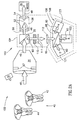
- Fig. 3 schematically shows a 3D imager comprising a 3D module, in accordance with a preferred embodiment of the present invention; and
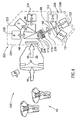
- Fig. 4 schematically shows a 3D imager comprising a 3D module and color imager integrated in a single unit, in accordance with a preferred embodiment of the present invention.
-
- Fig. 1 schematically shows a
3D imager 20 comprising a3D module 22, in accordance with a preferred embodiment of the present invention, shown inside dashedboundary 24.3D module 22 comprises abeam splitter 26, two refocusinglens systems 3D camera 32 having components shown inside a dashedboundary 34.3D module 22 is coupled to a takinglens system 35 and animaging camera 36, which is shown by way of example as a video camera. Preferably,video camera 36 is a color video camera. Takinglens 35 andvideo camera 36 may be any suitable taking lens and video camera, for example a CCD or CMOS camera, readily available on the commercial market. A pulsedlight source 38 radiates pulse trains of, preferably IR light pulses, to illuminate scenes being imaged with3D imager 20.3D imager 20 is shown, by way of example, imaging ascene 40 having twoelephants - Visual light and IR light from
IR source 38 that is reflected fromscene 40 and collected by takinglens 35 is represented bylarge arrows 46.Collected light 46 is transmitted by takinglens 35 tobeam splitter 26. Visual light, represented byarrows 48, in collected light 46, is transmitted bybeam splitter 26 and entersrefocuser 28.Refocuser 28 generally comprises afield lens 50, aniris 52 and arelay lens 54.Refocuser 28 is boresighted with takinglens 35 and preferably positioned so that an image ofscene 40 formed by takinglens 35 fromvisual light 48 is located substantially at the location offield lens 50. Light fromfield lens 50 passes throughiris 52 and continues towardsrelay lens 54, which transmits the light tovideo camera 36.Video camera 36 is boresighted withrefocuser 28 and takinglens 35. The amount of light received byvideo 36 fromrefocuser 28 is controlled byiris 52. Receivedvisual light 48 is imaged byvideo 36 to form a picture ofscene 40. - IR light, represented by dashed
arrows 60, in collected light 46 that is incident onbeam splitter 26 is reflected bybeam splitter 26 torefocuser 30, which is boresighted with takinglens 35.Refocuser 30 is generally similar torefocuser 28 and preferably comprises afield lens 62, aniris 64 and a relay lens 66.Refocuser 30 is preferably positioned so that an image ofscene 40 formed inIR light 60 by takinglens 35 is located at the location offield lens 62.Refocuser 30 transmits IR light that it receives towards3D camera 32 which is boresighted withrefocuser 30 and takinglens 35. The amount of IR light 60 transmitted byrefocuser 30 to3D camera 32 is controlled byiris 64. -
Irises 3D camera 32 andvideo camera 36 respectively to be controlled independently of each other, in accordance with a preferred embodiment of the present invention.3D imager 20 therefore can easily be adjusted to simultaneously optimize the amounts of IR light reaching3D camera 32 and visual light reachingvideo camera 36 from takinglens 35 to provide simultaneous quality depth maps and pictures ofscene 40. - It is to be noted that commercially available taking lenses are generally supplied with an iris and taking
lens 35 is shown with aniris 67. In operation of3D imager 20,iris 67 is preferably permanently set to maximum open and the amounts of light reaching3D camera 32 andvideo camera 36 are controlled byirises present invention iris 67 is used in place of one ofirises lens 35 is needed to produce a quality depth map of a scene than the fraction that is needed of visible light collected by takinglens 35 to provide a quality picture of the scene. As a result,iris 67 may conveniently be used in place ofiris 64 to modulate IR light reaching3D camera 32. -
3D camera 32 preferably comprises a three-way prism 68 and preferably threephotosurfaces way prism 68 receives IR light 60 transmitted fromrefocuser 30 and directs portions of the received IR light to each ofphotosurfaces Photosurfaces fast shutters Fast shutters shutters -
Photosurfaces shutters gate photosurfaces IR source 38 with a sequence of gates similar to prior art gate sequences used in gated 3D cameras. Prior art gating sequences are described in above cited references PCT Publications WO 97/01111, WO 97/01112, WO 97/01113, US Patent 5,434,612 and PCT Application PCT/IL98/00476. - Whereas, in the preceding paragraph it is implied that photosurfaces 71, 72 and 73 are similar or substantially identical, and this is generally the case, in some preferred embodiments of the present invention, different ones of the photosurfaces in
3D camera 32 are different. For example, a photosurface used to measure background light or normalization light may have a lower resolution than a resolution of a photosurface used as a distance photosurface and this can be advantageous. -
Shutter 81 is controlled to respectivelygate distance photosurface 71 with a relatively short gate andnormalization photosurface 73 with a relatively long gate. Preferably the short gate has a gate width that is equal to the pulse width of IR pulses radiated bypulsed IR source 38. Preferably the time centers of the short gates and long gates coincide. The controller preferably controls shutter 83 togate background photosurface 72 with a short gate. The short gate ofbackground photosurface 72 is timed to occur when no IR light frompulsed IR source 38 that is reflected fromscene 40 is incident on takinglens 35. Preferably the short gates ofdistance photosurface 71 andbackground photosurface 72 are equal. During the short gate ofbackground photosurface 72, substantially only background light and dark current effects are registered bybackground photosurface 72. - The amounts of light registered on pixels of
distance photosurface 71,background photosurface 72 andnormalization photosurface 73 are sensed and transmitted to a processor (not shown) using methods known in the art and processed as in prior art to provide a depth map ofscene 40. - Photosurfaces comprised in 3D cameras and imaging cameras that are used in 3D imagers, in accordance with preferred embodiments of the present invention, are preferably homologous. Two photosurfaces are said to be homologous if there is a one to one mapping of regions of one of the photosurfaces onto the other and the positions of any two regions that map onto each other are similar in their respective photosurfaces.
- Fig. 2 shows another
3D imager 100imaging scene 40.3D imager 100 comprises a3D module 102 optically coupled to takinglens 35 andvideo camera 36. -
3D module 102, having components shown inside dashedboundary 104, is similar to3D module 22.3D module 102 comprisesbeam splitter 26 andrefocuser 28 that transmits visual light 48 from takinglens 35 tovideo camera 36, which generates a picture ofscene 40 responsive to the visual light that it receives.3D module 102 comprises a3D camera 106 having components shown inside dashedboundary 108. - However, unlike
3D module 22,3D module 22 does not comprise arefocuser 30 that irises and transmits IR light frombeam splitter 26 to3D camera 106. Instead, IR light 60 frombeam splitter 26 passes through afast shutter 110 and arelay lens 112 that directs the IR light to3D camera 106. Preferably, aniris 111 controls the amount of light from takinglens 35 transmitted to3D camera 106.3D camera 106 is similar to3D camera 32 shown in Fig. 1 and comprises a three-way prism 68 that directs portions of IR light 60 incident on three-way prism 68 to adistance photosurface 121, abackground photosurface 122 and anormalization photosurface 123. However, unlikephotosurfaces 3D camera 32,Photosurfaces 3D camera 32. Fast gating for allphotosurfaces fast shutter 110, which is common to allphotosurfaces Photosurfaces fast shutter 110. Preferably, only one photosurface is turned on during a gate offast shutter 110. -
Fast shutter 110 is controlled by a controller (not shown) to be gated open with a sequence of short and long gates in synchrony with IR pulses radiated byIR source 38. Preferably, two sequential short gates having a same gate width follow every other IR light pulse in a train of light pulses radiated by IRlight source 38 to illuminatescene 40. Preferably, a long gate follows every IR pulse that is not followed by the two sequential short gates. - During the first short gate, IR light reflected from
scene 40 is collected by takinglens 35 and transmitted to3D camera 106 and onlydistance photosurface 121 is turned on.Only distance photosurface 121 registers amounts of light incident on3D camera 106 during the first short gate. The amount of reflected IR light registered ondistance photosurface 121 from a region ofscene 40, compared to the total amount of reflected IR light reaching takinglens 35 from the region is useable to determine the distance of the region from3D camera 106. - The timing of the first short gate with respect to an IR light pulse from which reflected light is registered by distance photosurface 121 and the gate width of the short gate, determine a center for a range of distances for which
3D camera 106 can provide distance measurements to regions inscene 40. The width of the range is determined by the pulse width of the IR pulses and the gate width of the short gate. - The second short gate is timed to occur when no IR light reflected from
scene 40reaches taking lens 35. During the second short gate only background light is collected by takinglens 35 and transmitted to3D camera 106.Only background photosurface 122 is turned on and registers light incident on3D camera 106.Background photosurface 106 exclusively acquires background light information fromscene 40. - The time centers of the long gates and the first short gates are preferably delayed by the same time with respect to their respective IR light pulses. During the long gates, only
normalization photosurface 123 is turned on.Normalization photosurface 123 registers amounts of IR light that are responsive to total amounts of reflected IR light reaching takinglens 35 from regions ofscene 40. - It should be noted that, while
photosurfaces gate 3D camera 106, gating of3D camera 106 for accurate distance measurements cannot be accomplished withoutfast gate 110 and only by turning on and offphotosurfaces photosurfaces - However, whereas turning photosurfaces on and off can not generally be used for fast shuttering of photosurfaces, it can be used for irising photosurfaces. For example, a photosurface in some video cameras can be turned off for a fraction of a frame time to control an amount of light that the photosurface registers. In some preferred embodiments of the present invention irising of an imaging camera is accomplished by controlling the length of time that a photosurface comprised in the imaging camera is on during a frame time.
- As in prior art, amounts of light registered on pixels of
distance photosurface 121 are corrected for background and normalized using amounts of light registered on corresponding pixels of onbackground photosurface 122 andnormalization photosurface 123. The corrected and normalized amounts of light are used to determine distances to reflecting regions ofscene 40, in this case, by way of example distances toelephants - Fig. 2B shows, as function of time, a
graph 130 of gates offast shutter 110 and associated periods of time, hereinafter referred to as "on times" during which photosurfaces 121, 122 and 123 are turned on, in accordance with a preferred embodiment of the present invention. The gates and on times are shown by way of example synchronized with four IR pulses, represented byrectangles time line 136, of a pulse train of IR pulses radiated byIR source 38 shown in Fig. 2A to illuminatescene 40. The choice of four IR pulses in the train of pulses is by way of example only and is a choice of convenience. - The gates of
fast gate 110 are represented by dashedrectangles Gates 141 are short "distance gates" andgates 142 are short "background gates". Adistance gate 141 and abackground gate 142 follow every other IR pulse (the odd numbered IR pulses in Fig. 2B) in the pulse train radiated byIR source 38.Gates 143 are long "normalization" gates that preferably follow every IR pulse (the even numbered IR pulses in Fig. 2B) that is not followed by adistance gate 141 and abackground gate 142. - The on times of distance, background and
normalization photosurfaces trapezoids 150 ontimelines Distance photosurface 121 is on only duringshort distance gates 141.Background photosurface 122 is on only duringshort background gates 142 andnormalization photosurface 123 is on only duringlong normalization gates 143. The sloped side edges of the trapezoids indicate the relatively long periods of time required to turn on and off a photosurface compared to the short turn-on and turn-off times required to gate photosurfaces quickly enough to provide accurate distance measurements. - An intensity of light received by taking
lens 35 fromelephant 42 as a function of time is represented by the height of an "intensity"line 160 above abase line 162. Rectangular "peaks" 164 in the height ofintensity line 160 occur when IR light reflected from an IR pulse byelephant 42reaches taking lens 35. The height ofintensity line 160 outside ofpeaks 164 represents background light received fromelephant 42. Amounts of light received fromelephant 42 that are registered byphotosurfaces gates shaded areas - Similarly, an intensity of light received by taking
lens 35 fromsecond elephant 44 as a function of time is represented by the height of anintensity line 180, which has IR "reflection peaks" 184, above abase line 182.Shaded areas second elephant 44 registered byphotosurfaces gates - For
elephant 42, background corrected light registered bydistance photosurface 121 is represented by an area equal to the sum of theareas 171 minus the sum ofareas 172. Background corrected light registered bynormalization photosurface 123 is represented by an area equal to the sum ofareas 173 minus the product of the ratio of the gate width oflong gates 143 to the gate width ofshort gates 142 times the sum ofareas 173. Forelephant 44, background corrected light registered bydistance photosurface 121 is represented by an area equal to the sum ofareas 181 minus the sum ofareas 182. Background corrected light registered bynormalization photosurface 123 forelephant 44 is represented by an area equal to the sum ofareas 183 minus the product of the ratio of the gate width oflong gates 143 to the gate width ofshort gates 142 times the sum ofareas 183. -
Elephant 44 is further away from3D imager 100 thanelephant 42. As a result, the amount of background corrected light registered bydistance photosurface 121 normalized to background collected light registered bynormalization photosurface 123 is less forelephant 44 than forelephant 42. - Fig. 3 shows another
3D imager 200imaging scene 40, in accordance with a preferred embodiment of the present invention. -
Imager 200 comprises a3D module 202 having components shown inside dashedborder 204, which is coupled to takinglens 35 andvideo camera 36.3D module 202 comprises a3D camera 206 having components shown inside dashedborder 208.3D camera 206 comprises a four-way prism 210 that directs portions of IR light 60 inlight 46 that is collected by takinglens 35 fromscene 40 to distance, background andnormalization photosurfaces photosurfaces fast shutter Photosurfaces 3D camera 206, shown in Fig. 1, are gated. Amounts of IR light 60 collected by takinglens 35 that reaches3D camera 206 is controlled byiris 67 comprised in takinglens 35. - Four-
way prism 210 also directs visual light 48 inlight 46 collected by takinglens 35 to arefocuser 28 that preferably comprises afield lens 50 aniris 52 and arelay lens 54.Refocuser 28 transmits visual light 48 that it receives from four-way prism 210 tovideo camera 36. - Fig. 4 schematically shows another
3D imager 220imaging scene 40 in accordance with a preferred embodiment of the present invention.3D imager 220 comprises aunit 222, hereinafter referred to as a "combination unit", having components located within aborder 224.Combination unit 222 comprises a3D camera 226 having components shown inside a dashed boundary 228 and three color cameras, a Red (R) camera 230 a Green (G)camera 232 and a Blue (B)camera 234.Combination unit 222 is coupled to a takinglens 35, which is boresighted with3D camera 226 andcolor cameras -
Combination unit 222 comprises a four-way prism 236 that directs visual light 48 collected by takinglens 35 to each ofcolor cameras lens 35 to afast shutter 110 thatshutters 3D camera 226. Preferably,combination unit 222 comprises aniris 111 that controls the amount of light 60 transmitted from takinglens 35 to3D camera 226. IR light 60 thatfast shutter 110 transmits is incident on arelay lens 238 that relays the light to a three-way prism 68, which directs portions of the IR light 60 that it receives to adistance photosurface 121, abackground photosurface 122 and anormalization photosurface 123.3D camera 226 is substantially the same as3D camera 106 shown in Fig. 2A and is gated by controllingfast shutter 110 and photo surfaces 121, 122, and 123 in the same manner in which3D camera 106 is gated. - Whereas
combination unit 222 is shown comprising a 3D camera in which all the photosurfaces are shuttered by single shutter, in some preferred embodiments of the present invention,combination unit 222 comprises a 3D camera similar to3D camera 32 shown in Fig. 1 in which each photosurface of the 3D camera is shuttered by its own shutter. -
Combination unit 222 preferably comprises an adjustableneutral density filter 240 located between takinglens 35 and four-way prism 236.Neutral density filter 240 is chosen so that it does not substantially attenuate IR light.Neutral density filter 240 is used to control the amount ofvisible light 48 collected by takinglens 35 that reachescolor cameras 3D camera 226 is controlled byiris 67 comprised in takinglens 35. - In the description and claims of the present application, each of the verbs, "comprise" "include" and "have", and conjugates thereof, are used to indicate that the object or objects of the verb are not necessarily a complete listing of components, elements or parts of the subject or subjects of the verb.
- The present invention has been described using detailed descriptions of preferred embodiments thereof that are provided by way of example and are not intended to limit the scope of the invention. The described preferred embodiments comprise different features, not all of which are required in all embodiments of the invention. Some embodiments of the present invention utilize only some of the features or possible combinations of the features. Variations of embodiments of the present invention that are described and embodiments of the present invention comprising different combinations of features noted in the described embodiments will occur to persons of the art. The scope of the invention is limited only by the following claims.
Claims (28)
- An optical imaging system comprising:a taking lens system that collects light from a scene being imaged with the optical imaging system;a 3D camera comprising at least one photosurface that receives light from the taking lens system simultaneously from all points in the scene and provides data for generating a depth map of the scene responsive to the light; andan imaging camera comprising at least one photosurface that receives light from the taking lens system and provides a picture of the scene responsive to the light; anda light control system that controls an amount of light from the taking lens that reaches at least one of the 3D camera and the imaging camera without affecting an amount of light that reaches the other of the 3D camera and the imaging camera.
- An optical imaging system according to claim 1 wherein the 3D camera and the imaging camera are boresighted with the taking lens system.
- An optical imaging system according to claim 1 or claim 2 wherein the at least one photosurface of the 3D camera and the at least one photosurface of the imaging camera are homologous.
- An optical imaging system according to any of the preceding claims wherein the light control system comprises a light controller adjustable to control the amount of light from the taking lens system that reaches the imaging camera without affecting the amount of light from the taking lens system that reaches the 3D camera.
- An optical imaging system according to claim 4 wherein the light controller comprises an iris.
- An optical imaging system according to claim 4 wherein the light controller comprises a neutral density filter.
- An optical imaging system according to any of the preceding claims wherein the light control system comprises a light controller adjustable to control the amount of light collected by the taking lens system that enters the imaging system.
- An optical imaging system according to claim 7 wherein the light controller that controls the amount of light collected by the taking lens system that enters the imaging system comprises an iris.
- An optical imaging system according to any of the preceding claims and comprising a light controller adjustable to control the amount of light from the taking lens system that reaches the 3D camera without affecting the amount of light from the taking lens that reaches the imaging camera.
- An optical imaging system according to claim 9 wherein the light controller that controls the amount of light from the taking lens system that reaches the 3D camera comprises an iris.
- An optical imaging system according to any of the preceding claims wherein the 3D camera is a gated 3D camera.
- An optical imaging system according to claim 11 and comprising a pulsed light source that radiates a train of light pulses to illuminate a scene being imaged with the optical imaging system.
- An optical imaging system according to claim 12 wherein the pulsed light source radiates IR light.
- An optical imaging system according to any of claims 11 - 13 wherein the 3D camera comprises at least 2 photosurfaces.
- An optical imaging system according to claim 14 wherein the 3D camera comprises a light guide that receives light from the taking lens system and directs portions of the light that it receives to each of the at least two photosurfaces.
- An optical imaging system according to claim 15 and comprising a single shutter, which when gated open enables light from the taking lens system to reach the light guide.
- An optical imaging system according to claim 16 and comprising a controller that gates the single shutter open and closed.
- An optical imaging system according to claim 17 wherein the controller controls each of the photosurfaces to be activated and deactivated and wherein when a photosurface is activated, it is sensitive to light incident thereon.
- An optical imaging system according to claim 18 wherein each time that the controller gates on the single shutter it activates one and only one of the at least two photosurfaces.
- An optical imaging system according to claim 19 wherein the at least two photosurfaces comprises three photosurfaces.
- An optical imaging system according to claim 20 wherein following a time that at least one light pulse is radiated, the controller gates on the single shutter for a first gate and turns on a first photosurface and wherein the first gate is timed so that light reflected from the at least one light pulse by a region in the scene is registered by the first photosurface.
- An optical imaging system according to claim 21 wherein following a time that at least one light pulse in the train of light pulses is radiated, the controller gates on the single shutter for a second gate and activates a second one of the photosurfaces and wherein the second gate is timed so that during the second gate no light from the at least one light pulse reflected by the region is registered by the second photosurface.
- An optical imaging system according to claim 22 wherein following a time that at least one light pulse in the train of light pulses is radiated the controller gates on the single shutter for a third gate and activates a third one of the photosurfaces and wherein the controller controls the gate width and timing of the third gate so that during the third gate substantially all light from the at least one pulse that is reflected by the region, which is collected by the taking lens system, is registered by the third photosurface.
- An optical imaging system according to any of claims 15-23 wherein the light guide is a three-way prism.
- An optical imaging system according to any of claims 1 - 24 and comprising a beam splitter that receives light from the taking lens system and directs a portion of the received light towards the 3D camera and a portion of the received light to the imaging camera.
- An optical imaging system according to any of claims 7 - 23 wherein the light guide is a four-way prism that receives light from the taking lens system and directs a portion of the received light to the imaging camera.
- An optical imaging system according to any of the preceding claims wherein the imaging camera comprises a color camera.
- An optical imaging system according to any of claims 1 - 24 wherein the imaging camera is a color camera comprising separate R, G and B photosurfaces and comprising a four way prism that receives light from the taking lens system and directs a portion of the received light to each of the R, G and B photosurfaces and to the single shutter of the 3D camera.
Applications Claiming Priority (1)
| Application Number | Priority Date | Filing Date | Title |
|---|---|---|---|
| PCT/IL1999/000490 WO2001018563A1 (en) | 1999-09-08 | 1999-09-08 | 3d imaging system |
Publications (2)
| Publication Number | Publication Date |
|---|---|
| EP1214609A1 EP1214609A1 (en) | 2002-06-19 |
| EP1214609B1 true EP1214609B1 (en) | 2004-12-15 |
Family
ID=11062745
Family Applications (1)
| Application Number | Title | Priority Date | Filing Date |
|---|---|---|---|
| EP99943193A Expired - Lifetime EP1214609B1 (en) | 1999-09-08 | 1999-09-08 | 3d imaging system |
Country Status (6)
| Country | Link |
|---|---|
| US (1) | US7224384B1 (en) |
| EP (1) | EP1214609B1 (en) |
| AT (1) | ATE285079T1 (en) |
| AU (1) | AU5646299A (en) |
| DE (1) | DE69922706T2 (en) |
| WO (1) | WO2001018563A1 (en) |
Families Citing this family (146)
| Publication number | Priority date | Publication date | Assignee | Title |
|---|---|---|---|---|
| US6445884B1 (en) | 1995-06-22 | 2002-09-03 | 3Dv Systems, Ltd. | Camera with through-the-lens lighting |
| JP2004503188A (en) | 2000-07-09 | 2004-01-29 | スリーディーヴィー システムズ リミテッド | Camera with through-the-lens illuminator |
| FR2832892B1 (en) * | 2001-11-27 | 2004-04-02 | Thomson Licensing Sa | SPECIAL EFFECTS VIDEO CAMERA |
| US7106366B2 (en) * | 2001-12-19 | 2006-09-12 | Eastman Kodak Company | Image capture system incorporating metadata to facilitate transcoding |
| US7161579B2 (en) | 2002-07-18 | 2007-01-09 | Sony Computer Entertainment Inc. | Hand-held computer interactive device |
| US7646372B2 (en) | 2003-09-15 | 2010-01-12 | Sony Computer Entertainment Inc. | Methods and systems for enabling direction detection when interfacing with a computer program |
| US7883415B2 (en) | 2003-09-15 | 2011-02-08 | Sony Computer Entertainment Inc. | Method and apparatus for adjusting a view of a scene being displayed according to tracked head motion |
| US7623115B2 (en) | 2002-07-27 | 2009-11-24 | Sony Computer Entertainment Inc. | Method and apparatus for light input device |
| US7102615B2 (en) | 2002-07-27 | 2006-09-05 | Sony Computer Entertainment Inc. | Man-machine interface using a deformable device |
| US8797260B2 (en) | 2002-07-27 | 2014-08-05 | Sony Computer Entertainment Inc. | Inertially trackable hand-held controller |
| US7627139B2 (en) * | 2002-07-27 | 2009-12-01 | Sony Computer Entertainment Inc. | Computer image and audio processing of intensity and input devices for interfacing with a computer program |
| US9393487B2 (en) | 2002-07-27 | 2016-07-19 | Sony Interactive Entertainment Inc. | Method for mapping movements of a hand-held controller to game commands |
| US7803050B2 (en) | 2002-07-27 | 2010-09-28 | Sony Computer Entertainment Inc. | Tracking device with sound emitter for use in obtaining information for controlling game program execution |
| US8686939B2 (en) | 2002-07-27 | 2014-04-01 | Sony Computer Entertainment Inc. | System, method, and apparatus for three-dimensional input control |
| US8570378B2 (en) | 2002-07-27 | 2013-10-29 | Sony Computer Entertainment Inc. | Method and apparatus for tracking three-dimensional movements of an object using a depth sensing camera |
| US8313380B2 (en) | 2002-07-27 | 2012-11-20 | Sony Computer Entertainment America Llc | Scheme for translating movements of a hand-held controller into inputs for a system |
| US7850526B2 (en) | 2002-07-27 | 2010-12-14 | Sony Computer Entertainment America Inc. | System for tracking user manipulations within an environment |
| US9174119B2 (en) | 2002-07-27 | 2015-11-03 | Sony Computer Entertainement America, LLC | Controller for providing inputs to control execution of a program when inputs are combined |
| US8160269B2 (en) | 2003-08-27 | 2012-04-17 | Sony Computer Entertainment Inc. | Methods and apparatuses for adjusting a listening area for capturing sounds |
| US8233642B2 (en) | 2003-08-27 | 2012-07-31 | Sony Computer Entertainment Inc. | Methods and apparatuses for capturing an audio signal based on a location of the signal |
| US7918733B2 (en) | 2002-07-27 | 2011-04-05 | Sony Computer Entertainment America Inc. | Multi-input game control mixer |
| US7854655B2 (en) | 2002-07-27 | 2010-12-21 | Sony Computer Entertainment America Inc. | Obtaining input for controlling execution of a game program |
| US8139793B2 (en) | 2003-08-27 | 2012-03-20 | Sony Computer Entertainment Inc. | Methods and apparatus for capturing audio signals based on a visual image |
| US7760248B2 (en) | 2002-07-27 | 2010-07-20 | Sony Computer Entertainment Inc. | Selective sound source listening in conjunction with computer interactive processing |
| US9474968B2 (en) | 2002-07-27 | 2016-10-25 | Sony Interactive Entertainment America Llc | Method and system for applying gearing effects to visual tracking |
| US9682319B2 (en) | 2002-07-31 | 2017-06-20 | Sony Interactive Entertainment Inc. | Combiner method for altering game gearing |
| US9177387B2 (en) | 2003-02-11 | 2015-11-03 | Sony Computer Entertainment Inc. | Method and apparatus for real time motion capture |
| US8072470B2 (en) | 2003-05-29 | 2011-12-06 | Sony Computer Entertainment Inc. | System and method for providing a real-time three-dimensional interactive environment |
| US8323106B2 (en) | 2008-05-30 | 2012-12-04 | Sony Computer Entertainment America Llc | Determination of controller three-dimensional location using image analysis and ultrasonic communication |
| US8287373B2 (en) | 2008-12-05 | 2012-10-16 | Sony Computer Entertainment Inc. | Control device for communicating visual information |
| US10279254B2 (en) | 2005-10-26 | 2019-05-07 | Sony Interactive Entertainment Inc. | Controller having visually trackable object for interfacing with a gaming system |
| US9573056B2 (en) | 2005-10-26 | 2017-02-21 | Sony Interactive Entertainment Inc. | Expandable control device via hardware attachment |
| US7874917B2 (en) | 2003-09-15 | 2011-01-25 | Sony Computer Entertainment Inc. | Methods and systems for enabling depth and direction detection when interfacing with a computer program |
| US7663689B2 (en) * | 2004-01-16 | 2010-02-16 | Sony Computer Entertainment Inc. | Method and apparatus for optimizing capture device settings through depth information |
| EP2408192A3 (en) * | 2004-04-16 | 2014-01-01 | James A. Aman | Multiple view compositing and object tracking system |
| US7663687B2 (en) * | 2004-07-12 | 2010-02-16 | Glenn Neufeld | Variable speed, variable resolution digital cinema camera system |
| US8547401B2 (en) | 2004-08-19 | 2013-10-01 | Sony Computer Entertainment Inc. | Portable augmented reality device and method |
| US8781151B2 (en) | 2006-09-28 | 2014-07-15 | Sony Computer Entertainment Inc. | Object detection using video input combined with tilt angle information |
| US8310656B2 (en) | 2006-09-28 | 2012-11-13 | Sony Computer Entertainment America Llc | Mapping movements of a hand-held controller to the two-dimensional image plane of a display screen |
| USRE48417E1 (en) | 2006-09-28 | 2021-02-02 | Sony Interactive Entertainment Inc. | Object direction using video input combined with tilt angle information |
| US20080231835A1 (en) * | 2007-03-23 | 2008-09-25 | Keigo Iizuka | Divergence ratio distance mapping camera |
| US8542907B2 (en) * | 2007-12-17 | 2013-09-24 | Sony Computer Entertainment America Llc | Dynamic three-dimensional object mapping for user-defined control device |
| CN101953154B (en) * | 2007-12-17 | 2016-09-07 | 豪威科技有限公司 | Have an integrated flash lamp can reflow camera model |
| EP2235563A1 (en) * | 2007-12-19 | 2010-10-06 | Microsoft International Holdings B.V. | 3d camera and methods of gating thereof |
| CN102016877B (en) | 2008-02-27 | 2014-12-10 | 索尼计算机娱乐美国有限责任公司 | Methods for capturing depth data of a scene and applying computer actions |
| US8368753B2 (en) | 2008-03-17 | 2013-02-05 | Sony Computer Entertainment America Llc | Controller with an integrated depth camera |
| US9041915B2 (en) | 2008-05-09 | 2015-05-26 | Ball Aerospace & Technologies Corp. | Systems and methods of scene and action capture using imaging system incorporating 3D LIDAR |
| US7961301B2 (en) * | 2008-05-09 | 2011-06-14 | Ball Aerospace & Technologies Corp. | Flash LADAR system |
| US8282485B1 (en) | 2008-06-04 | 2012-10-09 | Zhang Evan Y W | Constant and shadowless light source |
| KR101467509B1 (en) * | 2008-07-25 | 2014-12-01 | 삼성전자주식회사 | Image sensor and operating method for image sensor |
| CN102112844B (en) * | 2008-07-29 | 2013-04-24 | 微软国际控股私有有限公司 | Imaging system |
| WO2010016047A1 (en) | 2008-08-03 | 2010-02-11 | Microsoft International Holdings B.V. | Rolling camera system |
| US8133119B2 (en) * | 2008-10-01 | 2012-03-13 | Microsoft Corporation | Adaptation for alternate gaming input devices |
| EP3396416A1 (en) * | 2008-11-25 | 2018-10-31 | Tetravue, Inc. | Systems and methods of high resolution three-dimensional imaging |
| US8961313B2 (en) * | 2009-05-29 | 2015-02-24 | Sony Computer Entertainment America Llc | Multi-positional three-dimensional controller |
| US8681321B2 (en) | 2009-01-04 | 2014-03-25 | Microsoft International Holdings B.V. | Gated 3D camera |
| US9652030B2 (en) * | 2009-01-30 | 2017-05-16 | Microsoft Technology Licensing, Llc | Navigation of a virtual plane using a zone of restriction for canceling noise |
| US8295546B2 (en) | 2009-01-30 | 2012-10-23 | Microsoft Corporation | Pose tracking pipeline |
| US8294767B2 (en) | 2009-01-30 | 2012-10-23 | Microsoft Corporation | Body scan |
| US8866821B2 (en) | 2009-01-30 | 2014-10-21 | Microsoft Corporation | Depth map movement tracking via optical flow and velocity prediction |
| US8773355B2 (en) * | 2009-03-16 | 2014-07-08 | Microsoft Corporation | Adaptive cursor sizing |
| US8527657B2 (en) | 2009-03-20 | 2013-09-03 | Sony Computer Entertainment America Llc | Methods and systems for dynamically adjusting update rates in multi-player network gaming |
| US8988437B2 (en) * | 2009-03-20 | 2015-03-24 | Microsoft Technology Licensing, Llc | Chaining animations |
| US9256282B2 (en) | 2009-03-20 | 2016-02-09 | Microsoft Technology Licensing, Llc | Virtual object manipulation |
| US8342963B2 (en) | 2009-04-10 | 2013-01-01 | Sony Computer Entertainment America Inc. | Methods and systems for enabling control of artificial intelligence game characters |
| US9498718B2 (en) * | 2009-05-01 | 2016-11-22 | Microsoft Technology Licensing, Llc | Altering a view perspective within a display environment |
| US8340432B2 (en) * | 2009-05-01 | 2012-12-25 | Microsoft Corporation | Systems and methods for detecting a tilt angle from a depth image |
| US9898675B2 (en) | 2009-05-01 | 2018-02-20 | Microsoft Technology Licensing, Llc | User movement tracking feedback to improve tracking |
| US8942428B2 (en) | 2009-05-01 | 2015-01-27 | Microsoft Corporation | Isolate extraneous motions |
| US9377857B2 (en) * | 2009-05-01 | 2016-06-28 | Microsoft Technology Licensing, Llc | Show body position |
| US8253746B2 (en) | 2009-05-01 | 2012-08-28 | Microsoft Corporation | Determine intended motions |
| US8503720B2 (en) * | 2009-05-01 | 2013-08-06 | Microsoft Corporation | Human body pose estimation |
| US9015638B2 (en) * | 2009-05-01 | 2015-04-21 | Microsoft Technology Licensing, Llc | Binding users to a gesture based system and providing feedback to the users |
| US8638985B2 (en) | 2009-05-01 | 2014-01-28 | Microsoft Corporation | Human body pose estimation |
| US8649554B2 (en) | 2009-05-01 | 2014-02-11 | Microsoft Corporation | Method to control perspective for a camera-controlled computer |
| US20100277470A1 (en) * | 2009-05-01 | 2010-11-04 | Microsoft Corporation | Systems And Methods For Applying Model Tracking To Motion Capture |
| US8181123B2 (en) | 2009-05-01 | 2012-05-15 | Microsoft Corporation | Managing virtual port associations to users in a gesture-based computing environment |
| US8142288B2 (en) | 2009-05-08 | 2012-03-27 | Sony Computer Entertainment America Llc | Base station movement detection and compensation |
| US8393964B2 (en) | 2009-05-08 | 2013-03-12 | Sony Computer Entertainment America Llc | Base station for position location |
| US20100295771A1 (en) * | 2009-05-20 | 2010-11-25 | Microsoft Corporation | Control of display objects |
| US8968161B2 (en) | 2009-05-28 | 2015-03-03 | Ben Gurion University Of The Negev Research And Development Authority | Balance perturbation system and trainer |
| US8542252B2 (en) * | 2009-05-29 | 2013-09-24 | Microsoft Corporation | Target digitization, extraction, and tracking |
| US8145594B2 (en) | 2009-05-29 | 2012-03-27 | Microsoft Corporation | Localized gesture aggregation |
| US20100302365A1 (en) * | 2009-05-29 | 2010-12-02 | Microsoft Corporation | Depth Image Noise Reduction |
| US9400559B2 (en) | 2009-05-29 | 2016-07-26 | Microsoft Technology Licensing, Llc | Gesture shortcuts |
| US8856691B2 (en) * | 2009-05-29 | 2014-10-07 | Microsoft Corporation | Gesture tool |
| US8379101B2 (en) * | 2009-05-29 | 2013-02-19 | Microsoft Corporation | Environment and/or target segmentation |
| US20100306716A1 (en) * | 2009-05-29 | 2010-12-02 | Microsoft Corporation | Extending standard gestures |
| US8176442B2 (en) * | 2009-05-29 | 2012-05-08 | Microsoft Corporation | Living cursor control mechanics |
| US20100306685A1 (en) * | 2009-05-29 | 2010-12-02 | Microsoft Corporation | User movement feedback via on-screen avatars |
| US8744121B2 (en) | 2009-05-29 | 2014-06-03 | Microsoft Corporation | Device for identifying and tracking multiple humans over time |
| US8320619B2 (en) * | 2009-05-29 | 2012-11-27 | Microsoft Corporation | Systems and methods for tracking a model |
| US20100302138A1 (en) * | 2009-05-29 | 2010-12-02 | Microsoft Corporation | Methods and systems for defining or modifying a visual representation |
| US8803889B2 (en) * | 2009-05-29 | 2014-08-12 | Microsoft Corporation | Systems and methods for applying animations or motions to a character |
| US9182814B2 (en) * | 2009-05-29 | 2015-11-10 | Microsoft Technology Licensing, Llc | Systems and methods for estimating a non-visible or occluded body part |
| US8509479B2 (en) | 2009-05-29 | 2013-08-13 | Microsoft Corporation | Virtual object |
| US9383823B2 (en) | 2009-05-29 | 2016-07-05 | Microsoft Technology Licensing, Llc | Combining gestures beyond skeletal |
| US8418085B2 (en) * | 2009-05-29 | 2013-04-09 | Microsoft Corporation | Gesture coach |
| US8625837B2 (en) | 2009-05-29 | 2014-01-07 | Microsoft Corporation | Protocol and format for communicating an image from a camera to a computing environment |
| US7914344B2 (en) * | 2009-06-03 | 2011-03-29 | Microsoft Corporation | Dual-barrel, connector jack and plug assemblies |
| US8390680B2 (en) * | 2009-07-09 | 2013-03-05 | Microsoft Corporation | Visual representation expression based on player expression |
| US9159151B2 (en) * | 2009-07-13 | 2015-10-13 | Microsoft Technology Licensing, Llc | Bringing a visual representation to life via learned input from the user |
| US20110025689A1 (en) * | 2009-07-29 | 2011-02-03 | Microsoft Corporation | Auto-Generating A Visual Representation |
| US9141193B2 (en) * | 2009-08-31 | 2015-09-22 | Microsoft Technology Licensing, Llc | Techniques for using human gestures to control gesture unaware programs |
| US20110109617A1 (en) * | 2009-11-12 | 2011-05-12 | Microsoft Corporation | Visualizing Depth |
| KR101377325B1 (en) * | 2009-12-21 | 2014-03-25 | 한국전자통신연구원 | Stereoscopic image, multi-view image and depth image acquisition appratus and its control method |
| US8717469B2 (en) * | 2010-02-03 | 2014-05-06 | Microsoft Corporation | Fast gating photosurface |
| EP2395369A1 (en) | 2010-06-09 | 2011-12-14 | Thomson Licensing | Time-of-flight imager. |
| US8736818B2 (en) | 2010-08-16 | 2014-05-27 | Ball Aerospace & Technologies Corp. | Electronically steered flash LIDAR |
| US20140192238A1 (en) | 2010-10-24 | 2014-07-10 | Linx Computational Imaging Ltd. | System and Method for Imaging and Image Processing |
| US20120154535A1 (en) * | 2010-12-15 | 2012-06-21 | Microsoft Corporation | Capturing gated and ungated light in the same frame on the same photosurface |
| US8942917B2 (en) | 2011-02-14 | 2015-01-27 | Microsoft Corporation | Change invariant scene recognition by an agent |
| US8620113B2 (en) | 2011-04-25 | 2013-12-31 | Microsoft Corporation | Laser diode modes |
| US8760395B2 (en) | 2011-05-31 | 2014-06-24 | Microsoft Corporation | Gesture recognition techniques |
| GB2494908B (en) * | 2011-09-26 | 2014-04-30 | Elbit Systems Ltd | Image gating using an array of reflective elements |
| US8635637B2 (en) | 2011-12-02 | 2014-01-21 | Microsoft Corporation | User interface presenting an animated avatar performing a media reaction |
| US9100685B2 (en) | 2011-12-09 | 2015-08-04 | Microsoft Technology Licensing, Llc | Determining audience state or interest using passive sensor data |
| US9264676B2 (en) | 2012-01-06 | 2016-02-16 | Microsoft Technology Licensing, Llc | Broadband imager |
| US8898687B2 (en) | 2012-04-04 | 2014-11-25 | Microsoft Corporation | Controlling a media program based on a media reaction |
| CA2775700C (en) | 2012-05-04 | 2013-07-23 | Microsoft Corporation | Determining a future portion of a currently presented media program |
| KR101858577B1 (en) | 2012-10-10 | 2018-05-16 | 삼성전자주식회사 | Imaging optical system and 3D image acquisition apparatus including the imaging optical system |
| US9402067B2 (en) | 2012-10-22 | 2016-07-26 | Samsung Electronics Co., Ltd. | Imaging optical system for 3D image acquisition apparatus, and 3D image acquisition apparatus including the imaging optical system |
| US9857470B2 (en) | 2012-12-28 | 2018-01-02 | Microsoft Technology Licensing, Llc | Using photometric stereo for 3D environment modeling |
| US9940553B2 (en) | 2013-02-22 | 2018-04-10 | Microsoft Technology Licensing, Llc | Camera/object pose from predicted coordinates |
| KR102224715B1 (en) | 2013-10-14 | 2021-03-09 | 삼성전자주식회사 | 3D interaction apparatus, display device including the same, and method of driving the same |
| US10203399B2 (en) | 2013-11-12 | 2019-02-12 | Big Sky Financial Corporation | Methods and apparatus for array based LiDAR systems with reduced interference |
| KR102153045B1 (en) | 2013-12-04 | 2020-09-07 | 삼성전자주식회사 | Wavelength separation device and 3-dimensional image acquisition apparatus including the wavelength separation device |
| CN103796001B (en) * | 2014-01-10 | 2015-07-29 | 深圳奥比中光科技有限公司 | A kind of method of synchronous acquisition degree of depth and color information and device |
| US9360554B2 (en) | 2014-04-11 | 2016-06-07 | Facet Technology Corp. | Methods and apparatus for object detection and identification in a multiple detector lidar array |
| WO2015164868A1 (en) | 2014-04-26 | 2015-10-29 | Tetravue, Inc. | Method and system for robust and extended illumination waveforms for depth sensing in 3d imaging |
| UA99370U (en) * | 2015-01-28 | 2015-05-25 | ARMED VEHICLE | |
| US10036801B2 (en) | 2015-03-05 | 2018-07-31 | Big Sky Financial Corporation | Methods and apparatus for increased precision and improved range in a multiple detector LiDAR array |
| US9864048B2 (en) * | 2015-05-17 | 2018-01-09 | Microsoft Technology Licensing, Llc. | Gated time of flight camera |
| US10458904B2 (en) | 2015-09-28 | 2019-10-29 | Ball Aerospace & Technologies Corp. | Differential absorption lidar |
| KR20190003480A (en) | 2016-02-29 | 2019-01-09 | 테트라뷰 인코포레이티드 | 3D imaging system and method |
| US9866816B2 (en) | 2016-03-03 | 2018-01-09 | 4D Intellectual Properties, Llc | Methods and apparatus for an active pulsed 4D camera for image acquisition and analysis |
| US11212512B2 (en) | 2017-12-28 | 2021-12-28 | Nlight, Inc. | System and method of imaging using multiple illumination pulses |
| JP6974252B2 (en) * | 2018-05-15 | 2021-12-01 | 京セラ株式会社 | Electromagnetic wave detection device and information acquisition system |
| US10921245B2 (en) | 2018-06-08 | 2021-02-16 | Ball Aerospace & Technologies Corp. | Method and systems for remote emission detection and rate determination |
| CN112740666A (en) | 2018-07-19 | 2021-04-30 | 艾科缇弗外科公司 | System and method for multi-modal depth sensing in an automated surgical robotic vision system |
| JP2020027174A (en) * | 2018-08-10 | 2020-02-20 | 京セラ株式会社 | Electromagnetic wave detection device and information acquisition system |
| JP2020067361A (en) * | 2018-10-24 | 2020-04-30 | パイオニア株式会社 | Measurement device, method for measuring distance, program, and recording medium |
| JP2020067403A (en) * | 2018-10-25 | 2020-04-30 | 京セラ株式会社 | Electromagnetic wave detection device |
| JP2022526626A (en) | 2019-04-08 | 2022-05-25 | アクティブ サージカル, インコーポレイテッド | Systems and methods for medical imaging |
| JP7147729B2 (en) * | 2019-10-28 | 2022-10-05 | 株式会社デンソー | Movement amount estimation device, movement amount estimation method, movement amount estimation program, and movement amount estimation system |
| US11606477B2 (en) | 2020-01-20 | 2023-03-14 | Instituto De Pesquisas Eldorado | Multispectral camera |
Family Cites Families (20)
| Publication number | Priority date | Publication date | Assignee | Title |
|---|---|---|---|---|
| US4166280A (en) * | 1977-11-04 | 1979-08-28 | Ampex Corporation | High performance television color camera employing a camera tube and solid state sensors |
| US4597015A (en) * | 1984-04-27 | 1986-06-24 | Rca Corporation | Image sensitivity for shuttered solid-state imager television camera |
| IT1219405B (en) * | 1988-06-27 | 1990-05-11 | Fiat Ricerche | PROCEDURE AND DEVICE FOR INSTRUMENTAL VISION IN POOR CONDITIONS VISIBILITY IN PARTICULAR FOR DRIVING IN THE MIST |
| US5157451A (en) * | 1991-04-01 | 1992-10-20 | John Taboada | Laser imaging and ranging system using two cameras |
| US5198657A (en) | 1992-02-05 | 1993-03-30 | General Atomics | Integrated imaging and ranging lidar receiver |
| US5576948A (en) * | 1992-07-28 | 1996-11-19 | Robotic Vision Systems, Inc. | Machine vision for adaptive laser beam steering |
| US5434612A (en) * | 1992-09-25 | 1995-07-18 | The United States Of America As Represented By The Secretary Of The Army | Duo-frame normalization technique |
| TW262541B (en) * | 1994-05-09 | 1995-11-11 | Image Technology Internat Inc | |
| DE69410262T2 (en) | 1994-09-07 | 1998-12-17 | Imco Electro Optics Ltd | Method and device for high-speed imaging |
| IL114278A (en) | 1995-06-22 | 2010-06-16 | Microsoft Internat Holdings B | Camera and method |
| US6057909A (en) * | 1995-06-22 | 2000-05-02 | 3Dv Systems Ltd. | Optical ranging camera |
| US6445884B1 (en) * | 1995-06-22 | 2002-09-03 | 3Dv Systems, Ltd. | Camera with through-the-lens lighting |
| RU2069885C1 (en) * | 1996-03-01 | 1996-11-27 | Йелстаун Корпорейшн Н.В. | Method and device for observing objects at low illumination intensity |
| RU2089932C1 (en) * | 1996-06-04 | 1997-09-10 | Йелстаун Корпорейшн Н.В. | Device to view objects |
| WO1999040478A1 (en) | 1998-02-08 | 1999-08-12 | 3Dv Systems Ltd. | Large aperture optical image shutter |
| EP1057009A2 (en) * | 1998-02-25 | 2000-12-06 | California Institute Of Technology | Aperture coded camera for three-dimensional imaging |
| US6233049B1 (en) * | 1998-03-25 | 2001-05-15 | Minolta Co., Ltd. | Three-dimensional measurement apparatus |
| US6504569B1 (en) * | 1998-04-22 | 2003-01-07 | Grass Valley (U.S.), Inc. | 2-D extended image generation from 3-D data extracted from a video sequence |
| US6522777B1 (en) * | 1998-07-08 | 2003-02-18 | Ppt Vision, Inc. | Combined 3D- and 2D-scanning machine-vision system and method |
| WO2000019705A1 (en) | 1998-09-28 | 2000-04-06 | 3Dv Systems, Ltd. | Distance measurement with a camera |
-
1999
- 1999-09-08 AT AT99943193T patent/ATE285079T1/en not_active IP Right Cessation
- 1999-09-08 DE DE69922706T patent/DE69922706T2/en not_active Expired - Lifetime
- 1999-09-08 WO PCT/IL1999/000490 patent/WO2001018563A1/en active IP Right Grant
- 1999-09-08 EP EP99943193A patent/EP1214609B1/en not_active Expired - Lifetime
- 1999-09-08 AU AU56462/99A patent/AU5646299A/en not_active Abandoned
- 1999-09-08 US US10/070,774 patent/US7224384B1/en not_active Expired - Fee Related
Also Published As
| Publication number | Publication date |
|---|---|
| ATE285079T1 (en) | 2005-01-15 |
| EP1214609A1 (en) | 2002-06-19 |
| AU5646299A (en) | 2001-04-10 |
| DE69922706T2 (en) | 2005-12-08 |
| DE69922706D1 (en) | 2005-01-20 |
| US7224384B1 (en) | 2007-05-29 |
| WO2001018563A1 (en) | 2001-03-15 |
Similar Documents
| Publication | Publication Date | Title |
|---|---|---|
| EP1214609B1 (en) | 3d imaging system | |
| US8593507B2 (en) | Rolling camera system | |
| US11212512B2 (en) | System and method of imaging using multiple illumination pulses | |
| US7119842B2 (en) | Image capturing device including a spectrally-selectively transmissive diaphragm | |
| JP3869005B2 (en) | Telecentric stereoscopic camera and method | |
| KR970003832Y1 (en) | Electronic still camera | |
| EP2405663A1 (en) | Method of driving an image sensor | |
| US20010055482A1 (en) | Camera with through-the-lens lighting | |
| US20020186304A1 (en) | Optical image pickup device and optical range finder | |
| US11792383B2 (en) | Method and system for reducing returns from retro-reflections in active illumination system | |
| JP4010779B2 (en) | Image detection device and diaphragm device | |
| JP4070909B2 (en) | Electronic camera white balance control amount calculation device | |
| JP4398562B2 (en) | Focus adjustment mechanism of 3D image detector | |
| JP2021034888A (en) | Receiver for free space optical communications | |
| JP4369573B2 (en) | 3D image detection device | |
| JPS60226282A (en) | Image pickup device | |
| JP4270658B2 (en) | 3D image detection device | |
| JP3905696B2 (en) | 3D image input device | |
| JP3949830B2 (en) | Camera subject selection device | |
| JP4334069B2 (en) | Laser light emitting device for three-dimensional image detection device | |
| JP2003090712A (en) | Three-dimensional image imaging device | |
| JP2886895B2 (en) | Electronic still camera | |
| JP2001050724A (en) | 3d image detecting device | |
| JPH0355975A (en) | Electronic still camera | |
| JPH0355978A (en) | Electronic still camera |
Legal Events
| Date | Code | Title | Description |
|---|---|---|---|
| PUAI | Public reference made under article 153(3) epc to a published international application that has entered the european phase |
Free format text: ORIGINAL CODE: 0009012 |
|
| 17P | Request for examination filed |
Effective date: 20020408 |
|
| AK | Designated contracting states |
Kind code of ref document: A1 Designated state(s): AT BE CH CY DE DK ES FI FR GB GR IE IT LI LU MC NL PT SE |
|
| 17Q | First examination report despatched |
Effective date: 20021112 |
|
| GRAP | Despatch of communication of intention to grant a patent |
Free format text: ORIGINAL CODE: EPIDOSNIGR1 |
|
| GRAS | Grant fee paid |
Free format text: ORIGINAL CODE: EPIDOSNIGR3 |
|
| GRAA | (expected) grant |
Free format text: ORIGINAL CODE: 0009210 |
|
| AK | Designated contracting states |
Kind code of ref document: B1 Designated state(s): AT BE CH CY DE DK ES FI FR GB GR IE IT LI LU MC NL PT SE |
|
| PG25 | Lapsed in a contracting state [announced via postgrant information from national office to epo] |
Ref country code: IT Free format text: LAPSE BECAUSE OF FAILURE TO SUBMIT A TRANSLATION OF THE DESCRIPTION OR TO PAY THE FEE WITHIN THE PRE;WARNING: LAPSES OF ITALIAN PATENTS WITH EFFECTIVE DATE BEFORE 2007 MAY HAVE OCCURRED AT ANY TIME BEFORE 2007. THE CORRECT EFFECTIVE DATE MAY BE DIFFERENT FROM THE ONE RECORDED.SCRIBED TIME-LIMIT Effective date: 20041215 Ref country code: FI Free format text: LAPSE BECAUSE OF FAILURE TO SUBMIT A TRANSLATION OF THE DESCRIPTION OR TO PAY THE FEE WITHIN THE PRESCRIBED TIME-LIMIT Effective date: 20041215 Ref country code: BE Free format text: LAPSE BECAUSE OF FAILURE TO SUBMIT A TRANSLATION OF THE DESCRIPTION OR TO PAY THE FEE WITHIN THE PRESCRIBED TIME-LIMIT Effective date: 20041215 Ref country code: AT Free format text: LAPSE BECAUSE OF FAILURE TO SUBMIT A TRANSLATION OF THE DESCRIPTION OR TO PAY THE FEE WITHIN THE PRESCRIBED TIME-LIMIT Effective date: 20041215 |
|
| REG | Reference to a national code |
Ref country code: GB Ref legal event code: FG4D Ref country code: CH Ref legal event code: EP |
|
| REG | Reference to a national code |
Ref country code: IE Ref legal event code: FG4D |
|
| REF | Corresponds to: |
Ref document number: 69922706 Country of ref document: DE Date of ref document: 20050120 Kind code of ref document: P |
|
| PG25 | Lapsed in a contracting state [announced via postgrant information from national office to epo] |
Ref country code: SE Free format text: LAPSE BECAUSE OF FAILURE TO SUBMIT A TRANSLATION OF THE DESCRIPTION OR TO PAY THE FEE WITHIN THE PRESCRIBED TIME-LIMIT Effective date: 20050315 Ref country code: GR Free format text: LAPSE BECAUSE OF FAILURE TO SUBMIT A TRANSLATION OF THE DESCRIPTION OR TO PAY THE FEE WITHIN THE PRESCRIBED TIME-LIMIT Effective date: 20050315 Ref country code: DK Free format text: LAPSE BECAUSE OF FAILURE TO SUBMIT A TRANSLATION OF THE DESCRIPTION OR TO PAY THE FEE WITHIN THE PRESCRIBED TIME-LIMIT Effective date: 20050315 |
|
| PG25 | Lapsed in a contracting state [announced via postgrant information from national office to epo] |
Ref country code: ES Free format text: LAPSE BECAUSE OF FAILURE TO SUBMIT A TRANSLATION OF THE DESCRIPTION OR TO PAY THE FEE WITHIN THE PRESCRIBED TIME-LIMIT Effective date: 20050326 |
|
| REG | Reference to a national code |
Ref country code: CH Ref legal event code: NV Representative=s name: A. BRAUN, BRAUN, HERITIER, ESCHMANN AG PATENTANWAE |
|
| PG25 | Lapsed in a contracting state [announced via postgrant information from national office to epo] |
Ref country code: IE Free format text: LAPSE BECAUSE OF NON-PAYMENT OF DUE FEES Effective date: 20050908 Ref country code: CY Free format text: LAPSE BECAUSE OF FAILURE TO SUBMIT A TRANSLATION OF THE DESCRIPTION OR TO PAY THE FEE WITHIN THE PRESCRIBED TIME-LIMIT Effective date: 20050908 |
|
| PG25 | Lapsed in a contracting state [announced via postgrant information from national office to epo] |
Ref country code: MC Free format text: LAPSE BECAUSE OF NON-PAYMENT OF DUE FEES Effective date: 20050930 Ref country code: LU Free format text: LAPSE BECAUSE OF NON-PAYMENT OF DUE FEES Effective date: 20050930 |
|
| PLBE | No opposition filed within time limit |
Free format text: ORIGINAL CODE: 0009261 |
|
| STAA | Information on the status of an ep patent application or granted ep patent |
Free format text: STATUS: NO OPPOSITION FILED WITHIN TIME LIMIT |
|
| 26N | No opposition filed |
Effective date: 20050916 |
|
| ET | Fr: translation filed | ||
| REG | Reference to a national code |
Ref country code: IE Ref legal event code: MM4A |
|
| PG25 | Lapsed in a contracting state [announced via postgrant information from national office to epo] |
Ref country code: PT Free format text: LAPSE BECAUSE OF NON-PAYMENT OF DUE FEES Effective date: 20050515 |
|
| REG | Reference to a national code |
Ref country code: CH Ref legal event code: PFA Owner name: 3DV SYSTEMS LTD. Free format text: 3DV SYSTEMS LTD.#P.O. BOX 249#YOKNEAM ELIT 20692 (IL) -TRANSFER TO- 3DV SYSTEMS LTD.#P.O. BOX 249#YOKNEAM ELIT 20692 (IL) |
|
| REG | Reference to a national code |
Ref country code: FR Ref legal event code: TP |
|
| REG | Reference to a national code |
Ref country code: CH Ref legal event code: PCAR Free format text: NEW ADDRESS: HOLBEINSTRASSE 36-38, 4051 BASEL (CH) |
|
| REG | Reference to a national code |
Ref country code: FR Ref legal event code: PLFP Year of fee payment: 18 |
|
| REG | Reference to a national code |
Ref country code: FR Ref legal event code: PLFP Year of fee payment: 19 |
|
| REG | Reference to a national code |
Ref country code: CH Ref legal event code: PUE Owner name: MICROSOFT INTERNATIONAL HOLDING B.V., NL Free format text: FORMER OWNER: 3DV SYSTEMS LTD., IL Ref country code: CH Ref legal event code: NV Representative=s name: SCHNEIDER FELDMANN AG PATENT- UND MARKENANWAEL, CH |
|
| REG | Reference to a national code |
Ref country code: NL Ref legal event code: PD Owner name: MICROSOFT INTERNATIONAL HOLDINGS B.V.; NL Free format text: DETAILS ASSIGNMENT: CHANGE OF OWNER(S), ASSIGNMENT; FORMER OWNER NAME: 3DV SYSTEMS LTD. Effective date: 20180504 |
|
| REG | Reference to a national code |
Ref country code: FR Ref legal event code: PLFP Year of fee payment: 20 |
|
| REG | Reference to a national code |
Ref country code: CH Ref legal event code: PK Free format text: BERICHTIGUNG INHABER |
|
| PGFP | Annual fee paid to national office [announced via postgrant information from national office to epo] |
Ref country code: DE Payment date: 20180828 Year of fee payment: 20 Ref country code: FR Payment date: 20180813 Year of fee payment: 20 |
|
| PGFP | Annual fee paid to national office [announced via postgrant information from national office to epo] |
Ref country code: GB Payment date: 20180905 Year of fee payment: 20 Ref country code: CH Payment date: 20180913 Year of fee payment: 20 Ref country code: NL Payment date: 20180912 Year of fee payment: 20 |
|
| REG | Reference to a national code |
Ref country code: DE Ref legal event code: R071 Ref document number: 69922706 Country of ref document: DE |
|
| REG | Reference to a national code |
Ref country code: NL Ref legal event code: MK Effective date: 20190907 |
|
| REG | Reference to a national code |
Ref country code: CH Ref legal event code: PL |
|
| REG | Reference to a national code |
Ref country code: GB Ref legal event code: PE20 Expiry date: 20190907 |
|
| PG25 | Lapsed in a contracting state [announced via postgrant information from national office to epo] |
Ref country code: GB Free format text: LAPSE BECAUSE OF EXPIRATION OF PROTECTION Effective date: 20190907 |