EP1213640A2 - Apparatus for opening hand held electronic device - Google Patents
Apparatus for opening hand held electronic device Download PDFInfo
- Publication number
- EP1213640A2 EP1213640A2 EP01309232A EP01309232A EP1213640A2 EP 1213640 A2 EP1213640 A2 EP 1213640A2 EP 01309232 A EP01309232 A EP 01309232A EP 01309232 A EP01309232 A EP 01309232A EP 1213640 A2 EP1213640 A2 EP 1213640A2
- Authority
- EP
- European Patent Office
- Prior art keywords
- panels
- electronic device
- barrel
- pair
- coupling
- Prior art date
- Legal status (The legal status is an assumption and is not a legal conclusion. Google has not performed a legal analysis and makes no representation as to the accuracy of the status listed.)
- Withdrawn
Links
Images
Classifications
-
- G—PHYSICS
- G06—COMPUTING; CALCULATING OR COUNTING
- G06F—ELECTRIC DIGITAL DATA PROCESSING
- G06F1/00—Details not covered by groups G06F3/00 - G06F13/00 and G06F21/00
- G06F1/16—Constructional details or arrangements
- G06F1/1613—Constructional details or arrangements for portable computers
- G06F1/1615—Constructional details or arrangements for portable computers with several enclosures having relative motions, each enclosure supporting at least one I/O or computing function
- G06F1/1616—Constructional details or arrangements for portable computers with several enclosures having relative motions, each enclosure supporting at least one I/O or computing function with folding flat displays, e.g. laptop computers or notebooks having a clamshell configuration, with body parts pivoting to an open position around an axis parallel to the plane they define in closed position
-
- G—PHYSICS
- G06—COMPUTING; CALCULATING OR COUNTING
- G06F—ELECTRIC DIGITAL DATA PROCESSING
- G06F1/00—Details not covered by groups G06F3/00 - G06F13/00 and G06F21/00
- G06F1/16—Constructional details or arrangements
- G06F1/1613—Constructional details or arrangements for portable computers
- G06F1/1633—Constructional details or arrangements of portable computers not specific to the type of enclosures covered by groups G06F1/1615 - G06F1/1626
- G06F1/1675—Miscellaneous details related to the relative movement between the different enclosures or enclosure parts
- G06F1/1679—Miscellaneous details related to the relative movement between the different enclosures or enclosure parts for locking or maintaining the movable parts of the enclosure in a fixed position, e.g. latching mechanism at the edge of the display in a laptop or for the screen protective cover of a PDA
-
- G—PHYSICS
- G06—COMPUTING; CALCULATING OR COUNTING
- G06F—ELECTRIC DIGITAL DATA PROCESSING
- G06F1/00—Details not covered by groups G06F3/00 - G06F13/00 and G06F21/00
- G06F1/16—Constructional details or arrangements
- G06F1/1613—Constructional details or arrangements for portable computers
- G06F1/1633—Constructional details or arrangements of portable computers not specific to the type of enclosures covered by groups G06F1/1615 - G06F1/1626
- G06F1/1675—Miscellaneous details related to the relative movement between the different enclosures or enclosure parts
- G06F1/1681—Details related solely to hinges
-
- G—PHYSICS
- G06—COMPUTING; CALCULATING OR COUNTING
- G06F—ELECTRIC DIGITAL DATA PROCESSING
- G06F1/00—Details not covered by groups G06F3/00 - G06F13/00 and G06F21/00
- G06F1/16—Constructional details or arrangements
- G06F1/1613—Constructional details or arrangements for portable computers
- G06F1/1633—Constructional details or arrangements of portable computers not specific to the type of enclosures covered by groups G06F1/1615 - G06F1/1626
- G06F1/1675—Miscellaneous details related to the relative movement between the different enclosures or enclosure parts
- G06F1/1683—Miscellaneous details related to the relative movement between the different enclosures or enclosure parts for the transmission of signal or power between the different housings, e.g. details of wired or wireless communication, passage of cabling
Definitions
- Covered keyboards and displays often require awkward manual maneuvers using two hands, to properly complete the opening of the device and adjust the relative position of the components.
- a mechanism is needed to easily open such covers with one hand.
- the movement of the cover must be well defined and accurate without allowing partial opening which defeats the single handed purpose. In the same instance, the motion cannot be unnecessarily jarring to the holder. In situations where the cover contains the display a considerable weight of about 50 grams may be involved and this requires a robust hinge mechanism.
- the mechanism of this invention involves a hinge structure for connecting two generally flat panels for relative rotation about an axis.
- the panels form part of a handheld electronic device, for example, a mobile phone, pager, personal information manager or the like. These devices typically have a user interface which includes a keyboard and a display panel.
- the two panels must be movable between two positions, one at which the user interface is enclosed, inoperable and protected and another at which the components of the user interface are opened to operational position. The movement of the two panels is automatic and controlled to allow actuation using one hand.
- the hinge is constructed in an assembly of barrel shaped cylindrical components appropriately connected to each of the panels to provide the required motion.
- a torsion bar spring provides the energy for opening the panels and is biased in the open position. The spring is energized by the closing motion of the panels and released to provide the opening torque.
- the torsion bar spring is an elongated wire shaped member mounted at the axis of the hinge. A series of cylindrical barrels are mounted concentric with the torsion spring and form a connection across the hinge from one panel to the other.
- the torsion bar spring is fixed at one of its ends to the base panel and at its other end to the cover.
- the spring is chosen and mounted to provide a torque to the cover and is therefore free to rotate at the end to which the cover is fixed.
- the connection to the base panel is provided through a base coupling barrel which is constructed with a spring release mechanism actuatable by the user to release the spring torque and cause the cover to swing to its open position.
- a damper barrel is mounted concentrically over the torsion spring and is fixed to the base coupling barrel.
- a cover support barrel is in turn mounted concentrically over the damping barrel and is free to rotate on the damping barrel, but is fixed to the rotating end of the torsion spring.
- a pair of O-rings are mounted on the circumference of the damping barrel to form a chamber with the interior bore of the cover support barrel.
- This chamber may be filled with a viscous fluid to provide a damping friction for the movement of the cover support barrel.
- the cover support barrel has a cover coupling barrel which provides releasable engagement with the base coupling barrel.
- the release mechanism is removed to simplify the hinge assembly.
- connection to the cover is made through a friction coupling which permits additional rotation of the cover.
- the base is connected to the torsion spring through a support barrel within which a damping chamber is formed.
- the panel opening hinge 30 of this invention is described below with reference to a personal information manager having a base panel 1 in which is mounted a keyboard 3 and a cover panel 2 in which is mounted a display 4, but it should be noted that the system is equally adaptable to other types of electronic devices such as, computers, pagers, game controllers and the like.
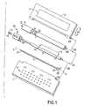
- the components of the hinge mechanism 30 of this invention are shown in disassembled relation in figure 1.
- the hinge assembly 30 is enlarged with respect to the panels.
- Panels 1 and 2 are connected by the hinge mechanism through aligned bores 22 and 23 to allow movement of the cover panel 2 relative to the base panel 1 in the direction of arrow 21 about the axis x-x.
- the cover panel 2 is allowed to move between a closed position at which it covers keyboard 3 and an open position at which the display 4 is visible and keyboard 4 is easily accessed.
- the total relative movement between the panels 1 and 2 is through an obtuse angle of about 135°.
- torsion bar 5 which is fixed at end 24 to the base panel 1 and at its other end 25 to cover panel 2 through damping barrel 6, cover support barrel 7, and cover coupling barrel 8, as described below.
- the torsion bar 5 will act as a spring which is charged by the closing movement of the cover panel 2 and releases when actuated by the user.
- End 25 of the torsion bar 5 is free to rotate (within a 135° range, while end 24 is fixed. This forces the bar 5 to twist during the closing motion of cover 2.
- Torsion bar 5 is constructed of an appropriate material that has a torsional elasticity which will return the bar 5 to its untwisted position.
- torsion bar 5 is constructed of superelastic nickel/titanium alloy wire, such as is sold under the trademark NITINOL by Nitinol Devices & Components of Fremont, CA.
- the superelasticity of this material combines to provide a spring of extremely compact form which has sufficient spring torque to open the display panel 2 and a suitable durability.
- a torsion bar having a diameter of .84mm and a length of 50mm has been used with good results.
- the torsion bar 5 forms the axially aligned base of the hinge assembly 30.
- the other parts of hinge 30 are cylindrical barrels which are assembled concentrically around the torsion bar 5.
- base 1 is mounted on torsion bar 5 through damping barrel 6 and is fixed to end 24 of torsion bar 5 through a base coupling barrel 9.
- Base coupling barrel 9 contains the release mechanism 31.
- Assembly reference bracket 27 is used to indicate that a cover support barrel 7 is also mounted on torsion bar 5, but over damping barrel 6.
- Cover support barrel 7 is fixed to end 25 of the torsion bar 5 and supports the cover panel 2.
- a cover coupling barrel 8 is fixed to one end of the cover support barrel 7 and engages the release mechanism 31 to hold the cover in the closed position.
- Damping barrel 6 is constructed with a pair of O-rings 11 and 12 mounted on its periphery. O-rings 11 and 12 form a damping chamber 10 in cooperation with the interior surface of bore 29 of cover support barrel 7. An appropriate grease can be confined within the chamber 10 to function as a viscous damping fluid. The friction between the cover support barrel 7 and damping barrel 6 during relative rotation of these members, creates a damping torque which controls the movement of the panel 2 under the influence of torsion bar 5.
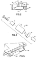
- the release mechanism 31 of the hinge assembly consists of a ball detent 16 mounted on a peripheral surface of base coupling barrel 9.
- Ball detent 16 is biased in the protruding position, as shown in figure 2, by a wedge shaped member 13.
- a spring 17 is positioned to exert a force on the wedge 13 in the direction shown by arrow 19.
- An actuating mechanism is connected through flange 14 of wedge member 13 to exert a release force in the direction shown by arrow 18 against spring 17.
- the actuation is accomplished by a button mounted on the axis of the hinge 31 and causing a force 18 to be exerted through an appropriate linkage.
- a shape memory wire is used, (also available from NDC of Fremont, CA) to actuate the spring detent release mechanism 31.
- a memory_wire 34 is connected to flange 14 as shown by a phantom line, in figure 2.
- the memory shape wire will contract under the influence of heat and move the wedge 13 against spring 17.
- Heat is provided by connecting the memory wire to a source of current such as a battery (not shown).
- the release mechanism of this embodiment will be actuated by pressing a button (not shown) to energize the memory wire. This allows the release button to be positioned in a more convenient position.
- Cover coupling barrel 8 is constructed with a cylindrical opening 15 which will engage ball detent 16 to lock the cover 2 is in the closed position.
- Cover coupling barrel 8 is mounted on cover support barrel 7 and may be allowed to rotate through a sector of 45° relative to barrel 7. This allows movement of the cover relative to the base to allow adjustment of the position of the cover beyond the 135° angle otherwise provided. This extra movement is needed to accommodate accidentally forced extension or more customized positioning of the display.
- the torsion bar 5 is not totally released at the 135° angle. A residual spring torque is maintained amounting to approximately a 30° rotation. Closing the cover recharges the spring torque to its opening energy.
- a pair of O-rings 32 and 33 may be mounted on the outer surface of barrel 7 to provide a friction damping torque for the relative motion of coupling barrel 8 on cover support barrel 7.
- torsion spring 5 In operation of the hinge of figure 1, the torsion spring 5 is twisted by the closing motion of cover 2. This generates a torque which is restrained by release mechanism 31, as ball detent 16 of base coupling barrel 9 engages opening 15 of cover coupling barrel 8. By retracting wedge element 13 from engagement with ball detent 16, the stored torque of torsion bar is released. Since cover support barrel 7 is free to rotate on damping barrel 6 and is fixed to the free end 25 of torsion bar 5, cover 2 will automatically open under the influence of viscous damping provided by the damping chamber 10.
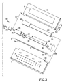
- FIG. 3 An alternate embodiment of the invention is shown in figures 3 and 4.
- a hinge assembly 50 is shown which is simplified by removing the release mechanism from the hinge assembly.
- the components of the hinge mechanism are shown in disassembled relation in figure 3.
- the hinge assembly 50 is enlarged with respect to the panels.
- Panels 1 and 2 are connected by the hinge mechanism 50 through aligned bores 52 and 53 to allow movement of the cover panel 2 relative to the base panel 1 in the direction of arrow 51 about the axis x-x.
- the cover panel 2 is allowed to move between a closed position at which it covers keyboard 3 and an open position at which the display 4 is visible and keyboard 4 is easily accessed.
- the total relative movement between the panels 1 and 2 is through an obtuse angle of about 135°.
- torsion bar 5 which is fixed at end 54 to cover panel 2 through damping barrel 6, and friction coupling barrel 59, as described below.
- End 55 of torsion bar 5 is connected to the base 1 through end 71 of support barrel 57.
- Opposite end 58 of support barrel 57 is fixed to base 1.
- the torsion bar 5 will act as a spring which is charged by the closing movement of the cover panel 2 and releases when actuated by the user.
- End 54 of the torsion bar 5 is free to rotate, while end 55 is relatively fixed. This forces the bar 5 to twist during the closing motion of cover 2.
- Torsion bar 5 is constructed of an appropriate superelastic material as described above.
- the torsion bar 5 forms the axially aligned base of the hinge assembly 50.
- the other parts of hinge 50 are cylindrical barrels which are assembled concentrically around the torsion bar 5.
- base 1 supports torsion bar 5 through support barrel 57 and is fixed to end 55 of torsion bar 5.
- Assembly reference bracket 67 is used to indicate that damping barrel 56 is also mounted on torsion bar 5, through internal bore 72 of support barrel 57.
- damping barrel 56 is connected through friction coupling barrel 59 to the cover 2.
- Key 78 engages the damping barrel 56 to allow limited relative rotation between the damping barrel 56 and torsion bar 5 in the amount of 135°, as shown by arrow 35.
- damping barrel 56 is constructed with a pair of O-rings 61 and 62 mounted on its periphery. O-rings 61 and 62 form a damping chamber 60 in cooperation with the interior surface of bore 72 of support barrel 57. An appropriate grease can be confined within the chamber 60 to function as a viscous damping fluid. The friction between the support barrel 57 and damping barrel 56 during relative rotation of these members, creates a damping force which controls the movement of the panel 2 under the influence of torsion bar 5.
- friction coupling barrel 59 is mounted for limited rotation on damping barrel 56.
- Coupling 59 is constructed of a series of cylindrical elements which include friction ring 74, body 75, and coupling ring 76.
- Body 75 is mounted on end 77 of damping barrel 56 through friction ring 74.
- Coupling ring 76 engages body 75 to allow limited rotation between damping barrel 56 and coupling barrel 59 in the amount of approximately 45°. This provides a safety measure for accidental extension of the cover or for customized adjustment.
- the friction between coupling barrel 59 and damping barrel 56 may be adjusted by the operation of screw 73 which engages a threaded hole in split end 77 of damping barrel 56. By rotation of the screw the split end 77 may be selectively enlarged or reduced to provide more or less coupling friction as desired, through engagement with friction ring 74.
- Torsion spring 5 is twisted by the closing motion of cover 2. This generates a torque which is restrained by an appropriate release mechanism which, when actuated releases the stored energy of the torsion bar and opens the cover. Since damping support barrel 56 is free to rotate up to 135° on torsion bar 5, cover 2 will open under the influence of viscous damping provided by the damping chamber 60.
- a hook or clasp type mechanism can be employed to hold the cover 2 in the restrained, closed position, while allowing release through one handed operation.
- Figure 5 shows a mechanism 80 for connecting the display 2 to the main printed circuit board of the device.
- the configuration of the hinge assemblies of this invention because of the small diameter hinge, facilitate the use of a flexible coiled plastic member 81 in which is imbedded wires (not shown) connected to display 2.
- the connection flap 82 contains the terminal ends of the wires which are inserted in base 2 for connection to the main printed circuit board.
- the mechanism 80 is coiled internally within the bore of the electronic device which also accommodates hinge mechanisms 30 or 50.
Abstract
Description
- Mobile telephones and similar communication devices are rapidly expanding in use and function. Such devices will soon provide Internet access, personal information management, facsimile, and messaging, in addition to telephone communication. This will require a user interface which is more complex, crowded and generally more difficult to use. In addition, electronic devices, such as mobile phones, pagers and the like, are being used in ever expanding situations and environments. With the complexity of use, a cover is generally used to protect against inadvertent actuation of the user interface and to provide additional functionality such as a display. The user interface, i.e. keyboard and display, remain covered when not in use. The cover therefore must be opened in order to allow use of the device. Covered keyboards and displays often require awkward manual maneuvers using two hands, to properly complete the opening of the device and adjust the relative position of the components. A mechanism is needed to easily open such covers with one hand. The movement of the cover must be well defined and accurate without allowing partial opening which defeats the single handed purpose. In the same instance, the motion cannot be unnecessarily jarring to the holder. In situations where the cover contains the display a considerable weight of about 50 grams may be involved and this requires a robust hinge mechanism.
- It is a purpose of this invention to provide a simple and efficient mechanism for opening an electronic device. It is also a purpose of this invention to make a hinge opening mechanism that is compact and that allows electrical contact through the hinge. It is a purpose of this invention to provide an opening motion which will be damped to allow an accurate and automatic opening of the device to a predetermined position, ready for use. It is a purpose of this invention to provide a robust hinge while minimizing diameter.
- The mechanism of this invention involves a hinge structure for connecting two generally flat panels for relative rotation about an axis. The panels form part of a handheld electronic device, for example, a mobile phone, pager, personal information manager or the like. These devices typically have a user interface which includes a keyboard and a display panel. The two panels must be movable between two positions, one at which the user interface is enclosed, inoperable and protected and another at which the components of the user interface are opened to operational position. The movement of the two panels is automatic and controlled to allow actuation using one hand.
- The hinge is constructed in an assembly of barrel shaped cylindrical components appropriately connected to each of the panels to provide the required motion. A torsion bar spring provides the energy for opening the panels and is biased in the open position. The spring is energized by the closing motion of the panels and released to provide the opening torque. The torsion bar spring is an elongated wire shaped member mounted at the axis of the hinge. A series of cylindrical barrels are mounted concentric with the torsion spring and form a connection across the hinge from one panel to the other.
- The torsion bar spring is fixed at one of its ends to the base panel and at its other end to the cover. The spring is chosen and mounted to provide a torque to the cover and is therefore free to rotate at the end to which the cover is fixed. The connection to the base panel is provided through a base coupling barrel which is constructed with a spring release mechanism actuatable by the user to release the spring torque and cause the cover to swing to its open position. A damper barrel is mounted concentrically over the torsion spring and is fixed to the base coupling barrel. A cover support barrel is in turn mounted concentrically over the damping barrel and is free to rotate on the damping barrel, but is fixed to the rotating end of the torsion spring. A pair of O-rings are mounted on the circumference of the damping barrel to form a chamber with the interior bore of the cover support barrel. This chamber may be filled with a viscous fluid to provide a damping friction for the movement of the cover support barrel. The cover support barrel has a cover coupling barrel which provides releasable engagement with the base coupling barrel.
- In an alternate embodiment, the release mechanism is removed to simplify the hinge assembly. In addition the connection to the cover is made through a friction coupling which permits additional rotation of the cover. The base is connected to the torsion spring through a support barrel within which a damping chamber is formed.
- The invention is described in more detail below with reference to the attached drawing in which:
- Figure 1 is an exploded view of the hinge of this invention;
- Figure 2 is a sectional view of the release mechanism of this invention;
- Figure 3 is an exploded view of a alternate embodiment of this invention;
- Figure 4 is an exploded perspective view of a friction coupling used in the alternate embodiment of figure 3; and
- Figure 5 is a perspective view of the electrical connector between the base and the display.
-
- The
panel opening hinge 30 of this invention is described below with reference to a personal information manager having abase panel 1 in which is mounted akeyboard 3 and acover panel 2 in which is mounted adisplay 4, but it should be noted that the system is equally adaptable to other types of electronic devices such as, computers, pagers, game controllers and the like. - The components of the
hinge mechanism 30 of this invention are shown in disassembled relation in figure 1. For convenience of illustration thehinge assembly 30 is enlarged with respect to the panels.Panels aligned bores cover panel 2 relative to thebase panel 1 in the direction ofarrow 21 about the axis x-x. Thecover panel 2 is allowed to move between a closed position at which it coverskeyboard 3 and an open position at which thedisplay 4 is visible andkeyboard 4 is easily accessed. The total relative movement between thepanels - The movement of the
cover 2 is provided throughtorsion bar 5 which is fixed atend 24 to thebase panel 1 and at itsother end 25 to coverpanel 2 through dampingbarrel 6, cover support barrel 7, andcover coupling barrel 8, as described below. Thetorsion bar 5 will act as a spring which is charged by the closing movement of thecover panel 2 and releases when actuated by the user.End 25 of thetorsion bar 5 is free to rotate (within a 135° range, whileend 24 is fixed. This forces thebar 5 to twist during the closing motion ofcover 2.Torsion bar 5 is constructed of an appropriate material that has a torsional elasticity which will return thebar 5 to its untwisted position. In the preferredembodiment torsion bar 5 is constructed of superelastic nickel/titanium alloy wire, such as is sold under the trademark NITINOL by Nitinol Devices & Components of Fremont, CA. The superelasticity of this material combines to provide a spring of extremely compact form which has sufficient spring torque to open thedisplay panel 2 and a suitable durability. A torsion bar having a diameter of .84mm and a length of 50mm has been used with good results. - The
torsion bar 5 forms the axially aligned base of thehinge assembly 30. The other parts ofhinge 30 are cylindrical barrels which are assembled concentrically around thetorsion bar 5. As shown byassembly bracket 26,base 1 is mounted ontorsion bar 5 through dampingbarrel 6 and is fixed toend 24 oftorsion bar 5 through a base coupling barrel 9. Base coupling barrel 9 contains therelease mechanism 31.Assembly reference bracket 27 is used to indicate that a cover support barrel 7 is also mounted ontorsion bar 5, but over dampingbarrel 6. Cover support barrel 7 is fixed to end 25 of thetorsion bar 5 and supports thecover panel 2. Acover coupling barrel 8 is fixed to one end of the cover support barrel 7 and engages therelease mechanism 31 to hold the cover in the closed position. - Damping
barrel 6 is constructed with a pair of O-rings rings chamber 10 in cooperation with the interior surface ofbore 29 of cover support barrel 7. An appropriate grease can be confined within thechamber 10 to function as a viscous damping fluid. The friction between the cover support barrel 7 and dampingbarrel 6 during relative rotation of these members, creates a damping torque which controls the movement of thepanel 2 under the influence oftorsion bar 5. - In one embodiment of the invention, as shown in figure 2, the
release mechanism 31 of the hinge assembly consists of aball detent 16 mounted on a peripheral surface of base coupling barrel 9.Ball detent 16 is biased in the protruding position, as shown in figure 2, by a wedge shapedmember 13. Aspring 17 is positioned to exert a force on thewedge 13 in the direction shown byarrow 19. An actuating mechanism is connected throughflange 14 ofwedge member 13 to exert a release force in the direction shown byarrow 18 againstspring 17. Preferably the actuation is accomplished by a button mounted on the axis of thehinge 31 and causing aforce 18 to be exerted through an appropriate linkage. In a preferred embodiment, a shape memory wire is used, (also available from NDC of Fremont, CA) to actuate the springdetent release mechanism 31. To accomplish this amemory_wire 34 is connected to flange 14 as shown by a phantom line, in figure 2. The memory shape wire will contract under the influence of heat and move thewedge 13 againstspring 17. Heat is provided by connecting the memory wire to a source of current such as a battery (not shown). The release mechanism of this embodiment will be actuated by pressing a button (not shown) to energize the memory wire. This allows the release button to be positioned in a more convenient position. -
Cover coupling barrel 8 is constructed with acylindrical opening 15 which will engageball detent 16 to lock thecover 2 is in the closed position.Cover coupling barrel 8 is mounted on cover support barrel 7 and may be allowed to rotate through a sector of 45° relative to barrel 7. This allows movement of the cover relative to the base to allow adjustment of the position of the cover beyond the 135° angle otherwise provided. This extra movement is needed to accommodate accidentally forced extension or more customized positioning of the display. To hold the cover in place, thetorsion bar 5 is not totally released at the 135° angle. A residual spring torque is maintained amounting to approximately a 30° rotation. Closing the cover recharges the spring torque to its opening energy. - A pair of O-
rings coupling barrel 8 on cover support barrel 7. - In operation of the hinge of figure 1, the
torsion spring 5 is twisted by the closing motion ofcover 2. This generates a torque which is restrained byrelease mechanism 31, asball detent 16 of base coupling barrel 9 engages opening 15 ofcover coupling barrel 8. By retractingwedge element 13 from engagement withball detent 16, the stored torque of torsion bar is released. Since cover support barrel 7 is free to rotate on dampingbarrel 6 and is fixed to thefree end 25 oftorsion bar 5,cover 2 will automatically open under the influence of viscous damping provided by the dampingchamber 10. - An alternate embodiment of the invention is shown in figures 3 and 4. In this embodiment a
hinge assembly 50 is shown which is simplified by removing the release mechanism from the hinge assembly. - The components of the hinge mechanism are shown in disassembled relation in figure 3. For convenience of illustration the
hinge assembly 50 is enlarged with respect to the panels.Panels hinge mechanism 50 through alignedbores cover panel 2 relative to thebase panel 1 in the direction ofarrow 51 about the axis x-x. Thecover panel 2 is allowed to move between a closed position at which it coverskeyboard 3 and an open position at which thedisplay 4 is visible andkeyboard 4 is easily accessed. The total relative movement between thepanels - The movement of the
cover 2 is provided throughtorsion bar 5 which is fixed atend 54 to coverpanel 2 through dampingbarrel 6, andfriction coupling barrel 59, as described below.End 55 oftorsion bar 5 is connected to thebase 1 throughend 71 ofsupport barrel 57. Oppositeend 58 ofsupport barrel 57 is fixed tobase 1. Thetorsion bar 5 will act as a spring which is charged by the closing movement of thecover panel 2 and releases when actuated by the user.End 54 of thetorsion bar 5 is free to rotate, whileend 55 is relatively fixed. This forces thebar 5 to twist during the closing motion ofcover 2.Torsion bar 5 is constructed of an appropriate superelastic material as described above. - The
torsion bar 5 forms the axially aligned base of thehinge assembly 50. The other parts ofhinge 50 are cylindrical barrels which are assembled concentrically around thetorsion bar 5. As shown byassembly bracket 66,base 1 supportstorsion bar 5 throughsupport barrel 57 and is fixed to end 55 oftorsion bar 5.Assembly reference bracket 67 is used to indicate that dampingbarrel 56 is also mounted ontorsion bar 5, throughinternal bore 72 ofsupport barrel 57. As shown in figure 3, dampingbarrel 56 is connected throughfriction coupling barrel 59 to thecover 2. Key 78 engages the dampingbarrel 56 to allow limited relative rotation between the dampingbarrel 56 andtorsion bar 5 in the amount of 135°, as shown byarrow 35. - As in the embodiment of figure 1, damping
barrel 56 is constructed with a pair of O-rings rings chamber 60 in cooperation with the interior surface ofbore 72 ofsupport barrel 57. An appropriate grease can be confined within thechamber 60 to function as a viscous damping fluid. The friction between thesupport barrel 57 and dampingbarrel 56 during relative rotation of these members, creates a damping force which controls the movement of thepanel 2 under the influence oftorsion bar 5. - As shown in figure 4,
friction coupling barrel 59 is mounted for limited rotation on dampingbarrel 56.Coupling 59 is constructed of a series of cylindrical elements which includefriction ring 74,body 75, andcoupling ring 76.Body 75 is mounted onend 77 of dampingbarrel 56 throughfriction ring 74. Couplingring 76 engagesbody 75 to allow limited rotation between dampingbarrel 56 andcoupling barrel 59 in the amount of approximately 45°. This provides a safety measure for accidental extension of the cover or for customized adjustment. The friction betweencoupling barrel 59 and dampingbarrel 56 may be adjusted by the operation ofscrew 73 which engages a threaded hole insplit end 77 of dampingbarrel 56. By rotation of the screw thesplit end 77 may be selectively enlarged or reduced to provide more or less coupling friction as desired, through engagement withfriction ring 74. - The operation of the embodiment of figure 3 is similar to hinge
assembly 30 described above.Torsion spring 5 is twisted by the closing motion ofcover 2. This generates a torque which is restrained by an appropriate release mechanism which, when actuated releases the stored energy of the torsion bar and opens the cover. Since dampingsupport barrel 56 is free to rotate up to 135° ontorsion bar 5,cover 2 will open under the influence of viscous damping provided by the dampingchamber 60. - In the embodiment of figure 3, a hook or clasp type mechanism can be employed to hold the
cover 2 in the restrained, closed position, while allowing release through one handed operation. - Figure 5 shows a
mechanism 80 for connecting thedisplay 2 to the main printed circuit board of the device. The configuration of the hinge assemblies of this invention, because of the small diameter hinge, facilitate the use of a flexible coiledplastic member 81 in which is imbedded wires (not shown) connected todisplay 2. Theconnection flap 82 contains the terminal ends of the wires which are inserted inbase 2 for connection to the main printed circuit board. Themechanism 80 is coiled internally within the bore of the electronic device which also accommodateshinge mechanisms
Claims (20)
- A hinge assembly for mounting a pair of substantially flat panels of an electronic device and providing a torque for rotating the panels between open and closed positions about an axis comprising:an elongated torsion bar spring supported on the panels at said axis of rotation and having first and second ends, said first end being fixed to one of said pairs of panels and said second end connected to said other of said pair of panels, wherein rotation of said panels from the open position to the closed position generates a torsional load on said torsion bar spring;a first cylindrical barrel mounted concentrically on said torsion bar and connected to one of said pair of panels; anda second cylindrical barrel mounted concentrically on said first cylindrical barrel for rotation thereon and connected to support the other of said pair of panels.
- A hinge assembly for mounting a pair of substantially flat panels of an electronic device and providing a torque for rotating the panels between open and closed positions about an axis, as described in claim 1, further comprising a coupling releasably constraining said other of said pair of panels in the closed position against the torque of the loaded torsion bar spring.
- A hinge assembly for mounting a pair of substantially flat panels of an electronic device and providing a torque for rotating the panels between open and closed positions about an axis, as described in claim 2, further comprising an actuator for releasing said other of said pair of panels to allow rotation of said other of said pair of panels to its open position under the torque of the torsion bar spring.
- A hinge assembly for mounting a pair of substantially flat panels of an electronic device and providing a torque for rotating the panels between open and closed positions about an axis, as described in claim 1, wherein said rotation of said second barrel on said first barrel is subject to viscous damping.
- A hinge assembly for mounting a pair of substantially flat panels of an electronic device and providing a torque for rotating the panels between open and closed positions about an axis, as described in claim 4, wherein said first barrel is constructed having a pair of O-rings mounted on the outer periphery thereof and said second barrel is constructed having an axially aligned bore to receive said first barrel therein and form a damping chamber for containing a viscous fluid in cooperation with said O-rings.
- A hinge assembly for mounting a pair of substantially flat panels of an electronic device and providing a torque for rotating the panels between open and closed positions about an axis, as described in claim 1, wherein said torsion bar spring is constructed of a superelastic nickel/titanium alloy wire.
- A hinge assembly for mounting a pair of substantially flat panels of an electronic device and providing a torque for rotating the panels between open and closed positions about an axis, as described in claim 1, wherein the coupling comprises:a first coupling barrel fixed to said first cylindrical barrel, said first coupling barrel having a locking latch constructed thereon; anda second coupling barrel mounted on said second cylindrical barrel for rotary motion therewith, said second coupling barrel having means to engage said locking latch to maintain the pair of panels in their closed position, wherein an actuator operates to unlatch said first and second coupling barrels.
- A hinge assembly for mounting a pair of substantially flat panels of an electronic device and providing a torque for rotating the panels between open and closed positions about an axis, as described in claim 7, wherein the latch comprises a ball detent which is spring biased into an extended position and wherein said means of engaging comprises an opening for receiving said extended ball detent, and said actuator is a manual button which retracts said extended ball detent against its biasing spring to cause the ball detent to withdraw from its extended position.
- A hinge assembly for mounting a pair of substantially flat panels of an electronic device and providing a torque for rotating the panels between open and closed positions about an axis, as described in claim 7, wherein said actuator is operated by means of a shape memory wire, said memory wire being caused to contract when heated and unlatch said coupling barrels.
- A hinge assembly for mounting a pair of substantially flat panels of an electronic device and providing a torque for rotating the panels between open and closed positions about an axis, as described in claim 1, wherein an electrical connection is formed between said panels and connection comprises a coiled plastic sheet positioned within the hinge to allow rotation of the hinge components, said coiled plastic sheet having connecting wires impeded therein to form an electrical connection across said hinge.
- An electronic device having a display and base, said base containing a user interface, a control processor, and a source of power, said electronic device comprising:a first panel containing said display;a second panel containing said user interface, said control processor, and said source of power;a hinge assembly for connecting said first and second panels for relative rotation of one of said panels with respect to the other of said panels between open and closed positions about an axis, said hinge assembly further comprising:an elongated torsion bar spring supported on the panels at said axis of rotation and having first and second ends, said first end being fixed to one of said panels and said second end connected to said other of said panels, wherein rotation of said panels from the open position to the closed position generates a torsional load on said torsion bar spring;a first cylindrical barrel mounted concentrically on said torsion bar and connected to one of said panels; anda second cylindrical barrel mounted concentrically on said first cylindrical barrel for rotation thereon and connected to support the other of said panels.
- An electronic device having a display and base, said base containing a user interface, a control processor, and a source of power, said electronic device, as described in claim 11, further comprising a coupling releasably constraining said other of said pair of panels in the closed position against the torque of the loaded torsion bar spring.
- An electronic device having a display and base, said base containing a user interface, a control processor, and a source of power, said electronic device, as described in claim 12, further comprising an actuator for releasing said other of said panels to allow rotation of said other of said panels to its open position under the torque of the torsion bar spring.
- An electronic device having a display and base, said base containing a user interface, a control processor, and a source of power, said electronic device, as described in claim 11, wherein said rotation of said second barrel on said first barrel is subject to viscous damping.
- An electronic device having a display and base, said base containing a user interface, a control processor, and a source of power, said electronic device, as described in claim 14, wherein said first barrel is constructed having a pair of O-rings mounted on the outer periphery thereof and said second barrel is constructed having an axially aligned bore to receive said first barrel therein and form a damping chamber for containing a viscous fluid in cooperation with said O-rings.
- An electronic device having a display and base, said base containing a user interface, a control processor, and a source of power, said electronic device, as described in claim 11, wherein said torsion bar spring is constructed of a superelastic nickel/titanium alloy wire.
- An electronic device having a display and base, said base containing a user interface, a control processor, and a source of power, said electronic device, as described in claim 12, wherein the coupling comprises:a first coupling barrel fixed to said first cylindrical barrel, said first coupling barrel having a locking latch constructed thereon; anda second coupling barrel mounted on said second cylindrical barrel for rotary motion therewith, said second coupling barrel having means to engage said locking latch to maintain said panels in their closed position, wherein an actuator operates to unlatch said first and second coupling barrels.
- An electronic device having a display and base, said base containing a user interface, a control processor, and a source of power, said electronic device, as described in claim 17, wherein the latch comprises a ball detent which is spring biased into an extended position and wherein said means of engaging comprises an opening for receiving said extended ball detent, and said actuator is a manual button which retracts said extended ball detent against its biasing spring to cause the ball detent to withdraw from its extended position.
- A hinge assembly for mounting a pair of substantially flat panels of an electronic device and providing a torque for rotating said panels between open and closed positions about an axis, as described in claim 17, wherein said actuator is operated by means of a shaped memory wire, said memory wire being caused to contract when heated and unlatch said coupling barrels.
- An electronic device having a display and base, said base containing a user interface, a control processor, and a source of power, said electronic device, as described in claim 11, wherein an electrical connection is formed between said panels and connection comprises a coiled plastic sheet positioned within the hinge to allow rotation of the hinge components, said coiled plastic sheet having connecting wires impeded therein to form an electrical connection across said hinge.
Applications Claiming Priority (2)
| Application Number | Priority Date | Filing Date | Title |
|---|---|---|---|
| US09/733,146 US20020069483A1 (en) | 2000-12-08 | 2000-12-08 | Apparatus for opening hand held electronic device |
| US733146 | 2000-12-08 |
Publications (2)
| Publication Number | Publication Date |
|---|---|
| EP1213640A2 true EP1213640A2 (en) | 2002-06-12 |
| EP1213640A3 EP1213640A3 (en) | 2003-10-15 |
Family
ID=24946420
Family Applications (1)
| Application Number | Title | Priority Date | Filing Date |
|---|---|---|---|
| EP01309232A Withdrawn EP1213640A3 (en) | 2000-12-08 | 2001-10-31 | Apparatus for opening hand held electronic device |
Country Status (2)
| Country | Link |
|---|---|
| US (1) | US20020069483A1 (en) |
| EP (1) | EP1213640A3 (en) |
Families Citing this family (23)
| Publication number | Priority date | Publication date | Assignee | Title |
|---|---|---|---|---|
| TW487258U (en) * | 2001-02-15 | 2002-05-11 | Quanta Comp Inc | Pivot structure of a mobile phone detachable from a base thereof |
| US6746067B2 (en) * | 2001-09-04 | 2004-06-08 | Lear Corporation | Control panel for a vehicle |
| US20060046792A1 (en) * | 2004-08-31 | 2006-03-02 | Hassemer Brian J | Hinge apparatus and methods therefor |
| TWI413037B (en) * | 2007-06-15 | 2013-10-21 | Creator Technology Bv | Electronic device with a variable angulation of a flexible display |
| US8441791B2 (en) | 2010-12-23 | 2013-05-14 | Microsoft Corporation | Double hinge radial cams |
| US8451601B2 (en) | 2011-01-31 | 2013-05-28 | Microsoft Corporation | Double hinge axial cams |
| US9535465B2 (en) | 2011-02-10 | 2017-01-03 | Microsoft Technology Licensing, Llc | Hinge electrical interconnection guide |
| US8780570B2 (en) | 2011-02-14 | 2014-07-15 | Microsoft Corporation | Double hinge torsion bar |
| US8773849B2 (en) | 2011-04-11 | 2014-07-08 | Microsoft Corporation | Extendable connecting link |
| US8540062B2 (en) | 2011-05-20 | 2013-09-24 | Research In Motion Limited | Low profile rotary damper |
| US9348372B2 (en) * | 2014-06-13 | 2016-05-24 | Apple Inc. | Friction hinge with embedded counterbalance |
| US9725940B2 (en) | 2014-07-24 | 2017-08-08 | Michael Lambright | Door hinge closing mechanism |
| KR102242319B1 (en) * | 2014-08-22 | 2021-04-20 | 삼성전자주식회사 | Cover device and eletronic device having thereof |
| US10133360B2 (en) * | 2016-03-02 | 2018-11-20 | Dell Products L.P. | Information handling system low profile keyboard |
| FR3053748B1 (en) * | 2016-07-06 | 2018-07-13 | A Raymond Et Cie | REINFORCED TORSION BAR HING ASSEMBLY |
| US9910463B1 (en) | 2016-08-12 | 2018-03-06 | Microsoft Technology Licensing, Llc | Combination hardstop and switch for actuated locking devices |
| US9785196B1 (en) * | 2016-08-18 | 2017-10-10 | Microsoft Technology Licensing, Llc | Capture connector for actuated locking devices |
| TWI687794B (en) * | 2017-09-15 | 2020-03-11 | 仁寶電腦工業股份有限公司 | Dual axes hinge assembly and electronic device |
| US10579158B2 (en) | 2017-11-01 | 2020-03-03 | Dell Products L.P. | Information handling system predictive key retraction and extension actuation |
| US10579159B2 (en) | 2017-11-01 | 2020-03-03 | Dell Products L.P. | Information handling system integrated device actuator monitoring |
| US10222872B1 (en) * | 2017-11-01 | 2019-03-05 | Dell Products L.P. | Information handling system integrated device key actuator |
| US11353933B2 (en) | 2020-05-27 | 2022-06-07 | Apple Inc. | Self-actuating hinge mechanism for electronic device |
| NL2031418B1 (en) * | 2022-03-28 | 2023-10-13 | Microsoft Technology Licensing Llc | Rotating magnet assembly in a foldable device |
Citations (4)
| Publication number | Priority date | Publication date | Assignee | Title |
|---|---|---|---|---|
| JPS62175817A (en) * | 1986-01-29 | 1987-08-01 | Matsushita Electric Ind Co Ltd | Display device |
| US5636275A (en) * | 1995-03-31 | 1997-06-03 | Fujitsu Limited | Hinge mechanism and foldable portable telephone having the hinge mechanism |
| US5923751A (en) * | 1994-11-15 | 1999-07-13 | Katoh Electrical Machinery Co., Ltd. | Opening and closing device for a portable telephone |
| US6104621A (en) * | 1998-06-30 | 2000-08-15 | Ericsson, Inc. | Torsional hinging mechanism |
-
2000
- 2000-12-08 US US09/733,146 patent/US20020069483A1/en not_active Abandoned
-
2001
- 2001-10-31 EP EP01309232A patent/EP1213640A3/en not_active Withdrawn
Patent Citations (4)
| Publication number | Priority date | Publication date | Assignee | Title |
|---|---|---|---|---|
| JPS62175817A (en) * | 1986-01-29 | 1987-08-01 | Matsushita Electric Ind Co Ltd | Display device |
| US5923751A (en) * | 1994-11-15 | 1999-07-13 | Katoh Electrical Machinery Co., Ltd. | Opening and closing device for a portable telephone |
| US5636275A (en) * | 1995-03-31 | 1997-06-03 | Fujitsu Limited | Hinge mechanism and foldable portable telephone having the hinge mechanism |
| US6104621A (en) * | 1998-06-30 | 2000-08-15 | Ericsson, Inc. | Torsional hinging mechanism |
Non-Patent Citations (1)
| Title |
|---|
| PATENT ABSTRACTS OF JAPAN vol. 012, no. 023 (P-658), 23 January 1988 (1988-01-23) & JP 62 175817 A (MATSUSHITA ELECTRIC IND CO LTD), 1 August 1987 (1987-08-01) * |
Also Published As
| Publication number | Publication date |
|---|---|
| US20020069483A1 (en) | 2002-06-13 |
| EP1213640A3 (en) | 2003-10-15 |
Similar Documents
| Publication | Publication Date | Title |
|---|---|---|
| EP1213640A2 (en) | Apparatus for opening hand held electronic device | |
| US6148480A (en) | Hinge construction with a snap-open, snap-shut feel, for a folding mobile phone handset | |
| JP4845558B2 (en) | Portable device | |
| US9310848B2 (en) | Electronic apparatus with a torque variable structure connecting housing components | |
| EP0692899B1 (en) | Foldable portable wireless telephone apparatus | |
| KR100439066B1 (en) | Hinge structure for collapsible portable phone | |
| US7513010B2 (en) | Automatic opening hinge assembly for portable electronic device | |
| EP1507388B1 (en) | Foldable mobile phone with one touch opening function | |
| US7647674B2 (en) | Automatically opening hinge assembly for portable electronic devices | |
| US20070084015A1 (en) | Hinge assembly system for portable electronic devices | |
| EP1573159B1 (en) | A mobile terminal with a hinge, a method of operating the mobile terminal and a hinge | |
| US20060242796A1 (en) | Automatical opening hinge assembly for portable electronic devices | |
| JPWO2002077472A1 (en) | Hinge structure with rotary actuator | |
| EP0381202A1 (en) | Shaft lock device with coil spring inserted in rotational shaft of hinge mechanism and portable information processing apparatus with shaft lock device | |
| GB2437542A (en) | Mouse with a damped pivoting back door, side clasp buttons and a movable carrier for a wireless receiver | |
| US8056187B2 (en) | Hinge assembly | |
| US6817061B2 (en) | Hinge for foldable cellular phones | |
| US8233945B2 (en) | Rotary cover mechanism for portable electronic devices | |
| US6122801A (en) | Hinge mechanism | |
| US20060064849A1 (en) | Hinge and foldable electronic device using the hinge | |
| US20050005401A1 (en) | Hinge device for portable terminal having sub-housing stopper | |
| CN109253153B (en) | Automatic standing opening and closing device of terminal machine and terminal machine using same | |
| US20040203519A1 (en) | Transformer hinge design | |
| KR100810496B1 (en) | Hinge module for folder-typed portable terminal | |
| JPH0374372B2 (en) |
Legal Events
| Date | Code | Title | Description |
|---|---|---|---|
| PUAI | Public reference made under article 153(3) epc to a published international application that has entered the european phase |
Free format text: ORIGINAL CODE: 0009012 |
|
| AK | Designated contracting states |
Kind code of ref document: A2 Designated state(s): AT BE CH CY DE DK ES FI FR GB GR IE IT LI LU MC NL PT SE TR |
|
| AX | Request for extension of the european patent |
Free format text: AL;LT;LV;MK;RO;SI |
|
| PUAL | Search report despatched |
Free format text: ORIGINAL CODE: 0009013 |
|
| AK | Designated contracting states |
Kind code of ref document: A3 Designated state(s): AT BE CH CY DE DK ES FI FR GB GR IE IT LI LU MC NL PT SE TR |
|
| AX | Request for extension of the european patent |
Extension state: AL LT LV MK RO SI |
|
| AKX | Designation fees paid | ||
| REG | Reference to a national code |
Ref country code: DE Ref legal event code: 8566 |
|
| STAA | Information on the status of an ep patent application or granted ep patent |
Free format text: STATUS: THE APPLICATION IS DEEMED TO BE WITHDRAWN |
|
| 18D | Application deemed to be withdrawn |
Effective date: 20040504 |