EP1211571A2 - Developing roller having developing sleeve conveying developer without imposing stress by regulating member - Google Patents
Developing roller having developing sleeve conveying developer without imposing stress by regulating member Download PDFInfo
- Publication number
- EP1211571A2 EP1211571A2 EP01310062A EP01310062A EP1211571A2 EP 1211571 A2 EP1211571 A2 EP 1211571A2 EP 01310062 A EP01310062 A EP 01310062A EP 01310062 A EP01310062 A EP 01310062A EP 1211571 A2 EP1211571 A2 EP 1211571A2
- Authority
- EP
- European Patent Office
- Prior art keywords
- developer
- developing sleeve
- developing
- roller
- regulating member
- Prior art date
- Legal status (The legal status is an assumption and is not a legal conclusion. Google has not performed a legal analysis and makes no representation as to the accuracy of the status listed.)
- Granted
Links
Images


Classifications
-
- G—PHYSICS
- G03—PHOTOGRAPHY; CINEMATOGRAPHY; ANALOGOUS TECHNIQUES USING WAVES OTHER THAN OPTICAL WAVES; ELECTROGRAPHY; HOLOGRAPHY
- G03G—ELECTROGRAPHY; ELECTROPHOTOGRAPHY; MAGNETOGRAPHY
- G03G15/00—Apparatus for electrographic processes using a charge pattern
- G03G15/06—Apparatus for electrographic processes using a charge pattern for developing
- G03G15/08—Apparatus for electrographic processes using a charge pattern for developing using a solid developer, e.g. powder developer
- G03G15/09—Apparatus for electrographic processes using a charge pattern for developing using a solid developer, e.g. powder developer using magnetic brush
- G03G15/0921—Details concerning the magnetic brush roller structure, e.g. magnet configuration
- G03G15/0928—Details concerning the magnetic brush roller structure, e.g. magnet configuration relating to the shell, e.g. structure, composition
Definitions
- a developing roller in a developing device used in an image forming apparatus such as a copying machine, a facsimile, a printer, and so forth generally includes a developing sleeve and a magnet.
- a developer is carried on a surface of the developing sleeve and conveyed to develop a latent image formed on a surface of a photoconductive element into a visible image. If an amount of the developer on the surface of the developing sleeve is not uniform, the developed visible image has an uneven image density, resulting in a degradation of a produced image. Therefore, it is preferable that the amount of the developer on the surface of the developing sleeve is uniform.
- a regulating member which is referred to as a doctor, is generally employed.
- the developing roller includes a magnet roller including a plurality of magnets configured to attract the developer, and a developing sleeve provided outside of the magnet roller and configured to carry and convey the developer while bearing the developer by a magnetic force of the magnet roller.
- the surface of the developing sleeve is configured such that a transportation capacity of the developer in end portions of the developing sleeve which correspond to a vicinity of ends of the magnet roller is smaller than the transportation capacity of the developer in a central portion of the developing sleeve which corresponds to a central portion of the magnet roller.
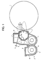
- FIG. 1 is a schematic drawing illustrating a construction of a developing device of an image forming apparatus according to the present invention.
- a photoconductive drum 1 as an image bearing member is rotatably driven by a driving device (not shown) when an image is formed.
- the photoconductive drum 1 is then uniformly charged by a charging device (not shown).
- a surface of the photoconductive drum 1 is exposed with a beam light emitted from an exposure device (e.g., a writing device) to form an electrostatic latent image thereon.
- an exposure device e.g., a writing device
- Fig. 3A is a diagram illustrating the magnetic force 9 of the magnet 3a in the normal direction disposed in a central portion of the magnet roller 3b.
- Fig. 3B is a diagram illustrating the magnetic force 9 of the magnet 3a in the normal direction disposed in ends of the magnet roller 3b.
- Fig. 3C is a diagram illustrating the magnetic force 9 of the magnet 3a in the normal direction disposed in the central portion of the magnet roller 3b, and the developer 11 on the developing sleeve 3c.
- Fig. 3D is a diagram illustrating the magnetic force 9 of the magnet 3a in the normal direction disposed in the ends of the magnet roller 3b, and the developer 11 on the developing sleeve 3c.
- An amount of a developer that passes the regulating member 10 is increased when the magnetic brush 11 passes the regulating member 10 while the magnetic brush 11 on the developing sleeve 3c is inclined toward the surface side of the developing sleeve 3c compared to a case where the magnetic brush 11 on the developing sleeve 3c passes the regulating member 10 in an upright posture.
- a friction between the developing sleeve 3c and developer 11 is increased as the degree of the surface roughness of the developing sleeve 3c is increased.
- a force in which the developer 11 passes the regulating member 10 is increased as illustrated in Fig. 7A.
- the passing force of the developer 11 passing the regulating member 10 is decreased if the degree of the surface roughness of the developing sleeve 3c is decreased because the friction between the developing sleeve 3c and developer 11 is decreased as illustrated in Fig. 7B.
- An arrow in Figs. 7A and 7B indicates a moving direction of the developer 11.
- An amount of the developer 11 on the surface of the developing sleeve 3c corresponding to the vicinity of ends of the magnet roller 3b is decreased without imposing a stress on the developer 11 if a degree of a surface roughness of end portions of the developing sleeve 3c, which correspond to ends of the magnet roller 3b, is decreased compared to the degree of the surface roughness of the central portion thereof, which corresponds to a central portion of the magnet roller 3b, thereby preventing an occurrence of the above-described phenomenon.
Abstract
Description
- The present invention relates to a developing roller in a developing device to be used in an image forming apparatus, such as a copying machine, a facsimile, a printer, and so forth, and more particularly to a developing sleeve wherein an amount of a developer on a surface of the developing sleeve is made uniform without imposing a stress on the developer by a regulating member.
- A developing roller in a developing device used in an image forming apparatus, such as a copying machine, a facsimile, a printer, and so forth generally includes a developing sleeve and a magnet. A developer is carried on a surface of the developing sleeve and conveyed to develop a latent image formed on a surface of a photoconductive element into a visible image. If an amount of the developer on the surface of the developing sleeve is not uniform, the developed visible image has an uneven image density, resulting in a degradation of a produced image. Therefore, it is preferable that the amount of the developer on the surface of the developing sleeve is uniform. In order to keep the amount of the developer on the surface of the developing sleeve uniform, a regulating member, which is referred to as a doctor, is generally employed.
- The amount of the developer in end portions of the developing sleeve is increased compared to that of the developer in a central portion of the developing sleeve because of a wraparound magnetic force generated by an end portion of a magnet. Thus, the amount of the developer is locally increased in the vicinity of the end portion of the magnet, resulting in a coagulation of the developer on the surface of the developing sleeve due to a stress imposed on the developer.
- In Japanese Patent Laid-Open Publication No. 9-265238, a technology for reducing an amount of a developer in the vicinity of a magnet by changing a magnetic force exerted on the doctor or a shape of the doctor to increase a regulating force of the doctor. In the above-described technology, the developer that passes the doctor undergoes a stress. Thus, a strain is given on the developer. The developer that undergoes the stress tends to move to a portion of the developing sleeve where a reduced stress is imposed on the developer.
- If the strain is given on the developer, a property of the developer may change, resulting in an early deterioration of the developer. In addition, when the developer moves to the portion of the developing sleeve where a reduced stress is imposed on the developer, an amount of the developer increases locally at this portion of the developing sleeve, resulting in the coagulation of the developer. In addition, a developer scatters when the developer undergoes a stress imposed by the regulating member.
- The present invention has been made in view of the above-mentioned and other problems and addresses the above-discussed and other problems.
- The present invention advantageously provides a novel developing roller, developing device using the developing roller ,and image forming apparatus using the developing device, wherein a developer on a developing sleeve is uniformed without imposing a stress on the developer by a regulating member, thereby an coagulation of the developer on the developing sleeve is prevented. In addition, a scatter of the developer, an early deterioration of the developer, and a deterioration of a sealing member by the developing sleeve are prevented.
- According to an example of the present invention, the developing roller includes a magnet roller including a plurality of magnets configured to attract the developer, and a developing sleeve provided outside of the magnet roller and configured to carry and convey the developer while bearing the developer by a magnetic force of the magnet roller. The surface of the developing sleeve is configured such that a transportation capacity of the developer in end portions of the developing sleeve which correspond to a vicinity of ends of the magnet roller is smaller than the transportation capacity of the developer in a central portion of the developing sleeve which corresponds to a central portion of the magnet roller.
- A more complete appreciation of the present invention and many of the attendant advantages thereof will be readily obtained as the same becomes better understood by reference to the following detailed description when considered in connection with the accompanying drawings, wherein:
- Fig. 1 is a schematic drawing illustrating a construction of a developing device of an image forming apparatus according to a first example of the present invention;
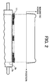
- Fig. 2 is a diagram illustrating a magnetic force and an amount of a developer on a developing sleeve;
- Figs. 3A and 3B are diagrams illustrating the magnetic force in a normal direction;
- Figs . 3C and 3D are diagrams illustrating the magnetic force in the normal direction and the developer on the developing sleeve;
- Figs. 4A, 4B, 4C, and 4D are diagrams illustrating a developing sleeve and a regulating member in a background art;
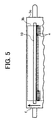
- Fig. 5 is a diagram illustrating a force exerted on the regulating member and a movement of the developer;
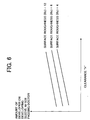
- Fig. 6 is a diagram illustrating a relationship among an
amount of a clearance between the regulating
member 10 and the developingsleeve 3c, a degree of a surface roughness of the developingsleeve 3c, and an amount of thedeveloper 11 adheres to the developingsleeve 3c; - Figs. 7A and 7B are diagrams illustrating a force in which the developer passes the regulating member; and
- Fig. 8 is a diagram illustrating a surface roughness of the developing sleeve according to the first and a second example of the present invention.
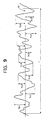
- Figure 9 is a diagram illustrating the method of obtaining ten-point mean roughness Rz.
-
- Referring now to the drawings, wherein like reference numerals designate identical or corresponding parts throughout the several views, Fig. 1 is a schematic drawing illustrating a construction of a developing device of an image forming apparatus according to the present invention. In an image forming apparatus in which the developing device is used, a
photoconductive drum 1 as an image bearing member is rotatably driven by a driving device (not shown) when an image is formed. Thephotoconductive drum 1 is then uniformly charged by a charging device (not shown). Thus, a surface of thephotoconductive drum 1 is exposed with a beam light emitted from an exposure device (e.g., a writing device) to form an electrostatic latent image thereon. A developingdevice 2 develops the electrostatic latent image formed on the surface of thephotoconductive drum 1 into a visible image with toner (i.e. , a toner image) . The toner image is transferred onto a transfer sheet, which is fed by a feeding device (not shown), by a transfer device (not shown). - The toner image transferred onto the transfer sheet is fixed by a fixing device (not shown). The transfer sheet is then discharged to outside the apparatus. The
photoconductive drum 1 is cleaned by a cleaning device (not shown) after the toner image has been transferred onto the transfer sheet. The above-described image forming operation is continuously repeated until the set number of prints is completed. A belt-type photoconductive element may be employed instead of thephotoconductive drum 1. - In the developing
device 2, a developing roller 3 (i.e., a developer bearing member) is provided in adeveloper container 6 at a position opposed to thephotoconductive element 1 through an inlet of thedeveloper container 6. Thedeveloper container 6 includes anupper case 3 and alower case 4. End portions of the developingrollers 3 are rotatably supported by end portions of the developer container 6.Conveying screws 7 and 8 (i.e., an agitation device) are provided in thedeveloper container 6. End portions of conveyingscrews 7 and 8 are rotatably supported by end portions of thedeveloper container 6. Conveyingscrews 7 and 8 are rotatably driven by a driving source (not shown) . Conveyingscrews 7 and 8 circulate a developer (e.g., a two-component developer including toner and a magnetic carrier) in thedeveloper container 6 while agitating the developer and conveying it to the developingroller 3. - The developing
roller 3 includes amagnet roller 3b and a developingsleeve 3c. Themagnet roller 3b includes a plurality ofmagnets 3a inside. The developingsleeve 3c is provided outside of themagnet roller 3b to carry and convey a developer. Themagnet roller 3b is fixedly provided. The developingsleeve 3c is rotatably driven by a driving source (not shown) in a direction indicated by an arrow in Fig. 1. The developer adheres to a surface of the developer sleeve 3c by amagnetic force 9 of the plurality ofmagnets 3a to form a magnetic brush. The magnetic brush is supplied to a developing region formed between thephotoconductive drum 1 and the developingsleeve 3c. - The developer unevenly adheres to the surface of the developing
sleeve 3c. Thus, a regulating member 10 (which is referred to as a doctor) is provided to a position above the circumferential surface of the developingsleeve 3c while creating a clearance "h" of a predetermined amount between the circumferential surface of the developingsleeve 3c and the regulatingmember 10. The regulatingmember 10 regulates an amount of the developer on the surface of thedeveloper sleeve 3c so that an even amount of the developer is supplied to the developing region. Although the non-magnetic regulating member is employed to simplify a construction of the developingdevice 2, a magnetic regulating member or a regulating member including a non-magnetic regulating member and a magnetic board may be employed. - Even though the amount of the clearance "h" between the developing
sleeve 3c and theregulation member 10 is uniformly created in a longitudinal direction, an amount of a developer 11 (i.e., magnetic brush) on the surface of the developingsleeve 3c is increased in the order of a location of thedeveloper 11, namely, in the order of thedeveloper 11 located close to ends themagnet roller 3b such that the amount of thedeveloper 11 is largest in regions adjacent to the ends of themagnet roller 3b as illustrated in Fig. 2. - The above-described phenomenon occurs in relation to a line of magnetic force of the
magnet 3a. For example, as illustrated in Fig. 2, the magnetic force is large at an edge of themagnet 3a when the magnetic force of themagnet 3a, positioned at immediate upstream side of the regulatingmember 10, in a direction of normal is observed. A relationship between the magnetic force and the amount of the developer on the surface of the developingsleeve 3c is described below. The relationship is identical to each magnet of the plurality ofmagnets 3a. Thus, the description is made based on the relationship between the magnetic force of one magnet and the amount of the developer on the surface of the developingsleeve 3c. - Fig. 3A is a diagram illustrating the
magnetic force 9 of themagnet 3a in the normal direction disposed in a central portion of themagnet roller 3b. Fig. 3B is a diagram illustrating themagnetic force 9 of themagnet 3a in the normal direction disposed in ends of themagnet roller 3b. Fig. 3C is a diagram illustrating themagnetic force 9 of themagnet 3a in the normal direction disposed in the central portion of themagnet roller 3b, and thedeveloper 11 on the developingsleeve 3c. Fig. 3D is a diagram illustrating themagnetic force 9 of themagnet 3a in the normal direction disposed in the ends of themagnet roller 3b, and thedeveloper 11 on the developingsleeve 3c. As described above, themagnetic force 9 of themagnet 3a in the normal direction disposed in ends of themagnet roller 3b differs from that of themagnet 3a in the normal direction disposed in the central portion of themagnet roller 3b. The larger themagnetic force 9 in the normal direction, the larger themagnetic force 9 in a tangent line direction. Themagnetic force 9 in the tangent line direction produces an effect of inclining themagnetic brush 11 toward a surface side of the developingsleeve 3c. An amount of a developer that passes the regulatingmember 10 is increased when themagnetic brush 11 passes the regulatingmember 10 while themagnetic brush 11 on the developingsleeve 3c is inclined toward the surface side of the developingsleeve 3c compared to a case where themagnetic brush 11 on the developingsleeve 3c passes the regulatingmember 10 in an upright posture. - As described above, the
magnetic force 9 in the normal direction at ends of themagnet roller 3b is larger than that in the central portion thereof due to an effect of a wraparound magnetic force. Thus, themagnetic force 9 in the tangent line direction at ends of themagnet roller 3b becomes larger than that in the central portion thereof. Because themagnetic force 9 in the tangent line direction has the effect of inclining themagnetic brush 11 toward the surface side of the developingsleeve 3c, an increased amount of a developer passes the regulatingmember 10 at ends of themagnet roller 3b compared to the amount of the developer that passes the regulatingmember 10 in the central portion of themagnet roller 3b, even if the clearance "h" between the developingsleeve 3c and the regulatingmember 10 is uniformly created in the direction of the length. Due to the above-described mechanism, the amount of the developer in end portions of the surface of the developingsleeve 3c is larger than that in the central portion thereof. - To prevent the above-described inconvenience, several attempts have been made to have the same amount of a developer in both end and central portions of the
magnet roller 3b. For example, As illustrated in Figs. 4A and 4B, an amount of a clearance "h2" at ends of themagnet roller 3b is decreased without changing an amount of a clearance "h1" in the central portion of themagnet roller 3b. As illustrated in Figs. 4C and 4D,when amagnetic regulating member 10a is employed, a thickness of the magnetic regulatingmember 10a is made larger in an end portions of the magnetic regulatingmember 10a (i.e., "t2") without changing the thickness of the magnetic regulatingmember 10a in a central portion thereof (i.e., "t1"). - However, in this case, a developer in end portions of the developing
sleeve 3c undergoes an increased stress in the vicinity of the regulating member compared to the stress of the developer in the central portion of the developingsleeve 3c. Thus, a strain is given on the developer, resulting in an early deterioration of the developer. As illustrated in Fig. 5, because the developer at ends of themagnet roller 3b where the developer undergoes the increased stress moves to the central portion of themagnet roller 3b where the developer undergoes the reduced stress, an amount of the developer locally increases in the vicinity of a boundary between the portion of the regulating member where the regulating force is increased and the portion thereof where the regulating force is not increased. Hence, the developer is coagulated in the vicinity of the boundary. In Fig. 5, an arrow "e" indicates a force exerted on the regulatingmember 10 and a movement of the developer. An arrow "f" indicates a rotating direction of the developingsleeve 3c. - A first example of the present invention, in which an amount of a developer in the vicinity of ends of the
magnet roller 3b is decreased without imposing a stress on the developer, is described below. Fig. 6 is a diagram illustrating a relationship among an amount of the clearance "h" between the regulatingmember 10 and the developingsleeve 3c, a degree of a surface roughness of the developingsleeve 3c, and an amount of thedeveloper 11 adheres to the developingsleeve 3c. - Surface roughness can be measured according to a ten-point mean roughness (Rz) determined by JIS B0601 (Japanese Industrial Standards). The definition of Rz is the arithmetic mean of values of ten-point mean roughness measured at various parts chosen at random on a surface of an object. A method of obtaining ten-point mean roughness Rz is illustrated in Fig. 9. A portion having a
measurement length 1 is sampled from a waviness curve. The heights of the five highest peaks from the center line m (i.e., Yp1, Yp2, Yp3, Yp4 and Yp5) are measured. In addition, the depths of the five deepest valleys from the center line m (i.e., Yv1, Yv2, Yv3, Yv4 and Yv5) are measured. The ten-point mean roughness Rz of the surface is determined by the following equation: - As can be seen in Fig. 6, the amount of the
developer 11 increases as the surface of the developingsleeve 3c is made rougher if the amount of the clearance "h" is the same. The amount of thedeveloper 11 increases as the amount of the clearance "h" is increased if the degree of the surface roughness of the developingsleeve 3c is the same. - A friction between the developing
sleeve 3c anddeveloper 11 is increased as the degree of the surface roughness of the developingsleeve 3c is increased. Thus, when regulating the amount of thedeveloper 11 by the regulatingmember 10, a force in which thedeveloper 11 passes the regulatingmember 10 is increased as illustrated in Fig. 7A. To the contrary, the passing force of thedeveloper 11 passing the regulatingmember 10 is decreased if the degree of the surface roughness of the developingsleeve 3c is decreased because the friction between the developingsleeve 3c anddeveloper 11 is decreased as illustrated in Fig. 7B. An arrow in Figs. 7A and 7B indicates a moving direction of thedeveloper 11. Thus, the amount of thedeveloper 11 passing the regulatingmember 11 is increased if the degree of the surface roughness of the developingsleeve 3c is increased. To the contrary, the amount of thedeveloper 11 passing the regulatingmember 10 is decreased if the degree of the surface roughness of the developingsleeve 3c is decreased. - An amount of the
developer 11 on the surface of the developingsleeve 3c corresponding to the vicinity of ends of themagnet roller 3b is decreased without imposing a stress on thedeveloper 11 if a degree of a surface roughness of end portions of the developingsleeve 3c, which correspond to ends of themagnet roller 3b, is decreased compared to the degree of the surface roughness of the central portion thereof, which corresponds to a central portion of themagnet roller 3b, thereby preventing an occurrence of the above-described phenomenon. Thus, as illustrated in Fig. 8, according to the first example of the present invention, the surface roughness of end portions of the developingsleeve 3c (i.e., "H2" which is outside of a position "P1") is decreased compared to that of the central portion thereof (i.e., "H1" which is inside of the position "P1") such that a transportation capacity of thedeveloper 11 of end portions of the developingsleeve 3c is smaller than that of the central portion of the developingsleeve 3c. Namely, when the surface roughness (Rz) of the central portion of the developingsleeve 3c (i.e., "H1") is set to 12 µm while setting the surface roughness of end portions of the developingsleeve 3c (i.e., "H2") to 9 µ m, the amount of thedeveloper 11 on the surface of end portions of the developingsleeve 3c is decreased without imposing a stress on thedeveloper 11. The clearance "h" between the developingsleeve 3c and the regulatingmember 10 is uniformly created in the direction of the length. - The
developer 11 on thedeveloper sleeve 3c, which passed the regulatingmember 10, moves while spreading over a region of the developingsleeve 3c which is outside of ends of themagnet roller 3b. Thus, the above-described effect is enhanced if the portion of "H2", in which the transportation capacity of a developer is made smaller, is extended to a position "P2" (see Fig. 8) which is outside of ends of themagnet roller 3b. - Generally, a side sealing member is provided to ends of the developing
roller 3 to cover end portions of the surface of the developingroller 3. According to the first example of the present invention, the side sealing member is employed. However, the surface roughness of the portions of thedeveloper roller 3, which are covered by the side sealing member (i.e. , "H3" in Fig. 8) , is decreased, for example, to a value equal to 4 µm or smaller not to damage the side seal member. Thus, the value of the surface roughness of thedeveloper roller 3 that does not damage the side sealing member is equal to 4 µm or smaller. - In the above-described first example, the surface roughness of the developing
sleeve 3c between the central portion (i.e., "H1") and end portions (i.e., "H2") thereof changes in one stage. In a second example of the present invention, the surface roughness of the developingsleeve 3c changes in a multistage from end portions to the central portion of the developingsleeve 3c (i.e., the surface roughness changes continuously linearly between the position "P1" and a predetermined portion "P3") as illustrated in Fig. 8, and a similar effect as that of the first example is produced. - Obviously, numerous additional modifications and variations of the present invention are possible in light of the above teachings. It is therefore to be understood that within the scope of the appended claims, the present invention may be practiced otherwise than as specifically described herein.
- This document claims priority and contains subject matter related to Japanese Patent Application No. 2000-366614, filed on December 1, 2000, and Japanese Patent Application No. 2001-351536, filed on November 16, 2001, and the entire contents thereof are herein incorporated by reference.
Claims (6)
- A developing roller (3)for use in a developing device (2) which includes a regulating member (10) to regulate an amount of a developer (11) carried by the developing roller, comprising:wherein the surface of the developing sleeve is configured such that a transportation capacity of the developer in end portions of the developing sleeve (H2) which correspond to a vicinity of ends of the magnet roller is smaller than the transportation capacity of the developer in a central portion of the developing sleeve (H1) which corresponds to a central portion of the magnet roller.a magnet roller (3b) including a plurality of magnets (3a) configured to attract the developer; anda developing sleeve (3c) provided outside of the magnet roller and configured to carry and convey the developer while bearing the developer by a magnetic force of the magnet roller,
- A developing roller (3) according to claim 1, wherein a degree of a surface roughness of end portions (H2) of the developing sleeve (3c) is decreased compared to the surface roughness of the central portion (H1) of the developing sleeve.
- A developing roller (3) according to claim 2, wherein end portions of the developing sleeve (H2) in which the surface roughness is decreased compared to the surface roughness of the central portion (H1) of the developing sleeve (3c) are extended to a position (P2) that corresponds to outside of ends of the magnet roller (3b).
- A developing roller (3) according to claim 2 or 3, wherein a sealing member is provided to ends of the developing sleeve such that the side sealing member covers a part of end portions of the surface of the developing sleeve (H3), and wherein a value of the surface roughness (Rz) of the part of end portions of the surface of the developing sleeve that are covered by the sealing member is set equal to 4 µ m or smaller.
- A developing device (2), comprising a developing roller (3) according to any one of claim 1-4.
- An image forming apparatus, comprising a developing device (2) according to claim 5.
Applications Claiming Priority (4)
| Application Number | Priority Date | Filing Date | Title |
|---|---|---|---|
| JP2000366614 | 2000-12-01 | ||
| JP2000366614 | 2000-12-01 | ||
| JP2001351536A JP2002229336A (en) | 2000-12-01 | 2001-11-16 | Developing roller, developing device and image forming device |
| JP2001351536 | 2001-11-16 |
Publications (3)
| Publication Number | Publication Date |
|---|---|
| EP1211571A2 true EP1211571A2 (en) | 2002-06-05 |
| EP1211571A3 EP1211571A3 (en) | 2004-10-13 |
| EP1211571B1 EP1211571B1 (en) | 2008-06-25 |
Family
ID=26605048
Family Applications (1)
| Application Number | Title | Priority Date | Filing Date |
|---|---|---|---|
| EP01310062A Expired - Lifetime EP1211571B1 (en) | 2000-12-01 | 2001-11-30 | Developing roller having developing sleeve conveying developer without imposing stress by regulating member |
Country Status (4)
| Country | Link |
|---|---|
| US (1) | US6640076B2 (en) |
| EP (1) | EP1211571B1 (en) |
| JP (1) | JP2002229336A (en) |
| DE (1) | DE60134526D1 (en) |
Families Citing this family (15)
| Publication number | Priority date | Publication date | Assignee | Title |
|---|---|---|---|---|
| EP1431843A3 (en) | 2002-08-30 | 2004-09-15 | Ricoh Company, Ltd. | Cleanerless image forming apparatus and process cartridge for use in the same |
| US7085528B2 (en) * | 2002-12-03 | 2006-08-01 | Ricoh Company, Ltd. | Cleaning unit, process cartridge, and image forming apparatus |
| JP4165817B2 (en) * | 2003-04-10 | 2008-10-15 | 株式会社リコー | Image forming apparatus and process cartridge used therefor |
| JP2004334092A (en) * | 2003-05-12 | 2004-11-25 | Ricoh Co Ltd | Cleaning device, processing cartridge, image forming apparatus, and toner used for these |
| JP2005017463A (en) * | 2003-06-24 | 2005-01-20 | Ricoh Co Ltd | Image forming apparatus, and process cartridge and toner used therefor |
| JP4418192B2 (en) * | 2003-08-20 | 2010-02-17 | 株式会社リコー | Cleaning device, process cartridge, and image forming apparatus |
| JP2005070274A (en) * | 2003-08-22 | 2005-03-17 | Ricoh Co Ltd | Image forming apparatus, process cartridge and toner |
| JP2005300626A (en) * | 2004-04-07 | 2005-10-27 | Ricoh Co Ltd | Cleaning device and image forming apparatus |
| US20070059047A1 (en) * | 2005-09-13 | 2007-03-15 | Noriyuki Kamiya | Development roller, surface treatment device and wire member |
| JP2007298586A (en) * | 2006-04-28 | 2007-11-15 | Kyocera Mita Corp | Developing device and image forming apparatus mounted with the same |
| JP2008250121A (en) * | 2007-03-30 | 2008-10-16 | Ricoh Co Ltd | Developing device, process cartridge and image forming apparatus |
| JP2008310253A (en) * | 2007-06-18 | 2008-12-25 | Konica Minolta Business Technologies Inc | One-component developing device and developing roller for use in the developing device |
| US20110311267A1 (en) * | 2010-06-17 | 2011-12-22 | Toshiba Tec Kabushiki Kaisha | Developing device, image forming apparatus and method |
| JP5751959B2 (en) * | 2011-07-05 | 2015-07-22 | キヤノン株式会社 | Development device |
| JP6320169B2 (en) | 2014-05-23 | 2018-05-09 | キヤノン株式会社 | Developing device, process cartridge, and image forming apparatus |
Citations (4)
| Publication number | Priority date | Publication date | Assignee | Title |
|---|---|---|---|---|
| US4597661A (en) * | 1983-04-18 | 1986-07-01 | Hitachi Metals Ltd. | Magnet roll assembly |
| US5202729A (en) * | 1990-10-26 | 1993-04-13 | Canon Kabushiki Kaisha | Developing apparatus having a coated developing roller |
| EP0608968A1 (en) * | 1989-03-31 | 1994-08-03 | Canon Kabushiki Kaisha | A developing apparatus |
| US5347347A (en) * | 1993-05-25 | 1994-09-13 | Eastman Kodak Company | Apparatus for applying toner to an electrostatic image having improved developer flow |
Family Cites Families (31)
| Publication number | Priority date | Publication date | Assignee | Title |
|---|---|---|---|---|
| US4380966A (en) * | 1980-10-11 | 1983-04-26 | Canon Kabushiki Kaisha | Development apparatus |
| FR2597625B1 (en) * | 1986-04-18 | 1992-02-14 | Ricoh Kk | APPARATUS FOR DEVELOPING A LATENT ELECTROSTATIC IMAGE, ESPECIALLY IN ELECTROCOPY |
| JPS6398675A (en) * | 1986-10-16 | 1988-04-30 | Toshiba Corp | Developing device for electronic copying machine |
| US5084733A (en) * | 1987-10-28 | 1992-01-28 | Canon Kabushiki Kaisha | Developing apparatus having developer layer regulation means |
| US5239344A (en) | 1991-01-16 | 1993-08-24 | Ricoh Company, Ltd. | Developing roller having insulating and conductive areas |
| JP3310685B2 (en) | 1991-03-20 | 2002-08-05 | 株式会社リコー | Image forming device |
| US5220383A (en) | 1991-04-01 | 1993-06-15 | Ricoh Company, Ltd. | Developing device for an image forming apparatus having a large number of microfields formed on a developer carrier |
| US5245391A (en) | 1991-04-01 | 1993-09-14 | Ricoh Company, Ltd. | Developing device having surface microfields for an image forming apparatus |
| JPH05216337A (en) | 1991-07-31 | 1993-08-27 | Ricoh Co Ltd | Image forming device |
| JP3243696B2 (en) | 1991-11-14 | 2002-01-07 | 株式会社リコー | Developing device |
| JP2809934B2 (en) * | 1992-06-17 | 1998-10-15 | 日立金属株式会社 | Processing method of magnet roll |
| US5384628A (en) | 1992-10-10 | 1995-01-24 | Ricoh Company, Ltd. | Developing device for image forming equipment |
| JP3305033B2 (en) | 1993-02-26 | 2002-07-22 | 株式会社リコー | Developing device |
| US5508794A (en) | 1993-03-03 | 1996-04-16 | Ricoh Company, Ltd. | Developer recycling system and developer cartridge therefor |
| ES2141782T3 (en) * | 1993-03-31 | 2000-04-01 | Canon Kk | DEVELOPMENT DEVICE USING AN ELASTIC BLADE. |
| JP3413314B2 (en) | 1994-10-21 | 2003-06-03 | 株式会社リコー | Image forming device |
| JPH08179618A (en) | 1994-12-21 | 1996-07-12 | Ricoh Co Ltd | Image forming device |
| US6081378A (en) | 1995-04-24 | 2000-06-27 | Polycom, Inc. | High efficiency homogeneous polarization converter |
| JPH08305159A (en) | 1995-04-28 | 1996-11-22 | Ricoh Co Ltd | Image forming device |
| JPH08328376A (en) * | 1995-06-01 | 1996-12-13 | Canon Inc | Cylindrical member for image forming device and its production |
| US5819145A (en) | 1995-07-31 | 1998-10-06 | Ricoh Company, Ltd. | Image forming device for forming a uniform toner layer on a developing roller |
| JP3605707B2 (en) | 1995-10-11 | 2004-12-22 | 株式会社リコー | Image forming device |
| JPH09146372A (en) | 1995-11-24 | 1997-06-06 | Konica Corp | Developing device |
| JPH09265238A (en) | 1996-03-28 | 1997-10-07 | Minolta Co Ltd | Developing device |
| JP3500008B2 (en) | 1996-05-28 | 2004-02-23 | 株式会社リコー | Developing ability detection method in image forming apparatus |
| JPH1026861A (en) | 1996-07-10 | 1998-01-27 | Canon Inc | Multi-color image forming device |
| JPH10254310A (en) | 1996-11-29 | 1998-09-25 | Ricoh Co Ltd | Image forming device |
| JP3440441B2 (en) | 1996-12-19 | 2003-08-25 | 株式会社リコー | Image forming device |
| JPH11316479A (en) | 1997-12-09 | 1999-11-16 | Ricoh Co Ltd | Image forming device |
| CN100507729C (en) | 1998-04-20 | 2009-07-01 | 株式会社理光 | Image forming apparatus and method |
| US6226481B1 (en) | 1998-12-07 | 2001-05-01 | Ricoh Company, Ltd. | Image forming apparatus with control over developing unit during an idle running of an intermediate image transfer body |
-
2001
- 2001-11-16 JP JP2001351536A patent/JP2002229336A/en active Pending
- 2001-11-30 EP EP01310062A patent/EP1211571B1/en not_active Expired - Lifetime
- 2001-11-30 DE DE60134526T patent/DE60134526D1/en not_active Expired - Lifetime
- 2001-12-03 US US09/998,316 patent/US6640076B2/en not_active Expired - Lifetime
Patent Citations (4)
| Publication number | Priority date | Publication date | Assignee | Title |
|---|---|---|---|---|
| US4597661A (en) * | 1983-04-18 | 1986-07-01 | Hitachi Metals Ltd. | Magnet roll assembly |
| EP0608968A1 (en) * | 1989-03-31 | 1994-08-03 | Canon Kabushiki Kaisha | A developing apparatus |
| US5202729A (en) * | 1990-10-26 | 1993-04-13 | Canon Kabushiki Kaisha | Developing apparatus having a coated developing roller |
| US5347347A (en) * | 1993-05-25 | 1994-09-13 | Eastman Kodak Company | Apparatus for applying toner to an electrostatic image having improved developer flow |
Also Published As
| Publication number | Publication date |
|---|---|
| DE60134526D1 (en) | 2008-08-07 |
| US20020067933A1 (en) | 2002-06-06 |
| EP1211571A3 (en) | 2004-10-13 |
| JP2002229336A (en) | 2002-08-14 |
| US6640076B2 (en) | 2003-10-28 |
| EP1211571B1 (en) | 2008-06-25 |
Similar Documents
| Publication | Publication Date | Title |
|---|---|---|
| EP1333338B1 (en) | Developer carrier having grooves on a surface thereof, developing device including the developer carrier, and an image forming apparatus including the developing device | |
| EP1211571B1 (en) | Developing roller having developing sleeve conveying developer without imposing stress by regulating member | |
| EP1617297B1 (en) | Method and apparatus for image developing capable of effectively forming an even development agent layer | |
| JP2001166580A (en) | Developing device and image forming device | |
| EP2653929B1 (en) | Developing device and electrophotographic image forming apparatus using the same | |
| US20180217512A1 (en) | Electrophotographic photosensitive body and image forming apparatus provided with same | |
| CN102687084B (en) | Process cartridge and image forming apparatus | |
| US8693923B2 (en) | Developing apparatus | |
| JP5403988B2 (en) | Development device | |
| US20020164180A1 (en) | Developing device and image forming apparatus using the same | |
| US6829452B2 (en) | Image forming apparatus and developing device | |
| JP4245835B2 (en) | Development device | |
| JP2007155857A (en) | Developing device and image forming apparatus provided with the same | |
| JP2008046190A (en) | Powder conveying device, process unit, and image forming apparatus | |
| JP6365448B2 (en) | Developing device and image forming apparatus | |
| US20180267431A1 (en) | Developing device and image forming apparatus | |
| JP3302474B2 (en) | Developing device | |
| JP7459964B2 (en) | Toner transport device, cleaning device and image forming apparatus equipped with the same | |
| JP6509412B2 (en) | Development device | |
| JP6635053B2 (en) | Image forming device | |
| JP4157907B2 (en) | Developing device and image forming apparatus | |
| JP2000206788A (en) | Developing device | |
| KR100461343B1 (en) | apparatus for maintaining a developing gap in a developing device | |
| JP2005077538A (en) | Developing device | |
| JP2023055328A (en) | Cleaning blade and image forming apparatus |
Legal Events
| Date | Code | Title | Description |
|---|---|---|---|
| PUAI | Public reference made under article 153(3) epc to a published international application that has entered the european phase |
Free format text: ORIGINAL CODE: 0009012 |
|
| AK | Designated contracting states |
Kind code of ref document: A2 Designated state(s): AT BE CH CY DE DK ES FI FR GB GR IE IT LI LU MC NL PT SE TR |
|
| AX | Request for extension of the european patent |
Free format text: AL;LT;LV;MK;RO;SI |
|
| PUAL | Search report despatched |
Free format text: ORIGINAL CODE: 0009013 |
|
| AK | Designated contracting states |
Kind code of ref document: A3 Designated state(s): AT BE CH CY DE DK ES FI FR GB GR IE IT LI LU MC NL PT SE TR |
|
| AX | Request for extension of the european patent |
Extension state: AL LT LV MK RO SI |
|
| 17P | Request for examination filed |
Effective date: 20050120 |
|
| AKX | Designation fees paid |
Designated state(s): DE FR GB |
|
| 17Q | First examination report despatched |
Effective date: 20060628 |
|
| GRAP | Despatch of communication of intention to grant a patent |
Free format text: ORIGINAL CODE: EPIDOSNIGR1 |
|
| GRAS | Grant fee paid |
Free format text: ORIGINAL CODE: EPIDOSNIGR3 |
|
| GRAA | (expected) grant |
Free format text: ORIGINAL CODE: 0009210 |
|
| AK | Designated contracting states |
Kind code of ref document: B1 Designated state(s): DE FR GB |
|
| REG | Reference to a national code |
Ref country code: GB Ref legal event code: FG4D |
|
| REF | Corresponds to: |
Ref document number: 60134526 Country of ref document: DE Date of ref document: 20080807 Kind code of ref document: P |
|
| PLBE | No opposition filed within time limit |
Free format text: ORIGINAL CODE: 0009261 |
|
| STAA | Information on the status of an ep patent application or granted ep patent |
Free format text: STATUS: NO OPPOSITION FILED WITHIN TIME LIMIT |
|
| 26N | No opposition filed |
Effective date: 20090326 |
|
| REG | Reference to a national code |
Ref country code: FR Ref legal event code: PLFP Year of fee payment: 15 |
|
| REG | Reference to a national code |
Ref country code: FR Ref legal event code: PLFP Year of fee payment: 16 |
|
| PGFP | Annual fee paid to national office [announced via postgrant information from national office to epo] |
Ref country code: GB Payment date: 20161122 Year of fee payment: 16 Ref country code: FR Payment date: 20161118 Year of fee payment: 16 |
|
| PGFP | Annual fee paid to national office [announced via postgrant information from national office to epo] |
Ref country code: DE Payment date: 20171121 Year of fee payment: 17 |
|
| GBPC | Gb: european patent ceased through non-payment of renewal fee |
Effective date: 20171130 |
|
| REG | Reference to a national code |
Ref country code: FR Ref legal event code: ST Effective date: 20180731 |
|
| PG25 | Lapsed in a contracting state [announced via postgrant information from national office to epo] |
Ref country code: FR Free format text: LAPSE BECAUSE OF NON-PAYMENT OF DUE FEES Effective date: 20171130 |
|
| PG25 | Lapsed in a contracting state [announced via postgrant information from national office to epo] |
Ref country code: GB Free format text: LAPSE BECAUSE OF NON-PAYMENT OF DUE FEES Effective date: 20171130 |
|
| REG | Reference to a national code |
Ref country code: DE Ref legal event code: R119 Ref document number: 60134526 Country of ref document: DE |
|
| PG25 | Lapsed in a contracting state [announced via postgrant information from national office to epo] |
Ref country code: DE Free format text: LAPSE BECAUSE OF NON-PAYMENT OF DUE FEES Effective date: 20190601 |