EP1211321A1 - Biosensor - Google Patents
Biosensor Download PDFInfo
- Publication number
- EP1211321A1 EP1211321A1 EP01128577A EP01128577A EP1211321A1 EP 1211321 A1 EP1211321 A1 EP 1211321A1 EP 01128577 A EP01128577 A EP 01128577A EP 01128577 A EP01128577 A EP 01128577A EP 1211321 A1 EP1211321 A1 EP 1211321A1
- Authority
- EP
- European Patent Office
- Prior art keywords
- biosensor
- plate elements
- tabs
- lateral borders
- spacer
- Prior art date
- Legal status (The legal status is an assumption and is not a legal conclusion. Google has not performed a legal analysis and makes no representation as to the accuracy of the status listed.)
- Granted
Links
Images


Classifications
-
- G—PHYSICS
- G01—MEASURING; TESTING
- G01N—INVESTIGATING OR ANALYSING MATERIALS BY DETERMINING THEIR CHEMICAL OR PHYSICAL PROPERTIES
- G01N27/00—Investigating or analysing materials by the use of electric, electrochemical, or magnetic means
- G01N27/26—Investigating or analysing materials by the use of electric, electrochemical, or magnetic means by investigating electrochemical variables; by using electrolysis or electrophoresis
- G01N27/28—Electrolytic cell components
- G01N27/30—Electrodes, e.g. test electrodes; Half-cells
- G01N27/327—Biochemical electrodes, e.g. electrical or mechanical details for in vitro measurements
- G01N27/3271—Amperometric enzyme electrodes for analytes in body fluids, e.g. glucose in blood
- G01N27/3272—Test elements therefor, i.e. disposable laminated substrates with electrodes, reagent and channels
Definitions
- the present invention relates to a biosensor and particularly to an electrochemical biosensor.
- Electrochemical biosensors are known. They have been used to determine the concentration of various analytes from biological samples, particularly from blood. Biosensors are described in U.S. Patent Nos. 5,413,690; 5,762,770; 5,798,031; and 5,997,817, the disclosure of each of which are expressly incorporated herein by reference.
- a biosensor comprises first and second plate elements, said plate elements having first and second ends and first and second lateral borders, a spacer positioned to lie between the first and second plate elements so that at least a portion of the first and second plate elements cooperate with one another to form opposite walls of a capillary space and the first ends and at least a portion of the lateral borders define a fluid sample receiving portion in communication with the capillary space, and electrodes positioned in the capillary space.
- a biosensor in addition, comprises first and second plate elements, said plate elements having tabs with ends and first and second lateral borders, electrodes positioned on the tab of said first plate element, and a spacer positioned to lie between the plate elements so that the tabs form opposite walls of a capillary space extending between lateral borders and ends, wherein the ends and lateral borders cooperate to define a fluid sample receiving portion in communication with the capillary space.
- biosensor 10 in accordance with the present invention is shown in Fig. 1, as it would appear to a user just prior to use. As shown in Fig. 2, biosensor 10 compensates for small sample volumes by providing a cantilever based capillary design. Biosensor 10 is an economical disposable sensor with an integrated design, which can handle as low as about 500 nL sample volume.
- Figs. 1-11 illustrate an aspect of the invention in the form of biosensor 10 having a top plate element 12 and a bottom plate element 14, electrically conductive tracks 26, 28 and a reagent 80 situated between plate elements 12, 14, and a spacer 16.
- Spacer 16 separates top and bottom elements 12, 14, a portion of which cooperate with one another to define a cantilevered capillary channel 18.
- Biosensor 10 is preferably rectangular in shape. It is appreciated, however, that biosensor 10 can assume any number of shapes and can include more than one cantilevered capillary channel 18 in accordance with this disclosure.
- Biosensor 10 is preferably produced from rolls of material, however, it is understood that biosensor 10 can be constructed from individual sheets in accordance with this disclosure.
- biosensor 10 when biosensor 10 is to produced from rolls of material, the selection of materials for the construction of biosensor 10 necessitates the use of materials that are sufficiently flexible for roll processing, but which are still rigid enough to give a useful stiffness to finished biosensor 10.
- Figs. 1-11 which are not drawn to scale and wherein like components in the several views are numbered alike.
- Bottom plate element 14 of biosensor 10 includes a body portion 20, a tab 22, and a connection portion 23.
- the body portion 20, tab 22, and connection portion 23 each includes a first surface 24 that supports conductive tracks 26, 28 and an opposite second surface 30. See Figs. 1 and 2.
- body portion 20 has opposite ends 32, 34 and edges 36, 38 extending between ends 32, 34.
- First end 32 from which tab 22 extends has a pre-determined width, which can vary in accordance with this disclosure.
- Connection portion 23 extends from opposite end 34 of body portion 20.
- Tab 22 includes lateral borders 42, 44 and an end 46. Lateral borders 42, 44 have a pre-determined width that is less than the width of end 32 of body portion 20.
- tab 22 is formed to include a recess 48.
- Recess 48 is formed to have three sides and extend from end 32 and about electrodes 26, 28. A detailed description of recess 48 is found in U.S. Patent Application Serial No. 09/684,257, entitled “BIOSENSOR", which was filed in the U.S. Patent and Trademark Office on October 6, 2000, to Bhullar et al., the disclosure of which is expressly incorporated herein by reference. It is appreciated, that biosensor can be formed without recess 48 in accordance with this disclosure.
- bottom element 14 may be constructed from a wide variety of insulative materials.
- insulative materials that provide desirable electrical and structural properties include glass, ceramic, vinyl polymers, polyimides, polyesters, and styrenics.
- bottom plate element 14 is a flexible polymer, such as a polyester or polyimide.
- a non-limiting example of a suitable material is 5 mil thick KALADEX® commercially available from E.I. DuPont de Nemours, Wilmington, Delaware.
- Tracks 26, 28 are created or isolated on first surface 24 of plate element 14.
- Tracks 26, 28 represent the electrodes set of biosensor 10.
- the phrase "electrode set” is a set of at least two electrodes, for example 2 to 200, or 3 to 20, electrodes. These electrode sets may, for example, include a working electrode and an auxiliary electrode.
- Tracks 26, 28 cooperate to form an interdigitated electrode array 50 positioned on tab 22 and leads 52 that extend from array 50 across body portion 20 to end 34.
- Track 26 may be a working electrode and track 28 may be an auxiliary electrode.
- Tracks 26, 28 are constructed from electrically-conductive materials.
- electrically-conductive materials include aluminum, carbon (such as graphite), cobalt, copper, gallium, gold, indium, iridium, iron, lead, magnesium, mercury (as an amalgam), nickel, niobium, osmium, palladium, platinum, rhenium, rhodium, selenium, silicon (such as highly doped polycrystalline silicon), silver, tantalum, tin, titanium, tungsten, uranium, vanadium, zinc, zirconium, mixtures thereof, and alloys, oxides, or metallic compounds of these elements.
- tracks include gold, platinum, palladium, iridium, or alloys of these metals, since such noble metals and their alloys are unreactive in biological systems.
- track 26 is a working electrode made of gold
- track 28 is an auxiliary electrode that is also made of gold and is substantially the same size as the working electrode.
- Tracks 26, 28 are preferably isolated from the rest of the electrically conductive surface by laser ablation. Techniques for forming electrodes on a surface using laser ablation are known. See, for example, U.S. Patent Application No. 09/411,940, filed October 4, 1999, and entitled "LASER DEFINED FEATURES FOR PATTERNED LAMINATES AND ELECTRODE", the disclosure of which is expressly incorporated herein by reference. Tracks 26, 28 are preferably created by removing the electrically conductive material from an area extending around the electrodes.
- tracks 26, 28 are isolated from the rest of the electrically-conductive material on bottom element 14 by a gap having a width of about 25 ⁇ m to about 500 ⁇ m, preferably the gap has a width of about 100 ⁇ m to about 200 ⁇ m.
- tracks 26, 28 may be created by laser ablation alone on bottom element 14. Further, tracks 26, 28 may be laminated, screen-printed, or formed by photolithography in accordance with this disclosure.
- Multi-electrode arrangements are also possible in accordance with this disclosure.
- a biosensor may be formed that that includes an additional electrically conductive track (not shown).
- the first track is a working electrode
- the second is a counter electrode
- the third electrode is a reference electrode.
- tracks are working electrodes and a third electrode is provided as an auxiliary or reference electrode in accordance with this disclosure.
- the number of tracks, as well as the spacing between tracks in array 50 may vary in accordance with this disclosure and that a number of arrays may be formed as will be appreciated by one of skill in the art.
- Reagent 80 provides electrochemical probes for specific analytes and is positioned in opening 18 such that reagent 80 covers interdigited electrode array 50. Reagent 80 is placed as a film of generally uniform thickness over first surface 24 of tab 22 and across array 50. Reagent 80 will then present a hydrophilic surface to the interior of capillary opening 18.
- reagent 80 depends on the specific analyte or analytes to be measured, and are well known to those of ordinary skill in the art.
- An example of a reagent that may be used in biosensor 10 of the present invention is a reagent for measuring glucose from a whole blood sample.
- a non-limiting example of a reagent for measurement of glucose in a human blood sample contains 62.2 mg polyethylene oxide (mean molecular weight of 100-900 kilodaltons), 3.3 mg NATROSOL 250M, 41.5 mg AVICEL RC-591 F, 89.4 mg monobasic potassium phosphate, 157.9 mg dibasic potassium phosphate, 437.3 mg potassium ferricyanide, 46.0 mg sodium succinate, 148.0 mg trehalose, 2.6 mg TRITON X-100 surfactant, and 2,000 to 9,000 units of enzyme activity per gram of reagent.
- the enzyme is prepared as an enzyme solution from 12.5 mg coenzyme PQQ and 1.21 million units of the apoenzyme of quinoprotein glucose dehydrogenase. This reagent is further described in U.S. Patent No. 5,997,817, the disclosure of which is incorporated herein by reference.
- the reagent When hematocrit is to be determined, the reagent includes oxidized and reduced forms of a reversible electroactive compound (potassium hexacyanoferrate (III) (“ferricyanide”) and potassium hexacyanoferrate (II) ("ferrocyanide”), respectively), an electrolyte (potassium phosphate buffer), and a microcrystalline material (Avicel RC-591F - a blend of 88% microcrystalline cellulose and 12% sodium carboxymethyl-cellulose, available from FMC Corp.).
- a reversible electroactive compound potassium hexacyanoferrate (III) (“ferricyanide) and potassium hexacyanoferrate (II) (“ferrocyanide)
- an electrolyte potassium hexacyanoferrate
- a microcrystalline material Avicel RC-591F - a blend of 88% microcrystalline cellulose and 12% sodium carboxymethyl-cellulose, available from FMC Corp.
- Concentrations of the components within the reagent before drying are as follows: 400 millimolar (mM) ferricyanide, 55 mM ferrocyanide, 400 mM potassium phosphate, and 2.0% (weight: volume) Avicel.
- mM millimolar
- ferrocyanide a further description of the reagent for a hematocrit assay is found in U.S. Patent No. 5,385,846, the disclosure of which is incorporated herein by reference.
- Non-limiting examples of enzymes and mediators that may be used in measuring particular analytes in sensor 10 of the present invention are listed below in Table 1.
- At least one additional enzyme is used as a reaction catalyst.
- some of the examples shown in Table 1 may utilize an additional mediator, which facilitates electron transfer to the oxidized form of the mediator.
- the additional mediator may be provided to the reagent in lesser amount than the oxidized form of the mediator. While the above assays are described, it is contemplated that current, charge, impedance, conductance, potential, or other electrochemically indicated property of the sample may be accurately correlated to the concentration of the analyte in the sample with biosensor 10 in accordance with this disclosure.
- spacer 16 of biosensor 10 is positioned to lie between top and bottom plate elements 12, 14. Moreover, spacer 16 cooperates with top and bottom plate elements 12, 14 to expose array 50 to a liquid sample being applied to biosensor 10 in capillary channel as shown by arrow 40 in Fig. 2.
- Spacer 16 is a double-coated adhesive tape that is coupled to bottom plate element 14 and tracks 16, 18.
- a non-limiting example of such an adhesive is 3M High Performance Double Coated Tape 9500 PC, commercially available from Minnesota Mining and Manufacturing Company, St. Paul, Minnesota. It is appreciated that spacer 16 may be constructed of a variety of materials and may be coupled to top and bottom plate elements 12, 14 using a wide variety of commercially available adhesives. Additionally, when surface 24 of element 14 is exposed and not covered by electrical conductor, spacer 16 may be coupled to plate element 14 by welding (heat or ultrasonic) in accordance with this disclosure.
- Top plate element 12 of biosensor 10 includes a first surface 58 facing spacer 16 and an opposite second surface 60. See Fig. 2.
- Top plate element 12 of biosensor 10 includes a body portion 54 that overlaps tracks 26, 28 and a tab 56 extending from body portion 54 across array 50.
- body portion 54 has opposite ends 62, 64 and edges 66, 68 extending between ends 62, 64.
- First end 62 from which tab 56 extends has a pre-determined width. This width of end 62 is generally equal to the width of end 32, although it is appreciated that this width can vary in accordance with this disclosure.
- Tab 56 of top plate element 12 includes lateral borders 72, 74 and an end 76. Lateral borders 72, 74 have a pre-determined width that is less than the width of end 62 of body portion 54. Upon assembly, end 64 of body portion 54 is positioned in general alignment with end 34 of body portion 20. It is appreciated that extent to which tracks 26, 28 are exposed for electrical connection with a meter (not shown), which measures some electrical property of a liquid sample after the sample is applied to biosensor 10.
- Top plate element 12 may be constructed from a wide variety of insulative materials. Non-limiting examples of insulative materials that provide desirable properties include glass, ceramics, vinyl polymers, polyimides, polyesters, and styrenics.
- top plate element 12 is a flexible polymer, such as a polyester or polyimide.
- a suitable material is 7 mil thick MELINEX® 329 commercially available from E.I. DuPont de Nemours, Wilmington, Delaware.
- a plurality of biosensors 10 are typically packaged in a vial, usually with a stopper formed to seal the vial. It is appreciated, however, that biosensors 10 may be packaged individually, or biosensors can be folded upon one another, rolled in a coil, stacked in cassette magazine, or packed in a blister packaging.
- biosensor 10 in conjunction with the following:
- the meter will normally be adapted to apply an algorithm to the current measurement, whereby an analyte concentration is provided and visually displayed. Improvements in such power source, meter, and biosensor system are the subject of commonly assigned U.S. Pat. No. 4,963,814, issued Oct. 16, 1990; U.S. Pat. No. 4,999,632, issued Mar. 12, 1991; U.S. Pat. No. 4,999,582, issued Mar. 12, 1991; U.S. Pat. No. 5,243,516, issued Sep. 7, 1993; U.S. Pat. No. 5,352,351, issued Oct. 4, 1994; U.S. Pat. No. 5,366,609, issued Nov. 22, 1994; White et al., U.S. Pat. No. 5,405,511, issued Apr. 11, 1995; and White et al., U.S. Pat. No. 5,438,271, issued Aug. 1, 1995, the disclosures of which are hereby expressly incorporated by reference.
- fluid samples may be analyzed.
- human body fluids such as whole blood, plasma, sera, lymph, bile, urine, semen, cerebrospinal fluid, spinal fluid, lacrimal fluid and stool specimens as well as other biological fluids readily apparent to one skilled in the art may be measured.
- Fluid preparations of tissues can also be assayed, along with foods, fermentation products and environmental substances, which potentially contain environmental contaminants.
- blood is assayed with this invention.
- reagent 80 is the reagent for measuring glucose as discussed above
- sample containing the analyte dissolves reagent 80 in capillary channel 18 to oxidize the analyte and reduce the oxidized form of the mediator.
- the reaction between the analyte and reagent 80 is permitted to go to completion.
- Comppletion is defined as sufficient reaction involving analyte, enzyme, and mediator (oxidized form) to correlate analyte concentration to diffusion-limited current generated by oxidation of the reduced form of the mediator at the surface of the working electrode.
- a power source e.g., a battery
- the amount of oxidized form of the mediator at the auxiliary electrode and the potential difference must be sufficient to cause diffusion-limited electro-oxidation of the reduced form of the mediator at the surface of the working electrode.
- a current measuring meter measures the diffusion-limited current generated by the oxidation of the reduced form of the mediator at the surface of the working electrode. The measured current may be accurately correlated to the concentration of the analyte in sample when the following requirements are satisfied:
- biosensor 10 To manufacture biosensor 10 a roll of metallized film is fed through guide rolls into an ablation/washing and drying station.
- a laser system capable of ablating bottom element material is known to those of ordinary skill in the art. Non-limiting examples of which include excimer lasers, with the pattern of ablation controlled by mirrors, lenses, and masks.
- a non-limiting example of such a system is the LPX-300 or LPX-200 both commercially available from LPKF Laser Electronic GmbH, of Garbsen, Germany.
- the metallic layer of the metallized film is ablated in pre-determined patterns, to form a ribbon of isolated electrode sets.
- the metallized film is further ablated, after the isolated electrode sets are formed, to create recesses 48 positioned adjacent to each electrochemical area.
- the ribbon is then passed through more guide rolls, with a tension loop and through an optional optical or electrical inspection system. This inspection system(s) is used for quality control in order to check for defects.
- Reagent 80 is compounded and applied in a liquid form to the center of array 50 at a dispensing and drying station.
- Reagent 80 can be applied bellowed dispenser commercially available from Fluilogic Systems Oy, Espoo, Findland. It is appreciated that reagent may be applied to array 50 in a liquid or other form and dried or semi-dried onto the center of array 50 in accordance with this disclosure.
- top plate element material is fed into a punching station to punch out contours of tab 56 in top plate element material.
- the top plate element material is fed into an assembly station along with a roll of spacer material. Liners on either side of the spacer material are removed in that station and the top plate element is applied to one side of the spacer material to form a top plate element/spacer subassembly.
- the top plate element/spacer subassembly is slit into the appropriate width for a row of biosensors 10.
- a new release liner is added to the side of the spacer material opposite the cover and the subassembly is wound into a roll. It is appreciated that any number of commercially available dispense units, cutting units, and sensor punch units maybe used to form biosensor 10 in accordance with this disclosure.
- the ribbon of the reagent-coated bottom plate element is unwound and fed into a sensor assembly station along with the top plate element/spacer subassembly.
- the liner is removed from the spacer and the subassembly is placed on bottom plate element 14 to cover reagent 80.
- the assembled material is cut to form individual biosensors 10, which are sorted and packed into vials, each closed with a stopper containing desiccant, to give packaged sensor strips.
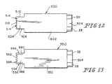
- biosensor 10 can be manufactured in a variety of shapes and sizes. Non-limiting examples of which are illustrated in Figs. 4-13. Each of the biosensors illustrated in Figs. 4-13 are formed similarly to biosensor 10, except for the shape of their tabs.
- biosensor 110 includes top and bottom plates 112, 114 separated by a spacer 115. Plates 112, 114 are each formed to include a rectangular-shaped tab 116. Tab 116 includes lateral borders 118, 120 and an end 122. Illustratively, borders 118, 120 are generally parallel relative to one another and have a first dimension 124 that is greater than the second dimension 126 of end 122. It is appreciated that the relative dimensions between first and second dimensions 124, 126 may vary in accordance with this disclosure so long as first dimension 124 is greater than second dimension 126.
- biosensor 150 includes top and bottom plates 152, 154 separated by a spacer 164. Plates 152, 154 are each formed to include a curved tab 156. Tab 156 includes curved lateral borders 158, 160 that meet at an end 162. It is appreciated that borders 158, 160 can be formed with a variety of degrees of curvature in accordance with this disclosure.
- Biosensor 200 is provided in accordance with another aspect of this invention and is illustrated in Fig. 6.
- Biosensor 200 includes top and bottom plates 212, 214 separated by a spacer 224. Plates 212, 214 are each formed to include a tab 216.
- Tab 216 includes lateral borders 218, 220 and an end 222.
- borders 218, 220 diverge toward end 222. It is appreciated that borders 218, 220 can be formed to have a variety of degrees of divergence relative to one another in accordance with this disclosure.
- Biosensor 250 is shown in Fig. 7 and includes top and bottom plates 252, 254 separated by a spacer 264. Plates 252, 254 are each formed to include a tab 256. Tab 256 includes generally straight lateral borders 258, 260 and an end 262. Borders are positioned generally parallel relative to one another and end 262 is generally concave in shape. It is appreciated that end 262 with a variety of degrees of curvature, or may be indented in any number of manners in accordance with the disclosure.
- biosensor 300 includes top and bottom plates 312, 314, which are separated from one another by a spacer 316.
- Each plate 312, 314 has opposite ends 318, 320 and opposite lateral borders 322, 324. Additionally, ends 320 and a portion 326 of lateral borders 322, 324 define a fluid sample-receiving portion in communication with the capillary space. It is appreciated that the length of portion 326 of lateral borders 322, 324 may vary in accordance with this disclosure.
- biosensor 350 includes top and bottom plates 352, 354, which are separated from one another by a spacer 368. Plates 352, 354 are each formed to include a tab 356. Tab 356 includes lateral borders 358, 360 that include a first tapered portion 362 and a second portion 364 extending between tapered portion 362 and an end 366. It is appreciated that the angle of first taper portion 362 as well as the length of second portion 364 can vary in accordance with this disclosure.
- biosensor 400 includes top and bottom plates 412, 414, which are separated from one another by a spacer (not shown). Plates 412, 414 are each formed to include a tab 416. Tab 416 includes lateral borders 418, 420 that converge toward end 422. It is appreciated that borders 418, 420 can converge toward one another at a variety of angles in accordance with this disclosure.
- Biosensor 450 includes a top plate 452 and a bottom plate (not shown), which are separated from one another by a spacer 456. Each plate has a concave-shaped first end 458 and opposite lateral borders 460, 462. Additionally, ends 458 and a portion 464 of lateral borders 460, 462 define a fluid sample-receiving portion in communication with the capillary space.
- Biosensor 500 includes a top plate 502 and a bottom plate 504, which are separated from one another by a spacer (not shown). Plates 502, 504 are each formed to include a tab 506. Tab 506 includes lateral borders 508, 510, and a free end 512. End 512 includes a plurality of V-shaped notches 514 therein. It is appreciated end 512 can include any number of notches formed in a variety of shapes and sizes in accordance with this disclosure.
- Biosensor 550 includes a top plate 552 and a bottom plate 554, which are separated from one another by a spacer (not shown). Plates 550, 552 are each formed to include a tab 556. Tab 556 includes lateral borders 558, 560, and a free end 562. Borders 558, 560 and end 562 include a plurality of concave notches 564 therein. It is appreciated borders 558, 560 and end 562 can each include any number of notches formed in a variety of shapes and sizes in accordance with this disclosure.
Abstract
Description
| Analyte | Enzymes | Mediator (Oxidized Form) | Additional Mediator |
| Glucose | Glucose Dehydrogenase and Diaphorase | Ferricyanide | |
| Glucose | Glucose-Dehydrogenase (Quinoprotein) | Ferricyanide | |
| Cholesterol | Cholesterol Esterase and Cholesterol Oxidase | Ferricyanide | 2,6-Dimethyl-1,4-Benzoquinone 2,5-Dichloro-1,4-Benzoquinone or Phenazine Ethosulfate |
| HDL Cholesterol | Cholesterol Esterase and Cholesterol Oxidase | Ferricyanide | 2,6-Dimethyl-1,4-Benzoquinone 2,5-Dichloro-1,4-Benzoquinone or Phenazine Ethosulfate |
| Triglycerides | Lipoprotein Lipase, Glycerol Kinase, and Glycerol-3-Phosphate Oxidase | Ferricyanide or Phenazine Ethosulfate | Phenazine Methosulfate |
| Lactate | Lactate Oxidase | Ferricyanide | 2,6-Dichloro-1,4-Benzoquinone |
| Lactate | Lactate Dehydrogenase and Diaphorase | Ferricyanide Phenazine Ethosulfate, or Phenazine Methosulfate | |
| Lactate Dehydrogenase | Diaphorase | Ferricyanide | Phenazine Ethosulfate, or Phenazine Methosulfate |
| Pyruvate | Pyruvate Oxidase | Ferricyanide | |
| Alcohol | Alcohol Oxidase | Phenylenediamine | |
| Bilirubin | Bilirubin Oxidase | 1-Methoxy-Phenazine Methosulfate | |
| Uric Acid | Uricase | Ferricyanide |
Claims (20)
- A biosensor comprising:first and second plate elements, said plate elements having first and second ends and first and second lateral borders,a spacer positioned to lie between the first and second plate elements so that at least a portion of the first and second plate elements cooperate with one another to form opposite walls of a capillary space and the first ends and at least a portion of the opposite lateral borders define a fluid sample receiving portion in communication with the capillary space, andelectrodes positioned in the capillary space.
- The biosensor of claim 1, wherein the lateral borders are straight.
- The biosensor of claim 2, wherein the lateral borders are parallel relative to one another.
- The biosensor of claim 2, wherein the lateral borders converge toward the first ends.
- The biosensor of claim 1, wherein the lateral borders are curved.
- The biosensor of claim 1, wherein the spacer is an adhesive.
- The biosensor of claim 1, where the ends of the first and second plate elements are off-set from one another.
- The biosensor of claim 7, wherein the ends of the first and second plate elements are parallel relative to one another.
- A biosensor comprising:first and second plate elements, said plate elements having tabs with ends and first andsecond lateral borders,electrodes positioned on the tab of said first plate element, anda spacer positioned to lie between the plate elements so that the tabs form opposite walls of a capillary space extending between lateral borders and ends, wherein the ends andlateral borders cooperate to define a fluid sample receiving portion in communication with the capillary space.
- The biosensor of claim 9, wherein the tabs are rectangular in shape.
- The biosensor of claim 10, wherein the ends of the first and second plate elements are off-set relative to one another.
- The biosensor of claim 11, wherein the lateral borders are the same length as the ends.
- The biosensor of claim 9, wherein the tabs are triangular in shape.
- The biosensor of claim 9, wherein the tabs are curved.
- A biosensor comprising:first and second plate elements, said plate elements including body portions with edges having a first dimension and opposite ends and tabs extending from one of the opposite ends, the tabs including lateral borders having a second dimension, which is less than the first dimension,electrodes positioned between the tabs, anda spacer positioned to lie between the edges of the body portions so that the tabs form opposite walls of a capillary space, wherein the tabs cooperate to define a fluid sample receiving portion in communication with the capillary space.
- The biosensor of claim 15, wherein the lateral borders are straight.
- The biosensor of claim 16, wherein the tabs are rectangular in shape.
- The biosensor of claim 15, wherein the tabs are triangular in shape.
- The biosensor of claim 16, wherein the tabs include ends and the ends of the tab have a third dimension that is equal to the second dimension.
- The biosensor of claim 15, wherein the lateral borders are curved.
Priority Applications (1)
| Application Number | Priority Date | Filing Date | Title |
|---|---|---|---|
| EP14003168.3A EP2824188A3 (en) | 2000-12-04 | 2001-11-30 | Biosensor |
Applications Claiming Priority (2)
| Application Number | Priority Date | Filing Date | Title |
|---|---|---|---|
| US729296 | 2000-12-04 | ||
| US09/729,296 US6447657B1 (en) | 2000-12-04 | 2000-12-04 | Biosensor |
Related Child Applications (1)
| Application Number | Title | Priority Date | Filing Date |
|---|---|---|---|
| EP14003168.3A Division EP2824188A3 (en) | 2000-12-04 | 2001-11-30 | Biosensor |
Publications (2)
| Publication Number | Publication Date |
|---|---|
| EP1211321A1 true EP1211321A1 (en) | 2002-06-05 |
| EP1211321B1 EP1211321B1 (en) | 2014-09-17 |
Family
ID=24930400
Family Applications (2)
| Application Number | Title | Priority Date | Filing Date |
|---|---|---|---|
| EP14003168.3A Withdrawn EP2824188A3 (en) | 2000-12-04 | 2001-11-30 | Biosensor |
| EP01128577.2A Expired - Lifetime EP1211321B1 (en) | 2000-12-04 | 2001-11-30 | Biosensor |
Family Applications Before (1)
| Application Number | Title | Priority Date | Filing Date |
|---|---|---|---|
| EP14003168.3A Withdrawn EP2824188A3 (en) | 2000-12-04 | 2001-11-30 | Biosensor |
Country Status (3)
| Country | Link |
|---|---|
| US (1) | US6447657B1 (en) |
| EP (2) | EP2824188A3 (en) |
| JP (1) | JP3672525B2 (en) |
Cited By (10)
| Publication number | Priority date | Publication date | Assignee | Title |
|---|---|---|---|---|
| EP1302545A3 (en) * | 2001-10-09 | 2003-11-05 | Roche Diagnostics GmbH | Enzyme Biosensor |
| WO2007038464A1 (en) * | 2005-09-27 | 2007-04-05 | Abbott Diabetes Care, Inc. | In vitro analyte sensor and methods of use |
| EP1813937A1 (en) * | 2006-01-25 | 2007-08-01 | Roche Diagnostics GmbH | Electrochemical biosensor analysis system |
| WO2007100800A1 (en) * | 2006-02-28 | 2007-09-07 | Abbott Diabetes Care Inc. | Biosensor |
| WO2007126920A1 (en) * | 2006-03-29 | 2007-11-08 | Abbott Diabetes Care Inc. | Analyte sensors and methods comprising dose sufficiency electrodes |
| WO2009106906A1 (en) * | 2008-02-27 | 2009-09-03 | Budapesti Müszaki És Gazdaságtudományi Egyetem | Interdigitated electrode |
| WO2010072601A1 (en) * | 2008-12-22 | 2010-07-01 | Endress+Hauser Conducta Gesellschaft Für Mess- Und Regeltechnik Mbh+Co. Kg | Measuring probe for electrochemical measurements |
| US7905999B2 (en) | 2005-06-08 | 2011-03-15 | Abbott Laboratories | Biosensor strips and methods of preparing same |
| US7922883B2 (en) | 2005-06-08 | 2011-04-12 | Abbott Laboratories | Biosensors and methods of using the same |
| EP2407775A1 (en) * | 2010-07-12 | 2012-01-18 | Arkray, Inc. | Biosensor and biosensor manufacturing method |
Families Citing this family (51)
| Publication number | Priority date | Publication date | Assignee | Title |
|---|---|---|---|---|
| US8071384B2 (en) | 1997-12-22 | 2011-12-06 | Roche Diagnostics Operations, Inc. | Control and calibration solutions and methods for their use |
| US20050103624A1 (en) | 1999-10-04 | 2005-05-19 | Bhullar Raghbir S. | Biosensor and method of making |
| US6848970B2 (en) * | 2002-09-16 | 2005-02-01 | Applied Materials, Inc. | Process control in electrochemically assisted planarization |
| US7473398B2 (en) * | 2001-05-25 | 2009-01-06 | Roche Diagnostics Operations, Inc. | Biosensor |
| EP2290358B1 (en) * | 2001-07-27 | 2015-11-11 | ARKRAY, Inc. | Analyzing instrument |
| US20030113622A1 (en) * | 2001-12-14 | 2003-06-19 | Blasi Jane A. | Electrolyte additive for non-aqueous electrochemical cells |
| US7727367B2 (en) * | 2002-08-13 | 2010-06-01 | Gunze Limited | Biosensor and method for manufacturing same |
| AT411627B (en) * | 2002-08-23 | 2004-03-25 | Hoffmann La Roche | DEVICE FOR CHECKING THE POSITIONING AND BUBBLE CLEARANCE OF A MEDICAL MICRO SAMPLE IN A FLOW MEASURING CELL |
| US7144485B2 (en) * | 2003-01-13 | 2006-12-05 | Hmd Biomedical Inc. | Strips for analyzing samples |
| JP4762137B2 (en) * | 2003-04-28 | 2011-08-31 | アーマッド,ルブナ・エム | Thermoelectric biosensor for analysis in gas |
| US20040251132A1 (en) * | 2003-06-06 | 2004-12-16 | Leach Christopher Philip | Reduced volume strip |
| US7462265B2 (en) * | 2003-06-06 | 2008-12-09 | Lifescan, Inc. | Reduced volume electrochemical sensor |
| JP2007524816A (en) | 2003-06-20 | 2007-08-30 | エフ ホフマン−ラ ロッシュ アクチェン ゲゼルシャフト | Method for producing thin uniform reagent strip and its reagent |
| US8071030B2 (en) | 2003-06-20 | 2011-12-06 | Roche Diagnostics Operations, Inc. | Test strip with flared sample receiving chamber |
| US8058077B2 (en) | 2003-06-20 | 2011-11-15 | Roche Diagnostics Operations, Inc. | Method for coding information on a biosensor test strip |
| US7452457B2 (en) | 2003-06-20 | 2008-11-18 | Roche Diagnostics Operations, Inc. | System and method for analyte measurement using dose sufficiency electrodes |
| US8148164B2 (en) | 2003-06-20 | 2012-04-03 | Roche Diagnostics Operations, Inc. | System and method for determining the concentration of an analyte in a sample fluid |
| US7488601B2 (en) | 2003-06-20 | 2009-02-10 | Roche Diagnostic Operations, Inc. | System and method for determining an abused sensor during analyte measurement |
| US7645421B2 (en) | 2003-06-20 | 2010-01-12 | Roche Diagnostics Operations, Inc. | System and method for coding information on a biosensor test strip |
| US8679853B2 (en) | 2003-06-20 | 2014-03-25 | Roche Diagnostics Operations, Inc. | Biosensor with laser-sealed capillary space and method of making |
| US8206565B2 (en) | 2003-06-20 | 2012-06-26 | Roche Diagnostics Operation, Inc. | System and method for coding information on a biosensor test strip |
| US7718439B2 (en) | 2003-06-20 | 2010-05-18 | Roche Diagnostics Operations, Inc. | System and method for coding information on a biosensor test strip |
| US7645373B2 (en) | 2003-06-20 | 2010-01-12 | Roche Diagnostic Operations, Inc. | System and method for coding information on a biosensor test strip |
| EP1667581A1 (en) * | 2003-09-01 | 2006-06-14 | Inverness Medical Switzerland GmbH | Sampling device with capillary action |
| BRPI0507376A (en) | 2004-02-06 | 2007-07-10 | Bayer Healthcare Llc | oxidizable species as an internal reference for biosensors and method of use |
| US20050247573A1 (en) * | 2004-03-23 | 2005-11-10 | Hideaki Nakamura | Biosensors |
| CN103954668B (en) * | 2004-05-21 | 2016-11-23 | 埃葛梅崔克斯股份有限公司 | Electrochemical cell and the method producing electrochemical cell |
| US7569126B2 (en) | 2004-06-18 | 2009-08-04 | Roche Diagnostics Operations, Inc. | System and method for quality assurance of a biosensor test strip |
| CN101151526B (en) * | 2005-03-29 | 2012-05-30 | Cci株式会社 | Biosensor |
| US8192599B2 (en) * | 2005-05-25 | 2012-06-05 | Universal Biosensors Pty Ltd | Method and apparatus for electrochemical analysis |
| US8323464B2 (en) * | 2005-05-25 | 2012-12-04 | Universal Biosensors Pty Ltd | Method and apparatus for electrochemical analysis |
| CN103558284B (en) | 2005-07-20 | 2017-04-12 | 安晟信医疗科技控股公司 | Gated amperometry |
| US20070062811A1 (en) * | 2005-09-21 | 2007-03-22 | Health & Life Co., Ltd | Bioelectrochemical sensor strip capable of taking trace samples |
| CN101273266B (en) | 2005-09-30 | 2012-08-22 | 拜尔健康护理有限责任公司 | Gated voltammetry |
| US7955484B2 (en) * | 2005-12-14 | 2011-06-07 | Nova Biomedical Corporation | Glucose biosensor and method |
| US7807143B2 (en) * | 2006-10-18 | 2010-10-05 | Research Development Foundation | Alpha-MSH therapies for treatment of autoimmune disease |
| JP4811267B2 (en) * | 2006-12-22 | 2011-11-09 | パナソニック株式会社 | Microchip and analytical device using the same |
| US7802467B2 (en) * | 2006-12-22 | 2010-09-28 | Abbott Diabetes Care Inc. | Analyte sensors and methods of use |
| US20080197018A1 (en) * | 2007-02-16 | 2008-08-21 | Jin Han | Device with a pre-defined and guided capillary fill design |
| WO2009076302A1 (en) | 2007-12-10 | 2009-06-18 | Bayer Healthcare Llc | Control markers for auto-detection of control solution and methods of use |
| JP5405916B2 (en) * | 2008-06-24 | 2014-02-05 | パナソニック株式会社 | Biosensor, method for manufacturing the same, and detection system including the same |
| EP2345893B1 (en) | 2008-11-04 | 2016-05-04 | Panasonic Healthcare Holdings Co., Ltd. | Measurement device, measurement method, and program |
| KR101147534B1 (en) * | 2009-06-02 | 2012-05-21 | 주식회사 인포피아 | Device for collecting body fluid |
| US8992750B1 (en) | 2012-07-02 | 2015-03-31 | Roche Diagnostics Operations, Inc. | Biosensor and methods for manufacturing |
| CN105247356B (en) | 2013-03-15 | 2017-11-07 | 豪夫迈·罗氏有限公司 | Use the method and the unit and system of merging methods described of the information of the recovery pulse in being measured from electrochemical analyte |
| JP6412027B2 (en) | 2013-03-15 | 2018-10-24 | エフ.ホフマン−ラ ロシュ アーゲーF. Hoffmann−La Roche Aktiengesellschaft | Method for fail-safe electrochemical measurement of analyte and device, apparatus and system incorporating the same |
| KR101727447B1 (en) | 2013-03-15 | 2017-04-14 | 에프. 호프만-라 로슈 아게 | Methods of scaling data used to construct biosensor algorithms as well as devices, apparatuses and systems incorporating the same |
| CA2900572C (en) | 2013-03-15 | 2018-02-13 | F. Hoffmann-La Roche Ag | Methods of detecting high antioxidant levels during electrochemical measurements and failsafing an analyte concentration therefrom as well as devices, apparatuses and systems incorporting the same |
| WO2016073395A1 (en) * | 2014-11-03 | 2016-05-12 | Roche Diabetes Care, Inc. | Electrode arrangements for electrochemical test elements and methods of use thereof |
| JP2019529935A (en) | 2016-10-05 | 2019-10-17 | エフ ホフマン−ラ ロッシュ アクチェン ゲゼルシャフト | Detection reagents and electrode arrangements for multi-sample diagnostic test elements and methods of using them |
| EP3647774B1 (en) | 2018-10-31 | 2022-05-04 | Roche Diabetes Care GmbH | Devices and method for measuring an analyte concentration in a sample of bodily fluid |
Citations (5)
| Publication number | Priority date | Publication date | Assignee | Title |
|---|---|---|---|---|
| US5437999A (en) * | 1994-02-22 | 1995-08-01 | Boehringer Mannheim Corporation | Electrochemical sensor |
| EP0851224A1 (en) * | 1996-12-24 | 1998-07-01 | Matsushita Electric Industrial Co., Ltd. | Biosensor with C-shaped counter electrode |
| US5798031A (en) * | 1997-05-12 | 1998-08-25 | Bayer Corporation | Electrochemical biosensor |
| JPH11125618A (en) * | 1997-08-22 | 1999-05-11 | Nok Corp | Biosensor |
| EP0964059A2 (en) * | 1998-06-11 | 1999-12-15 | Matsushita Electric Industrial Co., Ltd. | Biosensor |
Family Cites Families (24)
| Publication number | Priority date | Publication date | Assignee | Title |
|---|---|---|---|---|
| US5141868A (en) | 1984-06-13 | 1992-08-25 | Internationale Octrooi Maatschappij "Octropa" Bv | Device for use in chemical test procedures |
| DE68924026T3 (en) | 1988-03-31 | 2008-01-10 | Matsushita Electric Industrial Co., Ltd., Kadoma | BIOSENSOR AND ITS MANUFACTURE. |
| US4999632A (en) | 1989-12-15 | 1991-03-12 | Boehringer Mannheim Corporation | Analog to digital conversion with noise reduction |
| US4999582A (en) | 1989-12-15 | 1991-03-12 | Boehringer Mannheim Corp. | Biosensor electrode excitation circuit |
| US4963814A (en) | 1989-12-15 | 1990-10-16 | Boehringer Mannheim Corporation | Regulated bifurcated power supply |
| US5243516A (en) | 1989-12-15 | 1993-09-07 | Boehringer Mannheim Corporation | Biosensing instrument and method |
| US5320732A (en) | 1990-07-20 | 1994-06-14 | Matsushita Electric Industrial Co., Ltd. | Biosensor and measuring apparatus using the same |
| US5264103A (en) | 1991-10-18 | 1993-11-23 | Matsushita Electric Industrial Co., Ltd. | Biosensor and a method for measuring a concentration of a substrate in a sample |
| US5385846A (en) | 1993-06-03 | 1995-01-31 | Boehringer Mannheim Corporation | Biosensor and method for hematocrit determination |
| CA2153883C (en) | 1993-06-08 | 1999-02-09 | Bradley E. White | Biosensing meter which detects proper electrode engagement and distinguishes sample and check strips |
| US5405511A (en) | 1993-06-08 | 1995-04-11 | Boehringer Mannheim Corporation | Biosensing meter with ambient temperature estimation method and system |
| US5366609A (en) | 1993-06-08 | 1994-11-22 | Boehringer Mannheim Corporation | Biosensing meter with pluggable memory key |
| US5352351A (en) | 1993-06-08 | 1994-10-04 | Boehringer Mannheim Corporation | Biosensing meter with fail/safe procedures to prevent erroneous indications |
| US5413690A (en) | 1993-07-23 | 1995-05-09 | Boehringer Mannheim Corporation | Potentiometric biosensor and the method of its use |
| US5762770A (en) | 1994-02-21 | 1998-06-09 | Boehringer Mannheim Corporation | Electrochemical biosensor test strip |
| JP3365184B2 (en) * | 1996-01-10 | 2003-01-08 | 松下電器産業株式会社 | Biosensor |
| US6071391A (en) * | 1997-09-12 | 2000-06-06 | Nok Corporation | Enzyme electrode structure |
| TR200000921T2 (en) | 1997-10-07 | 2000-07-21 | Ucb Bioproducts, S.A. | Assay device for determining analytes in a liquid dairy product |
| US5997817A (en) | 1997-12-05 | 1999-12-07 | Roche Diagnostics Corporation | Electrochemical biosensor test strip |
| US5975153A (en) * | 1998-02-13 | 1999-11-02 | Roche Diagnostics Corporation | Capillary fill test device with improved fluid delivery |
| DE19815684A1 (en) * | 1998-04-08 | 1999-10-14 | Roche Diagnostics Gmbh | Process for the preparation of analytical aids |
| US6338790B1 (en) * | 1998-10-08 | 2002-01-15 | Therasense, Inc. | Small volume in vitro analyte sensor with diffusible or non-leachable redox mediator |
| US6258229B1 (en) | 1999-06-02 | 2001-07-10 | Handani Winarta | Disposable sub-microliter volume sensor and method of making |
| US6287451B1 (en) | 1999-06-02 | 2001-09-11 | Handani Winarta | Disposable sensor and method of making |
-
2000
- 2000-12-04 US US09/729,296 patent/US6447657B1/en not_active Expired - Lifetime
-
2001
- 2001-11-29 JP JP2001365062A patent/JP3672525B2/en not_active Expired - Lifetime
- 2001-11-30 EP EP14003168.3A patent/EP2824188A3/en not_active Withdrawn
- 2001-11-30 EP EP01128577.2A patent/EP1211321B1/en not_active Expired - Lifetime
Patent Citations (5)
| Publication number | Priority date | Publication date | Assignee | Title |
|---|---|---|---|---|
| US5437999A (en) * | 1994-02-22 | 1995-08-01 | Boehringer Mannheim Corporation | Electrochemical sensor |
| EP0851224A1 (en) * | 1996-12-24 | 1998-07-01 | Matsushita Electric Industrial Co., Ltd. | Biosensor with C-shaped counter electrode |
| US5798031A (en) * | 1997-05-12 | 1998-08-25 | Bayer Corporation | Electrochemical biosensor |
| JPH11125618A (en) * | 1997-08-22 | 1999-05-11 | Nok Corp | Biosensor |
| EP0964059A2 (en) * | 1998-06-11 | 1999-12-15 | Matsushita Electric Industrial Co., Ltd. | Biosensor |
Non-Patent Citations (1)
| Title |
|---|
| PATENT ABSTRACTS OF JAPAN vol. 1999, no. 10 31 August 1999 (1999-08-31) * |
Cited By (30)
| Publication number | Priority date | Publication date | Assignee | Title |
|---|---|---|---|---|
| EP1302545A3 (en) * | 2001-10-09 | 2003-11-05 | Roche Diagnostics GmbH | Enzyme Biosensor |
| US6755949B1 (en) | 2001-10-09 | 2004-06-29 | Roche Diagnostics Corporation | Biosensor |
| US8241486B2 (en) | 2005-06-08 | 2012-08-14 | Abbott Laboratories | Biosensors and methods of preparing same |
| US7922883B2 (en) | 2005-06-08 | 2011-04-12 | Abbott Laboratories | Biosensors and methods of using the same |
| US9063076B2 (en) | 2005-06-08 | 2015-06-23 | Abbott Diabetes Care Inc. | Biosensors |
| US8652320B2 (en) | 2005-06-08 | 2014-02-18 | Abbott Laboratories | Biosensors and methods of preparing same |
| US7905999B2 (en) | 2005-06-08 | 2011-03-15 | Abbott Laboratories | Biosensor strips and methods of preparing same |
| US9535028B2 (en) | 2005-06-08 | 2017-01-03 | Abbott Diabetes Care Inc. | Biosensors and methods of preparing same |
| US7993505B2 (en) | 2005-09-27 | 2011-08-09 | Abbot Diabetes Care Inc. | In vitro analyte sensor and methods of use |
| US7846311B2 (en) | 2005-09-27 | 2010-12-07 | Abbott Diabetes Care Inc. | In vitro analyte sensor and methods of use |
| WO2007038464A1 (en) * | 2005-09-27 | 2007-04-05 | Abbott Diabetes Care, Inc. | In vitro analyte sensor and methods of use |
| CN101371133B (en) * | 2006-01-25 | 2012-07-04 | 霍夫曼-拉罗奇有限公司 | Electrochemical biosensor analysis system |
| WO2007085353A1 (en) * | 2006-01-25 | 2007-08-02 | Roche Diagnostics Gmbh | Electrochemical biosensor analysis system |
| EP1813937A1 (en) * | 2006-01-25 | 2007-08-01 | Roche Diagnostics GmbH | Electrochemical biosensor analysis system |
| US8357274B2 (en) | 2006-01-25 | 2013-01-22 | Roche Diagnostics Operations, Inc. | Electrochemical biosensor analysis system |
| US7811430B2 (en) | 2006-02-28 | 2010-10-12 | Abbott Diabetes Care Inc. | Biosensors and methods of making |
| US7811432B2 (en) | 2006-02-28 | 2010-10-12 | Abbott Diabetes Care Inc. | Biosensors and methods of making |
| WO2007100800A1 (en) * | 2006-02-28 | 2007-09-07 | Abbott Diabetes Care Inc. | Biosensor |
| US8414762B2 (en) | 2006-02-28 | 2013-04-09 | Abbott Diabetes Care Inc. | Biosensors and methods of making |
| US8211280B2 (en) | 2006-02-28 | 2012-07-03 | Abbott Diabetes Care Inc. | Biosensors and methods of making |
| US8083927B2 (en) | 2006-03-29 | 2011-12-27 | Abbott Diabetes Care Inc. | Analyte sensors and methods of use |
| US7887682B2 (en) | 2006-03-29 | 2011-02-15 | Abbott Diabetes Care Inc. | Analyte sensors and methods of use |
| US8419927B2 (en) | 2006-03-29 | 2013-04-16 | Abbott Diabetes Care Inc. | Analyte sensors and methods of use |
| WO2007126920A1 (en) * | 2006-03-29 | 2007-11-08 | Abbott Diabetes Care Inc. | Analyte sensors and methods comprising dose sufficiency electrodes |
| WO2009106906A1 (en) * | 2008-02-27 | 2009-09-03 | Budapesti Müszaki És Gazdaságtudományi Egyetem | Interdigitated electrode |
| WO2010072601A1 (en) * | 2008-12-22 | 2010-07-01 | Endress+Hauser Conducta Gesellschaft Für Mess- Und Regeltechnik Mbh+Co. Kg | Measuring probe for electrochemical measurements |
| US8920747B2 (en) | 2010-07-12 | 2014-12-30 | Arkray, Inc. | Biosensor and biosensor manufacturing method |
| CN102375051A (en) * | 2010-07-12 | 2012-03-14 | 爱科来株式会社 | Biosensor and biosensor manufacturing method |
| CN102375051B (en) * | 2010-07-12 | 2014-07-30 | 爱科来株式会社 | Biosensor and biosensor manufacturing method |
| EP2407775A1 (en) * | 2010-07-12 | 2012-01-18 | Arkray, Inc. | Biosensor and biosensor manufacturing method |
Also Published As
| Publication number | Publication date |
|---|---|
| US20020100684A1 (en) | 2002-08-01 |
| JP2002214188A (en) | 2002-07-31 |
| EP1211321B1 (en) | 2014-09-17 |
| EP2824188A3 (en) | 2015-07-08 |
| JP3672525B2 (en) | 2005-07-20 |
| US6447657B1 (en) | 2002-09-10 |
| EP2824188A1 (en) | 2015-01-14 |
Similar Documents
| Publication | Publication Date | Title |
|---|---|---|
| US6447657B1 (en) | Biosensor | |
| EP1203956B1 (en) | Biosensor with flow channel | |
| US6814843B1 (en) | Biosensor | |
| US6645359B1 (en) | Biosensor | |
| US7473398B2 (en) | Biosensor | |
| EP1302545B1 (en) | Enzyme Biosensor | |
| US6767440B1 (en) | Biosensor | |
| US6866758B2 (en) | Biosensor | |
| Bhullar et al. | Biosensor |
Legal Events
| Date | Code | Title | Description |
|---|---|---|---|
| PUAI | Public reference made under article 153(3) epc to a published international application that has entered the european phase |
Free format text: ORIGINAL CODE: 0009012 |
|
| AK | Designated contracting states |
Kind code of ref document: A1 Designated state(s): AT BE CH CY DE DK ES FI FR GB GR IE IT LI LU MC NL PT SE TR |
|
| AX | Request for extension of the european patent |
Free format text: AL;LT;LV;MK;RO;SI |
|
| 17P | Request for examination filed |
Effective date: 20021205 |
|
| AKX | Designation fees paid |
Designated state(s): AT BE CH CY DE DK ES FI FR GB GR IE IT LI LU MC NL PT SE TR |
|
| 17Q | First examination report despatched |
Effective date: 20050616 |
|
| 17Q | First examination report despatched |
Effective date: 20050616 |
|
| REG | Reference to a national code |
Ref country code: DE Ref legal event code: R079 Ref document number: 60149016 Country of ref document: DE Free format text: PREVIOUS MAIN CLASS: C12Q0001000000 Ipc: G01N0027327000 |
|
| RIC1 | Information provided on ipc code assigned before grant |
Ipc: G01N 33/487 20060101ALI20140220BHEP Ipc: G01N 27/327 20060101AFI20140220BHEP Ipc: C12Q 1/00 20060101ALI20140220BHEP |
|
| GRAP | Despatch of communication of intention to grant a patent |
Free format text: ORIGINAL CODE: EPIDOSNIGR1 |
|
| INTG | Intention to grant announced |
Effective date: 20140416 |
|
| RIN1 | Information on inventor provided before grant (corrected) |
Inventor name: HILL, BRIAN S. Inventor name: WILSEY, CHRISTOPHER D. Inventor name: BHULLAR, RAGHBIR SINGH |
|
| GRAS | Grant fee paid |
Free format text: ORIGINAL CODE: EPIDOSNIGR3 |
|
| GRAA | (expected) grant |
Free format text: ORIGINAL CODE: 0009210 |
|
| RAP1 | Party data changed (applicant data changed or rights of an application transferred) |
Owner name: F. HOFFMANN-LA ROCHE AG Owner name: ROCHE DIAGNOSTICS GMBH |
|
| AK | Designated contracting states |
Kind code of ref document: B1 Designated state(s): AT BE CH CY DE DK ES FI FR GB GR IE IT LI LU MC NL PT SE TR |
|
| REG | Reference to a national code |
Ref country code: GB Ref legal event code: FG4D |
|
| REG | Reference to a national code |
Ref country code: DE Ref legal event code: R081 Ref document number: 60149016 Country of ref document: DE Owner name: ROCHE DIABETES CARE GMBH, DE Free format text: FORMER OWNERS: ROCHE DIAGNOSTICS GMBH, 68305 MANNHEIM, DE; F. HOFFMANN-LA ROCHE AG, 4070 BASEL, CH |
|
| REG | Reference to a national code |
Ref country code: CH Ref legal event code: EP |
|
| REG | Reference to a national code |
Ref country code: IE Ref legal event code: FG4D |
|
| REG | Reference to a national code |
Ref country code: AT Ref legal event code: REF Ref document number: 687920 Country of ref document: AT Kind code of ref document: T Effective date: 20141015 |
|
| REG | Reference to a national code |
Ref country code: DE Ref legal event code: R096 Ref document number: 60149016 Country of ref document: DE Effective date: 20141030 |
|
| PG25 | Lapsed in a contracting state [announced via postgrant information from national office to epo] |
Ref country code: SE Free format text: LAPSE BECAUSE OF FAILURE TO SUBMIT A TRANSLATION OF THE DESCRIPTION OR TO PAY THE FEE WITHIN THE PRESCRIBED TIME-LIMIT Effective date: 20140917 Ref country code: FI Free format text: LAPSE BECAUSE OF FAILURE TO SUBMIT A TRANSLATION OF THE DESCRIPTION OR TO PAY THE FEE WITHIN THE PRESCRIBED TIME-LIMIT Effective date: 20140917 Ref country code: GR Free format text: LAPSE BECAUSE OF FAILURE TO SUBMIT A TRANSLATION OF THE DESCRIPTION OR TO PAY THE FEE WITHIN THE PRESCRIBED TIME-LIMIT Effective date: 20141218 |
|
| REG | Reference to a national code |
Ref country code: NL Ref legal event code: VDEP Effective date: 20140917 |
|
| PG25 | Lapsed in a contracting state [announced via postgrant information from national office to epo] |
Ref country code: CY Free format text: LAPSE BECAUSE OF FAILURE TO SUBMIT A TRANSLATION OF THE DESCRIPTION OR TO PAY THE FEE WITHIN THE PRESCRIBED TIME-LIMIT Effective date: 20140917 |
|
| REG | Reference to a national code |
Ref country code: AT Ref legal event code: MK05 Ref document number: 687920 Country of ref document: AT Kind code of ref document: T Effective date: 20140917 |
|
| PG25 | Lapsed in a contracting state [announced via postgrant information from national office to epo] |
Ref country code: NL Free format text: LAPSE BECAUSE OF FAILURE TO SUBMIT A TRANSLATION OF THE DESCRIPTION OR TO PAY THE FEE WITHIN THE PRESCRIBED TIME-LIMIT Effective date: 20140917 |
|
| PG25 | Lapsed in a contracting state [announced via postgrant information from national office to epo] |
Ref country code: PT Free format text: LAPSE BECAUSE OF FAILURE TO SUBMIT A TRANSLATION OF THE DESCRIPTION OR TO PAY THE FEE WITHIN THE PRESCRIBED TIME-LIMIT Effective date: 20150119 Ref country code: ES Free format text: LAPSE BECAUSE OF FAILURE TO SUBMIT A TRANSLATION OF THE DESCRIPTION OR TO PAY THE FEE WITHIN THE PRESCRIBED TIME-LIMIT Effective date: 20140917 |
|
| PG25 | Lapsed in a contracting state [announced via postgrant information from national office to epo] |
Ref country code: AT Free format text: LAPSE BECAUSE OF FAILURE TO SUBMIT A TRANSLATION OF THE DESCRIPTION OR TO PAY THE FEE WITHIN THE PRESCRIBED TIME-LIMIT Effective date: 20140917 |
|
| REG | Reference to a national code |
Ref country code: DE Ref legal event code: R097 Ref document number: 60149016 Country of ref document: DE |
|
| PG25 | Lapsed in a contracting state [announced via postgrant information from national office to epo] |
Ref country code: MC Free format text: LAPSE BECAUSE OF FAILURE TO SUBMIT A TRANSLATION OF THE DESCRIPTION OR TO PAY THE FEE WITHIN THE PRESCRIBED TIME-LIMIT Effective date: 20140917 Ref country code: LU Free format text: LAPSE BECAUSE OF FAILURE TO SUBMIT A TRANSLATION OF THE DESCRIPTION OR TO PAY THE FEE WITHIN THE PRESCRIBED TIME-LIMIT Effective date: 20141130 Ref country code: BE Free format text: LAPSE BECAUSE OF NON-PAYMENT OF DUE FEES Effective date: 20141130 |
|
| REG | Reference to a national code |
Ref country code: CH Ref legal event code: PL |
|
| PLBE | No opposition filed within time limit |
Free format text: ORIGINAL CODE: 0009261 |
|
| STAA | Information on the status of an ep patent application or granted ep patent |
Free format text: STATUS: NO OPPOSITION FILED WITHIN TIME LIMIT |
|
| PG25 | Lapsed in a contracting state [announced via postgrant information from national office to epo] |
Ref country code: DK Free format text: LAPSE BECAUSE OF FAILURE TO SUBMIT A TRANSLATION OF THE DESCRIPTION OR TO PAY THE FEE WITHIN THE PRESCRIBED TIME-LIMIT Effective date: 20140917 Ref country code: LI Free format text: LAPSE BECAUSE OF NON-PAYMENT OF DUE FEES Effective date: 20141130 Ref country code: CH Free format text: LAPSE BECAUSE OF NON-PAYMENT OF DUE FEES Effective date: 20141130 |
|
| 26N | No opposition filed |
Effective date: 20150618 |
|
| REG | Reference to a national code |
Ref country code: IE Ref legal event code: MM4A |
|
| REG | Reference to a national code |
Ref country code: FR Ref legal event code: PLFP Year of fee payment: 15 |
|
| PG25 | Lapsed in a contracting state [announced via postgrant information from national office to epo] |
Ref country code: IE Free format text: LAPSE BECAUSE OF NON-PAYMENT OF DUE FEES Effective date: 20141130 |
|
| REG | Reference to a national code |
Ref country code: DE Ref legal event code: R081 Ref document number: 60149016 Country of ref document: DE Owner name: ROCHE DIABETES CARE GMBH, DE Free format text: FORMER OWNER: ROCHE DIAGNOSTICS GMBH, 68305 MANNHEIM, DE |
|
| PG25 | Lapsed in a contracting state [announced via postgrant information from national office to epo] |
Ref country code: TR Free format text: LAPSE BECAUSE OF FAILURE TO SUBMIT A TRANSLATION OF THE DESCRIPTION OR TO PAY THE FEE WITHIN THE PRESCRIBED TIME-LIMIT Effective date: 20140917 |
|
| REG | Reference to a national code |
Ref country code: FR Ref legal event code: PLFP Year of fee payment: 16 |
|
| REG | Reference to a national code |
Ref country code: FR Ref legal event code: PLFP Year of fee payment: 17 |
|
| REG | Reference to a national code |
Ref country code: FR Ref legal event code: PLFP Year of fee payment: 18 |
|
| PGFP | Annual fee paid to national office [announced via postgrant information from national office to epo] |
Ref country code: DE Payment date: 20201013 Year of fee payment: 20 Ref country code: GB Payment date: 20201029 Year of fee payment: 20 Ref country code: IT Payment date: 20201117 Year of fee payment: 20 Ref country code: FR Payment date: 20201023 Year of fee payment: 20 |
|
| REG | Reference to a national code |
Ref country code: DE Ref legal event code: R071 Ref document number: 60149016 Country of ref document: DE |
|
| REG | Reference to a national code |
Ref country code: GB Ref legal event code: PE20 Expiry date: 20211129 |
|
| PG25 | Lapsed in a contracting state [announced via postgrant information from national office to epo] |
Ref country code: GB Free format text: LAPSE BECAUSE OF EXPIRATION OF PROTECTION Effective date: 20211129 |