EP1209668A2 - Magnetic transferring method, and method and apparatus for cleaning magnetic transfer master medium - Google Patents
Magnetic transferring method, and method and apparatus for cleaning magnetic transfer master medium Download PDFInfo
- Publication number
- EP1209668A2 EP1209668A2 EP01127476A EP01127476A EP1209668A2 EP 1209668 A2 EP1209668 A2 EP 1209668A2 EP 01127476 A EP01127476 A EP 01127476A EP 01127476 A EP01127476 A EP 01127476A EP 1209668 A2 EP1209668 A2 EP 1209668A2
- Authority
- EP
- European Patent Office
- Prior art keywords
- medium
- magnetic
- master medium
- master
- transfer
- Prior art date
- Legal status (The legal status is an assumption and is not a legal conclusion. Google has not performed a legal analysis and makes no representation as to the accuracy of the status listed.)
- Withdrawn
Links
- 230000005291 magnetic effect Effects 0.000 title claims abstract description 188
- 238000000034 method Methods 0.000 title claims abstract description 57
- 238000004140 cleaning Methods 0.000 title claims description 35
- 230000001050 lubricating effect Effects 0.000 claims abstract description 18
- 230000015572 biosynthetic process Effects 0.000 claims abstract description 7
- 239000007788 liquid Substances 0.000 claims description 37
- 230000006837 decompression Effects 0.000 claims description 8
- 239000000428 dust Substances 0.000 abstract description 26
- 238000000926 separation method Methods 0.000 abstract description 2
- 238000001179 sorption measurement Methods 0.000 abstract description 2
- 239000010410 layer Substances 0.000 description 70
- 239000000758 substrate Substances 0.000 description 37
- 239000000314 lubricant Substances 0.000 description 18
- 239000010408 film Substances 0.000 description 14
- 239000011248 coating agent Substances 0.000 description 10
- 238000000576 coating method Methods 0.000 description 10
- 239000000696 magnetic material Substances 0.000 description 9
- 239000000463 material Substances 0.000 description 9
- 229920002120 photoresistant polymer Polymers 0.000 description 9
- 239000011347 resin Substances 0.000 description 9
- 229920005989 resin Polymers 0.000 description 9
- 230000008569 process Effects 0.000 description 8
- 230000009467 reduction Effects 0.000 description 8
- 230000005415 magnetization Effects 0.000 description 7
- PXHVJJICTQNCMI-UHFFFAOYSA-N nickel Substances [Ni] PXHVJJICTQNCMI-UHFFFAOYSA-N 0.000 description 7
- 238000007747 plating Methods 0.000 description 7
- 239000011521 glass Substances 0.000 description 6
- 230000001681 protective effect Effects 0.000 description 6
- 238000004544 sputter deposition Methods 0.000 description 5
- 239000010409 thin film Substances 0.000 description 5
- 238000001035 drying Methods 0.000 description 4
- 230000002708 enhancing effect Effects 0.000 description 4
- -1 ester phosphates Chemical class 0.000 description 4
- 230000001965 increasing effect Effects 0.000 description 4
- 238000007733 ion plating Methods 0.000 description 4
- 238000004519 manufacturing process Methods 0.000 description 4
- 230000005499 meniscus Effects 0.000 description 4
- 238000001020 plasma etching Methods 0.000 description 4
- 229920000642 polymer Polymers 0.000 description 4
- 238000003825 pressing Methods 0.000 description 4
- 238000004528 spin coating Methods 0.000 description 4
- 238000001771 vacuum deposition Methods 0.000 description 4
- 238000005406 washing Methods 0.000 description 4
- 229910000684 Cobalt-chrome Inorganic materials 0.000 description 3
- 229910002546 FeCo Inorganic materials 0.000 description 3
- 229910002545 FeCoNi Inorganic materials 0.000 description 3
- 239000010952 cobalt-chrome Substances 0.000 description 3
- 238000005530 etching Methods 0.000 description 3
- 239000003302 ferromagnetic material Substances 0.000 description 3
- 150000002430 hydrocarbons Chemical class 0.000 description 3
- 239000011241 protective layer Substances 0.000 description 3
- XLYOFNOQVPJJNP-UHFFFAOYSA-N water Substances O XLYOFNOQVPJJNP-UHFFFAOYSA-N 0.000 description 3
- 229910001149 41xx steel Inorganic materials 0.000 description 2
- 239000004215 Carbon black (E152) Substances 0.000 description 2
- 229910000531 Co alloy Inorganic materials 0.000 description 2
- 229910002441 CoNi Inorganic materials 0.000 description 2
- 239000005069 Extreme pressure additive Substances 0.000 description 2
- 229910000640 Fe alloy Inorganic materials 0.000 description 2
- 229910000990 Ni alloy Inorganic materials 0.000 description 2
- 229910000943 NiAl Inorganic materials 0.000 description 2
- NPXOKRUENSOPAO-UHFFFAOYSA-N Raney nickel Chemical compound [Al].[Ni] NPXOKRUENSOPAO-UHFFFAOYSA-N 0.000 description 2
- 235000021355 Stearic acid Nutrition 0.000 description 2
- 239000000654 additive Substances 0.000 description 2
- 229910052782 aluminium Inorganic materials 0.000 description 2
- 229920001577 copolymer Polymers 0.000 description 2
- 230000006866 deterioration Effects 0.000 description 2
- 238000003618 dip coating Methods 0.000 description 2
- 238000009826 distribution Methods 0.000 description 2
- 238000005323 electroforming Methods 0.000 description 2
- 150000002148 esters Chemical class 0.000 description 2
- 239000000835 fiber Substances 0.000 description 2
- 244000144992 flock Species 0.000 description 2
- NBVXSUQYWXRMNV-UHFFFAOYSA-N fluoromethane Chemical compound FC NBVXSUQYWXRMNV-UHFFFAOYSA-N 0.000 description 2
- 229930195733 hydrocarbon Natural products 0.000 description 2
- 229910052751 metal Inorganic materials 0.000 description 2
- 239000002184 metal Substances 0.000 description 2
- 239000000203 mixture Substances 0.000 description 2
- GLDOVTGHNKAZLK-UHFFFAOYSA-N octadecan-1-ol Chemical compound CCCCCCCCCCCCCCCCCCO GLDOVTGHNKAZLK-UHFFFAOYSA-N 0.000 description 2
- QIQXTHQIDYTFRH-UHFFFAOYSA-N octadecanoic acid Chemical compound CCCCCCCCCCCCCCCCCC(O)=O QIQXTHQIDYTFRH-UHFFFAOYSA-N 0.000 description 2
- OQCDKBAXFALNLD-UHFFFAOYSA-N octadecanoic acid Natural products CCCCCCCC(C)CCCCCCCCC(O)=O OQCDKBAXFALNLD-UHFFFAOYSA-N 0.000 description 2
- 239000010702 perfluoropolyether Chemical group 0.000 description 2
- 239000010453 quartz Substances 0.000 description 2
- 230000009257 reactivity Effects 0.000 description 2
- VYPSYNLAJGMNEJ-UHFFFAOYSA-N silicon dioxide Inorganic materials O=[Si]=O VYPSYNLAJGMNEJ-UHFFFAOYSA-N 0.000 description 2
- 239000008117 stearic acid Substances 0.000 description 2
- VZGDMQKNWNREIO-UHFFFAOYSA-N tetrachloromethane Chemical compound ClC(Cl)(Cl)Cl VZGDMQKNWNREIO-UHFFFAOYSA-N 0.000 description 2
- ALSTYHKOOCGGFT-KTKRTIGZSA-N (9Z)-octadecen-1-ol Chemical compound CCCCCCCC\C=C/CCCCCCCCO ALSTYHKOOCGGFT-KTKRTIGZSA-N 0.000 description 1
- WRIDQFICGBMAFQ-UHFFFAOYSA-N (E)-8-Octadecenoic acid Natural products CCCCCCCCCC=CCCCCCCC(O)=O WRIDQFICGBMAFQ-UHFFFAOYSA-N 0.000 description 1
- LOUICXNAWQPGSU-UHFFFAOYSA-N 2,2,3,3-tetrafluorooxirane Chemical compound FC1(F)OC1(F)F LOUICXNAWQPGSU-UHFFFAOYSA-N 0.000 description 1
- LQJBNNIYVWPHFW-UHFFFAOYSA-N 20:1omega9c fatty acid Natural products CCCCCCCCCCC=CCCCCCCCC(O)=O LQJBNNIYVWPHFW-UHFFFAOYSA-N 0.000 description 1
- QSBYPNXLFMSGKH-UHFFFAOYSA-N 9-Heptadecensaeure Natural products CCCCCCCC=CCCCCCCCC(O)=O QSBYPNXLFMSGKH-UHFFFAOYSA-N 0.000 description 1
- 241000931526 Acer campestre Species 0.000 description 1
- 239000004925 Acrylic resin Substances 0.000 description 1
- 229920000178 Acrylic resin Polymers 0.000 description 1
- KXDHJXZQYSOELW-UHFFFAOYSA-N Carbamic acid Chemical class NC(O)=O KXDHJXZQYSOELW-UHFFFAOYSA-N 0.000 description 1
- OKTJSMMVPCPJKN-UHFFFAOYSA-N Carbon Chemical compound [C] OKTJSMMVPCPJKN-UHFFFAOYSA-N 0.000 description 1
- 229910015372 FeAl Inorganic materials 0.000 description 1
- 229910005335 FePt Inorganic materials 0.000 description 1
- 229910005435 FeTaN Inorganic materials 0.000 description 1
- 229910001030 Iron–nickel alloy Inorganic materials 0.000 description 1
- REYJJPSVUYRZGE-UHFFFAOYSA-N Octadecylamine Chemical compound CCCCCCCCCCCCCCCCCCN REYJJPSVUYRZGE-UHFFFAOYSA-N 0.000 description 1
- ZQPPMHVWECSIRJ-UHFFFAOYSA-N Oleic acid Natural products CCCCCCCCC=CCCCCCCCC(O)=O ZQPPMHVWECSIRJ-UHFFFAOYSA-N 0.000 description 1
- 239000005642 Oleic acid Substances 0.000 description 1
- 229910019142 PO4 Inorganic materials 0.000 description 1
- NINIDFKCEFEMDL-UHFFFAOYSA-N Sulfur Chemical compound [S] NINIDFKCEFEMDL-UHFFFAOYSA-N 0.000 description 1
- BZHJMEDXRYGGRV-UHFFFAOYSA-N Vinyl chloride Chemical compound ClC=C BZHJMEDXRYGGRV-UHFFFAOYSA-N 0.000 description 1
- 239000002253 acid Substances 0.000 description 1
- 150000001298 alcohols Chemical class 0.000 description 1
- 125000000217 alkyl group Chemical group 0.000 description 1
- 229910045601 alloy Inorganic materials 0.000 description 1
- 239000000956 alloy Substances 0.000 description 1
- XAGFODPZIPBFFR-UHFFFAOYSA-N aluminium Chemical compound [Al] XAGFODPZIPBFFR-UHFFFAOYSA-N 0.000 description 1
- 150000001412 amines Chemical class 0.000 description 1
- 238000004458 analytical method Methods 0.000 description 1
- 125000000484 butyl group Chemical group [H]C([*])([H])C([H])([H])C([H])([H])C([H])([H])[H] 0.000 description 1
- 229910052799 carbon Inorganic materials 0.000 description 1
- 150000004653 carbonic acids Chemical class 0.000 description 1
- IYRWEQXVUNLMAY-UHFFFAOYSA-N carbonyl fluoride Chemical compound FC(F)=O IYRWEQXVUNLMAY-UHFFFAOYSA-N 0.000 description 1
- 239000000919 ceramic Substances 0.000 description 1
- KZIKDWMVGLXOTB-UHFFFAOYSA-N chloranylethene Chemical compound ClC=C.ClC=C KZIKDWMVGLXOTB-UHFFFAOYSA-N 0.000 description 1
- 239000004020 conductor Substances 0.000 description 1
- 239000000356 contaminant Substances 0.000 description 1
- 239000013078 crystal Substances 0.000 description 1
- 238000001723 curing Methods 0.000 description 1
- 230000002950 deficient Effects 0.000 description 1
- 230000005347 demagnetization Effects 0.000 description 1
- 238000007772 electroless plating Methods 0.000 description 1
- 238000001227 electron beam curing Methods 0.000 description 1
- 238000010894 electron beam technology Methods 0.000 description 1
- 238000005516 engineering process Methods 0.000 description 1
- 239000003822 epoxy resin Substances 0.000 description 1
- 230000005294 ferromagnetic effect Effects 0.000 description 1
- 125000003709 fluoroalkyl group Chemical group 0.000 description 1
- 230000004907 flux Effects 0.000 description 1
- 239000011810 insulating material Substances 0.000 description 1
- 229910052742 iron Inorganic materials 0.000 description 1
- QXJSBBXBKPUZAA-UHFFFAOYSA-N isooleic acid Natural products CCCCCCCC=CCCCCCCCCC(O)=O QXJSBBXBKPUZAA-UHFFFAOYSA-N 0.000 description 1
- 238000005304 joining Methods 0.000 description 1
- 238000001459 lithography Methods 0.000 description 1
- 230000005389 magnetism Effects 0.000 description 1
- 230000007246 mechanism Effects 0.000 description 1
- 229910052750 molybdenum Inorganic materials 0.000 description 1
- GOQYKNQRPGWPLP-UHFFFAOYSA-N n-heptadecyl alcohol Natural products CCCCCCCCCCCCCCCCCO GOQYKNQRPGWPLP-UHFFFAOYSA-N 0.000 description 1
- 229910052759 nickel Inorganic materials 0.000 description 1
- 229910052758 niobium Inorganic materials 0.000 description 1
- UHGIMQLJWRAPLT-UHFFFAOYSA-N octadecyl dihydrogen phosphate Chemical compound CCCCCCCCCCCCCCCCCCOP(O)(O)=O UHGIMQLJWRAPLT-UHFFFAOYSA-N 0.000 description 1
- ZQPPMHVWECSIRJ-KTKRTIGZSA-N oleic acid Chemical compound CCCCCCCC\C=C/CCCCCCCC(O)=O ZQPPMHVWECSIRJ-KTKRTIGZSA-N 0.000 description 1
- 229940055577 oleyl alcohol Drugs 0.000 description 1
- XMLQWXUVTXCDDL-UHFFFAOYSA-N oleyl alcohol Natural products CCCCCCC=CCCCCCCCCCCO XMLQWXUVTXCDDL-UHFFFAOYSA-N 0.000 description 1
- 239000003960 organic solvent Substances 0.000 description 1
- 230000000149 penetrating effect Effects 0.000 description 1
- 235000021317 phosphate Nutrition 0.000 description 1
- 150000008301 phosphite esters Chemical class 0.000 description 1
- 150000003014 phosphoric acid esters Chemical class 0.000 description 1
- 238000005498 polishing Methods 0.000 description 1
- 229920003229 poly(methyl methacrylate) Polymers 0.000 description 1
- 229920000515 polycarbonate Polymers 0.000 description 1
- 239000004417 polycarbonate Substances 0.000 description 1
- 229920000647 polyepoxide Polymers 0.000 description 1
- 229920000728 polyester Polymers 0.000 description 1
- 239000004926 polymethyl methacrylate Substances 0.000 description 1
- 229920000098 polyolefin Polymers 0.000 description 1
- 239000000843 powder Substances 0.000 description 1
- 229910052710 silicon Inorganic materials 0.000 description 1
- 239000010703 silicon Substances 0.000 description 1
- 239000002904 solvent Substances 0.000 description 1
- 238000005728 strengthening Methods 0.000 description 1
- 239000000126 substance Substances 0.000 description 1
- 150000003460 sulfonic acids Chemical class 0.000 description 1
- 229910052717 sulfur Inorganic materials 0.000 description 1
- 239000011593 sulfur Substances 0.000 description 1
- 229920003002 synthetic resin Polymers 0.000 description 1
- 239000000057 synthetic resin Substances 0.000 description 1
- 229910052715 tantalum Inorganic materials 0.000 description 1
- 150000003580 thiophosphoric acid esters Chemical class 0.000 description 1
- 229910052719 titanium Inorganic materials 0.000 description 1
- OHRVKCZTBPSUIK-UHFFFAOYSA-N tridodecyl phosphate Chemical compound CCCCCCCCCCCCOP(=O)(OCCCCCCCCCCCC)OCCCCCCCCCCCC OHRVKCZTBPSUIK-UHFFFAOYSA-N 0.000 description 1
- IVIIAEVMQHEPAY-UHFFFAOYSA-N tridodecyl phosphite Chemical compound CCCCCCCCCCCCOP(OCCCCCCCCCCCC)OCCCCCCCCCCCC IVIIAEVMQHEPAY-UHFFFAOYSA-N 0.000 description 1
- JZNDMMGBXUYFNQ-UHFFFAOYSA-N tris(dodecylsulfanyl)phosphane Chemical compound CCCCCCCCCCCCSP(SCCCCCCCCCCCC)SCCCCCCCCCCCC JZNDMMGBXUYFNQ-UHFFFAOYSA-N 0.000 description 1
- 229910052721 tungsten Inorganic materials 0.000 description 1
- 229920002554 vinyl polymer Polymers 0.000 description 1
Images


Classifications
-
- G—PHYSICS
- G11—INFORMATION STORAGE
- G11B—INFORMATION STORAGE BASED ON RELATIVE MOVEMENT BETWEEN RECORD CARRIER AND TRANSDUCER
- G11B5/00—Recording by magnetisation or demagnetisation of a record carrier; Reproducing by magnetic means; Record carriers therefor
- G11B5/86—Re-recording, i.e. transcribing information from one magnetisable record carrier on to one or more similar or dissimilar record carriers
- G11B5/865—Re-recording, i.e. transcribing information from one magnetisable record carrier on to one or more similar or dissimilar record carriers by contact "printing"
-
- G—PHYSICS
- G11—INFORMATION STORAGE
- G11B—INFORMATION STORAGE BASED ON RELATIVE MOVEMENT BETWEEN RECORD CARRIER AND TRANSDUCER
- G11B23/00—Record carriers not specific to the method of recording or reproducing; Accessories, e.g. containers, specially adapted for co-operation with the recording or reproducing apparatus ; Intermediate mediums; Apparatus or processes specially adapted for their manufacture
- G11B23/50—Reconditioning of record carriers; Cleaning of record carriers ; Carrying-off electrostatic charges
- G11B23/505—Reconditioning of record carriers; Cleaning of record carriers ; Carrying-off electrostatic charges of disk carriers
-
- G—PHYSICS
- G11—INFORMATION STORAGE
- G11B—INFORMATION STORAGE BASED ON RELATIVE MOVEMENT BETWEEN RECORD CARRIER AND TRANSDUCER
- G11B5/00—Recording by magnetisation or demagnetisation of a record carrier; Reproducing by magnetic means; Record carriers therefor
- G11B5/48—Disposition or mounting of heads or head supports relative to record carriers ; arrangements of heads, e.g. for scanning the record carrier to increase the relative speed
- G11B5/58—Disposition or mounting of heads or head supports relative to record carriers ; arrangements of heads, e.g. for scanning the record carrier to increase the relative speed with provision for moving the head for the purpose of maintaining alignment of the head relative to the record carrier during transducing operation, e.g. to compensate for surface irregularities of the latter or for track following
- G11B5/596—Disposition or mounting of heads or head supports relative to record carriers ; arrangements of heads, e.g. for scanning the record carrier to increase the relative speed with provision for moving the head for the purpose of maintaining alignment of the head relative to the record carrier during transducing operation, e.g. to compensate for surface irregularities of the latter or for track following for track following on disks
-
- G—PHYSICS
- G11—INFORMATION STORAGE
- G11B—INFORMATION STORAGE BASED ON RELATIVE MOVEMENT BETWEEN RECORD CARRIER AND TRANSDUCER
- G11B5/00—Recording by magnetisation or demagnetisation of a record carrier; Reproducing by magnetic means; Record carriers therefor
- G11B5/84—Processes or apparatus specially adapted for manufacturing record carriers
Definitions
- the present invention relates to a magnetic transferring method for performing magnetic transfer from a master medium bearing information to a slave medium.
- the magnetic transferring method is designed to transfer a magnetic pattern corresponding to information (e.g., servo signal) borne by a master medium by applying a transfer magnetic field while the master medium bearing transfer information by the micro uneven pattern of a magnetic material and a slave medium subjected to the transfer are kept in a state of close contact.
- information e.g., servo signal
- a transfer magnetic field while the master medium bearing transfer information by the micro uneven pattern of a magnetic material and a slave medium subjected to the transfer are kept in a state of close contact.
- the surface of a magnetic recording layer has a lubricating layer formed in order to reduce friction generated by contact with a magnetic head during use.
- the high close contact force between the slave medium and the master medium makes it difficult to separate the slave medium from the master medium after the magnetic transfer. Forcible peeling-off may damage the slave medium or the master medium. If there is dust adsorbed on the lubricating layer of the slave medium during the magnetic transfer, it is difficult to remove the dust in post-treatment because of strong adhesion force. Following the high-speed rotation of the slave medium, the dust may collide with the magnetic head to cause head crashing or dropout. Consequently, an error occurrence rate may be increased.
- the present invention was made in view of the foregoing problems, and it is an object of the invention to provide a magnetic transferring method designed to facilitate the separation of the slave medium from the master medium after the magnetic transfer and prevent the adsorption of dust on the slave medium.
- the close contact state between the slave medium and the master medium affects signal quality after the magnetic transfer.
- a distance between the recording plane of the slave medium and the information bearing plane of the master medium should be set to be less than or equal to 100 nm, and the close contact is required to be in a uniform state on the full surfaces thereof.
- dust may be present between the master medium and the slave medium, and space may be formed between the master medium and the slave medium in the vicinity of the dust depending on the size of the dust, making it impossible to realize a close contact state with a uniform distance across the full surfaces.
- a difference is generated in the transferred magnetic signals in accordance with the above-described distance, reducing signal quality, and generating an intensity distribution in a read out reproducing output.
- the recorded signal is a servo signal
- the tracking function is not sufficient, reducing reliability.
- the dust it was discovered that the sticking of powder dust or the like generated during the manufacturing process of the slave medium to the surface thereof was a main cause.
- the present invention was made in view of the foregoing problems, and it is an object of the invention to provide a magnetic transferring method designed to improve signal quality by making the close contact distance between the slave medium and the master medium uniform during the magnetic transfer.
- the master medium may be contaminated by foreign articles stuck to its surface.
- the foreign articles stuck to the master medium are mainly dust, fiber flocks, and so on, generated in the surrounding environment.
- the repeated close contact between the master medium and the slave medium increases the sticking force of the above-described articles stuck to the surface of the master medium, and equal or more pattern transfer failures occur in all the slave media subjected to the magnetic transfer thereafter. Consequently, many defective products are produced. Further, such stuck articles may deform the surface of the master medium, leading to the loss of its normal function.
- the master medium before the magnetic transfer may be subjected to cleaning carried out by ultrasonic washing using a cleaning solution, wiping or the like.
- the removed articles may be adhered again to the master medium after washing, therefore providing insufficient removal and generating a water mark on the surface of the master medium when the cleaning solution is dried or rubbing damage by a wiping material. Consequently, signal transfer failures, or master medium damage may occur.
- the articles may be adhered again from the cleaning solution remaining on the surface of the master medium or the wiping material. Especially, there are some fine grains which cannot be removed.
- the present invention was made in view of the foregoing problems, and objects of the invention are to provide a method and an apparatus for cleaning a master medium for magnetic transfer capable of performing high quality magnetic transfer, by removing articles stuck to the master medium in a dry process and in a non-contact manner without any re-adhesion thereof.
- a magnetic transferring method comprising the steps of: bringing a master medium and a slave medium into close contact with each other, the master medium bearing information signals, and the slave medium having a lubricating layer formed on a surface of a recording plane during use; applying a transfer magnetic field; and performing magnetic transfer.
- the magnetic transfer is performed by bringing the slave medium and the master medium into close contact before formation of the lubricating layer on the slave medium.
- the lubricating layer is formed on the recording plane of the slave medium after the magnetic transfer, thereby reducing friction with a magnetic head during use.
- a magnetic transferring method comprising the steps of: bringing a master medium and a slave medium into close contact with each other, the master medium bearing information signals; applying a transfer magnetic field; and performing magnetic transfer.
- a recording plane of the slave medium and an information bearing plane of the master medium are brought into close contact via a liquid.
- the liquid has lubricity.
- This liquid may be coated on the information bearing plane of the master medium.
- the liquid having lubricity is coated on the recording plane of the slave medium.
- the coating of the liquid is preferably carried out immediately before close contact for the purpose of reducing the sticking of dust.
- the close contact between the slave medium and the master medium is released while the slave medium is moved.
- the liquid stuck to the surface of the slave medium after the magnetic transfer is removed. However, if the liquid has lubricity, the liquid is used without being removed.
- a close contact distance between the recording plane of the slave medium and the information bearing plane of the master medium by the interposition of the liquid is set equal to 100 nm or less, preferably in the range of 2 to 50 nm. Liquid providing such a coating thickness is selected and, when necessary, one having lubricity, or one containing lubricant or other additives is used.
- a hard disk is preferred to be used as the slave medium, and a flexible disk can also be used.
- a magnetic field generating means for applying a transfer magnetic field an electromagnet device or a permanent magnet device is employed. While rotating the master medium and the slave medium in relative relation to each other, a transfer magnetic field is applied in a tracking direction from one side or both sides of a close contact portion therebetween.
- the foregoing magnetic transferring method one is preferred, which is designed to perform magnetic transfer by first subjecting the slave medium to initial magnetization for DC-magnetizing the same in the track direction, bringing this slave medium and the master medium into close contact, the master medium having a magnetic layer formed on a micro uneven pattern corresponding to transferred information, and then applying a transfer magnetic field in a direction substantially opposite to that of the initial DC magnetization of the slave medium surface.
- a servo signal is preferable.
- a method for cleaning a magnetic transfer master medium, used in a magnetic transferring method for magnetically transferring information from the master medium bearing the information to a slave medium comprising the step of: burning and removing an article stuck to a surface of the master medium before execution of magnetic transfer by using a plasma discharge under an atmosphere of pressure-reduced reactive gas.
- a decompression vessel for housing the master medium
- a pressure reducing unit for reducing pressure in the vessel
- a discharge unit for generating a plasma discharge between an electrode in the vessel and the master medium
- a gas introduction unit for introducing reactive gas into the vessel.
- a plasma etching technology or the like for removing an oxide film, which is used in the manufacturing process of an integrated circuit is used.
- the cleaning of the master medium is preferably carried out in linkage with the magnetic transfer, and the master medium should preferably be cleaned for each magnetic transfer process or for every predetermined number of magnetic transfer operations. In such a case, it is preferred that a plurality of master media are prepared, and successively cleaned.
- the decompression vessel of the cleaning apparatus is opened/closed to replaceably house the master medium.
- the pressure reducing unit includes a vacuum pump, and reduces a pressure inside the vessel to a predetermined level.
- the discharge unit has one pole in electrical continuity with the master medium.
- the discharge unit includes a DC power source or an RF power source for applying a discharge voltage between the master medium and an electrode disposed in the vessel opposite to the pole, and generates a plasma discharge on the master medium.
- the gas introduction unit introduces the predetermined amount of reactive gas having high reactivity into the vessel.
- the magnetic transfer is performed by bringing the slave medium before the formation of the lubricating layer on the surface and the master medium into close contact with each other.
- the method of the present invention is effective as a method to prevent an increase in errors of a magnetically transferred signal.
- the magnetic transfer performed by bringing the master medium having transfer information and the slave medium into close contact with each other and applying a transfer magnetic field, when the recording plane of the slave medium and the information bearing plane of the master medium are brought into close contact with each other through liquid, a close contact distance therebetween becomes a fixed value equivalent to the coating thickness of the liquid on the full surface.
- the magnetic transfer can be carried out by a uniform characteristic to increase transfer signal quality, and provide a better intensity distribution of reproducing outputs.
- a sufficient tracking function can be provided in the case of a servo signal, improving reliability.
- the liquid has lubricity
- lubricity is provided to the recording plane of the slave medium.
- the lubricant coating step is made unnecessary in the manufacturing process of the slave medium, contributing to the process simplification.
- the close contact force is increased by the interposition of the liquid as described above.
- the close contact between the slave medium and the master medium is released while the slave medium is moved after the magnetic transfer, the slave medium and the master medium can be separated from each other by a small force, thus enhancing workability. It is also possible to prevent the damage of the slave medium and prolong the life of the master medium.
- the articles stuck to the surface of the master medium are burned and removed by using a plasma discharge under the atmosphere of pressure reduced reactive gas before the magnetic transfer.
- stuck articles such as fiber flocks can be removed in non-contact in a dry process. Therefore, as opposed to cleaning by ultrasonic washing, wiping or the like using a washing solution, even fine grains can be removed without re-adhesion of the removed articles to the master medium, or without leaving any water marks or causing rubbing damage.
- FIG. 1 shows a transfer state of a magnetic transferring method according to an embodiment of the present invention.
- FIG. 1 is a schematic drawing, showing thicknesses and the like in ratios different from actual dimensions.
- a magnetic recording plane of a slave medium 2 having no lubricating layers formed on the surface is brought into contact with an information bearing plane of a master medium 3, and closely contacted therewith by a predetermined pressing force.
- information such as a servo signal or the like is magnetically transferred and recorded by applying a transfer magnetic field by use of a magnetic field generator 5.
- a solution containing lubricant is uniformly coated by dip coating, spin coating, bar coating or the like, and dried to form a lubricating layer.
- the slave medium 2 can be separated from the master medium 3 by a small force, making it possible to improve workability, prevent the damage of the slave medium 2, and prolong the life of the master medium 3.
- dust stuck to the master medium 3 can be prevented from being adsorbed during the close contact, and dust stuck to the slave medium even after the magnetic transfer can be reduced and removed in the post-treatment. Thus, no increases occur in an error rate, and reliability can be enhanced.
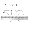
- FIG. 2 shows the transfer state of a magnetic transferring method according to another embodiment of the invention.
- FIG. 2 is a schematic drawing, showing thicknesses, and so on, in ratios different from actual dimensions.
- the magnetic recording plane of the slave medium 2 is brought into close contact with the information bearing plane of the master medium 3 through a liquid layer 4 having a uniform thickness of 100 nm or less, and pressed by a predetermined pressure.
- information such as a servo signal or the like is magnetically transferred and recorded by applying a transfer magnetic field by use of the magnetic field generator 5.
- the liquid layer 4 is preferably formed in a manner that immediately before the slave medium 2 is brought into close contact with the master medium 3, a predetermined amount of liquid is coated uniformly on the information bearing plane of the master medium 3 or the recording plane of the slave medium 2 by dip coating, spin coating, bar coating or the like, both are closely contacted to each other and pressed by a predetermined pressure, and the liquid is laid to have a thickness uniform on a full surface.
- a meniscus force by the liquid present on the close contact surface works to increase a close contact force between the slave medium 2 and the master medium 3.
- a good close contact characteristic can be provided without applying any excessive pressing force.
- a thickness of the liquid layer 4, i.e., a close contact distance between the recording plane of the slave medium 2 and the information bearing plane of the master medium 3, should be set equal to 100 nm or less, preferably in the range of 2 to 50 nm.
- Liquid having a viscosity characteristic providing such a thickness is selected.
- liquid having lubricity is preferred, and lubricant or other additives may be mixed in a solvent thereof.
- an organic solvent containing stearic acid is available as liquid having lubricity.
- hydrocarbon lubricants include carbonic acids such as stearic acid and oleic acid, esters such as stearic butyl, sulfonic acids such as octadecylsufonic acid, ester phosphates such as monooctadecyl phosphate, alcohols such as stearyl alcohol and oleyl alcohol, carbonic amides such as stearine amide, and amines such as stearyl amine.
- carbonic acids such as stearic acid and oleic acid
- esters such as stearic butyl
- sulfonic acids such as octadecylsufonic acid
- ester phosphates such as monooctadecyl phosphate
- alcohols such as stearyl alcohol and oleyl alcohol
- carbonic amides such as stearine amide
- amines such as stearyl amine.
- fluorocarbon lubricants include the aforementioned hydrocarbon compounds with some or all of their alkyl groups replaced by fluoroalkyl groups or perfluoropolyether groups.
- perfluoropolyether groups include perfluoromethylene oxide polymers, perfluoroethylene oxide polymers, perfluoro-n-propylene oxide polymers (CF2CF2CF20)n, perfluoroisopropylene oxide polymers (CF(CF3)CF20)n or copolymers of the above.
- extreme pressure additives include phosphate esters such as trilauryl phosphate, phosphite esters such as trilauryl phosphite, thiophosphite esters such as trilauryl trithiophosphite, thiophosphate esters, and sulfur extreme pressure solutions such as disulfide dibenzyl.
- phosphate esters such as trilauryl phosphate
- phosphite esters such as trilauryl phosphite
- thiophosphite esters such as trilauryl trithiophosphite
- sulfur extreme pressure solutions such as disulfide dibenzyl.
- the lubricants described above are used either singly or in combination.
- the lubricant(s) should be dissolved in an organic solution, then coated thereon by a wire bar method, a gravure method, a spin coat method, or a dip coat method.
- the lubricant may be coated on said layers by a vacuum evaporation method. It is preferable that the amount of lubricant to be coated on the magnetic layer or the protective layer is 1 ⁇ 30mg/m 2 , and more preferably, 2 ⁇ 20mg/m 2 .
- the slave medium 2 and the master medium 3 have been adhered to each other by a large close contact force. Simple peeling-off may cause damage to the slave medium 2 or the master medium 3.
- the slave medium 2 is separated from the master medium 3 while being rotated in parallel to the master medium 3 or moved to be linearly shifted from the master medium 3 so as to be peeled off, and then the close contact therebetween is released. Therefore, the slave medium 2 can be separated from the maser carrier 3 by a small force. As a result, it is possible to enhance workability, prevent the damage of the slave medium 2, and prolong the life of the master medium 3.
- the liquid stuck to the recording plane of the slave medium 2 after the magnetic transfer is removed.
- the liquid In the case of the liquid having lubricity, the liquid is not removed, but rather used continuously. If the liquid has lubricity, since lubricity is provided to the recording plane of the slave medium 2, a lubricant coating step is made unnecessary in the manufacturing process of the slave medium 2, contributing to the simplification of the process.
- the liquid layer 4 interposed between the close contact surfaces of the slave medium 2 and the master medium 3 includes dust stuck to the slave medium 2 or the master medium 3.
- dust of a size equal to or smaller than the thickness of the layer 4 is present within the layer 4, not affecting the close contact distance, and a close contact distance uniform over the full surface is obtained.
- the close contact distance is large in a portion of the stuck dust. In the other portions, the close contact distance is equal to the thickness of the layer 4.
- the slave medium 2 should preferably be a hard disk having magnetic recording layers formed on both surfaces. Before being brought into close contact with the master medium 3, the slave medium 2 is subjected to cleaning, when necessary, to remove very small projections or stuck dust on the surface by a glide head, a polisher or the like.
- the present invention can be applied to magnetic transfer carried out for a flexible disk, especially one having a metallic thin-film magnetic recording layer.
- the master medium 3 is formed in a disk shape. In one surface thereof, a transfer information bearing plane is provided by a micro uneven pattern (described later by referring to FIG. 2). A plane opposite to the transfer information bearing plane is held by an adhering unit (not-shown), and then brought into close contact with the conveyed slave medium 2.
- the master medium 3 is subjected to cleaning, when necessary, to remove dust adhered thereon, before the close contact with the slave medium 2.
- the magnetic field generator 5 for applying a transfer magnetic field is constructed in a manner that an electromagnet device for generating lines of magnetic force parallel to a tracking direction (a direction tangential to a circumferential track) or a permanent magnet device for generating similar lines of magnetic force is disposed in one side or both sides.
- the electromagnet device includes a coil 53 (not shown in FIG. 2) wound on a core 52, which has a gap 51 extended in the radial direction of the master medium 3 held by the adhering unit.
- a transfer magnetic field is applied by the magnetic field generator 5 while rotating the slave medium 2 and the master medium 3 in a united manner, and the transfer information of the master medium 3 is magnetically transferred and recorded on the recording plane of the slave medium 2.
- the magnetic field generator 5 may be provided so as to be rotationally moved.
- FIG. 3A shows the step of subjecting the slave medium 2 to initial DC magnetization by applying a magnetic field in one direction
- FIG. 3B the step of bringing the master medium 3 and the slave medium 2 into close contact with each other and applying a magnetic field in an opposite direction
- FIG. 3C a state after the magnetic transfer.
- the above-described liquid layer 4 is not shown in this case.
- the slave medium 2 is subjected to initial magnetization (DC demagnetization) beforehand by applying an initial magnetic field Hin in one track direction.
- initial magnetization DC demagnetization
- FIG. 3B the magnetic transfer plane of the slave medium 2 is brought into close contact with the information bearing plane of the master medium 3, which is formed by covering the micro uneven pattern of a substrate 31 with a magnetic layer 32, and magnetic transfer is carried out by applying a transfer magnetic field Hdu in a direction opposite to that of the initial magnetic field Hin in the track direction of the slave medium 2.
- FIG. 3C information in accordance with the pattern formed by the close contact projection and the recess space of the magnetic layer 32 of the information bearing plane of the master medium 3 is magnetically transferred and recorded on the magnetic recording plane (track) of the slave medium 2.
- the magnetic transfer can be carried out by use of the substrate 31 only, and it is not necessary to cover the substrate 31 with the magnetic layer 32 (soft magnetic layer). However, better magnetic transfer can be carried out by providing the magnetic layer 32 having a good transfer characteristic.
- the substrate 31 is made of a nonmagnetic material, it is necessary to provide the magnetic layer 32.
- a nonmagnetic layer should be provided between the substrate 31 and the magnetic layer 32 in order to shield influence of magnetism of the substrate 31.
- a protective film made of diamond-like carbon (DLC) or the like is formed on the uppermost layer. By this protective film, resistance to contact can be improved, and the magnetic transfer can be carried out many times.
- a Si film may be formed under the DLC protective film by sputtering or the like.
- the master medium 3 will be described.
- the substrate 31 of the master medium 3 one is selected for use from nickel, silicon, quartz plate, glass, aluminum, an alloy, ceramic, a synthetic resin and the like.
- the formation of the uneven pattern is carried out by a stamper method, a photofabrication method or the like.
- a photoresist is formed on a glass plate (or quartz plate) having a smooth surface by spin coating or the like.
- a laser beam (or electron beam) modulated corresponding to a servo signal is radiated onto the photoresist while this glass plate is rotated.
- a predetermined pattern is formed by exposure on the full surface of the photoresist. For example, the pattern extending linearly from a rotational center in the radial direction in each track and corresponding to a servo signal is formed by exposure in the portion corresponding to each frame on a circumference of the glass plate.
- the photoresist is subjected to development processing, the exposed portions are removed, and an original disk having an uneven pattern by the photoresist is obtained. Then, in accordance with the uneven pattern of the surface of the original disk, this surface is plated (electroforming), a Ni substrate having a positive uneven pattern is formed, and peeled off from the original disk.
- This substrate is used directly as a master medium, or covered with a nonmagnetic layer, a soft magnetic layer and a protective layer when necessary to be used as a master medium.
- the original disk may be plated to prepare a second original disk.
- a substrate having a negative uneven pattern may be formed.
- a third original disk may be prepared by plating the second original disk or pressing resin liquid to the second original disk to carry out hardening. By plating the third original disk, a substrate having a positive uneven pattern may be formed.
- a hole may be formed in the glass plate by etching, and an original disk may be obtained by removing the photoresist.
- a substrate may be formed.
- a depth (projection height) of the uneven pattern of the substrate should preferably be set in the range of 80 nm to 800 nm, more preferably in the range of 150 nm to 600 nm.
- this uneven pattern is formed to be long in a radial direction.
- a length in a radial direction should preferably set in the range of 0,2 to 20 ⁇ m; and that in a circumferential direction in the range of 0.1 to 5 ⁇ m. The selection of a pattern having a longer length in the radial direction than that in the circumferential direction within such a range is preferable for bearing the information of a servo signal.
- the formation of the magnetic layer 32 is carried out by using a plating method, a vacuum film growth means such as a vacuum evaporation method, a sputtering method and an ion plating method or the like to deposit a magnetic material.
- a material for the magnetic layer one can be selected for use from Co, a Co alloy (CoNi, CoNiZr, CoNbTaZr or the like), Fe, and Fe alloy (FeCo, FeCoNi, FeNiMo, FeAlSi, FeAl, FeTaN), Ni, and a Ni alloy (NiFe).
- FeCo and FeCoNi are particularly preferable.
- a thickness of the magnetic layer should preferably be set in the range of 50 nm to 500 nm, more preferably in the range of 100 nm to 400 nm.
- a material for the nonmagnetic layer provided as a base layer under the magnetic layer one can be selected for use from Cr, CrTi, CoCr, CrTa, CrMo, NiAl, Ru, C, Ti, Al, Mo, W, Ta, Nb, and so on. This nonmagnetic layer can suppress a reduction in a signal quality when the substrate is made of a ferromagnetic material.
- a protective film made of DLC or the like should be provided on the magnetic layer, and a lubricant layer may also be provided. It is more preferred that a DLC film and a lubricant film which have a thickness of 5 to 30 nm in total are provided as the protective film.
- a close contact strengthening layer made of Si or the like may be provided between the magnetic layer and the protective film. Lubricant lessens the deterioration in durability caused by damage given by friction when slippage of the master medium caused during the contact process with the slave medium is corrected.
- a resin substrate may be manufactured by using the above-described original disk, and used as a master medium by providing a magnetic layer on the surface thereof.
- a resin material for the resin substrate one can be selected for use from an acrylic resin such as polycarbonate-polymethylmethacrylate, a vinyl chloride resin such as poly vinyl chloride-vinyl chloride copolymer, an epoxy resin, amorphous polyolefin, polyester, and the like. Polycarbonate is preferred considering humidity resistance, dimension stability, costs, and so on. If there are burrs in a molded component, the burrs are removed by burnishing or polishing.
- an ultraviolet curing resin, an electron beam curing resin or the like the substrate may be formed by means of spin coating or bar coating.
- a height of the pattern projection of the resin substrate should preferably be set in the range of 50 to 1000 nm, more preferably in the range of 200 to 500 nm.
- the master medium is obtained by covering the micropattern of the surface of the resin substrate with a magnetic layer.
- the formation of the magnetic layer is carried out by using a plating method, a vacuum film growth means such as a vacuum evaporation method, a sputtering method, an ion plating method or the like to deposit a magnetic material.
- a photoresist is coated on the smooth surface of the flat-plate substrate and a pattern in accordance with the information is formed by exposure and development processing by use of a photomask in accordance with the pattern of a servo signal. Then, in an etching step, the substrate is subjected to etching in accordance with the pattern, and holes of depths equivalent to the thickness of the magnetic layer are formed. Then, a magnetic material is grown up to the surface of the substrate so as to have a thickness corresponding to the hole by a plating method or a vacuum film growth means such as a vacuum evaporation method, a sputtering method, or an ion plating method to deposit a magnetic material. Then, the photoresist is removed by a lift-off method, and the surface of the substrate is polished. If there are burrs, the burrs are removed, and the surface is made smooth.
- the slave medium 2 a coating type magnetic recording medium or a metallic thin-film magnetic recording medium is used.
- a coating type magnetic recoding medium a commercially available medium such as a high-density flexible disk or the like can be used.
- the metallic thin-film magnetic recording medium first for a magnetic material, one can be selected for use from Co, a Co alloy (CoPtCr, CoCr, CoPtCrTa, CoPtCrNbTa, CoCrB, CoNi or the like), Fe, and an Fe alloy (FeCo, FePt, FeCoNi).
- a nonmagnetic base layer should preferably be provided in order to set necessary magnetic anisotropy under the magnetic material (support side).
- the nonmagnetic base layer needs to coincide with the magnetic layer in a crystal structure and a lattice constant.
- FIG. 4 schematically shows a mechanism of a cleaning apparatus.
- a cleaning apparatus 10 shown in FIG. 4 includes: a decompression vessel 13 (vacuum chamber) for housing a master medium 12; a pressure reducing unit 14 for reducing a pressure in the vessel 13; a discharge unit 15 for generating a plasma discharge between a electrode 24 in the vessel 13 and the master medium 12; and a gas introduction unit 16 for introducing reactive gas into the vessel 13.
- a decompression vessel 13 vacuum chamber
- a pressure reducing unit 14 for reducing a pressure in the vessel 13
- a discharge unit 15 for generating a plasma discharge between a electrode 24 in the vessel 13 and the master medium 12
- a gas introduction unit 16 for introducing reactive gas into the vessel 13.
- a cleaning method using the apparatus 10 is designed to remove articles stuck to the surface of the master medium 12 before the magnetic transfer in a non-contact manner in a dry process utilizing reactive plasma etching.
- reactive gas is introduced into the vessel 13 to generate a discharge, and the articles stuck to the surface of the master medium 12 are burned and removed by a plasma discharge.
- the decompression vessel 13 has a cap-shaped cover member 18 placed over a base member 17 to hermetically seal the internal space.
- the base member 17 and the cover member 18 are moved relatively into contact with/away from each other to open/close the internal space, and the master medium 12 is housed inside so as to be replaced by another.
- the master medium 12 is placed on the base member 17. This master medium 12 is set in electrical continuity with the electrically grounded base member 17 to become one pole during discharge, to be described below.
- the pressure reducing unit 14 includes a vacuum pump 20.
- a pressure reduction passage 21 from the vacuum pump 20 is connected to the cover member 18 and, the pressure is reduced to a predetermined level by sucking the inside air of the vessel 13.
- a first valve V1 is disposed in the reduced pressure passage 21. This valve V1 is controlled to be opened during pressure reduction and closed during pressure reduction releasing.
- the pressure reduction passage 21 is provided with a leak passage 22 joining the vessel 13 side of the first valve V1.
- This leak passage 22 is communicated with a leak port, and provided with a second valve V2 disposed midway thereto.
- the second valve V2 is controlled to be closed during pressure reduction and to be opened when the pressure reduction is finished in order to leak to the atmosphere.
- the discharge unit 15 includes a power source 23 (DC power source) for generating a discharge voltage and the plate-shaped discharge electrode 24 disposed inside the cover member 18.
- This discharge electrode 24 is held by a supporting member 25 penetrating the cover member 18 and connected to the power source 23 by an electric conducting member (not shown) disposed inside the supporting member 25.
- An insulating seal 19 is provided between the supporting member 25 and the cover member 18, and the cover member 18 is in an electrically insulated state.
- the discharge electrode 24 is placed opposite to the master medium 12 placed on the base member 17.
- a discharge voltage generated by the power source 23 is applied between the discharge electrode 24 and the master medium 12 to generate a plasma discharge in the master medium 12.
- an RF power source may be used as described later.
- the gas introduction unit 16 includes a gas tank (not shown) for storing reactive gas.
- a gas introduction passage 26 from the gas tank is connected to the cover member 18, and the predetermined amount of reactive gas having high reactivity is introduced into the vessel 13.
- a third valve V3 is disposed in the gas introduction passage 26 and controlled to be opened during gas introduction.
- the reactive gas has a composition containing, for example Ar, O 2 , CCl 4 , and the like.
- the decompression vessel 13 is opened by moving the base member 17 or the cover member 18, and the master medium 12 is placed in a predetermined position on the base member 17 with the information bearing plane up, the information bearing plane having a micro uneven pattern formed by a magnetic material.
- the decompression vessel 13 is set in a hermetically sealed state by moving the base member 17 or the cover member 18.
- the first valve V1 is opened while the second valve V2 is closed.
- Then, by driving the vacuum pump 20, air inside the vessel 13 is sucked to reduce an inner pressure to a predetermined level.
- the third valve V3 is opened to introduce reactive gas through the gas introduction passage 26 into the vessel 13.
- a discharge voltage is applied between the discharge electrode 24 and the master medium 12 by the power source 23 (DC power source), and a plasma discharge is generated in the master medium 12.
- the plasma discharge of the reactive gas the articles stuck to the surface of the master medium 12 are burned and removed by plasma etching.
- the second valve V2 is opened to leak to the atmosphere. Air is introduced through the leak passage 22 to increase the pressure inside the vessel 13 to an atmospheric pressure. Then, the decompression vessel 13 is opened by moving the base member 17 or the cover member 18, and the master medium 12 on the base member 17 is taken out. A next master medium 12 is loaded, and a cleaning process similar to the above is performed thereafter.
- the master medium 12 is conveyed to the magnetic transfer device.
- the information bearing plane of the master medium 12 and the recording plane of the slave medium subjected to initial magnetization in a track direction beforehand are brought into close contact with each other.
- a transfer magnetic field is applied in a direction substantially opposite to that of the initial magnetization by a magnetic field application device such as an electromagnet, and a magnetization pattern corresponding to transfer information of the master medium 12 is transferred and recorded in the slave medium.
- the cleaning of the master medium 12 should be performed in linkage with the magnetic transfer.
- the master medium 12 is subjected to the cleaning.
- the cleaning apparatus 10 is incorporated in a part of the magnetic transfer device. The master medium 12 is taken out from the magnetic transfer part in linkage with the magnetic transfer operation, and conveyed to the cleaning apparatus 10 to be cleaned.
- the master medium is formed by covering the micro uneven pattern of the substrate with the magnetic layer (metallic thin film). If the substrate is made of a ferromagnetic material such as Ni, the magnetic transfer can be carried out by the substrate only, and it is not necessary to cover the substrate with the magnetic layer (soft magnetic layer). However, better magnetic transfer can be carried out by providing the magnetic layer having a good transfer characteristic. If the substrate is made of a nonmagnetic material, it is necessary to provide the magnetic layer. In order to ground the information bearing plane and to generate a discharge along the information bearing plane by the DC power source 23 when the master medium 12 is loaded on the base member 17, preferably, the substrate of the master medium 12 should be made of a conductive material. Alternatively, if the substrate of the master medium 12 is made of an insulating material, preferably, a magnetic layer should be formed on the uneven pattern after a conductive layer is laminated on the substrate.
- the substrate of the master medium 12 is made of an insulating material, preferably, a magnetic layer should be formed on the uneven pattern after
- an RF power source may be used in place of the DC power source.
- the cleaning can be carried out, which is designed to generate a plasma discharge on the surface of the master medium 12, and burn and remove the articles adhered thereon.
- cleaning is performed in a non-contact manner in a dry process by the cleaning apparatus 10, which uses plasma etching by a plasma discharge under the atmosphere of pressure-reduced reactive gas, and then burns and removes the articles stuck to the surface.
- the cleaning apparatus 10 which uses plasma etching by a plasma discharge under the atmosphere of pressure-reduced reactive gas, and then burns and removes the articles stuck to the surface.
Abstract
Description
- The present invention relates to a magnetic transferring method for performing magnetic transfer from a master medium bearing information to a slave medium.
- The magnetic transferring method is designed to transfer a magnetic pattern corresponding to information (e.g., servo signal) borne by a master medium by applying a transfer magnetic field while the master medium bearing transfer information by the micro uneven pattern of a magnetic material and a slave medium subjected to the transfer are kept in a state of close contact. As such magnetic transferring methods, for example, there are those disclosed in Japanese Unexamined Patent Publication Nos. 63(1988)-183623, 10(1998)-40544, 10(1998)-269566, and others.
- In a hard disk, a high recording density flexible disk or the like that is used as the slave medium, the surface of a magnetic recording layer has a lubricating layer formed in order to reduce friction generated by contact with a magnetic head during use.
- However, during the magnetic transfer by the above-described magnetic transferring method, a problem sometimes occurs if the lubricating layer like that described above is formed on the recording plane of the slave medium. Specifically, it may be difficult to peel off the slave medium from the master medium after the magnetic transfer is performed in close contact with the master medium. In addition, dust stuck to the master medium may be adhered to the slave medium after the close contact, causing the increase of an error rate during recording and reproducing in actual use.
- Analysis of the slave medium after the magnetic transfer revealed that the meniscus of the lubricating layer formed on the recording plane brought about an increase in a close contact force between the slave medium and the master medium. It was also discovered that the dust stuck to the master medium was adsorbed on the lubricating layer. Such a phenomenon was particularly conspicuous in slave mediums including a metallic thin-film magnetic recording layer.
- The high close contact force between the slave medium and the master medium makes it difficult to separate the slave medium from the master medium after the magnetic transfer. Forcible peeling-off may damage the slave medium or the master medium. If there is dust adsorbed on the lubricating layer of the slave medium during the magnetic transfer, it is difficult to remove the dust in post-treatment because of strong adhesion force. Following the high-speed rotation of the slave medium, the dust may collide with the magnetic head to cause head crashing or dropout. Consequently, an error occurrence rate may be increased.
- The present invention was made in view of the foregoing problems, and it is an object of the invention to provide a magnetic transferring method designed to facilitate the separation of the slave medium from the master medium after the magnetic transfer and prevent the adsorption of dust on the slave medium.
- During the magnetic transfer by the above-described magnetic transferring method, the close contact state between the slave medium and the master medium affects signal quality after the magnetic transfer. Ideally, a distance between the recording plane of the slave medium and the information bearing plane of the master medium should be set to be less than or equal to 100 nm, and the close contact is required to be in a uniform state on the full surfaces thereof.
- However, dust may be present between the master medium and the slave medium, and space may be formed between the master medium and the slave medium in the vicinity of the dust depending on the size of the dust, making it impossible to realize a close contact state with a uniform distance across the full surfaces. Thus, a difference is generated in the transferred magnetic signals in accordance with the above-described distance, reducing signal quality, and generating an intensity distribution in a read out reproducing output. When the recorded signal is a servo signal, the tracking function is not sufficient, reducing reliability. Regarding the dust, it was discovered that the sticking of powder dust or the like generated during the manufacturing process of the slave medium to the surface thereof was a main cause.
- The present invention was made in view of the foregoing problems, and it is an object of the invention to provide a magnetic transferring method designed to improve signal quality by making the close contact distance between the slave medium and the master medium uniform during the magnetic transfer.
- In addition, during the magnetic transfer by the above-described magnetic transferring method, depending on the repeated use of the master medium, the master medium may be contaminated by foreign articles stuck to its surface. The foreign articles stuck to the master medium are mainly dust, fiber flocks, and so on, generated in the surrounding environment.
- If the magnetic transfer is carried out while such articles are stuck to the master medium, close contact cannot be secured between the master medium and the slave medium in an area ranging from the dust stuck portion as a center up to a periphery. Consequently, it is impossible to carry out pattern transfer at a predetermined signal level, reducing transfer quality. When the recorded signal is a servo signal, a tracking function will not be sufficient, causing a reduction in reliability.
- The repeated close contact between the master medium and the slave medium increases the sticking force of the above-described articles stuck to the surface of the master medium, and equal or more pattern transfer failures occur in all the slave media subjected to the magnetic transfer thereafter. Consequently, many defective products are produced. Further, such stuck articles may deform the surface of the master medium, leading to the loss of its normal function.
- To remove the articles stuck to the master medium, the master medium before the magnetic transfer may be subjected to cleaning carried out by ultrasonic washing using a cleaning solution, wiping or the like. However, by such a method, the removed articles may be adhered again to the master medium after washing, therefore providing insufficient removal and generating a water mark on the surface of the master medium when the cleaning solution is dried or rubbing damage by a wiping material. Consequently, signal transfer failures, or master medium damage may occur. In other words, even if the stuck articles are temporarily removed by the cleaning solution or the wiping material, the articles may be adhered again from the cleaning solution remaining on the surface of the master medium or the wiping material. Especially, there are some fine grains which cannot be removed.
- The present invention was made in view of the foregoing problems, and objects of the invention are to provide a method and an apparatus for cleaning a master medium for magnetic transfer capable of performing high quality magnetic transfer, by removing articles stuck to the master medium in a dry process and in a non-contact manner without any re-adhesion thereof.
- In accordance with the present invention, a magnetic transferring method is provided, comprising the steps of: bringing a master medium and a slave medium into close contact with each other, the master medium bearing information signals, and the slave medium having a lubricating layer formed on a surface of a recording plane during use; applying a transfer magnetic field; and performing magnetic transfer. In this case, the magnetic transfer is performed by bringing the slave medium and the master medium into close contact before formation of the lubricating layer on the slave medium.
- The lubricating layer is formed on the recording plane of the slave medium after the magnetic transfer, thereby reducing friction with a magnetic head during use.
- In accordance with the present invention, a magnetic transferring method is provided, comprising the steps of: bringing a master medium and a slave medium into close contact with each other, the master medium bearing information signals; applying a transfer magnetic field; and performing magnetic transfer. In this case, preferably, a recording plane of the slave medium and an information bearing plane of the master medium are brought into close contact via a liquid.
- Preferably, the liquid has lubricity. This liquid may be coated on the information bearing plane of the master medium. However, preferably, the liquid having lubricity is coated on the recording plane of the slave medium. The coating of the liquid is preferably carried out immediately before close contact for the purpose of reducing the sticking of dust.
- It is preferred that after the magnetic transfer, the close contact between the slave medium and the master medium is released while the slave medium is moved. The liquid stuck to the surface of the slave medium after the magnetic transfer is removed. However, if the liquid has lubricity, the liquid is used without being removed.
- A close contact distance between the recording plane of the slave medium and the information bearing plane of the master medium by the interposition of the liquid is set equal to 100 nm or less, preferably in the range of 2 to 50 nm. Liquid providing such a coating thickness is selected and, when necessary, one having lubricity, or one containing lubricant or other additives is used.
- For the slave medium, before it is brought into close contact with the master medium, cleaning is performed, when necessary, to remove micro projections or dust stuck to the surface. Meanwhile, for the master medium, before it is brought into close contact with the slave medium, cleaning is performed, when necessary, to remove stuck dust.
- There are two magnetic transfer cases. One is a single sided sequential transfer carried out by keeping the master medium in close contact with one plane of the slave medium; and the other a double sided simultaneous transfer carried out by keeping the master media in close contact with both planes of the slave medium. A hard disk is preferred to be used as the slave medium, and a flexible disk can also be used. As a magnetic field generating means for applying a transfer magnetic field, an electromagnet device or a permanent magnet device is employed. While rotating the master medium and the slave medium in relative relation to each other, a transfer magnetic field is applied in a tracking direction from one side or both sides of a close contact portion therebetween.
- As the foregoing magnetic transferring method, one is preferred, which is designed to perform magnetic transfer by first subjecting the slave medium to initial magnetization for DC-magnetizing the same in the track direction, bringing this slave medium and the master medium into close contact, the master medium having a magnetic layer formed on a micro uneven pattern corresponding to transferred information, and then applying a transfer magnetic field in a direction substantially opposite to that of the initial DC magnetization of the slave medium surface. As the information, a servo signal is preferable.
- In accordance with the invention, a method for cleaning a magnetic transfer master medium, used in a magnetic transferring method for magnetically transferring information from the master medium bearing the information to a slave medium is provided, comprising the step of: burning and removing an article stuck to a surface of the master medium before execution of magnetic transfer by using a plasma discharge under an atmosphere of pressure-reduced reactive gas.
- In accordance with the invention, an apparatus for cleaning a magnetic transfer master medium, which is used in a magnetic transferring method for magnetically transferring information from the master medium bearing the information to a slave medium is provided, comprising: a decompression vessel for housing the master medium; a pressure reducing unit for reducing pressure in the vessel; a discharge unit for generating a plasma discharge between an electrode in the vessel and the master medium; and a gas introduction unit for introducing reactive gas into the vessel. In this case, in a pressure reduced state, reactive gas is introduced into the vessel, then a plasma discharge is generated, thereby burning and removing an article stuck to a surface of the master medium.
- For the cleaning of the master medium in accordance with the present invention, a plasma etching technology or the like for removing an oxide film, which is used in the manufacturing process of an integrated circuit, is used. In addition, the cleaning of the master medium is preferably carried out in linkage with the magnetic transfer, and the master medium should preferably be cleaned for each magnetic transfer process or for every predetermined number of magnetic transfer operations. In such a case, it is preferred that a plurality of master media are prepared, and successively cleaned.
- The decompression vessel of the cleaning apparatus is opened/closed to replaceably house the master medium. The pressure reducing unit includes a vacuum pump, and reduces a pressure inside the vessel to a predetermined level. The discharge unit has one pole in electrical continuity with the master medium. Moreover, the discharge unit includes a DC power source or an RF power source for applying a discharge voltage between the master medium and an electrode disposed in the vessel opposite to the pole, and generates a plasma discharge on the master medium. The gas introduction unit introduces the predetermined amount of reactive gas having high reactivity into the vessel.
- According to the present invention, the magnetic transfer is performed by bringing the slave medium before the formation of the lubricating layer on the surface and the master medium into close contact with each other. Thus, it is possible to prevent an increase in a close contact force caused by the meniscus of the lubricating layer and facilitate the peeling-off of the slave medium after the magnetic transfer, thereby enhancing workability. It is also possible to prevent the damage of the slave medium and to prolong the life of the master medium.
- Without adsorbing the dust stuck to the master medium on the lubricating layer of the slave medium during close contact, it is possible to suppress the increase of an error rate, thus enhancing reliability. Particularly with regard to flexible discs, as the possibility of substrate deformation damage caused by contaminant attachment thereto is high, the method of the present invention is effective as a method to prevent an increase in errors of a magnetically transferred signal.
- According to the invention, in the magnetic transfer performed by bringing the master medium having transfer information and the slave medium into close contact with each other and applying a transfer magnetic field, when the recording plane of the slave medium and the information bearing plane of the master medium are brought into close contact with each other through liquid, a close contact distance therebetween becomes a fixed value equivalent to the coating thickness of the liquid on the full surface. As a result, the magnetic transfer can be carried out by a uniform characteristic to increase transfer signal quality, and provide a better intensity distribution of reproducing outputs. A sufficient tracking function can be provided in the case of a servo signal, improving reliability.
- In addition, a meniscus force is applied by the liquid interposed between the close contact surfaces, increasing a close contact force between the slave medium and the master medium. Thus, without applying any excessive pressing forces, it is possible to secure a good contact characteristic.
- If the liquid has lubricity, lubricity is provided to the recording plane of the slave medium. Thus, the lubricant coating step is made unnecessary in the manufacturing process of the slave medium, contributing to the process simplification.
- The close contact force is increased by the interposition of the liquid as described above. However, when the close contact between the slave medium and the master medium is released while the slave medium is moved after the magnetic transfer, the slave medium and the master medium can be separated from each other by a small force, thus enhancing workability. It is also possible to prevent the damage of the slave medium and prolong the life of the master medium.
- Furthermore, according to the invention, the articles stuck to the surface of the master medium are burned and removed by using a plasma discharge under the atmosphere of pressure reduced reactive gas before the magnetic transfer. Thus, stuck articles such as fiber flocks can be removed in non-contact in a dry process. Therefore, as opposed to cleaning by ultrasonic washing, wiping or the like using a washing solution, even fine grains can be removed without re-adhesion of the removed articles to the master medium, or without leaving any water marks or causing rubbing damage. As a result, it is possible to prevent the deterioration of a transfer signal caused by a close contact failure between the master medium and the slave medium, enhance reliability by executing magnetic transfer of a stable quality, and prolong the life of the master medium.
-
- FIG. 1 is a perspective view showing main portions in a magnetic transferring method according to an embodiment of the present invention.
- FIG. 2 is a sectional view showing main portions in the magnetic transferring method according to another embodiment of the present invention.
- FIGS. 3A to 3C are views, each thereof showing a basic step of the magnetic transferring method of the embodiment of the present invention.
- FIG. 4 is a view schematically showing a cleaning apparatus according to yet another embodiment of the present invention.
-
- Next, preferred embodiments of the present invention will be described in detail. FIG. 1 shows a transfer state of a magnetic transferring method according to an embodiment of the present invention. FIG. 1 is a schematic drawing, showing thicknesses and the like in ratios different from actual dimensions.
- In FIG. 1, during magnetic transfer, a magnetic recording plane of a
slave medium 2 having no lubricating layers formed on the surface is brought into contact with an information bearing plane of amaster medium 3, and closely contacted therewith by a predetermined pressing force. In the close contact state of themaster medium 3 and theslave medium 2, information such as a servo signal or the like is magnetically transferred and recorded by applying a transfer magnetic field by use of amagnetic field generator 5. - After the end of the magnetic transfer, the close contact between the
slave medium 2 and themaster medium 3 is released, and theslave medium 2 is separated from themaster medium 3 and unloaded. On the recording plane of theslave medium 2 after the magnetic transfer, a solution containing lubricant is uniformly coated by dip coating, spin coating, bar coating or the like, and dried to form a lubricating layer. - According to the embodiment, during the magnetic transfer, because of no lubricating layers formed on the surface of the
slave medium 2, a close contact force with themaster medium 3 is not increased. Thus, theslave medium 2 can be separated from themaster medium 3 by a small force, making it possible to improve workability, prevent the damage of theslave medium 2, and prolong the life of themaster medium 3. Moreover, dust stuck to themaster medium 3 can be prevented from being adsorbed during the close contact, and dust stuck to the slave medium even after the magnetic transfer can be reduced and removed in the post-treatment. Thus, no increases occur in an error rate, and reliability can be enhanced. - Now, another embodiment of the invention will be described in detail. FIG. 2 shows the transfer state of a magnetic transferring method according to another embodiment of the invention. FIG. 2 is a schematic drawing, showing thicknesses, and so on, in ratios different from actual dimensions.
- In FIG. 2, during the magnetic transfer, the magnetic recording plane of the
slave medium 2 is brought into close contact with the information bearing plane of themaster medium 3 through aliquid layer 4 having a uniform thickness of 100 nm or less, and pressed by a predetermined pressure. In the close contact state of themaster medium 3 and theslave medium 2, information such as a servo signal or the like is magnetically transferred and recorded by applying a transfer magnetic field by use of themagnetic field generator 5. - The
liquid layer 4 is preferably formed in a manner that immediately before theslave medium 2 is brought into close contact with themaster medium 3, a predetermined amount of liquid is coated uniformly on the information bearing plane of themaster medium 3 or the recording plane of theslave medium 2 by dip coating, spin coating, bar coating or the like, both are closely contacted to each other and pressed by a predetermined pressure, and the liquid is laid to have a thickness uniform on a full surface. In the close contact state, a meniscus force by the liquid present on the close contact surface works to increase a close contact force between theslave medium 2 and themaster medium 3. Thus, a good close contact characteristic can be provided without applying any excessive pressing force. - A thickness of the
liquid layer 4, i.e., a close contact distance between the recording plane of theslave medium 2 and the information bearing plane of themaster medium 3, should be set equal to 100 nm or less, preferably in the range of 2 to 50 nm. Liquid having a viscosity characteristic providing such a thickness is selected. Especially, liquid having lubricity is preferred, and lubricant or other additives may be mixed in a solvent thereof. For example, as liquid having lubricity, an organic solvent containing stearic acid is available. - Known substances such as hydrocarbon lubricants, fluorocarbon lubricants, and extreme pressure additives may be used as the lubricant. Examples of hydrocarbon lubricants include carbonic acids such as stearic acid and oleic acid, esters such as stearic butyl, sulfonic acids such as octadecylsufonic acid, ester phosphates such as monooctadecyl phosphate, alcohols such as stearyl alcohol and oleyl alcohol, carbonic amides such as stearine amide, and amines such as stearyl amine.
- Examples of fluorocarbon lubricants include the aforementioned hydrocarbon compounds with some or all of their alkyl groups replaced by fluoroalkyl groups or perfluoropolyether groups. Examples of perfluoropolyether groups include perfluoromethylene oxide polymers, perfluoroethylene oxide polymers, perfluoro-n-propylene oxide polymers (CF2CF2CF20)n, perfluoroisopropylene oxide polymers (CF(CF3)CF20)n or copolymers of the above.
- Examples of extreme pressure additives include phosphate esters such as trilauryl phosphate, phosphite esters such as trilauryl phosphite, thiophosphite esters such as trilauryl trithiophosphite, thiophosphate esters, and sulfur extreme pressure solutions such as disulfide dibenzyl.
- The lubricants described above are used either singly or in combination. In order to provide said lubricant(s) to the magnetic layer or the protective layer, the lubricant(s) should be dissolved in an organic solution, then coated thereon by a wire bar method, a gravure method, a spin coat method, or a dip coat method. Alternatively, the lubricant may be coated on said layers by a vacuum evaporation method. It is preferable that the amount of lubricant to be coated on the magnetic layer or the protective layer is 1 ∼ 30mg/m2, and more preferably, 2 ∼ 20mg/m2.
- After the completion of the magnetic transfer, because of the interposition of the
liquid layer 4, theslave medium 2 and themaster medium 3 have been adhered to each other by a large close contact force. Simple peeling-off may cause damage to theslave medium 2 or themaster medium 3. Thus, after the magnetic transfer, theslave medium 2 is separated from themaster medium 3 while being rotated in parallel to themaster medium 3 or moved to be linearly shifted from themaster medium 3 so as to be peeled off, and then the close contact therebetween is released. Therefore, theslave medium 2 can be separated from themaser carrier 3 by a small force. As a result, it is possible to enhance workability, prevent the damage of theslave medium 2, and prolong the life of themaster medium 3. - The liquid stuck to the recording plane of the
slave medium 2 after the magnetic transfer is removed. In the case of the liquid having lubricity, the liquid is not removed, but rather used continuously. If the liquid has lubricity, since lubricity is provided to the recording plane of theslave medium 2, a lubricant coating step is made unnecessary in the manufacturing process of theslave medium 2, contributing to the simplification of the process. - According to the foregoing embodiment, the
liquid layer 4 interposed between the close contact surfaces of theslave medium 2 and themaster medium 3 includes dust stuck to theslave medium 2 or themaster medium 3. However, dust of a size equal to or smaller than the thickness of thelayer 4 is present within thelayer 4, not affecting the close contact distance, and a close contact distance uniform over the full surface is obtained. If there is dust of a size larger than the thickness of thelayer 4, the close contact distance is large in a portion of the stuck dust. In the other portions, the close contact distance is equal to the thickness of thelayer 4. Thus, compared with a contact distance in the state of no liquid, variation in the close contact distance on the full surface is reduced, a difference in transfer characteristics is smaller during transfer, and a difference in the reproducing outputs of the transfer signals is reduced. - In each of FIGS. 1 and 2, the
slave medium 2 should preferably be a hard disk having magnetic recording layers formed on both surfaces. Before being brought into close contact with themaster medium 3, theslave medium 2 is subjected to cleaning, when necessary, to remove very small projections or stuck dust on the surface by a glide head, a polisher or the like. The present invention can be applied to magnetic transfer carried out for a flexible disk, especially one having a metallic thin-film magnetic recording layer. - The
master medium 3 is formed in a disk shape. In one surface thereof, a transfer information bearing plane is provided by a micro uneven pattern (described later by referring to FIG. 2). A plane opposite to the transfer information bearing plane is held by an adhering unit (not-shown), and then brought into close contact with the conveyedslave medium 2. There are two transfer operation cases. One is a one-sided sequential transfer carried out by keeping themaster medium 3 in close contact with one plane of the slave medium; and the other is a double-sided simultaneous transfer carried out by keeping themaster media 3 in close contact with both planes of the slave medium. Themaster medium 3 is subjected to cleaning, when necessary, to remove dust adhered thereon, before the close contact with theslave medium 2. - The
magnetic field generator 5 for applying a transfer magnetic field is constructed in a manner that an electromagnet device for generating lines of magnetic force parallel to a tracking direction (a direction tangential to a circumferential track) or a permanent magnet device for generating similar lines of magnetic force is disposed in one side or both sides. The electromagnet device includes a coil 53 (not shown in FIG. 2) wound on acore 52, which has agap 51 extended in the radial direction of themaster medium 3 held by the adhering unit. During magnetic field application, a transfer magnetic field is applied by themagnetic field generator 5 while rotating theslave medium 2 and themaster medium 3 in a united manner, and the transfer information of themaster medium 3 is magnetically transferred and recorded on the recording plane of theslave medium 2. Themagnetic field generator 5 may be provided so as to be rotationally moved. - Next, description will be made by referring to FIGS. 3A to 3C, showing a basic process of the magnetic transfer. Specifically, FIG. 3A shows the step of subjecting the
slave medium 2 to initial DC magnetization by applying a magnetic field in one direction; FIG. 3B the step of bringing themaster medium 3 and theslave medium 2 into close contact with each other and applying a magnetic field in an opposite direction; and FIG. 3C a state after the magnetic transfer. The above-describedliquid layer 4 is not shown in this case. - First, as shown in FIG. 3A, the
slave medium 2 is subjected to initial magnetization (DC demagnetization) beforehand by applying an initial magnetic field Hin in one track direction. Then, as shown in FIG. 3B, the magnetic transfer plane of theslave medium 2 is brought into close contact with the information bearing plane of themaster medium 3, which is formed by covering the micro uneven pattern of asubstrate 31 with amagnetic layer 32, and magnetic transfer is carried out by applying a transfer magnetic field Hdu in a direction opposite to that of the initial magnetic field Hin in the track direction of theslave medium 2. As a result, as shown in FIG. 3C, information in accordance with the pattern formed by the close contact projection and the recess space of themagnetic layer 32 of the information bearing plane of themaster medium 3 is magnetically transferred and recorded on the magnetic recording plane (track) of theslave medium 2. - Even when the uneven pattern of the
substrate 31 of themaster medium 3 is an uneven negative pattern opposite to the positive pattern of FIG. 2, similar information can be magnetically transferred and recorded by reversing the directions of the initial magnetic field Hin and the transfer magnetic field Hdu from the above. - When the
substrate 31 is made of a ferromagnetic material such as Ni, the magnetic transfer can be carried out by use of thesubstrate 31 only, and it is not necessary to cover thesubstrate 31 with the magnetic layer 32 (soft magnetic layer). However, better magnetic transfer can be carried out by providing themagnetic layer 32 having a good transfer characteristic. When thesubstrate 31 is made of a nonmagnetic material, it is necessary to provide themagnetic layer 32. - When the
substrate 31 made of ferromagnetic metal is covered with themagnetic layer 32, preferably, a nonmagnetic layer should be provided between thesubstrate 31 and themagnetic layer 32 in order to shield influence of magnetism of thesubstrate 31. Further, a protective film made of diamond-like carbon (DLC) or the like is formed on the uppermost layer. By this protective film, resistance to contact can be improved, and the magnetic transfer can be carried out many times. A Si film may be formed under the DLC protective film by sputtering or the like. - Now, the
master medium 3 will be described. For thesubstrate 31 of themaster medium 3, one is selected for use from nickel, silicon, quartz plate, glass, aluminum, an alloy, ceramic, a synthetic resin and the like. The formation of the uneven pattern is carried out by a stamper method, a photofabrication method or the like. - According to the stamper method, a photoresist is formed on a glass plate (or quartz plate) having a smooth surface by spin coating or the like. A laser beam (or electron beam) modulated corresponding to a servo signal is radiated onto the photoresist while this glass plate is rotated. Then, a predetermined pattern is formed by exposure on the full surface of the photoresist. For example, the pattern extending linearly from a rotational center in the radial direction in each track and corresponding to a servo signal is formed by exposure in the portion corresponding to each frame on a circumference of the glass plate. Subsequently, the photoresist is subjected to development processing, the exposed portions are removed, and an original disk having an uneven pattern by the photoresist is obtained. Then, in accordance with the uneven pattern of the surface of the original disk, this surface is plated (electroforming), a Ni substrate having a positive uneven pattern is formed, and peeled off from the original disk. This substrate is used directly as a master medium, or covered with a nonmagnetic layer, a soft magnetic layer and a protective layer when necessary to be used as a master medium.
- The original disk may be plated to prepare a second original disk. By using this second original disk to carry out plating, a substrate having a negative uneven pattern may be formed. Further, a third original disk may be prepared by plating the second original disk or pressing resin liquid to the second original disk to carry out hardening. By plating the third original disk, a substrate having a positive uneven pattern may be formed.
- On the other hand, after a pattern is formed by the photoresist on the glass plate, a hole may be formed in the glass plate by etching, and an original disk may be obtained by removing the photoresist. By a process similar to the above thereafter, a substrate may be formed.
- As a material for the metallic substrate, Ni or a Ni alloy can be used and, for the plating carried out to form the substrate, various metal film growth methods including electroless plating, electroforming, sputtering and ion plating can be used. A depth (projection height) of the uneven pattern of the substrate should preferably be set in the range of 80 nm to 800 nm, more preferably in the range of 150 nm to 600 nm. In the case of a servo signal, this uneven pattern is formed to be long in a radial direction. For example, a length in a radial direction should preferably set in the range of 0,2 to 20 µm; and that in a circumferential direction in the range of 0.1 to 5 µm. The selection of a pattern having a longer length in the radial direction than that in the circumferential direction within such a range is preferable for bearing the information of a servo signal.
- The formation of the magnetic layer 32 (soft magnetic layer) is carried out by using a plating method, a vacuum film growth means such as a vacuum evaporation method, a sputtering method and an ion plating method or the like to deposit a magnetic material. As a material for the magnetic layer, one can be selected for use from Co, a Co alloy (CoNi, CoNiZr, CoNbTaZr or the like), Fe, and Fe alloy (FeCo, FeCoNi, FeNiMo, FeAlSi, FeAl, FeTaN), Ni, and a Ni alloy (NiFe). FeCo and FeCoNi are particularly preferable. A thickness of the magnetic layer should preferably be set in the range of 50 nm to 500 nm, more preferably in the range of 100 nm to 400 nm. As a material for the nonmagnetic layer provided as a base layer under the magnetic layer, one can be selected for use from Cr, CrTi, CoCr, CrTa, CrMo, NiAl, Ru, C, Ti, Al, Mo, W, Ta, Nb, and so on. This nonmagnetic layer can suppress a reduction in a signal quality when the substrate is made of a ferromagnetic material.
- Preferably, a protective film made of DLC or the like should be provided on the magnetic layer, and a lubricant layer may also be provided. It is more preferred that a DLC film and a lubricant film which have a thickness of 5 to 30 nm in total are provided as the protective film. In addition, a close contact strengthening layer made of Si or the like may be provided between the magnetic layer and the protective film. Lubricant lessens the deterioration in durability caused by damage given by friction when slippage of the master medium caused during the contact process with the slave medium is corrected.
- A resin substrate may be manufactured by using the above-described original disk, and used as a master medium by providing a magnetic layer on the surface thereof. As a resin material for the resin substrate, one can be selected for use from an acrylic resin such as polycarbonate-polymethylmethacrylate, a vinyl chloride resin such as poly vinyl chloride-vinyl chloride copolymer, an epoxy resin, amorphous polyolefin, polyester, and the like. Polycarbonate is preferred considering humidity resistance, dimension stability, costs, and so on. If there are burrs in a molded component, the burrs are removed by burnishing or polishing. In addition, by using an ultraviolet curing resin, an electron beam curing resin or the like, the substrate may be formed by means of spin coating or bar coating. A height of the pattern projection of the resin substrate should preferably be set in the range of 50 to 1000 nm, more preferably in the range of 200 to 500 nm.
- The master medium is obtained by covering the micropattern of the surface of the resin substrate with a magnetic layer. The formation of the magnetic layer is carried out by using a plating method, a vacuum film growth means such as a vacuum evaporation method, a sputtering method, an ion plating method or the like to deposit a magnetic material.
- On the other hand, in the lithography method, for example, a photoresist is coated on the smooth surface of the flat-plate substrate and a pattern in accordance with the information is formed by exposure and development processing by use of a photomask in accordance with the pattern of a servo signal. Then, in an etching step, the substrate is subjected to etching in accordance with the pattern, and holes of depths equivalent to the thickness of the magnetic layer are formed. Then, a magnetic material is grown up to the surface of the substrate so as to have a thickness corresponding to the hole by a plating method or a vacuum film growth means such as a vacuum evaporation method, a sputtering method, or an ion plating method to deposit a magnetic material. Then, the photoresist is removed by a lift-off method, and the surface of the substrate is polished. If there are burrs, the burrs are removed, and the surface is made smooth.
- Now, the
slave medium 2 will be described. For the slave medium, a coating type magnetic recording medium or a metallic thin-film magnetic recording medium is used. As the coating type magnetic recoding medium, a commercially available medium such as a high-density flexible disk or the like can be used. Regarding the metallic thin-film magnetic recording medium, first for a magnetic material, one can be selected for use from Co, a Co alloy (CoPtCr, CoCr, CoPtCrTa, CoPtCrNbTa, CoCrB, CoNi or the like), Fe, and an Fe alloy (FeCo, FePt, FeCoNi). These magnetic materials have large magnetic flux densities and magnetic anisotropy in a similar direction to the slave medium (the direction is parallel to the surfaces of the master medium and the slave medium in the case of an in-plane recording, and the direction is perpendicular to the surfaces of the master medium and the slave medium in the case of a perpendicular recording), and are thus preferable because a clear transfer can be performed by use of them. A nonmagnetic base layer should preferably be provided in order to set necessary magnetic anisotropy under the magnetic material (support side). The nonmagnetic base layer needs to coincide with the magnetic layer in a crystal structure and a lattice constant. Thus, one is selected for use from Cr, CrTi, CoCr, CrTa, CrMo, NiAl, Ru, and so on. - Next, yet another embodiment of the invention will be described in detail. FIG. 4 schematically shows a mechanism of a cleaning apparatus.
- A
cleaning apparatus 10 shown in FIG. 4 includes: a decompression vessel 13 (vacuum chamber) for housing amaster medium 12; apressure reducing unit 14 for reducing a pressure in thevessel 13; adischarge unit 15 for generating a plasma discharge between aelectrode 24 in thevessel 13 and themaster medium 12; and agas introduction unit 16 for introducing reactive gas into thevessel 13. - A cleaning method using the
apparatus 10 is designed to remove articles stuck to the surface of themaster medium 12 before the magnetic transfer in a non-contact manner in a dry process utilizing reactive plasma etching. In other words, in the pressure reduced state, reactive gas is introduced into thevessel 13 to generate a discharge, and the articles stuck to the surface of themaster medium 12 are burned and removed by a plasma discharge. - The
decompression vessel 13 has a cap-shapedcover member 18 placed over abase member 17 to hermetically seal the internal space. Thebase member 17 and thecover member 18 are moved relatively into contact with/away from each other to open/close the internal space, and themaster medium 12 is housed inside so as to be replaced by another. Themaster medium 12 is placed on thebase member 17. Thismaster medium 12 is set in electrical continuity with the electrically groundedbase member 17 to become one pole during discharge, to be described below. - The
pressure reducing unit 14 includes avacuum pump 20. Apressure reduction passage 21 from thevacuum pump 20 is connected to thecover member 18 and, the pressure is reduced to a predetermined level by sucking the inside air of thevessel 13. A first valve V1 is disposed in the reducedpressure passage 21. This valve V1 is controlled to be opened during pressure reduction and closed during pressure reduction releasing. In addition, thepressure reduction passage 21 is provided with aleak passage 22 joining thevessel 13 side of the first valve V1. Thisleak passage 22 is communicated with a leak port, and provided with a second valve V2 disposed midway thereto. The second valve V2 is controlled to be closed during pressure reduction and to be opened when the pressure reduction is finished in order to leak to the atmosphere. - The
discharge unit 15 includes a power source 23 (DC power source) for generating a discharge voltage and the plate-shapeddischarge electrode 24 disposed inside thecover member 18. Thisdischarge electrode 24 is held by a supportingmember 25 penetrating thecover member 18 and connected to thepower source 23 by an electric conducting member (not shown) disposed inside the supportingmember 25. An insulatingseal 19 is provided between the supportingmember 25 and thecover member 18, and thecover member 18 is in an electrically insulated state. Thedischarge electrode 24 is placed opposite to themaster medium 12 placed on thebase member 17. A discharge voltage generated by thepower source 23 is applied between thedischarge electrode 24 and themaster medium 12 to generate a plasma discharge in themaster medium 12. For thepower source 23, an RF power source may be used as described later. - The
gas introduction unit 16 includes a gas tank (not shown) for storing reactive gas. Agas introduction passage 26 from the gas tank is connected to thecover member 18, and the predetermined amount of reactive gas having high reactivity is introduced into thevessel 13. A third valve V3 is disposed in thegas introduction passage 26 and controlled to be opened during gas introduction. The reactive gas has a composition containing, for example Ar, O2, CCl4, and the like. - Now, the operation of the
cleaning apparatus 10 constructed in the foregoing manner will be described. First, thedecompression vessel 13 is opened by moving thebase member 17 or thecover member 18, and themaster medium 12 is placed in a predetermined position on thebase member 17 with the information bearing plane up, the information bearing plane having a micro uneven pattern formed by a magnetic material. Thedecompression vessel 13 is set in a hermetically sealed state by moving thebase member 17 or thecover member 18. The first valve V1 is opened while the second valve V2 is closed. Then, by driving thevacuum pump 20, air inside thevessel 13 is sucked to reduce an inner pressure to a predetermined level. After the predetermined pressure reduced state has been set, the third valve V3 is opened to introduce reactive gas through thegas introduction passage 26 into thevessel 13. When a predetermined gas composition is set inside thevessel 13, a discharge voltage is applied between thedischarge electrode 24 and themaster medium 12 by the power source 23 (DC power source), and a plasma discharge is generated in themaster medium 12. By the plasma discharge of the reactive gas, the articles stuck to the surface of themaster medium 12 are burned and removed by plasma etching. - After the completion of cleaning carried out for a predetermined time, while the first and third valves V1 and V3 are maintained in closed states, the second valve V2 is opened to leak to the atmosphere. Air is introduced through the
leak passage 22 to increase the pressure inside thevessel 13 to an atmospheric pressure. Then, thedecompression vessel 13 is opened by moving thebase member 17 or thecover member 18, and themaster medium 12 on thebase member 17 is taken out. Anext master medium 12 is loaded, and a cleaning process similar to the above is performed thereafter. - After the cleaning, the
master medium 12 is conveyed to the magnetic transfer device. The information bearing plane of themaster medium 12 and the recording plane of the slave medium subjected to initial magnetization in a track direction beforehand are brought into close contact with each other. In this close contact state, a transfer magnetic field is applied in a direction substantially opposite to that of the initial magnetization by a magnetic field application device such as an electromagnet, and a magnetization pattern corresponding to transfer information of themaster medium 12 is transferred and recorded in the slave medium. - Preferably, the cleaning of the
master medium 12 should be performed in linkage with the magnetic transfer. For each magnetic transfer process or for every predetermined number of magnetic transfer operations, themaster medium 12 is subjected to the cleaning. In this case, it is preferred for efficiency that a plurality ofmaster media 12 are prepared, and successively changed to cleaned ones. Thecleaning apparatus 10 is incorporated in a part of the magnetic transfer device. Themaster medium 12 is taken out from the magnetic transfer part in linkage with the magnetic transfer operation, and conveyed to thecleaning apparatus 10 to be cleaned. - The master medium is formed by covering the micro uneven pattern of the substrate with the magnetic layer (metallic thin film). If the substrate is made of a ferromagnetic material such as Ni, the magnetic transfer can be carried out by the substrate only, and it is not necessary to cover the substrate with the magnetic layer (soft magnetic layer). However, better magnetic transfer can be carried out by providing the magnetic layer having a good transfer characteristic. If the substrate is made of a nonmagnetic material, it is necessary to provide the magnetic layer. In order to ground the information bearing plane and to generate a discharge along the information bearing plane by the
DC power source 23 when themaster medium 12 is loaded on thebase member 17, preferably, the substrate of themaster medium 12 should be made of a conductive material. Alternatively, if the substrate of themaster medium 12 is made of an insulating material, preferably, a magnetic layer should be formed on the uneven pattern after a conductive layer is laminated on the substrate. - Moreover, for the
power source 23 of thedischarge unit 15, an RF power source may be used in place of the DC power source. In such a case, even if themaster medium 12 is insulative, and not grounded to thebase member 17, the cleaning can be carried out, which is designed to generate a plasma discharge on the surface of themaster medium 12, and burn and remove the articles adhered thereon. - According to the foregoing embodiment of the invention, for the
master medium 12 for magnetic transfer before the execution of magnetic transfer in close contact with the slave medium, cleaning is performed in a non-contact manner in a dry process by thecleaning apparatus 10, which uses plasma etching by a plasma discharge under the atmosphere of pressure-reduced reactive gas, and then burns and removes the articles stuck to the surface. Thus, it is possible to perform good cleaning without re-adhesion of any removed articles, or without leaving any water marks or causing rubbing damage on the surface. It is also possible to perform high quality magnetic transfer by enhancing a close contact characteristic with the slave medium during the magnetic transfer. It is further possible to prolong the life of the master medium by preventing the damage of the master medium.
Claims (8)
- A magnetic transferring method comprising the steps of:wherein the magnetic transfer is performed by bringing the slave medium and the master medium into close contact before formation of the lubricating layer.bringing a master medium and a slave medium into close contact with each other, the master medium bearing information signals, and the slave medium including a lubricating layer formed on a surface of a recording plane during use;applying a transfer magnetic field; andperforming magnetic transfer,
- A magnetic transferring method comprising the steps of:wherein a recording plane of the slave medium and an information bearing plane of the master medium are brought into close contact through liquid.bringing a master medium and a slave medium into close contact with each other, the master medium bearing information signals;applying a transfer magnetic field; andperforming magnetic transfer,
- The magnetic transferring method according to claim 2, wherein said liquid has lubricity.
- The magnetic transferring method according to claim 2, wherein said liquid having lubricity is coated on the recording plane of the slave medium.
- The magnetic transferring method according to claim 3, wherein said liquid having lubricity is coated on the recording plane of the slave medium.
- The magnetic transferring method according to any one of claims 2 to 5, wherein after the magnetic transfer, the close contact between the slave medium and the master medium is released while the slave medium is moved.
- A method for cleaning a magnetic transfer master medium, used in a magnetic transferring method for magnetically transferring information from the master medium bearing the information to a slave medium, comprising the step of:burning and removing an article stuck to a surface of the master medium before execution of magnetic transfer by using a plasma discharge under an atmosphere of pressure-reduced reactive gas.
- An apparatus for cleaning a magnetic transfer master medium, used in a magnetic transferring method for magnetically transferring information from the master medium bearing the information to a slave medium, comprising:wherein in a pressure reduced state, reactive gas is introduced into said vessel to generate a discharge, and an article stuck to a surface of the master medium is burned and removed by a plasma discharge.a decompression vessel for housing the master medium;a pressure reducing unit for reducing a pressure in said vessel;a discharge unit for generating a plasma discharge between an electrode in said vessel and the master medium; anda gas introduction unit for introducing reactive gas into said vessel,
Applications Claiming Priority (6)
| Application Number | Priority Date | Filing Date | Title |
|---|---|---|---|
| JP2000361212A JP2002170231A (en) | 2000-11-28 | 2000-11-28 | Magnetic transfer method |
| JP2000360464 | 2000-11-28 | ||
| JP2000360464A JP2002170230A (en) | 2000-11-28 | 2000-11-28 | Magnetic transfer method |
| JP2000361212 | 2000-11-28 | ||
| JP2000378519 | 2000-12-13 | ||
| JP2000378519 | 2000-12-13 |
Publications (2)
| Publication Number | Publication Date |
|---|---|
| EP1209668A2 true EP1209668A2 (en) | 2002-05-29 |
| EP1209668A3 EP1209668A3 (en) | 2007-08-22 |
Family
ID=27345271
Family Applications (1)
| Application Number | Title | Priority Date | Filing Date |
|---|---|---|---|
| EP01127476A Withdrawn EP1209668A3 (en) | 2000-11-28 | 2001-11-28 | Magnetic transferring method, and method and apparatus for cleaning magnetic transfer master medium |
Country Status (6)
| Country | Link |
|---|---|
| US (2) | US6865038B2 (en) |
| EP (1) | EP1209668A3 (en) |
| KR (1) | KR20020041772A (en) |
| CN (1) | CN1238841C (en) |
| MY (1) | MY134099A (en) |
| SG (1) | SG107569A1 (en) |
Cited By (3)
| Publication number | Priority date | Publication date | Assignee | Title |
|---|---|---|---|---|
| EP1258885A2 (en) * | 2001-05-18 | 2002-11-20 | Fuji Photo Film Co., Ltd. | Master medium cleaning method |
| EP1345211A2 (en) * | 2002-03-15 | 2003-09-17 | Fuji Photo Film Co., Ltd. | Holder for magnetic transfer apparatus |
| SG104290A1 (en) * | 2000-12-05 | 2004-06-21 | Matsushita Electric Ind Co Ltd | Magnetic transcription device |
Families Citing this family (5)
| Publication number | Priority date | Publication date | Assignee | Title |
|---|---|---|---|---|
| US20020187295A1 (en) * | 2001-05-15 | 2002-12-12 | Fuji Photo Film Co., Ltd. | Magnetic transfer master medium |
| CN1235198C (en) * | 2001-05-18 | 2006-01-04 | 富士胶片株式会社 | Main carrier for magnetic copying |
| JP4056526B2 (en) * | 2003-04-01 | 2008-03-05 | 富士通株式会社 | Magnetic pattern transfer method |
| JP4191096B2 (en) * | 2003-07-18 | 2008-12-03 | Tdk株式会社 | Method for processing workpiece including magnetic material and method for manufacturing magnetic recording medium |
| JP2005267730A (en) * | 2004-03-18 | 2005-09-29 | Fuji Photo Film Co Ltd | Master carrier for magnetic transfer, magnetic transfer device, and magnetic transfer method |
Citations (1)
| Publication number | Priority date | Publication date | Assignee | Title |
|---|---|---|---|---|
| NL1012035A1 (en) * | 1998-05-14 | 1999-11-16 | Matsushita Electric Ind Co Ltd | Method of forming a metal stamp, metal stamp and production method for substrates of optical discs using the stamp and optical discs manufactured by the production method. |
Family Cites Families (20)
| Publication number | Priority date | Publication date | Assignee | Title |
|---|---|---|---|---|
| GB1416727A (en) * | 1971-12-27 | 1975-12-03 | Ricoh Kk | Magnetic induction apparatus |
| US4633351A (en) * | 1983-08-02 | 1986-12-30 | Harris Graphics Corporation | Method and apparatus for hydrodynamic magnetic recording |
| JPS63183623A (en) | 1987-01-23 | 1988-07-29 | Sony Corp | Method for contact magnetic field transfer to flexible disk |
| US4863809A (en) * | 1988-03-10 | 1989-09-05 | Magnetic Peripherals, Inc. | Surface treatment for sliders and carbon coated magnetic media |
| GB2280983A (en) * | 1993-08-13 | 1995-02-15 | Robert Irving Farrow | A video tape duplicator with endless loop master tape storage and loading |
| AU7682594A (en) * | 1993-09-08 | 1995-03-27 | Uvtech Systems, Inc. | Surface processing |
| US5663127A (en) * | 1994-07-29 | 1997-09-02 | Minnesota Mining And Manufacturing Company | Perfluoropolyether lubricating compositions |
| GB9603295D0 (en) * | 1996-02-16 | 1996-04-17 | Boc Group Plc | Process and apparatus for surface cleaning |
| FR2751128B1 (en) * | 1996-07-09 | 1998-09-11 | Commissariat Energie Atomique | PROCESS FOR CLEANING METAL SURFACES BY PLASMA |
| JP3343326B2 (en) | 1997-03-27 | 2002-11-11 | 松下電器産業株式会社 | Master information carrier |
| TW342495B (en) * | 1996-07-22 | 1998-10-11 | Matsushita Electric Ind Co Ltd | Master information carrier, method of producing the same, and method for recording master information signal on magnetic recording medium |
| JPH1040554A (en) | 1996-07-24 | 1998-02-13 | Nec Corp | Access control system of optical disc apparatus |
| US5991104A (en) * | 1996-11-27 | 1999-11-23 | Seagate Technology, Inc. | Using servowriter medium for quickly written servo-patterns on magnetic media |
| JPH10239923A (en) | 1997-02-28 | 1998-09-11 | Brother Ind Ltd | Image recorder, residual coating material detecting method therefor and storage medium |
| JPH10293923A (en) * | 1997-04-18 | 1998-11-04 | Hitachi Ltd | Burnishing device for magnetic disk device and glide test method |
| JPH1125455A (en) * | 1997-06-30 | 1999-01-29 | Matsushita Electric Ind Co Ltd | Magnetic transfer device |
| JP4099860B2 (en) * | 1997-10-09 | 2008-06-11 | 富士電機デバイステクノロジー株式会社 | Liquid lubricant, magnetic recording medium using the same, and manufacturing method thereof |
| JPH11296849A (en) * | 1998-04-10 | 1999-10-29 | Matsushita Electric Ind Co Ltd | Master information carrier |
| US6433944B1 (en) * | 1998-09-25 | 2002-08-13 | Fuji Photo Film Co., Ltd. | Master carrier for magnetic transfer and method for transfer |
| WO2000065580A1 (en) * | 1999-04-27 | 2000-11-02 | Matsushita Electric Industrial Co., Ltd. | Method of recording on disk-like recording medium |
-
2001
- 2001-11-27 SG SG200107321A patent/SG107569A1/en unknown
- 2001-11-27 KR KR1020010074331A patent/KR20020041772A/en not_active Application Discontinuation
- 2001-11-27 MY MYPI20015414A patent/MY134099A/en unknown
- 2001-11-28 CN CNB011397225A patent/CN1238841C/en not_active Expired - Fee Related
- 2001-11-28 US US09/994,891 patent/US6865038B2/en not_active Expired - Fee Related
- 2001-11-28 EP EP01127476A patent/EP1209668A3/en not_active Withdrawn
-
2002
- 2002-02-08 US US09/994,891 patent/US20020141088A1/en active Granted
Patent Citations (2)
| Publication number | Priority date | Publication date | Assignee | Title |
|---|---|---|---|---|
| NL1012035A1 (en) * | 1998-05-14 | 1999-11-16 | Matsushita Electric Ind Co Ltd | Method of forming a metal stamp, metal stamp and production method for substrates of optical discs using the stamp and optical discs manufactured by the production method. |
| US6352656B1 (en) * | 1998-05-14 | 2002-03-05 | Matsushita Electric Industrial Co., Ltd. | Manufacturing method for metallic stamper and metallic stamper and, manufacturing method for optical disk substrate with the use of the stamper and optical disk fabricated by the manufacturing method |
Cited By (8)
| Publication number | Priority date | Publication date | Assignee | Title |
|---|---|---|---|---|
| SG104290A1 (en) * | 2000-12-05 | 2004-06-21 | Matsushita Electric Ind Co Ltd | Magnetic transcription device |
| US6785070B2 (en) | 2000-12-05 | 2004-08-31 | Matsushita Electric Industrial Co., Ltd. | Magnetic transcription device |
| EP1258885A2 (en) * | 2001-05-18 | 2002-11-20 | Fuji Photo Film Co., Ltd. | Master medium cleaning method |
| EP1258885A3 (en) * | 2001-05-18 | 2003-09-03 | Fuji Photo Film Co., Ltd. | Master medium cleaning method |
| US6802321B2 (en) | 2001-05-18 | 2004-10-12 | Fuji Photo Film Co., Ltd. | Master medium cleaning method |
| EP1345211A2 (en) * | 2002-03-15 | 2003-09-17 | Fuji Photo Film Co., Ltd. | Holder for magnetic transfer apparatus |
| EP1345211A3 (en) * | 2002-03-15 | 2003-11-19 | Fuji Photo Film Co., Ltd. | Holder for magnetic transfer apparatus |
| US6839192B2 (en) | 2002-03-15 | 2005-01-04 | Fuji Photo Film Co., Ltd. | Holder for magnetic transfer apparatus |
Also Published As
| Publication number | Publication date |
|---|---|
| SG107569A1 (en) | 2004-12-29 |
| US6865038B2 (en) | 2005-03-08 |
| CN1238841C (en) | 2006-01-25 |
| EP1209668A3 (en) | 2007-08-22 |
| US20020141088A1 (en) | 2002-10-03 |
| KR20020041772A (en) | 2002-06-03 |
| MY134099A (en) | 2007-11-30 |
| CN1357881A (en) | 2002-07-10 |
Similar Documents
| Publication | Publication Date | Title |
|---|---|---|
| US6909563B2 (en) | Master carrier for magnetic transfer | |
| EP1260970B1 (en) | Magnetic transfer device having separation means for the media being involved | |
| US6865038B2 (en) | Magnetic transferring method, and method and apparatus for cleaning magnetic transfer master medium | |
| KR20020035776A (en) | Method and apparatus for magnetic transfer and magnetic recording medium | |
| US7009790B2 (en) | Magnetic transfer apparatus | |
| US6735026B2 (en) | Method of magnetically transferring information signal from master medium to slave medium | |
| US20070291387A1 (en) | Magnetic transfer method, magnetic transfer apparatus, magnetic recording medium and magnetic record reproduction system | |
| US6765735B2 (en) | Method and apparatus for magnetic transfer | |
| US20060139785A1 (en) | Magnetic transfer method and apparatus | |
| JP2004348795A (en) | Magnetic transfer method and magnetic transfer device | |
| US7532420B2 (en) | Master disk for magnetic transfer, magnetic recording medium and magnetic recording apparatus | |
| JP2003173516A (en) | Magnetic transfer master carrier | |
| JP4044065B2 (en) | Master carrier for magnetic transfer, magnetic transfer method | |
| US20070177291A1 (en) | Method of initializing perpendicular magnetic recording medium, perpendicular magnetic recording medium and magnetic recording apparatus | |
| JP3999709B2 (en) | Master carrier for magnetic transfer and magnetic transfer method | |
| JP2003173525A (en) | Magnetic transfer device | |
| JP2005011384A (en) | Master carrier for magnetic transfer and magnetic transfer method | |
| JP2005276265A (en) | Magnetic transfer method and magnetic recording medium | |
| JP2002150555A (en) | Magnetic transfer method and device therefor, and magnetic recording medium | |
| JP2006120285A (en) | Magnetic recording medium and its manufacturing method | |
| JP2003173523A (en) | Magnetic transfer device | |
| JP2006236466A (en) | Master carrier for magnetic transfer | |
| JP2004348853A (en) | Master carrier for magnetic transfer and magnetic transfer method | |
| JP2006120286A (en) | Magnetic recording medium and its manufacturing method | |
| KR20020064203A (en) | Method and apparatus for magnetic transfer |
Legal Events
| Date | Code | Title | Description |
|---|---|---|---|
| PUAI | Public reference made under article 153(3) epc to a published international application that has entered the european phase |
Free format text: ORIGINAL CODE: 0009012 |
|
| AK | Designated contracting states |
Kind code of ref document: A2 Designated state(s): AT BE CH CY DE DK ES FI FR GB GR IE IT LI LU MC NL PT SE TR |
|
| AX | Request for extension of the european patent |
Free format text: AL;LT;LV;MK;RO;SI |
|
| RAP1 | Party data changed (applicant data changed or rights of an application transferred) |
Owner name: FUJIFILM CORPORATION |
|
| PUAL | Search report despatched |
Free format text: ORIGINAL CODE: 0009013 |
|
| AK | Designated contracting states |
Kind code of ref document: A3 Designated state(s): AT BE CH CY DE DK ES FI FR GB GR IE IT LI LU MC NL PT SE TR |
|
| AX | Request for extension of the european patent |
Extension state: AL LT LV MK RO SI |
|
| 17P | Request for examination filed |
Effective date: 20071121 |
|
| AKX | Designation fees paid |
Designated state(s): DE FR GB |
|
| 17Q | First examination report despatched |
Effective date: 20080425 |
|
| STAA | Information on the status of an ep patent application or granted ep patent |
Free format text: STATUS: THE APPLICATION IS DEEMED TO BE WITHDRAWN |
|
| 18D | Application deemed to be withdrawn |
Effective date: 20100601 |