EP1207822B1 - Method and apparatus for treating incontinence - Google Patents
Method and apparatus for treating incontinence Download PDFInfo
- Publication number
- EP1207822B1 EP1207822B1 EP00947688A EP00947688A EP1207822B1 EP 1207822 B1 EP1207822 B1 EP 1207822B1 EP 00947688 A EP00947688 A EP 00947688A EP 00947688 A EP00947688 A EP 00947688A EP 1207822 B1 EP1207822 B1 EP 1207822B1
- Authority
- EP
- European Patent Office
- Prior art keywords
- sphincter
- stimulator
- signal
- stimulation
- smooth muscle
- Prior art date
- Legal status (The legal status is an assumption and is not a legal conclusion. Google has not performed a legal analysis and makes no representation as to the accuracy of the status listed.)
- Expired - Lifetime
Links
Images

Classifications
-
- A—HUMAN NECESSITIES
- A61—MEDICAL OR VETERINARY SCIENCE; HYGIENE
- A61F—FILTERS IMPLANTABLE INTO BLOOD VESSELS; PROSTHESES; DEVICES PROVIDING PATENCY TO, OR PREVENTING COLLAPSING OF, TUBULAR STRUCTURES OF THE BODY, e.g. STENTS; ORTHOPAEDIC, NURSING OR CONTRACEPTIVE DEVICES; FOMENTATION; TREATMENT OR PROTECTION OF EYES OR EARS; BANDAGES, DRESSINGS OR ABSORBENT PADS; FIRST-AID KITS
- A61F2/00—Filters implantable into blood vessels; Prostheses, i.e. artificial substitutes or replacements for parts of the body; Appliances for connecting them with the body; Devices providing patency to, or preventing collapsing of, tubular structures of the body, e.g. stents
- A61F2/0004—Closure means for urethra or rectum, i.e. anti-incontinence devices or support slings against pelvic prolapse
- A61F2/0031—Closure means for urethra or rectum, i.e. anti-incontinence devices or support slings against pelvic prolapse for constricting the lumen; Support slings for the urethra
- A61F2/0036—Closure means for urethra or rectum, i.e. anti-incontinence devices or support slings against pelvic prolapse for constricting the lumen; Support slings for the urethra implantable
-
- A—HUMAN NECESSITIES
- A61—MEDICAL OR VETERINARY SCIENCE; HYGIENE
- A61N—ELECTROTHERAPY; MAGNETOTHERAPY; RADIATION THERAPY; ULTRASOUND THERAPY
- A61N1/00—Electrotherapy; Circuits therefor
- A61N1/18—Applying electric currents by contact electrodes
- A61N1/32—Applying electric currents by contact electrodes alternating or intermittent currents
- A61N1/36—Applying electric currents by contact electrodes alternating or intermittent currents for stimulation
- A61N1/36007—Applying electric currents by contact electrodes alternating or intermittent currents for stimulation of urogenital or gastrointestinal organs, e.g. for incontinence control
-
- A—HUMAN NECESSITIES
- A61—MEDICAL OR VETERINARY SCIENCE; HYGIENE
- A61F—FILTERS IMPLANTABLE INTO BLOOD VESSELS; PROSTHESES; DEVICES PROVIDING PATENCY TO, OR PREVENTING COLLAPSING OF, TUBULAR STRUCTURES OF THE BODY, e.g. STENTS; ORTHOPAEDIC, NURSING OR CONTRACEPTIVE DEVICES; FOMENTATION; TREATMENT OR PROTECTION OF EYES OR EARS; BANDAGES, DRESSINGS OR ABSORBENT PADS; FIRST-AID KITS
- A61F2/00—Filters implantable into blood vessels; Prostheses, i.e. artificial substitutes or replacements for parts of the body; Appliances for connecting them with the body; Devices providing patency to, or preventing collapsing of, tubular structures of the body, e.g. stents
- A61F2/02—Prostheses implantable into the body
- A61F2/08—Muscles; Tendons; Ligaments
- A61F2002/0894—Muscles
-
- A—HUMAN NECESSITIES
- A61—MEDICAL OR VETERINARY SCIENCE; HYGIENE
- A61N—ELECTROTHERAPY; MAGNETOTHERAPY; RADIATION THERAPY; ULTRASOUND THERAPY
- A61N1/00—Electrotherapy; Circuits therefor
- A61N1/02—Details
- A61N1/04—Electrodes
- A61N1/05—Electrodes for implantation or insertion into the body, e.g. heart electrode
Definitions
- This invention relates to prosthetic devices for the treatment of urinary incontinence and, in particular, to prosthetic devices employing transplanted tissue.
- the present invention is concerned with forms of incontinence caused wholly or partly by inadequate sphincter function. This may include forms of stress incontinence, urge incontinence and total incontinence.
- the invention has been developed initially for use in treating male incontinence and will be described principally with respect to that application. However, it will be appreciated by those skilled in the art that the invention is also applicable for use in treating female incontinence.
- Incontinence is a major health problem, particularly with the ageing population, for which there is no well-accepted medical treatment.
- surgically constructed slings are increasingly being used for stress incontinence and with increasing success.
- here is no low risk and reliably effective treatment for moderate to severe male stress incontinence particularly after treatment of prostate cancer.
- this is a growing health issue.
- the internal sphincter of the urethra consists of smooth muscle cells interposed with elastic tissue and is located in the proximal urethra. Its constant tone is crucial to maintaining mechanical resistance in the proximal urethra sufficient to hold back the passive pressure exerted by urine in the bladder. Weakness in this area is a common cause of urinary incontinence, for example after treatment for prostate cancer.
- Prosthetic sphincter valves have been proposed in numerous forms, including mechanical, hydraulic and electrical devices which replace or supplement the defective damaged internal sphincter of the urethra (e.g. PT 101841 , SE 931516 , GB 2266844 , FR 2638964 , WO97/01309 and US 4619245 ). Electrical stimulation of the muscles of the sphincter has also been proposed ( DE 29614895 ). Other approaches have proposed the use of external or implanted electrodes to stimulate existing sphincter function.
- stimulation means have been proposed, for example US 5,562,717 , wherein stimulating electrodes are disposed on the skin of a person to externally stimulate existing muscles to control incontinence.
- This method is disadvantageous in that it requires electrodes to be disposed in a predetermined location of the person and be electrically connected to a power source therefore not allowing complete freedom.
- This document discloses a surgically implanted innervated skeletal muscle sphincter in combination with a sphincter stimulator.
- the present invention utilises innervated smooth muscle to provide an auxiliary sphincter.
- This is stimulated by a suitable device in order to provide a functional sphincter in the patient.
- the stimulator device can operate with lower power consumption, and produce a superior sphincter action.
- an implantable sphincter stimulator configured for operatively providing electrical stimulation to a surgically implanted innervated smooth muscle sphincter disposed about a urethra so as to control the flow of urine therethrough, the stimulator including:
- the stimulator applies the first stimulation signal, unless a signal is received indicating that the patient wishes to empty the bladder.
- the second stimulation signal may be simply the absence of a stimulation, a lower level signal or an alternative signal.
- the stimulation signal is one which will maintain a continuous tone in the innervated sphincter.
- the stimulation signal is pulsatile.
- the stimulator provides multiple channel pulse generation.
- the stimulation pulse frequency is in the range of 0.25 to 2.5Hz and having a width in the range of 0.05 to 0.20 milliseconds.
- the stimuli applied have a current less than or equal to 30mA. More preferably, the stimulation signal is generally rectangular and symmetrical biphasic, although alternative biphasic pulses may be used.
- the sphincter stimulator includes a replaceable or rechargeable battery power source, preferably one which is in-situ rechargeable, for example inductively.
- the signal to the receiver is communicated by microwave or radio means, optically or by magnetic energy and the receiver respectively is a microwave, radio, photon or magnetic energy receiver.
- the stimulus generating unit includes a demodulator responsive to the received signal for providing a modulated signal to a stimulus encoder which in turn provides a signal to a stimulus driver.
- the stimulator preferably includes two or more electrodes for operatively delivering the stimuli to the sphincter. The stimuli may differ between electrodes, or may be the same at each.
- the stimulator is adapted to supply the first stimulation signal to contract the sphincter when a predetermined signal to contract the sphincter is not received by the receiver after a predetermined period.
- the sphincter stimulator includes a transmitter for transmitting sphincter stimulator telemetry information indicative of one or more parameters of the stimulator for detection remotely.
- the information is transmitted by means of radio waves, microwaves, optically or by magnetic energy.
- the parameters include one or more of the stimulation signal frequency, current, width and/or shape, and/or of the received signal strength and battery status.
- the stimulus generating unit includes a processing device with non-volatile memory.
- the receiver is configured to accept a remotely generated sphincter stimulator calibration signal and in response, the stimulus generation unit selectively varies one or more of the stimulation signals. More preferably, the calibration signal is transmitted in response to received sphincter stimulator telemetry information, for example the telemetry signals from the stimulator.
- the stimulator is in electrical communication with the sphincter by at least one electrical lead having two or more electrodes which are operatively implanted into the sphincter at a predetermined location. More preferably, the lead includes three electrodes disposed in an epimysal, cuff or tripolar configuration about the sphincter.
- the smooth muscle is taken from the smooth muscle of the bladder and transplanted about the urethra and having its circulation intact.
- the muscle is venous smooth, anococcygeus smooth muscle, terminal ileum transplanted as a segment devoid of mucosa and having its circulation intact.
- a further alternative is the dartos smooth muscle from the scrotum or labia.
- the long axes of the muscle cells are disposed substantially circumferentially about the sphincter.
- the circulation may or may not be transplanted intact. If the circulation is not transplanted intact, new vessels will need to be regrown, or otherwise provided.
- a system for use in treating bladder incontinence in a person including:
- the smooth muscle is in the form of a strip and is generally rectangular. More preferably, the strip has dimensions in the range from 4.5cm to 7.5cm by 1.25cm to 2.25cm. Also preferable, the muscle is disposed substantially fully around the urethra in a generally cylindrical arrangement such that the long axes of the muscle cells are substantially circumferentially aligned.
- the smooth muscle is selected from those described above.
- the system includes a sphincter as described above.
- the controller includes:
- One form of the controller may include a receiver for receiving the sphincter stimulator telemetry information signal from the sphincter stimulator.
- the signal is transmitted by radio waves, microwaves, optically or by magnetic energy and receiver respectively is a radio, microwave, photon or magnetic energy receiver.
- the system includes a remote sphincter stimulator programming unit for selectively programming the sphincter stimulator to provide a predetermined output.
- a remote sphincter stimulator programming unit for selectively programming the sphincter stimulator to provide a predetermined output.
- one or more of the stimulation signal current, shape, frequency and width is variable in response to the calibration signal provided by the programming unit.
- the programming unit includes a transceiver for providing the programming signal to the stimulator.
- the programming unit may conveniently be the physician controller.
- Implanting in the present context includes transplanting from the same or another person, or the use of externally prepared smooth muscle tissue.
- the implanted sphincter function so as to substantially prevent leakage of urine when contracted.
- the main function of the innervated muscle prosthesis is to augment function in the internal sphincter. It should not be used to override any natural sphincter function that may be preserved.
- the sphincteric pressure exerted by the prosthesis should be sufficient to restore the net sphincteric resistance to its normal level of operation. Unnecessarily high pressure would not only be wasteful of internal stimulator energy but could also cause dangerous overfilling of the bladder. On the other hand, the pressure must be sufficiently high to prevent the leakage of urine.
- the smooth muscle tissue may be selected from those described above, or any other suitable smooth muscle tissue. It will be appreciated by those skilled in the art that other types of smooth muscle may potentially be employed as the implantable sphincter including alpha-adrenergic excitatory innervation, cholinergenic excitatory or, inter alia, circular intestinal muscle.
- smooth muscle tissue physiologically performs a sphincteric-like function and the muscle layer should be able to be transplanted whilst maintaining its innervation, or allowing for its reinnervation, and blood supply.
- smooth muscle of the types described is readily re-innervated by sympathetic nerves should the existing innervation be damaged during surgery. Reinnervation may take some time, for example, two to three weeks, after surgery.
- Another advantages associated with the use of an innervated smooth muscle sphincter in accordance with the present invention is that in smooth muscle, a long-lasting contracture (2-3 seconds) results from a single neural stimulation. Accordingly, only a low frequency of stimulation is required to produce a tetanic contraction especially where it is moderated by neurotransmitter release.
- the tension generated per unit cross-sectional area of smooth muscle is greater than for skeletal muscle.
- Smooth muscle generates tension over a wide length/tension relationship, that is, it continues to generate tension even when partially contracted. Smooth muscle is able to maintain high tension with relatively low energy expenditure. Smooth muscle tissue generally displays a persistent generation of tone during low frequency repetitive nerve stimulation.
- a further advantage of the use of smooth muscle according to the present invention is that low frequency nerve stimulation causes the release of a chemical transmitter. Stimulating the nerves within smooth muscle invariably triggers a contraction because the neurotransmitter interacts with a receptor. The activated transmitter/receptor complex then activates a second messenger pathway and releases calcium ions from internal stores. It is relevant that calcium is the final trigger in the contraction of both skeletal, smooth or cardiac muscle. When stores release calcium they do so for extended periods of time, typically in the order of several seconds. Therefore, if the exciting pathway is triggered repeatedly at low frequencies a sustained rise in calcium occurs and the smooth muscle develops a contracture. That is, it does not relax between stimuli. In some smooth muscles, a few stimuli delivered every two seconds, for example, will lead to a sustained contraction.
- an implantable sphincter stimulator 1 for selectively providing electrical stimulation to an innervated smooth muscle sphincter 2 disposed about a urethra 3 for controlling the flow of urine.
- Stimulator 1 includes a signal processing unit 4 in electrical communication with a receiver 5.
- Signal processing unit 4 is configured to provide a predetermined electrical stimulation signal at a first output 6 of stimulator 1 in response to a signal generated remotely by controller 7 and applied at receiver 5 such that processing unit 4 selectively provides the stimulation signal to either contract sphincter 2 to substantially block the flow of urine along the urethra 3 or to allow sphincter 2 to relax and allow urine to flow.
- signal processing unit 4 includes a demodulator 8 responsive to the signal received at receiver 5 for providing a modulated signal to a stimulus encoder 9 which in turn provides a signal to a stimulus driver 10 which provides the stimulated signal at sphincter stimulator output 6.
- processing unit 4 includes means to supply a stimulation signal at output 6 to contract sphincter 2 when a predetermined signal to contract the sphincter is not received by signal processing unit 4 via receiver 5 for a predetermined time period.
- the processing unit 4 provides stimuli adapted to contract the sphincter unless a signal is received, in response to which the stimuli is turned off, and the sphincter relaxes.
- the signal is communicated to sphincter stimulator 1 by means of radio frequency waves and receiver 5 is an RF receiver. If the casing of the stimulator is made of titanium, and the receiver is inside, then a frequency of 8-10 kHz is preferred. If the casing is made of silicone rubber or the like, then 8-10 MHz is preferred.
- the signal may be communicated optically in the range 630nm to 1400nm to sphincter stimulator 1 and receiver 5 is a photon detector in the form of a PMT, photo-diode or other suitable detector.
- the signal is communicated to sphincter stimulator 1 by microwave means and receiver 5 is a microwave receiver.
- the microwave signal has a frequency in the range of 0.9 to 2.5 GHz.
- the signal is communicated to sphincter stimulator 1 by magnetic means and receiver 5 is a magnetic energy receiver. Any other suitable communication arrangement may be used.
- controller 7 includes the RF transmitter which is driven by a means for generating the control signal. Controller 7 further includes actuation means for selectively generating the control signal at transmitter 11.
- transmitter 11 Part of transmitter 11 is also a receiver for receiving an information signal indicative of at least one parameter of the sphincter stimulator and provided by the sphincter stimulator.
- the telemetry information signal is transmitted to the controller by means of a transmitter disposed within receiver 5.
- transceiver 11 of controller 7 is configured to transmit and receive microwave radiation.
- transceiver 11 includes a photon detector in the form of a PMT or solid state device and a light source having a predetermined output.
- the transmitter receiver 5 functions as a passive proximity card and controller 7 functions as the active proximity card reader.
- Fig 2 illustrates a stimulation signal in the form of a pulse.
- the pulse is generally rectangular and symmetrically biphasic.
- sphincter stimulator 1 provides multiple channel pulse generation at output 6.
- the stimulation signal is selected so as to provide a substantially continuous tone in the sphincter.
- the stimulation signal provided at output 6 has a substantially constant current less that or equal to 30mA, and preferably of the order of 15mA.
- the stimulation pulse frequency provided to sphincter 1 by output 6 is in the range of 0.25Hz to 2.5Hz and is preferably 2Hz.
- the stimulation pulse width is in the range of 0.05 ms to 0.2 ms and is preferably 0.15 ms. It should be noted that the device is current regulated, and accordingly the stimulation voltage will vary with the resistance of the muscle tissue between the electrodes. Typical values for the voltage are between 0.2 and 7 volts.
- the smooth muscle is taken from the smooth muscle of the bladder and transplanted about the urethra and having its circulation intact.
- the muscle may be venous smooth, anococcygeus smooth muscle, terminal ileum transplanted as a segment devoid of mucosa and having its circulation intact.
- the dartos smooth muscle from the scrotum or labia. Any other suitable muscle may be employed.
- the long axes of the muscle cells are disposed substantially circumferentially about the sphincter.
- the muscle is generally in the form of a rectangular strip such that the long axes of the muscle cells are disposed substantially lengthwise along the strip.
- the muscle is then disposed substantially fully around the urethra in a generally cylindrical arrangement such that the long axes of the muscle cells are substantially circumferencially disposed about the urethra.
- the strip is completely disposed around the urethra.
- the muscle strip has dimensions 6cm by 2cm and is preferably provided in the range from 4.5cm to 7.5cm by 1.25cm to 2.25cm.
- the stimulation signal is provided at output 6 of sphincter stimulator 1 is supplied to sphincter 2 by an electrode implanted into the sphincter at a predetermined location and an electrical lead 16 being disposed intermediate.
- lead 16 includes three electrodes disposed in a tripolar configuration about sphincter 2 and having means to electrically connect to lead 16. In other embodiments of the invention, the three electrodes are disposed in a cuff or epimysal configuration about the sphincter.
- Electrode leads may extend between the pulse generator and the electrodes, allowing some "slackness" in their length to account for normal body movements.
- the configuration of the electrodes are disposed in a tripolar configuration.
- Simple tripolar electrodes are the least expensive alternative, are relatively easy to implant and can be used to stimulate the transplanted smooth muscle.
- Their exposed metallic surfaces usually consist of a cathode aligned between two anodes.
- the electrodes are sutured directly onto the surface of a muscle. These electrodes are implemented when stimulation of a motor nerve trunk is impractical, however, this is not necessarily always the case.
- cuff electrode configurations are employed in alternative embodiments and are contained within an insulating sheath substantially circumferentially around the circumference of the transplanted sphincter. They are capable of stimulating the embedded nerve fibres maximally while keeping the stimulus field local to the transplant.
- the sphincter stimulator includes a second output such that one of the sphincter stimulator outputs provides a signal to contract the sphincter and the other output provides a stimulation signal to allow the sphincter to relax or contract to a lesser extent.
- each of the first and second outputs of the sphincter stimulator each include a lead having three outputs in a tripolar configuration about the sphincter.
- the first and second outputs each include a lead having three electrodes disposed in a cuff or epimysal configuration about the sphincter.
- the present invention could use a more complicated set of stimuli, or more electrodes.
- Sphincter stimulator 1 includes a replaceable battery power source 17, not illustrated in Fig 2.
- battery 17 is in electrical communication with signal processing unit 4 such that the control signal provided by controller 7 to sphincter stimulator 1 inductively provides energy to recharge the battery.
- the signal is provided by modulating the RF signal such that the signal processing unit extracts the control signal and provides the battery with remaining power from the RF signal.
- RF transceiver 5 of stimulator 1 is communicable with a third output of processing unit 4 for transmitting sphincter stimulator telemetry information indicative of one or more the parameters of the sphincter stimulator for remote detection.
- the information is transmitted by radio frequency signals, however, in other embodiments of the invention the sphincter stimulator information is transmitted by microwave means, optical means or by magnetic energy.
- the sphincter stimulator information signal includes information regarding parameters such as stimulation signal-frequency, current, width and/or shape, and received signal strength and battery status. This is useful for use in a controller intended for use by physicians.
- a remote sphincter stimulator programming unit 13 is adapted to receive the sphincter stimulator information provided by receiver 5.
- the sphincter stimulator programming unit includes a transceiver 14 for providing a calibration signal to stimulator 1 which, in response, selectively varies one or more of the output properties of stimulator 1.
- the calibration signal is preferably transmitted in response to receiving the sphincter stimulator telemetry information.
- the calibration signal includes coding to selectively vary the output current, shape, frequency and/or width.
- the remote sphincter stimulator programming unit is integrated into the physician controller.
- the preferred embodiments of the invention also provide a method of treating urinary incontinence in a person including the steps of disposing the implanted smooth muscle sphincter substantially around a urethra, locating a plurality of electrodes in predetermined locations in the sphincter and electrically connecting them with an implanted sphincter stimulator as hereinbefore described.
- the sphincter stimulator is then selectively actuated on receipt of the control signal to provide the predetermined stimulation signal to either contract the sphincter or allow it to relax.
- the method includes providing the stimulation signal to contract the urethra or allow it to relax from output 6 of sphincter stimulator 1.
- the stimulation signal to contract the sphincter about the urethra is provided by a separate output of sphincter stimulator 1 to that which provides a stimulation signal to allow the urethra to relax.
- a method of surgically implanting a sphincter stimulator system as hereinbefore described in a person for treating incontinence including the steps of implanting the smooth muscle sphincter substantially about the urethra in a person, implanting the sphincter stimulator in the person proximal to the implanted sphincter and implanting electrodes into the sphincter at predetermined locations and electrically connecting the sphincter stimulator with the smooth muscle sphincter.
- a stimulus system including circuit means defining a single channel electrical pulse generator, power supply means, a control circuit to allow a transplanted sphincter to relax, a separate control circuit to adjust pulse parameters, two or more stimulus electrodes, and leads connecting the stimulator to the electrodes.
- the prosthetic sphincter includes a sheath of innervated or reinnervatable muscle tissue taken from the selected muscle and transplanted around the urethra.
- a segment of distal small intestine, 2-3 cm long, on a vascular pedicle is isolated and the remaining intestine is rejoined by end to end anastomosis.
- the isolated segment is opened along its antimesenteric border and the mucosa is dissected away.
- the isolated segment is drawn down to the neck of the bladder. It is then taken around the bladder neck, so that the circular muscle is disposed substantially circumferentially with respect to the neck, and the cut antimesenteric borders are sewn together to create a close fit around the neck of the bladder. If necessary, the circumferential length is reduced to create a close fit.
- the newly created and vascularised sphincter is secured in place by sewing it to the superficial connective tissue of the bladder neck.
- a stimulating electrode assembly is sewn to the transplanted intestine, with the axis of the electrode assembly at right angles to the circular muscle, adjacent to the entry of the vessels from the vascular pedicle.
- the anchoring ligatures penetrate the sphincter and are secured to the underlying bladder neck.
- the sphincter augmentation is made by dissecting the anococcygeus muscles from their spinal insertions, and drawing the freed muscle around the bladder neck.
- the sphincter may also be created from a section of muscular vein, venous smooth muscle, the terminal ilium and transplanted as a segment devoid of mucosa and having its circulation intact, or the dartos smooth muscle from the scrotum or labia.
- the stimulus pulse generator transfers electrical pulses to the electrodes and these pulses are converted into action potentials in the nerves transplanted with the muscle sphincter or in the nerves which re-innervate the sphincter after surgery.
- All implanted circuitry is preferably sealed and encased in a biologically inert material such as a biocompatible silicone material.
- the metallic electrodes and leads are preferably of Platinum-Iridium alloy.
- the connecting wires are preferably insulated with a silicone coating and lead to an implanted control unit placed between the abdominal muscle and skin.
- the stimulator is required to maintain continuous tone in the transplanted sphincter sufficient to hold urine in the bladder without leakage by continuous stimulation.
- an external control unit using, for example, a radio frequency signal will turn off the internal unit to halt the stimulation of the sphincter, and is shown schematically in Fig 3.
- Alternative embodiments of the invention employ microwave or optical means, for example, in the form of infra-red radiation, to communicate the control signal to the sphincter stimulator, and the sphincter stimulator includes a corresponding receiver at or near the skin of the person.
- the stimulator could be programmed to resume operation automatically after a given time.
- the advantages of this system are twofold. Firstly, the patient does not need to hold the external control unit against their skin for the whole period of bladder emptying. They simply initiate the process and can then put the unit aside if desired.
- the second advantage is that such a system allows the stimulator circuitry to be adjusted externally.
- a permanent magnet is placed on the surface of the skin directly over the location of the implanted control circuit.
- the circuit is designed to detect the presence of the magnetic field and shut off the stimulation accordingly. To empty the bladder, therefore, the person simply places a magnet over the implant for the time period required to empty the bladder.
- a small permanent magnet is a convenient item to carry around and requires no batteries.
- One disadvantage of such a system is that a magnetic detector needs to be added to the implanted device and this, in turn, requires more power from the internal batteries.
- the requirements of the stimulator may change, both post-operatively and with alteration of the preserved sphincteric resistance as the person ages.
- Access to the implanted device via surgery for the purpose of hardware adjustment is, of course, undesirable. Therefore, adjustment of the stimulus parameters via an external radio link to the sphincter stimulator programming unit 13 is a preferred feature of the system.
Abstract
Description
- This invention relates to prosthetic devices for the treatment of urinary incontinence and, in particular, to prosthetic devices employing transplanted tissue.
- The present invention is concerned with forms of incontinence caused wholly or partly by inadequate sphincter function. This may include forms of stress incontinence, urge incontinence and total incontinence. The invention has been developed initially for use in treating male incontinence and will be described principally with respect to that application. However, it will be appreciated by those skilled in the art that the invention is also applicable for use in treating female incontinence.
- Incontinence is a major health problem, particularly with the ageing population, for which there is no well-accepted medical treatment. For females, surgically constructed slings are increasingly being used for stress incontinence and with increasing success. However, here is no low risk and reliably effective treatment for moderate to severe male stress incontinence particularly after treatment of prostate cancer. As the incidence of prostate cancer is increasing, this is a growing health issue.
- The internal sphincter of the urethra consists of smooth muscle cells interposed with elastic tissue and is located in the proximal urethra. Its constant tone is crucial to maintaining mechanical resistance in the proximal urethra sufficient to hold back the passive pressure exerted by urine in the bladder. Weakness in this area is a common cause of urinary incontinence, for example after treatment for prostate cancer.
- Prosthetic sphincter valves have been proposed in numerous forms, including mechanical, hydraulic and electrical devices which replace or supplement the defective damaged internal sphincter of the urethra (e.g.
PT 101841 SE 931516 GB 2266844 FR 2638964 WO97/01309 US 4619245 ). Electrical stimulation of the muscles of the sphincter has also been proposed (DE 29614895 ). Other approaches have proposed the use of external or implanted electrodes to stimulate existing sphincter function. - A variety of approaches have been proposed in relation to the electrical stimulation of the muscles of the sphincter, most of which are directed towards stimulating an existing sphincter and/or muscles disposed about, for example, a bladder (
DE 29614895 ). - Another group of prior art proposals for the treatment of incontinence are directed towards the stimulation of sacral nerves and the like. Such proposals again seek to use the existing muscle structures. (
US 4,771,779 ,US 4,703,775 ,US 4, 607, 639 ,US 3,870,051 ,US 4, 688, 575 ,US 4,389,719 andUS 5,702,428 ). - Other stimulation means have been proposed, for example
US 5,562,717 , wherein stimulating electrodes are disposed on the skin of a person to externally stimulate existing muscles to control incontinence. This method is disadvantageous in that it requires electrodes to be disposed in a predetermined location of the person and be electrically connected to a power source therefore not allowing complete freedom. - It has also been proposed to implant part of a small skeletal muscle from the thigh around the patient's urethra, and then to electrically stimulate the muscle to "retrain" it to function as a replacement sphincter (New Scientist, 29 June 1996). However, this approach, even if successful, would require relatively high levels of electrical stimulation to allow sufficient contracture of the replacement sphincter.
- It is an object of the present invention to provide an improved prosthetic device for use in treating incontinence. The following document is considered to represent the most relevant prior art : Stenzt, A.: "Electrically stimulated myoplasty for functional sphincter reconstruction", THE JOURNAL OF UROLOGY, NOV. 1998, vol. 160, no. 5, November 1998 (1998-11), pages 1615-1616. This document discloses a surgically implanted innervated skeletal muscle sphincter in combination with a sphincter stimulator.
- The invention is defined in
claims - Broadly, the present invention utilises innervated smooth muscle to provide an auxiliary sphincter. This is stimulated by a suitable device in order to provide a functional sphincter in the patient. As a consequence, the stimulator device can operate with lower power consumption, and produce a superior sphincter action.
- According to a first aspect of the invention there is provided an implantable sphincter stimulator configured for operatively providing electrical stimulation to a surgically implanted innervated smooth muscle sphincter disposed about a urethra so as to control the flow of urine therethrough, the stimulator including:
- a stimulus generating unit in electrical communication with a receiver, the stimulus generating unit operatively configured to provide a first predetermined electrical stimulation signal adapted to contract said sphincter, and a second predetermined signal adapted to allow said sphincter to relax, one of said predetermined signals being selected in response to a signal received at the receiver from a remote controller.
- In preferred embodiments, the stimulator applies the first stimulation signal, unless a signal is received indicating that the patient wishes to empty the bladder. The second stimulation signal may be simply the absence of a stimulation, a lower level signal or an alternative signal.
- Preferably, the stimulation signal is one which will maintain a continuous tone in the innervated sphincter. In other preferred embodiments of the invention the stimulation signal is pulsatile. Preferably, the stimulator provides multiple channel pulse generation. Preferably also, the stimulation pulse frequency is in the range of 0.25 to 2.5Hz and having a width in the range of 0.05 to 0.20 milliseconds.
- Preferably the stimuli applied have a current less than or equal to 30mA. More preferably, the stimulation signal is generally rectangular and symmetrical biphasic, although alternative biphasic pulses may be used.
- Preferably, the sphincter stimulator includes a replaceable or rechargeable battery power source, preferably one which is in-situ rechargeable, for example inductively.
- Preferably, the signal to the receiver is communicated by microwave or radio means, optically or by magnetic energy and the receiver respectively is a microwave, radio, photon or magnetic energy receiver.
- Preferably, the stimulus generating unit includes a demodulator responsive to the received signal for providing a modulated signal to a stimulus encoder which in turn provides a signal to a stimulus driver. The stimulator preferably includes two or more electrodes for operatively delivering the stimuli to the sphincter. The stimuli may differ between electrodes, or may be the same at each.
- Preferably, after the sphincter has been relaxed, the stimulator is adapted to supply the first stimulation signal to contract the sphincter when a predetermined signal to contract the sphincter is not received by the receiver after a predetermined period.
- Preferably, the sphincter stimulator includes a transmitter for transmitting sphincter stimulator telemetry information indicative of one or more parameters of the stimulator for detection remotely. Preferably, the information is transmitted by means of radio waves, microwaves, optically or by magnetic energy. More preferably, the parameters include one or more of the stimulation signal frequency, current, width and/or shape, and/or of the received signal strength and battery status. Preferably, the stimulus generating unit includes a processing device with non-volatile memory.
- Preferably, the receiver is configured to accept a remotely generated sphincter stimulator calibration signal and in response, the stimulus generation unit selectively varies one or more of the stimulation signals. More preferably, the calibration signal is transmitted in response to received sphincter stimulator telemetry information, for example the telemetry signals from the stimulator.
- Preferably, the stimulator is in electrical communication with the sphincter by at least one electrical lead having two or more electrodes which are operatively implanted into the sphincter at a predetermined location. More preferably, the lead includes three electrodes disposed in an epimysal, cuff or tripolar configuration about the sphincter.
- Preferably, the smooth muscle is taken from the smooth muscle of the bladder and transplanted about the urethra and having its circulation intact. Alternatively, the muscle is venous smooth, anococcygeus smooth muscle, terminal ileum transplanted as a segment devoid of mucosa and having its circulation intact. A further alternative is the dartos smooth muscle from the scrotum or labia. In each case, the long axes of the muscle cells are disposed substantially circumferentially about the sphincter. Depending upon the muscle selected, the circulation may or may not be transplanted intact. If the circulation is not transplanted intact, new vessels will need to be regrown, or otherwise provided.
- According to a second aspect of the invention there is provided a system for use in treating bladder incontinence in a person, the system including:
- a portion of innervated smooth muscle tissue configured to define a sphincter and implanted substantially circumferentially about the urethra of the person;
- an implanted sphincter stimulator arranged so as to allow electrical stimuli to be applied to the sphincter; and
- a non-implanted controller in communication with the sphincter stimulator for selectively triggering the generation of predetermined electrical stimulation signals to respectively contract the sphincter or allow the sphincter to relax.
- Preferably, the smooth muscle is in the form of a strip and is generally rectangular. More preferably, the strip has dimensions in the range from 4.5cm to 7.5cm by 1.25cm to 2.25cm. Also preferable, the muscle is disposed substantially fully around the urethra in a generally cylindrical arrangement such that the long axes of the muscle cells are substantially circumferentially aligned.
- Preferably, the smooth muscle is selected from those described above.
- Preferably, the system includes a sphincter as described above.
- Preferably, the controller includes:
- a transmitter;
- means for generating a predetermined signal at the transmitter;
- a power source; and
- actuation means for selectively generating a signal such that on receipt of the signal, the sphincter stimulator provides the stimulation signal at its output for contracting the sphincter or allowing it to relax. The signals for selecting relaxation or contracture may be different, or the same signal may trigger alternation of states.
- One form of the controller, particularly for use by a physician, may include a receiver for receiving the sphincter stimulator telemetry information signal from the sphincter stimulator. Preferably, the signal is transmitted by radio waves, microwaves, optically or by magnetic energy and receiver respectively is a radio, microwave, photon or magnetic energy receiver.
- Preferably, the system includes a remote sphincter stimulator programming unit for selectively programming the sphincter stimulator to provide a predetermined output. Preferably, one or more of the stimulation signal current, shape, frequency and width is variable in response to the calibration signal provided by the programming unit. More preferably, the programming unit includes a transceiver for providing the programming signal to the stimulator. The programming unit may conveniently be the physician controller.
- Implanting in the present context includes transplanting from the same or another person, or the use of externally prepared smooth muscle tissue. In each aspect, it is preferred that the implanted sphincter function so as to substantially prevent leakage of urine when contracted. In general, the main function of the innervated muscle prosthesis is to augment function in the internal sphincter. It should not be used to override any natural sphincter function that may be preserved. The sphincteric pressure exerted by the prosthesis should be sufficient to restore the net sphincteric resistance to its normal level of operation. Unnecessarily high pressure would not only be wasteful of internal stimulator energy but could also cause dangerous overfilling of the bladder. On the other hand, the pressure must be sufficiently high to prevent the leakage of urine.
- The smooth muscle tissue may be selected from those described above, or any other suitable smooth muscle tissue. It will be appreciated by those skilled in the art that other types of smooth muscle may potentially be employed as the implantable sphincter including alpha-adrenergic excitatory innervation, cholinergenic excitatory or, inter alia, circular intestinal muscle.
- One advantage of using smooth muscle tissue is that it physiologically performs a sphincteric-like function and the muscle layer should be able to be transplanted whilst maintaining its innervation, or allowing for its reinnervation, and blood supply. Moreover, smooth muscle of the types described is readily re-innervated by sympathetic nerves should the existing innervation be damaged during surgery. Reinnervation may take some time, for example, two to three weeks, after surgery.
- Another advantages associated with the use of an innervated smooth muscle sphincter in accordance with the present invention is that in smooth muscle, a long-lasting contracture (2-3 seconds) results from a single neural stimulation. Accordingly, only a low frequency of stimulation is required to produce a tetanic contraction especially where it is moderated by neurotransmitter release.
- The tension generated per unit cross-sectional area of smooth muscle is greater than for skeletal muscle. Smooth muscle generates tension over a wide length/tension relationship, that is, it continues to generate tension even when partially contracted. Smooth muscle is able to maintain high tension with relatively low energy expenditure. Smooth muscle tissue generally displays a persistent generation of tone during low frequency repetitive nerve stimulation.
- A further advantage of the use of smooth muscle according to the present invention is that low frequency nerve stimulation causes the release of a chemical transmitter. Stimulating the nerves within smooth muscle invariably triggers a contraction because the neurotransmitter interacts with a receptor. The activated transmitter/receptor complex then activates a second messenger pathway and releases calcium ions from internal stores. It is relevant that calcium is the final trigger in the contraction of both skeletal, smooth or cardiac muscle. When stores release calcium they do so for extended periods of time, typically in the order of several seconds. Therefore, if the exciting pathway is triggered repeatedly at low frequencies a sustained rise in calcium occurs and the smooth muscle develops a contracture. That is, it does not relax between stimuli. In some smooth muscles, a few stimuli delivered every two seconds, for example, will lead to a sustained contraction.
- An alternative way to excite smooth muscle is to stimulate it directly which produces quite long lasting contractions but only on application of very high stimulating voltages. Nerves have low thresholds for activation, compared with muscles, and this, together with the low frequencies of activation required, means that stimulus spread will be avoided. Importantly, an electrical device can reasonably be expected to survive untouched for many years with such low usage demands.
- A preferred embodiment of the invention will now be described, by way of example only, with reference to the accompanying drawings in which:
- Figure 1 is a schematic illustration of a system for treating incontinence according to the invention;
- Figure 2 schematically illustrates the implanted sphincter stimulator of Fig 1;
- Figure 3 schematically illustrates external and implanted parts of the system of Fig 1;
- Figure 4 illustrates a sphincter stimulator programming unit and sphincter stimulator of the system of Fig 1;
- Figure 5 is an alternative schematic illustration of the system of Fig 1 showing a preferred configuration of electrodes; and
- Figure 6 is an enlarged view of the electrode configuration of Fig 5.
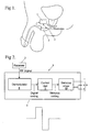
- Referring in general to Figs 1 to 6, there is illustrated an
implantable sphincter stimulator 1 for selectively providing electrical stimulation to an innervatedsmooth muscle sphincter 2 disposed about aurethra 3 for controlling the flow of urine. -
Stimulator 1 includes asignal processing unit 4 in electrical communication with areceiver 5.Signal processing unit 4 is configured to provide a predetermined electrical stimulation signal at afirst output 6 ofstimulator 1 in response to a signal generated remotely bycontroller 7 and applied atreceiver 5 such thatprocessing unit 4 selectively provides the stimulation signal to eithercontract sphincter 2 to substantially block the flow of urine along theurethra 3 or to allowsphincter 2 to relax and allow urine to flow. - Referring to Fig 2 particularly,
signal processing unit 4 includes ademodulator 8 responsive to the signal received atreceiver 5 for providing a modulated signal to astimulus encoder 9 which in turn provides a signal to astimulus driver 10 which provides the stimulated signal atsphincter stimulator output 6. - Once
sphincter 2 is allowed to relax, processingunit 4 includes means to supply a stimulation signal atoutput 6 to contractsphincter 2 when a predetermined signal to contract the sphincter is not received bysignal processing unit 4 viareceiver 5 for a predetermined time period. In the preferred implementation, theprocessing unit 4 provides stimuli adapted to contract the sphincter unless a signal is received, in response to which the stimuli is turned off, and the sphincter relaxes. - The signal is communicated to
sphincter stimulator 1 by means of radio frequency waves andreceiver 5 is an RF receiver. If the casing of the stimulator is made of titanium, and the receiver is inside, then a frequency of 8-10 kHz is preferred. If the casing is made of silicone rubber or the like, then 8-10 MHz is preferred. - In other embodiments of the invention, the signal may be communicated optically in the range 630nm to 1400nm to
sphincter stimulator 1 andreceiver 5 is a photon detector in the form of a PMT, photo-diode or other suitable detector. - In yet other embodiments of the invention, the signal is communicated to
sphincter stimulator 1 by microwave means andreceiver 5 is a microwave receiver. In such embodiments, the microwave signal has a frequency in the range of 0.9 to 2.5 GHz. Alternatively, the signal is communicated tosphincter stimulator 1 by magnetic means andreceiver 5 is a magnetic energy receiver. Any other suitable communication arrangement may be used. - As is best illustrated in Fig 3,
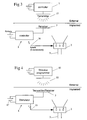
controller 7 includes the RF transmitter which is driven by a means for generating the control signal.Controller 7 further includes actuation means for selectively generating the control signal attransmitter 11. - Part of
transmitter 11 is also a receiver for receiving an information signal indicative of at least one parameter of the sphincter stimulator and provided by the sphincter stimulator. The telemetry information signal is transmitted to the controller by means of a transmitter disposed withinreceiver 5. In embodiments of the invention where microwaves are employed to communicate either the control signal or telemetry information signal,transceiver 11 ofcontroller 7 is configured to transmit and receive microwave radiation. In embodiments where the control signal is transmitted optically,transceiver 11 includes a photon detector in the form of a PMT or solid state device and a light source having a predetermined output. In embodiments of the invention where the control signal and the sphincter stimulator information signal are transmitted by magnetic energy, thetransmitter receiver 5 functions as a passive proximity card andcontroller 7 functions as the active proximity card reader. - Fig 2 illustrates a stimulation signal in the form of a pulse. The pulse is generally rectangular and symmetrically biphasic. In other embodiments of the invention, not illustrated,
sphincter stimulator 1 provides multiple channel pulse generation atoutput 6. The stimulation signal is selected so as to provide a substantially continuous tone in the sphincter. - The stimulation signal provided at
output 6 has a substantially constant current less that or equal to 30mA, and preferably of the order of 15mA. - The stimulation pulse frequency provided to
sphincter 1 byoutput 6 is in the range of 0.25Hz to 2.5Hz and is preferably 2Hz. The stimulation pulse width is in the range of 0.05 ms to 0.2 ms and is preferably 0.15 ms. It should be noted that the device is current regulated, and accordingly the stimulation voltage will vary with the resistance of the muscle tissue between the electrodes. Typical values for the voltage are between 0.2 and 7 volts. - It should be noted, however, that these parameters are variable and are configured for each person.
- Preferably, the smooth muscle is taken from the smooth muscle of the bladder and transplanted about the urethra and having its circulation intact. Alternatively, the muscle may be venous smooth, anococcygeus smooth muscle, terminal ileum transplanted as a segment devoid of mucosa and having its circulation intact. A further alternative is the dartos smooth muscle from the scrotum or labia. Any other suitable muscle may be employed. In each case, the long axes of the muscle cells are disposed substantially circumferentially about the sphincter.
- The muscle is generally in the form of a rectangular strip such that the long axes of the muscle cells are disposed substantially lengthwise along the strip. The muscle is then disposed substantially fully around the urethra in a generally cylindrical arrangement such that the long axes of the muscle cells are substantially circumferencially disposed about the urethra. Preferably, the strip is completely disposed around the urethra.
- The muscle strip has dimensions 6cm by 2cm and is preferably provided in the range from 4.5cm to 7.5cm by 1.25cm to 2.25cm.
- The stimulation signal is provided at
output 6 ofsphincter stimulator 1 is supplied tosphincter 2 by an electrode implanted into the sphincter at a predetermined location and anelectrical lead 16 being disposed intermediate. As is best illustrated in Fig 6, lead 16 includes three electrodes disposed in a tripolar configuration aboutsphincter 2 and having means to electrically connect to lead 16. In other embodiments of the invention, the three electrodes are disposed in a cuff or epimysal configuration about the sphincter. - Electrode leads may extend between the pulse generator and the electrodes, allowing some "slackness" in their length to account for normal body movements.
- As is best illustrated in Figs 5 and 6, the configuration of the electrodes are disposed in a tripolar configuration. Simple tripolar electrodes are the least expensive alternative, are relatively easy to implant and can be used to stimulate the transplanted smooth muscle. Their exposed metallic surfaces usually consist of a cathode aligned between two anodes.
- In the epimysial configuration, the electrodes are sutured directly onto the surface of a muscle. These electrodes are implemented when stimulation of a motor nerve trunk is impractical, however, this is not necessarily always the case.
- In the cuff electrode configurations are employed in alternative embodiments and are contained within an insulating sheath substantially circumferentially around the circumference of the transplanted sphincter. They are capable of stimulating the embedded nerve fibres maximally while keeping the stimulus field local to the transplant.
- In other embodiments of the invention, not illustrated, the sphincter stimulator includes a second output such that one of the sphincter stimulator outputs provides a signal to contract the sphincter and the other output provides a stimulation signal to allow the sphincter to relax or contract to a lesser extent. In this embodiment, each of the first and second outputs of the sphincter stimulator each include a lead having three outputs in a tripolar configuration about the sphincter. In yet other embodiments, the first and second outputs each include a lead having three electrodes disposed in a cuff or epimysal configuration about the sphincter.
- It will be appreciated that in normal use, only two of the three electrodes will be used to deliver stimuli. The third electrode is provided as a spare, in the event that one of the electrodes ceases to function. However, it is contemplated that the present invention could use a more complicated set of stimuli, or more electrodes.
-
Sphincter stimulator 1 includes a replaceablebattery power source 17, not illustrated in Fig 2. In one implementation,battery 17 is in electrical communication withsignal processing unit 4 such that the control signal provided bycontroller 7 tosphincter stimulator 1 inductively provides energy to recharge the battery. In another implementation, in the case of radio frequency transceiving between the and sphincter stimulators, the signal is provided by modulating the RF signal such that the signal processing unit extracts the control signal and provides the battery with remaining power from the RF signal. - As is best illustrated in Fig 4,
RF transceiver 5 ofstimulator 1 is communicable with a third output ofprocessing unit 4 for transmitting sphincter stimulator telemetry information indicative of one or more the parameters of the sphincter stimulator for remote detection. The information is transmitted by radio frequency signals, however, in other embodiments of the invention the sphincter stimulator information is transmitted by microwave means, optical means or by magnetic energy. The sphincter stimulator information signal includes information regarding parameters such as stimulation signal-frequency, current, width and/or shape, and received signal strength and battery status. This is useful for use in a controller intended for use by physicians. - A remote sphincter
stimulator programming unit 13 is adapted to receive the sphincter stimulator information provided byreceiver 5. The sphincter stimulator programming unit includes a transceiver 14 for providing a calibration signal tostimulator 1 which, in response, selectively varies one or more of the output properties ofstimulator 1. The calibration signal is preferably transmitted in response to receiving the sphincter stimulator telemetry information. The calibration signal includes coding to selectively vary the output current, shape, frequency and/or width. Conveniently, the remote sphincter stimulator programming unit is integrated into the physician controller. - The preferred embodiments of the invention also provide a method of treating urinary incontinence in a person including the steps of disposing the implanted smooth muscle sphincter substantially around a urethra, locating a plurality of electrodes in predetermined locations in the sphincter and electrically connecting them with an implanted sphincter stimulator as hereinbefore described.
- The sphincter stimulator is then selectively actuated on receipt of the control signal to provide the predetermined stimulation signal to either contract the sphincter or allow it to relax. The method includes providing the stimulation signal to contract the urethra or allow it to relax from
output 6 ofsphincter stimulator 1. In other embodiments of the invention, however, the stimulation signal to contract the sphincter about the urethra is provided by a separate output ofsphincter stimulator 1 to that which provides a stimulation signal to allow the urethra to relax. - There is also provided a method of surgically implanting a sphincter stimulator system as hereinbefore described in a person for treating incontinence, the method including the steps of implanting the smooth muscle sphincter substantially about the urethra in a person, implanting the sphincter stimulator in the person proximal to the implanted sphincter and implanting electrodes into the sphincter at predetermined locations and electrically connecting the sphincter stimulator with the smooth muscle sphincter.
- Other preferred embodiments provide a stimulus system including circuit means defining a single channel electrical pulse generator, power supply means, a control circuit to allow a transplanted sphincter to relax, a separate control circuit to adjust pulse parameters, two or more stimulus electrodes, and leads connecting the stimulator to the electrodes.
- The prosthetic sphincter includes a sheath of innervated or reinnervatable muscle tissue taken from the selected muscle and transplanted around the urethra. In one embodiment, a segment of distal small intestine, 2-3 cm long, on a vascular pedicle is isolated and the remaining intestine is rejoined by end to end anastomosis. The isolated segment is opened along its antimesenteric border and the mucosa is dissected away.
- The isolated segment is drawn down to the neck of the bladder. It is then taken around the bladder neck, so that the circular muscle is disposed substantially circumferentially with respect to the neck, and the cut antimesenteric borders are sewn together to create a close fit around the neck of the bladder. If necessary, the circumferential length is reduced to create a close fit. The newly created and vascularised sphincter is secured in place by sewing it to the superficial connective tissue of the bladder neck. A stimulating electrode assembly is sewn to the transplanted intestine, with the axis of the electrode assembly at right angles to the circular muscle, adjacent to the entry of the vessels from the vascular pedicle. The anchoring ligatures penetrate the sphincter and are secured to the underlying bladder neck.
- In an alternative embodiment, the sphincter augmentation is made by dissecting the anococcygeus muscles from their spinal insertions, and drawing the freed muscle around the bladder neck. The sphincter may also be created from a section of muscular vein, venous smooth muscle, the terminal ilium and transplanted as a segment devoid of mucosa and having its circulation intact, or the dartos smooth muscle from the scrotum or labia.
- The stimulus pulse generator transfers electrical pulses to the electrodes and these pulses are converted into action potentials in the nerves transplanted with the muscle sphincter or in the nerves which re-innervate the sphincter after surgery.
- All implanted circuitry is preferably sealed and encased in a biologically inert material such as a biocompatible silicone material. The metallic electrodes and leads are preferably of Platinum-Iridium alloy. The connecting wires are preferably insulated with a silicone coating and lead to an implanted control unit placed between the abdominal muscle and skin.
- The stimulator is required to maintain continuous tone in the transplanted sphincter sufficient to hold urine in the bladder without leakage by continuous stimulation. To release urine, an external control unit using, for example, a radio frequency signal will turn off the internal unit to halt the stimulation of the sphincter, and is shown schematically in Fig 3.
- Alternative embodiments of the invention employ microwave or optical means, for example, in the form of infra-red radiation, to communicate the control signal to the sphincter stimulator, and the sphincter stimulator includes a corresponding receiver at or near the skin of the person.
- The person would hold the external device adjacent the skin over the implant (and push an actuation button) to allow the transplanted sphincter to relax and urine to flow. After bladder emptying, the patient would then push the button again to resume sphincteric pressure. As described, if the user forgets to push the button to close the sphincter, the stimulator could be programmed to resume operation automatically after a given time.
- The advantages of this system are twofold. Firstly, the patient does not need to hold the external control unit against their skin for the whole period of bladder emptying. They simply initiate the process and can then put the unit aside if desired. The second advantage is that such a system allows the stimulator circuitry to be adjusted externally.
- In embodiments where the signal is communicated magnetically, a permanent magnet is placed on the surface of the skin directly over the location of the implanted control circuit. The circuit is designed to detect the presence of the magnetic field and shut off the stimulation accordingly. To empty the bladder, therefore, the person simply places a magnet over the implant for the time period required to empty the bladder. A small permanent magnet is a convenient item to carry around and requires no batteries. One disadvantage of such a system is that a magnetic detector needs to be added to the implanted device and this, in turn, requires more power from the internal batteries.
- It is envisaged that the requirements of the stimulator may change, both post-operatively and with alteration of the preserved sphincteric resistance as the person ages. Access to the implanted device via surgery for the purpose of hardware adjustment is, of course, undesirable. Therefore, adjustment of the stimulus parameters via an external radio link to the sphincter
stimulator programming unit 13 is a preferred feature of the system. - It will be appreciated that various modifications and alterations may be made to the system described above without departing from the scope of the invention.
Claims (33)
- An implantable sphincter stimulator (1) configured for operatively providing electrical stimulation to a surgically implanted innervated smooth muscle sphincter so as to control the flow of a bodily substance therethrough, the stimulator including:a stimulus generating unit (4) in electrical communication with a receiver (5), the stimulus generating unit operatively configured to provide a first predetermined electrical stimulation signal adapted to contract said sphincter, and a second predetermined signal adapted to allow said sphincter to relax, one of said predetermined signals being selected in response to a control signal received at the receiver from a remote controller.
- A sphincter stimulator according to claim 1 wherein the surgically implanted innervated smooth muscle sphincter is disposed about the urethra so as to control the flow of urine therethrough.
- A sphincter stimulator according to claim 1 or 2 wherein the stimulation signal is such as to provide a continuous tone in said sphincter.
- A sphincter stimulator according to any one of the preceding claims wherein the stimulation signal is pulsatile.
- A sphincter stimulator according to claim 4 wherein the stimulation signal is generally rectangular and symmetrical biphasic.
- A sphincter stimulator according to any one of the preceding claims wherein the control signal is communicated optically, magnetically, by RF or by microwave.
- A sphincter stimulator according to any one of the preceding claims wherein the stimulus generating unit includes a demodulator responsive to the received signal for providing a modulated signal to a stimulus encoder which in turn provides a signal to a stimulus driver which provides the stimulation signal at selected ones of the stimulator outputs.
- A sphincter stimulator according to any one of the preceding claims wherein, after the sphincter has relaxed, the stimulator includes means to supply the first stimulation signal at a selected one of its outputs to contract the sphincter when a predetermined signal to contract the sphincter is not received by the receiver for a predetermined period.
- A sphincter stimulator according to any one of the preceding claims including a transmitter for transmitting sphincter stimulator telemetry information indicative of one or more parameters of the stimulator for detection remotely.
- A sphincter stimulator according to claim 9 wherein the telemetry information is transmitted by the same communications means as the control signal.
- A sphincter stimulator according to claim 9 or 10 wherein the parameters include one or more of the stimulation signal frequency, current, width and/or shape, or received signal strength or battery status.
- A sphincter stimulator according to any one of claims 9 to 11 wherein the receiver is configured to accept a remotely generated sphincter stimulator calibration signal and in response, a signal processing unit selectively varies one or more of the output properties of the sphincter stimulator.
- A sphincter stimulator according to claim 12 wherein the calibration signal is transmitted in response to received sphincter stimulator telemetry information.
- A sphincter stimulator according to any one of the preceding claims wherein the stimulation generating unit is operatively connected to the sphincter by one or more electrical leads, each having one or more electrodes.
- A sphincter stimulator according to claim 14 wherein the lead includes three electrodes disposed about the sphincter in a configuration selected from one of the following: epimysal configuration, cuff configuration, or tripolar configuration.
- A sphincter stimulator according to anyone of the preceding claims wherein the second predetermined signal is the absence of a stimulation.
- A system for use in treating inadequate sphincter function in a person, the system including:a portion of innervated smooth muscle tissue configured to define a sphincter and implanted so as to control the flow of a bodily substance therethrough;an implanted sphincter stimulator (1) arranged so as to allow electrical stimuli to be applied to the sphincter; anda non-implanted controller (7) in communication with the sphincter stimulator for selectively triggering the generation of predetermined electrical stimulation signals to respectively contract the sphincter or allow the sphincter to relax.
- A system according to claim 17 wherein the implanted innervated smooth muscle sphincter is disposed about the urethra of the person.
- A system according to claim 17 or 18 wherein the muscle is in the form of a strip.
- A system according to claim 19 wherein the strip is generally rectangular.
- A system according to any one of claims 17 to 20 wherein the muscle is disposed substantially fully around the sphincter in a generally cylindrical arrangement.
- A system according to claim 21 wherein the long axes of the muscle cells are substantially circumferentially aligned.
- A system according to any one of claims 17 to 22 wherein the smooth muscle is taken from the terminal ileum and transplanted as a segment devoid of mucosa and having its circulation intact.
- A system according to any one of claims 17 to 22 wherein the muscle is selected from the group consisting of venous smooth muscle, anococcygeus smooth muscle, smooth muscle from the bladder, and dartos muscle taken from the scrotum or labia.
- A system according to any one of claims 17 to 24 wherein the sphincter stimulator is in accordance with any one of claims 1 to 16.
- A system according to any one of claims 17 to 25 wherein the controller includes:a transmitter;means for generating a predetermined control signal at the transmitter;a power source; andactuation means for selectively generating the control signal such that on receipt of the signal, the sphincter stimulator provides the stimulation signal at its output in order to contract the sphincter or allow it to relax.
- A system according to any one of claims 17 to 26 wherein the controller includes a receiver for receiving a stimulator information telemetry signal from the sphincter stimulator.
- A system according to any one of claims 24 to 27 wherein the control signal is transmitted, optically, magnetically, by radio waves, or by microwaves.
- A system according to any one of claims 24 to 28 including a remote sphincter stimulator programming unit for selectively programming the sphincter stimulator to provide a predetermined output in response to the control signal.
- A system according to claim 29 wherein one or more of the stimulation signal current, shape, frequency and width is variable in response to a calibration signal provided by the programming unit.
- A system according to claim 29 or 30 wherein the programming unit includes a transceiver for providing the programming signal to the stimulator.
- A system according to any one of claims 29 to 31 wherein the programming unit is the controller.
- A system according to any one of claims 17 to 32 wherein the signal to allow the sphincter to relax is the absence of a stimulation.
Applications Claiming Priority (3)
| Application Number | Priority Date | Filing Date | Title |
|---|---|---|---|
| AUPQ2026A AUPQ202699A0 (en) | 1999-08-04 | 1999-08-04 | Prosthetic device for incontinence |
| AUPQ202699 | 1999-08-04 | ||
| PCT/AU2000/000925 WO2001010357A1 (en) | 1999-08-04 | 2000-08-04 | Method and apparatus for treating incontinence |
Publications (3)
| Publication Number | Publication Date |
|---|---|
| EP1207822A1 EP1207822A1 (en) | 2002-05-29 |
| EP1207822A4 EP1207822A4 (en) | 2006-05-10 |
| EP1207822B1 true EP1207822B1 (en) | 2007-10-24 |
Family
ID=3816206
Family Applications (1)
| Application Number | Title | Priority Date | Filing Date |
|---|---|---|---|
| EP00947688A Expired - Lifetime EP1207822B1 (en) | 1999-08-04 | 2000-08-04 | Method and apparatus for treating incontinence |
Country Status (9)
| Country | Link |
|---|---|
| US (4) | US6659936B1 (en) |
| EP (1) | EP1207822B1 (en) |
| JP (1) | JP2003506145A (en) |
| AT (1) | ATE376405T1 (en) |
| AU (1) | AUPQ202699A0 (en) |
| CA (1) | CA2378388C (en) |
| DE (1) | DE60036873T2 (en) |
| NZ (1) | NZ517128A (en) |
| WO (1) | WO2001010357A1 (en) |
Families Citing this family (115)
| Publication number | Priority date | Publication date | Assignee | Title |
|---|---|---|---|---|
| US6941171B2 (en) * | 1998-07-06 | 2005-09-06 | Advanced Bionics Corporation | Implantable stimulator methods for treatment of incontinence and pain |
| IL127481A (en) | 1998-10-06 | 2004-05-12 | Bio Control Medical Ltd | Incontinence treatment device |
| AU6118799A (en) * | 1998-10-06 | 2000-04-26 | Bio Control Medical, Ltd. | Incontinence treatment device |
| AUPQ202699A0 (en) * | 1999-08-04 | 1999-08-26 | University Of Melbourne, The | Prosthetic device for incontinence |
| US6471635B1 (en) | 2000-02-10 | 2002-10-29 | Obtech Medical Ag | Anal incontinence disease treatment with controlled wireless energy supply |
| US6450173B1 (en) | 1999-08-12 | 2002-09-17 | Obtech Medical Ag | Heartburn and reflux disease treatment with controlled wireless energy supply |
| US6464628B1 (en) | 1999-08-12 | 2002-10-15 | Obtech Medical Ag | Mechanical anal incontinence |
| US6482145B1 (en) | 2000-02-14 | 2002-11-19 | Obtech Medical Ag | Hydraulic anal incontinence treatment |
| WO2001058388A1 (en) | 2000-02-10 | 2001-08-16 | Potencia Medical Ag | Urinary incontinence treatment with wireless energy supply |
| EP1253877B1 (en) | 2000-02-10 | 2005-05-11 | Potencia Medical AG | Mechanical impotence treatment apparatus |
| MXPA02007589A (en) | 2000-02-10 | 2004-08-23 | Potencia Medical Ag | Controlled urinary incontinence treatment. |
| US7931582B2 (en) | 2000-02-11 | 2011-04-26 | Obtech Medical Ag | Controlled impotence treatment |
| US20030125768A1 (en) | 2000-02-11 | 2003-07-03 | Forsell Peter | Impotence treatment apparatus with energy transforming means |
| US7442165B2 (en) | 2000-02-14 | 2008-10-28 | Obtech Medical Ag | Penile prosthesis |
| US20030100929A1 (en) * | 2000-02-14 | 2003-05-29 | Peter Forsell | Controlled penile prosthesis |
| WO2001047440A2 (en) | 2000-02-14 | 2001-07-05 | Potencia Medical Ag | Male impotence prosthesis apparatus with wireless energy supply |
| US6907295B2 (en) * | 2001-08-31 | 2005-06-14 | Biocontrol Medical Ltd. | Electrode assembly for nerve control |
| SE0102312D0 (en) * | 2001-06-28 | 2001-06-28 | Obtech Medical Ag | Urinary dysfunction treatment apparatus |
| US7499753B2 (en) | 2001-06-28 | 2009-03-03 | Urologica Ag | Urinary Dysfunction Treatment Apparatus |
| US20050055063A1 (en) * | 2001-07-20 | 2005-03-10 | Loeb Gerald E. | Method and apparatus for the treatment of urinary tract dysfunction |
| US7778703B2 (en) * | 2001-08-31 | 2010-08-17 | Bio Control Medical (B.C.M.) Ltd. | Selective nerve fiber stimulation for treating heart conditions |
| US6862480B2 (en) | 2001-11-29 | 2005-03-01 | Biocontrol Medical Ltd. | Pelvic disorder treatment device |
| IL162193A0 (en) * | 2001-11-29 | 2005-11-20 | Biocontrol Medical Ltd | Pelvic disorder treatment device |
| US7608067B2 (en) * | 2002-11-06 | 2009-10-27 | Aram Bonni | Patient-adjustable incontinence device (AID) |
| US7627384B2 (en) | 2004-11-15 | 2009-12-01 | Bio Control Medical (B.C.M.) Ltd. | Techniques for nerve stimulation |
| US8880192B2 (en) | 2012-04-02 | 2014-11-04 | Bio Control Medical (B.C.M.) Ltd. | Electrode cuffs |
| US20060149124A1 (en) * | 2003-01-31 | 2006-07-06 | Peter Forsell | Electrically operable impotence treatment apparatus |
| US20060142635A1 (en) * | 2003-01-31 | 2006-06-29 | Peter Forsell | Electrically operable incontinence treatment apparatus |
| US7241260B2 (en) | 2003-09-19 | 2007-07-10 | Neopraxis Pty. Limited | Sphincteric control system |
| US8116881B2 (en) | 2004-06-10 | 2012-02-14 | Bio Control Medical (B.C.M.) Ltd | Electrode assembly for nerve control |
| US20050283202A1 (en) * | 2004-06-22 | 2005-12-22 | Gellman Barry N | Neuromodulation system |
| US7955357B2 (en) | 2004-07-02 | 2011-06-07 | Ellipse Technologies, Inc. | Expandable rod system to treat scoliosis and method of using the same |
| EP1784143A2 (en) * | 2004-08-25 | 2007-05-16 | Pavad Medical, Inc. | Artificial sphincter |
| US7368279B2 (en) * | 2004-11-24 | 2008-05-06 | The Regents Of The University Of Michigan | Three dimensional bioengineered smooth muscle tissue and sphincters and methods therefor |
| US7515965B2 (en) | 2005-02-23 | 2009-04-07 | Medtronic, Inc. | Implantable medical device providing adaptive neurostimulation therapy for incontinence |
| EP1853344A4 (en) * | 2005-03-02 | 2008-05-28 | Continence Control Systems Int | Improved method and apparatus for treating incontinence |
| US20060264982A1 (en) * | 2005-05-20 | 2006-11-23 | Viola Frank J | Gastric restrictor assembly and method of use |
| US7666180B2 (en) * | 2005-05-20 | 2010-02-23 | Tyco Healthcare Group Lp | Gastric restrictor assembly and method of use |
| US7691053B2 (en) * | 2005-05-20 | 2010-04-06 | Tyco Healthcare Group Lp | Gastric restrictor assembly and method of use |
| WO2007019613A1 (en) * | 2005-08-15 | 2007-02-22 | Continence Control Systems International Pty Ltd | Method and apparatus for controlling a bodily function |
| US20070173903A1 (en) * | 2005-08-30 | 2007-07-26 | Bioq, Inc. | Medical device for restoration of neurological function impaired by peripheral neuropathy |
| JP2009506805A (en) * | 2005-09-02 | 2009-02-19 | コンティネンス コントロール システムズ インターナショナル プロプライエタリー リミテッド | Smooth muscle implants for managing medical conditions |
| US20070073361A1 (en) * | 2005-09-23 | 2007-03-29 | Bioq, Inc. | Medical device for restoration of autonomic and immune functions impaired by neuropathy |
| EP1933897A4 (en) * | 2005-10-14 | 2009-07-29 | Continence Control Systems Int | A method and apparatus for treating a heart condition |
| JP2009511132A (en) * | 2005-10-14 | 2009-03-19 | コンティネンス コントロール システムズ インターナショナル プロプライエタリー リミテッド | Method and apparatus for the treatment of fecal incontinence |
| US20070100388A1 (en) * | 2005-10-31 | 2007-05-03 | Medtronic, Inc. | Implantable medical device providing adaptive neurostimulation therapy for incontinence |
| AU2007204602A1 (en) * | 2006-01-16 | 2007-07-19 | Continence Control Systems International Pty Limited | A stimulator for the control of a bodily function |
| US8195296B2 (en) | 2006-03-03 | 2012-06-05 | Ams Research Corporation | Apparatus for treating stress and urge incontinence |
| US20070265675A1 (en) * | 2006-05-09 | 2007-11-15 | Ams Research Corporation | Testing Efficacy of Therapeutic Mechanical or Electrical Nerve or Muscle Stimulation |
| US8160710B2 (en) | 2006-07-10 | 2012-04-17 | Ams Research Corporation | Systems and methods for implanting tissue stimulation electrodes in the pelvic region |
| US20100076255A1 (en) * | 2006-09-12 | 2010-03-25 | Continence Control Systems International Pty Ltd | Method and apparatus for treating a prolapse related condition |
| US7862502B2 (en) | 2006-10-20 | 2011-01-04 | Ellipse Technologies, Inc. | Method and apparatus for adjusting a gastrointestinal restriction device |
| US8246533B2 (en) * | 2006-10-20 | 2012-08-21 | Ellipse Technologies, Inc. | Implant system with resonant-driven actuator |
| US8435203B2 (en) * | 2007-06-20 | 2013-05-07 | Covidien Lp | Gastric restrictor assembly and method of use |
| US20100049289A1 (en) | 2007-07-10 | 2010-02-25 | Ams Research Corporation | Tissue anchor |
| US9427573B2 (en) | 2007-07-10 | 2016-08-30 | Astora Women's Health, Llc | Deployable electrode lead anchor |
| CA2739945A1 (en) * | 2007-10-11 | 2009-04-16 | Peter Forsell | Device and method for embryo control |
| WO2009048388A1 (en) * | 2007-10-11 | 2009-04-16 | Milux Holding Sa | An apparatus for male contraception |
| US8696543B2 (en) | 2007-10-11 | 2014-04-15 | Kirk Promotion Ltd. | Method for controlling flow of intestinal contents in a patient's intestines |
| US8795153B2 (en) | 2007-10-11 | 2014-08-05 | Peter Forsell | Method for treating female sexual dysfunction |
| WO2010042045A1 (en) | 2008-10-10 | 2010-04-15 | Milux Holding S.A. | A system, an apparatus, and a method for treating a sexual dysfunctional female patient |
| SI2211768T1 (en) | 2007-10-11 | 2021-11-30 | Implantica Patent Ltd. | Apparatus for controlling flow in a bodily organ |
| US8992409B2 (en) | 2007-10-11 | 2015-03-31 | Peter Forsell | Method for controlling flow in a bodily organ |
| US8057472B2 (en) | 2007-10-30 | 2011-11-15 | Ellipse Technologies, Inc. | Skeletal manipulation method |
| US7765006B2 (en) * | 2007-12-13 | 2010-07-27 | Leto Medical, Llc | Method and apparatus for providing continence to a gastrointestinal ostomy |
| CA3187608A1 (en) * | 2008-01-28 | 2009-08-06 | Implantica Patent Ltd. | An implantable drainage device |
| WO2009096857A1 (en) | 2008-01-29 | 2009-08-06 | Milux Holding Sa | A device, system and method for treating obesity |
| US11202707B2 (en) | 2008-03-25 | 2021-12-21 | Nuvasive Specialized Orthopedics, Inc. | Adjustable implant system |
| US20090248148A1 (en) | 2008-03-25 | 2009-10-01 | Ellipse Technologies, Inc. | Systems and methods for adjusting an annuloplasty ring with an integrated magnetic drive |
| US20090259093A1 (en) * | 2008-04-14 | 2009-10-15 | Bhat Nikhil D | Artificial sphincter with piezoelectric actuator |
| WO2010042686A1 (en) | 2008-10-09 | 2010-04-15 | Sharma Virender K | Method and apparatus for stimulating the vascular system |
| US10603489B2 (en) | 2008-10-09 | 2020-03-31 | Virender K. Sharma | Methods and apparatuses for stimulating blood vessels in order to control, treat, and/or prevent a hemorrhage |
| WO2010042058A1 (en) | 2008-10-10 | 2010-04-15 | Milux Holding S.A. | An improved artificial valve |
| US8696745B2 (en) | 2008-10-10 | 2014-04-15 | Kirk Promotion Ltd. | Heart help device, system, and method |
| PL2346456T3 (en) * | 2008-10-10 | 2021-11-08 | Implantica Patent Ltd. | An apparatus for temporary male contraception |
| EP2349078A4 (en) | 2008-10-10 | 2018-02-07 | Kirk Promotion LTD. | Fastening means for implantable medcial control assembly |
| CA3004121C (en) | 2008-10-10 | 2020-06-16 | Medicaltree Patent Ltd. | Heart help device, system, and method |
| US8600510B2 (en) | 2008-10-10 | 2013-12-03 | Milux Holding Sa | Apparatus, system and operation method for the treatment of female sexual dysfunction |
| US8372093B2 (en) * | 2008-11-04 | 2013-02-12 | Koletry Processing L.L.C. | Systems and processes for controlling gastric bands based on geographic location |
| US8382756B2 (en) | 2008-11-10 | 2013-02-26 | Ellipse Technologies, Inc. | External adjustment device for distraction device |
| US8197490B2 (en) | 2009-02-23 | 2012-06-12 | Ellipse Technologies, Inc. | Non-invasive adjustable distraction system |
| US20100217340A1 (en) * | 2009-02-23 | 2010-08-26 | Ams Research Corporation | Implantable Medical Device Connector System |
| US9539433B1 (en) | 2009-03-18 | 2017-01-10 | Astora Women's Health, Llc | Electrode implantation in a pelvic floor muscular structure |
| US9327117B2 (en) * | 2009-04-24 | 2016-05-03 | Medtronic, Inc. | Bladder sensing using impedance and posture |
| US9622792B2 (en) | 2009-04-29 | 2017-04-18 | Nuvasive Specialized Orthopedics, Inc. | Interspinous process device and method |
| US10952836B2 (en) | 2009-07-17 | 2021-03-23 | Peter Forsell | Vaginal operation method for the treatment of urinary incontinence in women |
| US9949812B2 (en) | 2009-07-17 | 2018-04-24 | Peter Forsell | Vaginal operation method for the treatment of anal incontinence in women |
| US8277426B2 (en) | 2009-09-30 | 2012-10-02 | Wilcox Heather J | Male urinary incontinence device |
| US8380312B2 (en) | 2009-12-31 | 2013-02-19 | Ams Research Corporation | Multi-zone stimulation implant system and method |
| US9248043B2 (en) | 2010-06-30 | 2016-02-02 | Ellipse Technologies, Inc. | External adjustment device for distraction device |
| US8734488B2 (en) | 2010-08-09 | 2014-05-27 | Ellipse Technologies, Inc. | Maintenance feature in magnetic implant |
| US8852187B2 (en) | 2011-02-14 | 2014-10-07 | Ellipse Technologies, Inc. | Variable length device and method |
| US9220887B2 (en) | 2011-06-09 | 2015-12-29 | Astora Women's Health LLC | Electrode lead including a deployable tissue anchor |
| EP2753397B1 (en) | 2011-09-08 | 2017-01-11 | AMS Research Corporation | Implantable electrode assembly |
| US10743794B2 (en) | 2011-10-04 | 2020-08-18 | Nuvasive Specialized Orthopedics, Inc. | Devices and methods for non-invasive implant length sensing |
| WO2013066946A1 (en) | 2011-11-01 | 2013-05-10 | Ellipse Technologies, Inc. | Adjustable magnetic devices and methods of using same |
| EP2790773B1 (en) | 2012-01-25 | 2020-10-14 | Nevro Corporation | Lead anchor |
| US10576278B2 (en) | 2012-02-21 | 2020-03-03 | Virender K. Sharma | System and method for electrical stimulation of anorectal structures to treat urinary dysfunction |
| US9782583B2 (en) | 2012-02-21 | 2017-10-10 | Virender K. Sharma | System and method for electrical stimulation of anorectal structures to treat urinary dysfunction |
| US8706234B2 (en) | 2012-02-21 | 2014-04-22 | Virender K. Sharma | System and method for electrical stimulation of anorectal structures to treat anal dysfunction |
| BR112015009446B1 (en) | 2012-10-29 | 2021-07-20 | Nuvasive Specialized Orthopedics, Inc. | SYSTEM FOR CHANGING AN ANGLE OF A SUBJECT'S BONE |
| US10327881B2 (en) | 2013-03-12 | 2019-06-25 | Boston Scientific Scimed, Inc. | Implantable medical device and methods of delivering an implantable medical device |
| US9265935B2 (en) | 2013-06-28 | 2016-02-23 | Nevro Corporation | Neurological stimulation lead anchors and associated systems and methods |
| US10751094B2 (en) | 2013-10-10 | 2020-08-25 | Nuvasive Specialized Orthopedics, Inc. | Adjustable spinal implant |
| EP3137000B1 (en) | 2014-04-28 | 2023-08-23 | NuVasive Specialized Orthopedics, Inc. | System for informational magnetic feedback in adjustable implants |
| EP4005515A1 (en) | 2014-12-26 | 2022-06-01 | NuVasive Specialized Orthopedics, Inc. | Systems for distraction |
| WO2016134326A2 (en) | 2015-02-19 | 2016-08-25 | Nuvasive, Inc. | Systems and methods for vertebral adjustment |
| EP4218609A1 (en) | 2015-10-16 | 2023-08-02 | NuVasive Specialized Orthopedics, Inc. | Adjustable devices for treating arthritis of the knee |
| KR20180093988A (en) | 2015-12-10 | 2018-08-22 | 누베이시브 스페셜라이즈드 오소페딕스, 인크. | External adjustment device for distraction device |
| EP3407812B1 (en) | 2016-01-28 | 2020-07-01 | NuVasive Specialized Orthopedics, Inc. | Systems for bone transport |
| US9750591B1 (en) | 2016-07-29 | 2017-09-05 | Sam Sultan | Systems and methods for assisting patients in emptying their bladder efficiently |
| US11896823B2 (en) | 2017-04-04 | 2024-02-13 | Btl Healthcare Technologies A.S. | Method and device for pelvic floor tissue treatment |
| US10490307B1 (en) | 2018-08-08 | 2019-11-26 | International Business Machines Corporation | Cognitive-based tools for care and charge of incontinent individuals or animals |
| CN113613597A (en) * | 2019-01-29 | 2021-11-05 | 伯尔尼大学 | Urinary pumping device |
| WO2021080865A1 (en) | 2019-10-22 | 2021-04-29 | Hologic, Inc. | Transvaginal treatment of stress urinary incontinence |
Family Cites Families (47)
| Publication number | Priority date | Publication date | Assignee | Title |
|---|---|---|---|---|
| GB1434524A (en) | 1972-04-27 | 1976-05-05 | Nat Res Dev | Urinary control apparatus |
| SE7604553L (en) | 1976-04-21 | 1977-10-22 | Svenska Utvecklings Ab | ELECTRICAL STIMULATOR FOR REDUCING INCONTINENCE |
| US4153059A (en) | 1977-10-25 | 1979-05-08 | Minnesota Mining And Manufacturing Company | Urinary incontinence stimulator system |
| US4256093A (en) | 1978-10-12 | 1981-03-17 | The United States Of America As Represented By The Administrator Of The National Aeronautics And Space Administration | Prosthetic urinary sphincter |
| NL8002039A (en) * | 1980-04-08 | 1981-11-02 | Philips Nv | OPTICALLY READABLE INFORMATION DISC. |
| YU272580A (en) | 1980-10-23 | 1982-10-31 | Inst Jozef Stefan | Control circuit of a therapeutic stimulator for urine incontinency |
| US4688575A (en) | 1982-03-12 | 1987-08-25 | Duvall Wilbur E | Muscle contraction stimulation |
| DE3379831D1 (en) | 1982-10-14 | 1989-06-15 | Steindorf Susanne Ruth | Device for galvanic electro-stimulation in case of vesical or anal incontinence and for treating haemorrhoids |
| DE3317118C2 (en) | 1983-05-06 | 1986-08-28 | Richard Wolf Gmbh, 7134 Knittlingen | Device for the treatment of the female incontinentia urinae |
| US4619245A (en) * | 1983-08-11 | 1986-10-28 | Habley Medical Technology Corporation | Mechanical prosthetic sphincter |
| US4771779A (en) * | 1984-05-18 | 1988-09-20 | The Regents Of The University Of California | System for controlling bladder evacuation |
| US4607639A (en) | 1984-05-18 | 1986-08-26 | Regents Of The University Of California | Method and system for controlling bladder evacuation |
| US4703775A (en) * | 1985-09-16 | 1987-11-03 | Abbott Laboratories | Liquid flow regulator |
| US4709690A (en) | 1986-04-21 | 1987-12-01 | Habley Medical Technology Corporation | Implantable blood flow and occlusion pressure sensing sphincteric system |
| US4711231A (en) | 1986-11-03 | 1987-12-08 | Aaron N. Finegold | Implantable prosthesis system |
| US5117840A (en) | 1986-12-05 | 1992-06-02 | Biosonics | Anal sphincter training device |
| US4878889A (en) | 1988-06-24 | 1989-11-07 | American Medical Systems, Inc. | Artificial sphincter device |
| FR2638964A1 (en) * | 1988-08-25 | 1990-05-18 | Duchayne Alain | Prosthetic sphincter for the incontinent |
| US5199430A (en) * | 1991-03-11 | 1993-04-06 | Case Western Reserve University | Micturitional assist device |
| US5199443A (en) | 1991-03-26 | 1993-04-06 | Empi, Inc. | Incontinence electrode apparatus |
| US5370671A (en) | 1991-03-26 | 1994-12-06 | Empi, Inc. | Incontinence electrode apparatus |
| GB9202247D0 (en) | 1992-02-03 | 1992-03-18 | British Tech Group | Prosthetic sphincter device |
| GB9211085D0 (en) | 1992-05-23 | 1992-07-08 | Tippey Keith E | Electrical stimulation |
| US5370670A (en) * | 1993-12-13 | 1994-12-06 | Thomas Jefferson University | Detrusor myoplasty and neuromuscular electrical stimulation of the urinary bladder |
| SE9401402D0 (en) | 1994-04-25 | 1994-04-25 | Siemens Elema Ab | Medical implant |
| US5464448A (en) | 1994-05-02 | 1995-11-07 | Empi, Inc. | Electrode and method of making neuromuscular stimulator |
| ES2132682T3 (en) | 1994-07-11 | 1999-08-16 | Dacomed Corp | APPARATUS FOR OCCLUDING GLASSES. |
| US5833595A (en) | 1994-09-06 | 1998-11-10 | Lin; Vernon Wen-Hau | Treatment of excretory problems |
| US6306078B1 (en) * | 1994-09-06 | 2001-10-23 | Vernon Wen-Hau Lin | Treatment of excretory problems |
| US5617876A (en) | 1994-09-19 | 1997-04-08 | Les Enterprises Laborie, Inc. | Apparatus for examining the functioning of body structures comprising smooth muscle walls |
| DE4436634C2 (en) | 1994-10-13 | 1999-11-25 | Kurt Haynl | Device for generating a stimulation signal and for physiological feedback for weakened muscle tissue, in particular the anal sphincter and the pelvic floor muscles |
| US6086525A (en) | 1994-11-28 | 2000-07-11 | Neotonus, Inc. | Magnetic nerve stimulator for exciting peripheral nerves |
| US5588960A (en) | 1994-12-01 | 1996-12-31 | Vidamed, Inc. | Transurethral needle delivery device with cystoscope and method for treatment of urinary incontinence |
| US5676160A (en) | 1995-01-31 | 1997-10-14 | Bryant; Benjamin Jay | Surgical method |
| DE19508591A1 (en) * | 1995-03-13 | 1996-10-10 | Osbon Medical Systems Ltd | Therapy device for functional electromyostimulation of smooth muscle cells |
| US6398921B1 (en) | 1995-03-15 | 2002-06-04 | Microgas Corporation | Process and system for wastewater solids gasification and vitrification |
| EP0778752A1 (en) | 1995-06-29 | 1997-06-18 | Fundacao E.J. Zerbini | A mechanical sphincter for controlling urinary incontinence and its implantation method |
| US5755758A (en) | 1995-11-07 | 1998-05-26 | Medtronic, Inc. | Intramuscular stimulation lead with enhanced infection resistance |
| US5736590A (en) | 1995-11-07 | 1998-04-07 | Rasmussen; Lenore | Process for producing an electrically driven mechanochemical actuator |
| PT101841A (en) | 1996-03-01 | 1996-09-30 | Jose Pedro Vinhas Da Silva Gen | Electronic sphincter |
| DE29614895U1 (en) | 1996-08-28 | 1996-10-24 | Schoenfeld Andreas Dipl Ing | Device for determining the innervation of the pelvic floor muscles, anal sphincter muscles or pubococcygeus muscles |
| CA2264831C (en) * | 1996-09-05 | 2003-08-12 | The Governors Of The University Of Alberta | Gastro-intestinal electrical pacemaker |
| FR2756485A1 (en) * | 1996-11-29 | 1998-06-05 | Cusset Claude | PROSTHETIC URINARY SPHINCTER WITH EXTERNAL CONTROL |
| EP0996482B1 (en) * | 1997-07-16 | 2007-02-14 | Metacure NV | Smooth muscle controller |
| DE19750043A1 (en) | 1997-11-12 | 1999-05-20 | Johann W Prof Dr Bartha | Novel cuff electrode and method for producing it |
| AUPQ202699A0 (en) * | 1999-08-04 | 1999-08-26 | University Of Melbourne, The | Prosthetic device for incontinence |
| US6393323B1 (en) * | 2000-01-31 | 2002-05-21 | Mcgill University | Electronic stimulator implant for modulating and synchronizing bladder and sphincter function |
-
1999
- 1999-08-04 AU AUPQ2026A patent/AUPQ202699A0/en not_active Abandoned
-
2000
- 2000-08-04 CA CA002378388A patent/CA2378388C/en not_active Expired - Fee Related
- 2000-08-04 JP JP2001514885A patent/JP2003506145A/en active Pending
- 2000-08-04 NZ NZ517128A patent/NZ517128A/en not_active IP Right Cessation
- 2000-08-04 WO PCT/AU2000/000925 patent/WO2001010357A1/en active IP Right Grant
- 2000-08-04 US US10/049,071 patent/US6659936B1/en not_active Expired - Fee Related
- 2000-08-04 DE DE60036873T patent/DE60036873T2/en not_active Expired - Lifetime
- 2000-08-04 AT AT00947688T patent/ATE376405T1/en not_active IP Right Cessation
- 2000-08-04 EP EP00947688A patent/EP1207822B1/en not_active Expired - Lifetime
-
2003
- 2003-12-08 US US10/730,646 patent/US20040116773A1/en not_active Abandoned
-
2004
- 2004-12-02 US US11/002,606 patent/US7384390B2/en not_active Expired - Fee Related
-
2008
- 2008-03-27 US US12/057,118 patent/US20080195172A1/en not_active Abandoned
Non-Patent Citations (1)
| Title |
|---|
| None * |
Also Published As
| Publication number | Publication date |
|---|---|
| CA2378388C (en) | 2008-01-15 |
| AUPQ202699A0 (en) | 1999-08-26 |
| DE60036873D1 (en) | 2007-12-06 |
| US20040116773A1 (en) | 2004-06-17 |
| JP2003506145A (en) | 2003-02-18 |
| EP1207822A4 (en) | 2006-05-10 |
| NZ517128A (en) | 2003-05-30 |
| WO2001010357A1 (en) | 2001-02-15 |
| DE60036873T2 (en) | 2008-08-07 |
| US20050119710A1 (en) | 2005-06-02 |
| CA2378388A1 (en) | 2001-02-15 |
| EP1207822A1 (en) | 2002-05-29 |
| US6659936B1 (en) | 2003-12-09 |
| ATE376405T1 (en) | 2007-11-15 |
| US20080195172A1 (en) | 2008-08-14 |
| US7384390B2 (en) | 2008-06-10 |
Similar Documents
| Publication | Publication Date | Title |
|---|---|---|
| EP1207822B1 (en) | Method and apparatus for treating incontinence | |
| US6990376B2 (en) | Methods and systems for selective control of bladder function | |
| US5938584A (en) | Cavernous nerve stimulation device | |
| US7343202B2 (en) | Method for affecting urinary function with electrode implantation in adipose tissue | |
| CA2608017C (en) | Systems for electrical stimulation of nerves in adipose tissue regions | |
| EP1761303B1 (en) | Systems and methods for bilateral stimulation of left and right branches of the dorsal genital nerves to treat dysfunctions, such as urinary incontinence | |
| US20100010563A1 (en) | Method and Apparatus for Treating Fecal Incontinence | |
| CN107427675A (en) | Patient's remote control and its associated method being used together with neural stimulation system | |
| US20030018365A1 (en) | Method and apparatus for the treatment of urinary tract dysfunction | |
| CA2336190A1 (en) | Implantable stimulator system and method for treatment of urinary incontinence | |
| US20100016657A1 (en) | Method and Apparatus for Managing Erectile Dysfunction | |
| US20100010290A1 (en) | Smooth muscle implant for managing a medical condition | |
| AU781755B2 (en) | Method and apparatus for treating incontinence | |
| AU2005204340B2 (en) | Method and apparatus for treating incontinence | |
| AU2006301939A1 (en) | A method and apparatus for treating fecal incontinence |
Legal Events
| Date | Code | Title | Description |
|---|---|---|---|
| PUAI | Public reference made under article 153(3) epc to a published international application that has entered the european phase |
Free format text: ORIGINAL CODE: 0009012 |
|
| 17P | Request for examination filed |
Effective date: 20020227 |
|
| AK | Designated contracting states |
Kind code of ref document: A1 Designated state(s): AT BE CH CY DE DK ES FI FR GB GR IE IT LI LU MC NL PT SE |
|
| AX | Request for extension of the european patent |
Free format text: AL;LT;LV;MK;RO;SI |
|
| RIC1 | Information provided on ipc code assigned before grant |
Ipc: A61N 1/372 20060101ALI20060301BHEP Ipc: A61F 2/00 20060101ALI20060301BHEP Ipc: A61F 2/48 20060101AFI20010220BHEP |
|
| A4 | Supplementary search report drawn up and despatched |
Effective date: 20060324 |
|
| GRAP | Despatch of communication of intention to grant a patent |
Free format text: ORIGINAL CODE: EPIDOSNIGR1 |
|
| GRAS | Grant fee paid |
Free format text: ORIGINAL CODE: EPIDOSNIGR3 |
|
| GRAA | (expected) grant |
Free format text: ORIGINAL CODE: 0009210 |
|
| AK | Designated contracting states |
Kind code of ref document: B1 Designated state(s): AT BE CH CY DE DK ES FI FR GB GR IE IT LI LU MC NL PT SE |
|
| REG | Reference to a national code |
Ref country code: GB Ref legal event code: FG4D |
|
| REG | Reference to a national code |
Ref country code: CH Ref legal event code: EP |
|
| REG | Reference to a national code |
Ref country code: IE Ref legal event code: FG4D |
|
| REF | Corresponds to: |
Ref document number: 60036873 Country of ref document: DE Date of ref document: 20071206 Kind code of ref document: P |
|
| NLV1 | Nl: lapsed or annulled due to failure to fulfill the requirements of art. 29p and 29m of the patents act | ||
| PG25 | Lapsed in a contracting state [announced via postgrant information from national office to epo] |
Ref country code: ES Free format text: LAPSE BECAUSE OF FAILURE TO SUBMIT A TRANSLATION OF THE DESCRIPTION OR TO PAY THE FEE WITHIN THE PRESCRIBED TIME-LIMIT Effective date: 20080204 Ref country code: LI Free format text: LAPSE BECAUSE OF FAILURE TO SUBMIT A TRANSLATION OF THE DESCRIPTION OR TO PAY THE FEE WITHIN THE PRESCRIBED TIME-LIMIT Effective date: 20071024 Ref country code: NL Free format text: LAPSE BECAUSE OF FAILURE TO SUBMIT A TRANSLATION OF THE DESCRIPTION OR TO PAY THE FEE WITHIN THE PRESCRIBED TIME-LIMIT Effective date: 20071024 Ref country code: SE Free format text: LAPSE BECAUSE OF FAILURE TO SUBMIT A TRANSLATION OF THE DESCRIPTION OR TO PAY THE FEE WITHIN THE PRESCRIBED TIME-LIMIT Effective date: 20080124 Ref country code: CH Free format text: LAPSE BECAUSE OF FAILURE TO SUBMIT A TRANSLATION OF THE DESCRIPTION OR TO PAY THE FEE WITHIN THE PRESCRIBED TIME-LIMIT Effective date: 20071024 |
|
| REG | Reference to a national code |
Ref country code: CH Ref legal event code: PL |
|
| PG25 | Lapsed in a contracting state [announced via postgrant information from national office to epo] |
Ref country code: PT Free format text: LAPSE BECAUSE OF FAILURE TO SUBMIT A TRANSLATION OF THE DESCRIPTION OR TO PAY THE FEE WITHIN THE PRESCRIBED TIME-LIMIT Effective date: 20080324 |
|
| ET | Fr: translation filed | ||
| PG25 | Lapsed in a contracting state [announced via postgrant information from national office to epo] |
Ref country code: AT Free format text: LAPSE BECAUSE OF FAILURE TO SUBMIT A TRANSLATION OF THE DESCRIPTION OR TO PAY THE FEE WITHIN THE PRESCRIBED TIME-LIMIT Effective date: 20071024 |
|
| PG25 | Lapsed in a contracting state [announced via postgrant information from national office to epo] |
Ref country code: DK Free format text: LAPSE BECAUSE OF FAILURE TO SUBMIT A TRANSLATION OF THE DESCRIPTION OR TO PAY THE FEE WITHIN THE PRESCRIBED TIME-LIMIT Effective date: 20071024 |
|
| PG25 | Lapsed in a contracting state [announced via postgrant information from national office to epo] |
Ref country code: BE Free format text: LAPSE BECAUSE OF FAILURE TO SUBMIT A TRANSLATION OF THE DESCRIPTION OR TO PAY THE FEE WITHIN THE PRESCRIBED TIME-LIMIT Effective date: 20071024 |
|
| PLBE | No opposition filed within time limit |
Free format text: ORIGINAL CODE: 0009261 |
|
| STAA | Information on the status of an ep patent application or granted ep patent |
Free format text: STATUS: NO OPPOSITION FILED WITHIN TIME LIMIT |
|
| 26N | No opposition filed |
Effective date: 20080725 |
|
| PG25 | Lapsed in a contracting state [announced via postgrant information from national office to epo] |
Ref country code: FI Free format text: LAPSE BECAUSE OF FAILURE TO SUBMIT A TRANSLATION OF THE DESCRIPTION OR TO PAY THE FEE WITHIN THE PRESCRIBED TIME-LIMIT Effective date: 20071024 |
|
| PG25 | Lapsed in a contracting state [announced via postgrant information from national office to epo] |
Ref country code: MC Free format text: LAPSE BECAUSE OF NON-PAYMENT OF DUE FEES Effective date: 20080831 |
|
| PG25 | Lapsed in a contracting state [announced via postgrant information from national office to epo] |
Ref country code: IE Free format text: LAPSE BECAUSE OF NON-PAYMENT OF DUE FEES Effective date: 20080804 Ref country code: CY Free format text: LAPSE BECAUSE OF FAILURE TO SUBMIT A TRANSLATION OF THE DESCRIPTION OR TO PAY THE FEE WITHIN THE PRESCRIBED TIME-LIMIT Effective date: 20071024 |
|
| PG25 | Lapsed in a contracting state [announced via postgrant information from national office to epo] |
Ref country code: LU Free format text: LAPSE BECAUSE OF NON-PAYMENT OF DUE FEES Effective date: 20080804 |
|
| PGFP | Annual fee paid to national office [announced via postgrant information from national office to epo] |
Ref country code: FR Payment date: 20100824 Year of fee payment: 11 Ref country code: DE Payment date: 20100805 Year of fee payment: 11 |
|
| PG25 | Lapsed in a contracting state [announced via postgrant information from national office to epo] |
Ref country code: IT Free format text: LAPSE BECAUSE OF NON-PAYMENT OF DUE FEES Effective date: 20080831 |
|
| PG25 | Lapsed in a contracting state [announced via postgrant information from national office to epo] |
Ref country code: GR Free format text: LAPSE BECAUSE OF NON-PAYMENT OF DUE FEES Effective date: 20080831 |
|
| REG | Reference to a national code |
Ref country code: FR Ref legal event code: ST Effective date: 20120430 |
|
| REG | Reference to a national code |
Ref country code: DE Ref legal event code: R119 Ref document number: 60036873 Country of ref document: DE Effective date: 20120301 |
|
| PG25 | Lapsed in a contracting state [announced via postgrant information from national office to epo] |
Ref country code: FR Free format text: LAPSE BECAUSE OF NON-PAYMENT OF DUE FEES Effective date: 20110831 |
|
| GBPC | Gb: european patent ceased through non-payment of renewal fee |
Effective date: 20120804 |
|
| PG25 | Lapsed in a contracting state [announced via postgrant information from national office to epo] |
Ref country code: DE Free format text: LAPSE BECAUSE OF NON-PAYMENT OF DUE FEES Effective date: 20120301 |
|
| REG | Reference to a national code |
Ref country code: GB Ref legal event code: S28 Free format text: APPLICATION FILED |
|
| REG | Reference to a national code |
Ref country code: GB Ref legal event code: 732E Free format text: REGISTERED BETWEEN 20131212 AND 20131218 |
|
| REG | Reference to a national code |
Ref country code: GB Ref legal event code: S28 Free format text: RESTORATION ALLOWED Effective date: 20140423 |
|
| PG25 | Lapsed in a contracting state [announced via postgrant information from national office to epo] |
Ref country code: GB Free format text: THE PATENT HAS BEEN ANNULLED BY A DECISION OF A NATIONAL AUTHORITY Effective date: 20120804 |
|
| PGFP | Annual fee paid to national office [announced via postgrant information from national office to epo] |
Ref country code: GB Payment date: 20190705 Year of fee payment: 20 |
|
| REG | Reference to a national code |
Ref country code: GB Ref legal event code: PE20 Expiry date: 20200803 |
|
| PG25 | Lapsed in a contracting state [announced via postgrant information from national office to epo] |
Ref country code: GB Free format text: LAPSE BECAUSE OF EXPIRATION OF PROTECTION Effective date: 20200803 |