EP1207578A2 - Fuel cell power supply unit - Google Patents
Fuel cell power supply unit Download PDFInfo
- Publication number
- EP1207578A2 EP1207578A2 EP01127254A EP01127254A EP1207578A2 EP 1207578 A2 EP1207578 A2 EP 1207578A2 EP 01127254 A EP01127254 A EP 01127254A EP 01127254 A EP01127254 A EP 01127254A EP 1207578 A2 EP1207578 A2 EP 1207578A2
- Authority
- EP
- European Patent Office
- Prior art keywords
- fuel cell
- current
- reacting gas
- capacitor
- output
- Prior art date
- Legal status (The legal status is an assumption and is not a legal conclusion. Google has not performed a legal analysis and makes no representation as to the accuracy of the status listed.)
- Granted
Links
Images


Classifications
-
- H—ELECTRICITY
- H01—ELECTRIC ELEMENTS
- H01M—PROCESSES OR MEANS, e.g. BATTERIES, FOR THE DIRECT CONVERSION OF CHEMICAL ENERGY INTO ELECTRICAL ENERGY
- H01M8/00—Fuel cells; Manufacture thereof
- H01M8/04—Auxiliary arrangements, e.g. for control of pressure or for circulation of fluids
- H01M8/04298—Processes for controlling fuel cells or fuel cell systems
- H01M8/04694—Processes for controlling fuel cells or fuel cell systems characterised by variables to be controlled
- H01M8/04746—Pressure; Flow
- H01M8/04753—Pressure; Flow of fuel cell reactants
-
- B—PERFORMING OPERATIONS; TRANSPORTING
- B60—VEHICLES IN GENERAL
- B60L—PROPULSION OF ELECTRICALLY-PROPELLED VEHICLES; SUPPLYING ELECTRIC POWER FOR AUXILIARY EQUIPMENT OF ELECTRICALLY-PROPELLED VEHICLES; ELECTRODYNAMIC BRAKE SYSTEMS FOR VEHICLES IN GENERAL; MAGNETIC SUSPENSION OR LEVITATION FOR VEHICLES; MONITORING OPERATING VARIABLES OF ELECTRICALLY-PROPELLED VEHICLES; ELECTRIC SAFETY DEVICES FOR ELECTRICALLY-PROPELLED VEHICLES
- B60L58/00—Methods or circuit arrangements for monitoring or controlling batteries or fuel cells, specially adapted for electric vehicles
- B60L58/30—Methods or circuit arrangements for monitoring or controlling batteries or fuel cells, specially adapted for electric vehicles for monitoring or controlling fuel cells
- B60L58/32—Methods or circuit arrangements for monitoring or controlling batteries or fuel cells, specially adapted for electric vehicles for monitoring or controlling fuel cells for controlling the temperature of fuel cells, e.g. by controlling the electric load
- B60L58/33—Methods or circuit arrangements for monitoring or controlling batteries or fuel cells, specially adapted for electric vehicles for monitoring or controlling fuel cells for controlling the temperature of fuel cells, e.g. by controlling the electric load by cooling
-
- B—PERFORMING OPERATIONS; TRANSPORTING
- B60—VEHICLES IN GENERAL
- B60L—PROPULSION OF ELECTRICALLY-PROPELLED VEHICLES; SUPPLYING ELECTRIC POWER FOR AUXILIARY EQUIPMENT OF ELECTRICALLY-PROPELLED VEHICLES; ELECTRODYNAMIC BRAKE SYSTEMS FOR VEHICLES IN GENERAL; MAGNETIC SUSPENSION OR LEVITATION FOR VEHICLES; MONITORING OPERATING VARIABLES OF ELECTRICALLY-PROPELLED VEHICLES; ELECTRIC SAFETY DEVICES FOR ELECTRICALLY-PROPELLED VEHICLES
- B60L58/00—Methods or circuit arrangements for monitoring or controlling batteries or fuel cells, specially adapted for electric vehicles
- B60L58/30—Methods or circuit arrangements for monitoring or controlling batteries or fuel cells, specially adapted for electric vehicles for monitoring or controlling fuel cells
- B60L58/32—Methods or circuit arrangements for monitoring or controlling batteries or fuel cells, specially adapted for electric vehicles for monitoring or controlling fuel cells for controlling the temperature of fuel cells, e.g. by controlling the electric load
- B60L58/34—Methods or circuit arrangements for monitoring or controlling batteries or fuel cells, specially adapted for electric vehicles for monitoring or controlling fuel cells for controlling the temperature of fuel cells, e.g. by controlling the electric load by heating
-
- B—PERFORMING OPERATIONS; TRANSPORTING
- B60—VEHICLES IN GENERAL
- B60L—PROPULSION OF ELECTRICALLY-PROPELLED VEHICLES; SUPPLYING ELECTRIC POWER FOR AUXILIARY EQUIPMENT OF ELECTRICALLY-PROPELLED VEHICLES; ELECTRODYNAMIC BRAKE SYSTEMS FOR VEHICLES IN GENERAL; MAGNETIC SUSPENSION OR LEVITATION FOR VEHICLES; MONITORING OPERATING VARIABLES OF ELECTRICALLY-PROPELLED VEHICLES; ELECTRIC SAFETY DEVICES FOR ELECTRICALLY-PROPELLED VEHICLES
- B60L58/00—Methods or circuit arrangements for monitoring or controlling batteries or fuel cells, specially adapted for electric vehicles
- B60L58/40—Methods or circuit arrangements for monitoring or controlling batteries or fuel cells, specially adapted for electric vehicles for controlling a combination of batteries and fuel cells
-
- H—ELECTRICITY
- H01—ELECTRIC ELEMENTS
- H01M—PROCESSES OR MEANS, e.g. BATTERIES, FOR THE DIRECT CONVERSION OF CHEMICAL ENERGY INTO ELECTRICAL ENERGY
- H01M16/00—Structural combinations of different types of electrochemical generators
- H01M16/003—Structural combinations of different types of electrochemical generators of fuel cells with other electrochemical devices, e.g. capacitors, electrolysers
-
- H—ELECTRICITY
- H01—ELECTRIC ELEMENTS
- H01M—PROCESSES OR MEANS, e.g. BATTERIES, FOR THE DIRECT CONVERSION OF CHEMICAL ENERGY INTO ELECTRICAL ENERGY
- H01M8/00—Fuel cells; Manufacture thereof
- H01M8/04—Auxiliary arrangements, e.g. for control of pressure or for circulation of fluids
- H01M8/04298—Processes for controlling fuel cells or fuel cell systems
- H01M8/04313—Processes for controlling fuel cells or fuel cell systems characterised by the detection or assessment of variables; characterised by the detection or assessment of failure or abnormal function
- H01M8/04537—Electric variables
- H01M8/04544—Voltage
- H01M8/04559—Voltage of fuel cell stacks
-
- H—ELECTRICITY
- H01—ELECTRIC ELEMENTS
- H01M—PROCESSES OR MEANS, e.g. BATTERIES, FOR THE DIRECT CONVERSION OF CHEMICAL ENERGY INTO ELECTRICAL ENERGY
- H01M8/00—Fuel cells; Manufacture thereof
- H01M8/04—Auxiliary arrangements, e.g. for control of pressure or for circulation of fluids
- H01M8/04298—Processes for controlling fuel cells or fuel cell systems
- H01M8/04313—Processes for controlling fuel cells or fuel cell systems characterised by the detection or assessment of variables; characterised by the detection or assessment of failure or abnormal function
- H01M8/04537—Electric variables
- H01M8/04544—Voltage
- H01M8/04567—Voltage of auxiliary devices, e.g. batteries, capacitors
-
- H—ELECTRICITY
- H01—ELECTRIC ELEMENTS
- H01M—PROCESSES OR MEANS, e.g. BATTERIES, FOR THE DIRECT CONVERSION OF CHEMICAL ENERGY INTO ELECTRICAL ENERGY
- H01M8/00—Fuel cells; Manufacture thereof
- H01M8/04—Auxiliary arrangements, e.g. for control of pressure or for circulation of fluids
- H01M8/04298—Processes for controlling fuel cells or fuel cell systems
- H01M8/04313—Processes for controlling fuel cells or fuel cell systems characterised by the detection or assessment of variables; characterised by the detection or assessment of failure or abnormal function
- H01M8/04537—Electric variables
- H01M8/04574—Current
- H01M8/04597—Current of auxiliary devices, e.g. batteries, capacitors
-
- H—ELECTRICITY
- H01—ELECTRIC ELEMENTS
- H01M—PROCESSES OR MEANS, e.g. BATTERIES, FOR THE DIRECT CONVERSION OF CHEMICAL ENERGY INTO ELECTRICAL ENERGY
- H01M8/00—Fuel cells; Manufacture thereof
- H01M8/04—Auxiliary arrangements, e.g. for control of pressure or for circulation of fluids
- H01M8/04298—Processes for controlling fuel cells or fuel cell systems
- H01M8/04313—Processes for controlling fuel cells or fuel cell systems characterised by the detection or assessment of variables; characterised by the detection or assessment of failure or abnormal function
- H01M8/04537—Electric variables
- H01M8/04604—Power, energy, capacity or load
- H01M8/04626—Power, energy, capacity or load of auxiliary devices, e.g. batteries, capacitors
-
- H—ELECTRICITY
- H01—ELECTRIC ELEMENTS
- H01M—PROCESSES OR MEANS, e.g. BATTERIES, FOR THE DIRECT CONVERSION OF CHEMICAL ENERGY INTO ELECTRICAL ENERGY
- H01M8/00—Fuel cells; Manufacture thereof
- H01M8/04—Auxiliary arrangements, e.g. for control of pressure or for circulation of fluids
- H01M8/04298—Processes for controlling fuel cells or fuel cell systems
- H01M8/04313—Processes for controlling fuel cells or fuel cell systems characterised by the detection or assessment of variables; characterised by the detection or assessment of failure or abnormal function
- H01M8/04537—Electric variables
- H01M8/04634—Other electric variables, e.g. resistance or impedance
- H01M8/04656—Other electric variables, e.g. resistance or impedance of auxiliary devices, e.g. batteries, capacitors
-
- H—ELECTRICITY
- H01—ELECTRIC ELEMENTS
- H01M—PROCESSES OR MEANS, e.g. BATTERIES, FOR THE DIRECT CONVERSION OF CHEMICAL ENERGY INTO ELECTRICAL ENERGY
- H01M2250/00—Fuel cells for particular applications; Specific features of fuel cell system
- H01M2250/20—Fuel cells in motive systems, e.g. vehicle, ship, plane
-
- H—ELECTRICITY
- H01—ELECTRIC ELEMENTS
- H01M—PROCESSES OR MEANS, e.g. BATTERIES, FOR THE DIRECT CONVERSION OF CHEMICAL ENERGY INTO ELECTRICAL ENERGY
- H01M2300/00—Electrolytes
- H01M2300/0017—Non-aqueous electrolytes
- H01M2300/0065—Solid electrolytes
- H01M2300/0082—Organic polymers
-
- H—ELECTRICITY
- H01—ELECTRIC ELEMENTS
- H01M—PROCESSES OR MEANS, e.g. BATTERIES, FOR THE DIRECT CONVERSION OF CHEMICAL ENERGY INTO ELECTRICAL ENERGY
- H01M8/00—Fuel cells; Manufacture thereof
- H01M8/04—Auxiliary arrangements, e.g. for control of pressure or for circulation of fluids
- H01M8/04007—Auxiliary arrangements, e.g. for control of pressure or for circulation of fluids related to heat exchange
- H01M8/04029—Heat exchange using liquids
-
- H—ELECTRICITY
- H01—ELECTRIC ELEMENTS
- H01M—PROCESSES OR MEANS, e.g. BATTERIES, FOR THE DIRECT CONVERSION OF CHEMICAL ENERGY INTO ELECTRICAL ENERGY
- H01M8/00—Fuel cells; Manufacture thereof
- H01M8/04—Auxiliary arrangements, e.g. for control of pressure or for circulation of fluids
- H01M8/04082—Arrangements for control of reactant parameters, e.g. pressure or concentration
- H01M8/04089—Arrangements for control of reactant parameters, e.g. pressure or concentration of gaseous reactants
- H01M8/04097—Arrangements for control of reactant parameters, e.g. pressure or concentration of gaseous reactants with recycling of the reactants
-
- H—ELECTRICITY
- H01—ELECTRIC ELEMENTS
- H01M—PROCESSES OR MEANS, e.g. BATTERIES, FOR THE DIRECT CONVERSION OF CHEMICAL ENERGY INTO ELECTRICAL ENERGY
- H01M8/00—Fuel cells; Manufacture thereof
- H01M8/04—Auxiliary arrangements, e.g. for control of pressure or for circulation of fluids
- H01M8/04082—Arrangements for control of reactant parameters, e.g. pressure or concentration
- H01M8/04089—Arrangements for control of reactant parameters, e.g. pressure or concentration of gaseous reactants
- H01M8/04119—Arrangements for control of reactant parameters, e.g. pressure or concentration of gaseous reactants with simultaneous supply or evacuation of electrolyte; Humidifying or dehumidifying
- H01M8/04156—Arrangements for control of reactant parameters, e.g. pressure or concentration of gaseous reactants with simultaneous supply or evacuation of electrolyte; Humidifying or dehumidifying with product water removal
-
- H—ELECTRICITY
- H01—ELECTRIC ELEMENTS
- H01M—PROCESSES OR MEANS, e.g. BATTERIES, FOR THE DIRECT CONVERSION OF CHEMICAL ENERGY INTO ELECTRICAL ENERGY
- H01M8/00—Fuel cells; Manufacture thereof
- H01M8/04—Auxiliary arrangements, e.g. for control of pressure or for circulation of fluids
- H01M8/04223—Auxiliary arrangements, e.g. for control of pressure or for circulation of fluids during start-up or shut-down; Depolarisation or activation, e.g. purging; Means for short-circuiting defective fuel cells
- H01M8/04231—Purging of the reactants
-
- H—ELECTRICITY
- H01—ELECTRIC ELEMENTS
- H01M—PROCESSES OR MEANS, e.g. BATTERIES, FOR THE DIRECT CONVERSION OF CHEMICAL ENERGY INTO ELECTRICAL ENERGY
- H01M8/00—Fuel cells; Manufacture thereof
- H01M8/04—Auxiliary arrangements, e.g. for control of pressure or for circulation of fluids
- H01M8/04298—Processes for controlling fuel cells or fuel cell systems
- H01M8/04313—Processes for controlling fuel cells or fuel cell systems characterised by the detection or assessment of variables; characterised by the detection or assessment of failure or abnormal function
- H01M8/0432—Temperature; Ambient temperature
-
- H—ELECTRICITY
- H01—ELECTRIC ELEMENTS
- H01M—PROCESSES OR MEANS, e.g. BATTERIES, FOR THE DIRECT CONVERSION OF CHEMICAL ENERGY INTO ELECTRICAL ENERGY
- H01M8/00—Fuel cells; Manufacture thereof
- H01M8/04—Auxiliary arrangements, e.g. for control of pressure or for circulation of fluids
- H01M8/04298—Processes for controlling fuel cells or fuel cell systems
- H01M8/04992—Processes for controlling fuel cells or fuel cell systems characterised by the implementation of mathematical or computational algorithms, e.g. feedback control loops, fuzzy logic, neural networks or artificial intelligence
-
- Y—GENERAL TAGGING OF NEW TECHNOLOGICAL DEVELOPMENTS; GENERAL TAGGING OF CROSS-SECTIONAL TECHNOLOGIES SPANNING OVER SEVERAL SECTIONS OF THE IPC; TECHNICAL SUBJECTS COVERED BY FORMER USPC CROSS-REFERENCE ART COLLECTIONS [XRACs] AND DIGESTS
- Y02—TECHNOLOGIES OR APPLICATIONS FOR MITIGATION OR ADAPTATION AGAINST CLIMATE CHANGE
- Y02E—REDUCTION OF GREENHOUSE GAS [GHG] EMISSIONS, RELATED TO ENERGY GENERATION, TRANSMISSION OR DISTRIBUTION
- Y02E60/00—Enabling technologies; Technologies with a potential or indirect contribution to GHG emissions mitigation
- Y02E60/30—Hydrogen technology
- Y02E60/50—Fuel cells
-
- Y—GENERAL TAGGING OF NEW TECHNOLOGICAL DEVELOPMENTS; GENERAL TAGGING OF CROSS-SECTIONAL TECHNOLOGIES SPANNING OVER SEVERAL SECTIONS OF THE IPC; TECHNICAL SUBJECTS COVERED BY FORMER USPC CROSS-REFERENCE ART COLLECTIONS [XRACs] AND DIGESTS
- Y02—TECHNOLOGIES OR APPLICATIONS FOR MITIGATION OR ADAPTATION AGAINST CLIMATE CHANGE
- Y02T—CLIMATE CHANGE MITIGATION TECHNOLOGIES RELATED TO TRANSPORTATION
- Y02T10/00—Road transport of goods or passengers
- Y02T10/60—Other road transportation technologies with climate change mitigation effect
- Y02T10/70—Energy storage systems for electromobility, e.g. batteries
-
- Y—GENERAL TAGGING OF NEW TECHNOLOGICAL DEVELOPMENTS; GENERAL TAGGING OF CROSS-SECTIONAL TECHNOLOGIES SPANNING OVER SEVERAL SECTIONS OF THE IPC; TECHNICAL SUBJECTS COVERED BY FORMER USPC CROSS-REFERENCE ART COLLECTIONS [XRACs] AND DIGESTS
- Y02—TECHNOLOGIES OR APPLICATIONS FOR MITIGATION OR ADAPTATION AGAINST CLIMATE CHANGE
- Y02T—CLIMATE CHANGE MITIGATION TECHNOLOGIES RELATED TO TRANSPORTATION
- Y02T90/00—Enabling technologies or technologies with a potential or indirect contribution to GHG emissions mitigation
- Y02T90/40—Application of hydrogen technology to transportation, e.g. using fuel cells
Definitions
- the present invention relates to a power supply unit, which is constituted by directly connecting a fuel cell with an electric double layer capacitor.
- a hybrid-type power supply unit constituted by combining an electrochemical fuel cell (hereinafter, called a "fuel cell”) and an electric double layer capacitor (hereinafter, called a “capacitor”), has been known as a hybrid power source for driving an electric vehicle.
- a fuel cell electrochemical fuel cell
- a capacitor electric double layer capacitor
- the hybrid-type power supply unit is capable of supplying power for a traction motor of an electric vehicle in a stable manner by compensating for the power deficiency of the fuel cell caused by the slow response of the fuel cell at the time of transitional variation of the load with energy stored in the capacitor.
- the fuel cell since the response of the fuel cell for the transitional variation of the load is slow, the fuel cell, even combined with a capacitor, is unable to supply sufficient energy for the sudden variation of the load, which results in entering into, what is called, the "gas-shortage state ".
- a DC/DC converter provided between a fuel cell and a capacitor, is provided in order to control the output of the fuel cell.
- the DC/DC converter is used for controlling the output of the fuel cell so as not to exceed the output corresponding to an amount of reacting gas (including air and fuel gas) supplied to the fuel cell.
- the DC/DC converter as an output control device controls the output of the fuel cell by a high speed switching (ON/OFF operation) of the switching element provided in the control device, and a problem arises in that the power loss due to the high speed switching operation becomes inevitably high.
- the above output control device is designed to have a high current capacity, which causes a problem in that the control device must be large occupying a large amount of space in an electric vehicle.
- the present invention was made to solve the above problems, and the present invention provides a power supply unit which exhibits a very high power efficiency by using a fuel cell by substantially directly connecting with a capacitor.
- the above setting method makes it possible to obtain an excess supply amount which is the minimum necessary amount to be supplied to the fuel cell before the variation of electrical load, which avoids supplying excess gas and to provides efficient supply of the reacting gas.
- the reacting gas amount supplied to the fuel cell at the output state is determined based on the current-voltage characteristics of said fuel cell (current-voltage characteristic lines shown by solid lines in Figs. 10A and 11A), the current-voltage characteristics of the capacitor (one element for obtaining the synthetic current-voltage characteristics shown by the dotted line in Fig. 10A), and the equilibrium reacting gas supply amount characteristics (reacting gas supply amount characteristic curve at the equilibrium state shown by the solid line in Fig. 10B) corresponding to the current-voltage characteristics of the fuel cell.
- the excess amount of the reacting gas supplied to the fuel cell at the equilibrium output state, the minimum necessary amount of the reacting gas supply amount after the variation of electrical load, can be accurately obtained.
- the current-voltage characteristics of the fuel cell depend on an internal resistance of the fuel cell or an average internal resistance of the fuel cell within a predetermined output current range.
- the necessary amount of the reacting gas at a predetermined output state differs by the internal resistance of the fuel cell.
- the accurate setting of the reacting gas supply amount based on the properties of the fuel cell enables avoiding the gas shortage state of the fuel cell and enables supplying an optimum amount of the reacting gas.
- the current-voltage characteristics of the electric double layer capacitor depends on the internal resistance of the electric double layer capacitor.
- the necessary amount of the reacting gas at a predetermined output state differs by the internal resistance of the capacitor.
- the accurate setting of the reacting gas supply amount based on the properties of the capacitor enables avoiding the gas-shortage state of the fuel cell and enables supplying an optimum amount of the reacting gas.
- the reacting gas amount supplied from the reacting gas supply system (the fuel cell 1 and peripheral auxiliary electric machines such as the compressor 11, heat exchanger 13, high-pressure hydrogen tank 18, electric-operated shutoff valve 19, a regulator 17, ejector 20, demister 21, and a humidifier 15) to the fuel cell is determined such that the response time (the period from T0 to T3 in Fig. 9) reaching from the reacting gas amount at the predetermined output state (a reacting gas supply amount equilibrated with the rotation speed Nm 1 of the compressor 11) to the equilibrium reacting gas amount after the variation of electrical load (a reacting gas supply amount equilibrated with the rotation speed Nm 2 shown in Fig.
- the response time the period from T0 to T3 in Fig. 9
- the response time (the pump response characteristics COMP shown in Fig. 9) of said reacting gas supply system is set below the output assistance period of the electric double layer capacitor.
- the response time characteristics of the reacting gas supply system is determined as described above, and the output of the fuel cell can be converted into the equilibrium state after the variation of electrical load within the output assisting operation period by the capacitor.
- a capacitance of the electric double layer capacitor is determined such that the response time of said reacting gas supply system is set below the output assistance period by the output assistance operation period of the electric double layer capacitor.
- the minimum necessary amount of the reacting gas is supplied for outputting the output power after the variation of electrical load, and the fuel cell can be prevented from entering the gas- shortage state.
- a fuel cell power supply unit whose reacting gas supply amount to be supplied to the fuel cell is determined based on a target generation command value, while calculating the target output command value for driving the motor and the target generation command value for the fuel cell at a predetermined interval based on the input signals indicating the driving state of the vehicle, since a width of the variation of electrical load (the difference between two generation command values) obtained based on two sequentially obtained target generation command quantities (the newest generation command value and the previous generation command value) is controlled so as to be lower than the predetermined variation of electrical load width (for example, the variation of electrical load width ⁇ I).
- a current limiting device for example, as shown in the embodiment a current limiting device comprising a chopper-type DC/DC converter
- the current limiting device is a chopper-type DC/DC converter, the switching device in the converter works switching operations
- the fuel cell and the capacitor are varied to a directly connected state when the potential difference between the fuel cell and the capacitor is reduced to be lower than a predetermined potential difference (for example, the fuel cell does not enter into the gas-shortage state).
- the fuel cell and the capacitor can be substantially directly connected as described above, it is possible to avoid power loss by the switching operation in the current limiting device, and it is also possible to supply the power to the load effectively.
- Fig. 1 is a diagram showing a example of the current-voltage characteristics of a fuel cell according to one embodiment of the present invention.
- Fig. 2 is a diagram showing another example of the current-voltage characteristics of a fuel cell according to one embodiment of the present invention.
- Fig. 3 is a diagram showing a schematic diagram of an electric vehicle which is provided with a fuel cell power supply unit according to one embodiment of the present invention.
- Fig. 4 is a diagram showing a schematic diagram of an electric vehicle provided with a fuel cell power supply unit according to one embodiment of the present invention.
- Fig. 5 is a diagram showing the fuel cell according to one embodiment and its peripheral devices.
- Fig. 6 is a diagram showing an equivalent circuit of the fuel cell power supply unit according to one embodiment of the present invention.
- Figs. 7A and 7B are diagrams showing the voltage response characteristics and current response characteristics of the fuel cell power supply unit according to one embodiment of the present invention.
- Fig. 8 is a diagram showing various output characteristics of the fuel cell power supply unit according to one embodiment of the present invention.
- Fig. 9 is a diagram showing various response characteristics of the fuel cell power supply unit according to one embodiment of the present invention.
- Figs. 10A and 10B show portions of various characteristics curves explaining method of setting the excess supplying amount.
- Figs. 11A and 11B are diagrams showing the current-voltage characteristics of the fuel cell and relationship between the supply amount of the reacting gas and the current-voltage characteristics of the fuel cell.
- Figs. 12A and 12B are diagrams showing the relationship between the internal resistance of the electric double layer capacitor and the supply amount of the reacting gas.
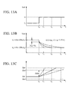
- Figs. 13A to 13C are diagrams explaining the relationship between the electrostatic capacitance of the electric double layer capacitor and the response characteristics of the reacting gas supply system.
- Fig. 14 is a diagram showing the reacting gas supply amount characteristics for obtaining the reacting gas supply amount as a function of the output current.
- Fig. 4 is a diagram showing a schematic diagram of an electric vehicle provided with a fuel cell power supply unit 10 according to one embodiment of the present invention.
- the fuel cell power supply unit 10 is installed in a vehicle and functions as a power supply for driving the vehicle.
- the fuel cell power supply unit 10 is a hybrid-type power supply unit comprised of a fuel cell 1 and an electric double layer capacitor (hereinafter, simply called a capacitor) 2 both of which are connected in parallel.
- Th fuel cell power supply unit 10 supplies power to a traction motor 3 and the power of the traction motor 3 supplied from the fuel cell power supply unit 10 is transmitted to driving wheels through a reduction or a transmission T/M (not shown).
- the traction motor 3 In the deceleration mode of the fuel cell vehicle provided with the fuel cell power supply unit 10 according to one embodiment of this invention, when the driving force is transmitted from the driving wheel to the traction motor 3, the traction motor 3 functions as a generator and generates regenerative braking power for recovering the kinetic energy of the vehicle as electrical energy.
- the traction motor 3 is a permanent magnet-type three phase alternating current synchronous motor which utilizes a permanent magnet for magnetic field and the traction motor 3 is driven by the three-phase alternating current.
- the fuel cell 1 is composed of a stack of a plurality of cells, each of which is formed by inserting a polymer electrolyte membrane formed by an ion exchange film and the like between an anode and a cathode, and the fuel cell 1 is provided with a hydrogen electrode to which hydrogen is supplied and an oxygen electrode to which air containing oxygen as an oxidizing agent is supplied.
- the power generation of the fuel cell 1 is carried out as follows. That is, hydrogen ions produced by a catalytic reaction at the anode are transmitted to the cathode through a polymer electrolyte membrane and the electrical power is generated by an electrochemical reaction taking place between hydrogen ions with oxygen at the cathode.
- the capacitor 2 used for the fuel cell power supply unit 10 is, for example, an electric double layer capacitor.
- a control device 4 is constituted as a logic circuit including a microcomputer as a main component and the control device 4 comprises a CPU, ROMs, RAMs, and input and output ports (components are not shown).
- the CPU executes prescribed calculation processes in accordance with predetermined control programs.
- the ROMs stored in advance control programs and control data which are required for carrying out a variety of calculation processes by the CPU, and the RAMs are used for reading and writing all types of data which are necessary for executing various calculation processes.
- the input and output ports receives signals detected by various sensors, such as a remaining charge monitoring device, and outputs signals to predetermined portions for controlling driving states of the fuel cell power supply unit 10 and every component of the fuel cell vehicle.
- the control device 4 calculates a target generation amount based on signals inputs as parameters such as an accelerator pedal opening signal concerning depression operation of the accelerator pedal by a driver, signals of the vehicle speed and a rotation speed of the motor, and signals of sensors associated with energy consumption of electrical auxiliary devices.
- the target generation amount obtained as described above is transmitted to the fuel cell power supply unit 10 as well as to the traction motor 3.
- the remaining charge of the capacitor 2 is calculated based on signals from sensors such as a voltage sensor or a current sensor (not shown), and the remaining charge of the capacitor is used as one of the parameters for controlling the fuel cell power supply unit 10.
- various components are used in addition to the above-described constituting elements such as an inverter for converting the direct current supplied from the fuel cell power supply unit 10 to three phase alternative current and supplying the three-phase alternating currents, sensors for detecting voltage, current, and temperatures of the fuel cell power supply unit 10, and switching elements for switching based on signals input from the control device 4. Explanations of these constituting elements will be described later.
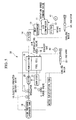
- Fig. 5 is a block diagram showing the structure of a fuel cell system 30 composed of the fuel cell 1 and the peripheral devices.
- an air compressor 11 connected to the oxygen electrode side of the fuel cell 1 supplies air not only to the oxygen electrode but also to the regulator 17 as a signal pressure.
- a rotation speed command value N is input from the control device 4 to the motor (not shown) which is used for driving the air compressor 11.
- the motor drives the air compressor 11 based on the rotation speed command value N and the air compressor thereby compresses externally introduced air for supplying to a heat exchanger 13.
- the compressed air is cooled by the heat exchanger 13 and dust is removed by a filter.
- Air after dust is removed, is supplied to a humidifier 15, and the humidified air supplied to the fuel cell 1 is used for the above-described electrochemical reaction. After this, air is exhausted from the fuel cell after passing through a pressure regulating valve 16 provided for regulating the pressure drop of the air to path through the fuel cell 1.
- a regulator 17 (called a proportional pressure regulator) regulates the pressure of hydrogen supplied from a high pressure hydrogen tank 18 to the fuel cell 1 based on the air pressure (pilot signal) supplied from the air supply side. As described above, the air pressure and the hydrogen pressure to be supplied from the air supply side and the hydrogen supply side are controlled by a regulator 17 so as to be balanced.
- the pressure of hydrogen supplied from the high pressure hydrogen tank 18 is high, the pressure of hydrogen is reduced by a regulator 17 after being firstly reduced by an electric-operated shutoff valve 19 and hydrogen after the pressure reduction is supplied to a humidifier 15 through an ejector 20. After humidifying by the humidifier 15, hydrogen is supplied to the fuel electrode of the fuel cell 1. After being used for the electrochemical reaction, hydrogen is discharged from the fuel cell 1 to a demister 21. The discharged gas supplied into the demister 21 is subjected to gas-liquid separation and hydrogen in the gas phase state is circulated to the supply side of hydrogen through an ejector 20 to be reused.
- a purge valve 22 is provided at the exhaust side of hydrogen for discharging water held in the fuel cell and the demister.
- the above-described electric-operated shutoff valve 19 also has a function to cutoff the hydrogen supply from the high pressure hydrogen tank 18.
- Water pumps 40 and 41 are used for circulating cooling water after being cooled by heat dissipation in radiators 23 and 24 in the auxiliary devices/control devices for controlling the temperature of the auxiliary devices/control devices below a predetermined temperature.
- the water pump 40 is provided for cooling the fuel cell 1, the auxiliary devices/control devices and for heating the fuel supply side, and the water pump 41 is provided for cooling the air supply devices.
- the auxiliary devices/control devices output a driving signal for the air regulator 16 and the electric power generation output of the fuel cell is controlled by opening or closing the air supply to the fuel cell 1 or by regulating the amount of air supply to the fuel cell 1.
- Fig. 6 is a diagram showing an equivalent circuit of the fuel cell power supply unit 10 according to one embodiment of the present invention.
- Vfc denotes a electromotive force of the fuel cell
- Rfc denotes an internal resistance of the fuel cell
- Ifc denotes a current flowing in the fuel cell.
- Vcap denotes a charge voltage
- Rcap denotes an internal resistance
- Icap denotes a capacitor current.
- Vout denotes an output voltage of the fuel cell power supply unit 10 and lout denotes a current flowing in the fuel cell power supply unit 10.
- the control device 4 When such a load current takes place, the control device 4 requires of the fuel cell power supply unit 10 to output power corresponding to the variation of electrical load, that is, an output corresponding to the load current I 2 .
- the output corresponding to the variation of electrical load is not generated until the control device 4 transmits a rotation speed command value to the motor for driving the air compressor as the auxiliary device, the rotation speed of the compressor increases, the reacting gas supply increases, and the electrochemical reaction takes place in the fuel cell 1.
- the capacitor 2 connected in parallel to the fuel cell 1 can supply a necessary amount of electric power to the traction motor 3 for responding to the variation of electrical load.
- Figs. 7A and 7B show a time dependent variation of the output voltage Vout (response characteristics) of the fuel cell power supply unit 10 when the load current lout varies stepwise from I 1 to I 2 .
- Fig. 7A shows the response characteristics of the output voltage
- Fi. 7B shows the response characteristics of the load current.
- the capacitor starts supplying the electric power corresponding to the variation of electrical load.
- the voltage drop immediately after the variation of electrical load is smaller when the internal resistance of the capacitor 2 is smaller.
- This oversupply amount is determined by the internal resistance and the capacitance of the capacitor which constitutes the fuel cell power supply unit 10, a prescribed width of the variation of electrical load, and characteristic values of the fuel cell 1 and the fuel cell system 30.
- Fig. 1 As shown by the line A which shows the current-voltage characteristic line of the fuel cell 1, a higher output voltage is obtained when the output current is low and the output voltage decreases as the output voltage increases. When the output voltage and the output current are below the line A, the fuel cell is assumed to be in the gas shortage state.
- the line B1 in Fig. 1 shows a current-voltage characteristic line of the fuel cell power supply unit 10 when the maximum amount of the reacting gas is set and supplied to the fuel cell 1 prior to the variation of electrical load.
- the excess supply amount of the reacting gas to the fuel cell is set at an amount which is capable of outputting a current I LI1 (I 1 ⁇ I LI1 ⁇ I 2 ), that is, when the supply amount of the reacting gas makes the fuel cell reach an equilibrium output current I LI1 .
- This supply amount of the reacting gas corresponds to the oversupply amount capable of outputting the current of I LI1 - I 1 .
- the capacitor 2 assists the output power as the fuel cell power supply unit 10. That is, the output power of the fuel cell power supply unit 10 is dependent on the output of the capacitor until the fuel cell 1 can supply the output power corresponding to the variation of electrical load, which corresponds to the transition time of the fuel cell for responding to the variation of electrical load.
- the output voltage of the fuel cell power supply unit 10 at an output current I 2 immediately after the variation of electrical load can be obtained as V d1 from the line D1, and the voltage drop ⁇ V of the fuel cell power supply unit 10 when the variation of electrical load is applied in a stepwise manner can be obtained as the voltage by subtracting the output voltage V d1 at I 2 from the output voltage V 1 at I 1 .
- the fuel cell 1 Since it is possible for the fuel cell 1 to output an output voltage which corresponds to an output current, equilibrated with the amount of the reacting gas supplied before the variation of electrical load, the output voltage is obtained as V LI1 from the line A.
- an allowable voltage drop ⁇ V' for the fuel cell 1 immediately after the variation of electrical load is obtained by subtracting the output voltage V LI1 at I LI1 from the output voltage V 1 at I 1 , as shown in Fig. 1.
- the allowable voltage drop ⁇ V' which is estimated from the amount of reacting gas supplied to the fuel cell 1 before the variation of electrical load, is larger than the voltage drop ⁇ V immediately after the variation of electrical load, it is possible to prevent the fuel cell from entering into the gas shortage state.
- the line A in Fig. 2 is the same current-voltage characteristic line of the fuel cell 1 as that shown in Fig. 1.
- the line B2 in Fig. 2 shows a current-voltage characteristic curve of the fuel cell power supply unit 10 when the maximum amount of the reacting gas is set and is supplied to the fuel cell 1 prior to the variation of electrical load. As shown, a gradient of the current-voltage characteristic line B2 is more gentle than that of the characteristic line B1, since the internal resistance Rcap of the capacitor 2 is equal to the internal resistance Rfc of the fuel cell.
- a response characteristics of the fuel cell power supply unit 10 is described below when the load current is varied stepwise from I 1 to I 2 .
- the excess supply amount of the reacting gas to the fuel cell is set at an amount which is capable of outputting a current I LI2 (I 1 ⁇ I LI2 ⁇ I 2 ), that is, when the supply amount of the reacting gas makes the fuel cell reach an equilibrium output current I LI2 , the output power of the fuel cell is not sufficient so as to respond to the variation of electrical load so that the capacitor 2 assists the output power as the fuel cell power supply unit 10.
- the excess supply amount corresponds to the amount of the reacting gas which enable to output the current I LI2 -I 1 .
- the current-voltage characteristics of the fuel cell power supply unit 10 is modified to the synthetic current-voltage characteristics composed of both characteristics of the fuel cell 1 and capacitor 2, which is shown by line B2 in Fig. 2.
- the output voltage of the fuel cell power supply unit 10 is represented by the current-voltage characteristics of the capacitor, that is, as shown by line D2 in Fig. 2.
- the gradient of the line D2 is identical with that of the current-voltage characteristic line A.
- the output voltage of the fuel cell power supply unit 10 at a current I 2 is obtained as V d2 from the line D2. Therefore, the voltage drop ⁇ V due to the internal resistance Rcap of the capacitor 2 when the load current varies stepwise from I 1 to I 2 can be obtained as shown in Fig. 2, as explained similarly for Fig. 1.
- the output voltage corresponding to an output current which is in equilibrium with the amount of reacting gas supplied to the fuel cell 1 is obtained as V LI2 from the line A, and it is estimated that the fuel cell 1 can output the output voltage to the extent of V LI2 .
- the allowable output voltage variation ⁇ V' for the fuel cell 1 when the load current varies from I 1 to I 2 is obtained as shown in Fig. 2.
- the line A in Fig 3 shows a current-voltage characteristic line of the fuel cell, similarly to Fig. 1.
- the line B3 in Fig. 3 shows a current-voltage characteristic line of the fuel cell power supply unit 10 when the maximum amount of the reacting gas is set and is supplied to the fuel cell 1 prior to the variation of electrical load. Since the internal resistance Rcap of the capacitor 2 is lower than the internal resistance Rfc of the fuel cell 1, the gradient of the current-voltage characteristic line B3 becomes more gentle that that of the line B2.
- the response characteristics of the fuel cell power supply unit 10 will be described when the load current varies stepwise from I 1 to I 2 .
- the excess supply amount to the fuel cell 1 is set to a value capable of outputting the output current I LI3 (I 1 ⁇ I LI3 ⁇ I 2 ), that is, when the amount of the reacting gas is set to an amount capable of outputting an equilibrated current I LI3 , since the output power from the fuel cell 1 is not sufficient in a region higher than I LI3 , similarly in the case of Fig. 1, the output power is assisted by the capacitor 2.
- the excess supply amount of the reacting gas corresponds to that for outputting a power of I LI3 - I 1 .
- the current-voltage characteristics of the fuel cell power supply unit 10 is thereby governed by the synthetic current-voltage characteristics of both fuel cell 1 and capacitor 2, and when the current is higher than I LI3 , the current-voltage characteristics of the fuel cell power supply unit 10 is governed by that of the capacitor 2, shown by line D3.
- the output voltage at a current I 2 of the fuel cell power supply unit 10 is obtained as V d3 from the line D3.
- the load current varies stepwise from I 1 to I 2
- the voltage drop ⁇ V due to the internal resistance Rcap of the capacitor can be obtained as shown in Fig. 3, similarly shown in Fig. 1.
- the fuel cell 1 is capable of outputting the power until the output voltage of V LI3 .
- the allowable output variation ⁇ V' for the fuel cell 1 for the variation of electrical load from I 1 to I 2 is obtained as the value as shown ⁇ V' in Fig. 3.
- the solid line shown in Fig. 10A show a current-voltage characteristics of a fuel cell 1.
- the dotted line of Fig. 10A shows synthetic current-voltage characteristics and the starting point (the equilibrium point U) of the characteristics lines is an equilibrium point where the fuel cell 1 and the capacitor 2 are substantially coupled.
- the solid line in Fig. 10B represent the relationship between the output current and the supply amount of the reacting gas to the fuel cell 1. As shown in Fig. 10B, the output current increases as the amount of the reacting gas supplied to the fuel cell 1 increases.
- the dotted line in Fig. 10B shows an output current dependency of the amount of the reacting gas including the excess amount to be supplied to the fuel cell (hereinafter, simply called the reacting gas supply amount characteristics) for preventing the fuel cell from entering into the gas shortage state due to the voltage drop generated by the current variation of electrical load.
- the reacting gas supply amount characteristics will be described later.
- the solid line in Fig. 10B shows a minimum necessary amount of the reacting gas for obtaining the current-voltage characteristics of the fuel cell 1 shown by the solid line in Fig. 10A.
- the equilibrium reacting gas supply amount Based on the relationship between the current-voltage characteristics and the amount of the reacting gas supplied to the fuel cell 1, the amount of the reacting gas supplied to the fuel cell 1 when the fuel cell is in the equilibrium state is called the equilibrium reacting gas supply amount.
- the output current Ifc 2 ' of the fuel cell 1 corresponding to the synthetic output voltage V 2 is obtained from the current-voltage characteristics of the fuel cell 1, and the equilibrium reacting gas supply amount Qa 2 corresponding to the output current Ifc 2 ' is obtained from the diagram of the reacting gas supply amount characteristics shown in Fig. 10B.
- the equilibrium reacting gas supply amount Qa 2 is defined as the reacting gas supply amount corresponding to the output current I 2 .
- Fig. 10B shows the reacting gas supply amount characteristics with an addition of the excess amount obtained by the method described above.
- the current-voltage characteristics of the fuel cell 1 shown in Fig. 10A is a part of the characteristic curve for simply explaining the equilibrium reacting gas supply amount.
- the practical characteristic curve is represented by the solid line shown in Fig. 11A.
- the practical current-voltage characteristics of the fuel cell 1 is not represented by a linear line, but is represented by a solid curve as shown in Fig. 11A.
- the dotted line in Fig. 11A shows synthetic current-voltage characteristic curves of the fuel cell 1 and the capacitor 2 illustrated derived from optional equilibrium origins.
- the equilibrium reacting gas supply amount corresponding to the above-described characteristic curve of the fuel cell is expressed by the solid line in Fig. 11B.
- the actual reacting gas amount supplied to the fuel cell 1 is shown by the dotted line in Fig. 11B.
- the gradient of the synthetic current-voltage characteristics of the fuel cell 1 and the capacitor 2 increases as the internal resistance Rcap of the capacitor 2 increases.
- the reacting gas supply amount characteristics corresponding to each current-voltage characteristics indicates that the excess supply amount must set to a higher level as the internal resistance Rcap of the capacitor 2 is larger.
- this may be accomplished by selecting a capacitor 2 whose internal resistance is as low as possible.
- the fuel supply unit comprises the fuel cell 1 and the peripheral devices such as air compressor 11.
- the peripheral devices practically include the compressor 12, heat exchanger 13, high pressure hydrogen tank 18, electric-operated shutoff valve 19, regulator 17, ejector 20, demsiter 21, and humidifier 15.
- the time to reach the equilibrium state is longer when the electrostatic capacitance C of the capacitor 2 is larger.
- Fig. 13C shows the time dependent variation of the reacting gas supply amount.
- the solid, dotted, and chain lines in Fig. 13C corresponds to respective characteristic curves shown in Fig. 13B.
- the reacting gas supply amounts Qa 1 ', Qa 1 , Qa 2 ', Qa 2 in Fig. 13C represent, respectively, the equilibrium reacting gas amount Qa 1 'at the load current I 1 before the variation of electrical load, the reacting gas supply amount Qa 1 including the excess supply amount at the load current I 1 , the equilibrium reacting gas supply amount Qa 2 ' at the load current I 2 after the variation of electrical load, and the reacting gas supply amount Qa 2 including the excess supply amount at the load current I 2 , as shown in Fig. 14.
- the response time of the variation of the reacting gas supply amount to the fuel cell 1 from the reacting gas supply amount Qa 1 before the variation of electrical load to the equilibrium reacting gas supply amount Qa 2 ' is required to be short. This is, if the capacitor 2 cannot supply the necessary amount of output corresponding to the current I 2 after the variation of electrical load within a period of time (the output assistance operation period) in which the capacitance can assist the output corresponding to the variation of electrical load, the output from the fuel cell 1 and the capacitance 2 is deficient, which results in causing the gas shortage state occuring in the fuel cell 1.
- Fig. 9 is a diagram showing the response characteristics of the fuel cell power supply unit 10 during the variation of electrical load.
- the require torque Ap varies from I 1 to I 2 from time T1 to time T2 according to the variation of the depression amount of the accelerator pedal, when a driver depresses the accelerator pedal.
- the motor required current Imot varies from I 1 to I 2 accompanying a small delayed time.
- Fig. 9 illustrates a relationship between the amount of reacting gas supplied by the compressor 11 and the equilibrium rotation speed to the reacting gas amount.
- the rotation speed which is in equilibrium with the reacting gas supply amount at the time T0 before the variation of electrical load is Nm 1 .
- the rotation speed starts to vary at time T 1 after a certain time delay, and reaches a rotation speed Nm 2 corresponding to the output current I 2 at time T3 and the rotation speed further increases until it reaches an equilibrium rotation speed corresponding to a value including an excess reacting gas supply amount in addition to the rotation number Nm 2 after the variation of electrical load.
- the output current of the fuel cell 1 starts increasing after the variation of electrical load with the increasing amount of the reacting gas, and at time T4, the output current reaches an equilibrium current I 2 , the fuel cell outputs a higher current than I 2 for a while, and thereafter the output current converges to the current I 2 .
- the capacitor 2 discharges electric power for assisting the output power while the output power of the fuel cell is shortage.
- the capacitor 2 starts discharging the power at time T1 and the output current of the capacitor 2 varies along the variation of the output current of the fuel cell 1 until the output current of the fuel cell 1 reaches the equilibrium state.
- the synthetic output current Iall of the output currents of the fuel cell 1 and the capacitor 2 varies so as to satisfy the required torque Ap.
- the synthetic output voltage Vout of the fuel cell 1 and the capacitor 2 starts decreasing from time T1 and reaches an equilibrium voltage after the variation of electrical load at time T5.
- the amount of the reacting gas supplied from the reacting gas supply unit of the fuel cell 1 varies from the supply amount of the reacting gas before the variation of electrical load at time T0, that is, the supply amount equilibrated with the rotation speed Nm 1 of the compressor 11 to a supply amount (for example, supply amount corresponding to the rotation speed Nm 2 ) required to output at least an output current (for example, I 2 ) after the variation of electrical load at time T3.
- the response time of the reacting gas supply unit is T3 - T0.
- the above-described response time corresponds the changing time of the synthetic output voltage Vout of the fuel cell 1 and the capacitor 2 from a equilibrium voltage at T0 reaches the output voltage V 2 corresponding to an equilibrium current I 2 after the variation of electrical load.
- the excess amount of the reacting gas to be supplied to the fuel cell 1 and the capacitor characteristics is determined such that the output assistance operation period of the capacitor 2, that is, the time period of T5 - T0, is longer than the above-described time period of T3 - T0.
- the amount of the reacting gas to be supplied to the fuel cell 1 from the reacting gas supply unit is set by the control device 4 based on a target generation amount.
- This target generation amount is calculated by the control device 4 based on various input signals indicating the driving state of the vehicle such as the accelerator pedal opening, the vehicle speed, and power consumption of auxiliary devices (see Fig. 4). Accordingly, if is necessary to calculate the target generation amount including the excess supply amount in order to supply the reacting gas amount including the excess reacting gas amount.
- the control device 4 sets a target generation quantity, as shown in Fig. 8B, including an excess generation quantity. If the load output varies stepwise at time t 0 and the voltage drop takes place, it is thereby possible to prevent gas shortage of the fuel cell 1 by supplying an excess amount of the reacting gas in advance for filling the shortage amount of the reacting gas by the voltage drop.
- the control device calculates the target generation command value at predetermined intervals and a width of the variation of electrical load is obtained by comparing two target generation command quantities.
- the width of the variation of electrical load is obtained by comparing two command values, for example, between the newest target generation command value and the previous target generation command value, and the newest generation command value is updated such that the width of the variation of electrical load used for setting the excess amount becomes lower than the above-described predetermined width of the variation of electrical load.
- the newest target generation quantity is updated such that the width of the variation of electrical load becomes less than ⁇ I.
- the reasons for setting such correction is that if the width of the variation of electrical load exceeds the predetermined width of the variation of electrical load I the fuel cell 1 can not output a required amount of output power, which results in entering into the gas shortage state in the fuel cell.
- the control device always set the target generation quantity so as to satisfy the above conditions, and so as not to require the fuel cell 1 to output the power exceeding the target supply amount, and the fuel cell 1 is protected from being in the gas shortage state.
- the fuel cell 1 substantially directly connected to the capacitor 2 is used for the fuel cell power supply unit according to one embodiment of the present invention.
- a current limiting device (not shown) is provided between the fuel cell 1 and the capacitor 2.
- the current limiting device is described with reference to Fig. 1
- the electric power is mainly supplied by the capacitor 2. Therefore, the remaining charge of the capacitor rapidly decreases and the potential of the capacitor becomes relatively low when compared with the potential of the fuel cell. If the capacitor 2 in this state is substantially directly connected to the fuel cell 1, a large current flows from the fuel cell 1 to the capacitor 2 and the potential of the fuel cell also decreases rapidly.
- the fuel cell 1 is directed into the state where the amount of the reacting gas becomes shortage, that is, the gas shortage state. Accordingly, while there is a large potential gap between the fuel cell 1 and the capacitor 2, it is necessary to limit the output current of the fuel cell 1 for preventing the fuel cell 1 from the gas shortage state.
- the output current of the fuel cell 1 is controlled by the current limiting device (not shown), while charging the capacitor 2. Thereafter, when the potential difference between the fuel cell and the capacitor 2 becomes lower than a predetermined potential difference, the control of the output current from the fuel cell is stopped and the fuel cell 1 and the capacitor 2 are used in a directly connected state.
- a current limiting device constituted by a device such as a chopper-type DC/DC converter, is provided between the fuel cell 1 and the capacitor 2, similarly to the conventional case.
- a switching device provided in the current limiting device thereby limits the output current from the fuel cell 1 by its ON/OFF operation.
- the current limiting device stops its operation, the switching device is preserved at the ON state, and the fuel cell 1 and the capacitor enter in the directly connected state.
- the present unit practically includes the current limiting device between the fuel cell1 and the capacitor 2, the current limiting device does not execute the switching operation when the power supply unit is used in the actual driving operations as described above.
- the fuel cell power supply unit operates as if the current limiting device does not exists.
- the present invention provides a fuel cell power supply unit with a high power efficiency by using the fuel cell and the capacitor connected in parallel.
- the fuel cell power supply unit of the present invention is used by firstly obtaining the voltage of the fuel cell after the variation of electrical load based on the synthetic current-voltage characteristics of the fuel cell and the capacitor starting from an equilibrium point of the current-voltage characteristics of the fuel cell, secondly obtaining the current corresponding to the above-obtained voltage based on the current-voltage characteristics of the fuel cell, thirdly obtaining the supply amount of the reacting gas corresponding to the current, and supplying the reacting gas for outputting the power to the fuel cell in an amount which includes an excess gas amount in addition to the equilibrium reacting gas supply amount, so that the present invention realizes a fuel cell power supply unit having a high power output efficiency while protecting the fuel cell from entering into the gas shortage state.
- the fuel cell power supply unit of the present invention stops the operation of the current limiting device when the potential difference between the fuel cell and the capacitor is rendered to be lower than the predetermined difference and the fuel cell supply unit is used at the state wherein the fuel cell and the capacitor are substantially directly connected.
- the present invention is capable of providing an excess supply amount, which is the minimum necessary amount of the reacting gas to be supplied to the fuel cell for coping with a voltage drop, so that it is possible to avoid supplying useless reacting gas and to supply the reacting gas efficiently.
- the reacting gas supply amount is determined based on the current-voltage characteristics of the fuel cell, the current-voltage characteristic of the capacitor, and the reacting gas supply amount at the equilibrium state corresponding to the current-voltage characteristics of the fuel cell, so that the reacting gas supply amount for coping with the voltage drop can be obtained accurately, which makes it possible to improve performance of the fuel cell power supply unit.
- the reacting gas supply amount to the fuel cell at the time of variation of electrical load is determined dependent on the internal resistance of the fuel cell.
- the detailed determination of the reacting gas supply amount by the internal resistance of the fuel cell makes it possible to supply the optimum amount of the reacting gas while preventing the gas shortage state of the fuel cell, which results in improving the performance of the fuel cell power supply unit.
- the reacting gas supply amount is determined based on the internal resistance of the electric double layer capacitor because the current-voltage characteristics of the capacitor is dependent on the internal resistance and the electrostatic capacitance of the capacitor.
- the detailed determination of the reacting gas supply amount by the internal resistance of the capacitor makes it possible to supply the optimum amount of the reacting gas while preventing the gas shortage state of the fuel cell, which results in improving the performance of the fuel cell power supply unit.
- the reacting gas amount supplied to the fuel cell is determined such that the response time reaching from a reacting gas supply amount at an output state to the reacting gas supply amount after the variation of electrical load is lower than the output assisting time by the capacitor, the reacting gas is supplied efficiently to the fuel cell while preventing the fuel cell from being gas shortage, and the present invention has realized a fuel cell power supply unit which has a high power output efficiency.
- the response time of the reacting gas supply system is determined so as to be lower than the output assisting time by the capacitor, the reacting gas is supplied efficiently to the fuel cell while preventing the fuel cell from being gas shortage, and an effect is obtained that a fuel cell power supply unit has a high power output efficiency.
- the capacitance of the capacitor is determined such that the response time of the reacting gas supply system is lower than the output assisting time by the capacitor, the reacting gas is supplied efficiently to the fuel cell while preventing the fuel cell from being gas shortage, and an effect is obtained that a fuel cell power supply unit has a high power output efficiency.
- a fuel cell power supply unit whose reacting gas supply amount to be supplied to the fuel cell is determined based on a target generation command value, while calculating the target output command value for driving the motor and the target generation command value for the fuel cell at a predetermined interval based on the input signals indicating the driving state of the vehicle, since the width of the variation of electrical load (the difference between two generation command values) obtained based on two sequentially obtained target generation command quantities (the newest generation command value and the previous generation command value) is controlled so as to be lower than the predetermined width of the variation of electrical load (for example, the width of the variation of electrical load ⁇ I).
- a current limiting device for example, as shown in the embodiment, a current limiting device comprising a chopper-type DC/DC converter
- functions for charging the capacitor when the current limiting device is a chopper-type DC/DC converter, the switching device in the converter performs switching operations
- the fuel cell and the capacitor are rendered to the directly connected state when the potential difference between the fuel cell and the capacitor is reduced to be lower than a predetermined potential difference (for example, the fuel cell does not fall into the gas shortage state).
- the fuel cell and the capacitor can be substantially directly connected as described above, it is possible to avoid the power loss by the switching operation in the current limiting device and it is also possible to supply the power to the load effectively.
- the present invention provides a highly efficient fuel cell power supply unit, which is constructed by directly connecting a fuel cell with a capacitor.
- a control device of the unit calculates the output voltage V 2 of the fuel cell after the variation of electrical load based on the synthetic current-voltage characteristics of the fuel cell and the capacitor and the predetermined width of the variation of electrical load ⁇ I, calculates the corresponding current Ifc 2 ', and then calculates the equilibrium reacting gas supply amount Qa 1 , and supplies an excess amount of the reacting gas exceeding Qa 1 before the variation of electrical load.
Abstract
Description
- The present invention relates to a power supply unit, which is constituted by directly connecting a fuel cell with an electric double layer capacitor.
- Conventionally, a hybrid-type power supply unit, constituted by combining an electrochemical fuel cell (hereinafter, called a "fuel cell") and an electric double layer capacitor (hereinafter, called a "capacitor"), has been known as a hybrid power source for driving an electric vehicle.
- The hybrid-type power supply unit is capable of supplying power for a traction motor of an electric vehicle in a stable manner by compensating for the power deficiency of the fuel cell caused by the slow response of the fuel cell at the time of transitional variation of the load with energy stored in the capacitor.
- As described above, since the response of the fuel cell for the transitional variation of the load is slow, the fuel cell, even combined with a capacitor, is unable to supply sufficient energy for the sudden variation of the load, which results in entering into, what is called, the "gas-shortage state ".
- Accordingly, as a conventional measure to prevent a power deficiency, a DC/DC converter, provided between a fuel cell and a capacitor, is provided in order to control the output of the fuel cell. The DC/DC converter is used for controlling the output of the fuel cell so as not to exceed the output corresponding to an amount of reacting gas (including air and fuel gas) supplied to the fuel cell.
- However, the DC/DC converter as an output control device controls the output of the fuel cell by a high speed switching (ON/OFF operation) of the switching element provided in the control device, and a problem arises in that the power loss due to the high speed switching operation becomes inevitably high.
- In addition, in order to cope with a high output current of the fuel cell, the above output control device is designed to have a high current capacity, which causes a problem in that the control device must be large occupying a large amount of space in an electric vehicle.
- The present invention was made to solve the above problems, and the present invention provides a power supply unit which exhibits a very high power efficiency by using a fuel cell by substantially directly connecting with a capacitor.
- The present invention provides a fuel cell power supply unit (fuel cell power supply unit 10) comprising a fuel cell (for example, fuel cell 1) and a capacitor (capacitor 2), both of which are connected in parallel, the fuel cell power supply unit uses an excessive amount of a reacting gas supplied to the fuel cell at an output state (the output current Ifc = I1 in Fig. 10A) by determining a voltage (V2 in Fig. 10B) of the fuel cell after the variation of electrical load based on a synthetic output characteristics (the characteristic line shown by the dotted line in Fig. 10A) of the fuel cell and the capacitor, originated from a equilibrium point (equilibrium point U in Fig. 10A) on a current-voltage characteristics (characteristic line shown by the solid line in Fig. 10A) of the fuel cell at a predetermined output state and a predetermined width of a variation of electrical load (ΔI shown in Fig. 10A), determining a current (Ifc2' in Fig. 10A) corresponding to the voltage, obtaining a reacting gas supply amount (Qa1 in Fig. 10B) corresponding to the current, and supplying the reacting gas at an amount which exceeds the equilibrium reacting gas supply amount (the output current Ifc = I1) before the variation of electrical load.
- According to the above constitution, since an increased amount of the reacting gas is supplied to the fuel cell in advance of the variation of electrical load, it is possible to prevent the fuel cell from entering into a gas-shortage state.
- The above setting method makes it possible to obtain an excess supply amount which is the minimum necessary amount to be supplied to the fuel cell before the variation of electrical load, which avoids supplying excess gas and to provides efficient supply of the reacting gas.
- In the above fuel cell power supply unit, the reacting gas amount supplied to the fuel cell at the output state is determined based on the current-voltage characteristics of said fuel cell (current-voltage characteristic lines shown by solid lines in Figs. 10A and 11A), the current-voltage characteristics of the capacitor (one element for obtaining the synthetic current-voltage characteristics shown by the dotted line in Fig. 10A), and the equilibrium reacting gas supply amount characteristics (reacting gas supply amount characteristic curve at the equilibrium state shown by the solid line in Fig. 10B) corresponding to the current-voltage characteristics of the fuel cell.
- The excess amount of the reacting gas supplied to the fuel cell at the equilibrium output state, the minimum necessary amount of the reacting gas supply amount after the variation of electrical load, can be accurately obtained.
- In the above fuel cell power supply unit, the current-voltage characteristics of the fuel cell depend on an internal resistance of the fuel cell or an average internal resistance of the fuel cell within a predetermined output current range.
- Since the current-voltage characteristics of the fuel cell depends on the internal resistance of the fuel cell, the necessary amount of the reacting gas at a predetermined output state differs by the internal resistance of the fuel cell. The accurate setting of the reacting gas supply amount based on the properties of the fuel cell enables avoiding the gas shortage state of the fuel cell and enables supplying an optimum amount of the reacting gas.
- In the above fuel cell power supply unit, the current-voltage characteristics of the electric double layer capacitor depends on the internal resistance of the electric double layer capacitor.
- Since the current-voltage characteristics of the capacitor depends on the internal resistance of the capacitor, the necessary amount of the reacting gas at a predetermined output state differs by the internal resistance of the capacitor. The accurate setting of the reacting gas supply amount based on the properties of the capacitor enables avoiding the gas-shortage state of the fuel cell and enables supplying an optimum amount of the reacting gas.
- In the above fuel cell power supply unit, the reacting gas amount supplied from the reacting gas supply system (the
fuel cell 1 and peripheral auxiliary electric machines such as thecompressor 11,heat exchanger 13, high-pressure hydrogen tank 18, electric-operatedshutoff valve 19, aregulator 17,ejector 20,demister 21, and a humidifier 15) to the fuel cell is determined such that the response time (the period from T0 to T3 in Fig. 9) reaching from the reacting gas amount at the predetermined output state (a reacting gas supply amount equilibrated with the rotation speed Nm1 of the compressor 11) to the equilibrium reacting gas amount after the variation of electrical load (a reacting gas supply amount equilibrated with the rotation speed Nm2 shown in Fig. 9) is shorter than the output assistance operation period (the period from T0 to T5 in Fig. 9) by the electric double layer capacitor. As shown above, since the minimum necessary amount of the reacting gas is supplied to the fuel cell during the output assisting operation time by the capacitor, the gas shortage state of the fuel cell can be eliminated. - In the above fuel cell power supply unit, the response time (the pump response characteristics COMP shown in Fig. 9) of said reacting gas supply system is set below the output assistance period of the electric double layer capacitor.
- Accordingly, the response time characteristics of the reacting gas supply system is determined as described above, and the output of the fuel cell can be converted into the equilibrium state after the variation of electrical load within the output assisting operation period by the capacitor.
- In the above fuel cell power supply unit, a capacitance of the electric double layer capacitor is determined such that the response time of said reacting gas supply system is set below the output assistance period by the output assistance operation period of the electric double layer capacitor.
- By determining the capacitance of the capacitor as described above, the minimum necessary amount of the reacting gas is supplied for outputting the output power after the variation of electrical load, and the fuel cell can be prevented from entering the gas- shortage state.
- In a fuel cell power supply unit, whose reacting gas supply amount to be supplied to the fuel cell is determined based on a target generation command value, while calculating the target output command value for driving the motor and the target generation command value for the fuel cell at a predetermined interval based on the input signals indicating the driving state of the vehicle, since a width of the variation of electrical load (the difference between two generation command values) obtained based on two sequentially obtained target generation command quantities (the newest generation command value and the previous generation command value) is controlled so as to be lower than the predetermined variation of electrical load width (for example, the variation of electrical load width ΔI).
- Thus, it is possible to prevent the fuel cell from entering the gas-shortage state by controlling so as not to require excessive output power which will resulted in the shortage state of the reacting gas for the fuel cell.
- According to the fuel cell power supply unit of the present invention, a current limiting device (for example, as shown in the embodiment a current limiting device comprising a chopper-type DC/DC converter) provided between the fuel cell and the capacitor functions for charging the capacitor (when the current limiting device is a chopper-type DC/DC converter, the switching device in the converter works switching operations) at the time of starting the vehicle, whereas the fuel cell and the capacitor are varied to a directly connected state when the potential difference between the fuel cell and the capacitor is reduced to be lower than a predetermined potential difference (for example, the fuel cell does not enter into the gas-shortage state).
- Since the fuel cell and the capacitor can be substantially directly connected as described above, it is possible to avoid power loss by the switching operation in the current limiting device, and it is also possible to supply the power to the load effectively.
- Fig. 1 is a diagram showing a example of the current-voltage characteristics of a fuel cell according to one embodiment of the present invention.
- Fig. 2 is a diagram showing another example of the current-voltage characteristics of a fuel cell according to one embodiment of the present invention.
- Fig. 3 is a diagram showing a schematic diagram of an electric vehicle which is provided with a fuel cell power supply unit according to one embodiment of the present invention.
- Fig. 4 is a diagram showing a schematic diagram of an electric vehicle provided with a fuel cell power supply unit according to one embodiment of the present invention.
- Fig. 5 is a diagram showing the fuel cell according to one embodiment and its peripheral devices.
- Fig. 6 is a diagram showing an equivalent circuit of the fuel cell power supply unit according to one embodiment of the present invention.
- Figs. 7A and 7B are diagrams showing the voltage response characteristics and current response characteristics of the fuel cell power supply unit according to one embodiment of the present invention.
- Fig. 8 is a diagram showing various output characteristics of the fuel cell power supply unit according to one embodiment of the present invention.
- Fig. 9 is a diagram showing various response characteristics of the fuel cell power supply unit according to one embodiment of the present invention.
- Figs. 10A and 10B show portions of various characteristics curves explaining method of setting the excess supplying amount.
- Figs. 11A and 11B are diagrams showing the current-voltage characteristics of the fuel cell and relationship between the supply amount of the reacting gas and the current-voltage characteristics of the fuel cell.
- Figs. 12A and 12B are diagrams showing the relationship between the internal resistance of the electric double layer capacitor and the supply amount of the reacting gas.
- Figs. 13A to 13C are diagrams explaining the relationship between the electrostatic capacitance of the electric double layer capacitor and the response characteristics of the reacting gas supply system.
- Fig. 14 is a diagram showing the reacting gas supply amount characteristics for obtaining the reacting gas supply amount as a function of the output current.
- Hereinafter, one embodiment of the present invention will be explained with reference to the drawings.
- Fig. 4 is a diagram showing a schematic diagram of an electric vehicle provided with a fuel cell
power supply unit 10 according to one embodiment of the present invention. - The fuel cell
power supply unit 10 according to one embodiment of the present invention is installed in a vehicle and functions as a power supply for driving the vehicle. The fuel cellpower supply unit 10 is a hybrid-type power supply unit comprised of afuel cell 1 and an electric double layer capacitor (hereinafter, simply called a capacitor) 2 both of which are connected in parallel. Th fuel cellpower supply unit 10 supplies power to atraction motor 3 and the power of thetraction motor 3 supplied from the fuel cellpower supply unit 10 is transmitted to driving wheels through a reduction or a transmission T/M (not shown). - In the deceleration mode of the fuel cell vehicle provided with the fuel cell
power supply unit 10 according to one embodiment of this invention, when the driving force is transmitted from the driving wheel to thetraction motor 3, thetraction motor 3 functions as a generator and generates regenerative braking power for recovering the kinetic energy of the vehicle as electrical energy. Thetraction motor 3 is a permanent magnet-type three phase alternating current synchronous motor which utilizes a permanent magnet for magnetic field and thetraction motor 3 is driven by the three-phase alternating current. - The
fuel cell 1 is composed of a stack of a plurality of cells, each of which is formed by inserting a polymer electrolyte membrane formed by an ion exchange film and the like between an anode and a cathode, and thefuel cell 1 is provided with a hydrogen electrode to which hydrogen is supplied and an oxygen electrode to which air containing oxygen as an oxidizing agent is supplied. The power generation of thefuel cell 1 is carried out as follows. That is, hydrogen ions produced by a catalytic reaction at the anode are transmitted to the cathode through a polymer electrolyte membrane and the electrical power is generated by an electrochemical reaction taking place between hydrogen ions with oxygen at the cathode. - The
capacitor 2 used for the fuel cellpower supply unit 10 is, for example, an electric double layer capacitor. - A control device 4 is constituted as a logic circuit including a microcomputer as a main component and the control device 4 comprises a CPU, ROMs, RAMs, and input and output ports (components are not shown). The CPU executes prescribed calculation processes in accordance with predetermined control programs. The ROMs stored in advance control programs and control data which are required for carrying out a variety of calculation processes by the CPU, and the RAMs are used for reading and writing all types of data which are necessary for executing various calculation processes. The input and output ports receives signals detected by various sensors, such as a remaining charge monitoring device, and outputs signals to predetermined portions for controlling driving states of the fuel cell
power supply unit 10 and every component of the fuel cell vehicle. - For example, the control device 4 calculates a target generation amount based on signals inputs as parameters such as an accelerator pedal opening signal concerning depression operation of the accelerator pedal by a driver, signals of the vehicle speed and a rotation speed of the motor, and signals of sensors associated with energy consumption of electrical auxiliary devices. The target generation amount obtained as described above is transmitted to the fuel cell
power supply unit 10 as well as to thetraction motor 3. The remaining charge of thecapacitor 2 is calculated based on signals from sensors such as a voltage sensor or a current sensor (not shown), and the remaining charge of the capacitor is used as one of the parameters for controlling the fuel cellpower supply unit 10. - In order to drive the fuel cell
power supply unit 10 according to the one embodiment of the present invention, various components are used in addition to the above-described constituting elements such as an inverter for converting the direct current supplied from the fuel cellpower supply unit 10 to three phase alternative current and supplying the three-phase alternating currents, sensors for detecting voltage, current, and temperatures of the fuel cellpower supply unit 10, and switching elements for switching based on signals input from the control device 4. Explanations of these constituting elements will be described later. - Although not shown in the block diagram of Fig. 4, the
fuel cell 1 is required to provide peripheral devices in addition to the fuel cell body composed of the cell stack structure for executing power generation by thefuel cell 1. Fig. 5 is a block diagram showing the structure of afuel cell system 30 composed of thefuel cell 1 and the peripheral devices. - As shown in Fig. 5, an
air compressor 11 connected to the oxygen electrode side of thefuel cell 1 supplies air not only to the oxygen electrode but also to theregulator 17 as a signal pressure. Thus, a rotation speed command value N is input from the control device 4 to the motor (not shown) which is used for driving theair compressor 11. The motor drives theair compressor 11 based on the rotation speed command value N and the air compressor thereby compresses externally introduced air for supplying to aheat exchanger 13. The compressed air is cooled by theheat exchanger 13 and dust is removed by a filter. - Air, after dust is removed, is supplied to a
humidifier 15, and the humidified air supplied to thefuel cell 1 is used for the above-described electrochemical reaction. After this, air is exhausted from the fuel cell after passing through apressure regulating valve 16 provided for regulating the pressure drop of the air to path through thefuel cell 1. - A regulator 17 (called a proportional pressure regulator) regulates the pressure of hydrogen supplied from a high
pressure hydrogen tank 18 to thefuel cell 1 based on the air pressure (pilot signal) supplied from the air supply side. As described above, the air pressure and the hydrogen pressure to be supplied from the air supply side and the hydrogen supply side are controlled by aregulator 17 so as to be balanced. - Since the pressure of hydrogen supplied from the high
pressure hydrogen tank 18 is high, the pressure of hydrogen is reduced by aregulator 17 after being firstly reduced by an electric-operatedshutoff valve 19 and hydrogen after the pressure reduction is supplied to ahumidifier 15 through anejector 20. After humidifying by thehumidifier 15, hydrogen is supplied to the fuel electrode of thefuel cell 1. After being used for the electrochemical reaction, hydrogen is discharged from thefuel cell 1 to ademister 21. The discharged gas supplied into thedemister 21 is subjected to gas-liquid separation and hydrogen in the gas phase state is circulated to the supply side of hydrogen through anejector 20 to be reused. - A
purge valve 22 is provided at the exhaust side of hydrogen for discharging water held in the fuel cell and the demister. - Note that the above-described electric-operated
shutoff valve 19 also has a function to cutoff the hydrogen supply from the highpressure hydrogen tank 18. - Water pumps 40 and 41 are used for circulating cooling water after being cooled by heat dissipation in
radiators water pump 40 is provided for cooling thefuel cell 1, the auxiliary devices/control devices and for heating the fuel supply side, and thewater pump 41 is provided for cooling the air supply devices. - The auxiliary devices/control devices output a driving signal for the
air regulator 16 and the electric power generation output of the fuel cell is controlled by opening or closing the air supply to thefuel cell 1 or by regulating the amount of air supply to thefuel cell 1. - Explanation about the constitution of the fuel cell
power supply unit 10 is provided as described above. Next, the variation of the reacting gas amount to be supplied to thefuel cell 1 is described below when the fuel cellpower supply unit 10 must respond to a specific variation of electrical load. - Fig. 6 is a diagram showing an equivalent circuit of the fuel cell
power supply unit 10 according to one embodiment of the present invention. In Fig. 6, Vfc denotes a electromotive force of the fuel cell, Rfc denotes an internal resistance of the fuel cell, and Ifc denotes a current flowing in the fuel cell. In thecapacitor 2 block, Vcap denotes a charge voltage, Rcap denotes an internal resistance, and Icap denotes a capacitor current. Vout denotes an output voltage of the fuel cellpower supply unit 10 and lout denotes a current flowing in the fuel cellpower supply unit 10. - In the fuel cell
power supply unit 10 shown by the above-described equivalent circuit, an operation is described below when the electrical load varies. - For the convenience of explanation, a case will be described in which the load current varies stepwise from I1 to I2. Note that the electrical load will not vary stepwise as for actual vehicles.
- When such a load current takes place, the control device 4 requires of the fuel cell
power supply unit 10 to output power corresponding to the variation of electrical load, that is, an output corresponding to the load current I2. However, as shown in Fig. 5, the output corresponding to the variation of electrical load is not generated until the control device 4 transmits a rotation speed command value to the motor for driving the air compressor as the auxiliary device, the rotation speed of the compressor increases, the reacting gas supply increases, and the electrochemical reaction takes place in thefuel cell 1. Thus, it takes time for the fuel cell to generate electric power corresponding to the variation of electrical load. - Accordingly, during the delayed period of the fuel cell for responding to the variation of electrical load, the
capacitor 2 connected in parallel to thefuel cell 1 can supply a necessary amount of electric power to thetraction motor 3 for responding to the variation of electrical load. - However, as shown in Fig. 6, because of the internal resistance Rcap of the capacitor, a voltage drop will be generated due to the increased current by supplying electric power.
- Figs. 7A and 7B show a time dependent variation of the output voltage Vout (response characteristics) of the fuel cell
power supply unit 10 when the load current lout varies stepwise from I1 to I2. Fig. 7A shows the response characteristics of the output voltage and Fi. 7B shows the response characteristics of the load current. - As shown in Figs. 7A and 7B, before the variation of electrical load, the voltage of the fuel cell
power supply unit 10 is at an equivalent voltage of Vout = Vfc - (Rfc × I1). - When the electrical load varies at time T0, the capacitor starts supplying the electric power corresponding to the variation of electrical load. However, the supplying of the electric power caused rapid increase of the capacitor current Icap and the increased capacitor current Icap originates a voltage drop (ΔV = Rfc × Ifc2= Rcap × Icap2). Thereafter, the output voltage Vout gradually decreases due to the discharge of the
capacitor 2, and the output voltage Vout reaches a equilibrium state when the output voltage becomes Vout = Vfc - (Rfc × I2). Accordingly, the time required to converge to the equilibrium state of Vout = Vfc - (Rfc × I2) becomes longer when the capacitance of thecapacitor 2 is larger. The voltage drop immediately after the variation of electrical load is smaller when the internal resistance of thecapacitor 2 is smaller. - When the voltage drop takes place immediately after the variation of electrical load, that is, when the output voltage drops when the fuel cell is responding to the variation of electrical load, the reacting gas for the
fuel cell 1 becomes shortage, that is, the fuel cell falls into the gas shortage state. - When such a gas shortage state continues or when the gas shortage state occurs frequently, the water content of the polymer electrolyte membrane, made of an ion exchange membrane, becomes shortage, and the resistance for hydrogen ions to pass through the polymer membrane becomes high, which deteriorates the polymer membrane and also shortens the service life of the polymer membrane.
- In order to prevent such a gas shortage state, it is necessary to supply the
fuel cell 1 in advance with an excess amount of reacting gas corresponding to the voltage drop due to the internal resistance. - This oversupply amount is determined by the internal resistance and the capacitance of the capacitor which constitutes the fuel cell
power supply unit 10, a prescribed width of the variation of electrical load, and characteristic values of thefuel cell 1 and thefuel cell system 30. - Examples of the above-described characteristic values of the fuel cell include the output voltage and the internal resistance of the
fuel cell 1 derived from the equation concerning the current-voltage characteristics (Vout = Vfc - (Rfc × Ifc)), and an example of the characteristic value of thefuel cell system 30 includes the response speed of the reacting gas supply system to the fuel cell, which will be described later. - Below, a method of setting the oversupply amount is described with reference to Figs. 1 to 3.
- A method of setting the oversupply amount in the case in which the internal resistance Rcap of the
capacitor 2 is higher than that of the internal resistance Rfc of thefuel cell 1 is described with reference to Fig. 1. - In Fig. 1, as shown by the line A which shows the current-voltage characteristic line of the
fuel cell 1, a higher output voltage is obtained when the output current is low and the output voltage decreases as the output voltage increases. When the output voltage and the output current are below the line A, the fuel cell is assumed to be in the gas shortage state. - The line B1 in Fig. 1 shows a current-voltage characteristic line of the fuel cell
power supply unit 10 when the maximum amount of the reacting gas is set and supplied to thefuel cell 1 prior to the variation of electrical load. - Next, response characteristics of the fuel cell
power supply unit 10 provided with afuel cell 1 having the current-voltage characteristics shown above is described below when the load current varies by stepwise from I1 to I2. - Assume for example, that the excess supply amount of the reacting gas to the fuel cell is set at an amount which is capable of outputting a current ILI1 (I1 < ILI1 < I2), that is, when the supply amount of the reacting gas makes the fuel cell reach an equilibrium output current ILI1. This supply amount of the reacting gas corresponds to the oversupply amount capable of outputting the current of ILI1 - I1.
- In the above case, the output power of the fuel cell is not sufficient to respond to the variation of electrical load, so the
capacitor 2 assists the output power as the fuel cellpower supply unit 10. That is, the output power of the fuel cellpower supply unit 10 is dependent on the output of the capacitor until thefuel cell 1 can supply the output power corresponding to the variation of electrical load, which corresponds to the transition time of the fuel cell for responding to the variation of electrical load. - As a result, when the output current is in a region ranging from I, to ILI1, the current-voltage characteristics of the fuel cell
power supply unit 10 varies along the line B1 in Fig. 1, while when the output current is beyond ILI1, th fuel cellpower supply unit 10 shows the current-voltage characteristics of the capacitor as shown by the line D1. Note the current-voltage characteristics of the capacitor shown by the line D1 is expressed by, Vout = Vcap - (Icap × Rcap), wherein Rcap > Rfc and Vcap is constant. - The output voltage of the fuel cell
power supply unit 10 at an output current I2 immediately after the variation of electrical load can be obtained as Vd1 from the line D1, and the voltage drop ΔV of the fuel cellpower supply unit 10 when the variation of electrical load is applied in a stepwise manner can be obtained as the voltage by subtracting the output voltage Vd1 at I2 from the output voltage V1 at I1. - Since it is possible for the
fuel cell 1 to output an output voltage which corresponds to an output current, equilibrated with the amount of the reacting gas supplied before the variation of electrical load, the output voltage is obtained as VLI1 from the line A. Thus, an allowable voltage drop ΔV' for thefuel cell 1 immediately after the variation of electrical load is obtained by subtracting the output voltage VLI1 at ILI1 from the output voltage V1 at I1, as shown in Fig. 1. - Accordingly, since the allowable voltage drop ΔV', which is estimated from the amount of reacting gas supplied to the
fuel cell 1 before the variation of electrical load, is larger than the voltage drop ΔV immediately after the variation of electrical load, it is possible to prevent the fuel cell from entering into the gas shortage state. - As described above, it becomes possible to prevent the fuel cell from entering into the gas shortage state by setting an excess supply amount of the reacting gas so as to exceed the equilibrated supply amount before the variation of electrical load to be able to generate an output voltage above the voltage VLI1, which corresponds to the output voltage of the
fuel cell 1 equilibrated with the supply amount of the reacting gas before the variation of electrical load. - Next, a consideration is described when the internal resistance Rcap of the
capacitor 2 is equal to the internal resistance Rfc of the fuel cell with reference to Fig. 2. - The line A in Fig. 2 is the same current-voltage characteristic line of the
fuel cell 1 as that shown in Fig. 1. - The line B2 in Fig. 2 shows a current-voltage characteristic curve of the fuel cell
power supply unit 10 when the maximum amount of the reacting gas is set and is supplied to thefuel cell 1 prior to the variation of electrical load. As shown, a gradient of the current-voltage characteristic line B2 is more gentle than that of the characteristic line B1, since the internal resistance Rcap of thecapacitor 2 is equal to the internal resistance Rfc of the fuel cell. - A response characteristics of the fuel cell
power supply unit 10 is described below when the load current is varied stepwise from I1 to I2. - Assume, for example, that the excess supply amount of the reacting gas to the fuel cell is set at an amount which is capable of outputting a current ILI2 (I1 < ILI2 < I2), that is, when the supply amount of the reacting gas makes the fuel cell reach an equilibrium output current ILI2, the output power of the fuel cell is not sufficient so as to respond to the variation of electrical load so that the
capacitor 2 assists the output power as the fuel cellpower supply unit 10. Note that the excess supply amount corresponds to the amount of the reacting gas which enable to output the current ILI2-I1. - Thus, when the output current I is a region ranging from I1 to IL12, the current-voltage characteristics of the fuel cell
power supply unit 10 is modified to the synthetic current-voltage characteristics composed of both characteristics of thefuel cell 1 andcapacitor 2, which is shown by line B2 in Fig. 2. In contrast, when the output current is in a region above IIL2, the output voltage of the fuel cellpower supply unit 10 is represented by the current-voltage characteristics of the capacitor, that is, as shown by line D2 in Fig. 2. - The current-voltage characteristic line of the
capacitor 2 is linear as shown by the line C2, following the equation of Vout = ( Icap × Rcap), wherein the Rcap is constant. In addition, since Rcap = Rfc, the gradient of the line D2 is identical with that of the current-voltage characteristic line A. - The output voltage of the fuel cell
power supply unit 10 at a current I2 is obtained as Vd2 from the line D2. Therefore, the voltage drop ΔV due to the internal resistance Rcap of thecapacitor 2 when the load current varies stepwise from I1 to I2 can be obtained as shown in Fig. 2, as explained similarly for Fig. 1. - The output voltage corresponding to an output current which is in equilibrium with the amount of reacting gas supplied to the
fuel cell 1 is obtained as VLI2 from the line A, and it is estimated that thefuel cell 1 can output the output voltage to the extent of VLI2. The allowable output voltage variation ΔV' for thefuel cell 1 when the load current varies from I1 to I2 is obtained as shown in Fig. 2. - As shown above, even if the voltage drop occurs due to the internal resistance of the
capacitor 2 after the variation of electrical load, an excess amount of reacting gas is supplied in advance to thefuel cell 1 to cover the voltage drop, so that it is possible to prevent the fuel cell vehicle from entering into a gas shortage state. - Next, an explanation is provided below when the internal resistance of the capacitor Rcap is lower than the internal resistance of the
fuel cell 1 with reference to Fig. 3. - The line A in Fig 3 shows a current-voltage characteristic line of the fuel cell, similarly to Fig. 1.
- In addition, the line B3 in Fig. 3 shows a current-voltage characteristic line of the fuel cell
power supply unit 10 when the maximum amount of the reacting gas is set and is supplied to thefuel cell 1 prior to the variation of electrical load. Since the internal resistance Rcap of thecapacitor 2 is lower than the internal resistance Rfc of thefuel cell 1, the gradient of the current-voltage characteristic line B3 becomes more gentle that that of the line B2. - The response characteristics of the fuel cell
power supply unit 10 will be described when the load current varies stepwise from I1 to I2. - In the above case, when, for example, the excess supply amount to the
fuel cell 1 is set to a value capable of outputting the output current ILI3 (I1 < ILI3 < I2), that is, when the amount of the reacting gas is set to an amount capable of outputting an equilibrated current ILI3, since the output power from thefuel cell 1 is not sufficient in a region higher than ILI3, similarly in the case of Fig. 1, the output power is assisted by thecapacitor 2. The excess supply amount of the reacting gas corresponds to that for outputting a power of ILI3 - I1. - When the current is in a range from I1 to ILI3, the current-voltage characteristics of the fuel cell
power supply unit 10 is thereby governed by the synthetic current-voltage characteristics of bothfuel cell 1 andcapacitor 2, and when the current is higher than ILI3, the current-voltage characteristics of the fuel cellpower supply unit 10 is governed by that of thecapacitor 2, shown by line D3. - The current-voltage characteristics shown by line D3 is linear and is expressed by an equation, Vout = Vcap - (Icap × Rcap), wherein Vcap is constant. Sinve Rcap < Rfc, the line D3 show the most gentle gradient among current-voltage characteristic lines D1, D2 and D3, shown in Fig. 1 to Fig. 3.
- The output voltage at a current I2 of the fuel cell
power supply unit 10 is obtained as Vd3 from the line D3. When the load current varies stepwise from I1 to I2, the voltage drop Δ V due to the internal resistance Rcap of the capacitor can be obtained as shown in Fig. 3, similarly shown in Fig. 1. - In contrast, the output voltage corresponding to an output current which is equilibrated with the amount of the reacting gas supplied to the fuel gas before the variation of electrical load is obtained as VLI3 from the line A, the
fuel cell 1 is capable of outputting the power until the output voltage of VLI3. In addition, the allowable output variation ΔV' for thefuel cell 1 for the variation of electrical load from I1 to I2 is obtained as the value as shown ΔV' in Fig. 3. As a result, after the variation of electrical load, even if a voltage drop V is generated due to the internal resistance Rcap of the capacitance, since the reacting gas is supplied in excess in advance for covering the voltage drop, it is possible to prevent the vehicle from entering into the gas shortage state. - Note that, in the cases shown in Figs. 1 to 3, if the minimum value of excess reacting gas among the amounts adopted in the above cases is selected, it is possible to avoid supplying too much reacting gas and to consume the reacting gas efficiently.
- As described above, it is possible to determine the amount of the reacting gas to be supplied to in excess for any situation as shown in Figs. 1 to 3. It is also possible to determine the excess supply amount by the following procedure.
- The solid line shown in Fig. 10A show a current-voltage characteristics of a
fuel cell 1. The dotted line of Fig. 10A shows synthetic current-voltage characteristics and the starting point (the equilibrium point U) of the characteristics lines is an equilibrium point where thefuel cell 1 and thecapacitor 2 are substantially coupled. - The solid line in Fig. 10B represent the relationship between the output current and the supply amount of the reacting gas to the
fuel cell 1. As shown in Fig. 10B, the output current increases as the amount of the reacting gas supplied to thefuel cell 1 increases. The dotted line in Fig. 10B shows an output current dependency of the amount of the reacting gas including the excess amount to be supplied to the fuel cell (hereinafter, simply called the reacting gas supply amount characteristics) for preventing the fuel cell from entering into the gas shortage state due to the voltage drop generated by the current variation of electrical load. The reacting gas supply amount characteristics will be described later. - The current-voltage characteristics of the fuel cell shown in Fig. 10A is dependent on the amount of the reacting gas supplied to the
fuel cell 1 shown in Fig. 10B. That is, when the current Ifc = I1, the output voltage V1 is obtained as a result of supplying the reacting gas in an amount Qa1'. In other words, the solid line in Fig. 10B shows a minimum necessary amount of the reacting gas for obtaining the current-voltage characteristics of thefuel cell 1 shown by the solid line in Fig. 10A. Based on the relationship between the current-voltage characteristics and the amount of the reacting gas supplied to thefuel cell 1, the amount of the reacting gas supplied to thefuel cell 1 when the fuel cell is in the equilibrium state is called the equilibrium reacting gas supply amount. - Next, a method for calculating the excess supply amount will be described with reference to Fig. 10.
- When a current in a variation of the current load is assumed to vary from I1 to I2 (a nominal width of the variation of electrical load Δ I assumed for calculating the excess supply amount), a synthetic output voltage V2 of the
fuel cell 1 and thecapacitor 2 corresponding to the current I2 is obtained from Fig. 10A. - Next, the output current Ifc2' of the
fuel cell 1 corresponding to the synthetic output voltage V2 is obtained from the current-voltage characteristics of thefuel cell 1, and the equilibrium reacting gas supply amount Qa2 corresponding to the output current Ifc2' is obtained from the diagram of the reacting gas supply amount characteristics shown in Fig. 10B. The equilibrium reacting gas supply amount Qa2 is defined as the reacting gas supply amount corresponding to the output current I2. The excess gas supply amount is obtained by subtracting the equilibrium reacting gas supply amount Qa1 corresponding to the output current of the fuel cell Ifc = I1 from the reacting gas supply amount Qa2 corresponding to the output current of I2. - If the excess reacting gas supply amount corresponding to the voltage drop generated at the time of the variation of electrical load is supplied in advance to the fuel cell at the time of outputting the current I1, the gas shortage of the
fuel cell 1 can be avoided. The dotted line of Fig. 10B shows the reacting gas supply amount characteristics with an addition of the excess amount obtained by the method described above. - The current-voltage characteristics of the
fuel cell 1 shown in Fig. 10A is a part of the characteristic curve for simply explaining the equilibrium reacting gas supply amount. The practical characteristic curve is represented by the solid line shown in Fig. 11A. As shown in Fig. 11, the practical current-voltage characteristics of thefuel cell 1 is not represented by a linear line, but is represented by a solid curve as shown in Fig. 11A. The dotted line in Fig. 11A shows synthetic current-voltage characteristic curves of thefuel cell 1 and thecapacitor 2 illustrated derived from optional equilibrium origins. - The equilibrium reacting gas supply amount corresponding to the above-described characteristic curve of the fuel cell is expressed by the solid line in Fig. 11B. The actual reacting gas amount supplied to the
fuel cell 1 is shown by the dotted line in Fig. 11B. - Next, with reference to Figs. 12A and 12B, the variation of the relationship between the synthetic current- voltage characteristics and the excess supply amount according to the variation of the internal resistance Rcap of the
capacitor 2. - As shown in Fig. 12A, the gradient of the synthetic current-voltage characteristics of the
fuel cell 1 and thecapacitor 2 increases as the internal resistance Rcap of thecapacitor 2 increases. Thus, as shown in Fig. 12A, the reacting gas supply amount characteristics corresponding to each current-voltage characteristics indicates that the excess supply amount must set to a higher level as the internal resistance Rcap of thecapacitor 2 is larger. In contrast, if it is desired to reduce the excess supply amount, this may be accomplished by selecting acapacitor 2 whose internal resistance is as low as possible. - Next, the relationship between the electrostatic capacitance of the
capacitor 2 and the response characteristics of the reacting gas supply unit for supplying the reacting gas to thefuel cell 1 with reference to Figs. 13A to 13C. The fuel supply unit comprises thefuel cell 1 and the peripheral devices such asair compressor 11. The peripheral devices practically include thecompressor 12,heat exchanger 13, highpressure hydrogen tank 18, electric-operatedshutoff valve 19,regulator 17,ejector 20,demsiter 21, andhumidifier 15. - For example, as shown in Fig. 13A, when the load current varies stepwise from I1 to I2, the synthetic output voltage Vout from both the
fuel cell 1 and thecapacitor 2 is subjected to the voltage drop Δ V = Ifc2 • Rfc corresponding to the current I2 at the time of variation of electrical load momentarily, as shown in Fig. 13B. Thereafter, the synthetic output voltage transitionally decreases to the equilibrium output voltage V2 corresponding to I2. The transitional variation of the synthetic output voltage Vout can be expressed by the equation, V(t) = Vfc • (1-e-(1/RC)t). As shown by the equation, it takes a longer time to reach the equilibrium state (the state where the output voltage is V2) when the electrostatic capacitance of thecapacitor 2 is larger. Here, the time to reach the equilibrium state is longer when the electrostatic capacitance C of thecapacitor 2 is larger. - Fig. 13C shows the time dependent variation of the reacting gas supply amount. The solid, dotted, and chain lines in Fig. 13C corresponds to respective characteristic curves shown in Fig. 13B.
- The reacting gas supply amounts Qa1', Qa1, Qa2', Qa2 in Fig. 13C represent, respectively, the equilibrium reacting gas amount Qa1'at the load current I1 before the variation of electrical load, the reacting gas supply amount Qa1 including the excess supply amount at the load current I1, the equilibrium reacting gas supply amount Qa2' at the load current I2 after the variation of electrical load, and the reacting gas supply amount Qa2 including the excess supply amount at the load current I2, as shown in Fig. 14.
- The response time of the variation of the reacting gas supply amount to the
fuel cell 1 from the reacting gas supply amount Qa1 before the variation of electrical load to the equilibrium reacting gas supply amount Qa2' is required to be short. This is, if thecapacitor 2 cannot supply the necessary amount of output corresponding to the current I2 after the variation of electrical load within a period of time (the output assistance operation period) in which the capacitance can assist the output corresponding to the variation of electrical load, the output from thefuel cell 1 and thecapacitance 2 is deficient, which results in causing the gas shortage state occuring in thefuel cell 1. - Accordingly, as shown in Fig. 13C, it is necessary to increase the reacting gas supply amount to an amount of Qa2' before the output assistance operation period of the
capacitor 2 elapses, that is, before the synthetic output voltage of thefuel cell 1 and thecapacitor 2 reaches a synthetic output voltage V2. - Therefore, it is necessary to construct a reacting gas supply unit or to adopt a
capacitor 2, such that the above-described response characteristics can be achieved. - The aforementioned electrostatic capacitance of the capacitor and the response characteristics of the reacting gas supply unit will be explained below in detail with reference to Fig. 9.
- Fig. 9 is a diagram showing the response characteristics of the fuel cell
power supply unit 10 during the variation of electrical load. As shown in the figure, the require torque Ap varies from I1 to I2 from time T1 to time T2 according to the variation of the depression amount of the accelerator pedal, when a driver depresses the accelerator pedal. In addition, following to the variation of the required torque Ap, the motor required current Imot varies from I1 to I2 accompanying a small delayed time. - As a representative response characteristic of the reacting gas supply amount to the fuel cell, Fig. 9 illustrates a relationship between the amount of reacting gas supplied by the
compressor 11 and the equilibrium rotation speed to the reacting gas amount. The rotation speed which is in equilibrium with the reacting gas supply amount at the time T0 before the variation of electrical load is Nm1. The rotation speed starts to vary at time T1 after a certain time delay, and reaches a rotation speed Nm2 corresponding to the output current I2 at time T3 and the rotation speed further increases until it reaches an equilibrium rotation speed corresponding to a value including an excess reacting gas supply amount in addition to the rotation number Nm2 after the variation of electrical load. - The output current of the
fuel cell 1 starts increasing after the variation of electrical load with the increasing amount of the reacting gas, and at time T4, the output current reaches an equilibrium current I2, the fuel cell outputs a higher current than I2 for a while, and thereafter the output current converges to the current I2. - On the other hand, the
capacitor 2 discharges electric power for assisting the output power while the output power of the fuel cell is shortage. Thecapacitor 2 starts discharging the power at time T1 and the output current of thecapacitor 2 varies along the variation of the output current of thefuel cell 1 until the output current of thefuel cell 1 reaches the equilibrium state. - As a result, the synthetic output current Iall of the output currents of the
fuel cell 1 and thecapacitor 2 varies so as to satisfy the required torque Ap. - The synthetic output voltage Vout of the
fuel cell 1 and thecapacitor 2 starts decreasing from time T1 and reaches an equilibrium voltage after the variation of electrical load at time T5. - As shown in Fig. 9, when a variation of electrical load is applied, the amount of the reacting gas supplied from the reacting gas supply unit of the
fuel cell 1 varies from the supply amount of the reacting gas before the variation of electrical load at time T0, that is, the supply amount equilibrated with the rotation speed Nm1 of thecompressor 11 to a supply amount (for example, supply amount corresponding to the rotation speed Nm2) required to output at least an output current (for example, I2) after the variation of electrical load at time T3. In the above case, the response time of the reacting gas supply unit is T3 - T0. Note that the above-described response time corresponds the changing time of the synthetic output voltage Vout of thefuel cell 1 and thecapacitor 2 from a equilibrium voltage at T0 reaches the output voltage V2 corresponding to an equilibrium current I2 after the variation of electrical load. The excess amount of the reacting gas to be supplied to thefuel cell 1 and the capacitor characteristics is determined such that the output assistance operation period of thecapacitor 2, that is, the time period of T5 - T0, is longer than the above-described time period of T3 - T0. - As shown above, when a subscribed variation of electrical load is set, it is possible to avoid the gas shortage state of the fuel cell by setting the necessary amount of the reacting gas supplied to the fuel cell in addition to the amount of the reacting gas equilibrated before the variation of electrical load and the capacitor characteristics such that the supply amount of the reacting gas to the fuel cell reaches an amount required for outputting at least an equilibrium current after the variation of electrical load before the synthetic output voltage of the
fuel cell 1 and thecapacitor 2 reaches a voltage equilibrated with an equilibrium current after the variation of electrical load. - Note that the amount of the reacting gas to be supplied to the
fuel cell 1 from the reacting gas supply unit is set by the control device 4 based on a target generation amount. This target generation amount is calculated by the control device 4 based on various input signals indicating the driving state of the vehicle such as the accelerator pedal opening, the vehicle speed, and power consumption of auxiliary devices (see Fig. 4). Accordingly, if is necessary to calculate the target generation amount including the excess supply amount in order to supply the reacting gas amount including the excess reacting gas amount. - When the variation of electrical load is encountered as shown in Fig. 8A, the control device 4 sets a target generation quantity, as shown in Fig. 8B, including an excess generation quantity. If the load output varies stepwise at time t0 and the voltage drop takes place, it is thereby possible to prevent gas shortage of the
fuel cell 1 by supplying an excess amount of the reacting gas in advance for filling the shortage amount of the reacting gas by the voltage drop. - The control device calculates the target generation command value at predetermined intervals and a width of the variation of electrical load is obtained by comparing two target generation command quantities. The width of the variation of electrical load is obtained by comparing two command values, for example, between the newest target generation command value and the previous target generation command value, and the newest generation command value is updated such that the width of the variation of electrical load used for setting the excess amount becomes lower than the above-described predetermined width of the variation of electrical load.
- In other words, when a target generation command value is set based on the various types of input signals indicating the driving state of the vehicle, and when the width of the variation of electrical load exceeds the predetermined width of the variation of electrical load ΔI with respect to the previous target generation command value, the newest target generation quantity is updated such that the width of the variation of electrical load becomes less than ΔI.
- The reasons for setting such correction is that if the width of the variation of electrical load exceeds the predetermined width of the variation of electrical load I the
fuel cell 1 can not output a required amount of output power, which results in entering into the gas shortage state in the fuel cell. - The control device always set the target generation quantity so as to satisfy the above conditions, and so as not to require the
fuel cell 1 to output the power exceeding the target supply amount, and thefuel cell 1 is protected from being in the gas shortage state. - As described above, an explanation is provided that the
fuel cell 1 substantially directly connected to thecapacitor 2 is used for the fuel cell power supply unit according to one embodiment of the present invention. However, in practice, a current limiting device (not shown) is provided between thefuel cell 1 and thecapacitor 2. Hereinafter, the current limiting device is described with reference to Fig. 1 - Immediately after the start of the vehicle, for example, the electric power is mainly supplied by the
capacitor 2. Therefore, the remaining charge of the capacitor rapidly decreases and the potential of the capacitor becomes relatively low when compared with the potential of the fuel cell. If thecapacitor 2 in this state is substantially directly connected to thefuel cell 1, a large current flows from thefuel cell 1 to thecapacitor 2 and the potential of the fuel cell also decreases rapidly. - The
fuel cell 1 is directed into the state where the amount of the reacting gas becomes shortage, that is, the gas shortage state. Accordingly, while there is a large potential gap between thefuel cell 1 and thecapacitor 2, it is necessary to limit the output current of thefuel cell 1 for preventing thefuel cell 1 from the gas shortage state. Thus, in the present invention, while starting the vehicle wherein the potential difference between thefuel cell 1 and thecapacitor 2 is large, the output current of thefuel cell 1 is controlled by the current limiting device (not shown), while charging thecapacitor 2. Thereafter, when the potential difference between the fuel cell and thecapacitor 2 becomes lower than a predetermined potential difference, the control of the output current from the fuel cell is stopped and thefuel cell 1 and thecapacitor 2 are used in a directly connected state. - Consequently, at the starting period of the vehicle, a current limiting device, constituted by a device such as a chopper-type DC/DC converter, is provided between the
fuel cell 1 and thecapacitor 2, similarly to the conventional case. A switching device provided in the current limiting device thereby limits the output current from thefuel cell 1 by its ON/OFF operation. However, after the vehicle has been started, and the vehicle arrives at the state wherein the potential difference between thefuel cell 1 and thecapacitor 2 becomes less than a predetermined potential difference, it becomes unnecessary to limit the output current from the fuel cell, the current limiting device stops its operation, the switching device is preserved at the ON state, and thefuel cell 1 and the capacitor enter in the directly connected state. - As described above, although the present unit practically includes the current limiting device between the fuel cell1 and the
capacitor 2, the current limiting device does not execute the switching operation when the power supply unit is used in the actual driving operations as described above. Thus, in the actual driving operation, the fuel cell power supply unit operates as if the current limiting device does not exists. - Although some embodiments of the present invention have been described with reference to the attached drawings, this invention is not limited to the embodiments described above. Variants thereof can be envisaged which do not exceed the scope of the present invention.
- As described above, according to a fuel cell power supply unit of the present invention, the present invention provides a fuel cell power supply unit with a high power efficiency by using the fuel cell and the capacitor connected in parallel. The fuel cell power supply unit of the present invention is used by firstly obtaining the voltage of the fuel cell after the variation of electrical load based on the synthetic current-voltage characteristics of the fuel cell and the capacitor starting from an equilibrium point of the current-voltage characteristics of the fuel cell, secondly obtaining the current corresponding to the above-obtained voltage based on the current-voltage characteristics of the fuel cell, thirdly obtaining the supply amount of the reacting gas corresponding to the current, and supplying the reacting gas for outputting the power to the fuel cell in an amount which includes an excess gas amount in addition to the equilibrium reacting gas supply amount, so that the present invention realizes a fuel cell power supply unit having a high power output efficiency while protecting the fuel cell from entering into the gas shortage state. At the same time, the fuel cell power supply unit of the present invention stops the operation of the current limiting device when the potential difference between the fuel cell and the capacitor is rendered to be lower than the predetermined difference and the fuel cell supply unit is used at the state wherein the fuel cell and the capacitor are substantially directly connected.
- The present invention is capable of providing an excess supply amount, which is the minimum necessary amount of the reacting gas to be supplied to the fuel cell for coping with a voltage drop, so that it is possible to avoid supplying useless reacting gas and to supply the reacting gas efficiently.
- According to the fuel cell power supply unit of the present invention, the reacting gas supply amount is determined based on the current-voltage characteristics of the fuel cell, the current-voltage characteristic of the capacitor, and the reacting gas supply amount at the equilibrium state corresponding to the current-voltage characteristics of the fuel cell, so that the reacting gas supply amount for coping with the voltage drop can be obtained accurately, which makes it possible to improve performance of the fuel cell power supply unit.
- According to the fuel cell power supply unit of the present invention, since the current-voltage characteristics of the fuel cell is dependent on an internal resistance of the fuel cell and an average internal resistance within a output current range, the reacting gas supply amount to the fuel cell at the time of variation of electrical load is determined dependent on the internal resistance of the fuel cell. The detailed determination of the reacting gas supply amount by the internal resistance of the fuel cell makes it possible to supply the optimum amount of the reacting gas while preventing the gas shortage state of the fuel cell, which results in improving the performance of the fuel cell power supply unit.
- According to the fuel cell power supply unit of the present invention, the reacting gas supply amount is determined based on the internal resistance of the electric double layer capacitor because the current-voltage characteristics of the capacitor is dependent on the internal resistance and the electrostatic capacitance of the capacitor. The detailed determination of the reacting gas supply amount by the internal resistance of the capacitor makes it possible to supply the optimum amount of the reacting gas while preventing the gas shortage state of the fuel cell, which results in improving the performance of the fuel cell power supply unit.
- According to the fuel cell power supply unit of the present invention, since the reacting gas amount supplied to the fuel cell is determined such that the response time reaching from a reacting gas supply amount at an output state to the reacting gas supply amount after the variation of electrical load is lower than the output assisting time by the capacitor, the reacting gas is supplied efficiently to the fuel cell while preventing the fuel cell from being gas shortage, and the present invention has realized a fuel cell power supply unit which has a high power output efficiency.
- According to the fuel cell power supply unit of the present invention, since the response time of the reacting gas supply system is determined so as to be lower than the output assisting time by the capacitor, the reacting gas is supplied efficiently to the fuel cell while preventing the fuel cell from being gas shortage, and an effect is obtained that a fuel cell power supply unit has a high power output efficiency.
- According to the fuel cell power supply unit of the present invention, since the capacitance of the capacitor is determined such that the response time of the reacting gas supply system is lower than the output assisting time by the capacitor, the reacting gas is supplied efficiently to the fuel cell while preventing the fuel cell from being gas shortage, and an effect is obtained that a fuel cell power supply unit has a high power output efficiency.
- In a fuel cell power supply unit, whose reacting gas supply amount to be supplied to the fuel cell is determined based on a target generation command value, while calculating the target output command value for driving the motor and the target generation command value for the fuel cell at a predetermined interval based on the input signals indicating the driving state of the vehicle, since the width of the variation of electrical load (the difference between two generation command values) obtained based on two sequentially obtained target generation command quantities (the newest generation command value and the previous generation command value) is controlled so as to be lower than the predetermined width of the variation of electrical load (for example, the width of the variation of electrical load ΔI).
- Thus, it is possible to prevent the fuel cell from being gas shortage by controlling so as not to require excessive output power which will resulted in the shortage state of the reacting gas for the fuel cell.
- According to the fuel cell power supply unit of the present invention, a current limiting device (for example, as shown in the embodiment, a current limiting device comprising a chopper-type DC/DC converter) provided between the fuel cell and the capacitor, functions for charging the capacitor (when the current limiting device is a chopper-type DC/DC converter, the switching device in the converter performs switching operations) at the time of starting the vehicle, whereas the fuel cell and the capacitor are rendered to the directly connected state when the potential difference between the fuel cell and the capacitor is reduced to be lower than a predetermined potential difference (for example, the fuel cell does not fall into the gas shortage state).
- Since the fuel cell and the capacitor can be substantially directly connected as described above, it is possible to avoid the power loss by the switching operation in the current limiting device and it is also possible to supply the power to the load effectively.
- The present invention provides a highly efficient fuel cell power supply unit, which is constructed by directly connecting a fuel cell with a capacitor. In this power supply unit, a control device of the unit calculates the output voltage V2 of the fuel cell after the variation of electrical load based on the synthetic current-voltage characteristics of the fuel cell and the capacitor and the predetermined width of the variation of electrical load ΔI, calculates the corresponding current Ifc2', and then calculates the equilibrium reacting gas supply amount Qa1, and supplies an excess amount of the reacting gas exceeding Qa1 before the variation of electrical load.
Claims (9)
- A fuel cell power supply unit comprising an electrochemical fuel cell and a capacitor, which is substantially directly connected with the fuel cell, wherein the fuel cell power supply unit obtains an excess supply amount of a reacting gas supplied to the fuel cell obtained by determining a voltage of the fuel cell after the variation of electrical load based on a synthetic output characteristics of the fuel cell and the capacitor, originated from a equilibrium point on a current-voltage characteristics of the fuel cell at a predetermined output state and a predetermined width of a variation of electrical load, obtains a current corresponding to said voltage, obtains a reacting gas supply amount corresponding to said current, and supplies the reacting gas in an amount which includes an excess supply amount with the equilibrium reacting gas supply amount before the variation of electrical load.
- A fuel cell power supply unit according to claim 1, wherein the reacting gas amount supplied to the fuel cell in said output state is determined based on the current-voltage characteristics of said fuel cell, the current-voltage characteristics of the capacitor, and the equilibrium reacting gas supply amount characteristics corresponding to the current-voltage characteristics of the fuel cell.
- A fuel cell power supply unit according to claim 1 or 2, wherein the current-voltage characteristics of said fuel cell depend on an internal resistance of the fuel cell or an average internal resistance of the fuel cell within a predetermined output current range.
- A fuel cell power supply unit according to one of claims 1 to 3, wherein the current-voltage characteristics of said electric double layer capacitor depends on the internal resistance of said electric double layer capacitor.
- A fuel cell power supply unit according to one of claims 1 to 4, wherein the reacting gas supply amount supplied from said reacting gas supply system to the fuel cell is determined such that the response time reaching from the reacting gas amount at said predetermined output state to the equilibrium reacting gas amount after the variation of electrical load is shorter than the output assistance operation period by said electric double layer capacitor.
- A fuel cell power supply unit according to claim 5, wherein the response time of said reacting gas supply system is set below the output assistance period by said output assistance operation period of said electric double layer capacitor.
- A fuel cell power supply unit according to claim 5, wherein a capacitance of said electric double layer capacitor is determined such that the response time of said reacting gas supply system is set below the output assistance period by said output assistance operation period of said electric double layer capacitor.
- A fuel cell power supply unit according to one of claims 1 to 7, in which a reacting gas supply amount to said fuel cell is obtained based on a target generation command value after calculating a target output command value for a driving motor and a target generation command value of said fuel cell based on the input signals indicating the driving state of a vehicle obtained at predetermined intervals, wherein the width of the variation of electrical load obtained from the difference between two successively obtained target generation command values is controlled so as to be within a predetermined range of the difference.
- A fuel cell power supply unit according to one of claims 1 to 8, further comprising said fuel cell and said electric double layer capacitor, both of which are substantially directly connected, and a current limiting device provided between the fuel cell and the capacitor, wherein said output limiting device charges said electric double layer capacitor while limiting the output current from the fuel cell, and when the potential difference between said fuel cell and said electric double layer capacitor becomes lower than a predetermined potential difference, said fuel cell and said electric double layer capacitor is made to a directly connected state.
Applications Claiming Priority (4)
| Application Number | Priority Date | Filing Date | Title |
|---|---|---|---|
| JP2000351129 | 2000-11-17 | ||
| JP2000351129 | 2000-11-17 | ||
| JP2001310600 | 2001-10-05 | ||
| JP2001310600A JP3662872B2 (en) | 2000-11-17 | 2001-10-05 | Fuel cell power supply |
Publications (3)
| Publication Number | Publication Date |
|---|---|
| EP1207578A2 true EP1207578A2 (en) | 2002-05-22 |
| EP1207578A3 EP1207578A3 (en) | 2006-05-17 |
| EP1207578B1 EP1207578B1 (en) | 2010-04-21 |
Family
ID=26604178
Family Applications (1)
| Application Number | Title | Priority Date | Filing Date |
|---|---|---|---|
| EP01127254A Expired - Lifetime EP1207578B1 (en) | 2000-11-17 | 2001-11-16 | Fuel cell power supply unit |
Country Status (5)
| Country | Link |
|---|---|
| US (1) | US7659018B2 (en) |
| EP (1) | EP1207578B1 (en) |
| JP (1) | JP3662872B2 (en) |
| CA (1) | CA2362061C (en) |
| DE (1) | DE60141880D1 (en) |
Cited By (13)
| Publication number | Priority date | Publication date | Assignee | Title |
|---|---|---|---|---|
| WO2003017403A1 (en) * | 2001-08-18 | 2003-02-27 | Ballard Power Systems Ag | Method and apparatus for regulating electrical power output of a fuel cell system |
| EP1375239A2 (en) | 2002-06-24 | 2004-01-02 | Delphi Technologies, Inc. | Method and apparatus for controlling a fuel cell system |
| WO2004027911A1 (en) * | 2002-09-23 | 2004-04-01 | Hydrogenics Corporation | A fuel cell system and method of operating the same |
| EP1442922A1 (en) * | 2002-11-28 | 2004-08-04 | HONDA MOTOR CO., Ltd. | Control apparatus for fuel cell vehicle |
| EP1445144A1 (en) * | 2002-11-28 | 2004-08-11 | HONDA MOTOR CO., Ltd. | Control apparatus for fuel cell vehicle |
| EP1560285A1 (en) * | 2004-01-30 | 2005-08-03 | SFC Smart Fuel Cell AG | Process for controlling the fuel supply in a fuel cell system |
| EP1692736A2 (en) * | 2003-11-19 | 2006-08-23 | UTC Fuel Cells, LLC | Electric storage augmentation of fuel cell system transient response |
| EP1731350A1 (en) * | 2005-06-09 | 2006-12-13 | HONDA MOTOR CO., Ltd. | Control apparatus for fuel cell vehicle and control method for fuel cell vehicle |
| WO2007074378A2 (en) * | 2005-12-27 | 2007-07-05 | Nissan Motor Co., Ltd. | Fuel cell system |
| WO2008116579A3 (en) * | 2007-03-23 | 2009-04-30 | Forschungszentrum Juelich Gmbh | Fuel cell system and method for regulating a fuel cell system |
| EP2159865A1 (en) * | 2005-09-06 | 2010-03-03 | Carl Freudenberg KG | Arrangement for supplying a fuel cell with recycled reaction gas |
| WO2010123145A1 (en) * | 2009-04-22 | 2010-10-28 | Honda Motor Co., Ltd. | Method of controlling fuel cell system |
| US8027759B2 (en) | 2002-11-29 | 2011-09-27 | Honda Motor Co., Ltd. | Fuel cell vehicle system |
Families Citing this family (32)
| Publication number | Priority date | Publication date | Assignee | Title |
|---|---|---|---|---|
| JP3928154B2 (en) * | 2001-05-29 | 2007-06-13 | 本田技研工業株式会社 | Fuel cell power supply |
| JP3700061B2 (en) * | 2003-02-19 | 2005-09-28 | トヨタ自動車株式会社 | Electric vehicle and performance setting method |
| KR100593911B1 (en) * | 2004-05-31 | 2006-06-30 | 삼성전기주식회사 | Capacitor embedded fuel cell |
| WO2006005175A1 (en) * | 2004-07-12 | 2006-01-19 | Hydrogenics Corporation | Adaptive current controller for a fuel-cell system |
| JP4969029B2 (en) | 2004-08-16 | 2012-07-04 | 株式会社日立製作所 | Power supply device and control method thereof |
| NL1026910C2 (en) * | 2004-08-25 | 2006-02-28 | E Traction Europe Bv | Vehicle and power unit therefor. |
| US20060046107A1 (en) * | 2004-09-01 | 2006-03-02 | Caterpillar Inc. | System for fuel cell power plant load following and power regulation |
| JP4855743B2 (en) | 2004-09-30 | 2012-01-18 | 株式会社日立製作所 | Power supply device using fuel cell and control method thereof |
| US20060068239A1 (en) * | 2004-09-30 | 2006-03-30 | Yasuaki Norimatsu | Electric power source apparatus using fuel cell and method of controlling the same |
| US8373381B2 (en) * | 2005-04-22 | 2013-02-12 | GM Global Technology Operations LLC | DC/DC-less coupling of matched batteries to fuel cells |
| JP2007236132A (en) * | 2006-03-02 | 2007-09-13 | Suzuki Motor Corp | Controller for vehicle |
| JP4910791B2 (en) * | 2007-03-12 | 2012-04-04 | トヨタ自動車株式会社 | Fuel cell system |
| US8069941B2 (en) | 2007-06-12 | 2011-12-06 | Honda Motor Co., Ltd. | Fuel cell vehicle |
| JP4699489B2 (en) * | 2007-06-12 | 2011-06-08 | 本田技研工業株式会社 | Fuel cell vehicle |
| JP2008312418A (en) * | 2007-06-18 | 2008-12-25 | Honda Motor Co Ltd | Fuel-cell loading vehicle |
| JP2009087741A (en) * | 2007-09-28 | 2009-04-23 | Toshiba Corp | Degradation detection device of fuel cell and fuel cell system |
| JP4424419B2 (en) * | 2007-12-27 | 2010-03-03 | トヨタ自動車株式会社 | Fuel cell system |
| EP2234238A1 (en) * | 2008-01-11 | 2010-09-29 | Toyota Jidosha Kabushiki Kaisha | Vehicle charge control apparatus and vehicles |
| JP5299944B2 (en) * | 2008-01-23 | 2013-09-25 | 本田技研工業株式会社 | Fuel cell power supply |
| JP4831437B2 (en) | 2008-01-30 | 2011-12-07 | トヨタ自動車株式会社 | Fuel cell system and control method thereof |
| US8072224B2 (en) * | 2008-08-04 | 2011-12-06 | Toyoto Motor Engineering & Manufacturing North America, Inc. | Methods for predicting the future performance of fuel cell stacks and individual fuel cells |
| JP5409121B2 (en) * | 2009-05-27 | 2014-02-05 | 京セラ株式会社 | Fuel cell device |
| JP5270602B2 (en) * | 2010-03-23 | 2013-08-21 | 三菱電機株式会社 | Vehicle current limiting device |
| JP5345662B2 (en) | 2011-09-21 | 2013-11-20 | 本田技研工業株式会社 | Fuel cell system |
| JP5438745B2 (en) * | 2011-11-28 | 2014-03-12 | 本田技研工業株式会社 | Fluid supply system |
| JP5644746B2 (en) * | 2011-12-06 | 2014-12-24 | 株式会社デンソー | Fuel cell vehicle air conditioner |
| DE102012010486B4 (en) | 2012-05-26 | 2019-01-03 | Audi Ag | Method and device for determining the actual capacity of a battery |
| KR101711310B1 (en) * | 2012-08-16 | 2017-02-28 | 닛산 지도우샤 가부시키가이샤 | Power supply system and method for controlling power supply system |
| WO2014197693A1 (en) * | 2013-06-07 | 2014-12-11 | Nuvera Fuel Cells, Inc. | Health monitoring of an electrochemical cell stack |
| GB2524973A (en) | 2014-04-07 | 2015-10-14 | Intelligent Energy Ltd | Power supply apparatus |
| CN105730256A (en) * | 2016-02-17 | 2016-07-06 | 陆玉正 | Fuel cell electric vehicle power device with super-capacitor |
| JP6633998B2 (en) * | 2016-10-12 | 2020-01-22 | 株式会社豊田自動織機 | Fuel cell system mounted on industrial vehicles |
Citations (2)
| Publication number | Priority date | Publication date | Assignee | Title |
|---|---|---|---|---|
| US5964309A (en) * | 1996-07-26 | 1999-10-12 | Toyota Jidosha Kabushiki Kaisha | Power supply system, electric vehicle with power supply system mounted thereon, and method of regulating amount of fuel supply |
| CA2271498A1 (en) * | 1998-05-11 | 1999-11-11 | Honda Giken Kogyo Kabushiki Kaisha | Legged mobile robot |
Family Cites Families (9)
| Publication number | Priority date | Publication date | Assignee | Title |
|---|---|---|---|---|
| JPS6345763A (en) | 1986-08-12 | 1988-02-26 | Fuji Electric Co Ltd | Operation controller of fuel cell power generating plant |
| JPH06275296A (en) | 1993-03-24 | 1994-09-30 | Fuji Electric Co Ltd | Fuel cell power generating device |
| JPH08130805A (en) | 1994-10-31 | 1996-05-21 | Okamura Kenkyusho:Kk | Electric automobile |
| JP3383716B2 (en) | 1995-02-01 | 2003-03-04 | マツダ株式会社 | Hybrid power control device |
| JPH097618A (en) | 1995-06-22 | 1997-01-10 | Mitsubishi Electric Corp | Fuel cell power generation system |
| JP4031555B2 (en) * | 1997-05-23 | 2008-01-09 | トヨタ自動車株式会社 | Gas supply device |
| US6198178B1 (en) * | 1999-12-21 | 2001-03-06 | International Power Systems, Inc. | Step wave power converter |
| JP4218202B2 (en) * | 2000-10-04 | 2009-02-04 | トヨタ自動車株式会社 | DC power supply with fuel cell |
| US6572993B2 (en) * | 2000-12-20 | 2003-06-03 | Visteon Global Technologies, Inc. | Fuel cell systems with controlled anode exhaust |
-
2001
- 2001-10-05 JP JP2001310600A patent/JP3662872B2/en not_active Expired - Fee Related
- 2001-11-14 CA CA002362061A patent/CA2362061C/en not_active Expired - Fee Related
- 2001-11-16 DE DE60141880T patent/DE60141880D1/en not_active Expired - Lifetime
- 2001-11-16 EP EP01127254A patent/EP1207578B1/en not_active Expired - Lifetime
- 2001-11-16 US US09/988,452 patent/US7659018B2/en not_active Expired - Fee Related
Patent Citations (2)
| Publication number | Priority date | Publication date | Assignee | Title |
|---|---|---|---|---|
| US5964309A (en) * | 1996-07-26 | 1999-10-12 | Toyota Jidosha Kabushiki Kaisha | Power supply system, electric vehicle with power supply system mounted thereon, and method of regulating amount of fuel supply |
| CA2271498A1 (en) * | 1998-05-11 | 1999-11-11 | Honda Giken Kogyo Kabushiki Kaisha | Legged mobile robot |
Non-Patent Citations (4)
| Title |
|---|
| PATENT ABSTRACTS OF JAPAN vol. 012, no. 261 (E-636), 22 July 1988 (1988-07-22) & JP 63 045763 A (FUJI ELECTRIC CO LTD), 26 February 1988 (1988-02-26) * |
| PATENT ABSTRACTS OF JAPAN vol. 018, no. 681 (E-1649), 21 December 1994 (1994-12-21) -& JP 06 275296 A (FUJI ELECTRIC CO LTD), 30 September 1994 (1994-09-30) * |
| PATENT ABSTRACTS OF JAPAN vol. 1997, no. 05, 30 May 1997 (1997-05-30) & JP 09 007618 A (MITSUBISHI ELECTRIC CORP), 10 January 1997 (1997-01-10) * |
| PATENT ABSTRACTS OF JAPAN vol. 1999, no. 03, 31 March 1999 (1999-03-31) & JP 10 326625 A (TOYOTA MOTOR CORP), 8 December 1998 (1998-12-08) * |
Cited By (23)
| Publication number | Priority date | Publication date | Assignee | Title |
|---|---|---|---|---|
| WO2003017403A1 (en) * | 2001-08-18 | 2003-02-27 | Ballard Power Systems Ag | Method and apparatus for regulating electrical power output of a fuel cell system |
| US7422809B2 (en) | 2001-08-18 | 2008-09-09 | Nucellsys Gmbh | Method and apparatus for regulating electrical power output of a fuel cell system |
| DE10297104B4 (en) * | 2001-08-18 | 2008-06-05 | Nucellsys Gmbh | Operating method for fuel cell system, e.g. for electric vehicle, regulating electrical power output operating one supply system in dependence on the dynamic response of the other supply system |
| EP1375239A3 (en) * | 2002-06-24 | 2005-04-13 | Delphi Technologies, Inc. | Method and apparatus for controlling a fuel cell system |
| EP1375239A2 (en) | 2002-06-24 | 2004-01-02 | Delphi Technologies, Inc. | Method and apparatus for controlling a fuel cell system |
| US6989211B2 (en) | 2002-06-24 | 2006-01-24 | Delphi Technologies, Inc. | Method and apparatus for controlling a fuel cell system |
| WO2004027911A1 (en) * | 2002-09-23 | 2004-04-01 | Hydrogenics Corporation | A fuel cell system and method of operating the same |
| EP1442922A1 (en) * | 2002-11-28 | 2004-08-04 | HONDA MOTOR CO., Ltd. | Control apparatus for fuel cell vehicle |
| US7083017B2 (en) | 2002-11-28 | 2006-08-01 | Honda Motor Co., Ltd. | Fuel cell vehicle |
| EP1445144A1 (en) * | 2002-11-28 | 2004-08-11 | HONDA MOTOR CO., Ltd. | Control apparatus for fuel cell vehicle |
| US7164976B2 (en) | 2002-11-29 | 2007-01-16 | Honda Motor Co., Ltd. | Control apparatus for fuel cell vehicle |
| US8027759B2 (en) | 2002-11-29 | 2011-09-27 | Honda Motor Co., Ltd. | Fuel cell vehicle system |
| EP1692736A2 (en) * | 2003-11-19 | 2006-08-23 | UTC Fuel Cells, LLC | Electric storage augmentation of fuel cell system transient response |
| EP1692736A4 (en) * | 2003-11-19 | 2009-06-24 | Utc Fuel Cells Llc | Electric storage augmentation of fuel cell system transient response |
| EP1560285A1 (en) * | 2004-01-30 | 2005-08-03 | SFC Smart Fuel Cell AG | Process for controlling the fuel supply in a fuel cell system |
| EP1731350A1 (en) * | 2005-06-09 | 2006-12-13 | HONDA MOTOR CO., Ltd. | Control apparatus for fuel cell vehicle and control method for fuel cell vehicle |
| US8097369B2 (en) | 2005-06-09 | 2012-01-17 | Honda Motor Co., Ltd. | Control apparatus for fuel cell vehicle and control method for fuel cell vehicle |
| EP2159865A1 (en) * | 2005-09-06 | 2010-03-03 | Carl Freudenberg KG | Arrangement for supplying a fuel cell with recycled reaction gas |
| WO2007074378A2 (en) * | 2005-12-27 | 2007-07-05 | Nissan Motor Co., Ltd. | Fuel cell system |
| WO2007074378A3 (en) * | 2005-12-27 | 2007-10-25 | Nissan Motor | Fuel cell system |
| US8715872B2 (en) | 2005-12-27 | 2014-05-06 | Nissan Motor Co., Ltd. | Fuel cell system having decreased deterioration during initiation |
| WO2008116579A3 (en) * | 2007-03-23 | 2009-04-30 | Forschungszentrum Juelich Gmbh | Fuel cell system and method for regulating a fuel cell system |
| WO2010123145A1 (en) * | 2009-04-22 | 2010-10-28 | Honda Motor Co., Ltd. | Method of controlling fuel cell system |
Also Published As
| Publication number | Publication date |
|---|---|
| CA2362061C (en) | 2004-09-28 |
| JP2002216818A (en) | 2002-08-02 |
| EP1207578B1 (en) | 2010-04-21 |
| CA2362061A1 (en) | 2002-05-17 |
| JP3662872B2 (en) | 2005-06-22 |
| EP1207578A3 (en) | 2006-05-17 |
| US20020114986A1 (en) | 2002-08-22 |
| DE60141880D1 (en) | 2010-06-02 |
| US7659018B2 (en) | 2010-02-09 |
Similar Documents
| Publication | Publication Date | Title |
|---|---|---|
| EP1207578B1 (en) | Fuel cell power supply unit | |
| US7485383B2 (en) | Fuel cell power supply | |
| US7946365B2 (en) | Control method for fuel cell vehicle, and fuel cell vehicle | |
| US7939213B2 (en) | Fuel cell system and electric vehicle including the fuel cell system | |
| JP3719229B2 (en) | Power supply | |
| US7911183B2 (en) | Voltage control system and vehicle comprising voltage control system | |
| JP5062512B2 (en) | Fuel cell system | |
| KR101151748B1 (en) | Fuel cell system and fuel cell vehicle | |
| US7413044B2 (en) | Control apparatus for fuel cell vehicle and control method for fuel cell vehicle | |
| US6899968B2 (en) | Fuel cell power supply device | |
| US8097369B2 (en) | Control apparatus for fuel cell vehicle and control method for fuel cell vehicle | |
| KR101135654B1 (en) | Fuel cell system and control method of the system | |
| JP2002034171A (en) | Power control method for electric motor car | |
| JP2003086211A (en) | Fuel cell power supply device | |
| US20160272086A1 (en) | Two-power-supply load driving fuel cell system | |
| JP5196246B2 (en) | Fuel cell system | |
| US6875531B2 (en) | Fuel cell power supply device | |
| JP2020170628A (en) | Fuel cell system | |
| WO2013150619A1 (en) | Fuel cell system | |
| JP2005063801A (en) | Fuel cell system and movable body | |
| JP2021026867A (en) | Fuel cell vehicle | |
| US20210016679A1 (en) | Hybrid vehicle and method for controlling hybrid vehicle | |
| JP2020178402A (en) | Fuel cell vehicle | |
| JP2020178401A (en) | Fuel cell vehicle | |
| KR20200069451A (en) | Operating control system and control method of fuel cell |
Legal Events
| Date | Code | Title | Description |
|---|---|---|---|
| PUAI | Public reference made under article 153(3) epc to a published international application that has entered the european phase |
Free format text: ORIGINAL CODE: 0009012 |
|
| AX | Request for extension of the european patent |
Free format text: AL;LT;LV;MK;RO;SI |
|
| PUAL | Search report despatched |
Free format text: ORIGINAL CODE: 0009013 |
|
| AK | Designated contracting states |
Kind code of ref document: A3 Designated state(s): AT BE CH CY DE DK ES FI FR GB GR IE IT LI LU MC NL PT SE TR |
|
| AX | Request for extension of the european patent |
Extension state: AL LT LV MK RO SI |
|
| RIC1 | Information provided on ipc code assigned before grant |
Ipc: H01M 8/04 20060101AFI20020404BHEP Ipc: B60L 11/18 20060101ALI20060329BHEP Ipc: B60K 6/04 20060101ALI20060329BHEP |
|
| 17P | Request for examination filed |
Effective date: 20060918 |
|
| AKX | Designation fees paid |
Designated state(s): DE FR GB |
|
| 17Q | First examination report despatched |
Effective date: 20070228 |
|
| GRAP | Despatch of communication of intention to grant a patent |
Free format text: ORIGINAL CODE: EPIDOSNIGR1 |
|
| GRAC | Information related to communication of intention to grant a patent modified |
Free format text: ORIGINAL CODE: EPIDOSCIGR1 |
|
| RIC1 | Information provided on ipc code assigned before grant |
Ipc: H01M 8/04 20060101AFI20091125BHEP Ipc: B60L 11/18 20060101ALI20091125BHEP |
|
| GRAS | Grant fee paid |
Free format text: ORIGINAL CODE: EPIDOSNIGR3 |
|
| GRAA | (expected) grant |
Free format text: ORIGINAL CODE: 0009210 |
|
| RIN1 | Information on inventor provided before grant (corrected) |
Inventor name: HASEGAWA, YUSUKE Inventor name: SAEKI, HIBIKI Inventor name: KOTAKA, KAZUO Inventor name: AOYAGI, SATOSHI |
|
| AK | Designated contracting states |
Kind code of ref document: B1 Designated state(s): DE FR GB |
|
| REG | Reference to a national code |
Ref country code: GB Ref legal event code: FG4D |
|
| REF | Corresponds to: |
Ref document number: 60141880 Country of ref document: DE Date of ref document: 20100602 Kind code of ref document: P |
|
| PLBE | No opposition filed within time limit |
Free format text: ORIGINAL CODE: 0009261 |
|
| STAA | Information on the status of an ep patent application or granted ep patent |
Free format text: STATUS: NO OPPOSITION FILED WITHIN TIME LIMIT |
|
| 26N | No opposition filed |
Effective date: 20110124 |
|
| GBPC | Gb: european patent ceased through non-payment of renewal fee |
Effective date: 20101116 |
|
| REG | Reference to a national code |
Ref country code: FR Ref legal event code: ST Effective date: 20110801 |
|
| PG25 | Lapsed in a contracting state [announced via postgrant information from national office to epo] |
Ref country code: FR Free format text: LAPSE BECAUSE OF NON-PAYMENT OF DUE FEES Effective date: 20101130 |
|
| PG25 | Lapsed in a contracting state [announced via postgrant information from national office to epo] |
Ref country code: GB Free format text: LAPSE BECAUSE OF NON-PAYMENT OF DUE FEES Effective date: 20101116 |
|
| PGFP | Annual fee paid to national office [announced via postgrant information from national office to epo] |
Ref country code: DE Payment date: 20121114 Year of fee payment: 12 |
|
| REG | Reference to a national code |
Ref country code: DE Ref legal event code: R119 Ref document number: 60141880 Country of ref document: DE Effective date: 20140603 |
|
| PG25 | Lapsed in a contracting state [announced via postgrant information from national office to epo] |
Ref country code: DE Free format text: LAPSE BECAUSE OF NON-PAYMENT OF DUE FEES Effective date: 20140603 |