EP1207548A2 - Method and apparatus for loading and unloading wafers - Google Patents
Method and apparatus for loading and unloading wafers Download PDFInfo
- Publication number
- EP1207548A2 EP1207548A2 EP01127047A EP01127047A EP1207548A2 EP 1207548 A2 EP1207548 A2 EP 1207548A2 EP 01127047 A EP01127047 A EP 01127047A EP 01127047 A EP01127047 A EP 01127047A EP 1207548 A2 EP1207548 A2 EP 1207548A2
- Authority
- EP
- European Patent Office
- Prior art keywords
- recess
- loading
- receiving unit
- unloading
- semiconductor wafer
- Prior art date
- Legal status (The legal status is an assumption and is not a legal conclusion. Google has not performed a legal analysis and makes no representation as to the accuracy of the status listed.)
- Withdrawn
Links
Images


Classifications
-
- H—ELECTRICITY
- H01—ELECTRIC ELEMENTS
- H01L—SEMICONDUCTOR DEVICES NOT COVERED BY CLASS H10
- H01L21/00—Processes or apparatus adapted for the manufacture or treatment of semiconductor or solid state devices or of parts thereof
- H01L21/67—Apparatus specially adapted for handling semiconductor or electric solid state devices during manufacture or treatment thereof; Apparatus specially adapted for handling wafers during manufacture or treatment of semiconductor or electric solid state devices or components ; Apparatus not specifically provided for elsewhere
- H01L21/683—Apparatus specially adapted for handling semiconductor or electric solid state devices during manufacture or treatment thereof; Apparatus specially adapted for handling wafers during manufacture or treatment of semiconductor or electric solid state devices or components ; Apparatus not specifically provided for elsewhere for supporting or gripping
- H01L21/687—Apparatus specially adapted for handling semiconductor or electric solid state devices during manufacture or treatment thereof; Apparatus specially adapted for handling wafers during manufacture or treatment of semiconductor or electric solid state devices or components ; Apparatus not specifically provided for elsewhere for supporting or gripping using mechanical means, e.g. chucks, clamps or pinches
- H01L21/68707—Apparatus specially adapted for handling semiconductor or electric solid state devices during manufacture or treatment thereof; Apparatus specially adapted for handling wafers during manufacture or treatment of semiconductor or electric solid state devices or components ; Apparatus not specifically provided for elsewhere for supporting or gripping using mechanical means, e.g. chucks, clamps or pinches the wafers being placed on a robot blade, or gripped by a gripper for conveyance
-
- H—ELECTRICITY
- H01—ELECTRIC ELEMENTS
- H01L—SEMICONDUCTOR DEVICES NOT COVERED BY CLASS H10
- H01L21/00—Processes or apparatus adapted for the manufacture or treatment of semiconductor or solid state devices or of parts thereof
- H01L21/67—Apparatus specially adapted for handling semiconductor or electric solid state devices during manufacture or treatment thereof; Apparatus specially adapted for handling wafers during manufacture or treatment of semiconductor or electric solid state devices or components ; Apparatus not specifically provided for elsewhere
- H01L21/677—Apparatus specially adapted for handling semiconductor or electric solid state devices during manufacture or treatment thereof; Apparatus specially adapted for handling wafers during manufacture or treatment of semiconductor or electric solid state devices or components ; Apparatus not specifically provided for elsewhere for conveying, e.g. between different workstations
- H01L21/67763—Apparatus specially adapted for handling semiconductor or electric solid state devices during manufacture or treatment thereof; Apparatus specially adapted for handling wafers during manufacture or treatment of semiconductor or electric solid state devices or components ; Apparatus not specifically provided for elsewhere for conveying, e.g. between different workstations the wafers being stored in a carrier, involving loading and unloading
- H01L21/67778—Apparatus specially adapted for handling semiconductor or electric solid state devices during manufacture or treatment thereof; Apparatus specially adapted for handling wafers during manufacture or treatment of semiconductor or electric solid state devices or components ; Apparatus not specifically provided for elsewhere for conveying, e.g. between different workstations the wafers being stored in a carrier, involving loading and unloading involving loading and unloading of wafers
Definitions
- the invention relates to a method for loading and unloading Semiconductor wafers, in particular thin wafers or the like, in or from recording units according to the preamble of the claim 1 and a device for loading and unloading Semiconductor wafers in or from receiving units according to the Preamble of claim 12, in particular for executing the inventive method.
- wafers In semiconductor manufacturing are for some processing steps or processes, e.g. metallization in vapor deposition systems, special receiving units for wafers, e.g. so-called Calottes or the like, required.
- the wafers e.g. from so-called hordes removed and inserted and clamped in nests of the calotte become.
- the wafers are removed from the Nests removed from the calotte or unloaded and then e.g. either placed in quartz boats or put back in hordes.
- Grippers For the removal of wafers from hordes and for the insertion of Wafers in quartz boats are e.g. Grippers, so-called "spoons" used.
- the invention has for its object a method and to specify a device of the type mentioned, with which the loading of receiving units, especially of Dome or the like, with wafers and the removal of Wafers made from domes are simple and, in particular, by the principle handover is possible.
- the task is procedurally by a generic Method for loading and unloading semiconductor wafers according to the invention with the characterizing features of claim 1 and device-wise by a generic device for loading and unloading semiconductor wafers with the characteristic Features of claim 12 solved.
- the inventive method for loading and unloading semiconductor wafers is characterized in that the semiconductor wafer when inserting and / or removing in or out a recess relative to the recess in each case essentially is centered and that the semiconductor wafer during insertion and / or removal in or out of the recess in each case essentially to the recess parallel and / or planar alignment is maintained. It is thereby achieved according to the invention that the actual Moving the respective semiconductor wafer towards the recess or can take place away from it without noticeable touching, in particular the underside of the respective semiconductor wafer, and thus damage to the respective surface occur. This enables a particularly simple and rapid loading and unloading of the wafers from the holding units.
- the method is provided and suitable for loading and / or unloading receiving units designed as spherical caps with a plurality of recesses designed as nests.
- This is advantageous because, in particular, domes with nests as recesses offer themselves as receiving units in the mass production of semiconductor wafers and have prevailed.
- the semiconductor wafer is held on a side during a movement from and / or to the recess, which side cannot be treated or has not been treated. This also largely prevents damage or contamination of the surface to be treated or the treated surface, and the movement itself and thus the loading and / or unloading can take place rapidly.
- a particularly safe handling without significant mechanical Insulants on the respective surfaces result if according to a further embodiment of the invention Process of the semiconductor wafer each by exposure of negative pressure and / or by the action of flowing through Gas, especially the forces generated by the Benoulli principle aligned and in particular kept level or planarized especially when it is being moved.
- the semiconductor wafer on one of the recesses, into or from which it is to be used or removed, facing side is held. This ensures a support when moving the recess or when moving away from the recess.
- the semiconductor wafer by holding against this bottom is moved and / or centered on the recess.
- a particularly gentle insertion or removal of a semiconductor wafer arises if according to another embodiment of the method according to the invention on the semiconductor wafer acting forces during alignment the recess are essentially removed, especially before the semiconductor wafer is finally in the recess is or is arranged.
- One for further processing steps and for insertion and removal results in a particularly favorable procedure itself when the semiconductor wafer is loaded into the recess by acting on it at least in its edge area and / or substantially perpendicular to the recess Forces are held, in particular clamped. Thereby is also achieved, for example, that only in these edge areas, which may be relatively narrow and can be designed to be small in terms of their surface area, mechanical loads or insulants occur.
- the receiving unit is moved into a loading or unloading position or position moved. Furthermore, each becomes loading and / or unloading recess of the receiving unit Rotating the receiving unit about an axis in the loading or Unloading position moved.
- the device according to the invention for loading and / or unloading of semiconductor wafers, in particular thin wafers or the like, in or out of receiving units is especially for execution suitable of the method according to the invention and thereby characterized in that a holding device for at least one Recording unit is provided with which the recording unit movable into a loading and / or unloading position is. It is also envisaged that in the area of and / or unloading position at least one transfer device is provided, which is in the direction of an axis of a recess adjustable in the receiving unit in relation to the recess is.
- At least a loading device and / or at least one unloading device for moving semiconductor wafers to or from a receiving unit in the loading or unloading position are provided.
- the transfer device and the loading and unloading device is achieved that a given recording unit special quickly and easily, as far as possible Avoidance of mechanical influences on the semiconductor wafers Semiconductor wafers are loaded or unloaded by them can.
- the device according to the invention is preferably for loading and / or unloading of calottes or the like Recording units with a plurality of fixed or the like trained recesses provided and suitable.
- Such a transfer device is provided in particular, which essentially as a transfer cylinder or the like is formed or has at least one.
- the at least one loading device and / or the at least one unloading device each essentially as a loading or unloading spoon or the like are formed or each such exhibit.
- the loading device is made of a first semiconductor reservoir, in particular one Horde or the like, assigned position in the and / or unloading position assigned to the charging unit Position and can be moved back from there.
- the unloading device from one of the loading and unloading positions of the receiving unit assigned position in a second semiconductor wafer reservoir, especially a quartz boat or the like, and / or a position assigned to a horde or the like and can be moved back from there.
- each train at least one movement device. This can advantageously be used as a motion robot or the like be provided.
- the device according to the invention provided that at least one holding device for holding at least one Recording unit formed in the loading and / or unloading position is.
- the holding device advantageously has at least one a pivotable arm or is designed as such. It is also provided that an inside of the arm forth on the receiving unit gripper or the like and / or one provided on the outside of the receiving unit Adapter or the like attacking clamp or the like are formed.
- the receiving unit by the arm can be held rotatably about its axis. Furthermore, it is provided that the arm in a bearing about an axis, if necessary by motor drive or the like, pivotable is trained.
- the holding device for holding of recording units in particular consisting of the arm, the preferably self-centering gripper and the clamp, a turntable with multiple brackets for one adapter A plurality of receiving units is provided.
- Transfer device in particular a transfer cylinder or the like, is provided assigned.
- the transfer device in particular the transfer cylinder has a head that fits into a parallel position or arrangement adjustable to the level of the recess is trained. This enables a corresponding one Moving back and forth around a semiconductor wafer to be positioned accordingly gently support and in the recess position the pickup unit or lift it out of it.
- At least one vacuum head at the end of the transfer device and / or at least one nozzle for the discharge of Compressed gas is provided.
- This vacuum head and / or the nozzle are for generating Forces trained according to the Benoulli principle and therefore suitable as gently as possible holding and storing one to be positioned Ensure semiconductor wafers.
- the head of the transfer device on an outer, approximately cylindrical part of the Transfer device can be pivoted essentially elastically is supported.
- stop pins on the head are provided, which for centering the head the transfer device, especially in the peripheral area a recess provided on the receiving unit are.
- a fixing device fixing a semiconductor wafer in the recess especially as a jam in the nest Device, assigned provided. This becomes a keeper and fixing the respective semiconductor wafer, in particular guaranteed during a further processing step.
- the fixing device in particular for clamping a semiconductor wafer in a nest, one on one Swivel lever opposite this tilting disc having. It is also advantageous that at a distance from the Disc under the swivel lever with a centering disc angled edge is provided around the disc compared to the semiconductor wafer before the Disc rests in the semiconductor wafer.
- the Fixing device one, in particular at least once interrupted, clamping ring. It is advantageous that the clamping ring has a bracket and a Swivel lever on the mounting unit, especially the calotte or the like, is pivotally mounted.
- clamping ring with the Retaining bracket by elastic means, in particular by leaf springs or the like.
- the sensible Coordination of the individual stages of the process is gentle Handling even thin and / or large wafers guaranteed also ensuring that loading and unloading the domes by inserting wafers into the nests or the removal of wafers from the nests in a short time is possible.
- the in the method and with the device according to the invention realized handover of wafers allows that when wafers are transferred from the gripper to a facility, which is for example a transfer cylinder and which takes over the wafer and moves it into a nest of the spherical cap and vice versa, at the time of delivery both systems are active.
- the wafer is mainly only on one side, preferably the back. Farther is a relatively short one due to the procedure used Cycle time possible.
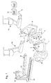
- the arrangement shown in FIG. 1 comprises a turntable 1.
- the turntable 1 there are several brackets 2 (e.g. four brackets 2) provided.
- the brackets 2 are for holding each a dome 4 determined.
- the domes 4 are for this purpose equipped with adapters 3, which are fixed to the brackets 2 can be.
- By turning the turntable 1 a dome 4 aligned with its adapter 3 so that the Dome 4 of a pivotally mounted in a bearing 9 Arm 8 captured and from the turntable 1, i.e. from the brackets 2 out of it, can be removed.
- the arm 8 that with Is pivotable with the help of an engine, on the one hand has one self-centering gripper 7, which is from the hollow (inner) Side of the calotte 4 forth on this in the area of the Dome 4 attached end of the adapter 3 attacks. Outdoors At the end of the arm 8, a clamp 6 is provided which adjusts in this way that it is attached to a free end of the adapter 3 provided rotary bearing 5 attacks.
- there sensors are provided, which the position of the calotte 4 and in particular the nest 4a into which a wafer 19 is inserted or from which a wafer 19 is to be removed.
- the loading spoon 15 serves individual Wafer 19 from a tray 16 and the transfer cylinder 10 to be positively controlled.
- an unloading spoon 12 is provided to the an unloading robot 13 is supported.
- the unloading spoon 12 takes over wafer 19 from the one raised upwards through the nest 4a Transfer cylinder 10 and moves the wafer 19 into one Quartz boat 18, being on the bracket for the quartz boat 18th Sensors 17 (preferably optical / laser sensors) are provided that identify the slot in the quartz boat 18 in the the wafer 19 from the unloading spoon 12 can be used.
- the Laser sensor 17 is along by a displacement device 20 of the quartz boat 18 slidable.
- the spoon 15 provided on the loading robot 14 removes one Wafer 19 from the tray 16 by gripping the back of the wafer.
- the wafer 19 is used by the Principle of holding with a gripper at the same time planarized.
- a station can be provided at which the Wafer flattened, centered and / or, in particular via barcode, be identified. This station can be between the Horde 16 and the loading robot 14 may be provided.
- the side of the wafer 19 to be processed must always be in the nest 4a to the inside of the calotte.
- the loading robot 14 becomes automatic so that the loading spoon 15 with the one to be processed Side of the wafer 19 to the nest 4a to be loaded is aligned. If the loading spoon 15 at the not too processing side of the wafer 19 engages - front side must be processed, it points downwards - the loading spoon lowers 15 and arranges the wafer 19 in the nest 4a of the calotte 4 on. Only then does the loading spoon 15 leave the wafer 19 going on when the one under the nest 4a of the calotte 4 Transfer cylinder 10 the wafer 19 by the Bernoulli principle planarized and stabilized.
- the loading spoon 15 aligned over the nest 4a to be loaded and grabs it on the side of the wafer to be processed 19 becomes the transfer cylinder 10 extended through the nest 4a in the calotte 4 and takes over the wafer 19 from the spoon 15 through the loading spoon 15 provided recesses.
- the loading spoon 15, which is now still between the wafer 19 and the upper end of the transfer cylinder 10 is now, by the loading robot 14th moved out to the side.
- the transfer cylinder 10 is then lowered so that the wafer 19 is arranged in the nest 4a of the calotte 4 becomes. Then the one assigned to the nest 4a Clamping device 100 closed and the wafer 19 in it Nest 4a of the calotte 4 fixed.
- the transfer cylinder 10 moves after the stop functions have been switched off down, and the dome 4 will close to the next one feeding nest 4a rotated. These steps will be continued until all nests of the calotte 4 are loaded with wafers 19 are. Then the dome 4 for further processing the wafer 19 held in it into a work station emotional. For this purpose, the calotte 4 can again be placed on the turntable 1 transferred and in a manner not shown to the processing station after removal from the turntable 1 are fed.
- the dome 4 is put back on the turntable 1, passed from the turntable 1 to the arm 8 and into the in Figure 1 moves, i.e. via their adapter 3 from the self-centering gripper 7 and the clamp 6 held and aligned so that the first nest 4a is facing for unloading the transfer cylinder 10 is arranged.
- the transfer cylinder 10 is with its front end to be removed Wafer 19 approximated, and the wafer 19 is - depending on Process - seized by the transfer cylinder 10 (back process) or planarized / stabilized (front process).
- the clamping device 100 is then opened.
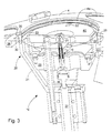
- the transfer cylinder 10, which of the calotte 4 or one Nest 4a thereof for inserting or removing wafers 19 is assigned to the nest 4a, is based on Fig. 3 described in more detail.
- the transfer cylinder 10 consists of an outer, cylindrical Part or cylindrical outer jacket 26, one with this movably connected head 25, which comes from an outer Part 31 and an inner part 28 there.
- guide rods 36 are attached, on which the inner part 28 of the head 25 is slidable and on carry a free device 40 for wafers 19 at their free ends.
- the guide rods 36 are hollow and guide Compressed air for the one located on the holding device 40 Bernoulli ring.
- the inner part 28 of the head 25 with its three reference stops 22 and the one attached in the middle Vacuum head 21 can extend over the nest 4a of the spherical cap 4 will take over a wafer 19 from the loading spoon 15 and drive back into the nest 4a.
- the reference stops 22 or the reference stops 22 themselves can be equipped with a vacuum function his.
- the head 25 of the transfer cylinder 10 is annular (Leaf) spring 30 can be pivoted elastically on the transfer cylinder 10 mounted.
- the transfer cylinder 10 is by moving its cylindrical outer jacket 26 adjustable up and down.
- the transfer cylinder 10 by moving the outer jacket 26 moved upwards via a servomotor 37 until the stops 35 (at least three) on the head 25 on the inside of the Dome 4 abut and thus the holding device 40 of the Head 25 is parallel to the nest 4a of the calotte 4.
- a wafer 19 on the holding device 40 of the transfer cylinder 10 can be planarized in the holding device 40 at least one, preferably annular, nozzle 27 or several nozzle bores aligned at an angle to the plane of the front end be provided, which is pressurized with compressed gas to a wafer 19 by the Bernoulli principle generated forces to the holding device 40 of the transfer cylinder 10 pull and planarize.
- the inner one Part 28 of the head 25 of the transfer cylinder 10 is on the Axes 36 also via an actuator 37, e.g. one Pressure motor or the like, movable up and down, so that the vacuum head 21 and the reference stops 22 through the nest 4a of the dome 4 can be moved around the wafer 19 to take over the corresponding process via the nest 4a or deliver.
- the transfer cylinder 10 is thus by axial adjustment its outer cylinder 26 from the inside against the edge of a Nest 4a moves until the pins 35 abut the edge of the nest 4a and at the same time align the head 25 parallel to the nest 4a.
- the holding device 40 in which the Bernoulli nozzle 27 and the vacuum head 21 is provided, since the latter moves to the Guide rods 36 is attached.
- each nest 4a is in the calottes 4 shows a device 100 for fixing a wafer 19 in the Assigned to nest 4a.
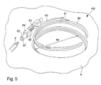
- These clamping devices 100 can, for example the embodiment shown in Figs. 4 and 5 have.
- Round disc 50 provided in all directions is tiltably supported on a swivel arm 51.
- a bolt 52 is attached to the disc 50, which is a double conical hole 53 in the free end of the pivot lever 51 interspersed.
- a spring 54 is provided which between the disc 50 and the free end of the swing arm 51st is arranged.
- the swivel arm 1 can be pivoted about a bearing 56, which is mounted next to the nest 4a on the calotte 4 is.
- drives described in more detail below can be used.
- a substantially round centering plate 57 for example provided such from thin elastic sheet metal, by the spring 54 against a projection 58 on the outside the disc 50 is pressed.
- the elastic centering plate 57 arrives first their downwardly angled edges 59 in contact with the Surrounding area of the nest 4a, so that the disc 50 is parallel is aligned to the nest 4a and thus when closing fully engages in nest level 4b of nest 4a.
- the Swing lever 51 is pivoted so far that spring 52 is slightly compressed so that the disc 50 is elastic against one lying on the edge on the step in the nest 55 Wafer 19 is pressed.
- a clamping ring 60 is provided which elastic connecting means, e.g. Leaf springs 61, at the ends an arc-shaped bracket 62 is attached.
- the Retaining bracket 62 in turn is via a pivot lever 63 and a shaft 65 carrying the pivot lever 63 in a pivot bearing 64 stored.
- a spring 66 is provided, which is biased so that it the clamping ring 60 in its active position, in which a wafer on the step is clamped lying on the edge of the nest 4a, loaded.
- the Clamping ring 60 is in its opposite bearing 64 Interrupted area to allow the movements of a spoon 14, 15 not disabled.
- any tool can be provided be that on the pivot lever 51 or the pivot bracket 61 supporting shaft 65 attacks.
- the Tool provided a polygon that fits into a corresponding Polygonal hole 67 engages in the shaft 65 to the clamping device 100 open.
- FIG. 6 One embodiment for a tool 110 for opening the Clamps 100 is shown in FIG. 6.
- This facility has a motor 70 which drives a polygon 71.
- the motor 70 is connected via two elastic connecting means, e.g. two leaf springs 72, connected to a carrier 73, which in turn over leaf springs 75 that become the first leaf springs 72 are aligned vertically, connected to a holding part 76 is.
- the holding part 76 is with an actuating robot (not shown) coupled.
Abstract
Description
Die Erfindung betrifft ein Verfahren zum Be- und Entladen von
Halbleiterwafern, insbesondere Dünnwafer oder dergleichen, in
bzw. aus Aufnahmeeinheiten gemäß dem Oberbegriff des Anspruchs
1 sowie eine Vorrichtung zum Be- und Entladen von
Halbleiterwafern in bzw. aus Aufnahmeeinheiten gemäß dem
Oberbegriff des Anspruchs 12, insbesondere zur Ausführung des
erfindungsgemäßen Verfahrens.The invention relates to a method for loading and unloading
Semiconductor wafers, in particular thin wafers or the like, in
or from recording units according to the preamble of the
Bei der Halbleiterherstellung sind für manche Verarbeitungsschritte oder Prozesse, z.B. der Metallisierung in Bedampfungsanlagen, besondere Aufnahmeeinheiten für Wafer, z.B. sogenannte Kalotten oder dergleichen, erforderlich. Zum Beladen dieser Kalotten müssen die Wafer z.B. aus sogenannten Horden entnommen und in Nester der Kalotte eingesetzt und eingeklemmt werden. Nach der Behandlung werden die Wafer aus den Nestern der Kalotte entnommen oder entladen und dann z.B. entweder in Quarzbooten oder wieder in Horden abgelegt. Für das Entnehmen von Wafern aus Horden und für das Einsetzen von Wafern in Quarzboote werden z.B. Greifer, sogenannte "Löffel" verwendet.In semiconductor manufacturing are for some processing steps or processes, e.g. metallization in vapor deposition systems, special receiving units for wafers, e.g. so-called Calottes or the like, required. For loading of these domes, the wafers e.g. from so-called hordes removed and inserted and clamped in nests of the calotte become. After the treatment, the wafers are removed from the Nests removed from the calotte or unloaded and then e.g. either placed in quartz boats or put back in hordes. For the removal of wafers from hordes and for the insertion of Wafers in quartz boats are e.g. Grippers, so-called "spoons" used.
Der Erfindung liegt die Aufgabe zugrunde, ein Verfahren und eine Vorrichtung der eingangs genannten Art anzugeben, mit welchen das Beladen von Aufnahmeeinheiten, insbesondere von Kalotten oder dergleichen, mit Wafern und das Entnehmen von Wafern aus Kalotten einfach und insbesondere durch das Prinzip der Zwangsübergabe möglich sind.The invention has for its object a method and to specify a device of the type mentioned, with which the loading of receiving units, especially of Dome or the like, with wafers and the removal of Wafers made from domes are simple and, in particular, by the principle handover is possible.
Die Aufgabe wird verfahrensmäßig durch ein gattungsgemäßes
Verfahren zum Be- und Entladen von Halbleiterwafern erfindungsgemäß
mit den kennzeichnenden Merkmalen des Anspruches 1
und vorrichtungsmäßig durch eine gattungsgemäße Vorrichtung
zum Be- und Entladen von Halbleiterwafern mit den kennzeichnenden
Merkmalen des Anspruchs 12 gelöst.The task is procedurally by a generic
Method for loading and unloading semiconductor wafers according to the invention
with the characterizing features of
Bevorzugte und vorteilhafte Ausgestaltungen des erfindungsgemäßen Verfahrens und der erfindungsgemäßen Vorrichtung sind jeweils Gegenstand der abhängigen Unteransprüche.Preferred and advantageous embodiments of the invention Method and the device according to the invention each subject of the dependent subclaims.
Beim gattungsgemäßen Verfahren zum Be- und Entladen von Halbleiterwafern, insbesondere Dünnwafern oder dergleichen, in bzw. aus Aufnahmeeinheiten werden Halbleiterwafer in oder aus Ausnehmungen einer Aufnahmeeinheit eingesetzt bzw., insbesondere nach einem Bearbeitungsschritt oder dergleichen, entnommen.In the generic method for loading and unloading semiconductor wafers, especially thin wafers or the like, in or from recording units become semiconductor wafers in or out Recesses of a receiving unit used or, in particular after a processing step or the like.
Das erfindungsgemäße Verfahren zum Be- und Entladen von Halbleiterwafern ist dadurch gekennzeichnet, dass der Halbleiterwafer beim Einsetzen und/oder beim Entnehmen in eine bzw. aus einer Ausnehmung gegenüber der Ausnehmung jeweils im wesentlichen zentriert angeordnet wird und dass der Halbleiterwafer während des Einsetzens und/oder Entnehmens in die bzw. aus der Ausnehmung jeweils in einer zur Ausnehmung im wesentlichen parallelen und/oder ebenen Ausrichtung gehalten wird. Dadurch wird erfindungsgemäß erreicht, dass das eigentliche Bewegen des jeweiligen Halbleiterwafers auf die Ausnehmung zu oder von ihr weg erfolgen kann, ohne dass nennenswerte Berührungen, insbesondere der Unterseite des jeweiligen Halbleiterwafers, und somit Beschädigungen der jeweiligen Oberfläche auftreten. Dies ermöglicht ein besonders einfaches und schnelles Beladen und Entladen der Wafer aus den Aufnahmeeinheiten.The inventive method for loading and unloading semiconductor wafers is characterized in that the semiconductor wafer when inserting and / or removing in or out a recess relative to the recess in each case essentially is centered and that the semiconductor wafer during insertion and / or removal in or out of the recess in each case essentially to the recess parallel and / or planar alignment is maintained. It is thereby achieved according to the invention that the actual Moving the respective semiconductor wafer towards the recess or can take place away from it without noticeable touching, in particular the underside of the respective semiconductor wafer, and thus damage to the respective surface occur. This enables a particularly simple and rapid loading and unloading of the wafers from the holding units.
Dabei ist es insbesondere bevorzugt, dass das Verfahren zum
Be- und/oder Entladen von als Kalotten ausgebildeten Aufnahmeeinheiten
mit einer Mehrzahl von als Nester ausgebildete
Ausnehmungen vorgesehen und geeignet ist. Dies ist deshalb
vorteilhaft, weil sich gerade Kalotten mit Nestern als Ausnehmungen
als Aufnahmeeinheiten bei der Massenproduktion von
Halbleiterwafern anbieten und durchgesetzt haben.
Es ist weiter von Vorteil, dass gemäß einer weiteren Ausführungsform
dieses erfindungsgemäßen Verfahrens der Halbleiterwafer
bei einer Bewegung von und/oder zur Ausnehmung auf einer
Seite gehalten wird, die nicht zu behandeln ist bzw.
nicht behandelt wurde. Dadurch wird ebenfalls ein Beschädigen
oder Verunreinigen der zu behandelnden oder der behandelten
Oberfläche weitestgehend vermieden, und die Bewegung selbst
und somit das Be- und/oder Entladen kann zügig erfolgen.It is particularly preferred that the method is provided and suitable for loading and / or unloading receiving units designed as spherical caps with a plurality of recesses designed as nests. This is advantageous because, in particular, domes with nests as recesses offer themselves as receiving units in the mass production of semiconductor wafers and have prevailed.
It is furthermore advantageous that, according to a further embodiment of this method according to the invention, the semiconductor wafer is held on a side during a movement from and / or to the recess, which side cannot be treated or has not been treated. This also largely prevents damage or contamination of the surface to be treated or the treated surface, and the movement itself and thus the loading and / or unloading can take place rapidly.
Ein besonders sicheres Handhaben ohne nennenswerte mechanische Insulzien auf die jeweiligen Oberflächen ergibt sich, wenn gemäß einer weiteren Ausführungsform des erfindungsgemäßen Verfahrens der Halbleiterwafer jeweils durch Einwirken von Unterdruck und/oder durch Einwirken von durchströmendes Gas, insbesondere nach dem Benoulli-Prinzip entstehende Kräfte ausgerichtet und insbesondere eben gehalten oder planarisiert wird, insbesondere während er bewegt wird.A particularly safe handling without significant mechanical Insulants on the respective surfaces result if according to a further embodiment of the invention Process of the semiconductor wafer each by exposure of negative pressure and / or by the action of flowing through Gas, especially the forces generated by the Benoulli principle aligned and in particular kept level or planarized especially when it is being moved.
Für eine gute Anpassung und ein gutes Einsetzen bzw. Entnehmen eines Halbleiterwafers wird es bevorzugt, dass der Halbleiterwafer auf einer der Ausnehmung, in welche oder von welcher er einzusetzen bzw. zu entnehmen ist, zugekehrten Seite gehalten wird. Dies sichert ein Abstützen beim zu Bewegen auf die Ausnehmung bzw. beim Fortbewegen von der Ausnehmung.For a good adjustment and a good insertion or removal of a semiconductor wafer, it is preferred that the semiconductor wafer on one of the recesses, into or from which it is to be used or removed, facing side is held. This ensures a support when moving the recess or when moving away from the recess.
Gemäß einer weiteren Ausführungsform ist es vorgesehen, dass der Halbleiterwafer durch Halten an dieser Unterseite in bezug auf die Ausnehmung bewegt und/oder zentriert wird.According to a further embodiment, it is provided that the semiconductor wafer by holding against this bottom is moved and / or centered on the recess.
Ein besonders schonendes Einsetzen bzw. Entnehmen eines Halbleiterwafers ergibt sich, wenn gemäß einer anderen Ausführungsform des erfindungsgemäßen Verfahrens die auf den Halbleiterwafer einwirkenden Kräfte während des Ausrichtens gegenüber der Ausnehmung im wesentlichen aufgehoben werden, insbesondere bevor der Halbleiterwafer jeweils endgültig in der Ausnehmung angeordnet wird oder ist.A particularly gentle insertion or removal of a semiconductor wafer arises if according to another embodiment of the method according to the invention on the semiconductor wafer acting forces during alignment the recess are essentially removed, especially before the semiconductor wafer is finally in the recess is or is arranged.
Entsprechend werden beim Entladen von Halbleiterwafern aus Ausnehmungen einer Aufnahmeeinheit die Verfahrensschritte im Wesentlichen in sinngemäß umgekehrter Vorgehensweise oder Verfahrensweise ausgeführt wie beim Beladen der Aufnahmeeinheit.Accordingly, when unloading semiconductor wafers Recesses of a receiving unit, the process steps in Essentially in the reverse procedure or Procedure carried out as when loading the receiving unit.
Eine für weitere Verarbeitungsschritte sowie für das Einsetzen und Entnehmen besonders günstige Vorgehensweise ergibt sich, wenn der Halbleiterwafer nach dem Beladen in der Ausnehmung durch wenigstens in seinem Randbereich auf ihn wirkende und/oder zur Ausnehmung im wesentlichen senkrecht ausgerichtete Kräfte gehaltert, insbesondere geklemmt wird. Dadurch wird zum Beispiel auch erreicht, dass ausschließlich in diesen Randbereichen, welche gegebenenfalls relativ schmal und in ihrem Flächenanteil gering ausgelegt werden können, mechanische Belastungen oder Insulzien auftreten.One for further processing steps and for insertion and removal results in a particularly favorable procedure itself when the semiconductor wafer is loaded into the recess by acting on it at least in its edge area and / or substantially perpendicular to the recess Forces are held, in particular clamped. Thereby is also achieved, for example, that only in these edge areas, which may be relatively narrow and can be designed to be small in terms of their surface area, mechanical loads or insulants occur.
Gemäß einer weiteren Ausführungsform des erfindungsgemäßen Verfahrens wird die Aufnahmeeinheit in eine Be- bzw. Entladeposition oder -stellung bewegt. Ferner wird die jeweils zu be- und/oder entladende Ausnehmung der Aufnahmeeinheit durch Verdrehen der Aufnahmeeinheit um eine Achse in die Be- oder Entladeposition bewegt.According to a further embodiment of the invention The receiving unit is moved into a loading or unloading position or position moved. Furthermore, each becomes loading and / or unloading recess of the receiving unit Rotating the receiving unit about an axis in the loading or Unloading position moved.
Bei der erfindungsgemäßen Vorgehensweise wird bevorzugt, dass beim Entladen eines Halbleiterwafers aus einer Ausnehmung der Ausnahmeeinheit der Halbleiterwafer jeweils in einer im wesentlichen parallelen und/oder ebenen Lage zur Ausnehmung gehalten wird, vorzugsweise durch strömendes Gas und/oder durch nach dem Benoulli-Prinzip entstehende Kräfte, bevor den Halbleiterwafer jeweils in der Ausnehmung halternde und/oder klemmende Kräfte aufgehoben werden. In the procedure according to the invention, it is preferred that when unloading a semiconductor wafer from a recess of the Exceptional unit of the semiconductor wafers each in one essentially kept parallel and / or flat position to the recess is, preferably by flowing gas and / or by Forces created according to the Benoulli principle before the semiconductor wafer each holding in the recess and / or clamping forces are released.
Die erfindungsgemäße Vorrichtung zum Be- und/oder Entladen von Halbleiterwafern, insbesondere Dünnwafern oder dergleichen, in bzw. aus Aufnahmeeinheiten ist insbesondere zur Ausführung des erfindungsgemäßen Verfahrens geeignet und dadurch gekennzeichnet, dass eine Halteeinrichtung für mindestens eine Aufnahmeeinheit vorgesehen ist, mit welcher die Aufnahmeeinheit in eine Be- und/oder eine Entladeposition bewegbar ist. Es ist ferner vorgesehen, dass im Bereich der Be- und/oder Entladeposition mindestens eine Übergabeeinrichtung vorgesehen ist, welche in Richtung einer Achse einer Ausnehmung in der Aufnahmeeinheit gegenüber der Ausnehmung verstellbar ist. Des Weiteren ist es vorgesehen, dass wenigstens eine Beladeeinrichtung und/oder wenigstens eine Entladeeinrichtung zum Bewegen von Halbleiterwafern zu bzw. von einer in der Be- bzw. Entladeposition befindlichen Aufnahmeeinheit vorgesehen sind. Durch das Kooperieren der Halteeinrichtung der Übergabeeinrichtung sowie der Be- und Entladeeinrichtung wird erreicht, dass eine gegebene Aufnahmeeinheit besonders rasch und auf einfache Art und Weise unter weitestgehender Vermeidung mechanischer Einflüsse auf die Halbleiterwafer mit Halbleiterwafern beladen oder von diesen entladen werden kann.The device according to the invention for loading and / or unloading of semiconductor wafers, in particular thin wafers or the like, in or out of receiving units is especially for execution suitable of the method according to the invention and thereby characterized in that a holding device for at least one Recording unit is provided with which the recording unit movable into a loading and / or unloading position is. It is also envisaged that in the area of and / or unloading position at least one transfer device is provided, which is in the direction of an axis of a recess adjustable in the receiving unit in relation to the recess is. Furthermore, it is provided that at least a loading device and / or at least one unloading device for moving semiconductor wafers to or from a receiving unit in the loading or unloading position are provided. By cooperating with the holding device the transfer device and the loading and unloading device is achieved that a given recording unit special quickly and easily, as far as possible Avoidance of mechanical influences on the semiconductor wafers Semiconductor wafers are loaded or unloaded by them can.
Die erfindungsgemäße Vorrichtung ist vorzugsweise zum Be- und/oder Entladen von als Kalotten oder dergleichen ausgebildete Aufnahmeeinheiten mit einer Mehrzahl fester oder dergleichen ausgebildeter Ausnehmungen vorgesehen und geeignet.The device according to the invention is preferably for loading and / or unloading of calottes or the like Recording units with a plurality of fixed or the like trained recesses provided and suitable.
Als Übergabeeinrichtung ist insbesondere eine solche vorgesehen, die im wesentlichen als Übergabezylinder oder dergleichen ausgebildet ist oder mindestens einen solchen aufweist.Such a transfer device is provided in particular, which essentially as a transfer cylinder or the like is formed or has at least one.
Es ist des Weiteren vorgesehen, dass die mindestens eine Beladeeinrichtung und/oder die mindestens eine Entladeeinrichtung jeweils im wesentlichen als Be- bzw. als Entladelöffel oder dergleichen ausgebildet sind oder jeweils einen solchen aufweisen. It is further provided that the at least one loading device and / or the at least one unloading device each essentially as a loading or unloading spoon or the like are formed or each such exhibit.
Gemäß einer weiteren Ausführungsform der erfindungsgemäßen Vorrichtung ist es vorgesehen, dass die Beladeeinrichtung aus einer einem ersten Halbleiterreservoir, insbesondere einer Horde oder dergleichen, zugeordneten Stellung in die der Be- und/oder Entladeposition der Aufladeeinheit zugeordneten Stellung und von dort zurückbewegbar ausgebildet ist.According to a further embodiment of the invention The device provides that the loading device is made of a first semiconductor reservoir, in particular one Horde or the like, assigned position in the and / or unloading position assigned to the charging unit Position and can be moved back from there.
Entsprechend ist es vorgesehen, dass die Entladeeinrichtung aus einer der Be- bzw. Entladeposition der Aufnahmeeinheit zugeordneten Stellung in eine einem zweiten Halbleiterwaferreservoir, insbesondere einem Quarzboot oder dergleichen, und/oder einer Horde oder dergleichen zugeordneten Stellung und von dort zurückbewegbar ausgebildet ist.Accordingly, it is provided that the unloading device from one of the loading and unloading positions of the receiving unit assigned position in a second semiconductor wafer reservoir, especially a quartz boat or the like, and / or a position assigned to a horde or the like and can be moved back from there.
Die beiden zuletzt genannten Maßnahmen schaffen eine hohe Flexibilität und Beweglichkeit der jeweiligen Be- und/oder Entladeeinrichtungen und ermöglichen somit eine hohe Verarbeitungsrate.The latter two measures create a high level Flexibility and mobility of the respective loading and / or Unloading devices and thus enable a high processing rate.
Um die jeweiligen Bewegungen der Be- und/oder Entladeeinrichtungen zu gewährleisten, ist es gemäß einer weiteren Ausführungsform der erfindungsgemäßen Vorrichtung vorgesehen, jeweils mindestens eine Bewegungseinrichtung auszubilden. Diese kann vorteilhafterweise als Bewegungsroboter oder dergleichen vorgesehen sein.To the respective movements of the loading and / or unloading devices to ensure it is according to a further embodiment provided the device according to the invention, each train at least one movement device. This can advantageously be used as a motion robot or the like be provided.
Zur Gewährleistung einer sicheren Weiterverarbeitung und eines sicheren Transportes ist es gemäß einer weiteren Ausführungsform der erfindungsgemäßen Vorrichtung vorgesehen, dass mindestens eine Haltevorrichtung zum Halten mindestens einer Aufnahmeeinheit in der Be- und/oder Entladeposition ausgebildet ist.To ensure safe further processing and one it is safe transport according to a further embodiment the device according to the invention provided that at least one holding device for holding at least one Recording unit formed in the loading and / or unloading position is.
Vorteilhafterweise weist die eine Haltevorrichtung mindestens einen verschwenkbaren Arm auf oder ist als solcher ausgebildet. Ferner ist es vorgesehen, dass an dem Arm ein von innen her an der Aufnahmeeinheit anlegbarer Greifer oder dergleichen und/oder eine an der Aufnahmeeinheit außen an einem vorgesehenen Adapter oder dergleichen angreifende Klemme oder dergleichen ausgebildet sind.The holding device advantageously has at least one a pivotable arm or is designed as such. It is also provided that an inside of the arm forth on the receiving unit gripper or the like and / or one provided on the outside of the receiving unit Adapter or the like attacking clamp or the like are formed.
Es ist ferner von Vorteil, dass durch den Arm die Aufnahmeeinheit um ihre Achse verdrehbar halterbar ist. Ferner ist es vorgesehen, dass der Arm in einem Lager um eine Achse, gegebenenfalls durch motorischen Antrieb oder dergleichen, verschwenkbar ausgebildet ist.It is also advantageous that the receiving unit by the arm can be held rotatably about its axis. Furthermore, it is provided that the arm in a bearing about an axis, if necessary by motor drive or the like, pivotable is trained.
Dabei wird bevorzugt, dass der Haltevorrichtung zum Haltern von Aufnahmeeinheiten, insbesondere bestehend aus dem Arm, dem vorzugsweise selbstzentrierenden Greifer und der Klemme, ein Drehtisch mit mehreren Halterungen für Adapter einer Mehrzahl von Aufnahmeeinheiten zugeordnet vorgesehen ist.It is preferred that the holding device for holding of recording units, in particular consisting of the arm, the preferably self-centering gripper and the clamp, a turntable with multiple brackets for one adapter A plurality of receiving units is provided.
Es ist ferner von Vorteil, dass der sich in der Be- bzw. Entladestellung befindlichen Ausnehmung der Aufnahmeeinheit eine Übergabeeinrichtung, insbesondere ein Übergabezylinder oder dergleichen, zugeordnet vorgesehen ist.It is also advantageous that the is in the loading or unloading position located recess of the receiving unit Transfer device, in particular a transfer cylinder or the like, is provided assigned.
Dabei wird bevorzugt, dass die Übergabeeinrichtung, insbesondere der Übergabezylinder einen Kopf aufweist, der in eine zur Ebene der Ausnehmung parallele Lage oder Anordnung verstellbar ausgebildet ist. Dies ermöglicht ein entsprechendes Vor- und Zurückbewegen um einen zu positionierenden Halbleiterwafer entsprechend sanft abzustützen und in der Ausnehmung der Aufnahmeeinheit zu positionieren oder ihn aus dieser herauszuheben.It is preferred that the transfer device, in particular the transfer cylinder has a head that fits into a parallel position or arrangement adjustable to the level of the recess is trained. This enables a corresponding one Moving back and forth around a semiconductor wafer to be positioned accordingly gently support and in the recess position the pickup unit or lift it out of it.
Es ist ferner vorteilhaft, dass an dem der Ausnehmung zugekehrten Ende der Übergabeeinrichtung wenigstens ein Vakuumkopf und/oder wenigstens eine Düse für den Austritt von Druckgas vorgesehen ist. It is also advantageous that on the facing the recess At least one vacuum head at the end of the transfer device and / or at least one nozzle for the discharge of Compressed gas is provided.
Dieser Vakuumkopf und/oder die Düse sind zum Erzeugen von Kräften nach dem Benoulli-Prinzip ausgebildet und somit geeignet, ein möglichst sanftes Haltern und Lagern eines zu positionierenden Halbleiterwafers zu gewährleisten.This vacuum head and / or the nozzle are for generating Forces trained according to the Benoulli principle and therefore suitable as gently as possible holding and storing one to be positioned Ensure semiconductor wafers.
Ebenfalls zu einer besonders günstigen Positionierbarkeit ist es vorgesehen, dass an dem der Ausnehmung jeweils zugekehrten Ende der Übergabeeinrichtung Referenzanschläge vorgesehen sind, welche gegenüber der Ausnehmung verschiebbar ausgebildet sind.Is also a particularly favorable positionability it is provided that on the one facing the recess Reference stops provided at the end of the transfer device are, which are designed to be displaceable relative to the recess are.
Des Weiteren ist vorgesehen, dass der Kopf der Übergabeeinrichtung an einem äußeren, in etwa zylindrischen Teil der Übergabeeinrichtung im wesentlichen elastisch verschwenkbar gehaltert ist.Furthermore, it is provided that the head of the transfer device on an outer, approximately cylindrical part of the Transfer device can be pivoted essentially elastically is supported.
Dabei ist es ferner von Vorteil, dass an dem Kopf mehrere Anschlagstifte vorgesehen sind, welche zum Zentrieren des Kopfes der Übergabeeinrichtung, insbesondere im Umfangsbereich einer Ausnehmung, an der Aufnahmeeinheit anlegbar vorgesehen sind.It is also advantageous that several stop pins on the head are provided, which for centering the head the transfer device, especially in the peripheral area a recess provided on the receiving unit are.
Es ist gegebenenfalls jeder Ausnehmung der Aufnahmeeinheit eine einen Halbleiterwafer in der Ausnehmung fixierende Fixiereinrichtung, insbesondere als eine in das Nest klemmende Vorrichtung, zugeordnet vorgesehen. Dadurch wird ein Haltern und Fixieren des jeweiligen Halbleiterwafers, insbesondere während eines weiterverarbeitenden Prozessschrittes gewährleistet.It may be any recess in the receiving unit a fixing device fixing a semiconductor wafer in the recess, especially as a jam in the nest Device, assigned provided. This becomes a keeper and fixing the respective semiconductor wafer, in particular guaranteed during a further processing step.
Es ist bevorzugt, dass die Fixiervorrichtung, insbesondere zum Klemmen eines Halbleiterwafers in einem Nest, eine an einem Schwenkhebel gegenüber diesem kippbar gelagerte Scheibe aufweist. Weiterhin vorteilhaft ist, dass mit Abstand von der Scheibe unterhalb des Schwenkhebels eine Zentrierscheibe mit nach unten abgewinkeltem Rand vorgesehen ist, um die Scheibe gegenüber dem Halbleiterwafer parallel zu stellen, bevor die Scheibe im Halbleiterwafer anliegt.It is preferred that the fixing device, in particular for clamping a semiconductor wafer in a nest, one on one Swivel lever opposite this tilting disc having. It is also advantageous that at a distance from the Disc under the swivel lever with a centering disc angled edge is provided around the disc compared to the semiconductor wafer before the Disc rests in the semiconductor wafer.
Alternativ und/oder zusätzlich ist es vorgesehen, dass die Fixiervorrichtung jeweils einen, insbesondere wenigstens einmal unterbrochenen, Klemmring aufweist. Dabei ist vorteilhaft, dass der Klemmring über einen Haltebügel und einen Schwenkhebel an der Aufnahmeeinheit, insbesondere Kalotte oder dergleichen, verschwenkbar gelagert ist.Alternatively and / or additionally, it is provided that the Fixing device one, in particular at least once interrupted, clamping ring. It is advantageous that the clamping ring has a bracket and a Swivel lever on the mounting unit, especially the calotte or the like, is pivotally mounted.
Ferner ist es dabei von Vorteil, dass der Klemmring mit dem Haltebügel durch elastische Mittel, insbesondere durch Blattfedern oder dergleichen, verbunden ist.It is also advantageous that the clamping ring with the Retaining bracket by elastic means, in particular by leaf springs or the like.
Mit dem erfindungsgemäßen Verfahren wird durch die sinnvolle Abstimmung der einzelnen Stufen des Verfahrens ein schonendes Handhaben auch dünner und/oder großer Wafer gewährleistet, wobei auch sichergestellt ist, dass das Beladen und das Entladen der Kalotten durch Einsetzen von Wafern in die Nester bzw. das Entnehmen von Wafern aus den Nestern in kurzer Zeit möglich ist.With the method according to the invention is the sensible Coordination of the individual stages of the process is gentle Handling even thin and / or large wafers guaranteed also ensuring that loading and unloading the domes by inserting wafers into the nests or the removal of wafers from the nests in a short time is possible.
Die bei dem Verfahren und mit der Vorrichtung gemäß der Erfindung verwirklichte Zwangsübergabe von Wafern erlaubt es, dass bei der Übergabe von Wafern vom Greifer zu einer Einrichtung, die beispielsweise ein Übergabezylinder ist und die den Wafer jeweils übernimmt und in ein Nest der Kalotte bewegt und umgekehrt, zum Zeitpunkt der Übergabe beide Systeme aktiv sind. Dabei wird der Wafer jeweils hauptsächlich nur an einer Seite, vorzugsweise der Rückseite, berührt. Weiterhin ist durch die verwendete Vorgehensweise eine relativ kurze Taktzeit möglich.The in the method and with the device according to the invention realized handover of wafers allows that when wafers are transferred from the gripper to a facility, which is for example a transfer cylinder and which takes over the wafer and moves it into a nest of the spherical cap and vice versa, at the time of delivery both systems are active. The wafer is mainly only on one side, preferably the back. Farther is a relatively short one due to the procedure used Cycle time possible.
Weitere Einzelheiten und Merkmale des erfindungsgemäßen Verfahrens und der Vorrichtung ergeben sich aus der nachstehenden Beschreibung von in den Zeichnungen gezeigten Ausführungsbeispielen.
- Fig. 1
- ist eine schematische und perspektivische Gesamtansicht einer Anordnung gemäß der Erfindung, auf der insbesondere das Verfahren ausgeführt werden kann.
- Fig. 2
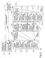
- zeigt ein Flussdiagramm einer Ausführungsform des erfindungsgemäßen Verfahrens.
- Fig. 3
- zeigt in einer perspektivischen und teilweise geschnittenen Seitenansicht eine Vorrichtung (Übergabezylinder) zum Einsetzen/Entnehmen von Wafern in das/aus einem Nest.
- Fig. 4
- zeigt eine Ausführungsform einer Einrichtung zum Halten eines Wafers in einem Nest einer Kalotte.
- Fig. 5
- zeigt eine weitere Ausführungsform einer Einrichtung zum Halten eines Wafers in einem Nest einer Kalotte.
- Fig. 6
- zeigt eine selbstzentrierende Vorrichtung zum Betätigen
der Einrichtungen gemäß Fig. 4
oder 5.
- Fig. 1
- is a schematic and perspective overall view of an arrangement according to the invention, on which in particular the method can be carried out.
- Fig. 2
- shows a flow diagram of an embodiment of the method according to the invention.
- Fig. 3
- shows a perspective and partially sectioned side view of a device (transfer cylinder) for inserting / removing wafers in / from a nest.
- Fig. 4
- shows an embodiment of a device for holding a wafer in a nest of a spherical cap.
- Fig. 5
- shows a further embodiment of a device for holding a wafer in a nest of a spherical cap.
- Fig. 6
- shows a self-centering device for operating the devices according to FIG. 4 or 5.
Die in Fig. 1 gezeigte Anordnung umfasst einen Drehtisch 1.
An dem Drehtisch 1 sind mehrere Halterungen 2 (z.B. vier Halterungen
2) vorgesehen. Die Halterungen 2 sind zum Halten jeweils
einer Kalotte 4 bestimmt. Hierzu sind die Kalotten 4
mit Adaptern 3 ausgestattet, die an den Halterungen 2 festgelegt
werden können. Durch Verdrehen des Drehtisches 1 wird
eine Kalotte 4 mit ihrem Adapter 3 so ausgerichtet, dass die
Kalotte 4 von einem in einem Lager 9 verschwenkbar gelagerten
Arm 8 erfasst und vom Drehtisch 1, d.h. aus den Halterungen 2
desselben heraus, abgenommen werden kann. Der Arm 8, der mit
Hilfe eines Motors verschwenkbar ist, besitzt einerseits einen
selbstzentrierenden Greifer 7, der von der hohlen (inneren)
Seite der Kalotte 4 her an dieser im Bereich des an der
Kalotte 4 befestigten Endes des Adapters 3 angreift. Am freien
Ende des Armes 8 ist eine Klemme 6 vorgesehen, die so verstellt
wird, dass sie an einem am freien Ende des Adapters 3
vorgesehenen Drehlager 5 angreift.The arrangement shown in FIG. 1 comprises a
Der selbstzentrierende Greifer 7 und das Lager 5, das in der
Klemme 6 am Arm 8 aufgenommen ist, erlauben, dass die Kalotte
4 um ihre Achse drehbar ist, um eines ihrer Nester 4a in die
Position auszurichten, in der ein Wafer 19 in das Nest 4a
eingesetzt bzw. aus dem Nest 4a entnommen werden kann. Dabei
sind Sensoren vorgesehen, welche die Lage der Kalotte 4 und
insbesondere des Nestes 4a, in das ein Wafer 19 eingesetzt
oder aus dem ein Wafer 19 entnommen werden soll, feststellen.The self-centering gripper 7 and the
Dem Arm 8, der eine Kalotte 4 in der Lade- bzw. Entladeposition
hält, ist ein Übergabezylinder 10 zugeordnet, der in
mehr Einzelheiten später an Hand der Fig. 3 beschrieben werden
wird und mit dem ein Wafer 19 von einem Beladelöffel 15,
der an einem Beladeroboter 14 montiert ist, übernommen und
durch Absenken des Übergabezylinders 10 in das Nest 4a eingesetzt
werden kann. Der Beladelöffel 15 dient dazu, einzelne
Wafer 19 aus einer Horde 16 zu entnehmen und dem Übergabezylinder
10 zwangsgesteuert zu übergeben.The
In der Anordnung ist ein Entladelöffel 12 vorgesehen, der an
einem Entladeroboter 13 gehaltert ist. Der Entladelöffel 12
übernimmt Wafer 19 von dem nach oben durch das Nest 4a hochgefahrenen
Übergabezylinder 10 und bewegt den Wafer 19 in ein
Quarzboot 18, wobei an der Halterung für das Quarzboot 18
Sensoren 17 (vorzugsweise optische-/Lasersensoren) vorgesehen
sind, die den Schlitz im Quarzboot 18 identifizieren, in den
der Wafer 19 vom Entladelöffel 12 eingesetzt werden kann. Der
Lasersensor 17 ist durch eine Verschiebevorrichtung 20 entlang
des Quarzbootes 18 verschiebbar. In the arrangement, an unloading
Mit der beschriebenen und in Fig. 1 gezeigten Anordnung kann so gearbeitet werden, wie dies nachstehend an Hand von Fig. 2 erläutert wird.With the arrangement described and shown in Fig. 1 can can be worked as follows with reference to FIG. 2 is explained.
Der am Laderoboter 14 vorgesehene Löffel 15 entnimmt einen
Wafer 19 aus der Horde 16, und zwar durch Greifen an der Waferrückseite.
Der Wafer 19 wird dabei durch das verwendete
Prinzip des Haltens mit einem Greifer gleichzeitig planarisiert.The
Zusätzlich kann eine Station vorgesehen sein, bei welcher die
Wafer geflattet, zentriert und/oder, insbesondere über Barcode,
identifiziert werden. Diese Station kann zwischen der
Horde 16 und dem Beladeroboter 14 vorgesehen sein.In addition, a station can be provided at which the
Wafer flattened, centered and / or, in particular via barcode,
be identified. This station can be between the
Die zu bearbeitende Seite des Wafers 19 muss im Nest 4a immer
zum Kalotteninneren zeigen. Dazu wird der Laderoboter 14 automatisch
so bewegt, dass der Beladelöffel 15 mit der zu bearbeitenden
Seite des Wafers 19 zum zu beladenden Nest 4a hin
ausgerichtet ist. Wenn der Beladelöffel 15 an der nicht zu
bearbeitenden Seite des Wafers 19 greift - Vorderseite muss
prozessiert werden, sie zeigt nach unten - senkt sich der Beladelöffel
15 und ordnet den Wafer 19 in das Nest 4a der Kalotte
4 an. Der Beladelöffel 15 lässt den Wafer 19 erst dann
los, wenn der sich unter dem Nest 4a der Kalotte 4 befindliche
Übergabezylinder 10 den Wafer 19 durch das Bernoulli-Prinzip
planarisiert und stabilisiert. Nach dem Zurückfahren
des Beladelöffels 15 aus dem Nest 4a der Kalotte 4 wird eine
dem Nest 4a zugeordnete Klemmvorrichtung 100, die beispielsweise
die nachstehend an Hand der Fig. 4 oder 5 beschriebene
Ausführungsform haben kann, geschlossen und die Kalotte 4 so
gedreht, dass das nächste Nest mit einem Wafer beschickt werden
kann.The side of the wafer 19 to be processed must always be in the
Ist der Beladelöffel 15 über dem zu beladenden Nest 4a ausgerichtet
und greift er an der zu bearbeitenden Seite des Wafers
19 (Rückseite des Wafers) an, wird der Übergabezylinder
10 durch das Nest 4a in der Kalotte 4 ausgefahren und übernimmt
den Wafer 19 vom Löffel 15 durch am Beladelöffel 15
vorgesehene Aussparungen. Der Beladelöffel 15, der sich jetzt
noch zwischen den Wafer 19 und dem oberen Ende des Übergabezylinders
10 befindet, wird nun durch den Laderoboter 14
seitlich herausgefahren. Der Übergabezylinder 10 wird danach
abgesenkt, damit der Wafer 19 im Nest 4a der Kalotte 4 angeordnet
wird. Anschließend wird die dem Nest 4a zugeordnete
Klemmvorrichtung 100 geschlossen und der Wafer 19 damit im
Nest 4a der Kalotte 4 fixiert.Is the
Der Übergabezylinder 10 fährt nach Abschalten der Haltefunktionen
nach unten, und die Kalotte 4 wird bis zum nächsten zu
beschickenden Nest 4a gedreht. Diese Arbeitsschritte werden
fortgesetzt, bis alle Nester der Kalotte 4 mit Wafern 19 beschickt
sind. Dann wird die Kalotte 4 zur weiteren Bearbeitung
der in ihr gehalterten Wafer 19 in eine Arbeitsstation
bewegt. Hierzu kann die Kalotte 4 wieder auf den Drehtisch 1
übergeben und auf nicht näher gezeigte Weise der Bearbeitungsstation
nach Abnahme vom Drehtisch 1 zugeführt werden.The
Sobald die Bearbeitung/Behandlung (das "Bearbeiten") der Wafer
19 auf der Kalotte 4 in der Bearbeitungsstation beendet
ist, wird die Kalotte 4 wieder an den Drehtisch 1 angesetzt,
von dem Drehtisch 1 auf den Arm 8 übergeben und in die in
Fig. 1 gezeigte Lage bewegt, d.h. über ihren Adapter 3 von
dem selbstzentrierenden Greifer 7 und der Klemme 6 gehalten
und so ausgerichtet, dass das erste Nest 4a zum Entladen gegenüber
dem Übergabezylinder 10 angeordnet ist. Der Übergabezylinder
10 wird mit seinem vorderen Ende dem zu entnehmenden
Wafer 19 angenähert, und der Wafer 19 wird - abhängig vom
Prozess - durch den Übergabezylinder 10 ergriffen (Rückseitenprozess)
oder planarisiert/stabilisiert (Vorderseitenprozess).
Darauf wird die Klemmvorrichtung 100 geöffnet. Hat der
Übergabezylinder 10 den Wafer 19 ergriffen, fährt dieser
durch das Nest 4a nach oben und übergibt den Wafer 19 an den
Entladelöffel 12 durch rückwärtige Schrittabfolge des oben
beschriebenen Beladeprozesses. Wurde der Wafer 19 durch den
Übergabezylinder 10 nur planarisiert/stabilisiert, senkt sich
der Entladelöffel 12 und übernimmt den Wafer 19 aus dem Nest
4a. Der Entladeroboter 13 setzt nun den Wafer 19 automatisch
in das Quarzboot 18, wobei der Schlitz in dem Quarzboot 18,
in das der Wafer 19 einzusetzen ist, durch geeignete Sensorik
17 - vorzugsweise optisch mittels Laser - lokalisiert wird.Once the processing / treatment (the "processing") of the wafer
19 ended on the
Der Übergabezylinder 10, welcher der Kalotte 4 bzw. einem
Nest 4a derselben zum Einsetzen bzw. Entnehmen von Wafern 19
in das Nest 4a zugeordnet ist, wird nachstehend an Hand von
Fig. 3 näher beschrieben.The
Der Übergabezylinder 10 besteht aus einem äußeren, zylinderförmigen
Teil oder zylindrischem Außenmantel 26, einem mit
diesem beweglich verbundenen Kopf 25, der aus einem äusseren
Teil 31 und einem inneren Teil 28 besteht. Im äusseren Teil
31 des Kopfes 25 sind Führungsstangen 36 befestigt, auf denen
der innere Teil 28 des Kopfes 25 verschiebbar ist und die an
ihren freien Enden eine Halteeinrichtung 40 für Wafer 19 tragen.
Weiterhin sind die Führungsstangen 36 hohl und führen
Druckluft für den an der Halteeinrichtung 40 befindlichen
Bernoulli-Ring. Der innere Teil 28 des Kopfes 25 mit seinen
drei Referenzanschlägen 22 und dem in der Mitte befestigten
Vakuumkopf 21 kann über das Nest 4a der Kalotte 4 ausgefahren
werden, einen Wafer 19 vom Beladelöffel 15 übernehmen und
wieder in das Nest 4a einfahren. Beim Entladen gibt der innere
Teil 28 des Kopfes 25 einen Wafer 19 an den Entladelöffel
12 ab. Im Bereich der Referenzanschläge 22 oder die Referenzanschäge
22 selbst können mit einer Vakuumfunktion versehen
sein.The
Der Kopf 25 des Übergabezylinders 10 ist über eine ringförmige
(Blatt-)Feder 30 elastisch verschwenkbar am Übergabezylinder
10 montiert. Der Übergabezylinder 10 ist durch Verschieben
seines zylindrischen Außenmantels 26 auf und ab verstellbar.
Beim Be- und Entladen eines Wafers 19 aus dem Nest 4a
wird unabhängig von der zu bearbeitenden Seite des Wafers 19
der Übergabezylinder 10 über das Verschieben des Außenmantels
26 über einen Stellmotor 37 nach oben gefahren, bis die Anschläge
35 (wenigstens drei) am Kopf 25 an der Innenseite der
Kalotte 4 anliegen und sich somit die Halteeinrichtung 40 des
Kopfes 25 parallel zum Nest 4a der Kalotte 4 befindet.The
Um einen Wafer 19 auf der Halteeinrichtung 40 des Übergabezylinders
10 zu planarisieren, können in der Halteeinrichtung
40 wenigstens eine, vorzugsweise ringförmige, Düse 27 oder
mehrere schräg zur Ebene des vorderen Endes ausgerichtete Düsenbohrungen
vorgesehen sein, die mit Druckgas beaufschlagt
werden, um einen Wafer 19 durch nach dem Bernoulli-Prinzip
entstehenden Kräfte an die Halteeinrichtung 40 des Übergabezylinders
10 hin zu ziehen und zu planarisieren. Der innere
Teil 28 des Kopfes 25 des Übergabezylinders 10 ist auf den
Achsen 36 ebenfalls über einen Betätiger 37, z.B. eines
Druckmittelmotors oder desgleichen, auf und ab verschiebbar,
so dass der Vakuumkopf 21 und die Referenzanschläge 22 durch
das Nest 4a der Kalotte 4 bewegt werden können, um den Wafer
19 beim entsprechenden Prozess über das Nest 4a zu übernehmen
oder abzugeben.Around a wafer 19 on the holding
Der Übergabezylinder 10 wird also durch axiales Verstellen
seines Außenzylinders 26 von innen her gegen den Rand eines
Nestes 4a bewegt, bis die Zapfen 35 am Rand des Nestes 4a anliegen
und gleichzeitig den Kopf 25 parallel zum Nest 4a ausrichten.
Sobald dies geschehen ist, kann durch Betätigen des
Druckmittelmotors 37 der innere Teil 28 des Kopfes 25 auf den
Gleitstangen 36 geführt ausgefahren, um mit den Referenzanschlägen
22 einen Wafer 19 vom Beladelöffel 15 zu übernehmen
oder an den Entladelöffel 12 abzugeben. Beim Anheben und Absenken
eines Wafers 19 aus dem bzw. in das Nest 4a wird der
innere Teil 28 des Kopfes 25 des Übergabezylinders 10, nicht
aber die Halteeinrichtung 40, in der die Bernoullidüse 27 und
der Vakuumkopf 21 vorgesehen ist, bewegt, da letztere an den
Führungsstangen 36 befestigt ist. Das bedeutet, dass zum
Übernehmen eines Wafers 19 von einem Beladelöffel 15 bzw. zum
Übergeben eines Wafers an einen Entladelöffel 12 ausschließlich
der außerhalb des feststehenden Teils 40 angeordneten
Teil 28 des Kopfes 25 des Übergabezylinders 10 mit den Anschlägen
22 bzw. 30 bewegt wird. Dies bedeutet im Ergebnis,
dass der Vakuumkopf 21 und die Referenzanschläge 22 ausfahren.
Der Wafer 19 wird dann durch den Vakuumkopf 21 angezogen
und gehalten und liegt gleichzeitig auf den Referenzanschlägen
22 auf.The
Wie bereits erwähnt wurde, ist jedem Nest 4a in den Kalotten
4 eine Vorrichtung 100 zum Festlegen eines Wafers 19 in dem
Nest 4a zugeordnet. Diese Klemmvorrichtungen 100 können beispielsweise
die in den Fig. 4 und 5 gezeigte Ausführungsform
besitzen.As already mentioned, each
Bei der in Fig. 4 gezeigten Ausführungsform ist eine im wesentlichen
runde Scheibe 50 vorgesehen, die nach allen Richtungen
kippbar an einem Schwenkarm 51 gehaltert ist. Hierzu
ist an der Scheibe 50 ein Bolzen 52 befestigt, der ein doppelt
konisches Loch 53 im freien Ende des Schwenkhebels 51
durchsetzt. Weiterhin ist eine Feder 54 vorgesehen, die zwischen
der Scheibe 50 und dem freien Ende des Schwenkarms 51
angeordnet ist. Der Schwenkarm 1 ist um ein Lager 56 verschwenkbar,
das neben dem Nest 4a an der Kalotte 4 montiert
ist. Hierzu können nachstehend noch näher beschriebene Antriebe
(vgl. Fig. 6) verwendet werden. Oberhalb der Scheibe
50 ist eine im wesentlichen runde Zentrierplatte 57, beispielsweise
eine solche aus dünnem elastischem Blech vorgesehen,
die von der Feder 54 gegen einen Vorsprung 58 an der Außenseite
der Scheibe 50 gedrückt wird. Beim Nachuntenschwenken
des Schwenkhebels 51 um die Klemmvorrichtung 100 zu betätigen,
gelangt zunächst die elastische Zentrierplatte 57 mit
ihren nach unten abgewinkelten Rändern 59 in Anlage an den
Umgebungsbereich des Nestes 4a, so dass die Scheibe 50 parallel
zum Nest 4a ausgerichtet wird und damit beim Schließen
vollständig in der Neststufe 4b des Nestes 4a einrastet. Der
Schwenkhebel 51 wird so weit verschwenkt, dass die Feder 52
etwas zusammengedrückt wird, so dass die Scheibe 50 elastisch
gegen einen auf der Stufe im Nest 55 randseitig aufliegenden
Wafer 19 gedrückt wird.4 is one in
Bei der in Fig. 5 gezeigten Ausführungsform einer Klemmvorrichtung
100 zum Festlegen eines Wafers 19 in einem Nest 4a
einer Kalotte 4 ist ein Klemmring 60 vorgesehen, der über
elastische Verbindungsmittel, z.B. Blattfedern 61, an den Enden
eines bogenförmigen Haltebügels 62 befestigt ist. Der
Haltebügel 62 seinerseits ist über einen Schwenkhebel 63 und
eine den Schwenkhebel 63 tragende Welle 65 in einem Schwenklager
64 gelagert. Im Bereich des Lagers 64 ist eine Feder
66 vorgesehen, welche so vorgespannt ist, dass sie den Klemmring
60 in seine Wirkstellung, in der ein Wafer an der Stufe
am Rand des Nestes 4a aufliegend geklemmt wird, belastet. Der
Klemmring 60 ist in seinem dem Lager 64 gegenüberliegenden
Bereich unterbrochen, damit er die Bewegungen eines Löffels
14, 15 nicht behindert.In the embodiment of a clamping device shown in FIG. 5
100 for setting a wafer 19 in a
Der Umstand, dass sowohl bei der in Fig. 4 als auch bei der
in Fig. 5 gezeigten Ausführungsform eine Feder 66 vorgesehen
ist, welche den Schwenkhebel 51 bzw. den Haltebügel 62 belastet,
bewirkt, dass die Scheibe 50 bzw. der Klemmring 60 in
seiner einen Wafer 19 im Nest 4a haltenden Wirkstellung gehalten
wird, ohne dass hierzu besondere Maßnahmen erforderlich
sind.The fact that both in Fig. 4 and in
5, a
Zum Öffnen der Klemmvorrichtungen 100 der Ausführungsformen
gemäß Fig. 4 und Fig. 5 kann ein beliebiges Werkzeug vorgesehen
sein, das an der den Schwenkhebel 51 bzw. den Schwenkbügel
61 tragenden Welle 65 angreift. Beispielsweise ist an dem
Werkzeug ein Mehrkant vorgesehen, der in ein entsprechendes
Mehrkantloch 67 in der Welle 65 eingreift, um die Klemmvorrichtung
100 zu öffnen. To open the
Eine Ausführungsform für ein Werkzeug 110 zum Öffnen der
Klemmvorrichtungen 100 ist in Fig. 6 gezeigt. Diese Einrichtung
besitzt einen Motor 70, der einen Mehrkant 71 antreibt.
Der Motor 70 ist über zwei elastische Verbindungsmittel, z.B.
zwei Blattfedern 72, mit einem Träger 73 verbunden, der seinerseits
über Blattfedern 75, die zu den ersten Blattfedern
72 senkrecht ausgerichtet sind, mit einem Halteteil 76 verbunden
ist. Das Halteteil 76 ist mit einem Betätigungsroboter
(nicht gezeigt) gekoppelt. Durch Verstellen der Vorrichtung
100 gemäß Fig. 6 mit Hilfe des Betätigungsroboters (nicht gezeigt)
kann der Mehrkant 71 gegenüber dem Mehrkantloch 67 in
der Welle 65 einer Klemmvorrichtung 100 fluchtend ausgerichtet
und dann vorgeschoben werden, wobei durch die elastischen
Verbindungsmittel (Blattfedern) eine Selbstzentrierung möglich
ist, so dass geringe Positionierungsungenauigkeiten ausgeglichen
werden. One embodiment for a
- 11
- Drehtischturntable
- 22
- Halterungbracket
- 33
- Adapteradapter
- 44
- Aufnahmeeinheit/KalotteRecording Unit / cap
- 4a4a
- Ausnehmung/NestRecess / nest
- 55
- Drehlagerpivot bearing
- 66
- Klemmeclamp
- 77
- Greifergrab
- 88th
- Armpoor
- 99
- Lagercamp
- 1010
- Übergabeeinrichtung/ÜbergabezylinderTransfer device / transfer cylinder
- 11 1211 12
- EntladelöffelEntladelöffel
- 1313
- Entladeroboterunloading
- 1414
- Beladeroboterloading robot
- 1515
- BeladelöffelBeladelöffel
- 1616
- Hordehorde
- 1717
- Sensorsensor
- 1818
- Quarzbootquartz boat
- 1919
- HalbleiterwaferSemiconductor wafer
- 2020
- VerschiebevorrichtungShifter
- 2121
- Vakuumkopfvacuum head
- 2222
- Referenzanschlagreference stop
- 2525
- Kopfhead
- 2626
- zylindrischer Außenmantelcylindrical outer jacket
- 2727
- Düsejet
- 2828
- Innenteilinner part
- 3030
- ringförmige Blattfederannular leaf spring
- 3131
- Außenteilouter part
- 3535
- Anschlag/ZapfenStop / pivot
- 3636
- Führungsstange/Achse Guide shaft / axle
- 3737
- Stellmotor/BetätigerServomotor / actuator
- 4040
- Halteeinrichtungholder
- 5050
- Scheibedisc
- 5151
- Schwenkarmswivel arm
- 5252
- Bolzenbolt
- 5353
- Doppelt konisches LochDouble conical hole
- 5454
- Federfeather
- 5656
- Lagercamp
- 5757
- Zentrierplattecentering
- 5858
- Vorsprunghead Start
- 5959
- Randedge
- 6060
- Klemmringclamping ring
- 6161
- Blattfederleaf spring
- 6262
- Haltebügelheadband
- 6363
- Schwenkarmswivel arm
- 6464
- Schwenklagerpivot bearing
- 6565
- Wellewave
- 6666
- Federfeather
- 100100
- Fixiereinrichtungfixing
- 110110
- WerkzeugTool
Claims (37)
dadurch gekennzeichnet,
characterized,
dadurch gekennzeichnet, dass der Halbleiterwafer (19) bei einer Bewegung von und/oder zu der Ausnehmung (4a) auf einer Seite (19a) gehalten wird, die nicht zu behandeln ist bzw. nicht behandelt wurde.Method according to one of the preceding claims,
characterized in that, during a movement from and / or to the recess (4a) , the semiconductor wafer (19) is held on a side (19a) which cannot be treated or has not been treated.
dadurch gekennzeichnet, dass der Halbleiterwafer (19) jeweils durch Einwirken von Unterdruck und/oder von durch strömendes Gas, insbesondere nach dem Bernoulli-Prinzip, entstehende Kräfte ausgerichtet und insbesondere eben gehalten oder planarisiert wird, insbesondere während er bewegt wird. Method according to one of the preceding claims,
characterized in that the semiconductor wafer (19) is in each case aligned by the action of negative pressure and / or forces arising from flowing gas, in particular according to the Bernoulli principle, and in particular is kept flat or planarized, in particular while it is being moved.
dadurch gekennzeichnet, dass der Halbleiterwafer (19) auf einer der Ausnehmung (4a), in welche oder von welcher er einzusetzen bzw. zu entnehmen ist, zugekehrten Unterseite (19a) gehalten wird.Method according to one of the preceding claims,
characterized in that the semiconductor wafer (19) is held on an underside (19a) facing the recess (4a) into or from which it is to be inserted or removed.
dadurch gekennzeichnet, dass der Halbleiterwafer (19) durch Halten an dieser Unterseite (19a) in Bezug auf die Ausnehmung bewegt und/oder zentriert wird.Method according to claim 5,
characterized in that the semiconductor wafer (19) is moved and / or centered with respect to the recess by holding on this underside (19a).
dadurch gekennzeichnet, dass die auf den Halbleiterwafer (19) einwirkenden Kräfte während des Ausrichtens gegenüber der Ausnehmung (4a) im wesentlichen aufgehoben werden, insbesondere bevor der Halbleiterwafer (19) endgültig in der Ausnehmung (4a) angeordnet wird oder ist.Method according to one of the preceding claims,
characterized in that the forces acting on the semiconductor wafer (19) during the alignment with respect to the recess (4a) are substantially eliminated, in particular before the semiconductor wafer (19) is or is finally arranged in the recess (4a).
dadurch gekennzeichnet, dass beim Entladen von Halbleiterwafern (19) aus Ausnehmungen (4a) einer Aufnahmeeinheit (4) im wesentlichen in sinngemäß umgekehrter Verfahrensweise vorgegangen wird wie beim Beladen.Method according to one of the preceding claims,
characterized in that when semiconductor wafers (19) are unloaded from recesses (4a) of a receiving unit (4), the procedure is essentially the reverse of that used for loading.
dadurch gekennzeichnet, dass der Halbleiterwafer (19) nach dem Beladen in der Ausnehmung (4a) durch wenigstens in seinem Randbereich auf ihn wirkende und/oder zur Ausnehmung im wesentlichen senkrecht ausgerichtete Kräfte gehaltert, insbesondere geklemmt, wird.Method according to one of the preceding claims,
characterized in that the semiconductor wafer (19) is held, in particular clamped, after loading in the recess (4a) by forces acting on it in at least its edge region and / or essentially perpendicular to the recess.
dadurch gekennzeichnet,
characterized,
dadurch gekennzeichnet, dass beim Entladen eines Halbleiterwafers (19) aus einer Ausnehmung (4a) der Aufnahmeeinheit (4) der Halbleiterwafer (19) jeweils in einer im wesentlichen parallelen und/oder ebenen Lage zur Ausnehmung (4a) gehalten wird, vorzugsweise durch strömendes Gas und/oder durch nach dem Bernoulli-Prinzip entstehende Kräfte, bevor den Halbleiterwafer (19) jeweils in der Ausnehmung (4a) halternde und/oder klemmende Kräfte aufgehoben werden.Method according to one of the preceding claims,
characterized in that when a semiconductor wafer (19) is unloaded from a recess (4a) in the receiving unit (4), the semiconductor wafer (19) is held in a substantially parallel and / or flat position with respect to the recess (4a), preferably by flowing gas and / or by forces arising according to the Bernoulli principle, before the semiconductor wafer (19) in the recess (4a) holding and / or clamping forces are released.
dadurch gekennzeichnet,
characterized,
dadurch gekennzeichnet, dass die Übergabeeinrichtung im wesentlichen als Übergabezylinder (10) oder dergleichen ausgebildet ist oder mindestens einen solchen aufweist.Device according to one of claims 12 or 13,
characterized in that the transfer device is essentially designed as a transfer cylinder (10) or the like or has at least one of these.
dadurch gekennzeichnet, dass die mindestens eine Beladeeinrichtung (15) und/oder die mindestens eine Entladeeinrichtung (12) jeweils im wesentlichen als Be- bzw. als Entladelöffel (15, 12) oder dergleichen ausgebildet sind oder jeweils einen solchen aufweisen.Device according to one of claims 12 to 14,
characterized in that the at least one loading device (15) and / or the at least one unloading device (12) are each essentially designed as loading or unloading spoons (15, 12) or the like or each have one.
dadurch gekennzeichnet, dass die Beladeeinrichtung (15) aus einer einem ersten Halbleiterwaferreservoir (16), insbesondere einer Horde (16) oder dergleichen, zugeordneten Stellung in die der Be- und/oder Entladeposition der Aufnahmeeinheit (4) zugeordneten Stellung und von dort zurück bewegbar ausgebildet ist.Device according to one of claims 12 to 15,
characterized in that the loading device (15) can be moved from a position assigned to a first semiconductor wafer reservoir (16), in particular a tray (16) or the like, into the position assigned to the loading and / or unloading position of the receiving unit (4) and can be moved back from there is trained.
dadurch gekennzeichnet, dass die Entladeeinrichtung (12) aus einer der Be- bzw. Entladeposition der Aufnahmeeinheit (4) zugeordneten Stellung in eine einem zweiten Halbleiterwaferreservoir (18), insbesondere einem Quarzboot (18) oder dergleichen, und/oder einer Horde (16) zugeordneten Stellung und von dort zurück bewegbar ausgebildet ist.Device according to one of claims 12 to 16,
characterized in that the unloading device (12) from a position assigned to the loading or unloading position of the receiving unit (4) into a second semiconductor wafer reservoir (18), in particular a quartz boat (18) or the like, and / or a tray (16) assigned position and can be moved back from there.
dadurch gekennzeichnet, dass zum Bewegen der Be- und/oder Entladeeinrichtung (15, 12) jeweils mindestens eine Bewegungseinrichtung (14, 13) vorgesehen ist.Device according to one of claims 12 to 17,
characterized in that at least one movement device (14, 13) is provided for moving the loading and / or unloading device (15, 12).
dadurch gekennzeichnet, dass als Bewegungseinrichtung (14, 13) jeweils ein Bewegungsroboter (14, 13) oder dergleichen vorgesehen ist.Device according to claim 18,
characterized in that a movement robot (14, 13) or the like is provided as the movement device (14, 13).
dadurch gekennzeichnet, dass mindestens eine Haltevorichtung zum Halten mindestens einer Aufnahmeeinheit (4) in der Be- und/oder Entladeposition vorgesehen ist.Device according to one of claims 12 to 19,
characterized in that at least one holding device is provided for holding at least one receiving unit (4) in the loading and / or unloading position.
dadurch gekennzeichnet,
characterized,
dadurch gekennzeichnet, dass durch den Arm (8) die Aufnahmeeinheit (4) um ihre Achse verdrehbar halterbar ist.Device according to one of claims 12 to 21,
characterized in that the receiving unit (4) can be rotated about its axis by the arm (8).
dadurch gekennzeichnet, dass der Arm (8) in einem Lager (9) um eine Achse, gegebenenfalls durch motorischen Antrieb oder dergleichen, verschwenkbar ausgebildet ist. Device according to one of claims 12 to 22,
characterized in that the arm (8) in a bearing (9) is designed to be pivotable about an axis, possibly by means of a motor drive or the like.
dadurch gekennzeichnet, dass der Haltevorrichtung zum Haltern von Aufnahmeeinheiten (4), insbesondere bestehend aus dem Arm (8), dem vorzugsweise selbstzentrierenden Greifer (7) und der Klemme (6), ein Drehtisch (1) mit mehreren Halterungen (2) für Adapter (3) einer Mehrzahl von Aufnahmeeinheiten (4) zugeordnet vorgesehen ist.Device according to one of claims 12 to 23,
characterized in that the holding device for holding receiving units (4), in particular consisting of the arm (8), the preferably self-centering gripper (7) and the clamp (6), a turntable (1) with a plurality of holders (2) for adapters (3) is assigned to a plurality of receiving units (4).
dadurch gekennzeichnet, dass der in der Be- bzw. Entladestellung befindlichen Ausnehmung (4a) der Aufnahmeeinheit (4) eine Übergabeeinrichtung (10), insbesondere ein Übergabezylinder (10) oder dergleichen, zugeordnet vorgesehen ist.Device according to one of claims 12 to 24,
characterized in that a transfer device (10), in particular a transfer cylinder (10) or the like, is assigned to the recess (4a) of the receiving unit (4) in the loading or unloading position.
dadurch gekennzeichnet, dass die Übergabeeinrichtung (10), insbesondere der Übergabezylinder (10), einen Kopf (25) aufweist, der in eine zur Ebene der Ausnehmung (4a) parallele Lage oder Anordnung verstellbar ausgebildet ist.Device according to one of claims 12 to 25,
characterized in that the transfer device (10), in particular the transfer cylinder (10), has a head (25) which is adjustable in a position or arrangement parallel to the plane of the recess (4a).
dadurch gekennzeichnet, dass an dem der Ausnehmung (4a) zugekehrten Ende der Übergabeeinrichtung (10) wenigstens ein Vakuumkopf (21) und/oder wenigstens eine Düse (27) für den Austritt von Druckgas vorgesehen sind.Device according to one of claims 12 to 26,
characterized in that at the end of the transfer device (10) facing the recess (4a) at least one vacuum head (21) and / or at least one nozzle (27) are provided for the discharge of compressed gas.
dadurch gekennzeichnet, dass der Vakuumkopf (21) und/oder die Düse (27) zum Erzeugen von Kräften nach dem Bernoulli-Prinzip ausgebildet sind.Device according to claim 27,
characterized in that the vacuum head (21) and / or the nozzle (27) are designed to generate forces according to the Bernoulli principle.
dadurch gekennzeichnet, dass an dem der Ausnehmung (4a) jeweils zugekehrten Ende der Übergabeeinrichtung (10) Referenzanschläge (22) vorgesehen sind, welche gegenüber der Ausnehmung vorschiebbar ausgebildet sind.Device according to one of claims 11 to 28,
characterized in that reference stops (22) are provided at the end of the transfer device (10) facing the recess (4a), which are designed so that they can be advanced relative to the recess.
dadurch gekennzeichnet, dass der Kopf (25) der Übergabeeinrichtung (10) an einem äußeren, in etwa zylindrischen Teil (26) der Übergabeeinrichtung (10) im wesentlichen elastisch verschwenkbar gehaltert ist.Device according to one of claims 12 to 29,
characterized in that the head (25) of the transfer device (10) is held on an outer, approximately cylindrical part (26) of the transfer device (10) in an essentially elastically pivotable manner.
dadurch gekennzeichnet, dass an dem Kopf (25) mehrere Anlagestifte (35) vorgesehen sind, welche zum Zentrieren des Kopfes (25) der Übergabeeinrichtung (10), insbesondere im Umfangsbereich einer Ausnehmung (4a), an der Aufnahmeeinheit (4) anlegbar vorgesehen sind.Device according to one of claims 12 to 30,
characterized in that a plurality of contact pins (35) are provided on the head (25) which can be placed on the receiving unit (4) in order to center the head (25) of the transfer device (10), in particular in the peripheral region of a recess (4a) ,
dadurch gekennzeichnet, dass jeder Ausnehmung (4a) der Aufnahmeeinheit (4) eine einen Halbleiterwafer (19) in der Ausnehmung (4a) fixierende Fixiereinrichtung (110), insbesondere als eine in das Nest (4a) klemmende Vorrichtung, zugeordnet vorgesehen ist.Device according to one of claims 12 to 31,
characterized in that each recess (4a) of the receiving unit (4) is assigned a fixing device (110) which fixes a semiconductor wafer (19) in the recess (4a), in particular as a device which clamps in the nest (4a).
dadurch gekennzeichnet, dass die Fixiervorrichtung (110), insbesondere zum Klemmen eines Halbleiterwafers (19) in einem Nest (4a), eine an einem Schwenkhebel (51) gegenüber diesem kippbar gelagerte Scheibe (50) aufweist.Apparatus according to claim 32,
characterized in that the fixing device (110), in particular for clamping a semiconductor wafer (19) in a nest (4a), has a disc (50) which is pivotably mounted on a pivoting lever (51) relative to the latter.
dadurch gekennzeichnet, dass mit Abstand von der Scheibe (50) unterhalb des Schwenkhebels (51) eine Zentrierscheibe (57) mit nach unten abgewinkeltem Rand (59) vorgesehen ist, um die Scheibe (50) gegenüber dem Halbleiterwafer (19) parallel zu stellen, bevor die Scheibe (50) am Halbleiterwafer (19) anliegt.Apparatus according to claim 33,
characterized in that a centering disk (57) with a downwardly angled edge (59) is provided at a distance from the disk (50) below the pivoting lever (51) in order to place the disk (50) parallel to the semiconductor wafer (19), before the wafer (50) rests on the semiconductor wafer (19).
dadurch gekennzeichnet, dass die Fixiervorrichtung (110) einen, insbesondere wenigstens einmal unterbrochenen, Klemmring (60) aufweist.Device according to one of claims 31 to 34,
characterized in that the fixing device (110) has a clamping ring (60) which is in particular interrupted at least once.
dadurch gekennzeichnet, dass der Klemmring (60) über einen Haltebügel (62) und einen Schwenkhebel (63) an der Aufnahmeeinheit (4), insbesondere Kalotte (4), verschwenkbar gelagert ist.Apparatus according to claim 35,
characterized in that the clamping ring (60) is pivotably mounted on the receiving unit (4), in particular a spherical cap (4), via a holding bracket (62) and a pivoting lever (63).
dadurch gekennzeichnet, dass der Klemmring (60) mit dem Haltebügel (62) durch elastische Mittel, insbesondere durch Blattfedern (61) oder dergleichen, verbunden ist.Apparatus according to claim 36,
characterized in that the clamping ring (60) is connected to the holding bracket (62) by elastic means, in particular by leaf springs (61) or the like.
Applications Claiming Priority (2)
| Application Number | Priority Date | Filing Date | Title |
|---|---|---|---|
| DE2000156544 DE10056544A1 (en) | 2000-11-15 | 2000-11-15 | Method and device for loading and unloading semiconductor wafers |
| DE10056544 | 2000-11-15 |
Publications (2)
| Publication Number | Publication Date |
|---|---|
| EP1207548A2 true EP1207548A2 (en) | 2002-05-22 |
| EP1207548A3 EP1207548A3 (en) | 2005-11-30 |
Family
ID=7663356
Family Applications (1)
| Application Number | Title | Priority Date | Filing Date |
|---|---|---|---|
| EP01127047A Withdrawn EP1207548A3 (en) | 2000-11-15 | 2001-11-14 | Method and apparatus for loading and unloading wafers |
Country Status (2)
| Country | Link |
|---|---|
| EP (1) | EP1207548A3 (en) |
| DE (1) | DE10056544A1 (en) |
Cited By (1)
| Publication number | Priority date | Publication date | Assignee | Title |
|---|---|---|---|---|
| US7675606B2 (en) | 2006-05-05 | 2010-03-09 | Asml Netherlands B.V. | Lithographic apparatus and method |
Citations (3)
| Publication number | Priority date | Publication date | Assignee | Title |
|---|---|---|---|---|
| US4457661A (en) | 1981-12-07 | 1984-07-03 | Applied Materials, Inc. | Wafer loading apparatus |
| JPS61220352A (en) | 1985-03-26 | 1986-09-30 | Seiei Kosan Kk | Wafer loader |
| US5520501A (en) | 1991-01-25 | 1996-05-28 | Kabushiki Kaisha Toshiba | Wafer holding apparatus |
Family Cites Families (6)
| Publication number | Priority date | Publication date | Assignee | Title |
|---|---|---|---|---|
| JPS5875844A (en) * | 1981-10-30 | 1983-05-07 | Hitachi Ltd | Handling device for wafer |
| JP3371002B2 (en) * | 1992-10-09 | 2003-01-27 | 株式会社トプコン | Wafer transfer method |
| JP2633798B2 (en) * | 1993-08-26 | 1997-07-23 | シーケーディ株式会社 | Plate-like member holding device |
| KR100292612B1 (en) * | 1997-12-08 | 2001-08-07 | 윤종용 | Semiconductor wafer alignment system and method for aligning wafer using the same |
| DE19755694C2 (en) * | 1997-12-16 | 2000-05-31 | Sez Semiconduct Equip Zubehoer | Handling device for thin, disc-shaped objects |
| DE19921072A1 (en) * | 1999-05-08 | 2000-11-09 | Acr Automation In Cleanroom | Device for handling substrates inside and outside a high-purity work room |
-
2000
- 2000-11-15 DE DE2000156544 patent/DE10056544A1/en not_active Withdrawn
-
2001
- 2001-11-14 EP EP01127047A patent/EP1207548A3/en not_active Withdrawn
Patent Citations (3)
| Publication number | Priority date | Publication date | Assignee | Title |
|---|---|---|---|---|
| US4457661A (en) | 1981-12-07 | 1984-07-03 | Applied Materials, Inc. | Wafer loading apparatus |
| JPS61220352A (en) | 1985-03-26 | 1986-09-30 | Seiei Kosan Kk | Wafer loader |
| US5520501A (en) | 1991-01-25 | 1996-05-28 | Kabushiki Kaisha Toshiba | Wafer holding apparatus |
Cited By (1)
| Publication number | Priority date | Publication date | Assignee | Title |
|---|---|---|---|---|
| US7675606B2 (en) | 2006-05-05 | 2010-03-09 | Asml Netherlands B.V. | Lithographic apparatus and method |
Also Published As
| Publication number | Publication date |
|---|---|
| EP1207548A3 (en) | 2005-11-30 |
| DE10056544A1 (en) | 2002-06-06 |
Similar Documents
| Publication | Publication Date | Title |
|---|---|---|
| DE19755694C2 (en) | Handling device for thin, disc-shaped objects | |
| EP1736279B1 (en) | Method and device for producing optical glasses | |
| DE102004036435B4 (en) | Holding device for disc-shaped objects | |
| EP0128487B2 (en) | Machine-tool having a stationary magazine | |
| EP1372186B1 (en) | Apparatus for liquid treatment of wafers | |
| DE3219502C2 (en) | Device for the automatic transport of disc-shaped objects | |
| DE3915038C2 (en) | ||
| EP0396923A1 (en) | Elevating platform and conveyance method | |
| EP1402565A2 (en) | Holding device for wafers | |
| DE2710661A1 (en) | DEVICE FOR LOADING AND UNLOADING A WORK SPINDLE OF MACHINE TOOLS | |
| EP0798068B1 (en) | Device for machining flat workpieces, as for example cards or other book-documents | |
| DE102020207493A1 (en) | CUTTING DEVICE AND METHOD FOR REPLACING WEAR PARTS | |
| CH697146A5 (en) | Gripping device for handling wafers. | |
| WO2012126604A2 (en) | Apparatus and method for processing an optical lens | |
| DE1162432B (en) | Machine for making plate blocks for accumulators | |
| DE3723249C1 (en) | Device for centering and clamping workpieces | |
| DE1201245B (en) | Device for conveying a workpiece | |
| EP1207548A2 (en) | Method and apparatus for loading and unloading wafers | |
| DE19724635A1 (en) | Machine tool | |
| DE10113898A1 (en) | Device for feeding and / or removing magazines filled with objects | |
| DE102017129142B4 (en) | Transport unit, transport device and method for transporting an object, and device and method for forming at least one feature on an object | |
| DE10007389B4 (en) | Device for removing semiconductor wafers from carrier disks in a double-sided polishing machine | |
| DE60006033T2 (en) | Device for centering and positioning a lens blank | |
| DE3902341A1 (en) | GRIPPER OF AN INDUSTRIAL ROBOT | |
| DE2930026A1 (en) | DEVICE FOR APPLYING SEALING MATERIAL TO A SEALING SURFACE OF A FUNNEL-SHAPED PISTON PART OF A CATHODE JET PIPE |
Legal Events
| Date | Code | Title | Description |
|---|---|---|---|
| PUAI | Public reference made under article 153(3) epc to a published international application that has entered the european phase |
Free format text: ORIGINAL CODE: 0009012 |
|
| AX | Request for extension of the european patent |
Free format text: AL;LT;LV;MK;RO;SI |
|
| RIN1 | Information on inventor provided before grant (corrected) |
Inventor name: KERHE, MARIAN Inventor name: MATSCHITSCH, MARTIN Inventor name: KROUPA, GERHARD Inventor name: GOLUBIC, RICHARD Inventor name: GIOVANNINI, ALBERTO Inventor name: FERTSCHEI, ANNEMARIE Inventor name: BINDER, ALFRED Inventor name: AIGNER, KURT |
|
| PUAL | Search report despatched |
Free format text: ORIGINAL CODE: 0009013 |
|
| AK | Designated contracting states |
Kind code of ref document: A3 Designated state(s): AT BE CH CY DE DK ES FI FR GB GR IE IT LI LU MC NL PT SE TR |
|
| AX | Request for extension of the european patent |
Extension state: AL LT LV MK RO SI |
|
| 17P | Request for examination filed |
Effective date: 20060127 |
|
| AKX | Designation fees paid |
Designated state(s): AT DE FR GB IT |
|
| 17Q | First examination report despatched |
Effective date: 20080122 |
|
| RAP1 | Party data changed (applicant data changed or rights of an application transferred) |
Owner name: INFINEON TECHNOLOGIES AG |
|
| GRAP | Despatch of communication of intention to grant a patent |
Free format text: ORIGINAL CODE: EPIDOSNIGR1 |
|
| RIN1 | Information on inventor provided before grant (corrected) |
Inventor name: ZERLAUTH, STEFAN Inventor name: WOEHLERT, STEFAN Inventor name: UNTERWEGER, JOSEF Inventor name: SCHERF, WERNER Inventor name: RUDOLF, CONNY-NORBERT Inventor name: MANZONI, GIULIO Inventor name: LADINIG, MARCELLO Inventor name: KERHE, MARIAN Inventor name: MATSCHITSCH, MARTIN Inventor name: KROUPA, GERHARD Inventor name: GOLUBIC, RICHARD Inventor name: GIOVANNINI, ALBERTO Inventor name: FERTSCHEI, ANNEMARIE Inventor name: BINDER, ALFRED Inventor name: AIGNER, KURT |
|
| STAA | Information on the status of an ep patent application or granted ep patent |
Free format text: STATUS: THE APPLICATION IS DEEMED TO BE WITHDRAWN |
|
| 18D | Application deemed to be withdrawn |
Effective date: 20101222 |