EP1201514A1 - Remote vehicle controller - Google Patents
Remote vehicle controller Download PDFInfo
- Publication number
- EP1201514A1 EP1201514A1 EP01923975A EP01923975A EP1201514A1 EP 1201514 A1 EP1201514 A1 EP 1201514A1 EP 01923975 A EP01923975 A EP 01923975A EP 01923975 A EP01923975 A EP 01923975A EP 1201514 A1 EP1201514 A1 EP 1201514A1
- Authority
- EP
- European Patent Office
- Prior art keywords
- vehicle
- transceiver
- transponder
- remote controller
- portable device
- Prior art date
- Legal status (The legal status is an assumption and is not a legal conclusion. Google has not performed a legal analysis and makes no representation as to the accuracy of the status listed.)
- Granted
Links
Images


Classifications
-
- B—PERFORMING OPERATIONS; TRANSPORTING
- B60—VEHICLES IN GENERAL
- B60R—VEHICLES, VEHICLE FITTINGS, OR VEHICLE PARTS, NOT OTHERWISE PROVIDED FOR
- B60R25/00—Fittings or systems for preventing or indicating unauthorised use or theft of vehicles
- B60R25/20—Means to switch the anti-theft system on or off
- B60R25/24—Means to switch the anti-theft system on or off using electronic identifiers containing a code not memorised by the user
- B60R25/245—Means to switch the anti-theft system on or off using electronic identifiers containing a code not memorised by the user where the antenna reception area plays a role
-
- B—PERFORMING OPERATIONS; TRANSPORTING
- B60—VEHICLES IN GENERAL
- B60R—VEHICLES, VEHICLE FITTINGS, OR VEHICLE PARTS, NOT OTHERWISE PROVIDED FOR
- B60R25/00—Fittings or systems for preventing or indicating unauthorised use or theft of vehicles
- B60R25/01—Fittings or systems for preventing or indicating unauthorised use or theft of vehicles operating on vehicle systems or fittings, e.g. on doors, seats or windscreens
- B60R25/04—Fittings or systems for preventing or indicating unauthorised use or theft of vehicles operating on vehicle systems or fittings, e.g. on doors, seats or windscreens operating on the propulsion system, e.g. engine or drive motor
-
- B—PERFORMING OPERATIONS; TRANSPORTING
- B60—VEHICLES IN GENERAL
- B60R—VEHICLES, VEHICLE FITTINGS, OR VEHICLE PARTS, NOT OTHERWISE PROVIDED FOR
- B60R25/00—Fittings or systems for preventing or indicating unauthorised use or theft of vehicles
- B60R25/20—Means to switch the anti-theft system on or off
- B60R25/24—Means to switch the anti-theft system on or off using electronic identifiers containing a code not memorised by the user
- B60R25/246—Means to switch the anti-theft system on or off using electronic identifiers containing a code not memorised by the user characterised by the challenge triggering
-
- B—PERFORMING OPERATIONS; TRANSPORTING
- B60—VEHICLES IN GENERAL
- B60R—VEHICLES, VEHICLE FITTINGS, OR VEHICLE PARTS, NOT OTHERWISE PROVIDED FOR
- B60R25/00—Fittings or systems for preventing or indicating unauthorised use or theft of vehicles
- B60R25/40—Features of the power supply for the anti-theft system, e.g. anti-theft batteries, back-up power supply or means to save battery power
- B60R25/406—Power supply in the remote key
-
- G—PHYSICS
- G07—CHECKING-DEVICES
- G07C—TIME OR ATTENDANCE REGISTERS; REGISTERING OR INDICATING THE WORKING OF MACHINES; GENERATING RANDOM NUMBERS; VOTING OR LOTTERY APPARATUS; ARRANGEMENTS, SYSTEMS OR APPARATUS FOR CHECKING NOT PROVIDED FOR ELSEWHERE
- G07C9/00—Individual registration on entry or exit
- G07C9/00174—Electronically operated locks; Circuits therefor; Nonmechanical keys therefor, e.g. passive or active electrical keys or other data carriers without mechanical keys
- G07C9/00309—Electronically operated locks; Circuits therefor; Nonmechanical keys therefor, e.g. passive or active electrical keys or other data carriers without mechanical keys operated with bidirectional data transmission between data carrier and locks
-
- G—PHYSICS
- G07—CHECKING-DEVICES
- G07C—TIME OR ATTENDANCE REGISTERS; REGISTERING OR INDICATING THE WORKING OF MACHINES; GENERATING RANDOM NUMBERS; VOTING OR LOTTERY APPARATUS; ARRANGEMENTS, SYSTEMS OR APPARATUS FOR CHECKING NOT PROVIDED FOR ELSEWHERE
- G07C9/00—Individual registration on entry or exit
- G07C9/00174—Electronically operated locks; Circuits therefor; Nonmechanical keys therefor, e.g. passive or active electrical keys or other data carriers without mechanical keys
- G07C2009/00753—Electronically operated locks; Circuits therefor; Nonmechanical keys therefor, e.g. passive or active electrical keys or other data carriers without mechanical keys operated by active electrical keys
- G07C2009/00769—Electronically operated locks; Circuits therefor; Nonmechanical keys therefor, e.g. passive or active electrical keys or other data carriers without mechanical keys operated by active electrical keys with data transmission performed by wireless means
- G07C2009/00793—Electronically operated locks; Circuits therefor; Nonmechanical keys therefor, e.g. passive or active electrical keys or other data carriers without mechanical keys operated by active electrical keys with data transmission performed by wireless means by Hertzian waves
Definitions
- the present invention is related to a vehicle remote controller, and more particularly, to a remote controller having a portable device carried by a driver and a transceiver, which is arranged in the vehicle, to output a request signal for intercommunicating with the portable device and to output a transponder driving radio wave.
- a remote controller for a vehicle that remotely controls various devices arranged in the vehicle has been proposed.
- a smart ignition device has been proposed.
- the smart ignition device has a portable device carried by a driver and a transceiver arranged in the vehicle.
- an ID code set in the portable device which is carried by the driver, is automatically compared to an ID code set in the transceiver, which is arranged in the vehicle.
- the smart ignition device causes burdensome manipulations, such as inserting a mechanical key into a key switch and rotating the key to start the engine, to become unnecessary and improves maneuverability of the vehicle.
- the comparison of the ID codes improves the security level.
- the smart ignition device normally does not function when the battery of the portable device goes dead. Therefore, when the battery of the portable device goes dead, a mechanical key attached to the portable device must be used. However, the security level cannot be improved if the engine can be start by the mechanical key.
- a transponder control section is arranged in the mechanical key and an antenna for outputting a transponder driving radio wave is arranged in a predetermined area in the vehicle including a key switch.
- the transponder control section receives the transponder driving radio wave, the transponder control section is activated by the electromotive force induced by a received radio wave to generate a transponder signal including a predetermined transponder code.
- the transponder signal is transmitted to the transceiver.
- a predetermined transponder code is preset in the transceiver.
- the transceiver receives the transponder signal, the transponder codes are compared.
- the transceiver permits the engine to be started by the mechanical key. This improves the security level even when the engine is started by the mechanical key.
- the request signal is output in a wide area of the vehicle.
- the antenna for outputting the request signal is arranged near the center of the vehicle.
- the antenna for outputting the transponder driving radio wave is arranged near the key switch to ensure that the transponder driving radio wave is output within a narrow area including the key switch. Therefore, the number of parts and the cost of the smart ignition device are increased by the two antennas, and the necessity for separately arranging the two antennas decreases working efficiency.
- a vehicle remote controller includes a portable device carried by a driver and a transceiver arranged in the vehicle to output a request signal for intercommunicating with the portable device and to output a transponder driving radio wave.
- the transceiver of the vehicle remote controller has a common antenna for transmitting the request signal and the transponder driving radio wave.
- a vehicle remote controller includes a transceiver arranged in the vehicle for generating a request signal and a transponder driving radio wave and a portable device carried by a driver, the portable device having a request signal processing circuit for receiving the request signal from the transceiver, generating a first signal based on the request signal, and transmitting the first signal to the transceiver, and a transponder for receiving the transponder driving radio wave, which generates electric power, from the transceiver, generating a transponder signal based on the transponder driving radio wave, and transmitting the transponder signal to the transceiver.
- the transceiver of the vehicle remote controller includes a common antenna for transmitting the request signal and the transponder driving radio wave to the portable device.
- a transceiver of a vehicle remote controller arranged in the vehicle to output a request signal, used to intercommunicate with a portable device carried by a driver, to one of a first area, which is in a vehicle passenger compartment, and an area outside the vehicle passenger compartment, and to output a transponder driving radio wave to a second area in the vehicle passenger compartment.
- a common antenna transmits the request signal and the transponder driving radio wave.
- the output antenna of the request signal is the same as the output antenna of the transponder driving signal. Therefore, the number of parts and cost of the transceiver are reduced. That is, the number of parts and cost of the vehicle remote controller is decreased.
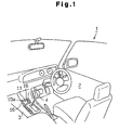
- Fig. 1 is a perspective view showing a passenger compartment 2 of a vehicle 1, in which a transceiver 11 of a remote controller 10 according to a preferred embodiment of the present invention is arranged. As shown in Fig. 1, the transceiver 11 is arranged on a center console 3 in the passenger compartment 2 of the vehicle 1.
- a recess portion 3a is formed in the forward side, with respect to the moving direction of the vehicle, of a shift lever 4 on the center console 3.
- the transceiver 11 is embedded in the recess portion 3a.
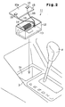
- the transceiver 11 has a generally rectangular box-like case 12.
- a control board 13 and a transmitting/receiving antenna (common antenna) 14 are accommodated in the case 12.
- the transmitting/receiving antenna 14 includes, for example, a coil antenna, such as a ferrite antenna, and receives a radio wave having a predetermined frequency (134kHz in the preferred embodiment).
- the transmitting/receiving antenna 14 is arranged near the center of the vehicle passenger compartment 2. More specifically, the transmitting/receiving antenna 14 is arranged substantially along the center line of the vehicle 1 in the vehicle passenger compartment.
- a cover 15 is mounted fitted in an opened portion of the case 12.
- Two detection switches 16 are arranged on the cover 15.
- the two detection switches 16 are connected to the control board 13 by electric wires 18.
- a portable device 31 shown in Fig. 4 is placed on the upper surface of the cover 15, which defines a mounting portion 15a.
- the two detection switches 16 are set to be on when the portable device 31 is placed on the mounting portion 15a.
- the transceiver 11 When the transceiver 11 is embedded in the recess portion 3a, the transceiver 11 is electrically connected to a battery of the vehicle 1 and other electric devices by a connector or the like (not shown).
- the case 12 is fixed to the recess portion 3a by a packing or the like.
- the transmitting circuit 21 and the receiving circuits 22, 23 are each connected to the microcomputer 24.
- the transmitting/receiving antenna 14 is connected to the transmitting circuit 21 and the receiving circuit 23 via the switching circuit 25.
- the switching circuit 25 is a circuit for selectively connecting the transmitting/receiving antenna 14 to the transmitting circuit 21 and the receiving circuit 23.
- a receiving antenna 22a is connected to the receiving circuit 22.
- the transmitting circuit 21 converts the request signal provided from the microcomputer 24 to a radio wave having a predetermined frequency and outputs the radio wave via the transmitting/receiving antenna 14.
- the transmitting circuit 21 converts the transponder driving signal provided from the microcomputer 24 to a radio wave having a predetermined frequency to generate a transponder driving radio wave and outputs the driving radio wave via the transmitting/receiving antenna 14.
- the request signal and the transponder driving radio wave are output from the transmitting/receiving antenna 14. That is, the transmitting/receiving antenna 14 serves both as an output antenna for the request signal and an output antenna for the transponder driving radio wave.
- the request signal is output in a predetermined area (a first area) A1 in the passenger compartment 2 of the vehicle and the transponder driving radio wave is output in a predetermined area (a second area) A2 near the transceiver 11. Therefore, intercommunication between the portable device 31 and the transceiver 11 in the predetermined areas A1, A2 is enabled.
- the frequencies of the request signal and the transponder driving radio wave are set to 134kHz in the preferred embodiment.
- the effective range of the output area A2 of the transponder driving radio wave is set within an area of about 0.1m from the transceiver 11 and includes the mounting portion 15a of the cover 15.
- the receiving circuit 22 receives an ID code signal from the portable device 31 via the receiving antenna 22a.
- the receiving circuit 22 demodulates the ID code signal to generate a pulse received signal and provides the pulse received signal to the microcomputer 24.
- the receiving circuit 23 receives the transponder signal from the portable device 31 via the antenna 14. In this state, the antenna 14 is connected to the receiving circuit 23 by the switching circuit 25.
- the receiving circuit 23 demodulates the transponder signal to a pulse signal to generate a received signal and provides the received signal to the microcomputer 24.
- the detection switches 16 and an engine starter 17 are connected to the microcomputer 24.
- the microcomputer 24 has a CPU unit including a CPU, a RAM and a ROM (not shown) and outputs either the request signal or the transponder driving signal.
- the microcomputer 24 When the microcomputer 24 receives the received signal including the ID code from the receiving circuit 22, the microcomputer 24 compares the preset ID code and the ID code included in the received signal (comparison of ID codes). When the two ID codes match, the microcomputer 24 provides a start permission signal to the engine starter 17.
- the microcomputer 24 When the microcomputer 24 receives the received signal including the transponder code from the receiving circuit 23, the microcomputer 24 compares the previously set transponder code and the transponder code included in the received signal (the comparison of the transponder codes). When the two transponder codes match, the microcomputer 24 supplies the start permission signal to the engine starter 17.
- the portable device 31 intercommunicates with the transceiver 11 and is carried by a driver.
- the remote controller 10 includes the portable device 31 and the transceiver 11.
- the portable device 31 includes a request signal processing circuit 30 and a transponder 35 (a transponder control section).
- the request signal processing circuit 30 includes a receiving circuit 32, a microcomputer 33 and a transmitting circuit 34.
- the receiving circuit 32 receives the request signal from the transceiver 11 via a receiving antenna 36 and provides the request signal to the microcomputer 33.
- the microcomputer 33 receives the request signal from the receiving circuit 32, the microcomputer 33 provides an ID code signal (a first signal), which includes a predetermined preset ID code, to the transmitting circuit 34.
- the transmitting circuit 34 demodulates the supplied ID code signal to a radio wave having a predetermined frequency and externally transmits the radio wave via a sending antenna 37.
- the transponder control section 35 When the transponder control section 35 obtains sufficient energy from electromagnetic waves, the transponder control section 35 outputs a transponder signal, which includes a preset predetermined transponder ID code (a transponder code). That is, when the transponder control section 35 receives the transponder driving radio wave from the transceiver 11, the transponder control section 35 outputs the transponder signal.
- the frequency of the ID code signal radio wave in the preferred embodiment is set to 300Mhz and the frequency of the transponder signal radio wave is set to 134kHz.
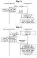
- Fig. 5 schematically shows the operation of the remote controller 10.
- the request signal is intermittently output from the transmitting/receiving antenna 14 of the transceiver 11 in the predetermined area Al.
- the request signal is constantly output when the remote controller 10 is operating.
- the portable device 31 When the portable device 31 receives the request signal in the predetermined area A1, the portable device 31 automatically transmits the ID code signal in response to the request signal. That is, when a driver carrying the portable device 31 enters the vehicle, the ID code signal is automatically transmitted from the portable device 31.
- the portable device 31 is normally set in a stand-by mode for receiving the request signal and transmits the ID code signal only when receiving the request signal.
- the transceiver 11 When receiving the ID code signal, the transceiver 11 compares the ID code included in the ID code signal with its own ID code. When the two ID codes match, the microcomputer 24 of the transceiver 11 provides the engine start permission signal to the engine starter 17.
- the engine starter 17 receives the engine start permission signal and puts the engine in a starting stand-by state. Therefore, the driver can start the engine by manipulating a predetermined engine start switch (not shown) or etc. arranged in the passenger compartment 2 of the vehicle. That is, the remote controller 10 has the functions of a smart ignition device. Therefore, the driver can start the engine without performing burdensome operations such as using the mechanical key.
- the portable device of the remote controller is driven by electric power supplied from a built-in battery (not shown). Therefore, when the battery of the portable device goes dead, the portable device cannot start the engine start through the basic operation.
- the intercommunication between the transceiver 11 and the portable device 31 enables the starting of the engine even when the battery of the portable device 31 goes dead.
- Fig. 6 schematically shows the operation of the remote controller 10 when the battery of the portable device 31 goes dead.
- the driver places the portable device 31 on the mounting portion 15a of the transceiver 11. This causes the detection switches 16 to go on and provides a detection signal to the microcomputer 24 of the transceiver 11.
- the microcomputer 24 switches the output signal of the transceiver 11 from the request signal to the transponder driving radio wave. Therefore, the transponder driving radio wave is output from the antenna 14. Then, induced electromotive force is generated in the portable device 31 by the electromagnetic induction of the transponder driving radio wave. The induced electromotive force activates the transponder control section 35, and the transponder control section 35 outputs the transponder signal.
- the transceiver 11 receives the transponder signal through the transmitting/receiving antenna 14 and compares the transponder code included in the transponder signal with its own transponder code. When the two codes match, the microcomputer 24 of the transceiver 11 provides the engine start permission signal to the engine starter 17. The engine starter 17 receives the start permission signal and puts the engine in the starting stand-by state.
- the driver may enable the starting of the engine by placing the portable device 31 on the mounting portion 15a. That is, even when the battery of the portable device 31 goes dead, the driver can start the engine without using a mechanical key.
- the remote controller 10 of the preferred embodiment has the following advantages.
- a key switch 41 may be arranged on the center console 3, and the transponder control section 35 may be provided in a mechanical key 42.
- the portable device 31 includes a portable body 31A, which incorporates the request signal processing circuit 30, and the mechanical key 42.
- the driver inserts the mechanical key 42 into the key switch 41, the transponder codes are compared.
- the mechanical key 42 starts the engine when the transponder codes match.
- the transceiver 11 does not have to be arranged on the center console 3 and may be arranged anywhere as long as it is located near the center line of the vehicle 1 in the passenger compartment 2. Further, the transceiver 11 may be arranged anywhere in the passenger compartment 2 of the vehicle such as on the driver's seat or in the instrument panel. It is desirable that the transceiver 11 be arranged near the center of the passenger compartment 2 of the vehicle (away from the door).
- the mounting portion 15a of the portable device 31 does not have to be arranged on the cover 15 and may be arranged anywhere in the output area A2 of the transponder driving radio wave. Moreover, instead of the mounting portion 15a, an insertion opening may be formed in the transceiver 11 so that when the driver inserts the portable device 31 in the insertion opening, the engine can be started by the transponder function.
- the transmitting/receiving antenna 14 may be arranged outside the case 12.
- the number of the detection switch 16 is not limited to two and may be one, three, or more than three.
- the detecting means is not limited to the detection switch 16 and may be a contact sensor, a proximity sensor, or the like.
- a smart entry function may be added to the remote controller 10. More specifically, the output level of the request signal output from the transmitting/receiving antenna 14 may be varied, and the request signal may be output in a predetermined area A3 near the vehicle 1, as shown in Fig. 3. Intercommunication between the portable device 31 and the transceiver 11 in the predetermined area A3 locks and unlocks a door. In this case, the driver may lock and unlock the door without performing any manipulations. This improves maneuverability.
Abstract
Description
- The present invention is related to a vehicle remote controller, and more particularly, to a remote controller having a portable device carried by a driver and a transceiver, which is arranged in the vehicle, to output a request signal for intercommunicating with the portable device and to output a transponder driving radio wave.
- Conventionally, cars require not only improvement in basic performance and safety but also improvement in maneuverability. Therefore, for example, a remote controller for a vehicle that remotely controls various devices arranged in the vehicle has been proposed. As an example of a vehicle remote controller, a smart ignition device has been proposed.
- The smart ignition device has a portable device carried by a driver and a transceiver arranged in the vehicle. When the driver enters the vehicle, an ID code set in the portable device, which is carried by the driver, is automatically compared to an ID code set in the transceiver, which is arranged in the vehicle. When the two ID codes match, the engine is allowed to start. Therefore, the smart ignition device causes burdensome manipulations, such as inserting a mechanical key into a key switch and rotating the key to start the engine, to become unnecessary and improves maneuverability of the vehicle. Moreover, the comparison of the ID codes improves the security level.
- The smart ignition device normally does not function when the battery of the portable device goes dead. Therefore, when the battery of the portable device goes dead, a mechanical key attached to the portable device must be used. However, the security level cannot be improved if the engine can be start by the mechanical key.
- Therefore, in the prior art, a transponder control section is arranged in the mechanical key and an antenna for outputting a transponder driving radio wave is arranged in a predetermined area in the vehicle including a key switch. When the transponder control section receives the transponder driving radio wave, the transponder control section is activated by the electromotive force induced by a received radio wave to generate a transponder signal including a predetermined transponder code. The transponder signal is transmitted to the transceiver.
- A predetermined transponder code is preset in the transceiver. When the transceiver receives the transponder signal, the transponder codes are compared. When the two transponder codes match, the transceiver permits the engine to be started by the mechanical key. This improves the security level even when the engine is started by the mechanical key.
- In the conventional smart ignition device, the request signal is output in a wide area of the vehicle. Thus, the antenna for outputting the request signal is arranged near the center of the vehicle. The antenna for outputting the transponder driving radio wave is arranged near the key switch to ensure that the transponder driving radio wave is output within a narrow area including the key switch. Therefore, the number of parts and the cost of the smart ignition device are increased by the two antennas, and the necessity for separately arranging the two antennas decreases working efficiency.
- It is an object of the present invention to provide a vehicle remote controller that decreases the number of parts.
- In one perspective of the present invention, a vehicle remote controller includes a portable device carried by a driver and a transceiver arranged in the vehicle to output a request signal for intercommunicating with the portable device and to output a transponder driving radio wave. The transceiver of the vehicle remote controller has a common antenna for transmitting the request signal and the transponder driving radio wave.
- In a further perspective of the present invention, a vehicle remote controller includes a transceiver arranged in the vehicle for generating a request signal and a transponder driving radio wave and a portable device carried by a driver, the portable device having a request signal processing circuit for receiving the request signal from the transceiver, generating a first signal based on the request signal, and transmitting the first signal to the transceiver, and a transponder for receiving the transponder driving radio wave, which generates electric power, from the transceiver, generating a transponder signal based on the transponder driving radio wave, and transmitting the transponder signal to the transceiver. The transceiver of the vehicle remote controller includes a common antenna for transmitting the request signal and the transponder driving radio wave to the portable device.
- In a further perspective of the present invention, a transceiver of a vehicle remote controller arranged in the vehicle to output a request signal, used to intercommunicate with a portable device carried by a driver, to one of a first area, which is in a vehicle passenger compartment, and an area outside the vehicle passenger compartment, and to output a transponder driving radio wave to a second area in the vehicle passenger compartment. A common antenna transmits the request signal and the transponder driving radio wave.
- In each of the above-described structures, the output antenna of the request signal is the same as the output antenna of the transponder driving signal. Therefore, the number of parts and cost of the transceiver are reduced. That is, the number of parts and cost of the vehicle remote controller is decreased.
- The invention, together with objects and advantages thereof, may best be understood by reference to the following description of the presently preferred embodiments together with the accompanying drawings in which:
- Fig. 1 is a perspective view showing a passenger compartment of a vehicle in which a transceiver of a remote controller according to a preferred embodiment of the present invention is arranged;
- Fig. 2 is a perspective view showing the transceiver of Fig. 1;
- Fig. 3 is a schematic front view of the vehicle showing output areas of a request signal and a transponder driving radio wave of the transceiver of Fig. 1;
- Fig. 4 is a schematic block diagram showing the structure of the remote controller according to the preferred embodiment of the present invention;
- Fig. 5 is a drawing showing the basic operation of the remote controller of Fig. 4;
- Fig. 6 is a drawing showing the operation of the remote controller of Fig. 4 in a transponder mode; and
- Fig. 7 is an enlarged partial perspective view showing part of a center console of the vehicle used in a further embodiment.
-
- Fig. 1 is a perspective view showing a
passenger compartment 2 of a vehicle 1, in which atransceiver 11 of aremote controller 10 according to a preferred embodiment of the present invention is arranged. As shown in Fig. 1, thetransceiver 11 is arranged on acenter console 3 in thepassenger compartment 2 of the vehicle 1. - As shown in Fig. 2, a recess portion 3a is formed in the forward side, with respect to the moving direction of the vehicle, of a
shift lever 4 on thecenter console 3. Thetransceiver 11 is embedded in the recess portion 3a. Thetransceiver 11 has a generally rectangular box-like case 12. Acontrol board 13 and a transmitting/receiving antenna (common antenna) 14 are accommodated in thecase 12. The transmitting/receivingantenna 14 includes, for example, a coil antenna, such as a ferrite antenna, and receives a radio wave having a predetermined frequency (134kHz in the preferred embodiment). The transmitting/receivingantenna 14 is arranged near the center of thevehicle passenger compartment 2. More specifically, the transmitting/receivingantenna 14 is arranged substantially along the center line of the vehicle 1 in the vehicle passenger compartment. - As shown in Fig. 2, a
cover 15 is mounted fitted in an opened portion of thecase 12. Twodetection switches 16 are arranged on thecover 15. The twodetection switches 16 are connected to thecontrol board 13 byelectric wires 18. Aportable device 31 shown in Fig. 4 is placed on the upper surface of thecover 15, which defines amounting portion 15a. The twodetection switches 16 are set to be on when theportable device 31 is placed on themounting portion 15a. - When the
transceiver 11 is embedded in the recess portion 3a, thetransceiver 11 is electrically connected to a battery of the vehicle 1 and other electric devices by a connector or the like (not shown). Thecase 12 is fixed to the recess portion 3a by a packing or the like. - A transmitting
circuit 21, receivingcircuits microcomputer 24 and aswitching circuit 25, which are shown in Fig. 4, are formed on thecontrol board 13. The transmittingcircuit 21 and thereceiving circuits microcomputer 24. The transmitting/receivingantenna 14 is connected to thetransmitting circuit 21 and thereceiving circuit 23 via theswitching circuit 25. The switchingcircuit 25 is a circuit for selectively connecting the transmitting/receivingantenna 14 to the transmittingcircuit 21 and the receivingcircuit 23. A receivingantenna 22a is connected to the receivingcircuit 22. - The transmitting
circuit 21 converts the request signal provided from themicrocomputer 24 to a radio wave having a predetermined frequency and outputs the radio wave via the transmitting/receivingantenna 14. The transmittingcircuit 21 converts the transponder driving signal provided from themicrocomputer 24 to a radio wave having a predetermined frequency to generate a transponder driving radio wave and outputs the driving radio wave via the transmitting/receivingantenna 14. The request signal and the transponder driving radio wave are output from the transmitting/receivingantenna 14. That is, the transmitting/receivingantenna 14 serves both as an output antenna for the request signal and an output antenna for the transponder driving radio wave. - As shown in Fig. 3, the request signal is output in a predetermined area (a first area) A1 in the
passenger compartment 2 of the vehicle and the transponder driving radio wave is output in a predetermined area (a second area) A2 near thetransceiver 11. Therefore, intercommunication between theportable device 31 and thetransceiver 11 in the predetermined areas A1, A2 is enabled. The frequencies of the request signal and the transponder driving radio wave are set to 134kHz in the preferred embodiment. The effective range of the output area A2 of the transponder driving radio wave is set within an area of about 0.1m from thetransceiver 11 and includes the mountingportion 15a of thecover 15. - The receiving
circuit 22 receives an ID code signal from theportable device 31 via the receivingantenna 22a. The receivingcircuit 22 demodulates the ID code signal to generate a pulse received signal and provides the pulse received signal to themicrocomputer 24. The receivingcircuit 23 receives the transponder signal from theportable device 31 via theantenna 14. In this state, theantenna 14 is connected to the receivingcircuit 23 by the switchingcircuit 25. The receivingcircuit 23 demodulates the transponder signal to a pulse signal to generate a received signal and provides the received signal to themicrocomputer 24. - The detection switches 16 and an
engine starter 17 are connected to themicrocomputer 24. Themicrocomputer 24 has a CPU unit including a CPU, a RAM and a ROM (not shown) and outputs either the request signal or the transponder driving signal. - When the
microcomputer 24 receives the received signal including the ID code from the receivingcircuit 22, themicrocomputer 24 compares the preset ID code and the ID code included in the received signal (comparison of ID codes). When the two ID codes match, themicrocomputer 24 provides a start permission signal to theengine starter 17. - When the
microcomputer 24 receives the received signal including the transponder code from the receivingcircuit 23, themicrocomputer 24 compares the previously set transponder code and the transponder code included in the received signal (the comparison of the transponder codes). When the two transponder codes match, themicrocomputer 24 supplies the start permission signal to theengine starter 17. - As shown in Fig. 4, the
portable device 31 intercommunicates with thetransceiver 11 and is carried by a driver. Theremote controller 10 includes theportable device 31 and thetransceiver 11. As shown in Fig. 4, theportable device 31 includes a requestsignal processing circuit 30 and a transponder 35 (a transponder control section). - The request
signal processing circuit 30 includes a receivingcircuit 32, amicrocomputer 33 and a transmittingcircuit 34. The receivingcircuit 32 receives the request signal from thetransceiver 11 via a receivingantenna 36 and provides the request signal to themicrocomputer 33. When themicrocomputer 33 receives the request signal from the receivingcircuit 32, themicrocomputer 33 provides an ID code signal (a first signal), which includes a predetermined preset ID code, to the transmittingcircuit 34. The transmittingcircuit 34 demodulates the supplied ID code signal to a radio wave having a predetermined frequency and externally transmits the radio wave via a sendingantenna 37. - When the
transponder control section 35 obtains sufficient energy from electromagnetic waves, thetransponder control section 35 outputs a transponder signal, which includes a preset predetermined transponder ID code (a transponder code). That is, when thetransponder control section 35 receives the transponder driving radio wave from thetransceiver 11, thetransponder control section 35 outputs the transponder signal. The frequency of the ID code signal radio wave in the preferred embodiment is set to 300Mhz and the frequency of the transponder signal radio wave is set to 134kHz. - Next, the basic operation of the
remote controller 10 will be explained. Fig. 5 schematically shows the operation of theremote controller 10. - When the
remote controller 10 is operated, the request signal is intermittently output from the transmitting/receivingantenna 14 of thetransceiver 11 in the predetermined area Al. The request signal is constantly output when theremote controller 10 is operating. - When the
portable device 31 receives the request signal in the predetermined area A1, theportable device 31 automatically transmits the ID code signal in response to the request signal. That is, when a driver carrying theportable device 31 enters the vehicle, the ID code signal is automatically transmitted from theportable device 31. Theportable device 31 is normally set in a stand-by mode for receiving the request signal and transmits the ID code signal only when receiving the request signal. - When receiving the ID code signal, the
transceiver 11 compares the ID code included in the ID code signal with its own ID code. When the two ID codes match, themicrocomputer 24 of thetransceiver 11 provides the engine start permission signal to theengine starter 17. Theengine starter 17 receives the engine start permission signal and puts the engine in a starting stand-by state. Therefore, the driver can start the engine by manipulating a predetermined engine start switch (not shown) or etc. arranged in thepassenger compartment 2 of the vehicle. That is, theremote controller 10 has the functions of a smart ignition device. Therefore, the driver can start the engine without performing burdensome operations such as using the mechanical key. - Normally, the portable device of the remote controller is driven by electric power supplied from a built-in battery (not shown). Therefore, when the battery of the portable device goes dead, the portable device cannot start the engine start through the basic operation. However, in the preferred embodiment, the intercommunication between the
transceiver 11 and theportable device 31 enables the starting of the engine even when the battery of theportable device 31 goes dead. - Hereinafter, the operation of the
remote controller 10 in the preferred embodiment when the battery of theportable device 31 goes dead will be explained. Fig. 6 schematically shows the operation of theremote controller 10 when the battery of theportable device 31 goes dead. - When the battery of the
portable device 31 goes dead, the driver places theportable device 31 on the mountingportion 15a of thetransceiver 11. This causes the detection switches 16 to go on and provides a detection signal to themicrocomputer 24 of thetransceiver 11. When receiving the detection signal, themicrocomputer 24 switches the output signal of thetransceiver 11 from the request signal to the transponder driving radio wave. Therefore, the transponder driving radio wave is output from theantenna 14. Then, induced electromotive force is generated in theportable device 31 by the electromagnetic induction of the transponder driving radio wave. The induced electromotive force activates thetransponder control section 35, and thetransponder control section 35 outputs the transponder signal. - The
transceiver 11 receives the transponder signal through the transmitting/receivingantenna 14 and compares the transponder code included in the transponder signal with its own transponder code. When the two codes match, themicrocomputer 24 of thetransceiver 11 provides the engine start permission signal to theengine starter 17. Theengine starter 17 receives the start permission signal and puts the engine in the starting stand-by state. - Therefore, in the preferred embodiment, even when the battery of the
portable device 31 goes dead, the driver may enable the starting of the engine by placing theportable device 31 on the mountingportion 15a. That is, even when the battery of theportable device 31 goes dead, the driver can start the engine without using a mechanical key. - The
remote controller 10 of the preferred embodiment has the following advantages. - (1) The transmitting/receiving
antenna 14 of thetransceiver 11 outputs the request signal and the transponder driving radio wave. That is, the output antenna of the request signal and the output antenna of the transponder driving signal are commonly used. Therefore, the number of parts of thetransceiver 11, that is, the number of parts of theremote controller 10, and costs are decreased. - (2) The transmitting/receiving
antenna 14 is near the center of the vehicle passenger compartment 2 (near the center line of the vehicle 1 in the passenger compartment 2). Therefore, the output area A1 of the request signal is larger compared to when the transmitting/receivingantenna 14 is arranged in the key switch or near a door. - (3) Generally, the reliability of the smart ignition
device increases when the request signal is not output
outside the vehicle. Thus, it is preferred that the request
signal be output only in the
vehicle passenger compartment 2. In the preferred embodiment, the transmitting/receivingantenna 14 is arranged on thecenter console 3. Therefore, the transmitting/receivingantenna 14 is located lower than the windshield or the door windows. This shields the request signal with the body of the vehicle 1 and prevents the request signal from being output from the vehicle. - (4) Even when the battery of the
portable device 31 goes dead, the driver may start the engine by placing theportable device 31 on the mountingportion 15a without using the mechanical key. -
- It should be apparent to those skilled in the art that the present invention may be embodied in many other specific forms without departing from the spirit or scope of the invention.
- As shown in Fig. 7, a
key switch 41 may be arranged on thecenter console 3, and thetransponder control section 35 may be provided in amechanical key 42. In this case, theportable device 31 includes aportable body 31A, which incorporates the requestsignal processing circuit 30, and themechanical key 42. When the driver inserts the mechanical key 42 into thekey switch 41, the transponder codes are compared. The mechanical key 42 starts the engine when the transponder codes match. - The
transceiver 11 does not have to be arranged on thecenter console 3 and may be arranged anywhere as long as it is located near the center line of the vehicle 1 in thepassenger compartment 2. Further, thetransceiver 11 may be arranged anywhere in thepassenger compartment 2 of the vehicle such as on the driver's seat or in the instrument panel. It is desirable that thetransceiver 11 be arranged near the center of thepassenger compartment 2 of the vehicle (away from the door). - The mounting
portion 15a of theportable device 31 does not have to be arranged on thecover 15 and may be arranged anywhere in the output area A2 of the transponder driving radio wave. Moreover, instead of the mountingportion 15a, an insertion opening may be formed in thetransceiver 11 so that when the driver inserts theportable device 31 in the insertion opening, the engine can be started by the transponder function. - The transmitting/receiving
antenna 14 may be arranged outside thecase 12. - The number of the
detection switch 16 is not limited to two and may be one, three, or more than three. The detecting means is not limited to thedetection switch 16 and may be a contact sensor, a proximity sensor, or the like. - A smart entry function may be added to the
remote controller 10. More specifically, the output level of the request signal output from the transmitting/receivingantenna 14 may be varied, and the request signal may be output in a predetermined area A3 near the vehicle 1, as shown in Fig. 3. Intercommunication between theportable device 31 and thetransceiver 11 in the predetermined area A3 locks and unlocks a door. In this case, the driver may lock and unlock the door without performing any manipulations. This improves maneuverability. - It should be apparent to those skilled in the art that the present invention may be embodied in many other specific forms without departing from the spirit or scope of the invention.
Claims (14)
- A vehicle remote controller including a portable device (31) carried by a driver and a transceiver (11) arranged in a vehicle to output a request signal for intercommunicating with the portable device and to output a transponder driving radio wave, the vehicle remote controller being characterized in that:the transceiver has a common antenna (14) for transmitting the request signal and the transponder driving radio wave.
- The vehicle remote controller according to claim 1, characterized in that the transceiver outputs the request signal in at least one of a first area (A1), which is in a vehicle passenger compartment, and an area outside the vehicle passenger compartment and outputs the transponder driving radio wave in a second area (A2), which is in the vehicle passenger compartment.
- The vehicle remote controller according to claim 2, characterized in that the first area (A1) in the vehicle passenger compartment is larger than the second area (A2) in the vehicle passenger compartment.
- The vehicle remote controller according to claim 2 or 3, characterized in that the antenna (14) is arranged in adjacent near a center of the vehicle.
- The vehicle remote controller according to claim 4, characterized in that the antenna (14) is arranged on a center console (3).
- The vehicle remote controller according to claim 5, characterized in that the transceiver has, within the second area of the vehicle passenger compartment, a mounting portion (15a), on which the portable device is placed, and a detecting means (16), which is arranged on the mounting portion to detect whether the portable device is placed, and when the detecting means detects that the portable device is placed on the mounting portion, the transceiver outputs the transponder driving radio wave.
- The vehicle remote controller according to claim 2, characterized in that the vehicle has a key switch (41) arranged in the second area in the vehicle for being able to start an engine, and the portable device has a mechanical key (42) and the mechanical key has a transponder (35) for receiving the transponder driving radio wave for generating electric power from the transceiver and generating a transponder signal according to the transponder driving radio wave and transmitting the transponder signal to the transceiver.
- A vehicle remote controller including a transceiver (11) arranged in a vehicle to generate a request signal and a transponder driving radio wave, and a portable device (31) carried by a driver, the portable device having a request signal processing circuit (30) for receiving the request signal from the transceiver, generating a first signal based on the request signal, and transmitting the first signal to the transceiver, and a transponder (35) for receiving the transponder driving radio wave, which generates electric power, from the transceiver, generating a transponder signal based on the transponder driving radio wave, and transmitting the transponder signal to the transceiver, the vehicle remote controller being characterized in that:the transceiver includes a common antenna (14) for transmitting the request signal and the transponder driving radio wave to the portable device.
- The vehicle remote controller according to claim 8, characterized in that the transceiver outputs the request signal to at least one of a first area (A1), which is in a vehicle passenger compartment, and an area outside the vehicle passenger compartment and outputs the transponder driving radio wave to a second area (A2) in the vehicle passenger compartment.
- The vehicle remote controller according to claim 9, characterized in that the first area (A1) in the vehicle passenger compartment is larger than the second area (A2) in the vehicle passenger compartment.
- The vehicle remote controller according to claim 9 or 10, characterized in that the antenna (14) is arranged near a center of the vehicle.
- The vehicle remote controller according to claim 11, characterized in that the antenna (14) is arranged on a center console.
- The vehicle remote controller according to claim 12, characterized in that the transceiver has, within the second area of the vehicle passenger compartment, a mounting portion, on which the portable device is placed, and a detecting means, which is arranged on the mounting portion, to detect whether the portable device is placed, and when the detecting means detects that the portable device is placed on the mounting portion, the transceiver outputs the transponder driving radio wave.
- A transceiver of a vehicle remote controller arranged in the vehicle to output a request signal, used to intercommunicate with a portable device (31) carried by a driver, to one of a first area (A1), which is in a vehicle passenger compartment, and an area outside the vehicle passenger compartment, and to output a transponder driving radio wave to a second area (A2) in the vehicle passenger compartment, the transceiver being characterized by:a common antenna (14) for transmitting the request signal and the transponder driving radio wave.
Applications Claiming Priority (3)
| Application Number | Priority Date | Filing Date | Title |
|---|---|---|---|
| JP2000125663 | 2000-04-26 | ||
| JP2000125663A JP4558136B2 (en) | 2000-04-26 | 2000-04-26 | Remote control device for vehicle |
| PCT/JP2001/003512 WO2001081133A1 (en) | 2000-04-26 | 2001-04-24 | Remote vehicle controller |
Publications (3)
| Publication Number | Publication Date |
|---|---|
| EP1201514A1 true EP1201514A1 (en) | 2002-05-02 |
| EP1201514A4 EP1201514A4 (en) | 2004-11-17 |
| EP1201514B1 EP1201514B1 (en) | 2007-02-28 |
Family
ID=18635574
Family Applications (1)
| Application Number | Title | Priority Date | Filing Date |
|---|---|---|---|
| EP01923975A Expired - Lifetime EP1201514B1 (en) | 2000-04-26 | 2001-04-24 | Remote vehicle controller |
Country Status (5)
| Country | Link |
|---|---|
| US (1) | US6958675B2 (en) |
| EP (1) | EP1201514B1 (en) |
| JP (1) | JP4558136B2 (en) |
| DE (1) | DE60126886D1 (en) |
| WO (1) | WO2001081133A1 (en) |
Cited By (6)
| Publication number | Priority date | Publication date | Assignee | Title |
|---|---|---|---|---|
| WO2003073447A2 (en) | 2002-02-28 | 2003-09-04 | Kathrein-Werke Kg | Remote-control device, particularly remote-control central lock for motor vehicles |
| EP1376481A2 (en) * | 2002-06-21 | 2004-01-02 | Kabushiki Kaisha Tokai Rika Denki Seisakusho | Electronic key system |
| EP1598246A1 (en) * | 2004-05-19 | 2005-11-23 | Kabushiki Kaisha Tokai Rika Denki Seisakusho | Controller for electronic key system |
| WO2007012363A1 (en) * | 2005-07-28 | 2007-02-01 | Huf Hülsbeck & Fürst Gmbh & Co. Kg | Ignition start switch for a motor vehicle |
| EP2192009A1 (en) * | 2008-11-26 | 2010-06-02 | Hella KG Hueck & Co. | Identifier for an electronic access system and electronic immobiliser |
| WO2015032460A1 (en) * | 2013-09-06 | 2015-03-12 | Audi Ag | Motor vehicle having a wireless key |
Families Citing this family (46)
| Publication number | Priority date | Publication date | Assignee | Title |
|---|---|---|---|---|
| JP2003085267A (en) * | 2001-09-10 | 2003-03-20 | Shin Caterpillar Mitsubishi Ltd | Body management system for working machine |
| US7107081B1 (en) | 2001-10-18 | 2006-09-12 | Iwao Fujisaki | Communication device |
| US7127271B1 (en) | 2001-10-18 | 2006-10-24 | Iwao Fujisaki | Communication device |
| US7466992B1 (en) | 2001-10-18 | 2008-12-16 | Iwao Fujisaki | Communication device |
| JP4063645B2 (en) | 2002-11-28 | 2008-03-19 | 株式会社東海理化電機製作所 | Vehicle drive control device |
| JP4084170B2 (en) | 2002-11-28 | 2008-04-30 | 株式会社東海理化電機製作所 | Vehicle drive system operating device and vehicle drive control system |
| US8229512B1 (en) | 2003-02-08 | 2012-07-24 | Iwao Fujisaki | Communication device |
| US8241128B1 (en) | 2003-04-03 | 2012-08-14 | Iwao Fujisaki | Communication device |
| JP4705317B2 (en) * | 2003-04-16 | 2011-06-22 | 株式会社東海理化電機製作所 | Switch device, security system |
| US7199710B2 (en) * | 2003-06-03 | 2007-04-03 | Kabushiki Kaisha Tokai Rika Denki | Controller for remote control system |
| JP2005034520A (en) * | 2003-07-18 | 2005-02-10 | Tokai Rika Co Ltd | Physical condition monitoring system |
| JP4195842B2 (en) | 2003-07-28 | 2008-12-17 | 株式会社東海理化電機製作所 | Engine start / stop control system |
| US8090402B1 (en) | 2003-09-26 | 2012-01-03 | Iwao Fujisaki | Communication device |
| US7917167B1 (en) | 2003-11-22 | 2011-03-29 | Iwao Fujisaki | Communication device |
| US7383056B2 (en) * | 2003-12-15 | 2008-06-03 | Fujitsu Ten Limited | Processing apparatus, portable transmitter, and remote operation system |
| JP2005186862A (en) * | 2003-12-26 | 2005-07-14 | Matsushita Electric Ind Co Ltd | Vehicular communication device |
| JP4524122B2 (en) | 2004-02-16 | 2010-08-11 | 株式会社東海理化電機製作所 | Security control system, security control device, management device in security control system, and security control method |
| JP4460911B2 (en) | 2004-02-16 | 2010-05-12 | 株式会社東海理化電機製作所 | Security control system, security control device, portable device management device, and security control method |
| JP4488343B2 (en) * | 2004-03-08 | 2010-06-23 | 朝日電装株式会社 | Passive entry system |
| US8041348B1 (en) | 2004-03-23 | 2011-10-18 | Iwao Fujisaki | Communication device |
| JP4501719B2 (en) * | 2005-02-22 | 2010-07-14 | トヨタ自動車株式会社 | Vehicle remote control device |
| US8208954B1 (en) | 2005-04-08 | 2012-06-26 | Iwao Fujisaki | Communication device |
| JPWO2006115159A1 (en) * | 2005-04-22 | 2008-12-18 | 松下電器産業株式会社 | Car |
| WO2007020821A1 (en) | 2005-08-18 | 2007-02-22 | Kabushiki Kaisha Tokai Rika Denki Seisakusho | Vehicle control device |
| JP4671348B2 (en) * | 2005-10-03 | 2011-04-13 | ヤマハ発動機株式会社 | Saddle-type vehicle with smart key system |
| JP2007107249A (en) * | 2005-10-13 | 2007-04-26 | Calsonic Kansei Corp | Mobile device for vehicle keyless apparatus |
| DE102006030642A1 (en) * | 2006-07-03 | 2008-01-10 | Conti Temic Microelectronic Gmbh | identification system |
| US20080068128A1 (en) * | 2006-08-31 | 2008-03-20 | Riad Ghabra | Keyless passive entry system |
| EP1978667B1 (en) | 2007-04-05 | 2017-10-11 | Kabushiki Kaisha Tokai Rika Denki Seisakusho | System for controlling wireless communication between portable device and communication controller |
| US7890089B1 (en) | 2007-05-03 | 2011-02-15 | Iwao Fujisaki | Communication device |
| US8559983B1 (en) | 2007-05-03 | 2013-10-15 | Iwao Fujisaki | Communication device |
| US8676273B1 (en) | 2007-08-24 | 2014-03-18 | Iwao Fujisaki | Communication device |
| JP2009097241A (en) | 2007-10-17 | 2009-05-07 | Tokai Rika Co Ltd | Security system for vehicle |
| US8639214B1 (en) | 2007-10-26 | 2014-01-28 | Iwao Fujisaki | Communication device |
| US8472935B1 (en) | 2007-10-29 | 2013-06-25 | Iwao Fujisaki | Communication device |
| US8744720B1 (en) | 2007-12-27 | 2014-06-03 | Iwao Fujisaki | Inter-vehicle middle point maintaining implementer |
| JP5021523B2 (en) * | 2008-02-26 | 2012-09-12 | 株式会社東海理化電機製作所 | Electronic key system |
| US8543157B1 (en) | 2008-05-09 | 2013-09-24 | Iwao Fujisaki | Communication device which notifies its pin-point location or geographic area in accordance with user selection |
| US8340726B1 (en) | 2008-06-30 | 2012-12-25 | Iwao Fujisaki | Communication device |
| US8452307B1 (en) | 2008-07-02 | 2013-05-28 | Iwao Fujisaki | Communication device |
| JP5222235B2 (en) * | 2009-06-24 | 2013-06-26 | 株式会社東海理化電機製作所 | In-vehicle device |
| KR101080767B1 (en) * | 2009-11-11 | 2011-11-07 | 기아자동차주식회사 | Integrated antenna module and emergency starting method for button start vehicle using the same |
| JP5123362B2 (en) * | 2010-09-13 | 2013-01-23 | ヤマハ発動機株式会社 | Saddle-type vehicle with smart key system |
| DE102016211674B4 (en) | 2016-06-29 | 2023-02-02 | Bayerische Motoren Werke Aktiengesellschaft | Vehicle with a center console and an electronic control system |
| KR101811613B1 (en) * | 2016-08-18 | 2017-12-26 | 엘지전자 주식회사 | Mobile terminal and method for controlling the same |
| JP6894345B2 (en) * | 2017-10-23 | 2021-06-30 | トヨタ自動車株式会社 | Wireless communication system |
Citations (2)
| Publication number | Priority date | Publication date | Assignee | Title |
|---|---|---|---|---|
| EP0835790A2 (en) * | 1996-10-14 | 1998-04-15 | Denso Corporation | Anti-theft device using code type transponder |
| EP0893316A1 (en) * | 1996-04-30 | 1999-01-27 | Toyota Jidosha Kabushiki Kaisha | Car theft preventive apparatus |
Family Cites Families (8)
| Publication number | Priority date | Publication date | Assignee | Title |
|---|---|---|---|---|
| JP3158010B2 (en) * | 1995-03-31 | 2001-04-23 | 富士通テン株式会社 | Vehicle identification device |
| US6140938A (en) * | 1995-04-14 | 2000-10-31 | Flick; Kenneth E. | Remote control system suitable for a vehicle and having remote transmitter verification |
| JPH1082224A (en) * | 1996-09-09 | 1998-03-31 | Tokai Rika Co Ltd | Car control system and car control method |
| JPH10273015A (en) * | 1997-03-31 | 1998-10-13 | Tokai Rika Co Ltd | Transceiver for vehicle |
| JP2970642B2 (en) | 1997-07-24 | 1999-11-02 | トヨタ自動車株式会社 | In-vehicle remote control device |
| DE19809433C1 (en) * | 1998-03-05 | 1999-06-24 | Siemens Ag | Initialisation method for motor vehicle anti-theft protection system |
| JP3983897B2 (en) * | 1998-08-05 | 2007-09-26 | 株式会社東海理化電機製作所 | Vehicle communication system |
| US6525648B1 (en) * | 1999-01-29 | 2003-02-25 | Intermec Ip Corp | Radio frequency identification systems and methods for waking up data storage devices for wireless communication |
-
2000
- 2000-04-26 JP JP2000125663A patent/JP4558136B2/en not_active Expired - Lifetime
-
2001
- 2001-04-24 EP EP01923975A patent/EP1201514B1/en not_active Expired - Lifetime
- 2001-04-24 US US10/030,319 patent/US6958675B2/en not_active Expired - Lifetime
- 2001-04-24 DE DE60126886T patent/DE60126886D1/en not_active Expired - Lifetime
- 2001-04-24 WO PCT/JP2001/003512 patent/WO2001081133A1/en active IP Right Grant
Patent Citations (2)
| Publication number | Priority date | Publication date | Assignee | Title |
|---|---|---|---|---|
| EP0893316A1 (en) * | 1996-04-30 | 1999-01-27 | Toyota Jidosha Kabushiki Kaisha | Car theft preventive apparatus |
| EP0835790A2 (en) * | 1996-10-14 | 1998-04-15 | Denso Corporation | Anti-theft device using code type transponder |
Non-Patent Citations (1)
| Title |
|---|
| See also references of WO0181133A1 * |
Cited By (13)
| Publication number | Priority date | Publication date | Assignee | Title |
|---|---|---|---|---|
| WO2003073447A2 (en) | 2002-02-28 | 2003-09-04 | Kathrein-Werke Kg | Remote-control device, particularly remote-control central lock for motor vehicles |
| WO2003073447A3 (en) * | 2002-02-28 | 2004-03-11 | Kathrein Werke Kg | Remote-control device, particularly remote-control central lock for motor vehicles |
| US7358904B2 (en) | 2002-02-28 | 2008-04-15 | Kathrein-Werke Kg | Remote-control device, particularly remote-control central lock for motor vehicles |
| EP1376481A2 (en) * | 2002-06-21 | 2004-01-02 | Kabushiki Kaisha Tokai Rika Denki Seisakusho | Electronic key system |
| EP1376481A3 (en) * | 2002-06-21 | 2005-04-13 | Kabushiki Kaisha Tokai Rika Denki Seisakusho | Electronic key system |
| US7545255B2 (en) | 2002-06-21 | 2009-06-09 | Kabushiki Kaisha Tokai Rika Denki Seisakusho | Electronic key system |
| US7193334B2 (en) | 2004-05-19 | 2007-03-20 | Kabushiki Kaisha Tokai Rika Denki Seisakusho | Controller for electronic key system |
| EP1598246A1 (en) * | 2004-05-19 | 2005-11-23 | Kabushiki Kaisha Tokai Rika Denki Seisakusho | Controller for electronic key system |
| WO2007012363A1 (en) * | 2005-07-28 | 2007-02-01 | Huf Hülsbeck & Fürst Gmbh & Co. Kg | Ignition start switch for a motor vehicle |
| DE102005035934B4 (en) | 2005-07-28 | 2020-06-04 | Huf Hülsbeck & Fürst Gmbh & Co. Kg | Ignition start switch for a motor vehicle |
| EP2192009A1 (en) * | 2008-11-26 | 2010-06-02 | Hella KG Hueck & Co. | Identifier for an electronic access system and electronic immobiliser |
| WO2015032460A1 (en) * | 2013-09-06 | 2015-03-12 | Audi Ag | Motor vehicle having a wireless key |
| US9623839B2 (en) | 2013-09-06 | 2017-04-18 | Audi Ag | Motor vehicle having a wireless key, and method for operating |
Also Published As
| Publication number | Publication date |
|---|---|
| EP1201514A4 (en) | 2004-11-17 |
| DE60126886D1 (en) | 2007-04-12 |
| EP1201514B1 (en) | 2007-02-28 |
| JP2001311333A (en) | 2001-11-09 |
| JP4558136B2 (en) | 2010-10-06 |
| US6958675B2 (en) | 2005-10-25 |
| WO2001081133A1 (en) | 2001-11-01 |
| US20020105411A1 (en) | 2002-08-08 |
Similar Documents
| Publication | Publication Date | Title |
|---|---|---|
| US6958675B2 (en) | Vehicle remote controller | |
| EP1659543B1 (en) | Security system and portable device usable therein | |
| EP1469428B2 (en) | Switch device, especially ignition switch, interrogating a transponder by radio waves | |
| US7181189B2 (en) | Vehicular remote control system and tire pressure monitoring system | |
| JP5313701B2 (en) | Vehicle door handle and locking system | |
| EP1574385B1 (en) | Passive entry system | |
| US6664899B1 (en) | Vehicular wireless control apparatus and portable unit for the same | |
| US9126564B2 (en) | Communication apparatus for vehicle | |
| US7206615B2 (en) | Vehicle communication system | |
| JP2004060191A (en) | Door handle for car | |
| US20070085657A1 (en) | Portable device for keyless entry system of motor vehicle | |
| JP2009013697A (en) | Smart keyless entry system | |
| JP3930386B2 (en) | Electronic key system | |
| JP4130368B2 (en) | Engine starter for vehicle | |
| US20040251744A1 (en) | Engine starting switch and portable device | |
| JP3216112B2 (en) | Vehicle instrumentation | |
| JP3831361B2 (en) | Operation control device of remote control system | |
| JP3462101B2 (en) | Wireless door lock control device | |
| JP3530409B2 (en) | Vehicle remote control device | |
| JP2005307742A (en) | Keyless entry device for vehicle | |
| JP2005264660A (en) | Vehicle door controller | |
| JP2004224126A (en) | Control system for vehicle | |
| JPH11125043A (en) | Keyless entry system | |
| JP2008049770A (en) | Hand-free engine starting device |
Legal Events
| Date | Code | Title | Description |
|---|---|---|---|
| PUAI | Public reference made under article 153(3) epc to a published international application that has entered the european phase |
Free format text: ORIGINAL CODE: 0009012 |
|
| 17P | Request for examination filed |
Effective date: 20020118 |
|
| AK | Designated contracting states |
Kind code of ref document: A1 Designated state(s): AT BE CH CY DE DK ES FI FR GB GR IE IT LI LU MC NL PT SE TR |
|
| RBV | Designated contracting states (corrected) |
Designated state(s): DE FR |
|
| A4 | Supplementary search report drawn up and despatched |
Effective date: 20041004 |
|
| RIC1 | Information provided on ipc code assigned before grant |
Ipc: 7B 60R 25/00 B Ipc: 7G 07C 9/00 B Ipc: 7B 60R 25/04 A |
|
| 17Q | First examination report despatched |
Effective date: 20050223 |
|
| GRAP | Despatch of communication of intention to grant a patent |
Free format text: ORIGINAL CODE: EPIDOSNIGR1 |
|
| GRAS | Grant fee paid |
Free format text: ORIGINAL CODE: EPIDOSNIGR3 |
|
| GRAA | (expected) grant |
Free format text: ORIGINAL CODE: 0009210 |
|
| AK | Designated contracting states |
Kind code of ref document: B1 Designated state(s): DE FR |
|
| REF | Corresponds to: |
Ref document number: 60126886 Country of ref document: DE Date of ref document: 20070412 Kind code of ref document: P |
|
| EN | Fr: translation not filed | ||
| PLBE | No opposition filed within time limit |
Free format text: ORIGINAL CODE: 0009261 |
|
| STAA | Information on the status of an ep patent application or granted ep patent |
Free format text: STATUS: NO OPPOSITION FILED WITHIN TIME LIMIT |
|
| PG25 | Lapsed in a contracting state [announced via postgrant information from national office to epo] |
Ref country code: DE Free format text: LAPSE BECAUSE OF FAILURE TO SUBMIT A TRANSLATION OF THE DESCRIPTION OR TO PAY THE FEE WITHIN THE PRESCRIBED TIME-LIMIT Effective date: 20070530 |
|
| 26N | No opposition filed |
Effective date: 20071129 |
|
| PG25 | Lapsed in a contracting state [announced via postgrant information from national office to epo] |
Ref country code: FR Free format text: LAPSE BECAUSE OF FAILURE TO SUBMIT A TRANSLATION OF THE DESCRIPTION OR TO PAY THE FEE WITHIN THE PRESCRIBED TIME-LIMIT Effective date: 20071019 |
|
| PG25 | Lapsed in a contracting state [announced via postgrant information from national office to epo] |
Ref country code: FR Free format text: LAPSE BECAUSE OF FAILURE TO SUBMIT A TRANSLATION OF THE DESCRIPTION OR TO PAY THE FEE WITHIN THE PRESCRIBED TIME-LIMIT Effective date: 20070228 |