EP1201449A2 - A system and method for improving the edge quality of inkjet printouts - Google Patents
A system and method for improving the edge quality of inkjet printouts Download PDFInfo
- Publication number
- EP1201449A2 EP1201449A2 EP01309026A EP01309026A EP1201449A2 EP 1201449 A2 EP1201449 A2 EP 1201449A2 EP 01309026 A EP01309026 A EP 01309026A EP 01309026 A EP01309026 A EP 01309026A EP 1201449 A2 EP1201449 A2 EP 1201449A2
- Authority
- EP
- European Patent Office
- Prior art keywords
- printhead
- correction scheme
- ink
- errors
- alignment
- Prior art date
- Legal status (The legal status is an assumption and is not a legal conclusion. Google has not performed a legal analysis and makes no representation as to the accuracy of the status listed.)
- Withdrawn
Links
Images


Classifications
-
- B—PERFORMING OPERATIONS; TRANSPORTING
- B41—PRINTING; LINING MACHINES; TYPEWRITERS; STAMPS
- B41J—TYPEWRITERS; SELECTIVE PRINTING MECHANISMS, i.e. MECHANISMS PRINTING OTHERWISE THAN FROM A FORME; CORRECTION OF TYPOGRAPHICAL ERRORS
- B41J2/00—Typewriters or selective printing mechanisms characterised by the printing or marking process for which they are designed
- B41J2/005—Typewriters or selective printing mechanisms characterised by the printing or marking process for which they are designed characterised by bringing liquid or particles selectively into contact with a printing material
- B41J2/01—Ink jet
- B41J2/015—Ink jet characterised by the jet generation process
- B41J2/04—Ink jet characterised by the jet generation process generating single droplets or particles on demand
- B41J2/045—Ink jet characterised by the jet generation process generating single droplets or particles on demand by pressure, e.g. electromechanical transducers
- B41J2/04501—Control methods or devices therefor, e.g. driver circuits, control circuits
- B41J2/04505—Control methods or devices therefor, e.g. driver circuits, control circuits aiming at correcting alignment
-
- B—PERFORMING OPERATIONS; TRANSPORTING
- B41—PRINTING; LINING MACHINES; TYPEWRITERS; STAMPS
- B41J—TYPEWRITERS; SELECTIVE PRINTING MECHANISMS, i.e. MECHANISMS PRINTING OTHERWISE THAN FROM A FORME; CORRECTION OF TYPOGRAPHICAL ERRORS
- B41J2/00—Typewriters or selective printing mechanisms characterised by the printing or marking process for which they are designed
- B41J2/005—Typewriters or selective printing mechanisms characterised by the printing or marking process for which they are designed characterised by bringing liquid or particles selectively into contact with a printing material
- B41J2/01—Ink jet
- B41J2/015—Ink jet characterised by the jet generation process
- B41J2/04—Ink jet characterised by the jet generation process generating single droplets or particles on demand
- B41J2/045—Ink jet characterised by the jet generation process generating single droplets or particles on demand by pressure, e.g. electromechanical transducers
- B41J2/04501—Control methods or devices therefor, e.g. driver circuits, control circuits
- B41J2/04573—Timing; Delays
-
- B—PERFORMING OPERATIONS; TRANSPORTING
- B41—PRINTING; LINING MACHINES; TYPEWRITERS; STAMPS
- B41J—TYPEWRITERS; SELECTIVE PRINTING MECHANISMS, i.e. MECHANISMS PRINTING OTHERWISE THAN FROM A FORME; CORRECTION OF TYPOGRAPHICAL ERRORS
- B41J2/00—Typewriters or selective printing mechanisms characterised by the printing or marking process for which they are designed
- B41J2/005—Typewriters or selective printing mechanisms characterised by the printing or marking process for which they are designed characterised by bringing liquid or particles selectively into contact with a printing material
- B41J2/01—Ink jet
- B41J2/015—Ink jet characterised by the jet generation process
- B41J2/04—Ink jet characterised by the jet generation process generating single droplets or particles on demand
- B41J2/045—Ink jet characterised by the jet generation process generating single droplets or particles on demand by pressure, e.g. electromechanical transducers
- B41J2/04501—Control methods or devices therefor, e.g. driver circuits, control circuits
- B41J2/0458—Control methods or devices therefor, e.g. driver circuits, control circuits controlling heads based on heating elements forming bubbles
-
- B—PERFORMING OPERATIONS; TRANSPORTING
- B41—PRINTING; LINING MACHINES; TYPEWRITERS; STAMPS
- B41J—TYPEWRITERS; SELECTIVE PRINTING MECHANISMS, i.e. MECHANISMS PRINTING OTHERWISE THAN FROM A FORME; CORRECTION OF TYPOGRAPHICAL ERRORS
- B41J2202/00—Embodiments of or processes related to ink-jet or thermal heads
- B41J2202/01—Embodiments of or processes related to ink-jet heads
- B41J2202/17—Readable information on the head
Definitions
- the small drops of ink are ejected from the nozzles through orifices or nozzles by rapidly heating a small volume of ink located in vaporization chambers with small electric heaters, such as small thin film resistors.
- small electric heaters such as small thin film resistors.
- the small thin film resistors are usually located adjacent the vaporization chambers. Heating the ink causes the ink to vaporize and be ejected from the orifices.
- FIG. 2 is a high level flow diagram illustrating the printhead and printing system of the present invention.
- FIG. 4 shows for illustrative purposes only a perspective view of an exemplary print cartridge incorporating the present invention.
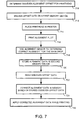
- FIG. 7 is a detailed flow diagram illustrating setup and use of the printhead of the present invention.
- the thermal head assembly 402 can be a flexible material commonly referred to as a Tape Automated Bonding (TAB) assembly and can contain a processing driver head 410 (an example of processing driver head 120 of FIG. 1) and interconnect contact pads 412.
- the interconnect contact pads 412 are suitably secured to the print cartridge 400, for example, by an adhesive material.
- the contact pads 408 align with and electrically contact electrodes (not shown) on carriage 334 of FIG. 3.
- the systematic defects can be reduced when the odd and even nozzle alignment is intentionally misaligned or offset by a predetermined amount, such as 1/600 of an inch. Text and lines printed with the predetermined amount (such as 1/600 inch offset) have cleaner edges than when printed with perfect odd/even alignment, as shown in FIG 6B. This approach works with both single pass and multipass printmodes.
- the correction scheme of the present invention can be used as an intentional offset to correct a variety of scan axis defects.
- Another example is using intentional bi-directional alignment offset to compensate for the effects of low velocity tails in bi-directional printmodes.
- FIG. 8 shows a simulated ink jet printing pattern for bi-directional print modes. The first 2 columns of dots represent one pass printing in the left-to-right and right-to-left scan directions. In each case, the main drop is followed by a low velocity tail that lands "downstream" from the main drop.
Abstract
Description
- The present invention generally relates to inkjet and other types of printers and more particularly, to a novel printing system for improving the edge quality of ink drops produced by an inkjet printer. The present invention includes a preprogrammed correction scheme that can be incorporated in an inkjet printhead for correcting systematic ink drop placement errors of the inkjet printhead.
- Inkjet printers are commonplace in the computer field. These printers are described by W.J. Lloyd and H.T. Taub in "Ink Jet Devices," Chapter 13 of Output Hardcopy Devices (Ed. R.C. Durbeck and S. Sherr, San Diego: Academic Press, 1988) and U.S. Patents 4,490,728 and 4,313,684. Inkjet printers produce high quality print, are compact and portable, and print quickly and quietly because only ink strikes a printing medium, such as paper.
- An inkjet printer produces a printed image by printing a pattern of individual dots at particular locations of an array defined for the printing medium. The locations are conveniently visualized as being small dots in a rectilinear array. The locations are sometimes "dot locations", "dot positions", or pixels". Thus, the printing operation can be viewed as the filling of a pattern of dot locations with dots of ink.
- Inkjet printers print dots by ejecting very small drops of ink onto the print medium and typically include a movable carriage that supports one or more print cartridges each having a printhead with ink ejecting nozzles. The carriage traverses over the surface of the print medium. An ink supply, such as an ink reservoir, supplies ink to the nozzles. The nozzles are controlled to eject drops of ink at appropriate times pursuant to command of a microcomputer or other controller. The timing of the application of the ink drops typically corresponds to the pattern of pixels of the image being printed.
- In general, the small drops of ink are ejected from the nozzles through orifices or nozzles by rapidly heating a small volume of ink located in vaporization chambers with small electric heaters, such as small thin film resistors. The small thin film resistors are usually located adjacent the vaporization chambers. Heating the ink causes the ink to vaporize and be ejected from the orifices.
- Specifically, for one dot of ink, a remote printhead controller, which is usually located as part of the processing electronics of the printer, activates an electrical current from an extemal power supply. The electrical current is passed through a selected thin film resistor of a selected vaporization chamber. The resistor is then heated for superheating a thin layer of ink located within the selected vaporization chamber, causing explosive vaporization, and, consequently, a droplet of ink is ejected through an associated orifice of the printhead.
- However, in many inkjet printers, defective drops, such as "tails", "spray drops" and/or "spear drops" can be ejected during the printing process, in addition to normal droplets of ink. These defective drops can cause rough edges that degrade quality and limit high resolution printing, which can compromise the inkjet printing process. One technique has been developed to improve edge quality by reducing the firing frequency at the edges of lines and text characters. This technique is effective, but requires image processing that may not be available or may be expensive and time consuming in certain situations.
- Therefore, what is needed is an inexpensive and effective printing system for improving ink drop edge quality produced by an inkjet printer. What is further needed is a preprogrammed correction scheme that can be incorporated in an inkjet printhead for correcting systematic ink drop placement errors of the inkjet printhead.
- To overcome the limitations in the prior art described above, and to overcome other limitations that will become apparent upon reading and understanding the present specification, the present invention is embodied in a printing system for improving the edge quality of ink drops produced by an inkjet printer.
- In general, the present invention can include an inkjet printhead assembly that incorporates a preprogrammed correction scheme for correcting systematic ink drop placement errors of the inkjet printhead. A general correction scheme can be developed for a class of inkjet printhead assemblies during manufacturing of the class of inkjet printhead assemblies. The correction scheme could include general corrections that cover general errors that exist for the entire class of inkjet printheads. Alternatively, individual correction schemes can be developed during manufacturing of each individual inkjet printhead assembly that covers specific errors that exists for each individual printhead.
- The correction scheme can be controlled by a printer driver as software operating on a computer system that is connected to the inkjet printer or as firmware incorporated into the printer in a controller device. Also, the correction scheme can be encoded on a memory device incorporated into inkjet printhead assembly itself. In this case, the memory device could also store other various printhead specific data. The data can include identification, warranty, characterization usage, systematic ink drop placement errors, etc. information and can be written and stored at the time the printhead assembly is manufactured or during printer operation. The correction scheme can be accessed and applied by the printer driver.
- In another embodiment, the inkjet printhead assembly includes a distributive processor that has the ability to apply the correction scheme during printing operations. The distributive processor can receive the correction scheme from the memory device or from the printer driver. The distributive processor can make other decisions, such as making its own firing and timing decisions for providing efficient thermal and energy control. For example, the distributive processor can be preprogrammed to regulate edge errors, depending on the quality of print desired by a user. In addition, the distributive processor can aid in calibrating the printhead assembly in real time.
- The printing system can also include an ink supply device having its own memory and can be fluidically coupled to the printhead assembly for selectively providing ink to the printhead assembly when necessary.
- The present invention can be further understood by reference to the following description and attached drawings that illustrate the preferred embodiment. Other features and advantages will be apparent from the following detailed description of the preferred embodiment, taken in conjunction with the accompanying drawings, which illustrate, by way of example, the principles of the invention.
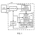
- FIG. 1 shows a block diagram of an overall printing system incorporating the present invention.
- FIG. 2 is a high level flow diagram illustrating the printhead and printing system of the present invention.
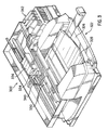
- FIG. 3 is an exemplary printer that incorporates the invention and is shown for illustrative purposes only.
- FIG. 4 shows for illustrative purposes only a perspective view of an exemplary print cartridge incorporating the present invention.
- FIG. 5 is a block diagram illustrating programming of the printhead during manufacturing, assembly and consumer use.
- FIG. 6A is an illustrative pictorial diagram showing a magnified view of ink drops ejected from a printhead.
- FIG. 6B is a comparison pictorial chart showing ink drop ejection patterns of aligned and intentionally misaligned nozzles.
- FIG. 7 is a detailed flow diagram illustrating setup and use of the printhead of the present invention.
- FIG. 8 shows a simulated ink jet printing pattern for bi-directional print modes.
- FIG. 9 shows rearranging a shingle mask for partially compensating for odd/even offset.
- In the following description of the invention, reference is made to the accompanying drawings, which form a part hereof, and in which is shown by way of illustration a specific example in which the invention may be practiced. It is to be understood that other embodiments may be utilized and structural changes may be made without departing from the scope of the present invention.
- FIG. 1A shows a block diagram of an overall printing system incorporating the present invention. The
printing system 100 can be used for printing a material, such as ink on a print media, which can be paper. The printing system can be an inkjet printer, as shown in FIG. 3. Typically, lines, text and graphics produced by an inkjet printer are usually printed with all nozzles aligned in the scan (horizontal) axis. During this type of printing operation, several systematic errors or defects can cause printed artifacts that produce rough edges that degrade quality. These systematic errors include tails, spray or spear drops. - The present invention solves the problem of artifacts produced by the systematic defects by developing specific correction schemes that compensate for the systematic defects by selectively changing printing operations, such as ink drop placement and alignment. This increases text, line and graphics quality by hiding the defects and correcting the printed artifacts to thereby reduce edge roughness caused by the systematic defects. The advantage of this invention is that it allows dramatically improved edge roughness and text quality without requiring additional image processing.
- In general, the
printing system 100 of the present invention is electrically coupled to ahost system 106, which can be a computer or microprocessor for producing print data. Theprinting system 100 includes acontroller 110 coupled to anink supply device 112, apower supply 114 and aprinthead assembly 116. Theink supply device 112 can include an inksupply memory device 118 that is fluidically coupled to theprinthead assembly 116 for selectively providing ink to theprinthead assembly 116. Theink supply device 112 can be separate from, or integrated with, theprinthead assembly 116. - The
printhead assembly 116 can also optionally include aprocessing driver head 120 and aprinthead memory device 122. Theprocessing driver head 120 is comprised of adata processor 124, such as a distributive processor, and adriver head 126, such as an array of inkjet nozzles or drop generators. - During operation of the
printing system 100, thepower supply 114 provides a controlled voltage to thecontroller 110 and theprocessing driver head 120. Also, thecontroller 110 receives the print data from the host system and processes the data into printer control information and image data. The processed data, image data and other static and dynamically generated data (discussed in detail below), is exchanged with theink supply device 112 and theprinthead assembly 116 for efficiently controlling the printing system. - The ink
supply memory device 118 can store various ink supply specific data, including ink identification data, ink characterization data, ink usage data and the like. The ink supply data can be written and stored in the inksupply memory device 118 at the time theink supply device 112 is manufactured or during operation of theprinting system 100. - Similarly, the
printhead memory device 122 can store various printhead specific data, including printhead identification data, systematic ink drop placement errors, warranty data, printhead characterization data, printhead usage data, etc. This data can be written and stored in theprinthead memory device 122 at the time theprinthead assembly 116 is manufactured or during user operation, such as user initiated calibration or testing of theprinting system 100. - The
data processor 124 can communicate withmemory devices controller 110, preferably in a bi-directional manner. The bi-directional communication enables thedata processor 124 to dynamically formulate and perform its own operations based on data received by the connected devices, either stored static data or real time dynamic data. For example, thedata processor 124 can control firing, alignment and timing operations based on sensed and given operating information for regulating the alignment of the ink drops that are ejected from the nozzles of theprocessing driver head 120. - These formulated decisions are preferably based on, among other things, previously stored information about systematic ink drop placement errors and preprogrammed correction schemes, sensed ink drop placement errors, and real time tests. As a result, the
data processor 124 enables efficient operation of theprocessing driver head 120 and produces droplets of ink that are printed on a print media to form a desired pattern for generating enhanced printed outputs. - FIG. 2 is a high level flow diagram illustrating the printhead and printing system of the present invention. The
data processor 124 of FIG. 1 can be preprogrammed to correct systematic ink drop placement errors. One such system and method for correcting the errors is shown in FIG. 2. In general, first, either during manufacturing of the printhead or during use by the end user, the system confirms that the printhead has a systematic ink drop placement error (step 210). This can be accomplished with either typical manufacturing tests during manufacturing or with printed test patterns printed by the end users. - Second, a correction scheme is developed to correct the known systematic errors (step 212). This correction scheme directly addresses the errors that exist on a given printhead with compensation operations. One example correction scheme corrects ink drop placement errors, such as alignment errors, by instructing the printhead to strategically misalign the ink drops during normal operation of the printer. This correction scheme will be discussed in detail below.
- A general correction scheme can be developed for a class of inkjet printhead assemblies during manufacturing of the class of inkjet printhead assemblies. The correction scheme could include general corrections that cover general errors that exist for the entire class of inkjet printheads. Alternatively, individual correction schemes can be developed during manufacturing of each individual inkjet printhead assembly that covers specific errors that exists for each individual printhead.
- Third, optionally, the known error (preferably as an amount) can be encoded on a memory device (such as
devices printhead 116 of FIG. 1 (step 214). Alternatively, information could be encoded directly onto a silicon die portion of the printhead and bits can be read to the die. Also, the Tape Automated Bonding (TAB) assembly ofthermal head assembly 402 of FIG. 4 could include fuseable links for the stored information. Fourth, the correction scheme is associated with (for example, a printer driver) or incorporated into theprinthead 116, optionally with eithermemory device 118 or 122 (step 216). The known error does not need to be encoded on one of the memory devices since the correction scheme preferably incorporates the known error into its corrective measures. - However, if the known error is kept separate from the correction scheme or recordation of specific errors with specific printheads are desired, the known error can be encoded into one of the memory devices. Fifth, the correction scheme is applied to the
printhead 116 during printing operations (step 218). Last, ink drops are ejected from theprinthead 116 with the correction scheme to produce smoother edges (step 220). - For example, the correction scheme can be controlled by the printer driver as software operating on a
host computer system 106 that is connected to theinkjet printer 100 or as firmware incorporated into the printer in thecontroller device 110. Also, if the correction scheme is encoded on one or both of thememory devices inkjet printhead assembly 116 itself, information can be written and stored at the time the printhead assembly is manufactured or during printer operation. The correction scheme can be accessed and applied by the printer driver. - In another embodiment, the
distributive data processor 124 has the ability to apply the correction scheme during printing operations. Thedistributive data processor 124 can receive the correction scheme from one of thememory devices distributive data processor 124 can be preprogrammed to regulate edge errors, depending on the quality of print desired by a user. In addition, thedistributive data processor 124 can aid in calibrating theprinthead assembly 116 in real time. - FIG. 3 is an exemplary high-speed printer that incorporates the invention and is shown for illustrative purposes only. Generally,
printer 300 can incorporate theprinting system 100 of FIG. 1 and further include atray 322 for holding print media. When a printing operation is initiated, print media, such as paper, is fed intoprinter 300 fromtray 322 preferably using asheet feeder 326. The sheet then brought around in a U direction and travels in an opposite direction towardoutput tray 328. Other paper paths, such as a straight paper path, can also be used. - The sheet is stopped in a
print zone 330, and ascanning carriage 334, supporting one or more printhead assemblies 336 (an example ofprinthead assembly 116 of FIG. 1), is then scanned across the sheet for printing a swath of ink thereon. After a single scan or multiple scans, the sheet is then incrementally shifted using, for example, a stepper motor and feed rollers to a next position within theprint zone 330.Carriage 334 again scans across the sheet for printing a next swath of ink. The process repeats until the entire sheet has been printed, at which point it is ejected intooutput tray 328. - The present invention is equally applicable to alternative printing systems (not shown) that utilize alternative media and/or printhead moving mechanisms, such as those incorporating grit wheel, roll feed or drum technology to support and move the print media relative to the
printhead assemblies 336. With a grit wheel design, a grit wheel and pinch roller move the media back and forth along one axis while a carriage carrying one or more printhead assemblies scans past the media along an orthogonal axis. With a drum printer design, the media is mounted to a rotating drum that is rotated along one axis while a carriage carrying one or more printhead assemblies scans past the media along an orthogonal axis. In either the drum or grit wheel designs, the scanning is typically not done in a back and forth manner as is the case for the system depicted in FIG. 3. - The
print assemblies 336 can be removeably mounted or permanently mounted to thescanning carriage 334. Also, theprinthead assemblies 336 can have self-contained ink reservoirs (for example, the reservoir can be located withinprinthead body 404 of FIG. 4) as theink supply 112 of FIG. 1. The self-contained ink reservoirs can be refilled with ink for reusing theprint assemblies 336. Alternatively, eachprint cartridge 336 can be fluidically coupled, via aflexible conduit 340, to one of a plurality of fixed orremovable ink containers 342 acting as theink supply 112 of FIG. 1. As a further alternative, the ink supplies 112 can be one or more ink containers separate or separable fromprinthead assemblies 116 and removeably mountable tocarriage 334. - FIG. 4 shows for illustrative purposes only a perspective view of an exemplary printhead assembly 400 (an example of the
printhead assembly 116 of FIG. 1) incorporating the present invention. A detailed description of the present invention follows with reference to a typical printhead assembly used with a typical printer, such asprinter 300 of FIG. 3. However, the present invention can be incorporated in any printhead and printer configuration. Referring to FIGS. 1 and 3 along with FIG. 4, theprinthead assembly 400 is comprised of a thermalinkjet head assembly 402, aprinthead body 404 and aprinthead memory device 406, which is an example ofmemory device 122. Thethermal head assembly 402 can be a flexible material commonly referred to as a Tape Automated Bonding (TAB) assembly and can contain a processing driver head 410 (an example ofprocessing driver head 120 of FIG. 1) andinterconnect contact pads 412. Theinterconnect contact pads 412 are suitably secured to theprint cartridge 400, for example, by an adhesive material. The contact pads 408 align with and electrically contact electrodes (not shown) oncarriage 334 of FIG. 3. - The
processing driver head 410 comprises a distributive processor 414 (an example of thedata processor 124 of FIG. 1) preferably integrated with a nozzle member 416 (an example ofdriver head 126 of FIG. 1). Thedistributive processor 414 preferably includes digital circuitry and communicates via electrical signals with thecontroller 110,nozzle member 416 and various analog devices, such as temperature sensors (described in detail below), which can be located on thenozzle member 416. Thedistributive processor 414 processes the signals for precisely controlling firing, correction schemes, timing, thermal and energy aspects of theprinthead assembly 400 andnozzle member 416. Thenozzle member 416 preferably contains plural orifices ornozzles 418, which can be created by, for example, laser ablation, for creating ink drop generation on a print media. - In one embodiment, as discussed above, each printhead can have a general or a specific correction scheme directly associated with the particular printhead. The general corrections would cover general errors that exist for the entire class of inkjet printheads and the specific correction schemes would cover specific errors that exists for each individual printhead.
- The following description refers to an embodiment that uses the specific correction scheme. Specific correction schemes are each associated with a particular printhead during
manufacturing 510,printhead assembly 520 and consumer use of theprinthead 530. Specifically, duringmanufacturing 510, specific offset information of systematic ink drop ejection errors are determined for each printhead (step 540) and then recorded (step 542). The specific errors can be determined with any suitable manufacturing method for determining offset or ink drop ejection errors. - During
printhead assembly 520, first a correction scheme based on the determined errors is developed (step 544). The correction scheme can be any suitable scheme that compensates for or corrects the errors. Certain schemes will be discussed below in detail. Next, for each printhead, a respective correction scheme is preprogrammed into a memory device associated with each printhead (step 546). The memory device can be any suitable memory device, such asdevices - During consumer use of the printhead, after the printhead is placed in the printer (step 548), the user has the option to correct ink drop errors or the system can automatically correct errors (step 550). If the user desires smoother lines or the system detects rough edges produced by the ink drops, the memory device is accessed during a printing operation and a correction scheme is applied to smooth the edges of the lines created by the ejected ink drops. One scheme includes intentionally misaligning the ejected ink drops based on the correction scheme to compensate for the ink drop errors (step 552), which will be discussed in detail in FIGS. 6A and 6B.
- FIG. 6A is an illustrative pictorial diagram showing a magnified view of ink drops ejected from a printhead. Typically, lines, text and graphics produced by the
inkjet printhead 400 are usually printed with allnozzles 418 of thenozzle member 416 aligned in the scan (horizontal) axis. During a high frequency printing operation, a set ofnormal drops 610 are ejected together with associated several systematicdefective drops 620, such as tails, spray or spear drops, as a pair of drops. The associated systematicdefective drops 620 can cause rough edges that degrade the quality of the printout ontomedia 630 and are unintentional drops that are ejected simultaneously with the normal drops 610. - The defective drops or spear drops 620 are usually created when certain types of printheads are fired at high frequencies, such as 36 kHz. Spear drops 620 are typically ejected at 30 m/s and have an odd/even trajectory error. The
nozzles 418 of thenozzle member 416 typically eject the spear drops 620 toward the center of thenozzle member 416 so that themedia 630 receives spattered or rough edges of lines and text printouts. A simulated printout is shown in FIG. 6B. - FIG. 6B is a comparison pictorial chart showing ink drop ejection patterns of aligned and intentionally misaligned nozzles. In general, each line simulates a vertical line produced by the
printhead 400 during firing of the ink drops at 36 kHz and using odd and even nozzles. The line on the left is an example of how the conventional method of "perfect" alignment leads to text and lines with rough edges, while the line on the right shows incorporation of the correction scheme of the present invention to reduce edge roughness. - The present invention solves the problem of systematic defects by developing specific correction schemes that compensate for the systematic defects by selectively changing printing operations, such as ink drop placement and alignment. This increases text, line and graphics quality by reducing edge roughness caused by the defects. The advantage of this invention is that it allows dramatically improved edge roughness and text quality without requiring additional image processing.
- Specifically, the ink drop pattern created on the
media 630 with odd/even nozzles aligned, without using the correction scheme of the present invention, is shown as simulated vertical line 640 (a one pass uni-directional printmode could be used to produce this pattern). As shown in FIG. 6B, although the ink drops 610 are aligned, the systematic ink drop placement errors 620 (such as the spear drops) create rough orstray edges 645 onvertical line 640. - In contrast, the ink drop pattern created using the correction scheme of FIG. 5, produces a
vertical line 650 with less stray orrough edges 655. Thisvertical line 650 can be produced with a correction scheme that intentionally misaligns the ink drops 610 to correct the systematic inkdrop placement error 620. The intentional misalignment or offset is preferably between 1/600 to 1/300 of an inch. As shown in FIG. 6B, the intentional misalignment creates avertical line 650 that incorporates the defective drops 620 into the line to reduce rough edges, thereby increasing print quality onto themedia 630. - In one working example, one method to implement the correction scheme includes first determining odd/even alignment offsets for each printhead (step 710). Second, the offset information is encoded into a first memory device (step 712), such as
memory device 122 of FIG. 1. Third, the printhead is placed into the printer (step 714). Fourth, an alignment plot is printed (step 716). Alternatively, the drop can be examined in flight. Fifth, the alignment plot is examined automatically by an alignment sensor or manually by a user to determine the correct alignment for the main ink drops (step 718). Sixth, the correct alignment data is stored in a second memory device (step 720), preferablymemory device 122. Seventh, before a printing operation, odd/even offset data is read by the printhead (step 722). Last, the correct alignment data is used to eject the ink drops during a printing operation (step 724) to intentionally misalign the ink drops. As a result, the edges of each printed line are more uniform, as shown in FIG. 6B. - The amount of offset is important when using the correction scheme of the working example. In one example, rough edges are created when certain printheads fire at 36 kHz. This is because firing at 36 kHz has been found to create systematic defects, such as the spear drops 620 of FIG. 6. The correction scheme of the present invention can be selectively disabled for printing operations that fire at less than 18kHz.
- The systematic defects can be reduced when the odd and even nozzle alignment is intentionally misaligned or offset by a predetermined amount, such as 1/600 of an inch. Text and lines printed with the predetermined amount (such as 1/600 inch offset) have cleaner edges than when printed with perfect odd/even alignment, as shown in FIG 6B. This approach works with both single pass and multipass printmodes.
- Further, the correction scheme of the present invention can be used as an intentional offset to correct a variety of scan axis defects. Another example is using intentional bi-directional alignment offset to compensate for the effects of low velocity tails in bi-directional printmodes. For example, FIG. 8 shows a simulated ink jet printing pattern for bi-directional print modes. The first 2 columns of dots represent one pass printing in the left-to-right and right-to-left scan directions. In each case, the main drop is followed by a low velocity tail that lands "downstream" from the main drop.
- The third and fourth columns represent two pass bi-directional scans formed by combining the uni-directional scans shown in the first two columns. In the third column, the rough edges caused by low velocity tails are shown when the main drops from each scan are "perfectly" aligned. The fourth column shows how an intentional bi-directional alignment offset improves edge roughness in a two pass printmode.
- The odd/even offset can be partially compensated by rearranging a typical shingle mask as shown in FIG. 9. With regard to the mask of FIG. 9, the
number 0 refers to one pass and thenumber 1 refers to the second pass. The compensated mask requires that the shingle mask be tied to the printhead (printhead based masking) instead of the print media or paper (630 of FIG. 6B). Implementing an odd/even offset to improve edge quality without increasing grain can be accomplished with the following steps: - 1) Verify that the spear drops produced by the printhead always fires in a consistent direction for odd and even nozzles;
- 2) implement an odd/even alignment offset (such as 1/600 inch) for certain print modes (usually print modes that fire drops at 36kHz);
- 3) use an odd/even compensated shingle mask (changes offset from 1/600 inch to 1/1200 inch);
- 4) use printhead-based masking for plain paper normal mode to ensure that the compensated mask is always tied to the correct nozzles;
- 5) ensure that other alignment features work correctly (bi-directional printhead-to-printhead, etc.);
- 6) encode data into memory device to enable or disable odd/even offset;
- 7) set up firmware and shingle masks so that this feature can be enabled or disabled depending on the print mode.
-
- The foregoing has described the principles, preferred embodiments and modes of operation of the present invention. However, the invention should not be construed as being limited to the particular embodiments discussed. As an example, the above-described inventions can be used in conjunction with inkjet printers that are not of the thermal type, as well as inkjet printers that are of the thermal type. Thus, the above-described embodiments should be regarded as illustrative rather than restrictive, and it should be appreciated that variations may be made in those embodiments by workers skilled in the art without departing from the scope of the present invention as defined by the following claims.
Claims (10)
- A printhead (116) comprising a processing driver head (120) having a distributive processor (124) integrated with an ink ejection driver head (126), the distributive processor (124) being preprogrammed with a correction scheme (212) that selectively prints ink drops for correcting printed artifacts.
- The printhead of claim 1, wherein the correction scheme (212) corrects systematic ink drop placement errors of the printhead.
- The printhead of claim 1, further comprising a general correction scheme (212) generated during manufacturing of a class of inkjet printheads.
- The printhead of claim 1, wherein the correction scheme (212) is generated at the time of at least one of printhead manufacturing or printhead operation.
- A method for correcting systematic printing errors of an inkjet printhead (116), comprising:determining systematic errors that are associated with the printhead (540);recording and storing the systematic errors (542);generating a correction scheme (212) to correct the systematic errors (544); andapplying the correction scheme to the printhead during printing operations to selectively print ink drops for correcting printed artifacts produced by the systematic errors (552).
- The method of claim 5, wherein the correction scheme (212) is generated as a compensation operation that corrects alignment ink drop errors by instructing the printhead (116) to strategically misalign the ink drops during normal operation of the printer (300).
- The method of claim 5, wherein determining systematic errors that are associated with the printhead (116) includes determining odd/even alignment offsets for the printhead (116).
- The method of claim 5, wherein generating a correction scheme (212) includes printing an alignment plot (716), examining the alignment plot to determine the correct alignment for main ink drops (718) and storing the correct alignment in a memory device (720), wherein examining the alignment plot includes at least one of automatically examining the plot with an alignment sensor or manually examining the plot by a user.
- The method of claim 8, further comprising, before a printing operation, reading the systematic errors (722) and using the correct alignment data (724) to eject ink drops during a printing operation (726) that are intentionally misaligned to compensate for the systematic errors.
- The method of claim 5, wherein generating a correction scheme (212) includes firing droplets and examining the droplets during flight to determine the correct alignment for main ink drops and storing the correct alignment in a memory device.
Applications Claiming Priority (2)
| Application Number | Priority Date | Filing Date | Title |
|---|---|---|---|
| US70237900A | 2000-10-31 | 2000-10-31 | |
| US702379 | 2003-11-05 |
Publications (2)
| Publication Number | Publication Date |
|---|---|
| EP1201449A2 true EP1201449A2 (en) | 2002-05-02 |
| EP1201449A3 EP1201449A3 (en) | 2003-05-14 |
Family
ID=24820986
Family Applications (1)
| Application Number | Title | Priority Date | Filing Date |
|---|---|---|---|
| EP01309026A Withdrawn EP1201449A3 (en) | 2000-10-31 | 2001-10-24 | A system and method for improving the edge quality of inkjet printouts |
Country Status (2)
| Country | Link |
|---|---|
| EP (1) | EP1201449A3 (en) |
| JP (1) | JP2002166530A (en) |
Cited By (3)
| Publication number | Priority date | Publication date | Assignee | Title |
|---|---|---|---|---|
| WO2003071780A1 (en) * | 2002-02-19 | 2003-08-28 | Polaroid Corporation | Technique for printing a color image |
| US6842186B2 (en) | 2001-05-30 | 2005-01-11 | Polaroid Corporation | High speed photo-printing apparatus |
| US8335978B2 (en) | 2008-03-26 | 2012-12-18 | Seiko Epson Corporation | Liquid container |
Families Citing this family (4)
| Publication number | Priority date | Publication date | Assignee | Title |
|---|---|---|---|---|
| US6999202B2 (en) | 2001-03-27 | 2006-02-14 | Polaroid Corporation | Method for generating a halftone of a source image |
| US6937365B2 (en) | 2001-05-30 | 2005-08-30 | Polaroid Corporation | Rendering images utilizing adaptive error diffusion |
| US7283666B2 (en) | 2003-02-27 | 2007-10-16 | Saquib Suhail S | Digital image exposure correction |
| US8773685B2 (en) | 2003-07-01 | 2014-07-08 | Intellectual Ventures I Llc | High-speed digital image printing system |
Citations (2)
| Publication number | Priority date | Publication date | Assignee | Title |
|---|---|---|---|---|
| US4313684A (en) | 1979-04-02 | 1982-02-02 | Canon Kabushiki Kaisha | Recording apparatus |
| US4490728A (en) | 1981-08-14 | 1984-12-25 | Hewlett-Packard Company | Thermal ink jet printer |
Family Cites Families (4)
| Publication number | Priority date | Publication date | Assignee | Title |
|---|---|---|---|---|
| US5661507A (en) * | 1994-02-10 | 1997-08-26 | Hewlett-Packard Company | Inkjet printing modes to optimize image-element edges for best printing quality |
| US5923344A (en) * | 1997-02-06 | 1999-07-13 | Hewlett-Packard Co. | Fractional dot column correction for scan axis alignment during printing |
| US6476928B1 (en) * | 1999-02-19 | 2002-11-05 | Hewlett-Packard Co. | System and method for controlling internal operations of a processor of an inkjet printhead |
| US6775022B2 (en) * | 1999-04-14 | 2004-08-10 | Canon Kabushiki Kaisha | Printer control based on head alignment |
-
2001
- 2001-10-24 EP EP01309026A patent/EP1201449A3/en not_active Withdrawn
- 2001-10-31 JP JP2001334775A patent/JP2002166530A/en not_active Withdrawn
Patent Citations (2)
| Publication number | Priority date | Publication date | Assignee | Title |
|---|---|---|---|---|
| US4313684A (en) | 1979-04-02 | 1982-02-02 | Canon Kabushiki Kaisha | Recording apparatus |
| US4490728A (en) | 1981-08-14 | 1984-12-25 | Hewlett-Packard Company | Thermal ink jet printer |
Cited By (5)
| Publication number | Priority date | Publication date | Assignee | Title |
|---|---|---|---|---|
| US6842186B2 (en) | 2001-05-30 | 2005-01-11 | Polaroid Corporation | High speed photo-printing apparatus |
| WO2003071780A1 (en) * | 2002-02-19 | 2003-08-28 | Polaroid Corporation | Technique for printing a color image |
| US6906736B2 (en) | 2002-02-19 | 2005-06-14 | Polaroid Corporation | Technique for printing a color image |
| US7907157B2 (en) | 2002-02-19 | 2011-03-15 | Senshin Capital, Llc | Technique for printing a color image |
| US8335978B2 (en) | 2008-03-26 | 2012-12-18 | Seiko Epson Corporation | Liquid container |
Also Published As
| Publication number | Publication date |
|---|---|
| JP2002166530A (en) | 2002-06-11 |
| EP1201449A3 (en) | 2003-05-14 |
Similar Documents
| Publication | Publication Date | Title |
|---|---|---|
| EP1314561B1 (en) | Method to correct for malfunctioning ink ejection elements in a single pass print mode | |
| US6464316B1 (en) | Bi-directional printmode for improved edge quality | |
| EP1093918B1 (en) | System and method for controlling the temperature of an inkjet printhead using dynamic pulse with adjustment | |
| JP4820045B2 (en) | Inkjet printhead having four staggered rows of nozzles | |
| US6309052B1 (en) | High thermal efficiency ink jet printhead | |
| US6464334B2 (en) | Method for improving the quality of printing processes involving black pixel depletion | |
| JP2001191538A (en) | Easy-to-make printer and process for embodiment | |
| JP2000071432A (en) | Method and device for compensating troubled ink jet nozzle | |
| US6270201B1 (en) | Ink jet drop generator and ink composition printing system for producing low ink drop weight with high frequency operation | |
| US7014295B2 (en) | System and method for producing efficient ink drop overlap filled with a pseudo hexagonal grid pattern | |
| EP1201449A2 (en) | A system and method for improving the edge quality of inkjet printouts | |
| EP1270225B1 (en) | A system and method for using lower data rates for printheads with closely spaced nozzles | |
| US6481823B1 (en) | Method for using highly energetic droplet firing events to improve droplet ejection reliability | |
| US6619794B2 (en) | System and method for optimizing ink drying time through multiple spaced printheads | |
| US6328413B1 (en) | Inkjet printer spitting method for reducing print cartridge cross-contamination | |
| US6367913B1 (en) | System and method for improving the lightfastness of color printouts | |
| US20020180830A1 (en) | Print direction dependent firing frequency for improved edge quality | |
| JP2006110890A (en) | Inkjet recorder and method of controlling the same |
Legal Events
| Date | Code | Title | Description |
|---|---|---|---|
| PUAI | Public reference made under article 153(3) epc to a published international application that has entered the european phase |
Free format text: ORIGINAL CODE: 0009012 |
|
| AK | Designated contracting states |
Kind code of ref document: A2 Designated state(s): AT BE CH CY DE DK ES FI FR GB GR IE IT LI LU MC NL PT SE TR |
|
| AX | Request for extension of the european patent |
Free format text: AL;LT;LV;MK;RO;SI |
|
| PUAL | Search report despatched |
Free format text: ORIGINAL CODE: 0009013 |
|
| AK | Designated contracting states |
Designated state(s): AT BE CH CY DE DK ES FI FR GB GR IE IT LI LU MC NL PT SE TR |
|
| AX | Request for extension of the european patent |
Extension state: AL LT LV MK RO SI |
|
| RIC1 | Information provided on ipc code assigned before grant |
Ipc: 7B 41J 2/05 A |
|
| 17P | Request for examination filed |
Effective date: 20030717 |
|
| AKX | Designation fees paid |
Designated state(s): DE FR GB |
|
| 17Q | First examination report despatched |
Effective date: 20050902 |
|
| STAA | Information on the status of an ep patent application or granted ep patent |
Free format text: STATUS: THE APPLICATION IS DEEMED TO BE WITHDRAWN |
|
| 18D | Application deemed to be withdrawn |
Effective date: 20070321 |