EP1198122A2 - System and method for interfacing with multiple production scanners - Google Patents
System and method for interfacing with multiple production scanners Download PDFInfo
- Publication number
- EP1198122A2 EP1198122A2 EP01123264A EP01123264A EP1198122A2 EP 1198122 A2 EP1198122 A2 EP 1198122A2 EP 01123264 A EP01123264 A EP 01123264A EP 01123264 A EP01123264 A EP 01123264A EP 1198122 A2 EP1198122 A2 EP 1198122A2
- Authority
- EP
- European Patent Office
- Prior art keywords
- module
- scanner
- commands
- application program
- image data
- Prior art date
- Legal status (The legal status is an assumption and is not a legal conclusion. Google has not performed a legal analysis and makes no representation as to the accuracy of the status listed.)
- Withdrawn
Links
- 238000000034 method Methods 0.000 title claims abstract description 43
- 238000004519 manufacturing process Methods 0.000 title abstract description 54
- 230000006854 communication Effects 0.000 claims abstract description 12
- 238000004891 communication Methods 0.000 claims abstract description 12
- 238000003860 storage Methods 0.000 claims description 17
- 230000000977 initiatory effect Effects 0.000 claims description 4
- 238000003384 imaging method Methods 0.000 claims 2
- 238000002360 preparation method Methods 0.000 description 50
- 230000008569 process Effects 0.000 description 19
- ABEXEQSGABRUHS-UHFFFAOYSA-N 16-methylheptadecyl 16-methylheptadecanoate Chemical compound CC(C)CCCCCCCCCCCCCCCOC(=O)CCCCCCCCCCCCCCC(C)C ABEXEQSGABRUHS-UHFFFAOYSA-N 0.000 description 14
- 241000764238 Isis Species 0.000 description 14
- 238000005417 image-selected in vivo spectroscopy Methods 0.000 description 14
- 238000012739 integrated shape imaging system Methods 0.000 description 14
- 238000007639 printing Methods 0.000 description 12
- 238000010586 diagram Methods 0.000 description 8
- 238000012545 processing Methods 0.000 description 8
- 230000006870 function Effects 0.000 description 7
- 238000007726 management method Methods 0.000 description 7
- 238000013459 approach Methods 0.000 description 5
- 239000011230 binding agent Substances 0.000 description 4
- 238000012546 transfer Methods 0.000 description 4
- 238000006243 chemical reaction Methods 0.000 description 3
- 238000012937 correction Methods 0.000 description 3
- 230000002250 progressing effect Effects 0.000 description 3
- 230000004075 alteration Effects 0.000 description 2
- 230000015556 catabolic process Effects 0.000 description 2
- 230000001427 coherent effect Effects 0.000 description 2
- 238000006731 degradation reaction Methods 0.000 description 2
- 238000002716 delivery method Methods 0.000 description 2
- 238000001514 detection method Methods 0.000 description 2
- 238000011161 development Methods 0.000 description 2
- 239000000428 dust Substances 0.000 description 2
- 239000011521 glass Substances 0.000 description 2
- 230000003993 interaction Effects 0.000 description 2
- 238000012549 training Methods 0.000 description 2
- KKIMDKMETPPURN-UHFFFAOYSA-N 1-(3-(trifluoromethyl)phenyl)piperazine Chemical compound FC(F)(F)C1=CC=CC(N2CCNCC2)=C1 KKIMDKMETPPURN-UHFFFAOYSA-N 0.000 description 1
- 241000272878 Apodiformes Species 0.000 description 1
- 230000007175 bidirectional communication Effects 0.000 description 1
- 230000001010 compromised effect Effects 0.000 description 1
- 238000004883 computer application Methods 0.000 description 1
- 238000004590 computer program Methods 0.000 description 1
- 230000000593 degrading effect Effects 0.000 description 1
- 230000003111 delayed effect Effects 0.000 description 1
- 238000005516 engineering process Methods 0.000 description 1
- 239000000835 fiber Substances 0.000 description 1
- 230000007257 malfunction Effects 0.000 description 1
- 230000000873 masking effect Effects 0.000 description 1
- 238000012986 modification Methods 0.000 description 1
- 230000004048 modification Effects 0.000 description 1
- 238000007781 pre-processing Methods 0.000 description 1
- 230000035755 proliferation Effects 0.000 description 1
- 238000011084 recovery Methods 0.000 description 1
- 230000004043 responsiveness Effects 0.000 description 1
- 230000002441 reversible effect Effects 0.000 description 1
- 238000013518 transcription Methods 0.000 description 1
- 230000035897 transcription Effects 0.000 description 1
- 238000013519 translation Methods 0.000 description 1
- 230000014616 translation Effects 0.000 description 1
- 230000000007 visual effect Effects 0.000 description 1
- 238000012800 visualization Methods 0.000 description 1
Images


Classifications
-
- H—ELECTRICITY
- H04—ELECTRIC COMMUNICATION TECHNIQUE
- H04N—PICTORIAL COMMUNICATION, e.g. TELEVISION
- H04N1/00—Scanning, transmission or reproduction of documents or the like, e.g. facsimile transmission; Details thereof
- H04N1/00127—Connection or combination of a still picture apparatus with another apparatus, e.g. for storage, processing or transmission of still picture signals or of information associated with a still picture
- H04N1/00204—Connection or combination of a still picture apparatus with another apparatus, e.g. for storage, processing or transmission of still picture signals or of information associated with a still picture with a digital computer or a digital computer system, e.g. an internet server
- H04N1/00236—Connection or combination of a still picture apparatus with another apparatus, e.g. for storage, processing or transmission of still picture signals or of information associated with a still picture with a digital computer or a digital computer system, e.g. an internet server using an image reading or reproducing device, e.g. a facsimile reader or printer, as a local input to or local output from a computer
- H04N1/00241—Connection or combination of a still picture apparatus with another apparatus, e.g. for storage, processing or transmission of still picture signals or of information associated with a still picture with a digital computer or a digital computer system, e.g. an internet server using an image reading or reproducing device, e.g. a facsimile reader or printer, as a local input to or local output from a computer using an image reading device as a local input to a computer
-
- H—ELECTRICITY
- H04—ELECTRIC COMMUNICATION TECHNIQUE
- H04N—PICTORIAL COMMUNICATION, e.g. TELEVISION
- H04N1/00—Scanning, transmission or reproduction of documents or the like, e.g. facsimile transmission; Details thereof
- H04N1/00912—Arrangements for controlling a still picture apparatus or components thereof not otherwise provided for
- H04N1/0096—Simultaneous or quasi-simultaneous functioning of a plurality of operations
-
- H—ELECTRICITY
- H04—ELECTRIC COMMUNICATION TECHNIQUE
- H04N—PICTORIAL COMMUNICATION, e.g. TELEVISION
- H04N1/00—Scanning, transmission or reproduction of documents or the like, e.g. facsimile transmission; Details thereof
- H04N1/32—Circuits or arrangements for control or supervision between transmitter and receiver or between image input and image output device, e.g. between a still-image camera and its memory or between a still-image camera and a printer device
- H04N1/32502—Circuits or arrangements for control or supervision between transmitter and receiver or between image input and image output device, e.g. between a still-image camera and its memory or between a still-image camera and a printer device in systems having a plurality of input or output devices
- H04N1/32507—Circuits or arrangements for control or supervision between transmitter and receiver or between image input and image output device, e.g. between a still-image camera and its memory or between a still-image camera and a printer device in systems having a plurality of input or output devices a plurality of input devices
- H04N1/32512—Circuits or arrangements for control or supervision between transmitter and receiver or between image input and image output device, e.g. between a still-image camera and its memory or between a still-image camera and a printer device in systems having a plurality of input or output devices a plurality of input devices of different type, e.g. internal and external devices
-
- H—ELECTRICITY
- H04—ELECTRIC COMMUNICATION TECHNIQUE
- H04N—PICTORIAL COMMUNICATION, e.g. TELEVISION
- H04N1/00—Scanning, transmission or reproduction of documents or the like, e.g. facsimile transmission; Details thereof
- H04N1/00127—Connection or combination of a still picture apparatus with another apparatus, e.g. for storage, processing or transmission of still picture signals or of information associated with a still picture
- H04N1/00204—Connection or combination of a still picture apparatus with another apparatus, e.g. for storage, processing or transmission of still picture signals or of information associated with a still picture with a digital computer or a digital computer system, e.g. an internet server
- H04N1/00236—Connection or combination of a still picture apparatus with another apparatus, e.g. for storage, processing or transmission of still picture signals or of information associated with a still picture with a digital computer or a digital computer system, e.g. an internet server using an image reading or reproducing device, e.g. a facsimile reader or printer, as a local input to or local output from a computer
-
- H—ELECTRICITY
- H04—ELECTRIC COMMUNICATION TECHNIQUE
- H04N—PICTORIAL COMMUNICATION, e.g. TELEVISION
- H04N2201/00—Indexing scheme relating to scanning, transmission or reproduction of documents or the like, and to details thereof
- H04N2201/0008—Connection or combination of a still picture apparatus with another apparatus
- H04N2201/0074—Arrangements for the control of a still picture apparatus by the connected apparatus
-
- H—ELECTRICITY
- H04—ELECTRIC COMMUNICATION TECHNIQUE
- H04N—PICTORIAL COMMUNICATION, e.g. TELEVISION
- H04N2201/00—Indexing scheme relating to scanning, transmission or reproduction of documents or the like, and to details thereof
- H04N2201/0077—Types of the still picture apparatus
- H04N2201/0081—Image reader
-
- H—ELECTRICITY
- H04—ELECTRIC COMMUNICATION TECHNIQUE
- H04N—PICTORIAL COMMUNICATION, e.g. TELEVISION
- H04N2201/00—Indexing scheme relating to scanning, transmission or reproduction of documents or the like, and to details thereof
- H04N2201/0077—Types of the still picture apparatus
- H04N2201/0082—Image hardcopy reproducer
Definitions
- a production printer is a printing device capable of rapid production of large volumes of documents. Typically these printers have high paper handling capacity, the ability to draw on multiple media types from multiple sources and the ability to automatically finish a document such as by adding a binding.
- production printing is still a complicated and often manual process.
- a finished product such as a bound booklet, a tri-fold brochure or a tabbed three ring bound notebook.
- a finished product such as a bound booklet, a tri-fold brochure or a tabbed three ring bound notebook.
- the combination of the original documents plus the instructions for producing the finished product is called a "job".
- the documents can be brought in either in hard copy or electronic form, such as on floppy disk, compact disc or tape or can be transmitted to the print shop over a network such as the Internet.
- Documents which are delivered in a hard copy form to the print ship must first be scanned into the shop's computer system so that they can be edited and otherwise prepared for production.
- the shop will have a one or more scanning stations consisting of one or more workstation computers coupled with one or more production scanners.
- production scanners are high volume devices which are capable of scanning a high volume of originals continuously at high speed and at high resolution. While scanners tend to be very accurate and reliable devices, scanning documents can still be very resource intensive especially coupled with the high volume and high speed environment of a production print shop.
- the operator will load a document into the scanner's automated feeder.
- the operator will load the scanning application into the workstation, if not already loaded, and then instruct the scanner to scan the document.
- the operator can view the scanned document and verify that a faithful reproduction was made.
- errors include operator errors or scanner malfunctions such as dust on the scanning glass, paper mis-feeds or lamp failures.
- the parameters of the scan such as the image processing algorithms, contrast or color balance, need to be adjusted to account for the characteristics of the original document. These adjustments may not be apparent from a visual examination of the original document and may require several re-scans to get the parameters set correctly. For large documents, such rescanning can be time consuming and costly.
- the present invention is defined by the following claims, and nothing in this section should be taken as a limitation on those claims.
- the first application program is operative to transmit first and second commands to the first and second scanners and the first and second scanners are operative to scan first and second documents and transmit first and second image data and first and second status data from the scans to the first application program.
- the driver comprises an application program interface (“API") coupled with the first application program and operative to receive the first commands from the first application program.
- API application program interface
- the driver further comprises a first scanner personality module (“SPM”) coupled with the API and the first scanner and operative to receive the first image data and the first status data from the first scanner and transmit the first commands to the first scanner and provide the first image data and the first status data to the first application program and a second scanner personality module (“SPM") coupled with the API and the second scanner and operative to receive the second image data and the second status data from the second scanner and transmit the second commands to the second scanner and provide the second image data and the second status data to the first application program and wherein the second SPM is further capable of operating substantially simultaneously with the first SPM.
- the API and the first and second SPM's facilitate real time communication between the first application program and the first and second scanners.
- the preferred embodiments further relate to a method of interfacing a first application program to first and second scanners, the first application program executing on a first computer coupled with the first and second scanners.
- the method comprises: initiating a first scan of a first document on the first scanner as directed by the first application program; initiating a second scan of a second document on the second scanner as directed by the first application program, as the first scan progresses; receiving first image data generated by the first scan as the first and second scans progress; receiving first status data from the first scanner as the first and second scans progress; receiving second image data generated by the second scan as the first and second scans progress; receiving second status data from the second scanner as the first and second scans progress; providing the first image data and the first status data to the first application program as the first and second scans progress; providing the second image data and the second status data to the first application program as the first and second scans progress; adjusting the first scan as the first and second scans progress; and adjusting the second scan as the first and second scans progress.
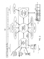
- FIG. 1 there is shown a flow diagram illustrating the production work flow 100 in a typical production print shop such as a commercial high volume copy or print shop.
- a workflow is defined as the tasks, procedural steps, organizations or people involved, required input and output information, and tools needed for each step in a business process.
- a workflow approach to analyzing and managing a business or process such as production printing can be combined with an object oriented approach, which tends to focus on the discrete objects and processes involved such as documents, pages, data and databases.
- object oriented when applied to the disclosed embodiments, does not imply that an object oriented programming approach is the only method of implementation of the disclosed embodiments.
- Figure 1 further depicts a typical computer network 112 for use in a print shop.
- a network 112 of computer work stations 114, 116, servers 118, 120, high volume input device 124, and high volume output devices 122 which make up the computer network 112.
- the servers 118, 120 include network servers 118 and print servers 120.
- the topology of the network 112 is typically structured so as to align with the workflow 100 of the print shop.
- the network 112 may be implemented as a wired or wireless Ethernet network or other form or local area network. Further the network 112 may include wired or wireless connections to wide area networks such as the Internet and connections to other local area networks such as through a virtual private network.
- the production workflow 100 includes the procedural stages of job origination 102, job submission 104, job preparation 106, print production 108 and final fulfillment 110. Alternatively, one or more of these procedural stages may be combined as well as there may be other additional procedural stages.
- Job origination 102 is the procedural stage of receiving the documents and instructions, which together are defined as a "job", from the customer. Job origination 102 can occur when a customer physically brings his job, whether in hard copy or electronic form, to the print shop or otherwise transmits the job to the print shop, whether by phone, fax, postal mail, electronic mail or over a local area or wide area network such as over the Internet. Note that a job may contain more than one document and more than one set of instructions.
- a job may contain many documents, each being one chapter of a book, along with a document containing a cover for the book.
- This exemplary job may include the instructions for producing the body of the book from the individual chapter documents and another set of instructions for producing the cover.
- Job submission 104 is the receipt of the job by the print shop and the entering of the job into the print shops production system or workflow.
- the instructions from the customer will be written down on a special form, known as a "ticket” or "job ticket”.
- a ticket may also be electronically created and maintained.
- pre-defined tickets may be available for standardized instructions.
- the shop may have a pad of pre-printed tickets with the instructions to duplicate the documents, three hole punch the final output and assemble the punched final output in a three ring binder. If this is a common request by customers, such pre-printed tickets can save time and resources. All the order taking clerk need do is fill in any customer specific details such as the number of copies to produce.
- Pre-defined tickets may help to standardize operations and prevent errors in the transcription of instructions from the customer.
- job submission 104 may simply be the receiving of the original documents and instructions along with the creation of a ticket, placing the job in a paper folder and setting it in a physical queue for later handling in subsequent procedural stages.
- job submission 104 requires entering the job into the shops electronic production system.
- the documents For documents which are brought in by the customer as hard copy, the documents must first be scanned electronically into the shop's computer system.
- the document data files For documents delivered in electronic form, the document data files must be loaded on the shop's computer system.
- the computer network 112 will include one or more "store front" workstations 114.
- the store front workstations 114 are computer systems placed at the order taking desk, at a manned clerk's station or set out for customer self service use. These workstations 114 are used for the job submission stage 104 and typically will be configured to handle many different electronic media types such as floppy disk, compact disc, tape, etc. These stations 114 may also be configured to receive jobs over the Internet or other form of network connection with customers. Further, these workstations 114 are typically configured to read many different electronic file formats such as those used by the Microsoft OfficeTM family of products manufactured by Microsoft Corporation, located in Redmond, Washington or various other desktop publishing program file formats such as Aldus PagemakerTM or QuarkXpressTM.
- stations 114 can also read "ready for printer” file formats, which will be discussed later, such as Portable Document FormatTM (“PDF”), PostscriptTM (“PS”) or printer control language (“PCL”).
- Job preparation workstations 116 can also accept image formats such as Tagged Image File Format (“TIFF”), bitmap (“BMP”) and PCX.
- TIFF Tagged Image File Format
- BMP bitmap
- PCX PCX
- stations 114 may also include a scanner 124 for scanning hard copies of documents into the computer system. Scanners typically are complicated devices to operate and some print shops may prefer to locate the scanners 124 in the job preparation stage 106 coupled with the job preparation workstations 116 (as shown in the figure) for use solely by trained personnel as will be discussed below.
- the store front computers 114 also provide the ability to generate a ticket, electronically or in hard copy form, for the job containing all of the instructions for completing the production printing task. This process of generating the ticket may be automated, involving pre-defined tickets, manual or a combination thereof.
- Job preparation 106 involves preparing the documents for printing according to the instructions in the ticket.
- job preparation 106 may include scanning the documents and creating a faithful and error free electronic reproduction.
- the documents, once in electronic form, must also be distilled down or converted into a common file format that the print shop can use to both edit and print the documents. This alleviates the need for operators to deal with multiple different programs and eliminates the need to assemble complex documents together for printing using different electronic file formats.
- a customer may bring in two different documents, one being the body of a book and the other being the photographs to be inserted at specific pages. The customer may then instruct that the photographs be inserted at particular pages and that the final assembly have continuous page numbers added.
- the body of the book may be in Microsoft WordTM format while the images of the photographs are in Adobe PhotoshopTM format. While the operator could figure out at which pages the images will be inserted and appropriately number the pages of the book and photographs using each individual software package, this is a very complex and time consuming process. It also requires that the operator be trained and familiar with a range of software packages and runs the risk that he will not be familiar with the particular package that the customer used.
- a ready for printer file format is defined as a file format which contains both the data to be printed along with printer control instructions that can be directly interpreted by the internal processing engine of a printer or other form of hard copy output device in order to rasterize the data image onto the output media. Rasterization is the placement of image data at a specific location on the output media.
- file formats include Portable Document FormatTM ("PDF”) and PostscriptTM ("PS”) both manufactured by Adobe Systems, Inc., located in San Jose, California, as well as printer control language (“PCL”), manufactured by Hewlett Packard, located in Palo Alto, California.
- PDF Portable Document FormatTM
- PS PostscriptTM
- PCL printer control language
- Examples of non-ready for printer formats include the native application file formats for personal computer application programs such as Microsoft WordTM. These file formats must be first converted to a ready for printer file format before they can be printed.
- image file formats such as the Tagged Image File Format ("TIFF") contain bit image data only which is already in a format which specifies its output location on the output media and does not contain printer control instructions for interpretation by the internal processing engine of the printer and therefore, for the purposes of this disclosure, is not a ready for printer file format.
- TIFF Tagged Image File Format
- rasterization of the image data can be delayed as close as possible to the final placement of the image data on the output media. This allows the most efficient use of the production print device 122 by allowing its internal control logic to optimize the rasterization process resulting in output that is more likely to match with the operator's expectations.
- the computer network 106 includes job preparation workstations 116, scanners 124 and network servers 118 coupled with the store front workstations 114 over the network 112.
- the phrase "coupled with” is defined to mean directly connected to or indirectly connected with through one or more intermediate components.
- Such intermediate components may include both hardware and software based components.
- the job preparation workstations 116 preferably execute workflow management software which allows the operator to manage, edit and print jobs.
- the network server(s) 118 includes a document library which allows manipulation, management, storage and archiving of jobs, or just there respective documents and/or tickets, as well as facilitates and manages the flow of jobs from the store front computers 114 to the job preparation workstations 116 and from the job preparation workstations 116 to the print servers 120 or the production output devices 122.
- Exemplary document libraries include Intra.DocTM document management system manufactured by Intranet Solutions, Inc., located in Eden Prairie, Minnesota and the DOCFusion document management system manufactured by Hummingbird, Inc., located in York, Ontario, Canada.
- the job preparation workstations 116 are ImagesmartTM Workstations, manufactured by Heidelberg Digital, L.L.C., located in Rochester, New York.
- the network servers 118 preferably comply with the Open Document Management Architecture ("ODMA") standard and provide document management capabilities and scaleable storage.
- ODMA Open Document Management Architecture
- the job preparation workstations 116 also provide the capability of the print shop to add value to the print production process by offering services to the customer. Such services include the ability to modify documents provided by the customer to add features that the customer could not or would not add himself. Such features include adding page numbers across multiple documents, bates numbering, adjusting page layout for tab stock and aligning the output to account for binding. Further the job preparation workstations 116 provide the capability to fix errors in the documents such as removing artifacts in scanned images and masking over unwanted text or markings. The job preparation workstations 116 can also be used to prevent inaccuracies in the finished output caused by the printing or binding process.
- Binder's creep occurs when the placement of the images on the paper fails to account for the thickness of the binding as a function of the number of pages in the book causing the image on the pages to shift inward as you get closer to the cover. Binder's creep is prevented by shifting image slightly when performing the signature imposition on the document.
- the job preparation workstation 116 allows the operator to manage and layout the document pages for final output, also known as "imposition” and "signature imposition".
- the operator can shuffle pages, reverse pages, insert blank pages, trim and shift pages, create bleeds and place multiple pages on a sheet, also known as "n-up" to create proof sets, brochures or pamphlets, etc.
- job preparation workstation 116 permits the operator to add annotations to the document such as bates numbers, page numbers, logos and watermarks. All of these service add value to the final output. Formatting and other modifications to the document can be globally applied to the entire document, such as a shifted margin or may be applied only to select pages. Such alterations to the document are known as document/page features or attributes. Further, these alterations are also known as document or page exceptions since they typically override specific instances of the original document formatting as set by the customer.
- the print production stage 108 The next stage in the print production workflow 100 is the print production stage 108.
- the print production stage 108 the final form of the documents for printing is sent to a print server 120 which will distribute the job to the final output device 122.
- this stage 108 would be similar to an operator manually taking the ready for production job over to the desired output device 122 to start the job.
- the print production stage 108 manages the output resources of the print shop. Such management includes queuing jobs to the proper devices 122 in the shop, routing jobs to available devices 122, balancing the load placed on the various devices 122, and pre-processing jobs, such as splitting or RIP'ing the job, prior to sending it to a particular device 122.
- RIP stands for Raster Image Processor and is the hardware and/or software which converts ready for printer data into raster images. It is also a common term for rasterizing a page image on to the output media.
- the print server 120 used in the print production stage 108 is coupled with the job preparation workstations 116 and the network server 118 over the network 112. Further, the print server 120 is coupled with the various output devices 122 in the print shop. Note that some output devices 122 may not support electronic transfer of the data to be output and may require a manual step for operation. Such devices may include a special binding machine which requires that the partially finished documents be manually transferred to the binding machine to complete the production.
- the print server 120 is preferably implemented as a separate computer coupled with the network 112, however, software based print servers running on a network server 118, job preparation workstation 116 or store front workstation 114 may also be used.
- the printer server 120 includes an independent computer workstation, typically running a UNIX or Windows NT operating system, a software print server engine and a software print server application.
- the print server application offers the user interface ability to configure and manage the print server operation.
- the print server engine performs the automated processes of the print server. These processes include spooling and queuing jobs and job content (i.e. the document), directing the jobs to specific production output devices based on the attributes of the print job and how these attributes are satisfied by the print engine, load balancing jobs among the various production output devices to keep all printers fully utilized, e.g. to split color from black and white jobs, and acting as a communication gateway where it can accept multiple input communication and print protocols translating them to the communication and print protocol the production output device 122 understands.
- the final stage of the production printing workflow 100 is the final fulfillment stage 110.
- the final fulfillment stage 110 is the stage where the finished output is produced on the production output device 122.
- a production output device is a computer output device, such as a printer, designed for high volume production of printed documents. Such devices preferably include the ability to produce large quantities of documents with mixed media types and various degrees of finishing, such as stapling or binding, at very high speed. Exemplary output devices include the DigimasterTM Digital High Volume Printer manufactured by Heidelberg Digital, L.L.C., located in Rochester, New York. and the NexPressTM Color printer manufactured by NexPress, Corporation, located in Rochester, New York.
- the user workflow 200 includes an input source stage 202, a preflight stage 204 and a production stage 206.
- the input source stage 202 all of the documents of the job are collected together from the different input sources 208.
- all of the collected documents are converted to a ready for printer format, preferably a Portable Document FormatTM.
- This conversion can be a manual or automated process or a combination thereof.
- a special directory can be created on the network server 118 where data files in various file formats can be placed, for example, by the clerk who accepts the documents from the customer and inputs them into the store front workstation 114.
- this process may include a manual or automated determination of the capabilities, skill level or training level of the various operators currently logged into the available job preparation workstations 116 as well as the current load/backlog of job in their respective queues. Taking these factors into account, job can be automatically or manually routed to the operator best able to handle the job both technically and in an expedient manner.
- This functionality can be implemented by creating an operator database which tracks the capabilities, skill level and training level of the various operators who work in the print shop. This database can be coupled with queue management software which balances the loads/backlogs of job at each station 116.
- the documents can be assembled, such as in a book, annotated, edited, and have imposition or other page features applied.
- the documents are passed to the production stage 206.
- the prepared documents along with the production instructions (from the tickets) are submitted to the print server or directly to the production output device 122 using a file downloader such as the Print File DownloaderTM application program manufactured by Heidelberg Digital, L.L.C., located in Rochester, New York.
- This user functionality workflow 116 may be implemented as a combination of hardware, software and manually executed components and may involve one or more of the components detailed in the production printing workflow above.
- a job When a job is brought into the print shop in hard copy form, it must first be scanned into the shop's computer system as described above. The scanning takes place in the job submission 104 or the job preparation 106 stages of the shop's workflow.
- the document is loaded into an automated paper feeder of a production/high volume scanner 124 which is coupled with the job preparation workstations 116 (the "scanner host” or “scanner host workstation”).
- the production scanner 124 is an ImageDirect Scanner, manufactured by Heidelberg Digital, L.L.C., located in Rochester, New York. The operator then initiates and controls the scan from the job preparation workstation 116 coupled with the scanner 124.
- the operator interacts with the scanner 124 using a scanning application program loaded on the job preparation workstation 116.
- the scanning application provides the ability to set the scanner parameters, initiate and control scans and view the results of the scan.
- the scanning application is typically a computer program written by a third party company different from the manufacturer of the scanner 124 or the job preparation workstation 116, one example is Adobe Systems, Inc., located in San Jose, California.
- driver acts like a translator between the device and programs that use the device.
- Each device coupled with a computer typically has its own set of specialized commands that only its driver knows.
- most application programs only know how to access these devices by using generic commands.
- the driver therefore, accepts generic commands from an application program and then translates them into specialized commands for the device.
- Much of a driver's function is as translator between the electrical signals of the hardware sub-systems and the high-level programming languages of the operating system and application programs.
- drivers take data that the operating system has defined as a file and translates them into streams of bits placed in specific locations on storage devices, or a series of laser pulses in a printer. Because there are such wide differences in the types of hardware controlled through drivers, there are necessarily differences in the way that the driver programs function, however most drivers are executed when the device is required, and function much the same as any other process. The operating system will frequently assign high priority memory blocks to drivers so that the hardware resource can be released and readied for further use as quickly as possible.
- One reason that drivers are separate from the operating system is so that new functions can be added to the driver-and thus to the hardware subsystems-without requiring the operating system itself to be modified, recompiled and redistributed.
- An exemplary driver program is a printer driver which allows an application program to print output on a printer coupled with the workstation, whether directly or indirectly, such as over a network.
- Different printers manufactured by different companies typically offer different features and utilize different commands which are proprietary to that company.
- a driver program allows a layer of abstraction between an application program and the variety of available printers so that the application program does not need to maintain its own ability to utilize all of the different printers that are available or be upgraded to handle later developed devices.
- the driver provides a standard software interface for the application program to interact with, typically referred to as an Application Program Interface or API. The driver then translates those generic interactions into the device specific commands to control the attached device.
- drivers can also present a user interface for controlling vendor specific functions of the particular device.
- a printer that supports duplexing can be interfaced with using a driver that can present a user interface allowing the operator to choose the duplexing function.
- the driver is also programmed to control the specific hardware interface that connects the device to the workstation.
- Such hardware interfaces include Small Computer System Interface (“SCSI”), Universal Serial Bus (“USB”), serial, parallel, and IEEE 1394 (“FireWire”) as are known in the art. If a different device is attached, a user need only load a new driver to allow the application program to interact with the new hardware.
- Scanners 124 are typically physically coupled with the job preparation workstations 116 utilizing a SCSI interface.
- Scanner drivers are typically of two types, TWAIN, as defined by the TWAIN group located in Boulder Creek, California and the Image and Scanner Interface Specification ("ISIS") developed by Pixel Translations, Inc., located in San Jose, California and also specified via American National Standards Institute specification ANSI/AIIM MS61-1996. While TWAIN and ISIS based drivers provide the basic functionality required for low volume scanning, they typically prove inadequate for the needs of production/high volume scanning as is done in a production print shop. Such needs include the abilities to scan multiple high volume originals, continuously at high resolution and high speed coupled with efficient error detection, correction and diagnostic capabilities. Further, print shops often need to simultaneously operate multiple scanners 124 manufactured by different manufacturers in an efficient manner and with a minimum of resources. This usually requires that multiple scanners 124 be connected to and operated from one job preparation workstation 116 by a sole operator.
- ISIS Image and Scanner Interface Specification
- a job is defined as a collection of all of the scanning attributes, e.g. the scanning and image processing attributes such as image resolution and bit depth, all of the constant/scanner-independent attributes such as paper plex (simplex or duplex) and attributes specific to the particular scanner such as bar code reading capability.
- TWAIN drivers set up all of the job parameters and then initiate the scan. Once initiated, however, the parameters cannot be altered until the scan is completed or halted. Therefore, if a parameter is set incorrectly, the scan needs to be stopped and completely restarted. This can be problematic if, for example, a scan error occurs on the 10th page of a 100 page document. In this example, the scan must be allowed to complete before the scanner 124 can be adjusted to account for the error or the scan must be stopped, re-loaded and re-started, incurring significant delay in either case.
- TWAIN based drivers deliver the scanned document one image at a time from the scanner hardware interface to the scanning application. This means that the driver must handshake each image (i.e. interrupt the application, establish a connection and deliver the data) to the application program from the hardware interface of the scanner. This creates unnecessary overhead for the application program, especially in high volume environments and in cases where a single scanning application is being utilized to manage multiple scanners 124 which are simultaneously scanning.
- TWAIN drivers support the connection of multiple scanners to the same workstation, they do not support multiple scanners being operated simultaneously from the same workstation. The operator must choose one particular scanner 124 to use for scanning at any given time and wait for that scan to complete before choosing a different scanner 124.
- ISIS drivers are device/scanner specific drivers and do not provide a user interface to the scanner. Instead, ISIS drivers require that the application program provide the user interface to the scanner. Further, the ISIS standard fails to provide a comprehensive method of defining scanner jobs like the TWAIN standard does through its extensive use of user specifiable attributes. ISIS interfaces do not provide the ability to display a scanner specific user interface, like TWAIN drivers do, in order for the user to setup the scanner job. The ISIS approach is to require the application to provide all of the user interface software. This approach is functional in the case of a scanning application that needs to be able to work with multiple types of scanners 124 while providing a coherent user interface in the use of those scanners 124.
- ISIS is not as robust as TWAIN in providing a comprehensive method to define the scanner job.
- the scanner vendor needs to request enhancements to the application program interface ("API") of ISIS in order to perform the functionality required.
- API application program interface
- the ISIS driver consumes all of the computing power of the host computer until the entire document has been scanned in.
- ISIS based drivers do not support multiple scanners being operated simultaneously from the same workstation. Applications written for ISIS drivers assume that only one driver is loaded on the host computer.
- Both TWAIN and ISIS based drivers further lack the ability to supply real-time information back to the scanning host workstation computer.
- Such real time information or status data includes status information such as lamp temperature and scanner parameter settings.
- Status data further includes information about scanning events such as a paper mis-feed or lamp-failures.
- real time it is meant that status data can be provided back to the scanning application while the scan is progressing and without waiting until the scan completes.
- Real time is a level of computer responsiveness that a user senses as sufficiently immediate or that enables the computer to keep up with some external process (for example, to present visualizations of the weather as it constantly changes).
- the present embodiments describe an improved scanner interface solution for application developers referred to herein as a Virtual Scanner Driver or VSD.
- VSD Virtual Scanner Driver
- the preferred embodiments comprise the ability to have a single application communicate with a single API independent of the brand of scanner 124 which is coupled with the job preparation workstation 116.
- a personality module or PM is provided which encompasses the vendor specific functionality of the particular scanner 124 coupled with the job preparation workstation 124.
- the PM interfaces the VSD API to the scanner 124.
- the PM accommodates three aspects of scanning: the communications method to the scanner 124 (USB, SCSI, serial, parallel, FireWire, etc.), the delivery method of the image data and status data coming from the scanner 124 and any enhanced image processing required over and above that provided by the scanner 124 itself.
- the VSD can automatically utilize the appropriate PM when instructed to initiate a scan on a particular scanner 124 by the scanning application.
- the VSD dynamically chooses which PM to use based on the scanner 124 chosen by the operator.
- the VSD and PM facilitate, or enable, real time communications between the scanner 124 and the workstation 116, i.e. the VSD and PM enable the scanner 124 to send image and/or status data to the workstation 116 and the workstation 116 to send commands to the scanner 124 while a scan is in progress on the scanner 124.
- the VSD provides real-time feedback of scanner 124 status data, including scanner status, events and other telemetry data provided by the scanner 124. This information is provided while a scan is in progress and once the scan completes. This information can be used by the operator to adjust the scan parameters while the scan is progressing without the need to halt or restart the scan.
- a real-time adjustment i.e., a command from the workstation 116, can improve the scan quality and eliminate the degradation without the delay of halting and/or restarting the scan.
- applications such as diagnostic applications can utilize the real-time feedback provided by the VSD to detect impending hardware failures such lamp failures.
- Automated scan quality applications can monitor the quality of scans in progress and automatically adjust various scanner parameters and image processing algorithms to correct for degradation in quality such as dust on the scanner glass or skewed images caused by a mis-fed original. Such applications can further automate the scanning process and reduce operator errors, thereby improving efficiency and throughput.
- the VSD delivers image data to the scanning application without handshaking each image to the application.
- image data typically consisting of individual image files for each scanned page of a document
- This buffer storage can be located in random access memory, on a local hard disk or on a network disk.
- the VSD utilizes a Uniform Resource Locator as specified by the Hypertext Transfer Protocol, to provide a uniform and universal file based delivery method which is independent of the device hardware coupled with the job preparation workstation 116.
- file delivery protocols can also be used including File Transfer Protocol (“FTP” and “TFTP”) and Network File System (“NFS) as are known in the art.
- FTP File Transfer Protocol
- TFTP TFTP
- NFS Network File System
- the scanning application can retrieve the image data asynchronously when it needs the data. This allows the scanning application to efficiently operate and support the simultaneous operation of multiple scanners from the same scanning application and job preparation workstation 116. Further, this allows the VSD to execute the delivery of image data at substantially the same speed as the rated speed of the scanner 124 even when multiple scanners 124 are operating. In the case of the preferred scanner, the ImageDirect scanner, this rate is 65 pages per minute.
- the system 300 includes a job preparation workstation 116, a scanner 302, a scanning application 306 and a buffer storage 316.
- the job preparation workstation 116 is preferably a Scan HostTM Station as used by the DigimasterTM 9110, manufactured by Heidelberg Digital, L.L.C., located in Rochester, New York.
- an appropriate computer hardware platform such as that comprising a PentiumTM class processor or better, manufactured by Intel Corporation, located in Santa Clara, California, 64 megabytes of RAM or more, a 20 gigabyte hard disk or larger and appropriate display device may be used.
- the scanner 302 is preferably an ImageDirect Scanner also manufactured by Heidelberg Digital L.L.C.
- the scanner 302 is coupled with the job preparation workstation 116 using a hardware interface 304.
- the hardware interface 304 is preferably a SCSI interface.
- the hardware interface 304 can be a USB, FireWire, serial or parallel interface.
- the scanner 302 can be coupled with the job preparation workstation 116 via a network utilizing an Ethernet or other comparable network interface/architecture as is known in the art.
- the hardware interface 304 supports high bandwidth, high throughput bidirectional communications.
- the buffer storage 316 is preferably a hard disk drive coupled with the job preparation workstation's 116 file system, and preferably physically connected with the station 116.
- the buffer storage 306 may be a random access memory, a dedicated hard drive coupled with the scanner 302 or a remote disk drive such as a network drive. It is preferred that the operating system of the job preparation workstation 116 allow common access to the buffer storage 316 from both the scanning application 306 and the VSD 308.
- the scanning application 306 is a software program executing on the job preparation workstation 116 which allows an operator to initiate and control scan jobs as well as view and manipulate the results of the scans, such as editing the resultant images, or by sending the results to a production printer 122.
- the scanning application 306 is the Scan Host TM software as used by the Digimaster 9110, manufactured by Heidelberg Digital, L.L.C., located in Rochester, New York.
- the system 300 further includes the VSD 308 which is coupled with the scanning application 306.
- the scanning application 306 communicates with the VSD 308 via the VSD's 308 API 310 as is known in the art.
- the API 310 provides a coherent uniform user interface to the various scanners 302 that can be used by the scanning application 306.
- the VSD 308 further includes one or more PM's 312A, B.
- a PM 312A, B is defined for each of the scanners 302 which are connected or capable of being connected with the job preparation workstation 116.
- the PM 312A, B bridges the interface gap between the API 310 and the hardware interface 304 to the scanner 302.
- the PM 312A, B encompasses the scanner specific attributes of the particular scanner 302 and translates the generic commands from the API 310 into the specific commands which the scanner 302 understands.
- the PM 312A, B includes the hardware interface connectivity 314A, B which formats and transmits those commands over the particular hardware interface 304 used to connect the scanner 302 to the job preparation workstation 116.
- the PM 312A, B accommodates the communications interface to the scanner device 302 so the scanning application 306 does not have to deal with this aspect. This includes initializing and maintaining the communications. As described above, the communication's interface can a SCSI, FireWire, Fibre Channel, USB, Serial or Parallel, etc. type interface.
- the PM 312A, B further provides a direct interface 318 to the buffer storage 316. This allows the PM 312A, B to deliver image data from the scanner 302 to the buffer storage 316 where the scanning application 306 can asynchronously retrieve it.
- the PM 312A, B is responsible for delivering the scanned image data to the destination buffer storage 316 which may be located locally on the job preparation station 116 or remotely, such as on a network drive.
- the PM 312A, B may employ some form of file system protocol such as FTP or NFS or other protocol such as HTTP as described above.
- the PM 312A, B identifies and provides image processing features that may not be supported (are not native) on the scanner device 302 itself. Where a particular image processing feature is not available on the scanner 302, the PM 312A, B provides a software substitute. In this way, the VSD 308 can present a uniform feature set to the scanning application 306 and is not limited by the actual available feature set of the scanner 302.
- the VSD 308 is logically partitioned into the common API 310 which interfaces to the scanning applications 306 and the PM 312A, B which embodies scanner/vendor specific interface attributes.
- the API 310 is capable of receiving commands from the scanning application 306 and passing them on to the PM 312A, B, and the PM 312A, B is capable of passing those commands onto the scanner 302 while a scan is in progress and while image or status data is being transferred from the scanner 302 to the PM 312A, B which transmits it to the buffer storage 316 for later retrieval by the scanning application 306, thereby facilitating/enabling real time communication between the scanner 302 and the scanning application 306/workstation 116.
- FIG. 4 there is shown a block diagram of a second scanning system 400 utilizing a second embodiment of a VSD 408.
- This figure shows a scanning system 400 capable of simultaneously utilizing multiple scanners 402A-C.
- the scanning system 400 includes a job preparation workstation 116 coupled with scanners 402A-C using hardware interfaces 404A-C. It will be appreciated that each scanner 402A-C may be of a different type and may connect with the job preparation workstation 116 using a different hardware interface 404A-C as described above.
- the scanning system 400 includes a commonly accessible buffer storage area 416, as described above, to allow the PM's 414A-C to deliver image data at the scanner's 402A-C rated speed and allow the scanning application 406 to asynchronously retrieve the image data without the need for handshaking.
- FIG 4 further shows PM's 414A-C coupled with the VSD API 410.
- PM's 414A-C operate as described above for the embodiment of Figure 3.
- the scanning application 406 initiates scans on the scanners 402A-C by sending the appropriate commands to the VSD API 410.
- the API 410 then loads the appropriate PM's 412A-C for each scanner 402A-C.
- Each PM 412A-C can coexist and co-execute in a substantially parallel fashion with the other PM's 412A-C allowing simultaneous operation of the scanners 402A-C from the single scanning application 406 and VSD API 410.
- VSD API 410 and PM's 412A-C facilitate/enable the scanning application 406/workstation 116 to communicate with/operate and receive image data from one or more of the scanners 402A-C in real time as scans are progressing on those scanners 402A-C as described above.
- simultaneous scanning capability can be implemented by allowing multiple scanning applications 406 to execute and operate in a substantially parallel fashion on the job preparation workstation 116. Such multitasking is well known in the art.
- the scanning application 406 can communicate with a single VSD API 408 with multiple PM's 412A-C controlling multiple scanners 402A-C as described or, alternatively, the VSD API 408 can, itself, be instantiated multiple times on the job preparation workstation 116 with each PM 412A-C.
Abstract
Description
- While just about every computer user owns their own printer and is capable of producing high quality documents, the ability to produce such documents in high volume and with special finishing features, such as binding, is still within the purview of the commercial print shops and corporate copy departments. High volume, finished production of documents is typically referred to as production printing. A production printer is a printing device capable of rapid production of large volumes of documents. Typically these printers have high paper handling capacity, the ability to draw on multiple media types from multiple sources and the ability to automatically finish a document such as by adding a binding. Despite the automation provided by the production printer and the proliferation of computer technology, especially in the area of desktop publishing, production printing is still a complicated and often manual process.
- In a typical print shop, customers bring in original documents which they want turned into a finished product such as a bound booklet, a tri-fold brochure or a tabbed three ring bound notebook. In addition, they typically need a large volume of the finished product, for example, one thousand brochures. The combination of the original documents plus the instructions for producing the finished product is called a "job". The documents can be brought in either in hard copy or electronic form, such as on floppy disk, compact disc or tape or can be transmitted to the print shop over a network such as the Internet.
- Documents which are delivered in a hard copy form to the print ship must first be scanned into the shop's computer system so that they can be edited and otherwise prepared for production. Typically, the shop will have a one or more scanning stations consisting of one or more workstation computers coupled with one or more production scanners. As compared to consumer grade scanner devices, production scanners are high volume devices which are capable of scanning a high volume of originals continuously at high speed and at high resolution. While scanners tend to be very accurate and reliable devices, scanning documents can still be very resource intensive especially coupled with the high volume and high speed environment of a production print shop.
- In a typical operation, the operator will load a document into the scanner's automated feeder. Next, the operator will load the scanning application into the workstation, if not already loaded, and then instruct the scanner to scan the document. Once the scan is complete, the operator can view the scanned document and verify that a faithful reproduction was made. Often, however, errors occur during the scanning process which may require rescanning. Such errors include operator errors or scanner malfunctions such as dust on the scanning glass, paper mis-feeds or lamp failures. Further, sometimes the parameters of the scan, such as the image processing algorithms, contrast or color balance, need to be adjusted to account for the characteristics of the original document. These adjustments may not be apparent from a visual examination of the original document and may require several re-scans to get the parameters set correctly. For large documents, such rescanning can be time consuming and costly.
- The combination of large documents, the print shop's large workload and the inevitable errors that occur requires that the scanning process be as efficient as possible. This typically translates into reducing operator errors and reducing the cost of error recovery and correction. One solution is to provide intelligent and efficient scanning applications for the operator to use on the scanning workstation which anticipate problems and offer intuitive and efficient control of the scanning operations. Unfortunately, such applications are often limited by the hardware and software interfaces to the scanners which fail to provide the necessary control over scanner operation and scanner feedback of status and event data for error detection and correction. Further, these interfaces lack the ability to allow efficient management and operation of multiple scanners or scanners which are located remotely from the scanning workstation, such as in a clean room environment.
- Accordingly, there is a need for an efficient system and method for interfacing scanning applications with high volume production scanners.
- The present invention is defined by the following claims, and nothing in this section should be taken as a limitation on those claims. By way of introduction, the preferred embodiments described below relate to a driver for interfacing a first application program to first and second scanners. The first application program is operative to transmit first and second commands to the first and second scanners and the first and second scanners are operative to scan first and second documents and transmit first and second image data and first and second status data from the scans to the first application program. The driver comprises an application program interface ("API") coupled with the first application program and operative to receive the first commands from the first application program. The driver further comprises a first scanner personality module ("SPM") coupled with the API and the first scanner and operative to receive the first image data and the first status data from the first scanner and transmit the first commands to the first scanner and provide the first image data and the first status data to the first application program and a second scanner personality module ("SPM") coupled with the API and the second scanner and operative to receive the second image data and the second status data from the second scanner and transmit the second commands to the second scanner and provide the second image data and the second status data to the first application program and wherein the second SPM is further capable of operating substantially simultaneously with the first SPM. In addition, the API and the first and second SPM's facilitate real time communication between the first application program and the first and second scanners.
- The preferred embodiments further relate to a method of interfacing a first application program to first and second scanners, the first application program executing on a first computer coupled with the first and second scanners. The method comprises: initiating a first scan of a first document on the first scanner as directed by the first application program; initiating a second scan of a second document on the second scanner as directed by the first application program, as the first scan progresses; receiving first image data generated by the first scan as the first and second scans progress; receiving first status data from the first scanner as the first and second scans progress; receiving second image data generated by the second scan as the first and second scans progress; receiving second status data from the second scanner as the first and second scans progress; providing the first image data and the first status data to the first application program as the first and second scans progress; providing the second image data and the second status data to the first application program as the first and second scans progress; adjusting the first scan as the first and second scans progress; and adjusting the second scan as the first and second scans progress..
-
- FIG. 1
- depicts a flow diagram illustrating a preferred production printing workflow.
- FIG. 2
- depicts a flow diagram showing the user functionality workflow of the preferred embodiment
- FIG. 3
- depicts a block diagram of a scanner interface according to a first embodiment.
- FIG. 4
- depicts a block diagram of a scanner interface according to a second embodiment.
- Referring now to Figure 1, there is shown a flow diagram illustrating the
production work flow 100 in a typical production print shop such as a commercial high volume copy or print shop. A workflow is defined as the tasks, procedural steps, organizations or people involved, required input and output information, and tools needed for each step in a business process. As will be discussed below, a workflow approach to analyzing and managing a business or process such as production printing can be combined with an object oriented approach, which tends to focus on the discrete objects and processes involved such as documents, pages, data and databases. For the purposes of this disclosure, the term "object oriented", when applied to the disclosed embodiments, does not imply that an object oriented programming approach is the only method of implementation of the disclosed embodiments. - Figure 1 further depicts a
typical computer network 112 for use in a print shop. In a typical digital print shop, there will be anetwork 112 ofcomputer work stations servers volume output devices 122 which make up thecomputer network 112. Theservers network servers 118 andprint servers 120. The topology of thenetwork 112 is typically structured so as to align with theworkflow 100 of the print shop. Thenetwork 112 may be implemented as a wired or wireless Ethernet network or other form or local area network. Further thenetwork 112 may include wired or wireless connections to wide area networks such as the Internet and connections to other local area networks such as through a virtual private network. - The
production workflow 100 includes the procedural stages ofjob origination 102,job submission 104,job preparation 106,print production 108 andfinal fulfillment 110. Alternatively, one or more of these procedural stages may be combined as well as there may be other additional procedural stages.Job origination 102 is the procedural stage of receiving the documents and instructions, which together are defined as a "job", from the customer.Job origination 102 can occur when a customer physically brings his job, whether in hard copy or electronic form, to the print shop or otherwise transmits the job to the print shop, whether by phone, fax, postal mail, electronic mail or over a local area or wide area network such as over the Internet. Note that a job may contain more than one document and more than one set of instructions. For example, a job may contain many documents, each being one chapter of a book, along with a document containing a cover for the book. This exemplary job may include the instructions for producing the body of the book from the individual chapter documents and another set of instructions for producing the cover. In addition, as will be discussed below, there may be a third set of instructions for assembling the cover to the body of the book. -
Job submission 104 is the receipt of the job by the print shop and the entering of the job into the print shops production system or workflow. Typically the instructions from the customer will be written down on a special form, known as a "ticket" or "job ticket". A ticket may also be electronically created and maintained. Furthermore, pre-defined tickets may be available for standardized instructions. For example, the shop may have a pad of pre-printed tickets with the instructions to duplicate the documents, three hole punch the final output and assemble the punched final output in a three ring binder. If this is a common request by customers, such pre-printed tickets can save time and resources. All the order taking clerk need do is fill in any customer specific details such as the number of copies to produce. Pre-defined tickets may help to standardize operations and prevent errors in the transcription of instructions from the customer. In very simple print shops,job submission 104 may simply be the receiving of the original documents and instructions along with the creation of a ticket, placing the job in a paper folder and setting it in a physical queue for later handling in subsequent procedural stages. - In print shops which handle jobs electronically,
job submission 104 requires entering the job into the shops electronic production system. For documents which are brought in by the customer as hard copy, the documents must first be scanned electronically into the shop's computer system. For documents delivered in electronic form, the document data files must be loaded on the shop's computer system. - For the
job submission stage 104, thecomputer network 112 will include one or more "store front"workstations 114. Thestore front workstations 114 are computer systems placed at the order taking desk, at a manned clerk's station or set out for customer self service use. Theseworkstations 114 are used for thejob submission stage 104 and typically will be configured to handle many different electronic media types such as floppy disk, compact disc, tape, etc. Thesestations 114 may also be configured to receive jobs over the Internet or other form of network connection with customers. Further, theseworkstations 114 are typically configured to read many different electronic file formats such as those used by the Microsoft Office™ family of products manufactured by Microsoft Corporation, located in Redmond, Washington or various other desktop publishing program file formats such as Aldus Pagemaker™ or QuarkXpress™. In addition, thesestations 114 can also read "ready for printer" file formats, which will be discussed later, such as Portable Document Format™ ("PDF"), Postscript™ ("PS") or printer control language ("PCL").Job preparation workstations 116 can also accept image formats such as Tagged Image File Format ("TIFF"), bitmap ("BMP") and PCX. Thesestations 114 may also include a scanner 124 for scanning hard copies of documents into the computer system. Scanners typically are complicated devices to operate and some print shops may prefer to locate the scanners 124 in thejob preparation stage 106 coupled with the job preparation workstations 116 (as shown in the figure) for use solely by trained personnel as will be discussed below. In addition, the storefront computers 114 also provide the ability to generate a ticket, electronically or in hard copy form, for the job containing all of the instructions for completing the production printing task. This process of generating the ticket may be automated, involving pre-defined tickets, manual or a combination thereof. -
Job preparation 106 involves preparing the documents for printing according to the instructions in the ticket. For documents that are submitted in hard copy form,job preparation 106 may include scanning the documents and creating a faithful and error free electronic reproduction. The documents, once in electronic form, must also be distilled down or converted into a common file format that the print shop can use to both edit and print the documents. This alleviates the need for operators to deal with multiple different programs and eliminates the need to assemble complex documents together for printing using different electronic file formats. - For example, a customer may bring in two different documents, one being the body of a book and the other being the photographs to be inserted at specific pages. The customer may then instruct that the photographs be inserted at particular pages and that the final assembly have continuous page numbers added. The body of the book may be in Microsoft Word™ format while the images of the photographs are in Adobe Photoshop™ format. While the operator could figure out at which pages the images will be inserted and appropriately number the pages of the book and photographs using each individual software package, this is a very complex and time consuming process. It also requires that the operator be trained and familiar with a range of software packages and runs the risk that he will not be familiar with the particular package that the customer used. Therefore, it is more efficient to distill each of the various file formats into a unified format which allows the operator to prepare the job using a single software interface. In the preferred embodiments, all documents, whether provided in hard copy or electronically, are distilled or converted into a "ready for printer" or "print ready" file format. In the preferred embodiments, the Portable Document Format™ is used as the ready for printer format, developed by Adobe Systems, Inc., located in San Jose, California.
- A ready for printer file format is defined as a file format which contains both the data to be printed along with printer control instructions that can be directly interpreted by the internal processing engine of a printer or other form of hard copy output device in order to rasterize the data image onto the output media. Rasterization is the placement of image data at a specific location on the output media. Such file formats include Portable Document Format™ ("PDF") and Postscript™ ("PS") both manufactured by Adobe Systems, Inc., located in San Jose, California, as well as printer control language ("PCL"), manufactured by Hewlett Packard, located in Palo Alto, California. Examples of non-ready for printer formats include the native application file formats for personal computer application programs such as Microsoft Word™. These file formats must be first converted to a ready for printer file format before they can be printed. Furthermore, some image file formats, such as the Tagged Image File Format ("TIFF") contain bit image data only which is already in a format which specifies its output location on the output media and does not contain printer control instructions for interpretation by the internal processing engine of the printer and therefore, for the purposes of this disclosure, is not a ready for printer file format. By using a ready for printer format, rasterization of the image data can be delayed as close as possible to the final placement of the image data on the output media. This allows the most efficient use of the
production print device 122 by allowing its internal control logic to optimize the rasterization process resulting in output that is more likely to match with the operator's expectations. - For the
job preparation stage 106, thecomputer network 106 includesjob preparation workstations 116, scanners 124 andnetwork servers 118 coupled with thestore front workstations 114 over thenetwork 112. Herein, the phrase "coupled with" is defined to mean directly connected to or indirectly connected with through one or more intermediate components. Such intermediate components may include both hardware and software based components. Thejob preparation workstations 116 preferably execute workflow management software which allows the operator to manage, edit and print jobs. The network server(s) 118 includes a document library which allows manipulation, management, storage and archiving of jobs, or just there respective documents and/or tickets, as well as facilitates and manages the flow of jobs from the storefront computers 114 to thejob preparation workstations 116 and from thejob preparation workstations 116 to theprint servers 120 or theproduction output devices 122. Exemplary document libraries include Intra.Doc™ document management system manufactured by Intranet Solutions, Inc., located in Eden Prairie, Minnesota and the DOCFusion document management system manufactured by Hummingbird, Inc., located in York, Ontario, Canada. In the preferred embodiment, thejob preparation workstations 116 are Imagesmart™ Workstations, manufactured by Heidelberg Digital, L.L.C., located in Rochester, New York. Alternatively, an appropriate computer hardware platform such as that comprising a Pentium™ class processor or better, manufactured by Intel Corporation, located in Santa Clara, California, 64 megabytes of RAM or more, a 20 gigabyte hard disk or larger and appropriate display device may be used. Further, in the preferred embodiment, thenetwork servers 118 preferably comply with the Open Document Management Architecture ("ODMA") standard and provide document management capabilities and scaleable storage. - The
job preparation workstations 116 also provide the capability of the print shop to add value to the print production process by offering services to the customer. Such services include the ability to modify documents provided by the customer to add features that the customer could not or would not add himself. Such features include adding page numbers across multiple documents, bates numbering, adjusting page layout for tab stock and aligning the output to account for binding. Further thejob preparation workstations 116 provide the capability to fix errors in the documents such as removing artifacts in scanned images and masking over unwanted text or markings. Thejob preparation workstations 116 can also be used to prevent inaccuracies in the finished output caused by the printing or binding process. Such inaccuracies include binder's creep which happens after a document is imposed into a booklet/pamphlet using a signature imposition. Binder's creep occurs when the placement of the images on the paper fails to account for the thickness of the binding as a function of the number of pages in the book causing the image on the pages to shift inward as you get closer to the cover. Binder's creep is prevented by shifting image slightly when performing the signature imposition on the document. In addition, thejob preparation workstation 116 allows the operator to manage and layout the document pages for final output, also known as "imposition" and "signature imposition". In addition, the operator can shuffle pages, reverse pages, insert blank pages, trim and shift pages, create bleeds and place multiple pages on a sheet, also known as "n-up" to create proof sets, brochures or pamphlets, etc. Further thejob preparation workstation 116 permits the operator to add annotations to the document such as bates numbers, page numbers, logos and watermarks. All of these service add value to the final output. Formatting and other modifications to the document can be globally applied to the entire document, such as a shifted margin or may be applied only to select pages. Such alterations to the document are known as document/page features or attributes. Further, these alterations are also known as document or page exceptions since they typically override specific instances of the original document formatting as set by the customer. - The next stage in the
print production workflow 100 is theprint production stage 108. In theprint production stage 108, the final form of the documents for printing is sent to aprint server 120 which will distribute the job to thefinal output device 122. In manual print shops, thisstage 108 would be similar to an operator manually taking the ready for production job over to the desiredoutput device 122 to start the job. Theprint production stage 108 manages the output resources of the print shop. Such management includes queuing jobs to theproper devices 122 in the shop, routing jobs toavailable devices 122, balancing the load placed on thevarious devices 122, and pre-processing jobs, such as splitting or RIP'ing the job, prior to sending it to aparticular device 122. RIP stands for Raster Image Processor and is the hardware and/or software which converts ready for printer data into raster images. It is also a common term for rasterizing a page image on to the output media. - The
print server 120 used in theprint production stage 108 is coupled with thejob preparation workstations 116 and thenetwork server 118 over thenetwork 112. Further, theprint server 120 is coupled with thevarious output devices 122 in the print shop. Note that someoutput devices 122 may not support electronic transfer of the data to be output and may require a manual step for operation. Such devices may include a special binding machine which requires that the partially finished documents be manually transferred to the binding machine to complete the production. Theprint server 120 is preferably implemented as a separate computer coupled with thenetwork 112, however, software based print servers running on anetwork server 118,job preparation workstation 116 or storefront workstation 114 may also be used. In the preferred embodiment, theprinter server 120 includes an independent computer workstation, typically running a UNIX or Windows NT operating system, a software print server engine and a software print server application. The print server application offers the user interface ability to configure and manage the print server operation. The print server engine performs the automated processes of the print server. These processes include spooling and queuing jobs and job content (i.e. the document), directing the jobs to specific production output devices based on the attributes of the print job and how these attributes are satisfied by the print engine, load balancing jobs among the various production output devices to keep all printers fully utilized, e.g. to split color from black and white jobs, and acting as a communication gateway where it can accept multiple input communication and print protocols translating them to the communication and print protocol theproduction output device 122 understands. - The final stage of the
production printing workflow 100 is thefinal fulfillment stage 110. Thefinal fulfillment stage 110 is the stage where the finished output is produced on theproduction output device 122. A production output device is a computer output device, such as a printer, designed for high volume production of printed documents. Such devices preferably include the ability to produce large quantities of documents with mixed media types and various degrees of finishing, such as stapling or binding, at very high speed. Exemplary output devices include the Digimaster™ Digital High Volume Printer manufactured by Heidelberg Digital, L.L.C., located in Rochester, New York. and the NexPress™ Color printer manufactured by NexPress, Corporation, located in Rochester, New York. - Referring now to Figure 2, there is shown a flow diagram showing the
user functionality workflow 200 of the preferred embodiment job submission and preparation stages 104, 106. Theuser workflow 200 includes aninput source stage 202, apreflight stage 204 and aproduction stage 206. In theinput source stage 202, all of the documents of the job are collected together from thedifferent input sources 208. As detailed above, all of the collected documents are converted to a ready for printer format, preferably a Portable Document Format™. This conversion can be a manual or automated process or a combination thereof. For example, a special directory can be created on thenetwork server 118 where data files in various file formats can be placed, for example, by the clerk who accepts the documents from the customer and inputs them into thestore front workstation 114. Automated logic which watches this directory, will see the placement of files and automatically convert them (or flag them for manual conversion) into a ready for printer format. Any documents which the automated logic cannot handle can be flagged for manual conversion. The converted documents are then passed topreflight stage 204 where they are prepared for production. This transfer of converted documents can occur by moving the documents to a special directory on thenetwork server 118 where they can be accessed by thejob preparation workstations 116 or by transmitting the documents to thejob preparation workstation 116. This process can be manual or automated and may involve placing the documents in a queue of documents waiting to be prepared for production. Further, this process may include a manual or automated determination of the capabilities, skill level or training level of the various operators currently logged into the availablejob preparation workstations 116 as well as the current load/backlog of job in their respective queues. Taking these factors into account, job can be automatically or manually routed to the operator best able to handle the job both technically and in an expedient manner. This functionality can be implemented by creating an operator database which tracks the capabilities, skill level and training level of the various operators who work in the print shop. This database can be coupled with queue management software which balances the loads/backlogs of job at eachstation 116. - In the
preflight stage 204, the documents can be assembled, such as in a book, annotated, edited, and have imposition or other page features applied. Once the documents are prepared for production, they are passed to theproduction stage 206. In theproduction stage 206, the prepared documents along with the production instructions (from the tickets) are submitted to the print server or directly to theproduction output device 122 using a file downloader such as the Print File Downloader™ application program manufactured by Heidelberg Digital, L.L.C., located in Rochester, New York. Thisuser functionality workflow 116 may be implemented as a combination of hardware, software and manually executed components and may involve one or more of the components detailed in the production printing workflow above. - When a job is brought into the print shop in hard copy form, it must first be scanned into the shop's computer system as described above. The scanning takes place in the
job submission 104 or thejob preparation 106 stages of the shop's workflow. Typically, the document is loaded into an automated paper feeder of a production/high volume scanner 124 which is coupled with the job preparation workstations 116 (the "scanner host" or "scanner host workstation"). In the preferred embodiment, the production scanner 124 is an ImageDirect Scanner, manufactured by Heidelberg Digital, L.L.C., located in Rochester, New York. The operator then initiates and controls the scan from thejob preparation workstation 116 coupled with the scanner 124. The operator interacts with the scanner 124 using a scanning application program loaded on thejob preparation workstation 116. The scanning application provides the ability to set the scanner parameters, initiate and control scans and view the results of the scan. The scanning application is typically a computer program written by a third party company different from the manufacturer of the scanner 124 or thejob preparation workstation 116, one example is Adobe Systems, Inc., located in San Jose, California. - As is known in the art, application programs executing on a computer workstation interface with external hardware devices coupled with that workstation using interface programs called drivers. A driver acts like a translator between the device and programs that use the device. Each device coupled with a computer typically has its own set of specialized commands that only its driver knows. In contrast, most application programs only know how to access these devices by using generic commands. The driver, therefore, accepts generic commands from an application program and then translates them into specialized commands for the device. Essentially, the path between the operating system and virtually all hardware not located directly on the computer's motherboard goes through these special driver programs. Much of a driver's function is as translator between the electrical signals of the hardware sub-systems and the high-level programming languages of the operating system and application programs. For example, drivers take data that the operating system has defined as a file and translates them into streams of bits placed in specific locations on storage devices, or a series of laser pulses in a printer. Because there are such wide differences in the types of hardware controlled through drivers, there are necessarily differences in the way that the driver programs function, however most drivers are executed when the device is required, and function much the same as any other process. The operating system will frequently assign high priority memory blocks to drivers so that the hardware resource can be released and readied for further use as quickly as possible. One reason that drivers are separate from the operating system is so that new functions can be added to the driver-and thus to the hardware subsystems-without requiring the operating system itself to be modified, recompiled and redistributed. Through the development of new hardware device drivers, such development often performed or paid for by the manufacturer of the subsystems rather than the publisher of the operating system, input/output capabilities of the overall system can be greatly enhanced.
- An exemplary driver program is a printer driver which allows an application program to print output on a printer coupled with the workstation, whether directly or indirectly, such as over a network. Different printers manufactured by different companies typically offer different features and utilize different commands which are proprietary to that company. As explained above, a driver program allows a layer of abstraction between an application program and the variety of available printers so that the application program does not need to maintain its own ability to utilize all of the different printers that are available or be upgraded to handle later developed devices. The driver provides a standard software interface for the application program to interact with, typically referred to as an Application Program Interface or API. The driver then translates those generic interactions into the device specific commands to control the attached device. In addition, drivers can also present a user interface for controlling vendor specific functions of the particular device. For example, a printer that supports duplexing can be interfaced with using a driver that can present a user interface allowing the operator to choose the duplexing function. Further, the driver is also programmed to control the specific hardware interface that connects the device to the workstation. Such hardware interfaces include Small Computer System Interface ("SCSI"), Universal Serial Bus ("USB"), serial, parallel, and IEEE 1394 ("FireWire") as are known in the art. If a different device is attached, a user need only load a new driver to allow the application program to interact with the new hardware.
- Scanners 124 are typically physically coupled with the
job preparation workstations 116 utilizing a SCSI interface. - Scanner drivers are typically of two types, TWAIN, as defined by the TWAIN group located in Boulder Creek, California and the Image and Scanner Interface Specification ("ISIS") developed by Pixel Translations, Inc., located in San Jose, California and also specified via American National Standards Institute specification ANSI/AIIM MS61-1996. While TWAIN and ISIS based drivers provide the basic functionality required for low volume scanning, they typically prove inadequate for the needs of production/high volume scanning as is done in a production print shop. Such needs include the abilities to scan multiple high volume originals, continuously at high resolution and high speed coupled with efficient error detection, correction and diagnostic capabilities. Further, print shops often need to simultaneously operate multiple scanners 124 manufactured by different manufacturers in an efficient manner and with a minimum of resources. This usually requires that multiple scanners 124 be connected to and operated from one
job preparation workstation 116 by a sole operator. - Drivers written under the TWAIN specification are job oriented. A job is defined as a collection of all of the scanning attributes, e.g. the scanning and image processing attributes such as image resolution and bit depth, all of the constant/scanner-independent attributes such as paper plex (simplex or duplex) and attributes specific to the particular scanner such as bar code reading capability. TWAIN drivers set up all of the job parameters and then initiate the scan. Once initiated, however, the parameters cannot be altered until the scan is completed or halted. Therefore, if a parameter is set incorrectly, the scan needs to be stopped and completely restarted. This can be problematic if, for example, a scan error occurs on the 10th page of a 100 page document. In this example, the scan must be allowed to complete before the scanner 124 can be adjusted to account for the error or the scan must be stopped, re-loaded and re-started, incurring significant delay in either case.
- Further, TWAIN based drivers deliver the scanned document one image at a time from the scanner hardware interface to the scanning application. This means that the driver must handshake each image (i.e. interrupt the application, establish a connection and deliver the data) to the application program from the hardware interface of the scanner. This creates unnecessary overhead for the application program, especially in high volume environments and in cases where a single scanning application is being utilized to manage multiple scanners 124 which are simultaneously scanning. In addition, while TWAIN drivers support the connection of multiple scanners to the same workstation, they do not support multiple scanners being operated simultaneously from the same workstation. The operator must choose one particular scanner 124 to use for scanning at any given time and wait for that scan to complete before choosing a different scanner 124.
- ISIS drivers are device/scanner specific drivers and do not provide a user interface to the scanner. Instead, ISIS drivers require that the application program provide the user interface to the scanner. Further, the ISIS standard fails to provide a comprehensive method of defining scanner jobs like the TWAIN standard does through its extensive use of user specifiable attributes. ISIS interfaces do not provide the ability to display a scanner specific user interface, like TWAIN drivers do, in order for the user to setup the scanner job. The ISIS approach is to require the application to provide all of the user interface software. This approach is functional in the case of a scanning application that needs to be able to work with multiple types of scanners 124 while providing a coherent user interface in the use of those scanners 124. ISIS is not as robust as TWAIN in providing a comprehensive method to define the scanner job. Often the scanner vendor needs to request enhancements to the application program interface ("API") of ISIS in order to perform the functionality required. Further, after the application performs the necessary interaction with the ISIS API to start the scanning process for a set of original documents loaded in the scanner's 124 automatic sheet feeder, the ISIS driver consumes all of the computing power of the host computer until the entire document has been scanned in. Finally, ISIS based drivers do not support multiple scanners being operated simultaneously from the same workstation. Applications written for ISIS drivers assume that only one driver is loaded on the host computer.
- Both TWAIN and ISIS based drivers further lack the ability to supply real-time information back to the scanning host workstation computer. Such real time information or status data includes status information such as lamp temperature and scanner parameter settings. Status data further includes information about scanning events such as a paper mis-feed or lamp-failures. By real time, it is meant that status data can be provided back to the scanning application while the scan is progressing and without waiting until the scan completes. Real time is a level of computer responsiveness that a user senses as sufficiently immediate or that enables the computer to keep up with some external process (for example, to present visualizations of the weather as it constantly changes).
- The present embodiments describe an improved scanner interface solution for application developers referred to herein as a Virtual Scanner Driver or VSD. The preferred embodiments comprise the ability to have a single application communicate with a single API independent of the brand of scanner 124 which is coupled with the
job preparation workstation 116. Further, a personality module or PM is provided which encompasses the vendor specific functionality of the particular scanner 124 coupled with the job preparation workstation 124. The PM interfaces the VSD API to the scanner 124. The PM accommodates three aspects of scanning: the communications method to the scanner 124 (USB, SCSI, serial, parallel, FireWire, etc.), the delivery method of the image data and status data coming from the scanner 124 and any enhanced image processing required over and above that provided by the scanner 124 itself. - By providing a PM loaded on the
job preparation workstation 116 for each type of scanner 124 coupled with theworkstation 116, the VSD can automatically utilize the appropriate PM when instructed to initiate a scan on a particular scanner 124 by the scanning application. The VSD dynamically chooses which PM to use based on the scanner 124 chosen by the operator. - Further, the VSD and PM facilitate, or enable, real time communications between the scanner 124 and the
workstation 116, i.e. the VSD and PM enable the scanner 124 to send image and/or status data to theworkstation 116 and theworkstation 116 to send commands to the scanner 124 while a scan is in progress on the scanner 124. For example, the VSD provides real-time feedback of scanner 124 status data, including scanner status, events and other telemetry data provided by the scanner 124. This information is provided while a scan is in progress and once the scan completes. This information can be used by the operator to adjust the scan parameters while the scan is progressing without the need to halt or restart the scan. This is useful when the scan quality is slowly degrading but not yet at a point where the scan job is compromised. In such situations, a real-time adjustment, i.e., a command from theworkstation 116, can improve the scan quality and eliminate the degradation without the delay of halting and/or restarting the scan. Further, applications such as diagnostic applications can utilize the real-time feedback provided by the VSD to detect impending hardware failures such lamp failures. Automated scan quality applications can monitor the quality of scans in progress and automatically adjust various scanner parameters and image processing algorithms to correct for degradation in quality such as dust on the scanner glass or skewed images caused by a mis-fed original. Such applications can further automate the scanning process and reduce operator errors, thereby improving efficiency and throughput. - In addition, the VSD delivers image data to the scanning application without handshaking each image to the application. In the preferred embodiments, image data, typically consisting of individual image files for each scanned page of a document, is delivered to a buffer storage commonly accessible to the VSD and the scanning application, preferably located within the
job preparation workstations 116 file system. This buffer storage can be located in random access memory, on a local hard disk or on a network disk. In the preferred embodiments, the VSD utilizes a Uniform Resource Locator as specified by the Hypertext Transfer Protocol, to provide a uniform and universal file based delivery method which is independent of the device hardware coupled with thejob preparation workstation 116. It will be appreciated that other file delivery protocols can also be used including File Transfer Protocol ("FTP" and "TFTP") and Network File System ("NFS) as are known in the art. By delivering the image data to a buffer storage, the scanning application can retrieve the image data asynchronously when it needs the data. This allows the scanning application to efficiently operate and support the simultaneous operation of multiple scanners from the same scanning application andjob preparation workstation 116. Further, this allows the VSD to execute the delivery of image data at substantially the same speed as the rated speed of the scanner 124 even when multiple scanners 124 are operating. In the case of the preferred scanner, the ImageDirect scanner, this rate is 65 pages per minute. - Referring now to Figure 3 there is shown a block diagram of a production scanning system utilizing a first embodiment of a
VSD 308. Thesystem 300 includes ajob preparation workstation 116, ascanner 302, ascanning application 306 and abuffer storage 316. Thejob preparation workstation 116 is preferably a Scan Host™ Station as used by the Digimaster™ 9110, manufactured by Heidelberg Digital, L.L.C., located in Rochester, New York. Alternatively, an appropriate computer hardware platform such as that comprising a Pentium™ class processor or better, manufactured by Intel Corporation, located in Santa Clara, California, 64 megabytes of RAM or more, a 20 gigabyte hard disk or larger and appropriate display device may be used. Further thescanner 302 is preferably an ImageDirect Scanner also manufactured by Heidelberg Digital L.L.C. Thescanner 302 is coupled with thejob preparation workstation 116 using ahardware interface 304. Thehardware interface 304 is preferably a SCSI interface. Alternatively, thehardware interface 304 can be a USB, FireWire, serial or parallel interface. Further, thescanner 302 can be coupled with thejob preparation workstation 116 via a network utilizing an Ethernet or other comparable network interface/architecture as is known in the art. Preferably, thehardware interface 304 supports high bandwidth, high throughput bidirectional communications. Thebuffer storage 316 is preferably a hard disk drive coupled with the job preparation workstation's 116 file system, and preferably physically connected with thestation 116. In alternative embodiments, thebuffer storage 306 may be a random access memory, a dedicated hard drive coupled with thescanner 302 or a remote disk drive such as a network drive. It is preferred that the operating system of thejob preparation workstation 116 allow common access to thebuffer storage 316 from both thescanning application 306 and theVSD 308. - The
scanning application 306 is a software program executing on thejob preparation workstation 116 which allows an operator to initiate and control scan jobs as well as view and manipulate the results of the scans, such as editing the resultant images, or by sending the results to aproduction printer 122. In the preferred embodiments, thescanning application 306 is the Scan Host ™ software as used by the Digimaster 9110, manufactured by Heidelberg Digital, L.L.C., located in Rochester, New York. Thesystem 300 further includes theVSD 308 which is coupled with thescanning application 306. Thescanning application 306 communicates with theVSD 308 via the VSD's 308API 310 as is known in the art. TheAPI 310 provides a coherent uniform user interface to thevarious scanners 302 that can be used by thescanning application 306. TheVSD 308 further includes one or more PM's 312A, B. APM 312A, B is defined for each of thescanners 302 which are connected or capable of being connected with thejob preparation workstation 116. ThePM 312A, B bridges the interface gap between theAPI 310 and thehardware interface 304 to thescanner 302. ThePM 312A, B encompasses the scanner specific attributes of theparticular scanner 302 and translates the generic commands from theAPI 310 into the specific commands which thescanner 302 understands. Further, thePM 312A, B includes thehardware interface connectivity 314A, B which formats and transmits those commands over theparticular hardware interface 304 used to connect thescanner 302 to thejob preparation workstation 116. ThePM 312A, B accommodates the communications interface to thescanner device 302 so thescanning application 306 does not have to deal with this aspect. This includes initializing and maintaining the communications. As described above, the communication's interface can a SCSI, FireWire, Fibre Channel, USB, Serial or Parallel, etc. type interface. ThePM 312A, B further provides adirect interface 318 to thebuffer storage 316. This allows thePM 312A, B to deliver image data from thescanner 302 to thebuffer storage 316 where thescanning application 306 can asynchronously retrieve it. ThePM 312A, B is responsible for delivering the scanned image data to thedestination buffer storage 316 which may be located locally on thejob preparation station 116 or remotely, such as on a network drive. To enable image data delivery to aremote buffer storage 316, thePM 312A, B may employ some form of file system protocol such as FTP or NFS or other protocol such as HTTP as described above. Finally, thePM 312A, B identifies and provides image processing features that may not be supported (are not native) on thescanner device 302 itself. Where a particular image processing feature is not available on thescanner 302, thePM 312A, B provides a software substitute. In this way, theVSD 308 can present a uniform feature set to thescanning application 306 and is not limited by the actual available feature set of thescanner 302. In this way, theVSD 308 is logically partitioned into thecommon API 310 which interfaces to thescanning applications 306 and thePM 312A, B which embodies scanner/vendor specific interface attributes. Further, as was discussed above, theAPI 310 is capable of receiving commands from thescanning application 306 and passing them on to thePM 312A, B, and thePM 312A, B is capable of passing those commands onto thescanner 302 while a scan is in progress and while image or status data is being transferred from thescanner 302 to thePM 312A, B which transmits it to thebuffer storage 316 for later retrieval by thescanning application 306, thereby facilitating/enabling real time communication between thescanner 302 and thescanning application 306/workstation 116. - Referring now to Figure 4 there is shown a block diagram of a
second scanning system 400 utilizing a second embodiment of aVSD 408. This figure shows ascanning system 400 capable of simultaneously utilizingmultiple scanners 402A-C. Thescanning system 400 includes ajob preparation workstation 116 coupled withscanners 402A-C usinghardware interfaces 404A-C. It will be appreciated that eachscanner 402A-C may be of a different type and may connect with thejob preparation workstation 116 using adifferent hardware interface 404A-C as described above. Further, thescanning system 400 includes a commonly accessiblebuffer storage area 416, as described above, to allow the PM's 414A-C to deliver image data at the scanner's 402A-C rated speed and allow the scanning application 406 to asynchronously retrieve the image data without the need for handshaking. - Figure 4 further shows PM's 414A-C coupled with the VSD API 410. These PM's 414A-C operate as described above for the embodiment of Figure 3. Essentially, the scanning application 406 initiates scans on the
scanners 402A-C by sending the appropriate commands to the VSD API 410. The API 410 then loads the appropriate PM's 412A-C for eachscanner 402A-C. EachPM 412A-C can coexist and co-execute in a substantially parallel fashion with the other PM's 412A-C allowing simultaneous operation of thescanners 402A-C from the single scanning application 406 and VSD API 410. Further, the VSD API 410 and PM's 412A-C facilitate/enable the scanning application 406/workstation 116 to communicate with/operate and receive image data from one or more of thescanners 402A-C in real time as scans are progressing on thosescanners 402A-C as described above. In alternative embodiments, such simultaneous scanning capability can be implemented by allowing multiple scanning applications 406 to execute and operate in a substantially parallel fashion on thejob preparation workstation 116. Such multitasking is well known in the art. Further, the scanning application 406 can communicate with asingle VSD API 408 with multiple PM's 412A-C controllingmultiple scanners 402A-C as described or, alternatively, theVSD API 408 can, itself, be instantiated multiple times on thejob preparation workstation 116 with eachPM 412A-C. - It is therefore intended that the foregoing detailed description be regarded as illustrative rather than limiting, and that it be understood that it is the following claims, including all equivalents, that are intended to define the spirit and scope of this invention.
Claims (29)
- A driver for interfacing a first application program to first and second scanners, said first application program operative to transmit first and second commands to said first and second scanners and said first and second scanners operative to scan first and second documents and transmit first and second image data and first and second status data from said scans to said first application program, said driver comprising:an application program interface ("API") coupled with said first application program and operative to receive said first commands from said first application program;a first scanner personality module ("SPM") coupled with said API and said first scanner and operative to receive said first image data and said first status data from said first scanner and transmit said first commands to said first scanner and provide said first image data and said first status data to said first application program;a second scanner personality module ("SPM") coupled with said API and said second scanner and operative to receive said second image data and said second status data from said second scanner and transmit said second commands to said second scanner and provide said second image data and said second status data to said first application program and wherein said second SPM is further capable of operating substantially simultaneously with said first SPM; andwherein said API and said first and second SPM's facilitate real time communication between said first application program and said first and second scanners.
- The driver of Claim 1, wherein said first scanner is of a first type, said first SPM being associated with said first type and said second scanner is of a second type, said second SPM being associated with said second type.
- The driver of Claim 1, wherein said first and second SPM's are further operative to simultaneously receive said first and second image data and said first and second status data from said first and second scanners while transmitting said commands to said first and second scanners.
- The driver of Claim 1, wherein said first and second SPM's are further operative to provide said first and second image data to a buffer asynchronously accessible by said first application program.
- The driver of Claim 4, wherein said buffer comprises a hard disk.
- The driver of Claim 1, wherein said first and second SPM's are further operative to substantially simultaneously transmit said first and second commands to said first and second scanners while said scans are in progress.
- The driver of Claim 6, wherein said commands comprise commands to adjust scan quality.
- A system implemented in a computer workstation for interfacing one or more application programs executing on said workstation to at least two scanners coupled with said workstation, each of said at least two scanners comprising a scanner interface, said system comprising:wherein said second module is capable of translating said commands to said scanner interface and receiving said image data and said status data while a scan is in progress on said first of said at least two scanners; andA first module operative to receive commands from said one or more application programs and provide image data and status data to said one or more application programs;A second module coupled with said first module and associated with a first of said at least two scanners, said second module being coupled with said scanner interface of said first of said at least two scanners and operative to receive said commands from said first module and translate said commands to said scanner interface, said second module further operative to receive image data and status data from said first of said at least two scanners via said scanner interface and transmit said image data and said status data to said first module; and
wherein said first module is capable of receiving said commands from said one or more application programs and providing said image data and said status data to said one or more application programs while a scan is in progress on said first of said at least two scanners. - The system of Claim 8, wherein said first module is further operative to provide a uniform interface to all of said one or more applications.
- The system of Claim 8, wherein said scanner interface further comprises a hardware interface and a software interface.
- The system of Claim 8, wherein said commands comprise commands to readjust a scan in progress.
- The system of Claim 11, wherein said commands comprise commands to readjust scan quality of said scan in progress.
- The system of Claim 8, further comprising:a third module coupled with said first module and associated with a second of said at least two scanners, said third module being coupled with said scanner interface of said second of said at least two scanners and operative to receive commands from said first module and translate said commands to said scanner interface, said third module further operative to receive image data and status data from said second of said at least two scanners via said scanner interface and transmit said image data and said status data to said first module; andwherein said second module is capable of translating said commands to said scanner interface and receiving said image data and said status data while scans are in progress on said first and second of said at least two scanners.
- The system of Claim 8, further comprising a buffer, said buffer capable of being asynchronously accessed by said one or more application programs and wherein said first module is further operative to store said image data in said buffer.
- The system of Claim 14, wherein said buffer comprises a hard disk.
- A method of interfacing a first application program to first and second scanners, said first application program executing on a first computer coupled with said first and second scanners, said method comprising:(a) initiating a first scan of a first document on said first scanner as directed by said first application program;(b) initiating a second scan of a second document on said second scanner as directed by said first application program, as said first scan progresses;(c) receiving first image data generated by said first scan as said first and second scans progress;(d) receiving first status data from said first scanner as said first and second scans progress;(e) receiving second image data generated by said second scan as said first and second scans progress;(f) receiving second status data from said second scanner as said first and second scans progress;(g) providing said first image data and said first status data to said first application program as said first and second scans progress;(h) providing said second image data and said second status data to said first application program as said first and second scans progress;(i) adjusting said first scan as said first and second scans progress; and(j) adjusting said second scan as said first and second scans progress.
- The method of Claim 16, wherein (e) further comprises adjusting said first scan based on said received first image data and said received first status data.
- The method of Claim 17, wherein (i) and (j) further comprise adjusting said first and second scans as directed by said first application program.
- The method of Claim 18, wherein said adjusting is automatic.
- The method of Claim 16, wherein (i) and (j) further comprise adjusting an imaging algorithm of said first scanner.
- The method of Claim 16, wherein (i) and (j) further comprise adjusting the imaging resolution of said first scanner.
- The method of Claim 16, wherein (i) and (j) further comprise adjusting the bit depth of said first scanner.
- The method of Claim 16, wherein (g) and (h) further comprise providing said first and second image data to a buffer area accessible by said first application program.
- The method of Claim 23, wherein said storage area comprises a hard drive.
- The method of Claim 23, wherein said buffer area is asynchronously accessible by said first application program.
- The method of Claim 16, wherein said first and second scans progress at a rate of approximately 65 pages per minute.
- The method of Claim 16, wherein:(a) further comprises receiving in a first module a first one or more generic commands generated by said first application program to initiate said first scan, transmitting said first one or more generic commands to a second module coupled with said first module, translating said first one or more generic commands into a first one or more specific commands in said second module and transmitting said first one or more specific commands from said second module to said first scanner;(b) further comprises receiving in said first module a second one or more generic commands generated by said first application program to initiate said second scan, transmitting said second one or more generic commands to a third module coupled with said first module, translating said second one or more generic commands into a second one or more specific commands in said third module and transmitting said second one or more specific commands from said third module to said second scanner;(c) further comprises receiving said first image data by said second module;(d) further comprises receiving said second image data by said third module;(e) further comprises receiving said first status data by said second module and transmitting said first status data from said second module to said first module;(f) further comprises receiving said second status data by said third module and transmitting said second status data from said second module to said first module; and(g) further comprises transmitting said first image data to said first application program from said second module and said first status data to said first application program from said first module; and(h) further comprises transmitting said second image data to said first application program from said third module and said first status data to said first application program from said first module.
- The method of Claim 27, wherein said third module is coupled with said first module in place of said second module.
- The method of Claim 27, wherein said third module is coupled with said first module simultaneously with said second module.
Applications Claiming Priority (2)
| Application Number | Priority Date | Filing Date | Title |
|---|---|---|---|
| US686995 | 1996-07-24 | ||
| US09/686,995 US7012706B1 (en) | 2000-10-10 | 2000-10-10 | System and method for interfacing with multiple production scanners |
Publications (2)
| Publication Number | Publication Date |
|---|---|
| EP1198122A2 true EP1198122A2 (en) | 2002-04-17 |
| EP1198122A3 EP1198122A3 (en) | 2005-05-11 |
Family
ID=24758592
Family Applications (1)
| Application Number | Title | Priority Date | Filing Date |
|---|---|---|---|
| EP01123264A Withdrawn EP1198122A3 (en) | 2000-10-10 | 2001-10-04 | System and method for interfacing with multiple production scanners |
Country Status (4)
| Country | Link |
|---|---|
| US (1) | US7012706B1 (en) |
| EP (1) | EP1198122A3 (en) |
| JP (1) | JP2002209047A (en) |
| CA (1) | CA2358654C (en) |
Cited By (4)
| Publication number | Priority date | Publication date | Assignee | Title |
|---|---|---|---|---|
| WO2006036230A1 (en) * | 2004-09-28 | 2006-04-06 | Citrix Systems, Inc. | System and: method for remoting twain function calls from a user session to a client system |
| US7353998B2 (en) | 2004-12-22 | 2008-04-08 | Lexmark International, Inc. | Image processing system receiving simultaneous scan requests from multiple scanners |
| US7573594B2 (en) | 2004-05-28 | 2009-08-11 | Sharp Laboratories Of America, Inc. | Methods and systems for document reproduction management |
| US8069226B2 (en) | 2004-09-30 | 2011-11-29 | Citrix Systems, Inc. | System and method for data synchronization over a network using a presentation level protocol |
Families Citing this family (55)
| Publication number | Priority date | Publication date | Assignee | Title |
|---|---|---|---|---|
| US7996492B2 (en) * | 2002-02-20 | 2011-08-09 | Hewlett-Packard Development Company, L.P. | System for providing information regarding network resources |
| US7385728B2 (en) * | 2002-10-03 | 2008-06-10 | Hewlett-Packard Development Company, L.P. | Systems and methods for optimizing printing |
| US7895523B2 (en) * | 2003-09-04 | 2011-02-22 | International Business Machines Corporation | Method, system and program product for obscuring supplemental web content |
| US20050071759A1 (en) * | 2003-09-29 | 2005-03-31 | Xerox Corporation | Method for an imaging system to form a user interface for a user to accept or request modification to a displayed document, a method for an imaging system to form a user interface for a user to communicate to the imaging system a desired modification in a displayed document, and a method of modifying a displayed document in an imaging system |
| JP2005108082A (en) * | 2003-10-01 | 2005-04-21 | Okuma Corp | Interface method for device driver |
| US8368950B2 (en) | 2003-10-06 | 2013-02-05 | Marvell International Technology Ltd. | Method of pre-processing data on a host machine for a host-based print system |
| JP4541826B2 (en) * | 2003-10-24 | 2010-09-08 | 株式会社リコー | Image processing apparatus and setting content changing method |
| US7752288B2 (en) * | 2003-10-24 | 2010-07-06 | Ricoh Company, Ltd. | Information processing apparatus, client terminal, setting content changing method, and computer-readable recording medium thereof |
| JP4490233B2 (en) * | 2003-10-24 | 2010-06-23 | 株式会社リコー | Image processing apparatus, setting content changing method, setting content changing program |
| JP4388427B2 (en) * | 2004-07-02 | 2009-12-24 | オークマ株式会社 | Numerical control device that can call programs written in script language |
| US7797724B2 (en) | 2004-08-31 | 2010-09-14 | Citrix Systems, Inc. | Methods and apparatus for secure online access on a client device |
| JP4164483B2 (en) * | 2004-09-09 | 2008-10-15 | キヤノン株式会社 | Image processing system, image processing apparatus, control method, program, and storage medium |
| US7702750B2 (en) | 2004-09-29 | 2010-04-20 | Citrix Systems, Inc. | System and method for event detection and re-direction over a network using a presentation level protocol |
| US8115946B2 (en) | 2004-10-08 | 2012-02-14 | Sharp Laboratories Of America, Inc. | Methods and sytems for imaging device job definition |
| US8120797B2 (en) | 2004-10-08 | 2012-02-21 | Sharp Laboratories Of America, Inc. | Methods and systems for transmitting content to an imaging device |
| US8065384B2 (en) | 2004-10-08 | 2011-11-22 | Sharp Laboratories Of America, Inc. | Methods and systems for imaging device event notification subscription |
| US8060930B2 (en) | 2004-10-08 | 2011-11-15 | Sharp Laboratories Of America, Inc. | Methods and systems for imaging device credential receipt and authentication |
| US8024792B2 (en) * | 2004-10-08 | 2011-09-20 | Sharp Laboratories Of America, Inc. | Methods and systems for imaging device credential submission |
| US7920101B2 (en) | 2004-10-08 | 2011-04-05 | Sharp Laboratories Of America, Inc. | Methods and systems for imaging device display standardization |
| US8120793B2 (en) | 2004-10-08 | 2012-02-21 | Sharp Laboratories Of America, Inc. | Methods and systems for displaying content on an imaging device |
| US8156424B2 (en) | 2004-10-08 | 2012-04-10 | Sharp Laboratories Of America, Inc. | Methods and systems for imaging device dynamic document creation and organization |
| US20060077431A1 (en) * | 2004-10-08 | 2006-04-13 | Sharp Laboratories Of America, Inc. | Methods and systems for imaging device concurrent account use |
| US8115947B2 (en) * | 2004-10-08 | 2012-02-14 | Sharp Laboratories Of America, Inc. | Methods and systems for providing remote, descriptor-related data to an imaging device |
| US8230328B2 (en) | 2004-10-08 | 2012-07-24 | Sharp Laboratories Of America, Inc. | Methods and systems for distributing localized display elements to an imaging device |
| US8006176B2 (en) * | 2004-10-08 | 2011-08-23 | Sharp Laboratories Of America, Inc. | Methods and systems for imaging-device-based form field management |
| US8237946B2 (en) | 2004-10-08 | 2012-08-07 | Sharp Laboratories Of America, Inc. | Methods and systems for imaging device accounting server redundancy |
| US8120798B2 (en) * | 2004-10-08 | 2012-02-21 | Sharp Laboratories Of America, Inc. | Methods and systems for providing access to remote, descriptor-related data at an imaging device |
| US8213034B2 (en) * | 2004-10-08 | 2012-07-03 | Sharp Laboratories Of America, Inc. | Methods and systems for providing remote file structure access on an imaging device |
| US8115945B2 (en) | 2004-10-08 | 2012-02-14 | Sharp Laboratories Of America, Inc. | Methods and systems for imaging device job configuration management |
| US8384925B2 (en) | 2004-10-08 | 2013-02-26 | Sharp Laboratories Of America, Inc. | Methods and systems for imaging device accounting data management |
| US8125666B2 (en) | 2004-10-08 | 2012-02-28 | Sharp Laboratories Of America, Inc. | Methods and systems for imaging device document management |
| US8120799B2 (en) * | 2004-10-08 | 2012-02-21 | Sharp Laboratories Of America, Inc. | Methods and systems for accessing remote, descriptor-related data at an imaging device |
| US8060921B2 (en) | 2004-10-08 | 2011-11-15 | Sharp Laboratories Of America, Inc. | Methods and systems for imaging device credential authentication and communication |
| US8115944B2 (en) | 2004-10-08 | 2012-02-14 | Sharp Laboratories Of America, Inc. | Methods and systems for local configuration-based imaging device accounting |
| KR100652386B1 (en) * | 2004-11-16 | 2006-12-06 | 삼성전자주식회사 | Method and apparatus for increasing operation efficiency by sharing application between a host and a hard disc drive |
| US8428484B2 (en) | 2005-03-04 | 2013-04-23 | Sharp Laboratories Of America, Inc. | Methods and systems for peripheral accounting |
| JP4760460B2 (en) | 2006-03-13 | 2011-08-31 | ブラザー工業株式会社 | Scanner control system and scanner driver program |
| US20080022120A1 (en) * | 2006-06-05 | 2008-01-24 | Michael Factor | System, Method and Computer Program Product for Secure Access Control to a Storage Device |
| US20070299994A1 (en) * | 2006-06-21 | 2007-12-27 | Broadcom Corporation, A California Corporation | Disk controller, host interface module and methods for use therewith |
| US8095923B2 (en) * | 2006-06-29 | 2012-01-10 | Augusta Systems, Inc. | System and method for deploying and managing intelligent nodes in a distributed network |
| US20080005721A1 (en) * | 2006-06-29 | 2008-01-03 | Augusta Systems, Inc. | Method and System for Rapidly Developing Sensor-Enabled Software Applications |
| US7735060B2 (en) * | 2006-06-29 | 2010-06-08 | Augusta Systems, Inc. | Method and system for rapidly developing and deploying sensor-enabled software applications |
| US8015547B2 (en) * | 2006-06-29 | 2011-09-06 | Augusta Systems, Inc. | Reconfigurable, hierarchical component-based architecture and framework and methods for rapidly developing sensor device-enabling software applications |
| US8345272B2 (en) * | 2006-09-28 | 2013-01-01 | Sharp Laboratories Of America, Inc. | Methods and systems for third-party control of remote imaging jobs |
| US7979376B2 (en) * | 2007-11-27 | 2011-07-12 | Xerox Corporation | Method and system for adding processes to print production workflows utilizing asset metadata and automated reasoning |
| US20110304740A1 (en) * | 2010-06-10 | 2011-12-15 | Apteryx, Inc. | Universal image capture manager |
| US8879074B2 (en) | 2011-06-10 | 2014-11-04 | Xerox Corporation | Protecting scans using remote scan initiation mode and authorization |
| JP5763615B2 (en) * | 2012-12-28 | 2015-08-12 | 京セラドキュメントソリューションズ株式会社 | Image forming system and image forming apparatus and information processing apparatus constituting the same |
| US20150151424A1 (en) | 2013-10-29 | 2015-06-04 | Black & Decker Inc. | Power tool with ergonomic handgrip |
| JP2016127491A (en) * | 2015-01-06 | 2016-07-11 | キヤノン電子株式会社 | Information processor and control method thereof, program, and image reading system |
| WO2016144040A1 (en) * | 2015-03-10 | 2016-09-15 | 주식회사 악어스캔 | Method and system for generating electronic document using parallel scanning method |
| CN105718264B (en) * | 2016-01-20 | 2018-09-07 | 国网山东省电力公司电力科学研究院 | Laser head drives framework and method |
| US10230855B1 (en) * | 2016-09-12 | 2019-03-12 | Parallels International Gmbh | Asynchronous usage of redirected scanners with a single driver |
| US20240020136A1 (en) * | 2022-07-18 | 2024-01-18 | Vmware, Inc. | Method to realize scanner redirection between a client and an agent |
| US20240020137A1 (en) * | 2022-07-18 | 2024-01-18 | Vmware, Inc. | Method to realize scanner redirection between a client and an agent using different scanning protocols |
Citations (7)
| Publication number | Priority date | Publication date | Assignee | Title |
|---|---|---|---|---|
| US5809285A (en) * | 1995-12-21 | 1998-09-15 | Compaq Computer Corporation | Computer system having a virtual drive array controller |
| DE19719055A1 (en) * | 1997-05-06 | 1998-11-12 | Ibm | Control method for data input/output devices |
| JPH113166A (en) * | 1996-08-21 | 1999-01-06 | Toshiba Corp | Computer system and control method |
| US5911044A (en) * | 1996-11-08 | 1999-06-08 | Ricoh Company, Ltd. | Network image scanning system which transmits image information from a scanner over a network to a client computer |
| US5915106A (en) * | 1997-03-20 | 1999-06-22 | Ricoh Company, Ltd. | Method and system for operating a scanner which emulates a disk drive |
| US6003093A (en) * | 1996-12-19 | 1999-12-14 | Canon Kabushiki Kaisha | Architecture for image processing application |
| EP1030507A2 (en) * | 1999-02-19 | 2000-08-23 | Compaq Computer Corporation | System and method for allowing a user to select and scan from a peripheral to a target application on a host system |
Family Cites Families (3)
| Publication number | Priority date | Publication date | Assignee | Title |
|---|---|---|---|---|
| US5764866A (en) * | 1995-05-26 | 1998-06-09 | Ricoh Company, Ltd. | Scanner, network scanner system, and method for network scanner system |
| US6163816A (en) * | 1997-08-29 | 2000-12-19 | Flashpoint Technology, Inc. | System and method for retrieving capability parameters in an electronic imaging device |
| US6286054B2 (en) * | 1997-10-27 | 2001-09-04 | Flashpoint Technology, Inc. | Method and system for supporting multiple capture devices |
-
2000
- 2000-10-10 US US09/686,995 patent/US7012706B1/en not_active Expired - Lifetime
-
2001
- 2001-10-04 EP EP01123264A patent/EP1198122A3/en not_active Withdrawn
- 2001-10-05 JP JP2001310321A patent/JP2002209047A/en active Pending
- 2001-10-10 CA CA002358654A patent/CA2358654C/en not_active Expired - Fee Related
Patent Citations (7)
| Publication number | Priority date | Publication date | Assignee | Title |
|---|---|---|---|---|
| US5809285A (en) * | 1995-12-21 | 1998-09-15 | Compaq Computer Corporation | Computer system having a virtual drive array controller |
| JPH113166A (en) * | 1996-08-21 | 1999-01-06 | Toshiba Corp | Computer system and control method |
| US5911044A (en) * | 1996-11-08 | 1999-06-08 | Ricoh Company, Ltd. | Network image scanning system which transmits image information from a scanner over a network to a client computer |
| US6003093A (en) * | 1996-12-19 | 1999-12-14 | Canon Kabushiki Kaisha | Architecture for image processing application |
| US5915106A (en) * | 1997-03-20 | 1999-06-22 | Ricoh Company, Ltd. | Method and system for operating a scanner which emulates a disk drive |
| DE19719055A1 (en) * | 1997-05-06 | 1998-11-12 | Ibm | Control method for data input/output devices |
| EP1030507A2 (en) * | 1999-02-19 | 2000-08-23 | Compaq Computer Corporation | System and method for allowing a user to select and scan from a peripheral to a target application on a host system |
Non-Patent Citations (1)
| Title |
|---|
| PATENT ABSTRACTS OF JAPAN vol. 1999, no. 04, 30 April 1999 (1999-04-30) & JP 11 003166 A (TOSHIBA CORP), 6 January 1999 (1999-01-06) * |
Cited By (7)
| Publication number | Priority date | Publication date | Assignee | Title |
|---|---|---|---|---|
| US7573594B2 (en) | 2004-05-28 | 2009-08-11 | Sharp Laboratories Of America, Inc. | Methods and systems for document reproduction management |
| WO2006036230A1 (en) * | 2004-09-28 | 2006-04-06 | Citrix Systems, Inc. | System and: method for remoting twain function calls from a user session to a client system |
| GB2433373A (en) * | 2004-09-28 | 2007-06-20 | Citrix Systems Inc | System and method for remoting twain function calls from a use session to a client system |
| US7712110B2 (en) | 2004-09-28 | 2010-05-04 | Citrix Systems, Inc. | System and method for remoting twain function calls from a user session to a client system |
| GB2433373B (en) * | 2004-09-28 | 2010-05-19 | Citrix Systems Inc | System and method for remoting twain function calls from a user session to a client system |
| US8069226B2 (en) | 2004-09-30 | 2011-11-29 | Citrix Systems, Inc. | System and method for data synchronization over a network using a presentation level protocol |
| US7353998B2 (en) | 2004-12-22 | 2008-04-08 | Lexmark International, Inc. | Image processing system receiving simultaneous scan requests from multiple scanners |
Also Published As
| Publication number | Publication date |
|---|---|
| JP2002209047A (en) | 2002-07-26 |
| CA2358654A1 (en) | 2002-04-10 |
| US7012706B1 (en) | 2006-03-14 |
| EP1198122A3 (en) | 2005-05-11 |
| CA2358654C (en) | 2005-03-15 |
Similar Documents
| Publication | Publication Date | Title |
|---|---|---|
| US7072057B1 (en) | System and method for interfacing with a production scanner | |
| EP1198122A2 (en) | System and method for interfacing with multiple production scanners | |
| CA2375140C (en) | System and method for representing and controlling a production printing workflow | |
| US6407820B1 (en) | Efficient use of print resources within a job stream | |
| US8386945B1 (en) | System and method for implementing compound documents in a production printing workflow | |
| US6509974B1 (en) | Automated job creation for job preparation | |
| US6462756B1 (en) | System and method for visual representation of pages in a production printing workflow | |
| US7003723B1 (en) | System and method for representing and managing pages in a production printing workflow | |
| US20070086024A1 (en) | Late binding of tab image context to ordered tab stock | |
| US6995860B2 (en) | System and method for visual representation of tabs in a production printing workflow | |
| US7710590B2 (en) | Automatic maintenance of page attribute information in a workflow system | |
| US20070070420A1 (en) | Printing control apparatus and printing control method | |
| EP1706813A2 (en) | Communicating with printers using web site technology | |
| US20050157330A1 (en) | Image-forming system with a graphical user interface having an interconnection architecture hyperlink | |
| US20020131075A1 (en) | Tab modification system for a printing machine | |
| US7889359B2 (en) | Information processing apparatus and control method thereof, and program | |
| EP1447239A2 (en) | Table driven approach for inserting and printing tabs | |
| EP1203661A2 (en) | Method and interface for assembling books | |
| WO2001088887A1 (en) | Flexible job delivery for job preparation | |
| CA2360975A1 (en) | Method and interface for assembling books | |
| JP2003202970A (en) | Printing controller and printing control method |
Legal Events
| Date | Code | Title | Description |
|---|---|---|---|
| PUAI | Public reference made under article 153(3) epc to a published international application that has entered the european phase |
Free format text: ORIGINAL CODE: 0009012 |
|
| AK | Designated contracting states |
Kind code of ref document: A2 Designated state(s): AT BE CH CY DE DK ES FI FR GB GR IE IT LI LU MC NL PT SE TR |
|
| AX | Request for extension of the european patent |
Free format text: AL;LT;LV;MK;RO;SI |
|
| RAP1 | Party data changed (applicant data changed or rights of an application transferred) |
Owner name: EASTMAN KODAK COMPANY |
|
| PUAL | Search report despatched |
Free format text: ORIGINAL CODE: 0009013 |
|
| AK | Designated contracting states |
Kind code of ref document: A3 Designated state(s): AT BE CH CY DE DK ES FI FR GB GR IE IT LI LU MC NL PT SE TR |
|
| AX | Request for extension of the european patent |
Extension state: AL LT LV MK RO SI |
|
| AKX | Designation fees paid | ||
| REG | Reference to a national code |
Ref country code: DE Ref legal event code: 8566 |
|
| STAA | Information on the status of an ep patent application or granted ep patent |
Free format text: STATUS: THE APPLICATION IS DEEMED TO BE WITHDRAWN |
|
| 18D | Application deemed to be withdrawn |
Effective date: 20051112 |