EP1197335B1 - Inkjet nozzle structure to reduce drop placement error - Google Patents
Inkjet nozzle structure to reduce drop placement error Download PDFInfo
- Publication number
- EP1197335B1 EP1197335B1 EP01308584A EP01308584A EP1197335B1 EP 1197335 B1 EP1197335 B1 EP 1197335B1 EP 01308584 A EP01308584 A EP 01308584A EP 01308584 A EP01308584 A EP 01308584A EP 1197335 B1 EP1197335 B1 EP 1197335B1
- Authority
- EP
- European Patent Office
- Prior art keywords
- printhead
- medium
- nozzles
- nozzle
- drop
- Prior art date
- Legal status (The legal status is an assumption and is not a legal conclusion. Google has not performed a legal analysis and makes no representation as to the accuracy of the status listed.)
- Expired - Lifetime
Links
Images


Classifications
-
- B—PERFORMING OPERATIONS; TRANSPORTING
- B41—PRINTING; LINING MACHINES; TYPEWRITERS; STAMPS
- B41J—TYPEWRITERS; SELECTIVE PRINTING MECHANISMS, i.e. MECHANISMS PRINTING OTHERWISE THAN FROM A FORME; CORRECTION OF TYPOGRAPHICAL ERRORS
- B41J2/00—Typewriters or selective printing mechanisms characterised by the printing or marking process for which they are designed
- B41J2/005—Typewriters or selective printing mechanisms characterised by the printing or marking process for which they are designed characterised by bringing liquid or particles selectively into contact with a printing material
- B41J2/01—Ink jet
- B41J2/135—Nozzles
- B41J2/14—Structure thereof only for on-demand ink jet heads
- B41J2/14016—Structure of bubble jet print heads
-
- B—PERFORMING OPERATIONS; TRANSPORTING
- B41—PRINTING; LINING MACHINES; TYPEWRITERS; STAMPS
- B41J—TYPEWRITERS; SELECTIVE PRINTING MECHANISMS, i.e. MECHANISMS PRINTING OTHERWISE THAN FROM A FORME; CORRECTION OF TYPOGRAPHICAL ERRORS
- B41J2/00—Typewriters or selective printing mechanisms characterised by the printing or marking process for which they are designed
- B41J2/005—Typewriters or selective printing mechanisms characterised by the printing or marking process for which they are designed characterised by bringing liquid or particles selectively into contact with a printing material
- B41J2/01—Ink jet
- B41J2/135—Nozzles
- B41J2/14—Structure thereof only for on-demand ink jet heads
- B41J2002/14475—Structure thereof only for on-demand ink jet heads characterised by nozzle shapes or number of orifices per chamber
Definitions
- the present invention generally relates to printhead structures for controllably depositing fluid onto a medium; and more particularly to novel inkjet nozzle structures formed in an orifice member for a printhead.
- Inkjet printers and thermal inkjet printers in particular, have come into widespread use in businesses and homes because of their low cost, high print quality, and color printing capability.
- These printers and related hardcopy devices are described by W.J. Lloyd and H.T. Taub in "Ink Jet Devices," Chapter 13 of Output Hardcopy Devices (Ed. R.C. Durbeck and S. Sherr, San Diego: Academic Press, 1988).
- the operation of such printers is relatively straightforward.
- drops of a colored ink are emitted onto a print medium such as paper or transparency film during a printing operation, in response to commands electronically transmitted to a printhead. These drops of ink combine on the print medium to form the pattern of spots that make up the text and images perceived by the human eye.
- Inkjet printers may use a number of different ink colors.
- One or more printheads are mounted in a print cartridge, which may either contain the supply of ink for each printhead or be connected to an ink supply located off-cartridge for the printhead.
- An inkjet printer frequently can accommodate two to four such print cartridges.
- the cartridges are typically mounted side-by-side in a carriage which scans the cartridges back and forth within the printer in a forward and a rearward direction above the medium during printing such that the cartridges move sequentially over given locations, called pixels, arranged in a row-and-column format on the medium.
- a thermal inkjet printhead typically has a substrate (preferably made of silicon or other comparable materials) with multiple thin-film heating resistors on it. Structural barriers separate the thin film resistors from each other and form a chamber into which ink flows and is heated upon selective activation of the resistors. Thermal excitation causes expulsion of the ink from the printhead through a nozzle associated with each chamber and formed on an outer nozzle member of the printhead.
- these nozzle members were plates manufactured from one or more metallic compositions such as gold-plated or palladium-plated nickel and similar materials. However, more recently they have been produced from organic polymers (e.g. plastics).
- a representative polymeric (e.g. polyimide-based) composition suitable for this purpose is a commercial product sold under the trademark "KAPTON" by E.I. du Pont de Nemours & Company of Wilmington, DE (USA).
- the set of nozzles are arranged on the printhead such that a certain width of the medium corresponding to the layout of the nozzles can be printed during each scan, forming a printed swath.
- the printer also has a medium advance mechanism which moves the medium relative to the printheads in a direction generally perpendicular to the movement of the carriage so that, by combining scans of the print cartridges back and forth across the medium with the advance of the medium relative to the printheads, ink can be deposited on the entire printable area of the medium.
- the quality of the printed output produced by the printer is a very important feature to inkjet printer purchasers, and therefore printer manufacturers pay a great deal of attention to providing a high level of print quality.
- each nozzle of the printhead should be able to repeatably deposit the desired amount of ink in precisely the proper pixel location on the medium, producing round spots or dots.
- printhead aberrations and the effects of aging can adversely affect precise ink drop placement.
- the actual location of misplaced drops can visibly differ from the desired location, much like missing the bulls-eye of a target.
- the location error can have a component in the direction in which the print cartridge is scanned; such error is known as scan axis directionality (“SAD”) error.
- SAD scan axis directionality
- the location error can also have a component in the direction in which the print medium is advanced; such error is often called paper axis directionality ("PAD”) error.
- ink is typically not ejected from a nozzle in the form of a single drop, but rather as a main drop followed by one or more satellite drops. All of these drops would ideally be deposited in the same pixel location; however, because the main and satellite drops are ejected at slightly different times, satellite drops typically land downstream in the scan direction from the main drop. Instead of printing a round spot on the medium, non-coincident main and satellite drops can produce a non-round spot with a "tail", or even more than one spot on the medium. As the scanning speed of the printhead with respect to the medium increases, the time separation between the main and satellite drops has a greater effect, and it becomes more likely that the main and satellite drops will not result in round spots as desired.
- Drop placement errors generally cause a visually significant print quality defect known as banding: strip-shaped nonuniformities that are visible throughout the printed image. Banding is particularly noticeable when the drop placement errors are not consistent from nozzle to nozzle on the printhead. Banding is also particularly noticeable when the drop placement errors for a single nozzle vary between consecutive drops, such as when the main and satellite drops sometimes coincide, but other times don't coincide. Furthermore, a combination of round and non-round spot shapes in an area on the medium which is intended to be printed with a uniform color and intensity can result in an undesireable variation of lightness and darkness within the supposedly uniform area. Accordingly, it would be highly desirable to have a new and improved inkjet printer and method for depositing drops of ink that can be utilized to repeatably produce accurately placed round spots on the print medium at all scanning speeds.
- the present invention provides a printhead for ejecting drops of a fluid onto a medium during movement along a scanning axis that reduces PAD error and SAD error, producing accurately placed round spots on the print medium at relatively high scanning speeds so as to minimize banding, intensity variations, and other undesirable print quality defects.
- the printhead has chambers for controllably ejecting the drops of the ink or other fluid, with a nozzle member that is attached to the printhead and which defining a wall of the chambers.
- the nozzle member has a planar surface which is positionable adjacent, and preferably parallel to, a printing plane of the medium.
- the composition of the nozzle member is preferably substantially uniform.
- Nozzles are formed in the nozzle member, with a separate nozzle in fluidic communication with each chamber.
- the nozzles of the preferred embodiment are tilted along the axis in which the printhead travels while emitting a swath of ink drops onto the media.
- the interrelationship between the axis tilt and the direction of scanning result in a main drop and at least one satellite drop from an individual one of the plurality of nozzles in substantially the same location along a printing axis on the medium parallel to the scanning axis, producing a round spot.
- the bore of the nozzles can have a circular shape, or they can be non-circular.
- Non-circular bores are preferably symmetrical about the scanning axis, but may be asymmetrical about a medium advance axis orthogonal to the scanning axis.
- Typical non-circular bore shapes include a ngure-8, a lopsided (asymmetrical about the medium advance axis) figure-8, a cashew, or a pie with a wedge removed.
- the nozzles of a printhead are grouped into a set of odd nozzles and a set of even nozzles.
- the odd nozzles are tilted in the opposite direction of the even nozzles.
- Drops of the fluid can be ejected from the nozzles at substantially the same firing frequency during movement in both directions along the scan axis.
- the printhead preferentially includes a supply of a fluid fluidically coupled to the ejection chambers.
- the supply of the fluid may be mounted together with the printhead in a print cartridge moveable along the scanning axis, or the supply of the fluid may be positioned in a different location and fluidically coupled to the printhead.
- the printer 10 includes a novel printhead 79 having ink ejection nozzle features which reduce drop placement error in the medium advance direction 4 (known as PAD error) and in the scan axis direction 2 (known as SAD error).
- PAD error medium advance direction 4
- SAD error scan axis direction 2
- the printer 10 generally includes a frame 14 to which a carriage 20 is moveably mounted along a sliding rail 22.
- the carriage 20 has one or more stalls 23 for holding one or more corresponding print cartridges 21 and moving them relative to the surface of an adjacent print medium 18 such as paper, transparency film, or textiles.
- Each print cartridge 21 includes a printhead 79 having ink ejection chambers 94 for controllably ejecting the drops of the ink or other fluid used for printing.
- a nozzle member 75 is attached to all of the ink ejection chambers 94 and defines the wall through which the ink is ejected from the chambers 94 onto the medium 18.
- nozzles 82 are formed in the nozzle member 75, an individual nozzle 82 associated with each corresponding chamber 94.
- the nozzles 82 can be constructed with geometric features according to the present invention that reduce drop placement errors on the print medium 18.
- a main drop 6 is controllably ejected from selected ones of the nozzles 82 toward the medium 18 with a first trajectory 7, followed by a satellite drop 8 from selected ones of the nozzles 82 toward the medium 18 in a second trajectory 9.
- the main drop 6 and the satellite drop 8 have reduced drop placement error, including substantially no drop placement error in a medium or paper advance direction 4 (i.e. substantially no PAD error).
- any drop placement error in the scanning direction 2 (SAD error) that does occur becomes more consistent from nozzle to nozzle, and for repetitive ink ejections from the same nozzle 82 in the same scanning direction.
- the printer 10 includes an input tray 12a in which a supply of the media to be printed are stacked prior to printing, and an output tray 12b where the media are placed after printing is complete.
- Each medium 18 is fed into the printer and positioned adjacent the carriage 20 for printing.
- the print medium 18 has a plurality of pixel locations, such as pixel location 19, organized in a rectangular array of rows (along the medium advance axis 4) and columns (along the scan axis 2) on the medium 18.
- the print cartridge 21 is preferably installed in the carriage 20 such that the printhead 79 is facing in a downward direction and ejecting ink vertically down onto the surface of the medium 18.
- Ink can be supplied to the printhead 79 in a number of different ways, including from a reservoir which is self-contained in the print cartridge 21, or via a tube 36 from an off-carriage ink reservoir or vessel, such as one of reservoirs 31,32,33,34.
- Different print cartridges 21 typically contain different color inks, such as magenta, yellow, cyan, and black inks, drops of which can be combined to form a variety of colored dots on the medium 18
- the printer 10 also contains a print controller 50 which receives the data to be printed on the medium 18 from a data source such as a computer (not shown) which is connected to the printer 10, and determines how and when to print corresponding dots on the medium 18.
- the controller 50 orchestrates the printing by issuing carriage scan control commands to the scan drive mechanism 15 which moves the carriage 20 relative to the medium 18 in the scan direction 2, by issuing medium advance control commands to the medium drive mechanism 22 which moves the medium 18 relative to the carriage 20 in the medium advance direction 4, and by issuing ink emission control commands to the appropriate print cartridge 21 to eject drops of fluid from the desired nozzles 82 of the desired printhead 79 onto the medium 18.
- the mechanism of ink ejection will be subsequently described in greater detail.
- a flexible tape (“flex tape”) 80 is adhesively mounted to the surface of the cartridge 21.
- the nozzle member 75 is preferably integral to the flex tape 80 with the nozzles 82 laser-ablated in the polymeric material, although alternatively the nozzle member 75 can be a metallic nozzle plate separate from the flex tape 80 and having nozzles 82 formed in the plate by any conventional process, with the flex tape 80 having a cutout in the region where the nozzle plate is located.
- the composition of the nozzle member 75 is substantially uniform throughout, and has a planar surface that is positioned adjacent the surface of the medium 18 during printing.
- the planar surface of the nozzle member 75 is preferably positioned coplanar with the printing plane.
- the electrical signals for the ink emission control commands are communicated to the cartridge 21 through a set of interconnection pads 86 on the front surface of the flex tape 80.
- a set of mating contacts (not shown) in the stall 23 and connected to the print controller 50 transmit the electrical signals from the print controller 50 to the interconnection pads 86.
- the pads 86 are electrically connected to the printhead 79 via traces contained in a flex tape 80 which mate with the printhead 79 when it is mounted to the back surface of the flex tape 80.
- the electrical signals necessary to activate the thin-film resistors 70 are transmitted front the print controller 50 to the ink ejection chambers 94.
- ink is supplied through the tube 36 to an ink input port 60 of the print cartridge 21, and then internally to the ink ejection chambers 94, as will be discussed subsequently in further detail.
- the nozzles 82 are organized into two parallel columns of equally-spaced nozzles, with a column 85a containing a quantity of odd-numbered nozzles 82 and a column 85b containing the same quantity of even-numbered nozzles 82.
- the nozzle columns 85a,b are offset from each other in the medium advance direction 4 by a distance equal to one-half of the spacing between two nozzles in a column, such that the two columns 85a,b can be logically treated by the print controller 50 as a single column of twice as many nozzles and having twice the number of nozzles per cm (inch) in the medium advance direction 4 of either column 85a,b individually.
- the printhead 79 produces a printed swath having a height in the medium advance direction 4 corresponding to the number and spacing of the columns 85a,85b of nozzles 82.
- the medium 18 is periodically advanced in the medium advance direction 4 by an distance equivalent to part or all of the swath height, depending on the particular printmode used by the printer 10 to fully print a swath.
- the chamber 94 has a thin film resistor 70 formed on a substrate 28.
- a side edge of the substrate 28 is shown as edge 86.
- a barrier layer 30 is deposited on the substrate 28 so as to form the chamber 94.
- the nozzle member 75 is attached to the barrier layer 30 by a thin adhesive layer 84.
- ink flows around the side edge 86 of the substrate 28, and into the ink channel 81 and associated ink ejection chamber 94, as shown by the arrow 88.
- a thin layer of the adjacent ink is superheated, causing explosive vaporization and, consequently, causing a main drop and one or more satellite drops of ink to be ejected through the nozzle 82.
- the ink ejection chamber 94 is then refilled by capillary action.
- the time required to heat the ink, vaporize and eject main and satellite drops, and refill the chamber 94 defines a maximum firing frequency at which ink can be ejected from the chamber 94 onto the medium 18.
- ink is ejected from the chamber 94 at the same firing frequency regardless of in which direction along the scan axis 2 the print cartridge 21 is being moved; there is no need to print more slowly in one direction than in another.
- the drop placement error (also known as directionality error or concentricity error) associated with the main and satellite drops ejected from the ink ejection chamber 94 is defined as the distance between the printed drop location 19', and the intended pixel location 19.
- the drop placement error can have a scan axis directionality (“SAD”) component in the direction along the scan axis 2, and a paper axis directionality (“PAD”) component in the direction along the medium advance axis 4.
- SAD scan axis directionality
- PAD paper axis directionality
- the drop placement error may be determined with respect to a centroidal position of the two drops 6,8.
- the drop placement error of the drops 6,8 may be measured with respect to the drops 6,8 individually, with the main drop 6 having a drop placement error 53 with a PAD component 51 and a SAD component 52 relative to the intended location 19, and the satellite drop 8 having a drop placement error 56 with a PAD component 54 and a SAD component 55 with respect to the main drop 6.
- the drop placement error of the main drop 6 tends to be relatively consistent, and some types of errors can often be compensated for by the print controller 50 so as to more closely align the main drop 6 to the desired location 19.
- the drop placement error of the satellite drop 8 tends to have variable amounts of SAD and PAD error, (and thus a variable aggregate direction vector) from chamber 94 to chamber 94, and from drop to drop from the same chamber 94.
- This variable drop placement error cannot be compensated for by the print controller 50, and becomes'worse at higher scanning speeds.
- the directionality of the main drop 6 is less affected by the angling and the shape of the nozzle 82, these nozzle features have a more significant effect on the directionality of the satellite drop 8.
- the present invention reduces the drop placement error of the satellite drop 8 so as to minimize adverse effects on print quality.
- the effect on the satellite drop 8 of angling or tilting the typically circular bore of the nozzle 82 with respect to the vertical 89, a print cartridge 21 installed in the printer 10 in an orientation such that the axes 85 of the nozzle bores are substantially vertical tends to have a highly variable directionality error.
- This effect is at least partially due to the difficulty in ensuring that the bore axes 85 in the nozzles 82 of installed print cartridges 21 are absolutely vertical; in most cases, the axes 85 will have a small amount of tilt, with the tilt occurring in different directions due to minor manufacturing variations in the fabrication of the nozzles and the installation of the cartridge 21 in the printer 10. As illustrated in FIG.
- a substantially vertical nozzle 82 typically produces satellite drops 8 having both PAD and SAD error which varies from nozzle firing to nozzle firing.
- the direction and magnitude of the drop placement error can be more precisely controlled. In this situation, the effects of the intentional tilt will dominate the effects of the manufacturing and installation variations, allowing improved drop placement performance. It is known to provide printheads with such tilted nozzles from, for example, EP-A-1 020 288 and US 5,992,968.
- the intentional tilt typically has a tilt angle ⁇ 87 in the range of 0.2 to 1.4 degrees, and more preferably in the range of 0.4 to 0.9 degrees.
- PAD error is typically more perceptible to the human eye than SAD error
- the intentional tilt is induced in a direction that will minimize PAD error.
- PAD error can be minimized by orienting the intentional tilt from vertical 89 in the bore axes 85 to be along the scan axis 2.
- the same amount and direction of intentional tilt could be induced in both the odd nozzles 85a and the even nozzles 85b, but such an embodiment is outside the scope of the claimed invention.
- the direction of the intentional tilt (e.g. in the forward scanning direction or the reverse scanning direction) along the scan axis 2 does not significantly affect the PAD error reduction.
- the satellite drop 8 has a lower expulsion velocity (V satellite , typically about six to eight meters per second) 15 than the expulsion velocity (V main , typically about twelve meters per second) 13 of a main drop 6.
- V satellite expulsion velocity
- V main expulsion velocity
- the satellite drop 8 also acquires a breakoff velocity V breakoff satellite 5s in the direction of nozzle tilt. This velocity component is present to a lesser degree in the main drop 6, which acquires a breakoff velocity V breakoff main 5m.
- the scanning velocity (V scan ) 3 adds to the breakoff velocities 5s,m.
- the difference in magnitudes of the breakoff velocities 5s,m, combined with the difference in expulsion velocities 13,15, causes the satellite drop 8 to move away from the main drop 6, with the printed result as illustrated in FIG. 8C.
- the scanning velocity (V scan ) 3 subtracts from the breakoff velocities 5s,m to cause the satellite drop 8 to move back towards the main drop 6 during flight, as illustrated in FIG. 8B.
- the optimal amount of nozzle tilt is determined from the scanning velocity (V scan ) 3, the vertical height (H) of the printhead 79 above the medium 18, and the time delay between ejection of the main drop 6 and the satellite drop 8, with the amount of tilt selected so as to have the satellite drop 8 coincide on the medium 18 with the main drop 6 while the print cartridge 21 is scanning in the direction opposite to the tilt, as illustrated in FIG. 3.
- V scan scanning velocity
- H vertical height
- ejection delay about 10 microseconds
- a nozzle tilt of 0.2 to 1.4 degrees in the scanning direction will consistently cause the placement on the medium 18 of the main drop 6 and satellite drop 8 to coincide
- FIGS. 9A-D illustrate the drop placement error for a set of nozzles 82.
- FIGS. 9A-B illustrate magnified ink depositions on the medium 18 printed in the forward and reverse scanning directions from a prior art printhead 79 with circular nozzles 82 having untilted (i.e. substantially vertical) bores respectively. It is observed that the occurrence and drop placement error of satellite drops differs from nozzle to nozzle, and for different firings of the same nozzle, regardless of the scanning direction, causing objectionable horizontal banding. By comparison, the main 6 and satellite 8 drops of FIG.
- FIG. 9C which illustrates output printed in the forward scanning direction from a printhead 79 having nozzles 82 tilted in the reverse scanning direction (as known, for example, from EP-A-1 020 822 and US 5,992,968) , consistently coincide in the same location such that the satellites 8 are not visible.
- FIG. 9D which illustrates output printed in the reverse scanning direction from the same printhead 79 of FIG. 9C
- satellite drops are consistently visible, but since there is no perceivable PAD error, there is no horizontal banding.
- These start-up emissions can either be printed on a very small portion of the medium 18 or in an ink spittoon or service station (not shown) in the printer 10
- the odd column 85a and the even column 85b of nozzles 82 on the printhead 79 are both tilted in the same direction.
- Such a configuration will generate coincident main 6 and satellite 8 drops from all nozzles in one scanning direction, and separated main 6 and satellite 8 drops from all nozzles in the other scanning direction.
- the entire swath printed by the printhead 79 in one scanning direction produces output as in FIG. 9C, and output as in FIG. 9D in the other scanning direction.
- Such a nozzle configuration is particularly beneficial in providing high image quality, particularly for the edges of text, when used in combination with a one-pass unidirectional printmode that deposits drops only when scanning in the direction in which the main drops 6 and the satellite drops 8 coincide.
- the spot size and spot density are also uniform for all spots, and adjacent drops can coalesce to form uniform areas during drying.
- the odd column 85a and the even column 85b of nozzles 82 on the printhead 79 are each tilted in opposite directions. Since odd and even nozzles form alternate rows on the medium 18, such a configuration will generate printed output where, for a given scanning direction, the spots in one printed row have coincident main and satellite drops, while the spots in the adjacent printed row have distinct main and satellite drops.
- Such a nozzle configuration is useful in printmodes utilizing any number of passes, but is particularly beneficial when used in combination with a one-pass bidirectional printmode, where alternate swaths are printed in opposite scanning directions.
- each swath of a one-pass bidirectional printmode contains both coincident and non-coincident main 6 and satellite 8 drops, this nozzle arrangement where the columns 85a,b are tilted in opposite directions provides a balanced design in which the perceived image quality of alternate swaths is closely matched.
- An alternate embodiment of the present invention utilizes non-circular nozzle bores through the nozzle member 75, instead of circular bores.
- Such a nozzle design provides beneficial drop placement effects similar to those obtainable, as has been heretofore described, by tilting the nozzles 82. While the breakoff velocity (V breakoff ) vector 5s,m of the satellite drop 8 can occur in any of a large number of different directions for different firings of a circular bore 82a, the geometric features of asymmetric non-circular bores cause the breakoff velocity vector 5s,m to consistently occur in a single direction.
- Asymmetric non-circular bores are symmetrical about the scan axis 2, but not about the medium advance axis 4, and are known from EP-A-0 792 744.
- Those of the invention include, but are not limited to, bores having the shape of a lopsided circle 82b, cashew 82c, lopsided figure-8 (or lopsided kidney) 82d, pie-shape 82f, and lopsided cashew 82g.
- Symmetric non-circular bores can have a small number of possible breakoff velocity vectors 5s,m; for instance, a bore 82e having the shape of a figure-8 (or kidney) has two possible vectors located at either side of the waist of the figure-8.
- non-circular bores 82b-g must be rotated so as to align the (or one of the) breakoff vectors with the scanning axis.
- a symmetric non-circular bore in order to establish a consistent and repeatable breakoff vector 5s,m so as to ensure that all nozzles have a consistent SAD for all firings in a scan direction, a symmetric non-circular bore must also be tilted along the scanning axis as described heretofore for a circular bore.
- tilt since tilt has a stronger effect on directionality than does non-circularity of the nozzle bore, tilting even asymmetric non-circular bores is preferable unless absolute vertical alignment of the bores when the cartridge 21 is installed in the printer 10 can otherwise be assured.
- the nozzle bores preferably widen, or taper away, from the surface of the nozzle member 75 at which the drops are ejected and toward the interior of the nozzle member 75.
- the tapering is preferably constant at a taper angle of about eight to nine degrees, such that the bores retain the same cross-sectional shape throughout the nozzle member 75.
- the present invention can also be implemented, with reference to FIG. 11, as a method 200 for depositing drops of an ink on a medium 18 with an inkjet printer 10.
- a printhead 79 with nozzles 82 whose bore axes are tilted from orthogonal (with respect to the plane of the medium 18) along the scanning axis 2 in the forward or rearward direction is provided.
- the odd nozzles and the even nozzles can be tilted in the same direction or different directions, forward or rearward. Only the embodiment in which the odd nozzles and the even nozzles are tilted in different (opposite) directions along the scanning axis falls within the scope of the claimed invention.
- the printhead 79 is moved relative to the print medium 18 along the scanning axis 2 in the forward or rearward direction. Typically this printhead 79 movement begins at one side of the printer 10, or at a location corresponding to the position on the medium 18 to be printed nearest that side of the printer 10, and proceeds along the scanning axis 2 to the other side of the printer 10 or to a position corresponding to the farthest position on the medium 18 to be printed in the current swath.
- the printhead 79 while moving, controllably ejects main drops 6 from selected nozzles 82 onto the medium 18 with a first trajectory 7, as described heretofore.
- the printhead 79 also responsively ejects one or more satellite drops 8 from the selected nozzles 82 with a second trajectory 9 which has substantially the same displacement in the medium advance direction 4 as the first trajectory 7, so as to minimize PAD error.
- the tilt of the nozzles 82 is in a direction along the scan axis 2 opposite to the current direction (forward or rearward) of movement, then (depending on the breakoff velocities 5s,m and other factors, and as previously described) the main drop 6 and the satellite drop 8 may coincide on the medium 18.
- the print medium 18 may be advanced relative to the printhead 79 in the medium advance direction 4. However, in some multi-pass printmodes, this advance may not occur after each traversal.
- the method ends. If printing is not complete, the next action to be taken depends on whether the printmode is unidirectional or bidirectional as performed at 214. If bidirectional, the direction of printhead motion is reversed at 216, and the method continues at 204 with traversal occurring in the opposite direction as on the previous pass. In the preferred embodiment, the scanning speed is the same in both directions so as to maximize throughout If unidirectional, the printhead is moved in the opposite direction without printing at 218, and the method continues at 204 with traversal occurring in the same direction as for the previous pass.
- novel printhead having printhead nozzles with two columns of tilted or (optionally non-circular) bores , those of one column being tilted along a scanning axis in a first direction while those of the other column are tilted along the scanning axis in an opposite direction, and method for reducing drop placement errors as provided by the present invention represent a significant advance in the art.
- several specific embodiments of the invention have been described and illustrated, the invention is not limited to the specific methods, forms, or arrangements of parts so described and illustrated.
- the claimed invention shall not be considered “ejector-specific" and is not limited to any particular applications, uses, and fluid compositions.
- the present invention is especially suitable for use with fluid delivery systems that employ thermal inkjet technology. Accordingly, the novel orifice plate structures discussed herein have been described in connection with thermal inkjet technology with the understanding that the invention shall not be limited to this type of system.
- the claimed technology is instead prospectively applicable to a wide variety of different printing devices provided that they again employ the basic structures recited herein which include a substrate, at least one ejection chamber on the substrate, and an orifice plate positioned above the substrate/ ejection chamber(s) having nozzle(s) therein.
- ink is the preferred embodiment of a fluid to be printed on the medium
- the present invention is not limited to the ejection and depositing of ink.
- Other fluids capable of vaporization upon the application of temperature can be used with the novel features disclosed herein. The invention is limited only by the claims.
Description
- The present invention generally relates to printhead structures for controllably depositing fluid onto a medium; and more particularly to novel inkjet nozzle structures formed in an orifice member for a printhead.
- Inkjet printers, and thermal inkjet printers in particular, have come into widespread use in businesses and homes because of their low cost, high print quality, and color printing capability. These printers and related hardcopy devices are described by W.J. Lloyd and H.T. Taub in "Ink Jet Devices,"
Chapter 13 of Output Hardcopy Devices (Ed. R.C. Durbeck and S. Sherr, San Diego: Academic Press, 1988). The operation of such printers is relatively straightforward. In this regard, drops of a colored ink are emitted onto a print medium such as paper or transparency film during a printing operation, in response to commands electronically transmitted to a printhead. These drops of ink combine on the print medium to form the pattern of spots that make up the text and images perceived by the human eye. Inkjet printers may use a number of different ink colors. One or more printheads are mounted in a print cartridge, which may either contain the supply of ink for each printhead or be connected to an ink supply located off-cartridge for the printhead. An inkjet printer frequently can accommodate two to four such print cartridges. The cartridges are typically mounted side-by-side in a carriage which scans the cartridges back and forth within the printer in a forward and a rearward direction above the medium during printing such that the cartridges move sequentially over given locations, called pixels, arranged in a row-and-column format on the medium. - A thermal inkjet printhead typically has a substrate (preferably made of silicon or other comparable materials) with multiple thin-film heating resistors on it. Structural barriers separate the thin film resistors from each other and form a chamber into which ink flows and is heated upon selective activation of the resistors. Thermal excitation causes expulsion of the ink from the printhead through a nozzle associated with each chamber and formed on an outer nozzle member of the printhead. Initially, these nozzle members were plates manufactured from one or more metallic compositions such as gold-plated or palladium-plated nickel and similar materials. However, more recently they have been produced from organic polymers (e.g. plastics). A representative polymeric (e.g. polyimide-based) composition suitable for this purpose is a commercial product sold under the trademark "KAPTON" by E.I. du Pont de Nemours & Company of Wilmington, DE (USA).
- The set of nozzles are arranged on the printhead such that a certain width of the medium corresponding to the layout of the nozzles can be printed during each scan, forming a printed swath. The printer also has a medium advance mechanism which moves the medium relative to the printheads in a direction generally perpendicular to the movement of the carriage so that, by combining scans of the print cartridges back and forth across the medium with the advance of the medium relative to the printheads, ink can be deposited on the entire printable area of the medium. The basics of this technology are further disclosed in various articles in several editions of the Hewlett-Packard Journal [Vol. 36, No. 5 (May 1985), Vol. 39, No. 4 (August 1988), Vol. 39, No. 5 (October 1988), Vol. 43, No. 4 (August 1992), Vol. 43, No. 6 (December 1992) and Vol. 45, No.1 (February 1994)].
- The quality of the printed output produced by the printer is a very important feature to inkjet printer purchasers, and therefore printer manufacturers pay a great deal of attention to providing a high level of print quality. In order to provide high print quality, each nozzle of the printhead should be able to repeatably deposit the desired amount of ink in precisely the proper pixel location on the medium, producing round spots or dots. However, printhead aberrations and the effects of aging can adversely affect precise ink drop placement. The actual location of misplaced drops can visibly differ from the desired location, much like missing the bulls-eye of a target. The location error can have a component in the direction in which the print cartridge is scanned; such error is known as scan axis directionality ("SAD") error. The location error can also have a component in the direction in which the print medium is advanced; such error is often called paper axis directionality ("PAD") error.
- Another form of drop placement error also occurs because ink is typically not ejected from a nozzle in the form of a single drop, but rather as a main drop followed by one or more satellite drops. All of these drops would ideally be deposited in the same pixel location; however, because the main and satellite drops are ejected at slightly different times, satellite drops typically land downstream in the scan direction from the main drop. Instead of printing a round spot on the medium, non-coincident main and satellite drops can produce a non-round spot with a "tail", or even more than one spot on the medium. As the scanning speed of the printhead with respect to the medium increases, the time separation between the main and satellite drops has a greater effect, and it becomes more likely that the main and satellite drops will not result in round spots as desired.
- Drop placement errors generally cause a visually significant print quality defect known as banding: strip-shaped nonuniformities that are visible throughout the printed image. Banding is particularly noticeable when the drop placement errors are not consistent from nozzle to nozzle on the printhead. Banding is also particularly noticeable when the drop placement errors for a single nozzle vary between consecutive drops, such as when the main and satellite drops sometimes coincide, but other times don't coincide. Furthermore, a combination of round and non-round spot shapes in an area on the medium which is intended to be printed with a uniform color and intensity can result in an undesireable variation of lightness and darkness within the supposedly uniform area. Accordingly, it would be highly desirable to have a new and improved inkjet printer and method for depositing drops of ink that can be utilized to repeatably produce accurately placed round spots on the print medium at all scanning speeds.
- According to the invention, there is provided a printhead of the type set forth in the accompanying
claim 1. - There is also provided a method as set forth in the accompanying
claim 7. - Thus, in a preferred embodiment, the present invention provides a printhead for ejecting drops of a fluid onto a medium during movement along a scanning axis that reduces PAD error and SAD error, producing accurately placed round spots on the print medium at relatively high scanning speeds so as to minimize banding, intensity variations, and other undesirable print quality defects. The printhead has chambers for controllably ejecting the drops of the ink or other fluid, with a nozzle member that is attached to the printhead and which defining a wall of the chambers. The nozzle member has a planar surface which is positionable adjacent, and preferably parallel to, a printing plane of the medium. The composition of the nozzle member is preferably substantially uniform. Nozzles are formed in the nozzle member, with a separate nozzle in fluidic communication with each chamber. The nozzles of the preferred embodiment are tilted along the axis in which the printhead travels while emitting a swath of ink drops onto the media. In some embodiments, the interrelationship between the axis tilt and the direction of scanning result in a main drop and at least one satellite drop from an individual one of the plurality of nozzles in substantially the same location along a printing axis on the medium parallel to the scanning axis, producing a round spot. The bore of the nozzles can have a circular shape, or they can be non-circular. Non-circular bores are preferably symmetrical about the scanning axis, but may be asymmetrical about a medium advance axis orthogonal to the scanning axis. Typical non-circular bore shapes include a ngure-8, a lopsided (asymmetrical about the medium advance axis) figure-8, a cashew, or a pie with a wedge removed.
- The nozzles of a printhead are grouped into a set of odd nozzles and a set of even nozzles. The odd nozzles are tilted in the opposite direction of the even nozzles. Drops of the fluid can be ejected from the nozzles at substantially the same firing frequency during movement in both directions along the scan axis. The printhead preferentially includes a supply of a fluid fluidically coupled to the ejection chambers. The supply of the fluid may be mounted together with the printhead in a print cartridge moveable along the scanning axis, or the supply of the fluid may be positioned in a different location and fluidically coupled to the printhead.
- The above-mentioned features of the present invention and the manner of attaining them, and the invention itself, will be best understood by reference to the following detailed description of the preferred embodiment of the invention, taken in conjunction with the accompanying drawings, wherein:
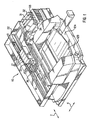
- FIG. 1 is a perspective view of a printer which improves image quality by reducing drop placement, shape, and density errors on a printed medium.
- FIG 2 is a perspective view of a print cartridge including a printhead according to the present invention, which is usable in the printer of FIG. 1 and.
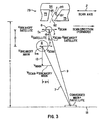
- FIG. 3 is a schematic representation of the ejection of a main drop and satellite drop from a nozzle of the print cartridge of FIG. 2 onto a print medium, illustrating the situation where the tilt of the nozzle and the carriage scanning velocity affect the trajectories of the main and satellite drops so that the drops coincide in the same location on the medium for a given height of the printhead over the medium.
- FIG. 4 is a schematic representation illustrating how the print controller of the printer of FIG. 1 locates and controls drop placement on the medium.
- FIG. 5 is a cross-sectional view of a single ink ejection chamber and nozzle of the printhead in the print cartridge of FIG. 2.
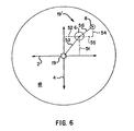
- FIG. 6 is a schematic representation of drop placement and shape errors with respect to the scan axis and medium advance axis.
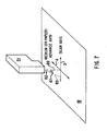
- FIG. 7 is a schematic representation of tilting the bore of a nozzle along the scan axis of FIG. 6 to reduce drop placement error.
- FIG. 8A is a schematic illustration of satellite drops having PAD and SAD error.
- FIG. 8B is a schematic illustration of a nozzle producing satellite drops which exhibit minimal PAD and SAD error in a given scanning direction.
- FIG. 8C is a schematic illustration of a nozzle producing satellite drops which exhibit minimal PAD error but substantial SAD error in a scan direction opposite to the scan direction of FIG. 8B.
- FIGS. 9A-B are schematic illustrations of printed output from circular nozzles having no tilt and exhibiting significant PAD and SAD error.
- FIG. 9C is a schematic illustration of printed output from nozzles having circular bores tilted along the scan axis in a direction opposite to the scanning direction as in FIG. 7, or from asymmetric non-circular bores (with or without such tilt) in which the breakoff velocity vector is along the scan axis in the direction opposite to the scanning direction, the printed output exhibiting reduced PAD and SAD error.
- FIG. 9D is a schematic illustration of printed output from nozzles having circular bores tilted along the scan axis in the same direction as the direction of scanning, or from asymmetric non-circular bores (with or without such tilt) in which the breakoff velocity vector is along the scan axis in the same direction as the scanning direction, the printed output exhibiting reduced PAD error but significant SAD error.
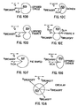
- FIGS. 10A-G are illustrations, viewed at the nozzle member, of the nozzle bore shape and breakoff velocity vectors associated with different nozzle bore geometries usable with the printhead of the print cartridge of FIG. 2.
- FIG. 11 is a flowchart of a method for depositing drops of an ink on a medium with the inkjet printer of FIG 1.
- Referring now to the drawings, there is illustrated a
novel inkjet printer 10 constructed in accordance with the present invention and operated in accordance with a novel printing method which provides accurate drop placement at high scanning speeds so as to minimize visual printing defects such as banding. Theprinter 10 includes anovel printhead 79 having ink ejection nozzle features which reduce drop placement error in the medium advance direction 4 (known as PAD error) and in the scan axis direction 2 (known as SAD error). The minimization of objectionable banding significantly improves the quality of the printed output produced by theprinter 10. - Considering now the
inkjet printer 10 with reference to FIGS. 1 and 2, theprinter 10 generally includes aframe 14 to which acarriage 20 is moveably mounted along a slidingrail 22. Thecarriage 20 has one ormore stalls 23 for holding one or morecorresponding print cartridges 21 and moving them relative to the surface of anadjacent print medium 18 such as paper, transparency film, or textiles. Eachprint cartridge 21 includes aprinthead 79 havingink ejection chambers 94 for controllably ejecting the drops of the ink or other fluid used for printing. Anozzle member 75 is attached to all of theink ejection chambers 94 and defines the wall through which the ink is ejected from thechambers 94 onto the medium 18. To allow the emission of ink from theprinthead 79,nozzles 82 are formed in thenozzle member 75, anindividual nozzle 82 associated with eachcorresponding chamber 94. As will be explained subsequently in greater detail, thenozzles 82 can be constructed with geometric features according to the present invention that reduce drop placement errors on theprint medium 18. - In operation, and with reference to FIG. 3, a
main drop 6 is controllably ejected from selected ones of thenozzles 82 toward the medium 18 with afirst trajectory 7, followed by asatellite drop 8 from selected ones of thenozzles 82 toward the medium 18 in asecond trajectory 9. As will be explained subsequently in greater detail, themain drop 6 and thesatellite drop 8 have reduced drop placement error, including substantially no drop placement error in a medium or paper advance direction 4 (i.e. substantially no PAD error). In addition, any drop placement error in the scanning direction 2 (SAD error) that does occur becomes more consistent from nozzle to nozzle, and for repetitive ink ejections from thesame nozzle 82 in the same scanning direction. - Considering now a preferred embodiment of the
printer 10 in further detail, and as best understood with reference to FIGS. 1 and 4, theprinter 10 includes an input tray 12a in which a supply of the media to be printed are stacked prior to printing, and an output tray 12b where the media are placed after printing is complete. Each medium 18 is fed into the printer and positioned adjacent thecarriage 20 for printing. Theprint medium 18 has a plurality of pixel locations, such aspixel location 19, organized in a rectangular array of rows (along the medium advance axis 4) and columns (along the scan axis 2) on the medium 18. Theprint cartridge 21 is preferably installed in thecarriage 20 such that theprinthead 79 is facing in a downward direction and ejecting ink vertically down onto the surface of the medium 18. Ink can be supplied to theprinthead 79 in a number of different ways, including from a reservoir which is self-contained in theprint cartridge 21, or via atube 36 from an off-carriage ink reservoir or vessel, such as one ofreservoirs printer 10 also contains aprint controller 50 which receives the data to be printed on the medium 18 from a data source such as a computer (not shown) which is connected to theprinter 10, and determines how and when to print corresponding dots on the medium 18. Thecontroller 50 orchestrates the printing by issuing carriage scan control commands to thescan drive mechanism 15 which moves thecarriage 20 relative to the medium 18 in thescan direction 2, by issuing medium advance control commands to themedium drive mechanism 22 which moves the medium 18 relative to thecarriage 20 in themedium advance direction 4, and by issuing ink emission control commands to theappropriate print cartridge 21 to eject drops of fluid from the desirednozzles 82 of the desiredprinthead 79 onto the medium 18. The mechanism of ink ejection will be subsequently described in greater detail. - Considering now in further detail a preferred embodiment of the
print cartridge 21 according to the present invention, a flexible tape ("flex tape") 80 is adhesively mounted to the surface of thecartridge 21. Thenozzle member 75 is preferably integral to theflex tape 80 with thenozzles 82 laser-ablated in the polymeric material, although alternatively thenozzle member 75 can be a metallic nozzle plate separate from theflex tape 80 and havingnozzles 82 formed in the plate by any conventional process, with theflex tape 80 having a cutout in the region where the nozzle plate is located. The composition of thenozzle member 75 is substantially uniform throughout, and has a planar surface that is positioned adjacent the surface of the medium 18 during printing. Where the surface of the medium 18 is positioned in theprinter 10 so as to form a printing plane, the planar surface of thenozzle member 75 is preferably positioned coplanar with the printing plane. The electrical signals for the ink emission control commands are communicated to thecartridge 21 through a set ofinterconnection pads 86 on the front surface of theflex tape 80. When thecartridge 21 is seated in thestall 23, a set of mating contacts (not shown) in thestall 23 and connected to theprint controller 50 transmit the electrical signals from theprint controller 50 to theinterconnection pads 86. On theprint cartridge 21, thepads 86 are electrically connected to theprinthead 79 via traces contained in aflex tape 80 which mate with theprinthead 79 when it is mounted to the back surface of theflex tape 80. In this way the electrical signals necessary to activate the thin-film resistors 70 are transmitted front theprint controller 50 to theink ejection chambers 94. In the case of an off-carriage ink supply, ink is supplied through thetube 36 to anink input port 60 of theprint cartridge 21, and then internally to theink ejection chambers 94, as will be discussed subsequently in further detail. Thenozzles 82 are organized into two parallel columns of equally-spaced nozzles, with a column 85a containing a quantity of odd-numberednozzles 82 and a column 85b containing the same quantity of even-numberednozzles 82. The nozzle columns 85a,b are offset from each other in themedium advance direction 4 by a distance equal to one-half of the spacing between two nozzles in a column, such that the two columns 85a,b can be logically treated by theprint controller 50 as a single column of twice as many nozzles and having twice the number of nozzles per cm (inch) in themedium advance direction 4 of either column 85a,b individually. Analyzed from the perspective of the printedmedium 18, rows of drops printed by odd nozzles alternate with rows of drops printed by even nozzles. As it is scanned along thescan axis 2 with respect to the medium 18, theprinthead 79 produces a printed swath having a height in themedium advance direction 4 corresponding to the number and spacing of the columns 85a,85b ofnozzles 82. The medium 18 is periodically advanced in themedium advance direction 4 by an distance equivalent to part or all of the swath height, depending on the particular printmode used by theprinter 10 to fully print a swath. - Considering now in further detail a single
ink ejection chamber 94 and associatednozzle 82 of a preferred embodiment of theprinthead 79, and with reference to FIG. 5, thechamber 94 has athin film resistor 70 formed on asubstrate 28. A side edge of thesubstrate 28 is shown asedge 86. Abarrier layer 30 is deposited on thesubstrate 28 so as to form thechamber 94. Thenozzle member 75 is attached to thebarrier layer 30 by a thinadhesive layer 84. In operation, ink flows around theside edge 86 of thesubstrate 28, and into theink channel 81 and associatedink ejection chamber 94, as shown by thearrow 88. Upon energization of thethin film resistor 70 by electrical signals as orchestrated by theprint controller 50, a thin layer of the adjacent ink is superheated, causing explosive vaporization and, consequently, causing a main drop and one or more satellite drops of ink to be ejected through thenozzle 82. Theink ejection chamber 94 is then refilled by capillary action. The time required to heat the ink, vaporize and eject main and satellite drops, and refill thechamber 94 defines a maximum firing frequency at which ink can be ejected from thechamber 94 onto the medium 18. In the preferred embodiment, ink is ejected from thechamber 94 at the same firing frequency regardless of in which direction along thescan axis 2 theprint cartridge 21 is being moved; there is no need to print more slowly in one direction than in another. - Considering now with reference to FIGS. 3, 4, and 6 the drop placement error (also known as directionality error or concentricity error) associated with the main and satellite drops ejected from the
ink ejection chamber 94 is defined as the distance between the printeddrop location 19', and the intendedpixel location 19. The drop placement error can have a scan axis directionality ("SAD") component in the direction along thescan axis 2, and a paper axis directionality ("PAD") component in the direction along themedium advance axis 4. Where the main 6 andsatellite 8 drops are not coincident on the medium 18 (as in FIG. 6), the drop placement error may be determined with respect to a centroidal position of the twodrops drops drops main drop 6 having adrop placement error 53 with aPAD component 51 and a SAD component 52 relative to the intendedlocation 19, and thesatellite drop 8 having a drop placement error 56 with aPAD component 54 and a SAD component 55 with respect to themain drop 6. - In
many printheads 79, the drop placement error of themain drop 6 tends to be relatively consistent, and some types of errors can often be compensated for by theprint controller 50 so as to more closely align themain drop 6 to the desiredlocation 19. However, in prior printheads the drop placement error of thesatellite drop 8 tends to have variable amounts of SAD and PAD error, (and thus a variable aggregate direction vector) fromchamber 94 tochamber 94, and from drop to drop from thesame chamber 94. This variable drop placement error cannot be compensated for by theprint controller 50, and becomes'worse at higher scanning speeds. While the directionality of themain drop 6 is less affected by the angling and the shape of thenozzle 82, these nozzle features have a more significant effect on the directionality of thesatellite drop 8. By carefully controlling these characteristics, the present invention reduces the drop placement error of thesatellite drop 8 so as to minimize adverse effects on print quality. - Considering in further detail, with reference to FIGS. 7 and 8A, the effect on the
satellite drop 8 of angling or tilting the typically circular bore of thenozzle 82 with respect to the vertical 89, aprint cartridge 21 installed in theprinter 10 in an orientation such that theaxes 85 of the nozzle bores are substantially vertical tends to have a highly variable directionality error. This effect is at least partially due to the difficulty in ensuring that the bore axes 85 in thenozzles 82 of installedprint cartridges 21 are absolutely vertical; in most cases, theaxes 85 will have a small amount of tilt, with the tilt occurring in different directions due to minor manufacturing variations in the fabrication of the nozzles and the installation of thecartridge 21 in theprinter 10. As illustrated in FIG. 8A, a substantiallyvertical nozzle 82 typically produces satellite drops 8 having both PAD and SAD error which varies from nozzle firing to nozzle firing. However, by fabricating thenozzles 82 with a bore axis tilt in a given direction in excess of the amount of tilt from manufacturing variations, the direction and magnitude of the drop placement error can be more precisely controlled. In this situation, the effects of the intentional tilt will dominate the effects of the manufacturing and installation variations, allowing improved drop placement performance. It is known to provide printheads with such tilted nozzles from, for example, EP-A-1 020 288 and US 5,992,968. The intentional tilt typically has atilt angle Ø 87 in the range of 0.2 to 1.4 degrees, and more preferably in the range of 0.4 to 0.9 degrees. Utilizing such a tilt angle ∅ 87 for the intentional tilt will make the drop placement performance less sensitive to fabrication and installation variations. Since PAD error is typically more perceptible to the human eye than SAD error, the intentional tilt is induced in a direction that will minimize PAD error. PAD error can be minimized by orienting the intentional tilt from vertical 89 in the bore axes 85 to be along thescan axis 2. The same amount and direction of intentional tilt could be induced in both the odd nozzles 85a and the even nozzles 85b, but such an embodiment is outside the scope of the claimed invention. The direction of the intentional tilt (e.g. in the forward scanning direction or the reverse scanning direction) along thescan axis 2 does not significantly affect the PAD error reduction. - Considering now the effect on SAD error that occurs when an intentional tilt in the direction of the
scan axis 2 is introduced in thebore axis 85 to minimize PAD error, and with reference to FIGS. 3 and 8B-C, several factors determine themain drop trajectory 7 and thesatellite drop trajectory 9 which result in the drop placement location of themain drop 6 andsatellite drop 8 on the medium 18. Thesatellite drop 8 has a lower expulsion velocity (Vsatellite, typically about six to eight meters per second) 15 than the expulsion velocity (Vmain, typically about twelve meters per second) 13 of amain drop 6. The difference in expulsion velocities and ejection times, combined with the movingprint cartridge 21, tends to cause thesatellite drop 8 to land away from themain drop 6 in the downstream direction of scanning. In addition, during ejection thesatellite drop 8 also acquires abreakoff velocity V breakoff satellite 5s in the direction of nozzle tilt. This velocity component is present to a lesser degree in themain drop 6, which acquires abreakoff velocity V breakoff main 5m. When theprint cartridge 21 is scanned in the same direction as thebore axis 85 is tilted (e.g. scanning in the reverse scanning direction when the tilt is also in the reverse scanning direction), the scanning velocity (Vscan) 3 adds to thebreakoff velocities 5s,m. The difference in magnitudes of thebreakoff velocities 5s,m, combined with the difference inexpulsion velocities satellite drop 8 to move away from themain drop 6, with the printed result as illustrated in FIG. 8C. Conversely, when scanning in the direction opposite to the tilt (e.g. scanning in the forward scanning direction when the tilt is in the reverse scanning direction, as illustrated in FIG. 3), the scanning velocity (Vscan) 3 subtracts from thebreakoff velocities 5s,m to cause thesatellite drop 8 to move back towards themain drop 6 during flight, as illustrated in FIG. 8B. For given expulsion velocities, the optimal amount of nozzle tilt is determined from the scanning velocity (Vscan) 3, the vertical height (H) of theprinthead 79 above the medium 18, and the time delay between ejection of themain drop 6 and thesatellite drop 8, with the amount of tilt selected so as to have thesatellite drop 8 coincide on the medium 18 with themain drop 6 while theprint cartridge 21 is scanning in the direction opposite to the tilt, as illustrated in FIG. 3. For a scanning velocity of approximately 0.75 meters per second, a vertical height of about 1250 micrometers, and an ejection delay of about 10 microseconds, a nozzle tilt of 0.2 to 1.4 degrees in the scanning direction will consistently cause the placement on the medium 18 of themain drop 6 andsatellite drop 8 to coincide - FIGS. 9A-D illustrate the drop placement error for a set of
nozzles 82. FIGS. 9A-B illustrate magnified ink depositions on the medium 18 printed in the forward and reverse scanning directions from aprior art printhead 79 withcircular nozzles 82 having untilted (i.e. substantially vertical) bores respectively. It is observed that the occurrence and drop placement error of satellite drops differs from nozzle to nozzle, and for different firings of the same nozzle, regardless of the scanning direction, causing objectionable horizontal banding. By comparison, the main 6 andsatellite 8 drops of FIG. 9C, which illustrates output printed in the forward scanning direction from aprinthead 79 havingnozzles 82 tilted in the reverse scanning direction (as known, for example, from EP-A-1 020 822 and US 5,992,968) , consistently coincide in the same location such that thesatellites 8 are not visible. In FIG. 9D, which illustrates output printed in the reverse scanning direction from thesame printhead 79 of FIG. 9C, satellite drops are consistently visible, but since there is no perceivable PAD error, there is no horizontal banding. In order for thenozzles 82 to operate as illustrated in FIGS. 9C-D and heretofore described, it may be required to eject several drops from the nozzles to initialize the proper behavior. These start-up emissions can either be printed on a very small portion of the medium 18 or in an ink spittoon or service station (not shown) in theprinter 10 - In one embodiment, not a part of the claimed invention, the odd column 85a and the even column 85b of
nozzles 82 on theprinthead 79 are both tilted in the same direction. Such a configuration will generate coincident main 6 andsatellite 8 drops from all nozzles in one scanning direction, and separated main 6 andsatellite 8 drops from all nozzles in the other scanning direction. As a result, the entire swath printed by theprinthead 79 in one scanning direction produces output as in FIG. 9C, and output as in FIG. 9D in the other scanning direction. Such a nozzle configuration is particularly beneficial in providing high image quality, particularly for the edges of text, when used in combination with a one-pass unidirectional printmode that deposits drops only when scanning in the direction in which themain drops 6 and the satellite drops 8 coincide. In addition to the main and satellite drops forming substantially round spots on the medium 18, the spot size and spot density (equivalent to perceived lightness or darkness of the spot) are also uniform for all spots, and adjacent drops can coalesce to form uniform areas during drying. - In accordance with the claimed invention, the odd column 85a and the even column 85b of
nozzles 82 on theprinthead 79 are each tilted in opposite directions. Since odd and even nozzles form alternate rows on the medium 18, such a configuration will generate printed output where, for a given scanning direction, the spots in one printed row have coincident main and satellite drops, while the spots in the adjacent printed row have distinct main and satellite drops. Such a nozzle configuration is useful in printmodes utilizing any number of passes, but is particularly beneficial when used in combination with a one-pass bidirectional printmode, where alternate swaths are printed in opposite scanning directions. Since each swath of a one-pass bidirectional printmode contains both coincident and non-coincident main 6 andsatellite 8 drops, this nozzle arrangement where the columns 85a,b are tilted in opposite directions provides a balanced design in which the perceived image quality of alternate swaths is closely matched. - An alternate embodiment of the present invention, as best understood with reference to FIGS. 10A-G, utilizes non-circular nozzle bores through the
nozzle member 75, instead of circular bores. Such a nozzle design provides beneficial drop placement effects similar to those obtainable, as has been heretofore described, by tilting thenozzles 82. While the breakoff velocity (Vbreakoff)vector 5s,m of thesatellite drop 8 can occur in any of a large number of different directions for different firings of a circular bore 82a, the geometric features of asymmetric non-circular bores cause thebreakoff velocity vector 5s,m to consistently occur in a single direction. Asymmetric non-circular bores are symmetrical about thescan axis 2, but not about themedium advance axis 4, and are known from EP-A-0 792 744. Those of the invention include, but are not limited to, bores having the shape of alopsided circle 82b,cashew 82c, lopsided figure-8 (or lopsided kidney) 82d, pie-shape 82f, and lopsided cashew 82g. Symmetric non-circular bores can have a small number of possiblebreakoff velocity vectors 5s,m; for instance, abore 82e having the shape of a figure-8 (or kidney) has two possible vectors located at either side of the waist of the figure-8. To minimize PAD error,non-circular bores 82b-g must be rotated so as to align the (or one of the) breakoff vectors with the scanning axis. In addition, in order to establish a consistent andrepeatable breakoff vector 5s,m so as to ensure that all nozzles have a consistent SAD for all firings in a scan direction, a symmetric non-circular bore must also be tilted along the scanning axis as described heretofore for a circular bore. As a practical matter, since tilt has a stronger effect on directionality than does non-circularity of the nozzle bore, tilting even asymmetric non-circular bores is preferable unless absolute vertical alignment of the bores when thecartridge 21 is installed in theprinter 10 can otherwise be assured. The nozzle bores preferably widen, or taper away, from the surface of thenozzle member 75 at which the drops are ejected and toward the interior of thenozzle member 75. The tapering is preferably constant at a taper angle of about eight to nine degrees, such that the bores retain the same cross-sectional shape throughout thenozzle member 75. - The present invention can also be implemented, with reference to FIG. 11, as a
method 200 for depositing drops of an ink on a medium 18 with aninkjet printer 10. At 202, aprinthead 79 withnozzles 82 whose bore axes are tilted from orthogonal (with respect to the plane of the medium 18) along thescanning axis 2 in the forward or rearward direction is provided. The odd nozzles and the even nozzles can be tilted in the same direction or different directions, forward or rearward. Only the embodiment in which the odd nozzles and the even nozzles are tilted in different (opposite) directions along the scanning axis falls within the scope of the claimed invention. At 204, theprinthead 79 is moved relative to theprint medium 18 along thescanning axis 2 in the forward or rearward direction. Typically thisprinthead 79 movement begins at one side of theprinter 10, or at a location corresponding to the position on the medium 18 to be printed nearest that side of theprinter 10, and proceeds along thescanning axis 2 to the other side of theprinter 10 or to a position corresponding to the farthest position on the medium 18 to be printed in the current swath. At 206, theprinthead 79, while moving, controllably ejectsmain drops 6 from selectednozzles 82 onto the medium 18 with afirst trajectory 7, as described heretofore. At 208, and also as described heretofore, theprinthead 79 also responsively ejects one or more satellite drops 8 from the selectednozzles 82 with asecond trajectory 9 which has substantially the same displacement in themedium advance direction 4 as thefirst trajectory 7, so as to minimize PAD error. In addition, if the tilt of thenozzles 82 is in a direction along thescan axis 2 opposite to the current direction (forward or rearward) of movement, then (depending on thebreakoff velocities 5s,m and other factors, and as previously described) themain drop 6 and thesatellite drop 8 may coincide on the medium 18. At 210, when the current traversal of theprinthead 79 along thescan axis 2 is complete, theprint medium 18 may be advanced relative to theprinthead 79 in themedium advance direction 4. However, in some multi-pass printmodes, this advance may not occur after each traversal. At 212, and if printing is complete, the method ends. If printing is not complete, the next action to be taken depends on whether the printmode is unidirectional or bidirectional as performed at 214. If bidirectional, the direction of printhead motion is reversed at 216, and the method continues at 204 with traversal occurring in the opposite direction as on the previous pass. In the preferred embodiment, the scanning speed is the same in both directions so as to maximize throughout If unidirectional, the printhead is moved in the opposite direction without printing at 218, and the method continues at 204 with traversal occurring in the same direction as for the previous pass. - From the foregoing it will be appreciated that the novel printhead having printhead nozzles with two columns of tilted or (optionally non-circular) bores , those of one column being tilted along a scanning axis in a first direction while those of the other column are tilted along the scanning axis in an opposite direction, and method for reducing drop placement errors as provided by the present invention represent a significant advance in the art. Although several specific embodiments of the invention have been described and illustrated, the invention is not limited to the specific methods, forms, or arrangements of parts so described and illustrated. The claimed invention shall not be considered "ejector-specific" and is not limited to any particular applications, uses, and fluid compositions. It is important to note that the present invention is especially suitable for use with fluid delivery systems that employ thermal inkjet technology. Accordingly, the novel orifice plate structures discussed herein have been described in connection with thermal inkjet technology with the understanding that the invention shall not be limited to this type of system. The claimed technology is instead prospectively applicable to a wide variety of different printing devices provided that they again employ the basic structures recited herein which include a substrate, at least one ejection chamber on the substrate, and an orifice plate positioned above the substrate/ ejection chamber(s) having nozzle(s) therein. In addition, while ink is the preferred embodiment of a fluid to be printed on the medium, the present invention is not limited to the ejection and depositing of ink. Other fluids capable of vaporization upon the application of temperature can be used with the novel features disclosed herein. The invention is limited only by the claims.
Claims (10)
- A printhead (79) for ejecting drops (6,8) of a fluid onto a medium (18) during movement along a scanning axis (2), comprising:a plurality of chambers (94) for controllably ejecting the drops (6,8);a nozzle member (75) attached to the printhead (79) and defining a wall of each of the chambers, the nozzle member having a planar surface positionable adjacent the medium (18); anda plurality of nozzles (82) formed in the nozzle member (75) and in fluidic communication with each chamber (94), wherein certain ones of the nozzles (82) have a nozzle axis (85) tilted along the scanning axis (2), characterised in thatthe nozzles (82) are organized in two parallel columns (85a, 85b) of equally-spaced nozzles, the nozzle columns (85a, 85b) being offset from each other in a media advance direction (4), orthogonal to the scanning axis (2), by a distance equal to one-half of the spacing between two nozzles in a column; andwherein the nozzles of one of the columns (85a) are tilted in an opposite direction to the nozzles of the other of the columns (85b).
- The printhead (79) of claim 1, wherein the certain ones of the nozzles (82) have a non-circular bore (82b-g) through the nozzle member (75).
- The printhead (79) of claim 1 or claim 2. wherein the nozzle axis (85) is tilted between 0.2 degrees and 1.4 degrees from vertical, preferably between 0.4 degrees and 0.9 degrees from vertical.
- The printhead (79) of claim 2, wherein the bore (82e) has a cross-sectional shape throughout the nozzle member (75) as illustrated in Figure 10E.
- The printhead (79) of claim 2, wherein the non-circular bore (82b-g) is symmetrical about the scanning axis (2) but asymmetrical about the medium advance axis (4).
- The printhead (79) of claim 5, wherein the bore (82b, 82c, 82d, 82f, 82g) has a cross-sectional shape throughout the nozzle member (75) as illustrated in Figure 10E as respectively illustrated in Figures 10B-10D. 10F and 10G.
- A method of printing (200), comprising the steps of:a) providing (202) a printhead (79) in accordance with any preceding claim;b) moving (204) the printhead relative to the print medium (18) along the scanning axis (2) in a forward or rearward direction;c) while moving, controllably ejecting (206) main drops (6) from selected nozzles (82) onto the medium (18) with a first trajectory (7);d) responsively ejecting (208) satellite drops (8) from the selected nozzles onto the medium (18) with a second trajectory (9) which has the same displacement in the medium advance direction (4) as the first trajectory (7);e) advancing (210) the print medium (18) relative to the printhead (79) in the medium advance direction (4);f) determining (212) whether printing has been completed;g) if printing has not been completed, repeating steps b) to f).
- The method of claim 7, further comprising, between steps f) and g), the step of:fA) reversing (216) the direction of printhead motion, printing thus being conducted in a bidirectional printmode.
- The method of claim7 or claim 8, wherein the nozzle axis (85) is tilted at an angle of tilt (87), the method further comprising the step of determining an optimal amount of nozzle tilt (87) for given drop velocities from the scanning velocity (3) of the printhead (79), the vertical height (H) of the printhead (79) above the medium (18), and the time delay between ejection of the main drop (6) and the satellite drop (8), the amount of tilt selected so as to deposit the main drop (6) and the satellite drop (8) from an individual one of the plurality of nozzles (82) in one of the nozzle columns (85a) in substantially the same location (19) on the medium (18) while the printhead is moving in the forward direction and to deposit the main drop (6) and the satellite drop (8) from an individual one of the plurality of nozzles (82) in the other of the nozzle columns (85b) in another substantially the same location (19) on the medium (18) while the printhead is moving in the rearward direction.
- The method of claim 7, 8 or 9, wherein printing is conducted using a one-pass printmode.
Applications Claiming Priority (2)
| Application Number | Priority Date | Filing Date | Title |
|---|---|---|---|
| US09/686,037 US6860588B1 (en) | 2000-10-11 | 2000-10-11 | Inkjet nozzle structure to reduce drop placement error |
| US686037 | 2000-10-11 |
Publications (2)
| Publication Number | Publication Date |
|---|---|
| EP1197335A1 EP1197335A1 (en) | 2002-04-17 |
| EP1197335B1 true EP1197335B1 (en) | 2006-06-07 |
Family
ID=24754641
Family Applications (1)
| Application Number | Title | Priority Date | Filing Date |
|---|---|---|---|
| EP01308584A Expired - Lifetime EP1197335B1 (en) | 2000-10-11 | 2001-10-08 | Inkjet nozzle structure to reduce drop placement error |
Country Status (4)
| Country | Link |
|---|---|
| US (1) | US6860588B1 (en) |
| EP (1) | EP1197335B1 (en) |
| JP (1) | JP2002160368A (en) |
| DE (1) | DE60120317T2 (en) |
Families Citing this family (16)
| Publication number | Priority date | Publication date | Assignee | Title |
|---|---|---|---|---|
| US7004555B2 (en) * | 2002-09-10 | 2006-02-28 | Brother Kogyo Kabushiki Kaisha | Apparatus for ejecting very small droplets |
| US7059698B1 (en) * | 2002-10-04 | 2006-06-13 | Lexmark International, Inc. | Method of altering an effective print resolution of an ink jet printer |
| EP1694507A4 (en) | 2003-07-31 | 2010-01-06 | Nissim Einat | Ink jet printing method and apparatus |
| WO2005042257A1 (en) * | 2003-11-04 | 2005-05-12 | Koninklijke Philips Electronics N.V. | Increased droplet placement accuracy in inkjet printing |
| JP2005254579A (en) * | 2004-03-10 | 2005-09-22 | Brother Ind Ltd | Droplet jet apparatus |
| KR20060123842A (en) * | 2005-05-30 | 2006-12-05 | 삼성전자주식회사 | Ink injection apparatus, image forming apparatus having the same and method for forming image |
| JP2007283720A (en) * | 2006-04-19 | 2007-11-01 | Canon Finetech Inc | Recording head and ink-jet recording device |
| JP5116545B2 (en) * | 2007-05-25 | 2013-01-09 | キヤノン株式会社 | Liquid ejection method |
| US8354062B2 (en) * | 2007-06-15 | 2013-01-15 | Xerox Corporation | Mixing device and mixing method |
| US8328330B2 (en) * | 2008-06-03 | 2012-12-11 | Lexmark International, Inc. | Nozzle plate for improved post-bonding symmetry |
| US10717278B2 (en) | 2010-03-31 | 2020-07-21 | Hewlett-Packard Development Company, L.P. | Noncircular inkjet nozzle |
| KR101657337B1 (en) | 2010-03-31 | 2016-09-19 | 휴렛-팩커드 디벨롭먼트 컴퍼니, 엘.피. | Noncircular inkjet nozzle |
| US8919928B2 (en) | 2011-01-31 | 2014-12-30 | Hewlett-Packard Development Company, L.P. | Fluid ejection device having firing chamber with mesa |
| JP5901149B2 (en) * | 2011-06-01 | 2016-04-06 | キヤノン株式会社 | Liquid discharge head and manufacturing method thereof |
| WO2016029925A1 (en) | 2014-08-25 | 2016-03-03 | Hewlett-Packard Development Company, L.P. | Determining an alignment characteristic |
| GB202109076D0 (en) * | 2021-06-24 | 2021-08-11 | Xaar Technology Ltd | A nozzle plate for a droplet ejection head, a droplet ejection apparatus and a method for operating the same |
Family Cites Families (21)
| Publication number | Priority date | Publication date | Assignee | Title |
|---|---|---|---|---|
| DE2358168C2 (en) | 1972-11-24 | 1982-06-03 | Research and Development Laboratories of Ohno Co.Ltd., Yokohama, Kanagawa | Registration unit |
| US3886565A (en) | 1974-05-09 | 1975-05-27 | Tokyo Shibaura Electric Co | Injection nozzle for an ink jet printer |
| US3928855A (en) | 1974-12-18 | 1975-12-23 | Ibm | Method and apparatus for controlling satellites in an ink jet printing system |
| US4014029A (en) | 1975-12-31 | 1977-03-22 | International Business Machines Corporation | Staggered nozzle array |
| US4330787A (en) | 1978-10-31 | 1982-05-18 | Canon Kabushiki Kaisha | Liquid jet recording device |
| US4278983A (en) | 1979-05-23 | 1981-07-14 | Gould Inc. | Ink jet writing device |
| GB2061829B (en) | 1979-10-29 | 1983-11-09 | Suwa Seikosha Kk | Ink jet head |
| JP3032021B2 (en) | 1990-02-02 | 2000-04-10 | キヤノン株式会社 | Ink jet recording device |
| JP2559515B2 (en) | 1990-02-23 | 1996-12-04 | 株式会社日立製作所 | Fuel injection valve device and manufacturing method thereof |
| JPH06171084A (en) * | 1992-02-07 | 1994-06-21 | Seiko Epson Corp | Ink jet recording head |
| JPH0623985A (en) | 1992-07-06 | 1994-02-01 | Seiko Epson Corp | Ink jet head and its manufacture |
| US5461406A (en) | 1994-01-03 | 1995-10-24 | Xerox Corporation | Method and apparatus for elimination of misdirected satellite drops in thermal ink jet printhead |
| US5992968A (en) | 1994-06-15 | 1999-11-30 | Canon Kabushiki Kaisha | Ink jet printing method and apparatus |
| JP3126276B2 (en) | 1994-08-05 | 2001-01-22 | キヤノン株式会社 | Inkjet recording head |
| US5811019A (en) | 1995-03-31 | 1998-09-22 | Sony Corporation | Method for forming a hole and method for forming nozzle in orifice plate of printing head |
| US5731827A (en) * | 1995-10-06 | 1998-03-24 | Xerox Corporation | Liquid ink printer having apparent 1XN addressability |
| US6527369B1 (en) | 1995-10-25 | 2003-03-04 | Hewlett-Packard Company | Asymmetric printhead orifice |
| US6371596B1 (en) * | 1995-10-25 | 2002-04-16 | Hewlett-Packard Company | Asymmetric ink emitting orifices for improved inkjet drop formation |
| US5889538A (en) | 1995-11-24 | 1999-03-30 | Oki Data Corporation | Ink jet recording apparatus |
| US6139134A (en) | 1996-10-14 | 2000-10-31 | Sony Corporation | Printer |
| US6299270B1 (en) | 1999-01-12 | 2001-10-09 | Hewlett-Packard Company | Ink jet printing apparatus and method for controlling drop shape |
-
2000
- 2000-10-11 US US09/686,037 patent/US6860588B1/en not_active Expired - Lifetime
-
2001
- 2001-10-08 DE DE60120317T patent/DE60120317T2/en not_active Expired - Lifetime
- 2001-10-08 EP EP01308584A patent/EP1197335B1/en not_active Expired - Lifetime
- 2001-10-10 JP JP2001313253A patent/JP2002160368A/en active Pending
Also Published As
| Publication number | Publication date |
|---|---|
| JP2002160368A (en) | 2002-06-04 |
| DE60120317T2 (en) | 2007-02-15 |
| DE60120317D1 (en) | 2006-07-20 |
| EP1197335A1 (en) | 2002-04-17 |
| US6860588B1 (en) | 2005-03-01 |
Similar Documents
| Publication | Publication Date | Title |
|---|---|---|
| EP1197335B1 (en) | Inkjet nozzle structure to reduce drop placement error | |
| US6193347B1 (en) | Hybrid multi-drop/multi-pass printing system | |
| EP1827847B1 (en) | Fluid ejection device nozzle array configuration | |
| EP0913257B1 (en) | Apparatus for generating high frequency ink ejection and ink chamber refill | |
| EP0914950A2 (en) | An ink jet printhead assembled from partial width array printheads | |
| EP0539157B1 (en) | Colour ink jet recording apparatus | |
| JP4926680B2 (en) | Inkjet recording device | |
| CN101291812A (en) | Ink jet recording head, ink jet cartridge with ink jet recording head, and ink jet recording apparatus | |
| JPH06135007A (en) | Ink jet recorder | |
| US6402280B2 (en) | Printhead with close-packed configuration of alternating sized drop ejectors and method of firing such drop ejectors | |
| KR100940128B1 (en) | Ink jet recording method | |
| EP0913256A2 (en) | Multi-drop merge on media printing system | |
| EP0913259B1 (en) | Apparatus for generating small volume, high velocity ink droplets in an inkjet printer | |
| US6547352B1 (en) | Ink jet recording device | |
| US6648451B2 (en) | Ink jet recording apparatus and ink jet recording head | |
| EP1022148B1 (en) | Printer having media advance coordinated with primitive size | |
| KR101034322B1 (en) | Liquid ejecting method and liquid ejecting apparatus | |
| JP2002192727A (en) | Ink jet recording head, ink jet recorder and ink jet recording method | |
| EP1048471A2 (en) | Method and apparatus for minimizing color hue shifts in bi-directional inkjet printing | |
| US8342647B2 (en) | Inkjet printing apparatus | |
| CN111993791B (en) | Ink jet device and system with enclosed dual feed drop ejector | |
| US20040113975A1 (en) | Color printing with reduced hue shift | |
| EP0897804A2 (en) | Liquid ink printhead | |
| US20060061610A1 (en) | Image forming apparatus | |
| JP2003103767A (en) | Printing system comprising plurality of liquid droplet weights |
Legal Events
| Date | Code | Title | Description |
|---|---|---|---|
| PUAI | Public reference made under article 153(3) epc to a published international application that has entered the european phase |
Free format text: ORIGINAL CODE: 0009012 |
|
| AK | Designated contracting states |
Kind code of ref document: A1 Designated state(s): DE FR GB Kind code of ref document: A1 Designated state(s): AT BE CH CY DE DK ES FI FR GB GR IE IT LI LU MC NL PT SE TR |
|
| AX | Request for extension of the european patent |
Free format text: AL;LT;LV;MK;RO;SI |
|
| 17P | Request for examination filed |
Effective date: 20020619 |
|
| AKX | Designation fees paid |
Free format text: DE FR GB |
|
| 17Q | First examination report despatched |
Effective date: 20041118 |
|
| GRAP | Despatch of communication of intention to grant a patent |
Free format text: ORIGINAL CODE: EPIDOSNIGR1 |
|
| GRAS | Grant fee paid |
Free format text: ORIGINAL CODE: EPIDOSNIGR3 |
|
| GRAA | (expected) grant |
Free format text: ORIGINAL CODE: 0009210 |
|
| AK | Designated contracting states |
Kind code of ref document: B1 Designated state(s): DE FR GB |
|
| REG | Reference to a national code |
Ref country code: GB Ref legal event code: FG4D |
|
| REF | Corresponds to: |
Ref document number: 60120317 Country of ref document: DE Date of ref document: 20060720 Kind code of ref document: P |
|
| ET | Fr: translation filed | ||
| PLBE | No opposition filed within time limit |
Free format text: ORIGINAL CODE: 0009261 |
|
| STAA | Information on the status of an ep patent application or granted ep patent |
Free format text: STATUS: NO OPPOSITION FILED WITHIN TIME LIMIT |
|
| 26N | No opposition filed |
Effective date: 20070308 |
|
| REG | Reference to a national code |
Ref country code: GB Ref legal event code: 732E Free format text: REGISTERED BETWEEN 20120329 AND 20120404 |
|
| REG | Reference to a national code |
Ref country code: FR Ref legal event code: PLFP Year of fee payment: 15 |
|
| PGFP | Annual fee paid to national office [announced via postgrant information from national office to epo] |
Ref country code: GB Payment date: 20150924 Year of fee payment: 15 |
|
| PGFP | Annual fee paid to national office [announced via postgrant information from national office to epo] |
Ref country code: FR Payment date: 20150925 Year of fee payment: 15 |
|
| PGFP | Annual fee paid to national office [announced via postgrant information from national office to epo] |
Ref country code: DE Payment date: 20150922 Year of fee payment: 15 |
|
| REG | Reference to a national code |
Ref country code: DE Ref legal event code: R119 Ref document number: 60120317 Country of ref document: DE |
|
| GBPC | Gb: european patent ceased through non-payment of renewal fee |
Effective date: 20161008 |
|
| REG | Reference to a national code |
Ref country code: FR Ref legal event code: ST Effective date: 20170630 |
|
| PG25 | Lapsed in a contracting state [announced via postgrant information from national office to epo] |
Ref country code: GB Free format text: LAPSE BECAUSE OF NON-PAYMENT OF DUE FEES Effective date: 20161008 Ref country code: FR Free format text: LAPSE BECAUSE OF NON-PAYMENT OF DUE FEES Effective date: 20161102 Ref country code: DE Free format text: LAPSE BECAUSE OF NON-PAYMENT OF DUE FEES Effective date: 20170503 |