EP1193511A1 - Retroreflecting sheet having printed layer - Google Patents
Retroreflecting sheet having printed layer Download PDFInfo
- Publication number
- EP1193511A1 EP1193511A1 EP01919810A EP01919810A EP1193511A1 EP 1193511 A1 EP1193511 A1 EP 1193511A1 EP 01919810 A EP01919810 A EP 01919810A EP 01919810 A EP01919810 A EP 01919810A EP 1193511 A1 EP1193511 A1 EP 1193511A1
- Authority
- EP
- European Patent Office
- Prior art keywords
- layer
- elements
- triangular
- pair
- lateral faces
- Prior art date
- Legal status (The legal status is an assumption and is not a legal conclusion. Google has not performed a legal analysis and makes no representation as to the accuracy of the status listed.)
- Granted
Links
Images


Classifications
-
- G—PHYSICS
- G02—OPTICS
- G02B—OPTICAL ELEMENTS, SYSTEMS OR APPARATUS
- G02B5/00—Optical elements other than lenses
- G02B5/12—Reflex reflectors
- G02B5/122—Reflex reflectors cube corner, trihedral or triple reflector type
- G02B5/124—Reflex reflectors cube corner, trihedral or triple reflector type plural reflecting elements forming part of a unitary plate or sheet
-
- B—PERFORMING OPERATIONS; TRANSPORTING
- B41—PRINTING; LINING MACHINES; TYPEWRITERS; STAMPS
- B41M—PRINTING, DUPLICATING, MARKING, OR COPYING PROCESSES; COLOUR PRINTING
- B41M3/00—Printing processes to produce particular kinds of printed work, e.g. patterns
- B41M3/008—Sequential or multiple printing, e.g. on previously printed background; Mirror printing; Recto-verso printing; using a combination of different printing techniques; Printing of patterns visible in reflection and by transparency; by superposing printed artifacts
-
- B—PERFORMING OPERATIONS; TRANSPORTING
- B42—BOOKBINDING; ALBUMS; FILES; SPECIAL PRINTED MATTER
- B42D—BOOKS; BOOK COVERS; LOOSE LEAVES; PRINTED MATTER CHARACTERISED BY IDENTIFICATION OR SECURITY FEATURES; PRINTED MATTER OF SPECIAL FORMAT OR STYLE NOT OTHERWISE PROVIDED FOR; DEVICES FOR USE THEREWITH AND NOT OTHERWISE PROVIDED FOR; MOVABLE-STRIP WRITING OR READING APPARATUS
- B42D15/00—Printed matter of special format or style not otherwise provided for
-
- B—PERFORMING OPERATIONS; TRANSPORTING
- B44—DECORATIVE ARTS
- B44F—SPECIAL DESIGNS OR PICTURES
- B44F1/00—Designs or pictures characterised by special or unusual light effects
-
- B—PERFORMING OPERATIONS; TRANSPORTING
- B44—DECORATIVE ARTS
- B44F—SPECIAL DESIGNS OR PICTURES
- B44F1/00—Designs or pictures characterised by special or unusual light effects
- B44F1/02—Designs or pictures characterised by special or unusual light effects produced by reflected light, e.g. matt surfaces, lustrous surfaces
- B44F1/04—Designs or pictures characterised by special or unusual light effects produced by reflected light, e.g. matt surfaces, lustrous surfaces after passage through surface layers, e.g. pictures with mirrors on the back
-
- B—PERFORMING OPERATIONS; TRANSPORTING
- B60—VEHICLES IN GENERAL
- B60R—VEHICLES, VEHICLE FITTINGS, OR VEHICLE PARTS, NOT OTHERWISE PROVIDED FOR
- B60R13/00—Elements for body-finishing, identifying, or decorating; Arrangements or adaptations for advertising purposes
- B60R13/10—Registration, licensing, or like devices
-
- E—FIXED CONSTRUCTIONS
- E01—CONSTRUCTION OF ROADS, RAILWAYS, OR BRIDGES
- E01F—ADDITIONAL WORK, SUCH AS EQUIPPING ROADS OR THE CONSTRUCTION OF PLATFORMS, HELICOPTER LANDING STAGES, SIGNS, SNOW FENCES, OR THE LIKE
- E01F9/00—Arrangement of road signs or traffic signals; Arrangements for enforcing caution
- E01F9/50—Road surface markings; Kerbs or road edgings, specially adapted for alerting road users
- E01F9/506—Road surface markings; Kerbs or road edgings, specially adapted for alerting road users characterised by the road surface marking material, e.g. comprising additives for improving friction or reflectivity; Methods of forming, installing or applying markings in, on or to road surfaces
- E01F9/524—Reflecting elements specially adapted for incorporation in or application to road surface markings
-
- B42D2033/18—
-
- B42D2035/14—
-
- B—PERFORMING OPERATIONS; TRANSPORTING
- B42—BOOKBINDING; ALBUMS; FILES; SPECIAL PRINTED MATTER
- B42D—BOOKS; BOOK COVERS; LOOSE LEAVES; PRINTED MATTER CHARACTERISED BY IDENTIFICATION OR SECURITY FEATURES; PRINTED MATTER OF SPECIAL FORMAT OR STYLE NOT OTHERWISE PROVIDED FOR; DEVICES FOR USE THEREWITH AND NOT OTHERWISE PROVIDED FOR; MOVABLE-STRIP WRITING OR READING APPARATUS
- B42D25/00—Information-bearing cards or sheet-like structures characterised by identification or security features; Manufacture thereof
- B42D25/30—Identification or security features, e.g. for preventing forgery
- B42D25/324—Reliefs
Definitions
- the present invention relates to retroreflective sheeting having a printed layer, particularly a triangular cube-comer retroreflective sheeting constituted of triangular cube-corner retroreflective elements (hereinafter also referred to simply as triangular reflective elements) which is characterized by having a printed layer for tone improvement in a part thereof and is useful for signs such as road signs and construction signs; license plates of vehicles such as automobiles and motorcycles; safety equipment such as garments and lifesaving equipment; markings of signboards; and reflectors such as visible light, laser light or infrared light reflective sensors; and the like.
- triangular cube-comer retroreflective sheeting constituted of triangular cube-corner retroreflective elements (hereinafter also referred to simply as triangular reflective elements) which is characterized by having a printed layer for tone improvement in a part thereof and is useful for signs such as road signs and construction signs; license plates of vehicles such as automobiles and motorcycles; safety equipment such as garments and lifesaving equipment;
- Retroreflective sheeting which reflects incident light toward the light source has been well known.
- the sheeting having such retroreflective properties has been used widely in the above-described fields.
- cube-comer retroreflective sheeting making use of the retroreflection theory of cube-corner retroreflective elements such as triangular reflective elements and triangular cube-comer retroreflective sheeting having a vapor-deposition layer on the lateral faces of the triangular reflective elements thereof (hereinafter referred to as vapor-deposited triangular cube-corner retroreflective sheeting) are extremely superior in retroreflectivity to conventional retroreflective sheetings using micro glass beads and have been extending their use year by year because of their excellent retroreflective performance.
- retroreflective sheetings and processes for producing them are described, e.g., in U.S. Patent 3,417,959 and WO98/18028 as to triangular cube-corner retroreflective sheeting, and JP-A-49-106839 (U.S. Patent 3,712,706) as to vapor-deposited triangular cube-corner retroreflective sheeting.
- Vapor-deposited triangular cube-corner retroreflective sheeting has a disadvantage attributed to its retroreflective elements that the appearance is darkened by the influence of the metal color.
- a printed layer has slightly poor adhesion to both the reflective element layer and a surface protective layer and also has poor weatherability, it is liable to suffer lifting in a weathering test. It also has a disadvantage of easily absorbing water.
- a continuous printed layer is provided in a triangular cube-corner retroreflective sheeting or a vapor-deposited triangular cube-corner retroreflective sheeting, the sheeting has poor adhesion around the printed layer and poor weather resistance or water resistance.
- retroreflective sheetings include those using micro glass beads, such as encapsulated retroreflective sheeting and encapsulated lens retroreflective sheeting.
- the encapsulated retroreflective sheeting comprises a light-transmitting support layer, a microbead layer provided opposite to the light incident side of the light-transmitting support layer in which a large number of micro glass beads are arrayed substantially in a monolayer with their almost semi-spherical portions being embedded, a light-transmitting focusing layer which is formed along the surface of the other non-embedded semi-spherical portions of the micro glass beads and has such a thickness that the micro glass beads may substantially focus on the surface of the focusing layer that is not in contact with the micro glass beads, and a light-reflective metal film which is formed on the surface of the focusing layer that is not in contact with the micro glass beads.
- the sheeting can have a light-transmitting surface protective layer superposed on the surface of the light-incident side of the support layer.
- the encapsulated lens retroreflective sheeting comprises a light-transmitting coating layer, a support layer, a lens retroreflective element layer provided on the surface of the support layer which faces the light-transmitting coating layer in which a large number of micro glass beads are arrayed substantially in a monolayer with their almost semi-spherical portions being embedded and with the embedded semi-spherical portions being coated with a light-reflective metal film, and an air layer provided between the light-transmitting coating layer and the lens retroreflective elements.
- the air layer is formed by partly connecting the light-transmitting coating layer and the support layer via joints such that gaps are formed between these layers, and the air layer is partitioned by the joints into a large number of closed small vacant spaces.
- the encapsulated retroreflective sheeting and the encapsulated lens retroreflective sheeting essentially have lower retroreflective performance than the. triangular cube-corner retroreflective sheeting or the vapor-deposited triangular cube-corner retroreflective sheeting. Therefore, where a printed layer is provided, they are incapable of satisfying the requirement for retroreflective performance.
- the present invention provides retroreflective sheeting with an improved hue by a very simple and inexpensive method.
- the inventors of the present invention have conducted extensive investigation on hues of triangular cube-corner retroreflective sheeting or vapor-deposited triangular retroreflective sheeting. As a result, they have found that disposing a specific printed layer on the reflective element layer or the surface protective layer of the retroreflective sheeting provides retroreflective sheeting with excellent weather resistance and water resistance and an improved hue and thus have completed the present invention.
- the present invention provides retroreflective sheeting having a printed layer which comprises at least a reflective element layer made up of a large number of reflective elements and a holding body layer and a surface protective layer provided on the reflective element layer, which is characterized in that the printed layer is provided on the lateral faces of the reflective elements or between the holding body layer and the surface protective layer or on the surface protective layer, the printed layer is formed of a discrete repetitive pattern of unit patterns, and the unit patterns each have an area of 0.15 mm 2 to 30 mm 2 .
- the retroreflective sheeting of the present invention is preferably a triangular cube-corner retroreflective sheeting or vapor-deposited triangular cube-corner retroreflective sheeting each having at least a reflective element layer made up of a large number of reflective elements and a holding body layer and a surface protective layer provided on the reflective element layer. Retroreflective sheetings of these kinds exhibit particularly excellent retroreflective performance so that sufficient retroreflectivity can be obtained even in the presence of a printed layer.
- the reflective element layer made up of a large number of reflective elements and a holding body layer can be of the type known as a reflective element layer of triangular cube-corner retroreflective sheeting or vapor-deposited triangular cube-corner retroreflective sheeting.
- Fig. 1 is a cross-section of an example of the triangular cube-corner retroreflective sheeting according to the present invention, in which a printed layer is provided between a holding body layer and a surface protective layer.
- numeral (1) indicates a surface protective layer; (2) a printed layer for coloring for hue adjustment; (5) a reflective element layer having triangular reflective elements (4) arrayed in a closest-packed configuration; and (3) a holding body layer which holds the reflective elements (4).
- Arrow (11) shows the direction of incident light.
- the reflective elements (4) and the holding body layer (3) which constitute the reflective element layer (5) are generally formed by integral molding but may be molded separately and joined together.
- the retroreflective sheeting of the present invention can further comprise a binder layer (7) making a sealed structure for preventing water from penetrating to the back of the reflective element layer (5), a support layer (8) supporting the binder layer (7), an adhesive layer (9) for sticking the retroreflective sheeting to an adherend structure, and a releasable sheet (10).
- the triangular cube-corner retroreflective sheeting usually has an air layer (6) on the back of the triangular cube-comer retroreflective elements to increase the critical angle for total internal reflection of the reflective element layer (5).
- the reflective element layer (5) and the support layer (8) be sealed by the binder layer (7).
- the sealing can be carried out by the methods described in U.S. Patents 3,190,178 and 4,025,159, JP-A-U-50-28669, etc.
- the printed layer (2) is provided on the lateral faces of the reflective elements (4) or between the holding body layer (3) and the surface protective layer (1) or on the surface protective layer (1). Where the surface protective layer (1) is composed of two or more layers, the printed layer (2) can be provided between the protective layers.
- the printed layer (2) can be usually provided by the methods of gravure printing, screen printing, ink jet printing and the like.
- Printed areas of the printed layer (2) should be discrete. For example, it is formed of a repetitive pattern of discrete unit patterns as shown in Figs. 4 or 5.
- the unit patterns are not limited to those illustrated in Figs. 4 and 5 and include figures, such as ellipses, squares and rectangles, geometric patterns composed of straight lines or curved lines, letters, symbols, and combinations of two or more of these units.
- the unit pattern has an area of 0.15 mm 2 to 30 mm 2 , preferably 0.2 mm 2 to 25 mm 2 , still preferably 0.4 mm 2 to 15 mm 2 .
- a unit pattern area of 0.15 mm 2 or more secures excellent pattern formability and facilitates hue control.
- a unit pattern area of 30 mm 2 or less does not cause a reduction in adhesion strength between two layers around the areas having the printed layer (2) therebetween.
- unit patterns can be arranged at any intervals as long as each unit pattern forms an independent area, they are preferably arranged so that non-printed areas among them may have a minimum width of 0.2 mm to 200 mm, particularly 0.5 mm to 50 mm.
- the printed layer (2) preferably has a total printed area of 2% to 70%, particularly 5% to 40%, based on the area of the surface layer of the retroreflective sheeting.
- the thickness of the printed layer (2) is preferably, but is not limited to, 0.5 to 10 ⁇ m, still preferably 1 to 5 ⁇ m, particularly preferably 2 to 4 ⁇ m. With a thickness of 0.5 ⁇ m or greater, excellent formability of the printed layer (2) is secured, and hue control is easy. With a thickness of 10 ⁇ m or smaller, the printed layer (2) does not cause a reduction in adhesion strength between two layers around the areas having the printed layer (2) therebetween.
- Ink for forming the printed layer (2) comprises a resin component and a colorant and, if desired, various additives, such as a plasticizer, an antifoaming agent, a leveling agent, an ultraviolet absorber, a light stabilizer, a heat stabilizer, and a crosslinking agent. It can further contain a solvent for viscosity adjustment or a like purpose.
- the resin component which can be used in the ink preferably includes, but is not limited to, melamine resins, epoxy resins, urethane resins, vinyl resins, polyester resins and alkyd resins, which are excellent in dispersing properties for colorants, dispersion stability, dissolving properties for solvents, weather resistance, printability, adhesion to films, and the like. They can be used either individually or in the form of a copolymer of two or more thereof.
- the surface protective layer (1) is made of a vinyl chloride resin or a (meth)acrylic resin
- preferred among the above-recited resin components for the ink are an acrylic resin, a vinyl resin or a copolymer thereof.
- the colorant used in the ink is preferably such that the hue is brightened and that hiding properties are obtained.
- Light colors matching the sheeting's hue are preferred.
- white organic pigments, white or yellow inorganic pigments, fluorescent dyes or fluorescent whitening agents are useful.
- White or yellow inorganic pigments are particularly preferred for their excellent hiding properties.
- the organic pigments include Fast Yellow, Disazo Yellow, Permanent Yellow, Lionol Yellow, Chromophthal Yellow, and Irgazin Yellow. They can be used either individually or as a combination thereof.
- the inorganic pigments include white ones, such as titanium oxide, calcium carbonate, barium sulfate, zinc oxide, and zinc sulfide; and yellow ones, such as titanium yellow, and yellow iron oxide. They can be used either individually or as a combination thereof or in combination with the above-described organic pigments.
- Materials for forming the reflective elements (4) and the holding body layer (3) are not particularly limited as far as flexibility, one of the objects of the present invention, is secured. Materials having optical transparency and uniformity are preferred.
- Materials which can be used to form the reflective elements (4) include polycarbonate resins, vinyl chloride resins, (meth)acrylic resins, epoxy resins, styrene resins, polyester resins, fluorine resins, olefin resins such as polyethylene resins and polypropylene resins, cellulosic resins, and urethane resins.
- Ultraviolet absorbers, light stabilizers, antioxidants, etc. can be used either individually or as a combination thereof to improve weather resistance.
- various organic pigments, inorganic pigments, fluorescent pigments, dyes, fluorescent dyes, and so forth can be incorporated as colorants.
- Materials for making the surface protective layer (1) include those described above as being useful to make the reflective elements (4).
- vinyl chloride resins and (meth)acrylic resins which are excellent in weather resistance, solvent resistance, printability and the like are preferred.
- Ultraviolet absorbers, light stabilizers, antioxidants, etc. may also be incorporated into the surface protective layer (1) either individually or as a combination to improve weather resistance.
- various organic pigments, inorganic pigments, fluorescent pigments, dyes, fluorescent dyes, and the like may also be incorporated as colorants.
- the surface tension of the surface protective layer (1) is preferably adjusted to 32 dyne/cm or more to have improved printability.
- Resins which can be used in the binder layer (7) include (meth)acrylic resins, polyester resins, alkyd resins, and epoxy resins.
- known methods such as a thermally fusible resin bonding method, a thermosetting resin bonding method, an ultraviolet-curing resin bonding method, and an electron radiation-curing resin bonding method, can be adopted.
- the binder layer (7) can be applied either onto the entire surface of the support layer (8) or on selected areas to be joined with the reflective elements (4) by printing or a like method.
- Materials which can form the support layer (8) include those recited above as usable for the reflective elements (4) and other general film-forming resins, fiber, fabric, and metal foils or plates of stainless steel, aluminum, etc. They can be used either individually or as a combination thereof.
- the adhesive layer (9) which is used to stick the retroreflective sheeting of the present invention onto a metal plate, a wooden plate, a glass plate, a plastic plate, etc. and the releasable sheet (10) for the adhesive layer (9) are selected appropriately from those known.
- the adhesive is selected appropriately from pressure-sensitive adhesives, heat-sensitive adhesives, crosslinking adhesives, and the like.
- the pressure-sensitive adhesives include polyacrylic ester types prepared by copolymerizing an acrylic ester, e.g., butyl acrylate, 2-ethylhexyl acrylate, isooctyl acrylate or nonyl acrylate, with acrylic acid, vinyl acetate, etc.; silicone types, and rubber types.
- the heat-sensitive adhesives include acrylic types, polyester types, and epoxy resin types.
- Fig. 2 is a cross-section of an example of the vapor-deposited triangular cube-corner retroreflective sheeting according to the present invention, in which a printed layer is provided between a holding body layer and a surface protective layer.
- Fig. 3 is a cross-section of another example of the vapor-deposited triangular cube-corner retroreflective sheeting according to the present invention, in which a printed layer is provided on the lateral faces of reflective elements.
- a surface protective layer (1), a printed layer (2), a holding body layer (3), reflective elements (4), a reflective element layer (5), an adhesive layer (9), and a releasable sheet (10) which constitute the vapor-deposited triangular cube-corner retroreflective sheeting can be the same as those used in the above-mentioned triangular cube-corner retroreflective sheeting.
- the vapor-deposited triangular cube-comer retroreflective sheeting has a metallic mirror-reflection layer (12) deposited on the lateral faces of the reflective elements (4). It has the adhesive layer (9) in direct contact with the mirror-reflection layer (12). Since the vapor-deposited triangular cube-corner retroreflective sheeting according to this embodiment achieves retroreflection through the mirror reflection theory, an air layer is not needed. As a result, neither a binder layer nor a support layer is required.
- the mirror-reflection layer (12) made of a metal such as aluminum, copper, silver or nickel is deposited on the lateral faces of the reflective elements (4) by vacuum deposition, chemical plating, sputtering or a like technique.
- vacuum deposition using aluminum is preferred; for the deposition temperature can be lowered to minimize thermal deformation of the reflective elements (4) during vapor deposition, and the resulting mirror-reflection layer (12) has a bright tone.
- a continuous vapor deposition system for forming the aluminum mirror-reflection layer (12) comprises a vacuum chamber capable of keeping a vacuum degree of about 7 to 9 x 10 -4 mmHg, an unwinder for feeding prism stock sheeting made up of a substrate and a surface protective layer superposed on the light incident side of the substrate, the unwinder being set in the vacuum chamber, a winder for taking up the prism stock sheeting having a deposit layer thereon, and a heating unit disposed between the unwinder and the winder in which aluminum in a graphite crucible is melted by means of an electric heater. Pure aluminum pellets having a purity of 99.99% by weight or more are put into the graphite crucible.
- the aluminum is melted and vaporized under conditions of 350 to 360 V in alternating voltage, 115 to 120 A in current and deposited on the surface of the reflective elements at a treating rate of 30 to 70 m/min to form the mirror-reflection layer (12) to a thickness, e.g., of 800 to 2000 ⁇ .
- the reflective elements (4) of the triangular cube-corner retroreflective sheeting and the vapor-deposited triangular cube-corner retroreflective sheeting according to the present invention preferably include the following triangular cube-corner retroreflective elements (1) and (2).
- Sheeting having the triangular cube-corner retroreflective elements (2) is described in WO98/18028, which is referred to for the details.
- the triangular cube-corner retroreflective elements (1) shown in Figs. 11 to 21 are described below in greater detail.
- the triangular cube-comer retroreflective elements of the embodiment shown in Figs. 11 to 14 are described first.
- V-shaped grooves having a substantially symmetrical cross-section intersect with each other so that pairs of triangular cube-comer retroreflective elements projecting over a common bottom plane (S-S') are arranged in a closest-packed configuration, each element of each pair being contoured by three lateral faces (a1, b1 and c1; a2, b2 and c2; ...) which intersect with each other at approximately right angles.
- two lateral faces facing each other faces c1 and c2 make a pair sharing a base (x).
- the bottom plane (S-S') is a common plane including both the base (z, z) of one of the lateral faces (a1 or a2) and the base (y, y) of the other lateral faces (b1 or b2).
- the lateral faces (c1 and c2) which face each other have different shapes, and the heights (hx1 and hx2) from the bottom plane (S-S') to each apex are different.
- the height from a bottom plane (Sx-Sx') including the bases (x, x, ...) shared by facing lateral faces (c1 and c2) in a large number of pairs of the triangular retroreflective elements (R1 and R2) to the apex (H1), being taken as hx1, is larger than the height from the bottom plane (S-S') including the bases (z, z, ...) of one of the lateral faces (a1 and a2) of the paired triangular retroreflective elements and the bases (y, y, ...) of the other lateral faces (b1 and b2) to the apex (H1), being taken as hyz1, and the height hx1 from the bottom plane (Sx-Sx') to the apex (H1) is larger than the height hx2 from the bottom plane (Sx-Sx') to the apex (H2).
- V-shaped grooves having a substantially symmetrical cross-section intersect with each other to form pairs of triangular cube-comer retroreflective elements, each element of each pair being contoured by three lateral faces (a1, b1 and c1; a2, b2 and c2; ...) which intersect with each other at approximately right angles, wherein the paired elements in each pair are substantially similar in optical geometry such that their respective optical axes make substantially the same angle ( ⁇ ) with the vertical in 180° different directions.
- the pair of triangular cube-corner retroreflective elements shown in these figures particularly have the following characteristics (1) and (2).
- the paired triangular cube-comer retroreflective elements (R1 and R2) have their optical axes tilted at substantially the same angle ( ⁇ ) but in directions 180° different.
- the tilting direction of the optical axis (t1) of one of the paired elements (R1) is such that subtracting a distance (p1) from a distance (q1), i.e., (q1-p1), gives a positive difference, wherein the distance (q1) is a distance from [an intersection (Q1) of the optical axis (t1) and the common bottom plane (S-S')] to [a plane (Lx-Lx') which is perpendicular to the common bottom plane (S-S') and includes the base (x) shared by the pair]; and the distance (p1) is a distance from [an intersection (P1) of the vertical from the apex (H1) of the element down to the common bottom plane (S-S') and the plane (S-S')] to [the vertical plane (Lx-
- the tilting direction of the optical axis (t2) of the other element (R2), which is different in height from R1 is such that subtracting a distance (p2) from a distance (q2), i.e., (q2-p2), gives a positive difference, wherein the distance q2 is a distance from [an intersection (Q2) of the optical axis (t2) and the common bottom plane (S-S')] to [the plane (Lx-Lx') perpendicular to the common bottom plane (S-S') and including the base (x) shared by the pair]; and the distance (p2) is a distance from [an intersection (P2) of the vertical drawn from the apex (H2) of the element down to the common bottom plane (S-S') and the plane (S-S')] to [the vertical plane (Lx-Lx')].
- the optical axes of these elements are tilted in 180° different directions at substantially the same angle ( ⁇ ).
- V-shaped grooves having a substantially symmetrical cross-section intersect with each other to form pairs of triangular cube-comer retroreflective elements, each element of each pair being contoured by three lateral faces (a1, b1 and c1; a2, b2 and c2; ...) which intersect with each other at approximately right angles, wherein the lateral faces (c1 and c2) which face each other in each pair have different shapes, and the elements of each pair have different heights (hx1 and hx2) from a common bottom plane (S-S') including the bases (z, z) of one of the lateral faces (a1 and a2) and the bases (y, y) of the other lateral faces (b1 and b2) of the paired triangular retroreflective elements to their respective apices (H1 and H2).
- S-S' common bottom plane
- the height from a bottom plane (Sx-Sx') including the bases (x, x, ...) each shared by facing lateral faces (C1 and C2) in a pair of the triangular retroreflective elements (R1 and R2) to the apex (H1), being taken as hx1, is smaller than the height from the bottom plane (S-S') including the bases (z, z) of one of the lateral faces (a1 and a2) and the bases (y, y) of the other lateral faces (b1 and b2) of the paired triangular retroreflective elements to the apex (H1), being taken as hyz1, and the height hx1 from the common bottom plane (Sx-Sx') to the apex (H1) is larger than the height hx2 of the other apex (H2).
- the V-shaped grooves forming the bases (x) are preferably made shallower than the V-shaped grooves forming the other
- V-shaped grooves having a substantially symmetrical cross-section intersect with each other to form pairs of triangular cube-corner retroreflective elements, each element of each pair being contoured by three lateral faces (a1, b1 and c1; a2, b2 and c2; ...) which intersect with each other at approximately right angles.
- the paired elements in each pair are substantially similar in optical geometry such that their respective optical axes make substantially the same angle ( ⁇ ) with the vertical in 180° different directions.
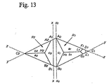
- each pair of the triangular retroreflective elements (R1 and R2) while two bases (y and z) other than the common base (x) shared by the two facing faces (c1 and c2) form a rhombic bottom plane (A 0 -C 1 -B 0 -C 2 ), the common base (x) does not pass through the facing intersections (A 0 and B 0 ) of the rhombic bottom plane but passes through offset points (A 2 and B 2 ).
- the offset i.e., the distance between the segment A 0 -B 0 and the segment A 2 -B 2 is selected appropriately within, for example, a range of from ⁇ 2 to ⁇ 20% of the distance between the other facing intersections (C 1 and C 2 ) of the paired retroreflective elements.
- the heights (hx1 and hx2) of the apices (H1 and H2) from the bottom plane (Sx-Sx') are different, the two facing lateral faces c1 (J 1 -J 2 -K 2 -K 1 -H 1 ) and c2 (J 2 -H 2 -K 2 ) have different shapes, and the face c1 of the retroreflective element (R1) is larger than the face c2 of the other retroreflective element (R2).
- the pair of the triangular cube-corner retroreflective elements according to the present embodiment have substantially the same tilt ( ⁇ ) of their optical axes in directions different at 180°.
- the tilting direction of the optical axis (t1) in one of the paired triangular cube-corner reflective elements (R1) may be such that subtracting a distance (p1) from a distance (q1), i.e., (q1-p1), gives a negative difference, wherein the distance (q1) is a distance from [an intersection (Q1) of the optical axis (t1) and the common bottom plane (S-S')] to [a plane (Lx-Lx') perpendicular to the common bottom plane (S-S') and including the base (x) shared by the pair]; and the distance (p1) is a distance from [an intersection (P1) of the vertical from the apex (H1) of the element down to the common bottom plane (S-S') and the plane (S-S')] to [the vertical plane
- the tilting direction of the optical axis (t2) in the other element (R2), which is different in height from R1, is such that subtracting a distance (p2) from a distance (q2), i.e., (q2-p2), may give a negative difference, wherein the distance (q2) is a distance from [an intersection (Q2) of the optical axis (t2) and the common bottom plane (S-S')] to [the plane (Lx-Lx') perpendicular to the common bottom plane (S-S') and including the base (x) shared by the facing lateral faces (c1 and c2) of the pair]; and the distance (p2) is a distance from [an intersection (P2) of the vertical from the apex (H2) of the element down to the common bottom plane (S-S') and the plane (S-S')] to [the vertical plane (Lx-Lx')].
- the optical axes of these elements are tilted in 180° different directions at substantially the same angle ( ⁇ ).
- V-shaped grooves having a substantially symmetrical cross-section intersect with each other to form pairs of triangular cube-comer retroreflective elements, each element of each pair being contoured by three lateral faces (a1, b1 and c1; a2, b2 and c2; ...) which intersect with each other at approximately right angles.
- the lateral faces (c1 and c2) which face each other in each pair have different shapes, and the elements of each pair have different heights (hx1 and hx2) from a common bottom plane (S-S') of the paired triangular retroreflective elements (R1 and R2) to their respective apices (H1 and H2).
- the height from a bottom plane (S-S') including the bases (z, z) of one of the lateral faces (a1 and a2) and the bases (y, y) of the other lateral faces (b1 and b2) of the paired triangular retroreflective elements to the apex (H1), being taken as hyz1 are equal
- the height (hx1) from the bottom plane (Sx-Sx') to the apex (H1) is larger than the height (hx2) from the bottom plane (Sx-Sx') to the other apex (H2).
- V-shaped grooves having a substantially symmetrical cross-section intersect with each other to form pairs of triangular cube-corner retroreflective elements, each element of each pair being contoured by three lateral faces (a1, b1 and c1; a2, b2 and c2; ...) which intersect with each other at approximately right angles, wherein the paired elements (R1 and R2) in each pair are substantially similar in optical geometry such that their respective optical axes make substantially the same angle ( ⁇ ) with the vertical in 180° different directions.
- each pair of the triangular retroreflective elements of this embodiment while two bases (y and z) other than the common base (x) shared by the two facing lateral faces (c1 and c2) form a rhombic bottom plane (A 0 -C 1 -B 0 -C 2 ), the common base (x) does not pass through the facing intersections (A 0 and B 0 ) of the rhombic bottom plane but passes through offset points (A 2 and B 2 ).
- the offset i.e., the distance between the segment A 0 -B 0 and the segment A 2 -B 2 is selected appropriately within, for example, a range of from ⁇ (2 to 20)% of the distance between the other facing intersections (C 1 and C 2 ).
- the heights (hx1 and hx2) of the apices (H1 and H2) from the bottom plane (S-S') common to the two elements (R1 and R2) are different, and the two facing lateral faces c1 (A 2 -B 2 -H 1 ) and c2 (A 2 -H 2 -B 2 ) have different shapes and areas.
- the paired triangular cube-corner retroreflective elements have their optical axes tilted at substantially the same angle ( ⁇ ) but in directions 180° different.
- the tilting direction of the optical axis (t1) in one of the paired triangular reflective elements (R1) is such that subtracting a distance (p1) from a distance (q1), i.e., (q1-p1), gives a positive difference, wherein the distance (q1) is a distance from [an intersection (Q1) of the optical axis (t1) and the common bottom plane (S-S')] to [a plane (Lx-Lx') perpendicular to the common bottom plane (S-S') and including the base (x) shared by the pair]; and the distance (p1) is a distance from [an intersection (P1) of the vertical from the apex (H1) of the element down to the common bottom plane (S-S') and the plane (S-S')] to [the vertical plane (Lx-Lx
- the tilting direction of the optical axis (t2) in the other element (R2), which is different in height from R1 is such that subtracting a distance (p2) from a distance (q2), i.e., (q2-p2), gives a positive difference, wherein the distance (q2) is a distance from [an intersection (Q2) of the optical axis (t2) and the common bottom plane (S-S')] to [the plane (Lx-Lx') perpendicular to the common bottom plane (S-S') and including the base (x) shared by the pair]; and the distance (p2) is a distance from [an intersection (P2) of the vertical from the apex (H2) of the element down to the common bottom plane (S-S') and the plane (S-S')] to [the vertical plane (Lx-Lx')].
- the optical axes of these elements are tilted in 180° different directions at substantially the same angle ( ⁇ ).
- V-shaped grooves having a substantially symmetrical cross-section intersect with each other so that pairs of triangular cube-corner retroreflective elements projecting over a common bottom plane (S-S') are arranged in a closest-packed configuration, each element of each pair being contoured by three lateral faces (a1, b1 and c1; a2, b2 and c2; ...) which intersect with each other at approximately right angles.
- the lateral faces (c1 and c2) which face each other in each pair make a pair sharing a base (x).
- the common bottom plane (S-S') is a common plane including both the bases (z, z) of one of the lateral faces (a1 or a2) and the bases (y, y) of the other lateral faces (b1 or b2).
- the lateral faces (c1 and c2) facing each other have different shapes, and the two apices have different heights (hx1 and hx2) from the common bottom plane (S-S').
- a large number of bases (x, x, x, ...) of V-shaped grooves do not agree with a large number of lines (x0, x0, x0, ...) passing through the facing intersections of a rhombic bottom plane formed of the other two bases (y and z) but pass through offset positions.
- the offset positions assigned for the bases (x, x, x, ...) of the V-shaped grooves are alternately at the right-hand side and the left-hand side of the respective lines (x0, x0, x0, .
- the triangular cube-corner retroreflective sheeting having the above-described configuration is optically uniform in the right-to-left direction.
- Retroreflection performance of a retroreflective sheet 100 mm wide and 100 mm long was measured according to the test method specified in JIS Z-9117 by using Model 920 supplied by Advanced Retro Technology, Inc. as an instrument for measuring retroreflectivity. Measurement was made on appropriately selected five points of the sheet at an observation angle of 0.2° and an entrance angle of 5°, and an average value of the results was taken as retroreflection performance of the retroreflective sheet.
- the hue of a disk of a retroreflective sheet having a diameter of 50 mm was measured on appropriately selected five points with a colorimeter SE-2000 supplied by Nippon Denshoku Industries Co., Ltd. in accordance with JIS Z-9117. The colors were specified by XYZ tristimulus system. An averaged Y value was taken as a hue (brightness) of the retroreflective sheet.
- a weathering test was carried out with a weathering tester CXW-B-812501500 available from Atlas Electric Device Company in accordance with JIS Z-9117 except that the exposure time was 3000 hours.
- Parallel grooves having a 100 ⁇ m deep V-shaped cross-section were cut in a flat ground surface of a 100-mm square brass plate in two directions intersecting at 58.76° at a pitch of 210.88 ⁇ m in each direction in a repetitive pattern. Cutting was made by a fly-cutting technique using a diamond cutting tool having a tip angle of 68.53°.
- Parallel grooves having a 100 ⁇ m deep V-shaped cross-section were then cut in a third direction intersecting at an angle of 60.92° with the first and the second directions at a pitch of 214.92 ⁇ m with a diamond cutting tool having a tip angle of 71.52° thereby to form a mother matrix of the brass plate having a large number of triangular cube-corner projections having a height of 100 ⁇ m in a closest-packed configuration.
- the resulting triangular reflective elements had their optical axes tilted at +1°. All the interfacial angles of the three lateral faces constituting each pyramid were 90°.
- a 1.0 mm thick mold for cube corners having inverted cavities was made of nickel by electroforming using the brass-made matrix.
- the following ink formulation was mixed by stirring in a bead mill for 5 hours to prepare white ink having a solids content of 19%.
- the binder used was prepared by polymerizing 99 parts by weight each of butyl acrylate, acrylic acid and vinyl acetate using a 1:1 mixed solvent of toluene and ethyl acetate and benzoyl peroxide as an initiator to a number average molecular weight of 990,000.
- the binder thus obtained had a solid content of 50% by weight.
- Ink binder 100 parts by weight Epoxidized soybean oil 0.5 part by weight Titanium oxide 1.5 parts by weight Precipitated barium sulfate 1 part by weight Antifoaming agent 0.1 part by weight Methyl ethyl ketone 80 parts by weight Toluene 50 parts by weight Ethyl acetate 45 parts by weight
- a pattern of dots having a diameter of 2 mm arranged in zig-zag lines at a pitch of 4 mm as shown in Fig. 4 was printed on a 70 ⁇ m thick acrylic resin film (Sunduren, available from Kaneka Corp.) by gravure printing using the above-described printing ink.
- the thickness of the printed areas was about 2 ⁇ m.
- the printed acrylic film was superposed, with the printed side inward, on a 200 ⁇ m thick polycarbonate resin sheet (Iupilon Sheet H3000, available from Mitubishi Engineering-Plastics Corp.) and hot-pressed through a pair of laminating rolls under conditions of 200°C and 30 kg/m to obtain a printed laminate sheet.
- a 200 ⁇ m thick polycarbonate resin sheet Iupilon Sheet H3000, available from Mitubishi Engineering-Plastics Corp.
- the printed laminate sheet was compression molded by using the above-prepared mold at a molding temperature of 200°C under a molding pressure of 50 kg/m. After cooling to 30°C while applying the pressure, the resin sheet was taken out to obtain a printed triangular cube-corner retroreflective sheet precursor (hereinafter simply referred to as a precursor) having on the surface thereof an about 170 ⁇ m thick holding body layer with cube corners arranged in a closest-packed configuration (not shown).
- a precursor printed triangular cube-corner retroreflective sheet precursor having on the surface thereof an about 170 ⁇ m thick holding body layer with cube corners arranged in a closest-packed configuration (not shown).
- the precursor was sealed with a 38 ⁇ m thick thermoplastic polyester resin film provided on a 50 ⁇ m thick white polyethylene terephthalate film by use of a sealing mold having a projecting honeycomb structure.
- an acrylic pressure-sensitive adhesive Netsu KP1818, available from Nippon Carbide Industries, Co., Inc.
- a 100 ⁇ m thick polypropylene release sheet available from Okura Industrial Co., Ltd.
- the precursor prepared in Example 1 was set in a vacuum deposition system having a vacuum chamber capable of maintaining a vacuum degree of 9 x 10 -4 mmHg and a heating unit capable of melting aluminum in a graphite crucible in the vacuum chamber by an electric heater.
- Pure aluminum pellets having a purity of 99.99% or higher and particulate metallic titanium were put in the graphite crucible at a weight ratio of 100:1, and vaporized and deposited on the three slant surfaces of the triangular cube-corner reflective elements at an alternating voltage of 3500 V and a current of 115 to 120 A for a batch treating time of 5 minutes, thereby to form an aluminum deposit layer having a thickness of 1100 ⁇ as a mirror-reflection layer.
- a pressure-sensitive adhesive layer and a release sheet were superposed on the vapor-deposited side of the vapor-deposited stock sheeting in the same manner as in Example 1 to prepare a vapor-deposited triangular cube-corner retroreflective sheet having a printed layer.
- a pattern of dots having a diameter of 1 mm arranged in zig-zag lines at a pitch of 3 mm as shown in Fig. 4 was formed on the polycarbonate side of the laminate sheet by gravure printing with the printing ink prepared in Example 1.
- the thickness of the printed areas was about 2 ⁇ m.
- the printed laminate sheet was compression molded with its printed side in contact with the mold under the same conditions as in Example 1.
- a sealed structure and an adhesive layer were introduced in the same manner as in Example 1 to prepare a vapor-deposited triangular cube-corner retroreflective sheet in which the prism reflective surface was partly printed in white.
- a triangular cube-corner retroreflective sheet having a printed layer was prepared in the same manner as in Example 1, except that the printed layer had the pattern shown in Fig. 6.
- a triangular cube-corner retroreflective sheet having a printed layer was prepared in the same manner as in Example 2, except that the printed layer had the pattern shown in Fig. 6.
- Example 1 Example 2
- Example 3 Comparative Example 1 Comparative Example 2
- Retroreflection Performance 430 615 512 457 534 Hue (Y Value) 46 28 25 48 28 Appearance after Weathering Test nothing abnormal nothing abnormal nothing abnormal lifting of printed parts lifting of printed parts
- the retroreflective sheeting according to the present invention has excellent resistance to weather and water and an improved hue and is particularly useful for signs such as road signs and construction signs; license plates of vehicles such as automobiles and motorcycles; safety equipment such as garments and lifesaving equipment; markings of signboards; and reflectors such as visible light, laser light or infrared light reflective sensors; and the like.
Abstract
Description
- The present invention relates to retroreflective sheeting having a printed layer, particularly a triangular cube-comer retroreflective sheeting constituted of triangular cube-corner retroreflective elements (hereinafter also referred to simply as triangular reflective elements) which is characterized by having a printed layer for tone improvement in a part thereof and is useful for signs such as road signs and construction signs; license plates of vehicles such as automobiles and motorcycles; safety equipment such as garments and lifesaving equipment; markings of signboards; and reflectors such as visible light, laser light or infrared light reflective sensors; and the like.
- Retroreflective sheeting which reflects incident light toward the light source has been well known. The sheeting having such retroreflective properties has been used widely in the above-described fields. In particular, cube-comer retroreflective sheeting making use of the retroreflection theory of cube-corner retroreflective elements such as triangular reflective elements and triangular cube-comer retroreflective sheeting having a vapor-deposition layer on the lateral faces of the triangular reflective elements thereof (hereinafter referred to as vapor-deposited triangular cube-corner retroreflective sheeting) are extremely superior in retroreflectivity to conventional retroreflective sheetings using micro glass beads and have been extending their use year by year because of their excellent retroreflective performance.
- Such retroreflective sheetings and processes for producing them are described, e.g., in U.S. Patent 3,417,959 and WO98/18028 as to triangular cube-corner retroreflective sheeting, and JP-A-49-106839 (U.S. Patent 3,712,706) as to vapor-deposited triangular cube-corner retroreflective sheeting.
- Vapor-deposited triangular cube-corner retroreflective sheeting has a disadvantage attributed to its retroreflective elements that the appearance is darkened by the influence of the metal color.
- In order to improve the hue of the triangular cube-corner retroreflective sheeting and the vapor-deposited triangular cube-corner retroreflective sheeting, it has been attempted to provide a continuous printed layer in part of the retroreflective sheeting.
- However, because a printed layer has slightly poor adhesion to both the reflective element layer and a surface protective layer and also has poor weatherability, it is liable to suffer lifting in a weathering test. It also has a disadvantage of easily absorbing water. Where a continuous printed layer is provided in a triangular cube-corner retroreflective sheeting or a vapor-deposited triangular cube-corner retroreflective sheeting, the sheeting has poor adhesion around the printed layer and poor weather resistance or water resistance.
- In addition to the above-described triangular cube-comer retroreflective sheeting and vapor-deposited retroreflective sheeting, retroreflective sheetings include those using micro glass beads, such as encapsulated retroreflective sheeting and encapsulated lens retroreflective sheeting.
- The encapsulated retroreflective sheeting comprises a light-transmitting support layer, a microbead layer provided opposite to the light incident side of the light-transmitting support layer in which a large number of micro glass beads are arrayed substantially in a monolayer with their almost semi-spherical portions being embedded, a light-transmitting focusing layer which is formed along the surface of the other non-embedded semi-spherical portions of the micro glass beads and has such a thickness that the micro glass beads may substantially focus on the surface of the focusing layer that is not in contact with the micro glass beads, and a light-reflective metal film which is formed on the surface of the focusing layer that is not in contact with the micro glass beads. If necessary, the sheeting can have a light-transmitting surface protective layer superposed on the surface of the light-incident side of the support layer.
- The encapsulated lens retroreflective sheeting comprises a light-transmitting coating layer, a support layer, a lens retroreflective element layer provided on the surface of the support layer which faces the light-transmitting coating layer in which a large number of micro glass beads are arrayed substantially in a monolayer with their almost semi-spherical portions being embedded and with the embedded semi-spherical portions being coated with a light-reflective metal film, and an air layer provided between the light-transmitting coating layer and the lens retroreflective elements. The air layer is formed by partly connecting the light-transmitting coating layer and the support layer via joints such that gaps are formed between these layers, and the air layer is partitioned by the joints into a large number of closed small vacant spaces.
- The encapsulated retroreflective sheeting and the encapsulated lens retroreflective sheeting essentially have lower retroreflective performance than the. triangular cube-corner retroreflective sheeting or the vapor-deposited triangular cube-corner retroreflective sheeting. Therefore, where a printed layer is provided, they are incapable of satisfying the requirement for retroreflective performance.
- In the light of the disadvantages of the conventional techniques, the present invention provides retroreflective sheeting with an improved hue by a very simple and inexpensive method.
- The inventors of the present invention have conducted extensive investigation on hues of triangular cube-corner retroreflective sheeting or vapor-deposited triangular retroreflective sheeting. As a result, they have found that disposing a specific printed layer on the reflective element layer or the surface protective layer of the retroreflective sheeting provides retroreflective sheeting with excellent weather resistance and water resistance and an improved hue and thus have completed the present invention.
- The present invention provides retroreflective sheeting having a printed layer which comprises at least a reflective element layer made up of a large number of reflective elements and a holding body layer and a surface protective layer provided on the reflective element layer, which is characterized in that the printed layer is provided on the lateral faces of the reflective elements or between the holding body layer and the surface protective layer or on the surface protective layer, the printed layer is formed of a discrete repetitive pattern of unit patterns, and the unit patterns each have an area of 0.15 mm2 to 30 mm2.
-
- Fig. 1 is a cross-section of an example of the triangular cube-corner retroreflective sheeting according to the present invention, in which a printed layer is provided between a holding body layer and a surface protective layer.
- Fig. 2 is a cross-section of an example of the vapor-deposited triangular cube-comer retroreflective sheeting according to the present invention, in which a printed layer is provided between a holding body layer and a surface protective layer.
- Fig. 3 is a cross-section of another example of the vapor-deposited triangular cube-corner retroreflective sheeting according to the present invention, in which a printed layer is provided on the lateral faces of reflective elements.
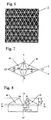
- Fig. 4 is a plan view showing an example of printed pattern units and their configurations in a printed layer used in the present invention.
- Fig. 5 is a plan view showing another example of printed pattern units and their configurations in a printed layer used in the present invention.
- Fig. 6 is a plan view showing an example of a conventionally used printed layer having a continuous printed area.
- Fig. 7 is a plan view of an example of a pair of triangular cube-corner retroreflective elements used in the present invention.
- Fig. 8 is a side view of the pair of reflective elements shown in Fig. 7.
- Fig. 9 is a plan view of a group of triangular cube-corner retroreflective elements made up of the pairs of reflective elements shown in Fig. 7.
- Fig. 10 is a side view of the group of triangular cube-comer retroreflective elements shown in Fig. 9.
- Fig. 11 is a plan view of an example of a group of triangular cube-comer retroreflective elements used in the present invention.
- Fig. 12 is a side view of the group of triangular cube-corner retroreflective elements shown in Fig. 11.
- Fig. 13 is an enlarged plan view of a pair of reflective elements out of the group of triangular cube-corner retroreflective elements shown in Fig. 11.
- Fig. 14 is a side view of the pair of reflective elements shown in Fig. 13.
- Fig. 15 is a plan view of another example of a group of triangular cube-corner retroreflective elements used in the present invention.
- Fig. 16 is an enlarged plan view of a pair of reflective elements out of the group of triangular cube-corner retroreflective elements shown in Fig. 15.
- Fig. 17 is a side view of the pair of reflective elements shown in Fig. 16.
- Fig. 18 is a plan view of still another example of a group of triangular cube-corner retroreflective elements used in the present invention.
- Fig. 19 is an enlarged plan view of a pair of reflective elements out of the group of triangular cube-corner retroreflective elements shown in Fig. 18.
- Fig. 20 is a side view of the pair of reflective elements shown in Fig. 19.
- Fig. 21 is a plan view of yet another example of a group of triangular cube-corner retroreflective elements used in the present invention.
-
- The retroreflective sheeting having a printed layer according to the present invention will be described in detail with reference to the drawings.
- The retroreflective sheeting of the present invention is preferably a triangular cube-corner retroreflective sheeting or vapor-deposited triangular cube-corner retroreflective sheeting each having at least a reflective element layer made up of a large number of reflective elements and a holding body layer and a surface protective layer provided on the reflective element layer. Retroreflective sheetings of these kinds exhibit particularly excellent retroreflective performance so that sufficient retroreflectivity can be obtained even in the presence of a printed layer.
- The reflective element layer made up of a large number of reflective elements and a holding body layer can be of the type known as a reflective element layer of triangular cube-corner retroreflective sheeting or vapor-deposited triangular cube-corner retroreflective sheeting.
- An example of the triangular cube-corner retroreflective sheeting according to the present invention will be described by referring to Fig. 1. Fig. 1 is a cross-section of an example of the triangular cube-corner retroreflective sheeting according to the present invention, in which a printed layer is provided between a holding body layer and a surface protective layer.
- In Fig. 1, numeral (1) indicates a surface protective layer; (2) a printed layer for coloring for hue adjustment; (5) a reflective element layer having triangular reflective elements (4) arrayed in a closest-packed configuration; and (3) a holding body layer which holds the reflective elements (4). Arrow (11) shows the direction of incident light. The reflective elements (4) and the holding body layer (3) which constitute the reflective element layer (5) are generally formed by integral molding but may be molded separately and joined together. According to the intended use and the environment of use of the retroreflective sheeting of the present invention, it can further comprise a binder layer (7) making a sealed structure for preventing water from penetrating to the back of the reflective element layer (5), a support layer (8) supporting the binder layer (7), an adhesive layer (9) for sticking the retroreflective sheeting to an adherend structure, and a releasable sheet (10).
- As shown in Fig. 1, the triangular cube-corner retroreflective sheeting usually has an air layer (6) on the back of the triangular cube-comer retroreflective elements to increase the critical angle for total internal reflection of the reflective element layer (5). In order to avoid such problems as a reduction in critical angle due to water penetration under conditions of use, it is preferred that the reflective element layer (5) and the support layer (8) be sealed by the binder layer (7).
- The sealing can be carried out by the methods described in U.S. Patents 3,190,178 and 4,025,159, JP-A-U-50-28669, etc.
- The printed layer (2) is provided on the lateral faces of the reflective elements (4) or between the holding body layer (3) and the surface protective layer (1) or on the surface protective layer (1). Where the surface protective layer (1) is composed of two or more layers, the printed layer (2) can be provided between the protective layers.
- The printed layer (2) can be usually provided by the methods of gravure printing, screen printing, ink jet printing and the like.
- Printed areas of the printed layer (2) should be discrete. For example, it is formed of a repetitive pattern of discrete unit patterns as shown in Figs. 4 or 5.
- The unit patterns are not limited to those illustrated in Figs. 4 and 5 and include figures, such as ellipses, squares and rectangles, geometric patterns composed of straight lines or curved lines, letters, symbols, and combinations of two or more of these units.
- The unit pattern has an area of 0.15 mm2 to 30 mm2, preferably 0.2 mm2 to 25 mm2, still preferably 0.4 mm2 to 15 mm2.
- A unit pattern area of 0.15 mm2 or more secures excellent pattern formability and facilitates hue control. A unit pattern area of 30 mm2 or less does not cause a reduction in adhesion strength between two layers around the areas having the printed layer (2) therebetween.
- While the unit patterns can be arranged at any intervals as long as each unit pattern forms an independent area, they are preferably arranged so that non-printed areas among them may have a minimum width of 0.2 mm to 200 mm, particularly 0.5 mm to 50 mm.
- The printed layer (2) preferably has a total printed area of 2% to 70%, particularly 5% to 40%, based on the area of the surface layer of the retroreflective sheeting.
- The thickness of the printed layer (2) is preferably, but is not limited to, 0.5 to 10 µm, still preferably 1 to 5 µm, particularly preferably 2 to 4 µm. With a thickness of 0.5 µm or greater, excellent formability of the printed layer (2) is secured, and hue control is easy. With a thickness of 10 µm or smaller, the printed layer (2) does not cause a reduction in adhesion strength between two layers around the areas having the printed layer (2) therebetween.
- Ink for forming the printed layer (2) comprises a resin component and a colorant and, if desired, various additives, such as a plasticizer, an antifoaming agent, a leveling agent, an ultraviolet absorber, a light stabilizer, a heat stabilizer, and a crosslinking agent. It can further contain a solvent for viscosity adjustment or a like purpose.
- The resin component which can be used in the ink preferably includes, but is not limited to, melamine resins, epoxy resins, urethane resins, vinyl resins, polyester resins and alkyd resins, which are excellent in dispersing properties for colorants, dispersion stability, dissolving properties for solvents, weather resistance, printability, adhesion to films, and the like. They can be used either individually or in the form of a copolymer of two or more thereof.
- Where the surface protective layer (1) is made of a vinyl chloride resin or a (meth)acrylic resin, preferred among the above-recited resin components for the ink are an acrylic resin, a vinyl resin or a copolymer thereof.
- While not limiting, the colorant used in the ink is preferably such that the hue is brightened and that hiding properties are obtained. Light colors matching the sheeting's hue are preferred. For example, white organic pigments, white or yellow inorganic pigments, fluorescent dyes or fluorescent whitening agents are useful. White or yellow inorganic pigments are particularly preferred for their excellent hiding properties.
- The organic pigments include Fast Yellow, Disazo Yellow, Permanent Yellow, Lionol Yellow, Chromophthal Yellow, and Irgazin Yellow. They can be used either individually or as a combination thereof.
- The inorganic pigments include white ones, such as titanium oxide, calcium carbonate, barium sulfate, zinc oxide, and zinc sulfide; and yellow ones, such as titanium yellow, and yellow iron oxide. They can be used either individually or as a combination thereof or in combination with the above-described organic pigments.
- Materials for forming the reflective elements (4) and the holding body layer (3) are not particularly limited as far as flexibility, one of the objects of the present invention, is secured. Materials having optical transparency and uniformity are preferred.
- Materials which can be used to form the reflective elements (4) include polycarbonate resins, vinyl chloride resins, (meth)acrylic resins, epoxy resins, styrene resins, polyester resins, fluorine resins, olefin resins such as polyethylene resins and polypropylene resins, cellulosic resins, and urethane resins. Ultraviolet absorbers, light stabilizers, antioxidants, etc. can be used either individually or as a combination thereof to improve weather resistance. Further, various organic pigments, inorganic pigments, fluorescent pigments, dyes, fluorescent dyes, and so forth can be incorporated as colorants.
- Materials for making the surface protective layer (1) include those described above as being useful to make the reflective elements (4). In particular, vinyl chloride resins and (meth)acrylic resins which are excellent in weather resistance, solvent resistance, printability and the like are preferred. Ultraviolet absorbers, light stabilizers, antioxidants, etc. may also be incorporated into the surface protective layer (1) either individually or as a combination to improve weather resistance. Further, various organic pigments, inorganic pigments, fluorescent pigments, dyes, fluorescent dyes, and the like may also be incorporated as colorants.
- Where the printed layer (2) is printed on the surface protective layer (1), the surface tension of the surface protective layer (1) is preferably adjusted to 32 dyne/cm or more to have improved printability.
- Resins which can be used in the binder layer (7) include (meth)acrylic resins, polyester resins, alkyd resins, and epoxy resins. For bonding, known methods such as a thermally fusible resin bonding method, a thermosetting resin bonding method, an ultraviolet-curing resin bonding method, and an electron radiation-curing resin bonding method, can be adopted.
- The binder layer (7) can be applied either onto the entire surface of the support layer (8) or on selected areas to be joined with the reflective elements (4) by printing or a like method.
- Materials which can form the support layer (8) include those recited above as usable for the reflective elements (4) and other general film-forming resins, fiber, fabric, and metal foils or plates of stainless steel, aluminum, etc. They can be used either individually or as a combination thereof.
- The adhesive layer (9) which is used to stick the retroreflective sheeting of the present invention onto a metal plate, a wooden plate, a glass plate, a plastic plate, etc. and the releasable sheet (10) for the adhesive layer (9) are selected appropriately from those known. The adhesive is selected appropriately from pressure-sensitive adhesives, heat-sensitive adhesives, crosslinking adhesives, and the like. The pressure-sensitive adhesives include polyacrylic ester types prepared by copolymerizing an acrylic ester, e.g., butyl acrylate, 2-ethylhexyl acrylate, isooctyl acrylate or nonyl acrylate, with acrylic acid, vinyl acetate, etc.; silicone types, and rubber types. The heat-sensitive adhesives include acrylic types, polyester types, and epoxy resin types.
- An example of the vapor-deposited triangular cube-comer retroreflective sheeting according to the present invention will then be described by referring to Figs. 2 and 3. Fig. 2 is a cross-section of an example of the vapor-deposited triangular cube-corner retroreflective sheeting according to the present invention, in which a printed layer is provided between a holding body layer and a surface protective layer. Fig. 3 is a cross-section of another example of the vapor-deposited triangular cube-corner retroreflective sheeting according to the present invention, in which a printed layer is provided on the lateral faces of reflective elements.
- A surface protective layer (1), a printed layer (2), a holding body layer (3), reflective elements (4), a reflective element layer (5), an adhesive layer (9), and a releasable sheet (10) which constitute the vapor-deposited triangular cube-corner retroreflective sheeting can be the same as those used in the above-mentioned triangular cube-corner retroreflective sheeting.
- The vapor-deposited triangular cube-comer retroreflective sheeting has a metallic mirror-reflection layer (12) deposited on the lateral faces of the reflective elements (4). It has the adhesive layer (9) in direct contact with the mirror-reflection layer (12). Since the vapor-deposited triangular cube-corner retroreflective sheeting according to this embodiment achieves retroreflection through the mirror reflection theory, an air layer is not needed. As a result, neither a binder layer nor a support layer is required.
- In the vapor-deposited triangular cube-corner retroreflective sheeting according to the present invention, the mirror-reflection layer (12) made of a metal such as aluminum, copper, silver or nickel is deposited on the lateral faces of the reflective elements (4) by vacuum deposition, chemical plating, sputtering or a like technique. Of these techniques for depositing the mirror-reflection layer (12) vacuum deposition using aluminum is preferred; for the deposition temperature can be lowered to minimize thermal deformation of the reflective elements (4) during vapor deposition, and the resulting mirror-reflection layer (12) has a bright tone.
- A continuous vapor deposition system for forming the aluminum mirror-reflection layer (12) comprises a vacuum chamber capable of keeping a vacuum degree of about 7 to 9 x 10⁻⁴ mmHg, an unwinder for feeding prism stock sheeting made up of a substrate and a surface protective layer superposed on the light incident side of the substrate, the unwinder being set in the vacuum chamber, a winder for taking up the prism stock sheeting having a deposit layer thereon, and a heating unit disposed between the unwinder and the winder in which aluminum in a graphite crucible is melted by means of an electric heater. Pure aluminum pellets having a purity of 99.99% by weight or more are put into the graphite crucible. The aluminum is melted and vaporized under conditions of 350 to 360 V in alternating voltage, 115 to 120 A in current and deposited on the surface of the reflective elements at a treating rate of 30 to 70 m/min to form the mirror-reflection layer (12) to a thickness, e.g., of 800 to 2000 Å.
- The reflective elements (4) of the triangular cube-corner retroreflective sheeting and the vapor-deposited triangular cube-corner retroreflective sheeting according to the present invention preferably include the following triangular cube-corner retroreflective elements (1) and (2).
- (1) Triangular cube-comer retroreflective elements having the configurations shown
in Figs. 11 through 21, wherein
the triangular cube-corner retroreflective elements are pairs of triangular cube-corner retroreflective elements formed by V-shaped grooves having a substantially symmetrical cross-section and intersecting with each other so that the pairs project over a common bottom plane (S-S') and are arranged in a closest-packed configuration and that each element of each pair is contoured by three lateral faces (a1, b1 and c1; a2, b2 and c2; ...) which intersect with each other at approximately right angles,
two lateral faces facing each other (c1 and c2) in each pair make a pair sharing a base (x),
the bottom plane (S-S') is a common plane including both the base (z, z) of one of the other lateral faces (a1 or a2) and the base (y, y) of the other lateral faces (b1 or b2),
the lateral faces (c1 and c2) facing each other and having the common base (x) in each pair have different shapes,
and the elements of each pair have different heights from the bottom plane (S-S') to their respective apices. - (2) Triangular cube-corner retroreflective elements having the configuration shown
in Figs. 7 through 10, wherein
pairs of triangular cube-corner retroreflective elements projecting over a common bottom plane (Sx-Sx') are arranged in a closest-packed configuration, each pair sharing a base on the common bottom plane (Sx-Sx'),
the bottom plane (Sx-Sx') is a common plane including a large number of bases (x, x, ...) each shared by each pair of triangular reflective elements,
the elements facing each other to make a pair have substantially the same contour and' are substantially symmetrical about a plane (Lx-Lx', Lx-Lx', ...) perpendicular to the bottom plane (Sx-Sx'),
each pair of the triangular reflective elements are formed of slant lateral faces (c1 and c2) which have substantially the same pentagonal shape and share the common base (x, x, ...) as one side of the pentagonal shape and slant lateral faces (a1 and b1) and (a2 and b2) which have substantially the same quadrilateral shape each formed of one of the upper two sides of the face c1 or c2 including the apex (H1 or H2) of each triangular reflective element, share one lateral edge of each element as another side, and intersect with the face c1 or c2 at substantially right angles, and
the height (h') from the apex (H1 or H2) of every triangular reflective element to the bottom plane (Sx-Sx') including the bases (x, x, ...) of the pentagonal slant faces (c1 and c2) is substantially larger than the height (h) from the apex (H1 or H2) of every triangular reflective element to a substantially horizontal plane (imaginary plane; S-S') including the bases (y and z) of the other slant faces (a1and b1) and (a2, and b2). -
- Sheeting having the triangular cube-corner retroreflective elements (2) is described in WO98/18028, which is referred to for the details.
- The triangular cube-corner retroreflective elements (1) shown in Figs. 11 to 21 are described below in greater detail. The triangular cube-comer retroreflective elements of the embodiment shown in Figs. 11 to 14 are described first.
- As shown in Fig. 11, V-shaped grooves having a substantially symmetrical cross-section intersect with each other so that pairs of triangular cube-comer retroreflective elements projecting over a common bottom plane (S-S') are arranged in a closest-packed configuration, each element of each pair being contoured by three lateral faces (a1, b1 and c1; a2, b2 and c2; ...) which intersect with each other at approximately right angles. In each pair of the triangular retroreflective elements, two lateral faces facing each other (faces c1 and c2) make a pair sharing a base (x). The bottom plane (S-S') is a common plane including both the base (z, z) of one of the lateral faces (a1 or a2) and the base (y, y) of the other lateral faces (b1 or b2). In each pair of the triangular retroreflective elements sharing the base (x), the lateral faces (c1 and c2) which face each other have different shapes, and the heights (hx1 and hx2) from the bottom plane (S-S') to each apex are different.
- As shown in Fig. 12, the height from a bottom plane (Sx-Sx') including the bases (x, x, ...) shared by facing lateral faces (c1 and c2) in a large number of pairs of the triangular retroreflective elements (R1 and R2) to the apex (H1), being taken as hx1, is larger than the height from the bottom plane (S-S') including the bases (z, z, ...) of one of the lateral faces (a1 and a2) of the paired triangular retroreflective elements and the bases (y, y, ...) of the other lateral faces (b1 and b2) to the apex (H1), being taken as hyz1, and the height hx1 from the bottom plane (Sx-Sx') to the apex (H1) is larger than the height hx2 from the bottom plane (Sx-Sx') to the apex (H2). In this case, the V-shaped grooves forming the bases (x) are preferably made deeper than the V-shaped grooves forming the other bases (y and z) so that the height ratio hx1/hyz1 may range from 1.05 to 1.5.
- As shown in Figs. 13 and 14, V-shaped grooves having a substantially symmetrical cross-section intersect with each other to form pairs of triangular cube-comer retroreflective elements, each element of each pair being contoured by three lateral faces (a1, b1 and c1; a2, b2 and c2; ...) which intersect with each other at approximately right angles, wherein the paired elements in each pair are substantially similar in optical geometry such that their respective optical axes make substantially the same angle () with the vertical in 180° different directions.
- As is apparent from Figs. 13 and 14, the pair of triangular cube-corner retroreflective elements shown in these figures particularly have the following characteristics (1) and (2).
- (1) The bottom plane (S-S') including the bases (z, z, ...) of faces a1 and a2 and the bases (y, y, ...) of faces b1 and b2 of the two retroreflective elements R1 and R2 and the bottom plane (Sx-Sx') including the base (x, x, ...) shared by the facing lateral faces c1 and c2 are not on the same level, the bottom plane (Sx-Sx') being deeper than the bottom plane (S-S').
- (2) An offset is given to the position (x) of the V-shaped groove so that the facing faces c1 and c2 of the two retroreflective elements R1 and R2 may have different areas, the face c1 being larger in area than the face c2.
-
- The paired triangular cube-comer retroreflective elements (R1 and R2) according to this embodiment have their optical axes tilted at substantially the same angle () but in directions 180° different. The tilting direction of the optical axis (t1) of one of the paired elements (R1) is such that subtracting a distance (p1) from a distance (q1), i.e., (q1-p1), gives a positive difference, wherein the distance (q1) is a distance from [an intersection (Q1) of the optical axis (t1) and the common bottom plane (S-S')] to [a plane (Lx-Lx') which is perpendicular to the common bottom plane (S-S') and includes the base (x) shared by the pair]; and the distance (p1) is a distance from [an intersection (P1) of the vertical from the apex (H1) of the element down to the common bottom plane (S-S') and the plane (S-S')] to [the vertical plane (Lx-Lx')]. Likewise, the tilting direction of the optical axis (t2) of the other element (R2), which is different in height from R1, is such that subtracting a distance (p2) from a distance (q2), i.e., (q2-p2), gives a positive difference, wherein the distance q2 is a distance from [an intersection (Q2) of the optical axis (t2) and the common bottom plane (S-S')] to [the plane (Lx-Lx') perpendicular to the common bottom plane (S-S') and including the base (x) shared by the pair]; and the distance (p2) is a distance from [an intersection (P2) of the vertical drawn from the apex (H2) of the element down to the common bottom plane (S-S') and the plane (S-S')] to [the vertical plane (Lx-Lx')]. The optical axes of these elements are tilted in 180° different directions at substantially the same angle ().
- The triangular cube-corner retroreflective elements according the embodiment shown in Figs. 15 to 17 are then described.
- In the triangular cube-corner retroreflective elements according to the embodiment shown in Figs. 15 through 17, V-shaped grooves having a substantially symmetrical cross-section intersect with each other to form pairs of triangular cube-comer retroreflective elements, each element of each pair being contoured by three lateral faces (a1, b1 and c1; a2, b2 and c2; ...) which intersect with each other at approximately right angles, wherein the lateral faces (c1 and c2) which face each other in each pair have different shapes, and the elements of each pair have different heights (hx1 and hx2) from a common bottom plane (S-S') including the bases (z, z) of one of the lateral faces (a1 and a2) and the bases (y, y) of the other lateral faces (b1 and b2) of the paired triangular retroreflective elements to their respective apices (H1 and H2).
- As shown in Fig. 17, the height from a bottom plane (Sx-Sx') including the bases (x, x, ...) each shared by facing lateral faces (C1 and C2) in a pair of the triangular retroreflective elements (R1 and R2) to the apex (H1), being taken as hx1, is smaller than the height from the bottom plane (S-S') including the bases (z, z) of one of the lateral faces (a1 and a2) and the bases (y, y) of the other lateral faces (b1 and b2) of the paired triangular retroreflective elements to the apex (H1), being taken as hyz1, and the height hx1 from the common bottom plane (Sx-Sx') to the apex (H1) is larger than the height hx2 of the other apex (H2). In this case, the V-shaped grooves forming the bases (x) are preferably made shallower than the V-shaped grooves forming the other bases (y and z) so that the height ratio hx1/hyz1 may range from 0.67 to 0.95.
- As shown in Fig. 16, V-shaped grooves having a substantially symmetrical cross-section intersect with each other to form pairs of triangular cube-corner retroreflective elements, each element of each pair being contoured by three lateral faces (a1, b1 and c1; a2, b2 and c2; ...) which intersect with each other at approximately right angles. The paired elements in each pair are substantially similar in optical geometry such that their respective optical axes make substantially the same angle () with the vertical in 180° different directions.
- In each pair of the triangular retroreflective elements (R1 and R2), while two bases (y and z) other than the common base (x) shared by the two facing faces (c1 and c2) form a rhombic bottom plane (A0-C1-B0-C2), the common base (x) does not pass through the facing intersections (A0 and B0) of the rhombic bottom plane but passes through offset points (A2 and B2). The offset, i.e., the distance between the segment A0-B0 and the segment A2-B2 is selected appropriately within, for example, a range of from ±2 to ±20% of the distance between the other facing intersections (C1 and C2) of the paired retroreflective elements. As a result, the heights (hx1 and hx2) of the apices (H1 and H2) from the bottom plane (Sx-Sx') are different, the two facing lateral faces c1 (J1-J2-K2-K1-H1) and c2 (J2-H2-K2) have different shapes, and the face c1 of the retroreflective element (R1) is larger than the face c2 of the other retroreflective element (R2).
- The pair of the triangular cube-corner retroreflective elements according to the present embodiment have substantially the same tilt () of their optical axes in directions different at 180°. The tilting direction of the optical axis (t1) in one of the paired triangular cube-corner reflective elements (R1) may be such that subtracting a distance (p1) from a distance (q1), i.e., (q1-p1), gives a negative difference, wherein the distance (q1) is a distance from [an intersection (Q1) of the optical axis (t1) and the common bottom plane (S-S')] to [a plane (Lx-Lx') perpendicular to the common bottom plane (S-S') and including the base (x) shared by the pair]; and the distance (p1) is a distance from [an intersection (P1) of the vertical from the apex (H1) of the element down to the common bottom plane (S-S') and the plane (S-S')] to [the vertical plane (Lx-Lx')] (this mode will hereinafter be referred to as a negative tilt mode of triangular retroreflective elements). Likewise, the tilting direction of the optical axis (t2) in the other element (R2), which is different in height from R1, is such that subtracting a distance (p2) from a distance (q2), i.e., (q2-p2), may give a negative difference, wherein the distance (q2) is a distance from [an intersection (Q2) of the optical axis (t2) and the common bottom plane (S-S')] to [the plane (Lx-Lx') perpendicular to the common bottom plane (S-S') and including the base (x) shared by the facing lateral faces (c1 and c2) of the pair]; and the distance (p2) is a distance from [an intersection (P2) of the vertical from the apex (H2) of the element down to the common bottom plane (S-S') and the plane (S-S')] to [the vertical plane (Lx-Lx')]. The optical axes of these elements are tilted in 180° different directions at substantially the same angle ().
- The triangular cube-corner retroreflective elements according the embodiment shown in Figs. 18 to 20 are then described.
- In the triangular cube-corner retroreflective elements according to the embodiment shown in Figs. 18 through 20, V-shaped grooves having a substantially symmetrical cross-section intersect with each other to form pairs of triangular cube-comer retroreflective elements, each element of each pair being contoured by three lateral faces (a1, b1 and c1; a2, b2 and c2; ...) which intersect with each other at approximately right angles. The lateral faces (c1 and c2) which face each other in each pair have different shapes, and the elements of each pair have different heights (hx1 and hx2) from a common bottom plane (S-S') of the paired triangular retroreflective elements (R1 and R2) to their respective apices (H1 and H2).
- As shown in Fig. 20, the height from a bottom plane (Sx-Sx') including the base (x) shared by facing lateral faces (c1 and c2) in a pair of the triangular retroreflective elements (R1 and R2) to the apex (H1), being taken as hx1, and the height from a bottom plane (S-S') including the bases (z, z) of one of the lateral faces (a1 and a2) and the bases (y, y) of the other lateral faces (b1 and b2) of the paired triangular retroreflective elements to the apex (H1), being taken as hyz1, are equal, and the height (hx1) from the bottom plane (Sx-Sx') to the apex (H1) is larger than the height (hx2) from the bottom plane (Sx-Sx') to the other apex (H2).
- As shown in Fig. 19, in this embodiment, V-shaped grooves having a substantially symmetrical cross-section intersect with each other to form pairs of triangular cube-corner retroreflective elements, each element of each pair being contoured by three lateral faces (a1, b1 and c1; a2, b2 and c2; ...) which intersect with each other at approximately right angles, wherein the paired elements (R1 and R2) in each pair are substantially similar in optical geometry such that their respective optical axes make substantially the same angle () with the vertical in 180° different directions.
- In each pair of the triangular retroreflective elements of this embodiment, while two bases (y and z) other than the common base (x) shared by the two facing lateral faces (c1 and c2) form a rhombic bottom plane (A0-C1-B0-C2), the common base (x) does not pass through the facing intersections (A0 and B0) of the rhombic bottom plane but passes through offset points (A2 and B2). The offset, i.e., the distance between the segment A0-B0 and the segment A2-B2 is selected appropriately within, for example, a range of from ±(2 to 20)% of the distance between the other facing intersections (C1 and C2). As a result, the heights (hx1 and hx2) of the apices (H1 and H2) from the bottom plane (S-S') common to the two elements (R1 and R2) are different, and the two facing lateral faces c1 (A2-B2-H1) and c2 (A2-H2-B2) have different shapes and areas.
- In the pair of triangular cube-comer retroreflective elements of the embodiment shown in Fig. 19, since the V-shaped grooves making the common base (x) shared by the facing surfaces of the two elements and those making other bases (y and z) are cut to make the heights hx1 and hx2 equal, cases are met with in which the other lateral faces (a1 and b1) of the element (R1) are cut off by the V-shaped grooves (y and z) making the lateral faces (a2 and b2) of the other element (R2) thereby forming lateral faces (A0-A2-H1) and (B0-B2-H1) which do not contribute to retroreflection.
- Further, the paired triangular cube-corner retroreflective elements according to this embodiment have their optical axes tilted at substantially the same angle () but in directions 180° different. The tilting direction of the optical axis (t1) in one of the paired triangular reflective elements (R1) is such that subtracting a distance (p1) from a distance (q1), i.e., (q1-p1), gives a positive difference, wherein the distance (q1) is a distance from [an intersection (Q1) of the optical axis (t1) and the common bottom plane (S-S')] to [a plane (Lx-Lx') perpendicular to the common bottom plane (S-S') and including the base (x) shared by the pair]; and the distance (p1) is a distance from [an intersection (P1) of the vertical from the apex (H1) of the element down to the common bottom plane (S-S') and the plane (S-S')] to [the vertical plane (Lx-Lx')]. Likewise, the tilting direction of the optical axis (t2) in the other element (R2), which is different in height from R1, is such that subtracting a distance (p2) from a distance (q2), i.e., (q2-p2), gives a positive difference, wherein the distance (q2) is a distance from [an intersection (Q2) of the optical axis (t2) and the common bottom plane (S-S')] to [the plane (Lx-Lx') perpendicular to the common bottom plane (S-S') and including the base (x) shared by the pair]; and the distance (p2) is a distance from [an intersection (P2) of the vertical from the apex (H2) of the element down to the common bottom plane (S-S') and the plane (S-S')] to [the vertical plane (Lx-Lx')]. The optical axes of these elements are tilted in 180° different directions at substantially the same angle ().
- The triangular cube-corner retroreflective elements according the embodiment shown in Fig. 21 are then described.
- In the triangular cube-corner retroreflective elements according to the embodiment shown in Fig. 21, too, V-shaped grooves having a substantially symmetrical cross-section intersect with each other so that pairs of triangular cube-corner retroreflective elements projecting over a common bottom plane (S-S') are arranged in a closest-packed configuration, each element of each pair being contoured by three lateral faces (a1, b1 and c1; a2, b2 and c2; ...) which intersect with each other at approximately right angles. The lateral faces (c1 and c2) which face each other in each pair make a pair sharing a base (x). The common bottom plane (S-S') is a common plane including both the bases (z, z) of one of the lateral faces (a1 or a2) and the bases (y, y) of the other lateral faces (b1 or b2). In the paired triangular retroreflective elements sharing the base (x), the lateral faces (c1 and c2) facing each other have different shapes, and the two apices have different heights (hx1 and hx2) from the common bottom plane (S-S').
- In the triangular cube-corner retroreflective elements of the embodiment shown in Fig. 21, a large number of bases (x, x, x, ...) of V-shaped grooves do not agree with a large number of lines (x0, x0, x0, ...) passing through the facing intersections of a rhombic bottom plane formed of the other two bases (y and z) but pass through offset positions. The offset positions assigned for the bases (x, x, x, ...) of the V-shaped grooves are alternately at the right-hand side and the left-hand side of the respective lines (x0, x0, x0, ...). As a result, the number of elements with a greater height that are formed on the right side of any one of the lines (x0, x0, x0, ...) and the number of elements with a greater height that are formed on the left side of that line is equal. That is, the triangular cube-corner retroreflective sheeting having the above-described configuration is optically uniform in the right-to-left direction.
- The details of the present invention will further be illustrated more concretely by way of Examples, but it should be understood that the present invention is not deemed to be limited thereto.
- The values recited throughout the Description and Claims as well as Examples are as determined by the methods described below.
- Retroreflection performance of a retroreflective sheet 100 mm wide and 100 mm long was measured according to the test method specified in JIS Z-9117 by using Model 920 supplied by Advanced Retro Technology, Inc. as an instrument for measuring retroreflectivity. Measurement was made on appropriately selected five points of the sheet at an observation angle of 0.2° and an entrance angle of 5°, and an average value of the results was taken as retroreflection performance of the retroreflective sheet.
- The hue of a disk of a retroreflective sheet having a diameter of 50 mm was measured on appropriately selected five points with a colorimeter SE-2000 supplied by Nippon Denshoku Industries Co., Ltd. in accordance with JIS Z-9117. The colors were specified by XYZ tristimulus system. An averaged Y value was taken as a hue (brightness) of the retroreflective sheet.
- A weathering test was carried out with a weathering tester CXW-B-812501500 available from Atlas Electric Device Company in accordance with JIS Z-9117 except that the exposure time was 3000 hours.
- The results of the above measurements are shown in Table 1.
- Preparation of mold:
- Parallel grooves having a 100 µm deep V-shaped cross-section were cut in a flat ground surface of a 100-mm square brass plate in two directions intersecting at 58.76° at a pitch of 210.88 µm in each direction in a repetitive pattern. Cutting was made by a fly-cutting technique using a diamond cutting tool having a tip angle of 68.53°.
- Parallel grooves having a 100 µm deep V-shaped cross-section were then cut in a third direction intersecting at an angle of 60.92° with the first and the second directions at a pitch of 214.92 µm with a diamond cutting tool having a tip angle of 71.52° thereby to form a mother matrix of the brass plate having a large number of triangular cube-corner projections having a height of 100 µm in a closest-packed configuration. The resulting triangular reflective elements had their optical axes tilted at +1°. All the interfacial angles of the three lateral faces constituting each pyramid were 90°.
- A 1.0 mm thick mold for cube corners having inverted cavities was made of nickel by electroforming using the brass-made matrix.
- The following ink formulation was mixed by stirring in a bead mill for 5 hours to prepare white ink having a solids content of 19%. The binder used was prepared by polymerizing 99 parts by weight each of butyl acrylate, acrylic acid and vinyl acetate using a 1:1 mixed solvent of toluene and ethyl acetate and benzoyl peroxide as an initiator to a number average molecular weight of 990,000. The binder thus obtained had a solid content of 50% by weight.
Ink binder 100 parts by weight Epoxidized soybean oil 0.5 part by weight Titanium oxide 1.5 parts by weight Precipitated barium sulfate 1 part by weight Antifoaming agent 0.1 part by weight Methyl ethyl ketone 80 parts by weight Toluene 50 parts by weight Ethyl acetate 45 parts by weight - A pattern of dots having a diameter of 2 mm arranged in zig-zag lines at a pitch of 4 mm as shown in Fig. 4 was printed on a 70 µm thick acrylic resin film (Sunduren, available from Kaneka Corp.) by gravure printing using the above-described printing ink. The thickness of the printed areas was about 2 µm.
- The printed acrylic film was superposed, with the printed side inward, on a 200 µm thick polycarbonate resin sheet (Iupilon Sheet H3000, available from Mitubishi Engineering-Plastics Corp.) and hot-pressed through a pair of laminating rolls under conditions of 200°C and 30 kg/m to obtain a printed laminate sheet.
- The printed laminate sheet was compression molded by using the above-prepared mold at a molding temperature of 200°C under a molding pressure of 50 kg/m. After cooling to 30°C while applying the pressure, the resin sheet was taken out to obtain a printed triangular cube-corner retroreflective sheet precursor (hereinafter simply referred to as a precursor) having on the surface thereof an about 170 µm thick holding body layer with cube corners arranged in a closest-packed configuration (not shown).
- The precursor was sealed with a 38 µm thick thermoplastic polyester resin film provided on a 50 µm thick white polyethylene terephthalate film by use of a sealing mold having a projecting honeycomb structure.
- A 60 µm thick layer of an acrylic pressure-sensitive adhesive (Nissetsu KP1818, available from Nippon Carbide Industries, Co., Inc.) and a 100 µm thick polypropylene release sheet (available from Okura Industrial Co., Ltd.) were superposed thereon to prepare a triangular cube-corner retroreflective sheet having a printed layer as shown in Fig. 1.
- The precursor prepared in Example 1 was set in a vacuum deposition system having a vacuum chamber capable of maintaining a vacuum degree of 9 x 10⁻⁴ mmHg and a heating unit capable of melting aluminum in a graphite crucible in the vacuum chamber by an electric heater. Pure aluminum pellets having a purity of 99.99% or higher and particulate metallic titanium were put in the graphite crucible at a weight ratio of 100:1, and vaporized and deposited on the three slant surfaces of the triangular cube-corner reflective elements at an alternating voltage of 3500 V and a current of 115 to 120 A for a batch treating time of 5 minutes, thereby to form an aluminum deposit layer having a thickness of 1100 Å as a mirror-reflection layer.
- A pressure-sensitive adhesive layer and a release sheet were superposed on the vapor-deposited side of the vapor-deposited stock sheeting in the same manner as in Example 1 to prepare a vapor-deposited triangular cube-corner retroreflective sheet having a printed layer.
- A 50 µm thick acrylic resin film (Sunduren, available from Kaneka Corp.) and a 200 µm thick polycarbonate resin sheet (Iupilon Sheet H3000, available from Mitubishi Engineering-Plastics Corp.) were hot-pressed through a pair of laminating rolls under conditions of 200°C and 30 kg/m to obtain a laminate sheet.
- A pattern of dots having a diameter of 1 mm arranged in zig-zag lines at a pitch of 3 mm as shown in Fig. 4 was formed on the polycarbonate side of the laminate sheet by gravure printing with the printing ink prepared in Example 1. The thickness of the printed areas was about 2 µm.
- The printed laminate sheet was compression molded with its printed side in contact with the mold under the same conditions as in Example 1.
- A sealed structure and an adhesive layer were introduced in the same manner as in Example 1 to prepare a vapor-deposited triangular cube-corner retroreflective sheet in which the prism reflective surface was partly printed in white.
- A triangular cube-corner retroreflective sheet having a printed layer was prepared in the same manner as in Example 1, except that the printed layer had the pattern shown in Fig. 6.
- A triangular cube-corner retroreflective sheet having a printed layer was prepared in the same manner as in Example 2, except that the printed layer had the pattern shown in Fig. 6.
Example 1 Example 2 Example 3 Comparative Example 1 Comparative Example 2 Retroreflection Performance 430 615 512 457 534 Hue (Y Value) 46 28 25 48 28 Appearance after Weathering Test nothing abnormal nothing abnormal nothing abnormal lifting of printed parts lifting of printed parts - The retroreflective sheeting according to the present invention has excellent resistance to weather and water and an improved hue and is particularly useful for signs such as road signs and construction signs; license plates of vehicles such as automobiles and motorcycles; safety equipment such as garments and lifesaving equipment; markings of signboards; and reflectors such as visible light, laser light or infrared light reflective sensors; and the like.
Claims (5)
- Retroreflective sheeting having a printed layer which comprises at least a reflective element layer made up of a large number of reflective elements and a holding body layer and a surface protective layer provided on said reflective element layer, which is characterized in that said printed layer is provided on the lateral faces of said reflective elements or between said holding body layer and said surface protective layer or on said surface protective layer, said printed layer is formed of a discrete repetitive pattern of unit patterns, and said unit patterns each have an area of 0.15 mm2 to 30 mm2.
- The retroreflective sheeting according to claim 1, wherein said reflective elements are triangular cube-corner retroreflective elements.
- The retroreflective sheeting according to claim 2, wherein said triangular cube-corner retroreflective elements have a vapor-deposited layer on the lateral faces thereof.
- The retroreflective sheeting according to claim 2 or 3, which is characterized in that
said triangular cube-corner retroreflective elements are pairs of triangular cube-comer retroreflective elements formed by V-shaped grooves having a substantially symmetrical cross-section and intersecting with each other so that the pairs project over a common bottom plane (S-S') and are arranged in a closest-packed configuration and that each element of each pair is contoured by three lateral faces (a1, b1 and c1; a2, b2 and c2; ...) which intersect with each other at approximately right angles,
two lateral faces facing each other (c1 and c2) in each pair make a pair sharing a base (x),
said bottom plane (S-S') is a common plane including both the base (z, z) of one of the other lateral faces (a1 or a2) and the base (y, y) of the other lateral faces (b1 or b2),
said lateral faces (c1 and c2) facing each other and having the common base (x) in each pair have different shapes, and
the elements of each pair have different heights from said bottom plane (S-S') to their respective apices. - The retroreflective sheeting according to claim 2 or 3, wherein
pairs of triangular cube-corner retroreflective elements projecting over a common bottom plane (Sx-Sx') are arranged in a closest-packed configuration, each pair sharing a base on said common bottom plane (Sx-Sx'),
said bottom plane (Sx-Sx') is a common plane including a large number of bases (x, x, ...) each shared by each pair of triangular reflective elements,
the elements facing each other to make a pair have substantially the same contour and are substantially symmetrical about a plane (Lx-Lx', Lx-Lx', ...) perpendicular to said bottom plane (Sx-Sx'),
each pair of the triangular reflective elements are formed of slant lateral faces (c1 and c2) which have substantially the same pentagonal shape and share said common base (x, x, ...) as one side of said pentagonal shape and slant lateral faces (a1 and b1) and (a2 and b2) which have substantially the same quadrilateral shape each formed of one of the upper two sides of the face c1 or c2 including the apex (H1 or H2) of each triangular reflective element, share one lateral edge of each element as another side, and intersect with the face c1 or c2 at substantially right angles, and
the height (h') from the apex (H1 or H2) of every triangular reflective element to said bottom plane (Sx-Sx') including the bases (x, x, ...) of the pentagonal slant faces (c1 and c2) is substantially larger than the height (h) from the apex (H1 or H2) of every triangular reflective element to a substantially horizontal plane (imaginary plane; S-S') including the bases (y and z) of the other slant faces (a1 and b1) and (a2 and b2).
Priority Applications (2)
| Application Number | Priority Date | Filing Date | Title |
|---|---|---|---|
| EP09014247.2A EP2157457B2 (en) | 2000-04-10 | 2001-04-06 | Retroreflective sheet having printed layer |
| EP06022662A EP1746444B1 (en) | 2000-04-10 | 2001-04-06 | Retroreflective sheet having printed layer |
Applications Claiming Priority (3)
| Application Number | Priority Date | Filing Date | Title |
|---|---|---|---|
| JP2000108636A JP4063472B2 (en) | 2000-04-10 | 2000-04-10 | Printed retroreflective sheet |
| JP2000108636 | 2000-04-10 | ||
| PCT/JP2001/002996 WO2001077721A1 (en) | 2000-04-10 | 2001-04-06 | Retroreflecting sheet having printed layer |
Related Child Applications (2)
| Application Number | Title | Priority Date | Filing Date |
|---|---|---|---|
| EP06022662A Division EP1746444B1 (en) | 2000-04-10 | 2001-04-06 | Retroreflective sheet having printed layer |
| EP09014247.2A Division EP2157457B2 (en) | 2000-04-10 | 2001-04-06 | Retroreflective sheet having printed layer |
Publications (3)
| Publication Number | Publication Date |
|---|---|
| EP1193511A1 true EP1193511A1 (en) | 2002-04-03 |
| EP1193511A4 EP1193511A4 (en) | 2005-08-24 |
| EP1193511B1 EP1193511B1 (en) | 2006-12-27 |
Family
ID=18621440
Family Applications (3)
| Application Number | Title | Priority Date | Filing Date |
|---|---|---|---|
| EP09014247.2A Expired - Lifetime EP2157457B2 (en) | 2000-04-10 | 2001-04-06 | Retroreflective sheet having printed layer |
| EP06022662A Expired - Lifetime EP1746444B1 (en) | 2000-04-10 | 2001-04-06 | Retroreflective sheet having printed layer |
| EP01919810A Expired - Lifetime EP1193511B1 (en) | 2000-04-10 | 2001-04-06 | Retroreflecting sheet having printed layer |
Family Applications Before (2)
| Application Number | Title | Priority Date | Filing Date |
|---|---|---|---|
| EP09014247.2A Expired - Lifetime EP2157457B2 (en) | 2000-04-10 | 2001-04-06 | Retroreflective sheet having printed layer |
| EP06022662A Expired - Lifetime EP1746444B1 (en) | 2000-04-10 | 2001-04-06 | Retroreflective sheet having printed layer |
Country Status (9)
| Country | Link |
|---|---|
| US (1) | US6568817B1 (en) |
| EP (3) | EP2157457B2 (en) |
| JP (1) | JP4063472B2 (en) |
| CN (1) | CN1188714C (en) |
| AT (3) | ATE499621T1 (en) |
| CA (1) | CA2372421C (en) |
| DE (3) | DE60142594C5 (en) |
| ES (3) | ES2349680T3 (en) |
| WO (1) | WO2001077721A1 (en) |
Cited By (9)
| Publication number | Priority date | Publication date | Assignee | Title |
|---|---|---|---|---|
| WO2006083888A1 (en) * | 2005-01-31 | 2006-08-10 | Reflexite Corporation | Fabric backed roll-up sign material and garment tapes |
| WO2011069631A3 (en) * | 2009-12-08 | 2011-08-11 | Giesecke & Devrient Gmbh | Security element comprising a film element |
| WO2011129832A1 (en) | 2010-04-15 | 2011-10-20 | 3M Innovative Properties Company | Retroreflective articles including optically active areas and optically inactive areas |
| ITTO20110501A1 (en) * | 2011-06-08 | 2012-12-09 | Zanini Holding S P A | DECORATIVE ELEMENT, PARTICULARLY USABLE AS AN EMBLEM FOR A MOTOR VEHICLE. |
| EP2942209A1 (en) * | 2014-05-09 | 2015-11-11 | Su, Chun-Long | Color reflective article and material structure and manufacturing method thereof |
| EP2201414B1 (en) * | 2007-10-25 | 2016-07-27 | Schoenberg Elumic GmbH | Illumination object |
| WO2020163340A3 (en) * | 2019-02-08 | 2020-10-01 | Avery Dennison Corporation | Flexible retroreflective sheeting |
| EP3650236A4 (en) * | 2017-07-05 | 2021-04-21 | SVG Tech Group Co., Ltd | Anti-counterfeiting hot-stamping film and manufacturing method therefor, and motor vehicle license plate |
| EP3779528A4 (en) * | 2018-03-27 | 2022-01-12 | Nippon Carbide Industries Co., Inc. | Method for manufacturing retroreflective sheet and retroreflective sheet |
Families Citing this family (32)
| Publication number | Priority date | Publication date | Assignee | Title |
|---|---|---|---|---|
| JP4063472B2 (en) | 2000-04-10 | 2008-03-19 | 日本カーバイド工業株式会社 | Printed retroreflective sheet |
| GB0129525D0 (en) * | 2001-12-10 | 2002-01-30 | Floor Image Internat Ltd | Improvements to floor posters |
| JP2003315516A (en) * | 2002-04-18 | 2003-11-06 | Three M Innovative Properties Co | Reflective multilayer body |
| JP2005108783A (en) * | 2003-10-02 | 2005-04-21 | Citizen Electronics Co Ltd | Switch substrate |
| EP1740983A2 (en) * | 2004-01-22 | 2007-01-10 | Gerber Scientific Inc. | Method and apparatus for applying materials to an optical substrate |
| US7329447B2 (en) * | 2004-04-01 | 2008-02-12 | 3M Innovative Properties Company | Retroreflective sheeting with controlled cap-Y |
| BRPI0500848A (en) * | 2005-01-10 | 2006-09-05 | Avery Dennison Do Brasil Ltda | film, substrate and film use |
| CN101641617A (en) * | 2007-03-30 | 2010-02-03 | 日本碳化物工业株式会社 | Retroreflective articles |
| WO2008123429A1 (en) * | 2007-03-30 | 2008-10-16 | Nippon Carbide Kogyo Kabushiki Kaisha | Retroreflective object |
| EP2361396A4 (en) * | 2008-12-08 | 2018-01-24 | 3M Innovative Properties Company | Prismatic retroreflective article bearing a graphic and method of making same |
| KR102103414B1 (en) * | 2008-12-08 | 2020-04-23 | 쓰리엠 이노베이티브 프로퍼티즈 컴파니 | Protective overlay bearing a graphic and retroreflective articles comprising the overlay |
| CH703282A1 (en) * | 2010-06-15 | 2011-12-15 | Studio Crr Gmbh | Reflective element. |
| US8727545B2 (en) * | 2011-01-25 | 2014-05-20 | Avery Dennison Corporation | Method for controlling retroreflectivity by application of opaque and transmissive agents to a retroreflective film and sheeting produced thereby |
| WO2013044000A2 (en) | 2011-09-23 | 2013-03-28 | 3M Innovative Properties Company | Retroreflective articles including a security mark |
| CN103814308A (en) | 2011-09-23 | 2014-05-21 | 3M创新有限公司 | Retroreflective articles including security mark |
| TWI476115B (en) * | 2012-08-13 | 2015-03-11 | 黃瑜貞 | A method of making stereoscopic printing and the decoration plate and light box made of thereof |
| KR20140126617A (en) | 2013-04-23 | 2014-10-31 | 쓰리엠 이노베이티브 프로퍼티즈 캄파니 | Decorative tape, Method of manufacturing the same, ION TAPE, PROCESS FOR THE PREPARATION OF THE SAME, AND DECORATION COVER COMPRISING THE SAME |
| JP6129779B2 (en) * | 2014-04-25 | 2017-05-17 | 株式会社東海理化電機製作所 | Decorative body |
| WO2016199917A1 (en) | 2015-06-12 | 2016-12-15 | 日本カーバイド工業株式会社 | Image display device |
| CN107710052B (en) | 2015-06-12 | 2020-05-22 | 日本电石工业株式会社 | Image display device |
| CA3005722C (en) * | 2015-11-06 | 2023-11-21 | 10X Technology Llc | Retroreflective traffic sign and process and apparatus for manufacturing same |
| EP3582642A4 (en) | 2017-02-20 | 2021-01-13 | 3M Innovative Properties Company | Optical articles and systems interacting with the same |
| US11390113B2 (en) * | 2017-03-06 | 2022-07-19 | Lg Chem, Ltd. | Decoration member and method for manufacturing decoration member |
| USD827312S1 (en) * | 2017-08-10 | 2018-09-04 | Fitesa Simpsonville, Inc. | Sheet material |
| TWI756466B (en) | 2017-08-29 | 2022-03-01 | 美商艾維利 丹尼森公司 | Retroreflective sheeting for projector-based display system |
| CN111164605A (en) | 2017-09-27 | 2020-05-15 | 3M创新有限公司 | Personal protective equipment management system using optical patterns for equipment and security monitoring |
| JP7043211B2 (en) * | 2017-10-12 | 2022-03-29 | 日本カーバイド工業株式会社 | Retroreflective sheet |
| CN110391313A (en) * | 2018-04-19 | 2019-10-29 | 张家港康得新光电材料有限公司 | Reflective membrane and photovoltaic apparatus with concave surface |
| CN113874259B (en) | 2019-04-04 | 2023-11-03 | 乔伊森安全系统收购有限责任公司 | Detection and monitoring of active optical retroreflectors |
| WO2021249609A1 (en) * | 2020-06-09 | 2021-12-16 | Giesecke+Devrient Currency Technology Gmbh | Retroreflective relief structure in embossing coating |
| CN112684528A (en) * | 2020-12-29 | 2021-04-20 | 福建夜光达科技股份有限公司 | Reflective shell and preparation method thereof, and reflective integrated helmet comprising reflective shell and preparation method thereof |
| WO2023039037A1 (en) | 2021-09-10 | 2023-03-16 | 10X Technology Llc | Retroreflective traffic sign and process and apparatus for manufacturing same |
Citations (4)
| Publication number | Priority date | Publication date | Assignee | Title |
|---|---|---|---|---|
| US2310790A (en) * | 1943-02-09 | Optical reflecting material | ||
| US3712706A (en) * | 1971-01-04 | 1973-01-23 | American Cyanamid Co | Retroreflective surface |
| EP0175031A1 (en) * | 1984-08-10 | 1986-03-26 | Amerace Corporation | Retroreflective sheeting |
| EP0269329A2 (en) * | 1986-11-21 | 1988-06-01 | Minnesota Mining And Manufacturing Company | Cube-corner retroreflective articles having tailored divergence profiles |
Family Cites Families (22)
| Publication number | Priority date | Publication date | Assignee | Title |
|---|---|---|---|---|
| US3190178A (en) | 1961-06-29 | 1965-06-22 | Minnesota Mining & Mfg | Reflex-reflecting sheeting |
| US3417959A (en) | 1966-11-14 | 1968-12-24 | Minnesota Mining & Mfg | Die for forming retro-reflective article |
| JP4063472B2 (en) | 2000-04-10 | 2008-03-19 | 日本カーバイド工業株式会社 | Printed retroreflective sheet |
| DE2118822C3 (en) † | 1971-04-19 | 1980-01-31 | Hans-Erich 7595 Sasbachwalden Gubela | Process for the production of reflective identification plates |
| JPS49106839A (en) | 1973-01-22 | 1974-10-09 | ||
| US4025159A (en) | 1976-02-17 | 1977-05-24 | Minnesota Mining And Manufacturing Company | Cellular retroreflective sheeting |
| US5213872A (en) * | 1991-04-19 | 1993-05-25 | Stimsonite Corporation | Preprinted retroreflective highway sign and method for making the sign |
| JPH0528669A (en) | 1991-07-24 | 1993-02-05 | Fujitsu Ltd | Carriage structure for magnetic disk device |
| JPH06214103A (en) * | 1993-01-14 | 1994-08-05 | Nippon Carbide Ind Co Inc | Production of cube corner type reflection element |
| US5344705A (en) * | 1993-05-05 | 1994-09-06 | Minnesota Mining And Manufacturing Company | Retroreflective transfer sheet material |
| US5376431A (en) * | 1993-05-12 | 1994-12-27 | Reflexite Corporation | Retroreflective microprism sheeting with silver/copper reflecting coating and method of making same |
| US6139158A (en) * | 1995-07-26 | 2000-10-31 | Reflexite Corporation | Retroreflective articles with multiple size prisms in multiple locations |
| US5754338A (en) * | 1996-04-01 | 1998-05-19 | Minnesota Mining And Manufacturing Company | Structured retroreflective sheeting having a rivet-like connection |
| CA2240789C (en) | 1996-10-18 | 2004-09-14 | Nippon Carbide Kogyo Kabushiki Kaisha | Triangular pyramidal cube corner retroreflective sheet |
| WO1998047129A1 (en) † | 1997-04-11 | 1998-10-22 | Practical Products Pty. Ltd. | Improved signs |
| JPH1130518A (en) | 1997-07-11 | 1999-02-02 | Mitsui Eng & Shipbuild Co Ltd | Measuring apparatus for cavity |
| US6110566A (en) * | 1997-10-23 | 2000-08-29 | 3M Innovative Properties Company | Stabilization of fluorescent dyes in vinyl articles using hindered amine light stabilizers |
| JP3981453B2 (en) * | 1997-12-24 | 2007-09-26 | 鳥居工業株式会社 | Reflective sheet |
| US6120636A (en) † | 1998-01-26 | 2000-09-19 | Reflexite Corporation | Apparatus and method for producing retroreflective material having printed patterns thereon |
| JP3975001B2 (en) * | 1998-04-22 | 2007-09-12 | 日本カーバイド工業株式会社 | Triangular pyramid cube corner retroreflective sheet |
| JP4084894B2 (en) † | 1998-10-08 | 2008-04-30 | カルソニックカンセイ株式会社 | Air conditioner for automobile |
| EP1149317B1 (en) † | 1999-01-21 | 2007-06-06 | Reflexite Corporation | Durable, open-faced retroreflective prismatic construction |
-
2000
- 2000-04-10 JP JP2000108636A patent/JP4063472B2/en not_active Expired - Lifetime
-
2001
- 2001-04-06 EP EP09014247.2A patent/EP2157457B2/en not_active Expired - Lifetime
- 2001-04-06 AT AT09014247T patent/ATE499621T1/en active
- 2001-04-06 EP EP06022662A patent/EP1746444B1/en not_active Expired - Lifetime
- 2001-04-06 WO PCT/JP2001/002996 patent/WO2001077721A1/en active IP Right Grant
- 2001-04-06 ES ES06022662T patent/ES2349680T3/en not_active Expired - Lifetime
- 2001-04-06 CA CA2372421A patent/CA2372421C/en not_active Expired - Fee Related
- 2001-04-06 EP EP01919810A patent/EP1193511B1/en not_active Expired - Lifetime
- 2001-04-06 DE DE60142594.4T patent/DE60142594C5/en not_active Expired - Lifetime
- 2001-04-06 DE DE60144126T patent/DE60144126D1/en not_active Expired - Lifetime
- 2001-04-06 ES ES09014247T patent/ES2361287T3/en not_active Expired - Lifetime
- 2001-04-06 AT AT06022662T patent/ATE474240T1/en active
- 2001-04-06 AT AT01919810T patent/ATE349717T1/en active
- 2001-04-06 ES ES01919810T patent/ES2274875T3/en not_active Expired - Lifetime
- 2001-04-06 US US10/009,257 patent/US6568817B1/en not_active Expired - Lifetime
- 2001-04-06 DE DE60125484.8T patent/DE60125484C5/en not_active Expired - Lifetime
- 2001-04-06 CN CNB018008933A patent/CN1188714C/en not_active Expired - Lifetime
Patent Citations (4)
| Publication number | Priority date | Publication date | Assignee | Title |
|---|---|---|---|---|
| US2310790A (en) * | 1943-02-09 | Optical reflecting material | ||
| US3712706A (en) * | 1971-01-04 | 1973-01-23 | American Cyanamid Co | Retroreflective surface |
| EP0175031A1 (en) * | 1984-08-10 | 1986-03-26 | Amerace Corporation | Retroreflective sheeting |
| EP0269329A2 (en) * | 1986-11-21 | 1988-06-01 | Minnesota Mining And Manufacturing Company | Cube-corner retroreflective articles having tailored divergence profiles |
Non-Patent Citations (1)
| Title |
|---|
| See also references of WO0177721A1 * |
Cited By (12)
| Publication number | Priority date | Publication date | Assignee | Title |
|---|---|---|---|---|
| WO2006083888A1 (en) * | 2005-01-31 | 2006-08-10 | Reflexite Corporation | Fabric backed roll-up sign material and garment tapes |
| EP2201414B1 (en) * | 2007-10-25 | 2016-07-27 | Schoenberg Elumic GmbH | Illumination object |
| WO2011069631A3 (en) * | 2009-12-08 | 2011-08-11 | Giesecke & Devrient Gmbh | Security element comprising a film element |
| WO2011129832A1 (en) | 2010-04-15 | 2011-10-20 | 3M Innovative Properties Company | Retroreflective articles including optically active areas and optically inactive areas |
| EP2558289A1 (en) * | 2010-04-15 | 2013-02-20 | 3M Innovative Properties Company | Retroreflective articles including optically active areas and optically inactive areas |
| EP2558289A4 (en) * | 2010-04-15 | 2014-08-27 | 3M Innovative Properties Co | Retroreflective articles including optically active areas and optically inactive areas |
| ITTO20110501A1 (en) * | 2011-06-08 | 2012-12-09 | Zanini Holding S P A | DECORATIVE ELEMENT, PARTICULARLY USABLE AS AN EMBLEM FOR A MOTOR VEHICLE. |
| EP2942209A1 (en) * | 2014-05-09 | 2015-11-11 | Su, Chun-Long | Color reflective article and material structure and manufacturing method thereof |
| EP3650236A4 (en) * | 2017-07-05 | 2021-04-21 | SVG Tech Group Co., Ltd | Anti-counterfeiting hot-stamping film and manufacturing method therefor, and motor vehicle license plate |
| EP3779528A4 (en) * | 2018-03-27 | 2022-01-12 | Nippon Carbide Industries Co., Inc. | Method for manufacturing retroreflective sheet and retroreflective sheet |
| US11927779B2 (en) | 2018-03-27 | 2024-03-12 | Nippon Carbide Industries Co., Inc. | Method for manufacturing retroreflective sheet and retroreflective sheet |
| WO2020163340A3 (en) * | 2019-02-08 | 2020-10-01 | Avery Dennison Corporation | Flexible retroreflective sheeting |
Also Published As
| Publication number | Publication date |
|---|---|
| DE60144126D1 (en) | 2011-04-07 |
| ES2349680T3 (en) | 2011-01-10 |
| EP1193511A4 (en) | 2005-08-24 |
| ATE349717T1 (en) | 2007-01-15 |
| ATE474240T1 (en) | 2010-07-15 |
| ES2274875T3 (en) | 2007-06-01 |
| DE60142594C5 (en) | 2015-11-26 |
| EP1746444A2 (en) | 2007-01-24 |
| ES2361287T3 (en) | 2011-06-15 |
| CA2372421C (en) | 2010-05-18 |
| JP2001290013A (en) | 2001-10-19 |
| EP1746444A3 (en) | 2007-10-24 |
| DE60125484D1 (en) | 2007-02-08 |
| DE60125484T2 (en) | 2007-06-21 |
| ATE499621T1 (en) | 2011-03-15 |
| EP1193511B1 (en) | 2006-12-27 |
| US6568817B1 (en) | 2003-05-27 |
| JP4063472B2 (en) | 2008-03-19 |
| EP1746444B1 (en) | 2010-07-14 |
| CN1188714C (en) | 2005-02-09 |
| WO2001077721A1 (en) | 2001-10-18 |
| CA2372421A1 (en) | 2001-10-18 |
| DE60125484C5 (en) | 2021-09-02 |
| EP2157457B2 (en) | 2022-08-24 |
| EP2157457B1 (en) | 2011-02-23 |
| CN1366620A (en) | 2002-08-28 |
| DE60142594D1 (en) | 2010-08-26 |
| EP2157457A1 (en) | 2010-02-24 |
Similar Documents
| Publication | Publication Date | Title |
|---|---|---|
| EP1746444B1 (en) | Retroreflective sheet having printed layer | |
| EP2296020B1 (en) | Method of making retroreflective sheeting with controlled cap-y | |
| EP1301813B1 (en) | Cube corner retroreflective article with enhanced pigmentation | |
| US8147075B2 (en) | Printed image-set retroreflective sheeting | |
| US6318866B1 (en) | Triangular-pyramidal cube-corner retro-reflective sheeting | |
| EP0896680B1 (en) | Glittering cube-corner article | |
| US7980710B2 (en) | Retroreflective article | |
| US6817724B2 (en) | Triangular pyramidal cube corner retroreflection element | |
| JP4466883B2 (en) | Printed retroreflective sheet | |
| JP2004177764A (en) | Retroreflector provided with design having directivity | |
| JP2004151334A (en) | Layered body having sealed structure | |
| DE20122636U1 (en) | Retroreflecting sheet for surface protection includes printed layer |
Legal Events
| Date | Code | Title | Description |
|---|---|---|---|
| PUAI | Public reference made under article 153(3) epc to a published international application that has entered the european phase |
Free format text: ORIGINAL CODE: 0009012 |
|
| AK | Designated contracting states |
Kind code of ref document: A1 Designated state(s): AT BE CH CY DE DK ES FI FR GB GR IE IT LI LU MC NL PT SE TR |
|
| 17P | Request for examination filed |
Effective date: 20020304 |
|
| RBV | Designated contracting states (corrected) |
Designated state(s): DE FR GB IT |
|
| A4 | Supplementary search report drawn up and despatched |
Effective date: 20050712 |
|
| RIC1 | Information provided on ipc code assigned before grant |
Ipc: 7E 01F 9/00 B Ipc: 7B 42D 15/00 B Ipc: 7B 41M 3/00 B Ipc: 7B 32B 7/02 B Ipc: 7B 44F 1/02 B Ipc: 7G 02B 5/124 A Ipc: 7B 44F 1/04 B |
|
| GRAP | Despatch of communication of intention to grant a patent |
Free format text: ORIGINAL CODE: EPIDOSNIGR1 |
|
| RBV | Designated contracting states (corrected) |
Designated state(s): AT BE CH CY DE DK ES FI FR GB GR IE IT LI LU MC NL PT SE TR |
|
| RIN1 | Information on inventor provided before grant (corrected) |
Inventor name: MATSUDA, A.NIPPON CARBIDE KOGYO KABUSHIKI KAISHA Inventor name: MIMURA, IKUO |
|
| GRAS | Grant fee paid |
Free format text: ORIGINAL CODE: EPIDOSNIGR3 |
|
| RIN1 | Information on inventor provided before grant (corrected) |
Inventor name: MIMURA, IKUO Inventor name: MATSUDA, AKIHIRONIPPON CARBIDE KKK SEIWA-RYO |
|
| RIN1 | Information on inventor provided before grant (corrected) |
Inventor name: MIMURA, IKUO Inventor name: MATSUDA, AKIHIRONIPPON CARBIDE KOGYO KK SEIWA-RYO |
|
| GRAA | (expected) grant |
Free format text: ORIGINAL CODE: 0009210 |
|
| AK | Designated contracting states |
Kind code of ref document: B1 Designated state(s): AT BE CH CY DE DK ES FI FR GB GR IE IT LI LU MC NL PT SE TR |
|
| REG | Reference to a national code |
Ref country code: GB Ref legal event code: FG4D |
|
| REG | Reference to a national code |
Ref country code: IE Ref legal event code: FG4D |
|
| REF | Corresponds to: |
Ref document number: 60125484 Country of ref document: DE Date of ref document: 20070208 Kind code of ref document: P |
|
| REG | Reference to a national code |
Ref country code: SE Ref legal event code: TRGR |
|
| REG | Reference to a national code |
Ref country code: CH Ref legal event code: NV Representative=s name: E. BLUM & CO. AG PATENT- UND MARKENANWAELTE VSP |
|
| ET | Fr: translation filed | ||
| PG25 | Lapsed in a contracting state [announced via postgrant information from national office to epo] |
Ref country code: PT Free format text: LAPSE BECAUSE OF FAILURE TO SUBMIT A TRANSLATION OF THE DESCRIPTION OR TO PAY THE FEE WITHIN THE PRESCRIBED TIME-LIMIT Effective date: 20070528 |
|
| REG | Reference to a national code |
Ref country code: ES Ref legal event code: FG2A Ref document number: 2274875 Country of ref document: ES Kind code of ref document: T3 |
|
| PLBE | No opposition filed within time limit |
Free format text: ORIGINAL CODE: 0009261 |
|
| STAA | Information on the status of an ep patent application or granted ep patent |
Free format text: STATUS: NO OPPOSITION FILED WITHIN TIME LIMIT |
|
| 26N | No opposition filed |
Effective date: 20070928 |
|
| PG25 | Lapsed in a contracting state [announced via postgrant information from national office to epo] |
Ref country code: GR Free format text: LAPSE BECAUSE OF FAILURE TO SUBMIT A TRANSLATION OF THE DESCRIPTION OR TO PAY THE FEE WITHIN THE PRESCRIBED TIME-LIMIT Effective date: 20070328 |
|
| PG25 | Lapsed in a contracting state [announced via postgrant information from national office to epo] |
Ref country code: MC Free format text: LAPSE BECAUSE OF NON-PAYMENT OF DUE FEES Effective date: 20070430 |
|
| PG25 | Lapsed in a contracting state [announced via postgrant information from national office to epo] |
Ref country code: FI Free format text: LAPSE BECAUSE OF FAILURE TO SUBMIT A TRANSLATION OF THE DESCRIPTION OR TO PAY THE FEE WITHIN THE PRESCRIBED TIME-LIMIT Effective date: 20061227 Ref country code: DK Free format text: LAPSE BECAUSE OF FAILURE TO SUBMIT A TRANSLATION OF THE DESCRIPTION OR TO PAY THE FEE WITHIN THE PRESCRIBED TIME-LIMIT Effective date: 20070327 Ref country code: CY Free format text: LAPSE BECAUSE OF FAILURE TO SUBMIT A TRANSLATION OF THE DESCRIPTION OR TO PAY THE FEE WITHIN THE PRESCRIBED TIME-LIMIT Effective date: 20061227 |
|
| PG25 | Lapsed in a contracting state [announced via postgrant information from national office to epo] |
Ref country code: TR Free format text: LAPSE BECAUSE OF FAILURE TO SUBMIT A TRANSLATION OF THE DESCRIPTION OR TO PAY THE FEE WITHIN THE PRESCRIBED TIME-LIMIT Effective date: 20061227 |
|
| REG | Reference to a national code |
Ref country code: DE Ref legal event code: R008 Ref document number: 60125484 Country of ref document: DE |
|
| REG | Reference to a national code |
Ref country code: DE Ref legal event code: R039 Ref document number: 60125484 Country of ref document: DE Effective date: 20110706 |
|
| PGFP | Annual fee paid to national office [announced via postgrant information from national office to epo] |
Ref country code: AT Payment date: 20120327 Year of fee payment: 12 |
|
| PGFP | Annual fee paid to national office [announced via postgrant information from national office to epo] |
Ref country code: LU Payment date: 20130415 Year of fee payment: 13 |
|
| PGFP | Annual fee paid to national office [announced via postgrant information from national office to epo] |
Ref country code: IE Payment date: 20130417 Year of fee payment: 13 Ref country code: SE Payment date: 20130412 Year of fee payment: 13 Ref country code: CH Payment date: 20130412 Year of fee payment: 13 Ref country code: BE Payment date: 20130415 Year of fee payment: 13 |
|
| PGFP | Annual fee paid to national office [announced via postgrant information from national office to epo] |
Ref country code: NL Payment date: 20130416 Year of fee payment: 13 |
|
| REG | Reference to a national code |
Ref country code: NL Ref legal event code: V1 Effective date: 20141101 |
|
| PG25 | Lapsed in a contracting state [announced via postgrant information from national office to epo] |
Ref country code: LU Free format text: LAPSE BECAUSE OF NON-PAYMENT OF DUE FEES Effective date: 20140406 |
|
| REG | Reference to a national code |
Ref country code: CH Ref legal event code: PL |
|
| REG | Reference to a national code |
Ref country code: SE Ref legal event code: EUG |
|
| REG | Reference to a national code |
Ref country code: AT Ref legal event code: MM01 Ref document number: 349717 Country of ref document: AT Kind code of ref document: T Effective date: 20140406 |
|
| REG | Reference to a national code |
Ref country code: IE Ref legal event code: MM4A |
|
| PG25 | Lapsed in a contracting state [announced via postgrant information from national office to epo] |
Ref country code: SE Free format text: LAPSE BECAUSE OF NON-PAYMENT OF DUE FEES Effective date: 20140407 Ref country code: LI Free format text: LAPSE BECAUSE OF NON-PAYMENT OF DUE FEES Effective date: 20140430 Ref country code: CH Free format text: LAPSE BECAUSE OF NON-PAYMENT OF DUE FEES Effective date: 20140430 |
|
| PG25 | Lapsed in a contracting state [announced via postgrant information from national office to epo] |
Ref country code: NL Free format text: LAPSE BECAUSE OF NON-PAYMENT OF DUE FEES Effective date: 20141101 Ref country code: AT Free format text: LAPSE BECAUSE OF NON-PAYMENT OF DUE FEES Effective date: 20140406 |
|
| REG | Reference to a national code |
Ref country code: DE Ref legal event code: R040 Ref document number: 60125484 Country of ref document: DE Ref country code: DE Ref legal event code: R097 Ref document number: 60125484 Country of ref document: DE |
|
| PG25 | Lapsed in a contracting state [announced via postgrant information from national office to epo] |
Ref country code: IE Free format text: LAPSE BECAUSE OF NON-PAYMENT OF DUE FEES Effective date: 20140406 |
|
| REG | Reference to a national code |
Ref country code: FR Ref legal event code: PLFP Year of fee payment: 16 |
|
| REG | Reference to a national code |
Ref country code: DE Ref legal event code: R008 Ref document number: 60125484 Country of ref document: DE Ref country code: DE Ref legal event code: R039 Ref document number: 60125484 Country of ref document: DE |
|
| REG | Reference to a national code |
Ref country code: FR Ref legal event code: PLFP Year of fee payment: 17 |
|
| PG25 | Lapsed in a contracting state [announced via postgrant information from national office to epo] |
Ref country code: BE Free format text: LAPSE BECAUSE OF NON-PAYMENT OF DUE FEES Effective date: 20140430 |
|
| REG | Reference to a national code |
Ref country code: FR Ref legal event code: PLFP Year of fee payment: 18 |
|
| PGFP | Annual fee paid to national office [announced via postgrant information from national office to epo] |
Ref country code: GB Payment date: 20200325 Year of fee payment: 20 |
|
| PGFP | Annual fee paid to national office [announced via postgrant information from national office to epo] |
Ref country code: FR Payment date: 20200312 Year of fee payment: 20 |
|
| PGFP | Annual fee paid to national office [announced via postgrant information from national office to epo] |
Ref country code: ES Payment date: 20200504 Year of fee payment: 20 Ref country code: DE Payment date: 20200325 Year of fee payment: 20 |
|
| PGFP | Annual fee paid to national office [announced via postgrant information from national office to epo] |
Ref country code: IT Payment date: 20200312 Year of fee payment: 20 |
|
| REG | Reference to a national code |
Ref country code: DE Ref legal event code: R043 Ref document number: 60125484 Country of ref document: DE |
|
| REG | Reference to a national code |
Ref country code: DE Ref legal event code: R071 Ref document number: 60125484 Country of ref document: DE |
|
| REG | Reference to a national code |
Ref country code: GB Ref legal event code: PE20 Expiry date: 20210405 |
|
| PG25 | Lapsed in a contracting state [announced via postgrant information from national office to epo] |
Ref country code: GB Free format text: LAPSE BECAUSE OF EXPIRATION OF PROTECTION Effective date: 20210405 |
|
| REG | Reference to a national code |
Ref country code: DE Ref legal event code: R206 Ref document number: 60125484 Country of ref document: DE |
|
| REG | Reference to a national code |
Ref country code: ES Ref legal event code: FD2A Effective date: 20211108 |
|
| PG25 | Lapsed in a contracting state [announced via postgrant information from national office to epo] |
Ref country code: ES Free format text: LAPSE BECAUSE OF EXPIRATION OF PROTECTION Effective date: 20210407 |