EP1193198A2 - Paper feeding apparatus - Google Patents
Paper feeding apparatus Download PDFInfo
- Publication number
- EP1193198A2 EP1193198A2 EP01123070A EP01123070A EP1193198A2 EP 1193198 A2 EP1193198 A2 EP 1193198A2 EP 01123070 A EP01123070 A EP 01123070A EP 01123070 A EP01123070 A EP 01123070A EP 1193198 A2 EP1193198 A2 EP 1193198A2
- Authority
- EP
- European Patent Office
- Prior art keywords
- paper
- actuator
- guide
- shaft
- feeding apparatus
- Prior art date
- Legal status (The legal status is an assumption and is not a legal conclusion. Google has not performed a legal analysis and makes no representation as to the accuracy of the status listed.)
- Granted
Links
Images

Classifications
-
- B—PERFORMING OPERATIONS; TRANSPORTING
- B65—CONVEYING; PACKING; STORING; HANDLING THIN OR FILAMENTARY MATERIAL
- B65H—HANDLING THIN OR FILAMENTARY MATERIAL, e.g. SHEETS, WEBS, CABLES
- B65H7/00—Controlling article feeding, separating, pile-advancing, or associated apparatus, to take account of incorrect feeding, absence of articles, or presence of faulty articles
- B65H7/02—Controlling article feeding, separating, pile-advancing, or associated apparatus, to take account of incorrect feeding, absence of articles, or presence of faulty articles by feelers or detectors
- B65H7/04—Controlling article feeding, separating, pile-advancing, or associated apparatus, to take account of incorrect feeding, absence of articles, or presence of faulty articles by feelers or detectors responsive to absence of articles, e.g. exhaustion of pile
-
- B—PERFORMING OPERATIONS; TRANSPORTING
- B65—CONVEYING; PACKING; STORING; HANDLING THIN OR FILAMENTARY MATERIAL
- B65H—HANDLING THIN OR FILAMENTARY MATERIAL, e.g. SHEETS, WEBS, CABLES
- B65H2511/00—Dimensions; Position; Numbers; Identification; Occurrences
- B65H2511/20—Location in space
-
- B—PERFORMING OPERATIONS; TRANSPORTING
- B65—CONVEYING; PACKING; STORING; HANDLING THIN OR FILAMENTARY MATERIAL
- B65H—HANDLING THIN OR FILAMENTARY MATERIAL, e.g. SHEETS, WEBS, CABLES
- B65H2511/00—Dimensions; Position; Numbers; Identification; Occurrences
- B65H2511/50—Occurence
- B65H2511/51—Presence
-
- B—PERFORMING OPERATIONS; TRANSPORTING
- B65—CONVEYING; PACKING; STORING; HANDLING THIN OR FILAMENTARY MATERIAL
- B65H—HANDLING THIN OR FILAMENTARY MATERIAL, e.g. SHEETS, WEBS, CABLES
- B65H2511/00—Dimensions; Position; Numbers; Identification; Occurrences
- B65H2511/50—Occurence
- B65H2511/515—Absence
-
- B—PERFORMING OPERATIONS; TRANSPORTING
- B65—CONVEYING; PACKING; STORING; HANDLING THIN OR FILAMENTARY MATERIAL
- B65H—HANDLING THIN OR FILAMENTARY MATERIAL, e.g. SHEETS, WEBS, CABLES
- B65H2553/00—Sensing or detecting means
- B65H2553/40—Sensing or detecting means using optical, e.g. photographic, elements
- B65H2553/41—Photoelectric detectors
- B65H2553/412—Photoelectric detectors in barrier arrangements, i.e. emitter facing a receptor element
-
- B—PERFORMING OPERATIONS; TRANSPORTING
- B65—CONVEYING; PACKING; STORING; HANDLING THIN OR FILAMENTARY MATERIAL
- B65H—HANDLING THIN OR FILAMENTARY MATERIAL, e.g. SHEETS, WEBS, CABLES
- B65H2553/00—Sensing or detecting means
- B65H2553/60—Details of intermediate means between the sensing means and the element to be sensed
- B65H2553/61—Mechanical means, e.g. contact arms
Definitions
- the present invention relates to a paper feeding apparatus which has a skew reducing function of recording paper or the original used in a printing or reading apparatus.
- the simplest preventive method of skew is to provide paper guides as long as possible to the paper hopper on which paper is placed along the paper feed direction to regulate the position of the paper by means of the paper guide.
- the invention was made to provide a paper feeding apparatus having a simple structure that reduces skew of paper reliably and enables a precise printing by virtue of paper feed guides that is not restricted by the position of the sensors.
- the invention provides a paper feeding apparatus comprising a loading table having a loading plane on which paper is placed, a paper guide disposed to be movable in a second direction orthogonal to a first direction in which the paper is fed so as to come in contact with a side face of the paper at the second direction side to regulate a position of the paper, and a sensor provided with an actuator disposed to be movable in a direction of a normal to the loading plane, for detecting status of the paper on the loading table based on a position of the actuator in the direction of the normal to the loading plane, wherein the actuator is retracted in the direction separating away from the loading table along the direction of the normal to the loading table by a contact of the actuator with the paper guide movable in the second direction.
- the actuator in the case where the paper guide is moved to regulate the paper, even when the actuator is disposed within the working area of the paper guide, since the actuator retracts out of the working area of the paper guide by virtue of an external force given by the paper guide, the actuator does not prevent the paper guide from being moved.
- the length of the paper guide is not restricted by the position where the sensor is disposed.
- the paper guide is movable in accordance with the size of the paper between the actuator separated away from the loading table and the loading table.
- the paper guide is adapted to pass through the point where the actuator is disposed. Accordingly, since it is made possible to move the paper guide on the paper-loading table in accordance with the size of the paper to regulate the position of the paper, skew of the paper is reliably prevented.
- the actuator has a shaft extending along an axis parallel to the normal to the loading plane and a sliding portion formed on one end of the shaft in a longitudinal direction close to the loading plane and extending in the second direction, for sliding on the paper guide, the sliding portion is formed so that a distance between the sliding face and the axis of the shaft is enlarged from the one end of the shaft in the longitudinal direction toward the another end in the longitudinal direction.
- the actuator of which sliding portion is basically extending toward the another end of the shaft
- the external force acts on the actuator so that the actuator is lifted up in the direction separating away from the loading table along the normal to the loading table. Accordingly, it is made possible to make the actuator retract using the moving force of the paper guide.
- the actuator moves to the upper face of the paper. Accordingly, it is made possible to detect the amount of the paper.
- the sliding section is disposed at both sides of the shaft in the second direction.
- the sliding section is disposed at both sides of the shaft of the actuator, even when the paper guide comes in contact with the actuator from either side in the second direction, the actuator is made to retract and the paper guide passes through under the retracted actuator. By virtue of this, it is made possible for the paper guide to pass through under the actuator in either direction.
- the paper guide has a notch which is formed at a portion where the paper guide comes in contact with the actuator.
- the notch is formed on the paper guide so as to be, comparing to the other portions, lower, it is made possible to make the distance of retraction of the actuator to be small.
- the other portions excluding the notch have enough height to regulate the position of the paper, the notch does not have any problem to regulate the position of the paper. Accordingly, it is made possible to regulate the position of the paper precisely.
- the loading table is provided with a concave portion to which the actuator fits.
- the paper is detected at a position closer to the loading table as much as the actuator engages with a concave portion, it is made possible to make the paper detecting function to be executed without depending on the amount of the paper.
- the invention provides a paper-feeding apparatus that enables to reliably reduce skew on the paper resulting in a precise printing by means of a simple structure.
- a description will be made as to a structure of a facsimile machine to which the paper-feeding apparatus of the invention is applied.
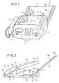
- Fig. 1 is a perspective view of a facsimile machine 1.
- the paper-feeding apparatus of the invention is applied to a facsimile machine
- the relevant paper feeding apparatus may be applied to any paper feeding apparatus for feeding recording paper as well as original paper used in information processing apparatus and communication apparatus or the like.
- Fig. 1 provided on the upper portion of the front face of the facsimile machine 1 optimum to access thereto for the user is an operation panel 2 to which a man-machine interface function is integrated. Disposed on the operation panel 2 is a display 3 on which the facsimile machine 1 presents the user with information as well as necessary guidance and operation keys 4 with which the user inputs instructions and dial numbers into the facsimile machine 1.
- the operation panel 2 is adapted to be opened and closed so as to allow the user to correct paper feed failure when an original or paper has jammed or a double feed or the like has occurred, or to clean the reading section easily.
- a handset 5 is equipped with a transmitter and a receiver for communicating through the telephone to be used to communicate by means of voices using the facsimile machine 1.
- an original hopper 6 Disposed behind the operation panel 2 is an original hopper 6 on which the original to be read for transmitting or duplicating is placed.
- the original hopper 6 is provided with a pair of original guides 7a, 7b for regulating the position of the original to prevent the original from skewing.
- one original guide 7a is disposed fixedly on the original hopper 6.
- Another original guide 7b is disposed so as to be movable in the guide slide directions B1, B2, which are second directions orthogonal to the paper feed direction A, which is a first direction in which the original is fed within the original loading plane 6a of the original hopper 6.
- regulation of the position of the original is made by sliding the another original guide 7b in the directions B1, B2 toward or away from the one original guide 7a; that is, in such a way, so-called one-side positioning.
- the position of the original may be regulated by means of moving both original guides 7a, 7b toward or away from each other in the direction of guide slide directions B1, B2 with reference to the center of the width in the guide slide directions B1, B2 on the original hopper 6.
- the original hopper 6 is also adapted to be opened and closed so as to allow to correct paper feed failure when a recording paper fed from the portion below the original hopper has jammed due to a double-feed or a skew as well as to easily carry out maintenance service on the printing section such as ink replacement.
- a recording paper hopper 8 for loading recording paper used to print out the received image and the read-out image.
- the recording paper hopper 8 is the loading table in the invention.
- the recording paper hopper 8 is provided with a pair of recording paper guides 9a, 9b for regulating the position of the recording paper to prevent the recording paper from skewing.
- the one recording paper guide 9a is disposed fixedly on the recording paper hopper 8.
- the other recording paper guide 9b is disposed so as to be movable in the guide slide directions B1, B2, that intersect the paper feed direction A at right angles, which is a first direction in which the recording paper is fed within the recording paper loading plane 8a of the recording paper hopper 8.
- regulation of the position of the recording paper may be made by sliding the both recording paper guides 9a, 9b toward or away from each other in the direction of guide slide directions B1, B2 with reference to the center of the width in the guide slide directions B1, B2 on the recording paper hopper 8.
- the original to be read is placed on the original hopper 6 and regulated the position at both sides thereof by the respective original guides 7a, 7b to prevent the original from skewing.
- the loaded originals are separated one by one at an original separating section 10 comprised of a roller 10a and a stop rubber 10b, and each original goes through between a contact sensor 11 and a platen roller 12.
- the contact sensor 11 reads out the image, and the original after being read is discharged to the outside of the machine by the original discharge roller 13.
- recording paper are loaded on the recording paper hopper 8.
- the recording paper is regulated the position at both sides thereof by the recording paper guides 9a, 9b.
- recording paper is placed on the hopper, in order to detect the size of the recording paper, a plurality of sensors are provided on the recording paper hopper 8.
- Each recording paper loaded on the recording paper hopper 8 is separated one by one by a recording paper separating section 14 comprised of a separator catch 14a for holding the recording paper at both sides thereof and a semilunar roller 14b, and is transported by a paper feed roller 15. Printing is made on the transported paper by a printing section 16 and is discharged outside of the machine from the recording paper discharge roller 17.
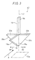
- Fig. 3 is a perspective view of an actuator 40 provided to the aforementioned paper sensor.
- the arrow A indicates the paper feed direction; whereas, the arrows B1, B2 indicate the moving directions of the guide.
- the word "paper sensor” means commonly both of the original sensor for detecting the status of an original and the recording paper sensor for detecting the recording paper, and the basic structure thereof is identical without depending on the case for the original or the recording paper. Therefore, in the following descriptions, a paper hopper 22 shown in Fig. 3, Fig. 4, Fig. 5A, Fig. 5B and Fig. 6A to Fig.
- a loading plane 22a means commonly the original loading plane 6a and the recording paper loading plane 8a.
- paper 24 means commonly both of the original and the recording paper.
- the actuator has a shaft 18 and, around the same, three fins 19, 20a, 20b are formed at the one end 18a of the shaft 18 adjacent to the loading plane 22a in the longitudinal direction.
- the fin disposed along to the paper feed direction is a paper detection fin 19; whereas, two fins disposed symmetrically extending toward the opposite directions from the shaft 18 in the directions of guide slide directions B1, B2 are paper guide retracting fins 20a, 20b that are the sliding portions.
- the paper detection fin 19 is used for detecting paper
- the paper guide retracting fins 20a, 20b are used for retracting the actuator 40 when the paper guide goes through between the actuator and the loading table.
- the respective fins 19, 20a, 20b are formed so that the distance between the respective sliding faces 19a, 26a, 26b and axis L1 of the shaft 18 is enlarged in the direction from the end 18a of the shaft 18 in the longitudinal direction toward the another end 18b of the shaft 18 in the longitudinal direction accordingly.
- the respective fins 19, 20a, 20b have a taper respectively.
- the configuration of the fins it is not limited to the configuration of the mode of the embodiment; it may be round-shaped or oval-shaped. That is to say, when the fin 19 and the paper 24 or the fins 20a, 20b and the paper guide 21 make sliding contact with each other, any configuration of the fins may be acceptable provided that it facilitates retraction of the actuator 40 by moving the fins 19, 20a, 20b in the direction separating away from the paper hopper along the normal of the loading plane 22a on the paper hopper 22 by an external force given by the paper 24 or the paper guide 21.
- the actuator 40 is disposed so as to be movable in the direction toward or away from the paper hopper along the slop line on the paper hopper 22 smoothly.
- the actuator 40 moves in the direction separating away from the loading table.
- the shaft 18 of the actuator 40 is the portion that is inserted into the inside of the facsimile machine 1.
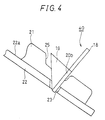
- Fig. 4 is a diagram illustrating a relationship between the actuator 40 and the paper guide 21.
- the paper hopper 22 as a paper loading table is formed with a paper hopper notch 23 at a portion where it comes in contact with the actuator 40.
- the hopper notch 23 is the concave portion of the invention. Since it is made possible for the actuator 40 to be positioned closer to the paper hopper 22 as much as the actuator 40 is inserted into the paper hopper notch 23, it is made possible to make the stroke of the paper sensor be longer as well as to detect the paper correctly even when, for example, only a sheet of paper is remaining on the paper hopper 22.
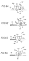
- FIG. 5A and Fig. 5B are diagrams illustrating the paper hopper 22 viewed from the side thereof. To simplify the diagram, the paper guide 21 is omitted.
- the paper 24 is fed in the direction of the arrow A. After the paper 24 has come in contact with the actuator 40, as the paper 24 moves in the paper feed direction, shearing forces F1, F2 are generated in the opposite directions to each other along the sliding face 19a of the paper detection fin 19 at the portion where the paper 24 and the paper detection fin 19 come in contact with each other.
- a component F1N that is parallel to the direction of the normal of the paper loading plane 22a acts on the paper 24 as a force to make the paper 24 closer to the paper hopper 22.
- a component F2N which is opposite direction to the component F1N acts as a force that make the paper detection fin 19 separate away from the paper hopper 22.
- the actuator 40 moves along the axis L1 of the shaft 18 and is adapted to be engaged with and disengaged from the facsimile machine 1.
- the shaft 18 moves in the direction separating away from the paper hopper 22 along the normal to the paper loading plane 22a.
- the shaft 18 allows the beam from a photosensor 30 provided to the facsimile machine 1 to pass through or cut it off.
- the photosensor 30 detects the shaft 18. As a result, it is detected whether paper resides or not.
- the paper guide retracting fins 20a, 20b also have the sloped sliding faces 26a, 26b respectively.
- a paper guide notch 25 as shown in the figures to be referred hereinafter is formed at a point where the same comes in contact with the guide retracting fins 20a 20b.
- the height of the paper guide 21 at the notch 25 is formed to be lower than the other portions of the paper guide 21.
- Fig. 6A illustrates a status in which the lower portion of the actuator 40 is inserted into a paper hopper notch 23 and is resting therein.
- Fig. 6B illustrates a status in which the paper guide 21 has come in contact with the paper guide retracting fin 20, in case where the paper 24 is loaded and in order to regulate the position of the paper 24 in accordance with the size of the paper, the paper guide 21 is moved in the direction of the guide slide direction B1 to make the paper guide to be closer to the paper 24.
Abstract
Description
Claims (8)
- A paper feeding apparatus comprising:a loading table (6, 8, 22) having a loading plane (6a, 8a, 22a) on which paper (24) is placed,a paper guide (7, 9, 21) disposed to be movable in a second direction (B1, B2) orthogonal to a first direction (A) in which the paper (24) is fed so as to come in contact with a side face of the paper (24) at the second direction (B1, B2) side to regulate a position of the paper (24), anda sensor (30) provided with an actuator (40) disposed to be movable in a direction of a normal to the loading plane (6a, 8a, 22a), for detecting status of the paper (24) on the loading table (6, 8, 22) based on a position of the actuator (40) in the direction of the normal to the loading plane (6a, 8a, 22a),wherein the actuator (40) is retracted in the direction separating away from the loading table (6, 8, 22) along the direction of the normal to the loading table (6, 8, 22) by a contact of the actuator (40) with the paper guide (7, 9, 21) movable in the second direction (B1, B2).
- The paper feeding apparatus of claim 1, wherein the paper guide (7, 9, 21) is movable in accordance with the size of the paper between the actuator (40) separated away from the loading table (6, 8, 22) and the loading table (6, 8, 22).
- The paper feeding apparatus of claim 1, wherein the actuator (40) has a shaft (18) extending along an axis (L1) parallel to the normal to the loading plane (6a, 8a, 22a) and a sliding portion (20a, 20b) formed on one end (18a) of the shaft (18) in a longitudinal direction close to the loading plane (6a, 8a, 22a) and extending in the second direction (B1, B2), for sliding on the paper guide (7, 9, 21), the sliding portion (20a, 20b) is formed so that a distance between the sliding face (26a, 26b) and the axis (L1) of the shaft (18) is enlarged from the one end (18a) of the shaft (18) in the longitudinal direction toward the another end (18b) in the longitudinal direction.
- The paper feeding apparatus of claim 2, wherein the actuator (40) has a shaft (18) extending along an axis (L1) parallel to the normal to the loading plane (6a, 8a, 22a) and a sliding portion (20a, 20b) formed on one end (18a) of the shaft (18) in a longitudinal direction close to the loading plane (6a, 8a, 22a) and extending in the second direction (B1, B2), for sliding on the paper guide (7, 9, 21), the sliding portion (20a, 20b) is formed so that a distance between the sliding face (26a, 26b) and the axis (L1) of the shaft (18) is enlarged from the one end (18a) of the shaft (18) in the longitudinal direction toward the another end (18b) in the longitudinal direction.
- The paper feeding apparatus of claim 3, wherein the sliding section (20a, 20b) is disposed at both sides of the shaft (18) in the second direction (B1, B2).
- The paper feeding apparatus of claim 4, wherein the sliding section (20a, 20b) is disposed at both sides of the shaft (18) in the second direction (B1, B2).
- The paper feeding apparatus of claim 1, wherein the paper guide (7, 9, 21) has a notch (25) which is formed at a portion where the paper guide (7, 9, 21) comes in contact with the actuator (40).
- The paper feeding apparatus of claim 1, wherein the loading table (6, 8, 22) is provided with a concave portion (23) to which the actuator (40) fits.
Applications Claiming Priority (2)
| Application Number | Priority Date | Filing Date | Title |
|---|---|---|---|
| JP2000295200 | 2000-09-27 | ||
| JP2000295200A JP2002104662A (en) | 2000-09-27 | 2000-09-27 | Paper feed device |
Publications (3)
| Publication Number | Publication Date |
|---|---|
| EP1193198A2 true EP1193198A2 (en) | 2002-04-03 |
| EP1193198A3 EP1193198A3 (en) | 2003-05-07 |
| EP1193198B1 EP1193198B1 (en) | 2005-07-20 |
Family
ID=18777662
Family Applications (1)
| Application Number | Title | Priority Date | Filing Date |
|---|---|---|---|
| EP01123070A Expired - Lifetime EP1193198B1 (en) | 2000-09-27 | 2001-09-26 | Paper feeding apparatus |
Country Status (5)
| Country | Link |
|---|---|
| US (1) | US6651977B2 (en) |
| EP (1) | EP1193198B1 (en) |
| JP (1) | JP2002104662A (en) |
| DE (1) | DE60112013T2 (en) |
| HK (1) | HK1045491B (en) |
Families Citing this family (10)
| Publication number | Priority date | Publication date | Assignee | Title |
|---|---|---|---|---|
| US6824133B2 (en) * | 2002-10-17 | 2004-11-30 | Hewlett-Packard Development Company, L.P. | Stack monitoring method and system |
| US6986509B2 (en) * | 2004-02-05 | 2006-01-17 | Hewlett-Packard Development Company, Lp. | Media stack tray status mechanism |
| US7198265B2 (en) * | 2004-08-31 | 2007-04-03 | Lexmark International, Inc. | Imaging apparatus including a movable media sensor |
| US20080303204A1 (en) * | 2007-06-05 | 2008-12-11 | Yueh-Shing Lee | Paper feeding device |
| JP5270883B2 (en) * | 2007-08-31 | 2013-08-21 | 京セラドキュメントソリューションズ株式会社 | Paper feeder |
| US7871027B2 (en) | 2008-02-13 | 2011-01-18 | Techko, Inc. | Auto feed shredder apparatus and methods |
| JP5102136B2 (en) * | 2008-07-28 | 2012-12-19 | 京セラドキュメントソリューションズ株式会社 | Paper conveying apparatus and image forming apparatus |
| JP2016098116A (en) * | 2014-11-26 | 2016-05-30 | キヤノン株式会社 | Sheet detection device and sheet feeding device including the same and image formation device |
| US9975716B2 (en) | 2014-11-19 | 2018-05-22 | Canon Kabushiki Kaisha | Sheet detecting device, sheet feeding unit including the same and image forming apparatus |
| JP2022101142A (en) * | 2020-12-24 | 2022-07-06 | キヤノン株式会社 | Recording device |
Citations (5)
| Publication number | Priority date | Publication date | Assignee | Title |
|---|---|---|---|---|
| US4449705A (en) * | 1980-02-18 | 1984-05-22 | Tokyo Shibaura Denki Kabushiki Kaisha | Paper feed device |
| JPS61238633A (en) * | 1985-04-12 | 1986-10-23 | Hitachi Ltd | Paper detector |
| US5028041A (en) * | 1984-10-26 | 1991-07-02 | Canon Kabushiki Kaisha | Image forming apparatus with sheet feeder |
| JPH0967044A (en) * | 1995-08-30 | 1997-03-11 | Canon Inc | Sheet stack presence state detecting device and image processing device |
| US5743522A (en) * | 1996-11-14 | 1998-04-28 | Xerox Corporation | Document or copy sheet tray sheet set sensor actuator |
Family Cites Families (12)
| Publication number | Priority date | Publication date | Assignee | Title |
|---|---|---|---|---|
| JPS5964450A (en) | 1982-10-05 | 1984-04-12 | Canon Inc | Device for sensing of slant running sheet |
| JPS61229755A (en) | 1985-04-05 | 1986-10-14 | Ricoh Co Ltd | Paper feeding device |
| JPS61263552A (en) | 1985-05-15 | 1986-11-21 | Tokyo Electric Co Ltd | Oblique advance detector |
| JPS62285829A (en) | 1986-06-02 | 1987-12-11 | Canon Inc | Automatic original feed device provided with digitizer device |
| JP2575700B2 (en) | 1987-04-30 | 1997-01-29 | キヤノン株式会社 | Automatic document feeder |
| JPH0558012A (en) | 1991-07-04 | 1993-03-09 | Canon Inc | Image recording device |
| US5552859A (en) * | 1994-02-08 | 1996-09-03 | Canon Kabushiki Kaisha | Sheet supplying apparatus with means for rocking sheet stacking plate |
| JPH08239130A (en) * | 1995-03-06 | 1996-09-17 | Mita Ind Co Ltd | Image forming device |
| JP3365214B2 (en) | 1996-09-09 | 2003-01-08 | ミノルタ株式会社 | Document feeder |
| KR100208140B1 (en) * | 1996-09-25 | 1999-07-15 | 윤종용 | Auto paper feeding device and method thereof in ink-jet printer |
| JPH11322131A (en) | 1998-05-14 | 1999-11-24 | Minolta Co Ltd | Manual paper feeder |
| US6247695B1 (en) * | 1998-12-23 | 2001-06-19 | Xerox Corporation | Multiple zone stack height sensor for high capacity feeder |
-
2000
- 2000-09-27 JP JP2000295200A patent/JP2002104662A/en active Pending
-
2001
- 2001-09-26 DE DE60112013T patent/DE60112013T2/en not_active Expired - Fee Related
- 2001-09-26 EP EP01123070A patent/EP1193198B1/en not_active Expired - Lifetime
- 2001-09-27 US US09/963,468 patent/US6651977B2/en not_active Expired - Fee Related
-
2002
- 2002-09-25 HK HK02107007.4A patent/HK1045491B/en not_active IP Right Cessation
Patent Citations (5)
| Publication number | Priority date | Publication date | Assignee | Title |
|---|---|---|---|---|
| US4449705A (en) * | 1980-02-18 | 1984-05-22 | Tokyo Shibaura Denki Kabushiki Kaisha | Paper feed device |
| US5028041A (en) * | 1984-10-26 | 1991-07-02 | Canon Kabushiki Kaisha | Image forming apparatus with sheet feeder |
| JPS61238633A (en) * | 1985-04-12 | 1986-10-23 | Hitachi Ltd | Paper detector |
| JPH0967044A (en) * | 1995-08-30 | 1997-03-11 | Canon Inc | Sheet stack presence state detecting device and image processing device |
| US5743522A (en) * | 1996-11-14 | 1998-04-28 | Xerox Corporation | Document or copy sheet tray sheet set sensor actuator |
Non-Patent Citations (2)
| Title |
|---|
| PATENT ABSTRACTS OF JAPAN vol. 011, no. 086 (M-572), 17 March 1987 (1987-03-17) & JP 61 238633 A (HITACHI LTD), 23 October 1986 (1986-10-23) * |
| PATENT ABSTRACTS OF JAPAN vol. 1997, no. 07, 31 July 1997 (1997-07-31) -& JP 09 067044 A (CANON INC), 11 March 1997 (1997-03-11) * |
Also Published As
| Publication number | Publication date |
|---|---|
| JP2002104662A (en) | 2002-04-10 |
| EP1193198B1 (en) | 2005-07-20 |
| US20020036378A1 (en) | 2002-03-28 |
| HK1045491A1 (en) | 2002-11-29 |
| HK1045491B (en) | 2005-12-02 |
| DE60112013T2 (en) | 2006-04-20 |
| US6651977B2 (en) | 2003-11-25 |
| DE60112013D1 (en) | 2005-08-25 |
| EP1193198A3 (en) | 2003-05-07 |
Similar Documents
| Publication | Publication Date | Title |
|---|---|---|
| US8292176B2 (en) | Card processing device | |
| EP3528483B1 (en) | Medium feeding device and image reading apparatus | |
| EP1193198B1 (en) | Paper feeding apparatus | |
| JP6812766B2 (en) | Image forming apparatus, image forming system, and control program of image forming system | |
| EP1457445A2 (en) | Sheet feeder in image reading apparatus | |
| JP2006333282A (en) | Automatic document feeder, and image forming apparatus including the same | |
| US6678071B1 (en) | Image-reading apparatus | |
| EP1652370B1 (en) | Scanning irregularly shaped documents | |
| JP4650179B2 (en) | Automatic paper feeding device, image reading device, and image forming device | |
| JP4815964B2 (en) | Image reading device | |
| US8020862B2 (en) | Sheet conveyance device, image forming apparatus and image reading apparatus | |
| EP2019062B1 (en) | Recording media storage device, recording media processing device corresponding thereto, and storage condition detection method | |
| JP4477652B2 (en) | Automatic document feeder, image reading apparatus including the same, and image forming apparatus | |
| JP2007137035A (en) | Control method of print medium processor and print medium processor | |
| JP4113245B2 (en) | Automatic document feeder | |
| JP4675817B2 (en) | Automatic paper conveyance device, image reading device, and image forming device | |
| JP5009188B2 (en) | Paper aligning device, paper stacking device, and image forming device | |
| JP2009234678A (en) | Sheet carrying device, image reading device, and image forming device | |
| JP4549963B2 (en) | Automatic document feeder | |
| US6254087B1 (en) | Sheet transport device and sheet transport method | |
| JP7446839B2 (en) | Sheet feeding device, sheet reading device equipped with a sheet feeding device, image forming device equipped with a sheet reading device | |
| JP4563221B2 (en) | Automatic document feeder, image reading apparatus, and image forming apparatus | |
| JP5068721B2 (en) | Automatic document feeder and image forming apparatus | |
| US20020050678A1 (en) | Original sheet reading apparatus | |
| JP7271883B2 (en) | Sheet conveying device and image reading device |
Legal Events
| Date | Code | Title | Description |
|---|---|---|---|
| PUAI | Public reference made under article 153(3) epc to a published international application that has entered the european phase |
Free format text: ORIGINAL CODE: 0009012 |
|
| AK | Designated contracting states |
Kind code of ref document: A2 Designated state(s): AT BE CH CY DE DK ES FI FR GB GR IE IT LI LU MC NL PT SE TR |
|
| AX | Request for extension of the european patent |
Free format text: AL;LT;LV;MK;RO;SI |
|
| PUAL | Search report despatched |
Free format text: ORIGINAL CODE: 0009013 |
|
| AK | Designated contracting states |
Designated state(s): AT BE CH CY DE DK ES FI FR GB GR IE IT LI LU MC NL PT SE TR |
|
| AX | Request for extension of the european patent |
Extension state: AL LT LV MK RO SI |
|
| RIC1 | Information provided on ipc code assigned before grant |
Ipc: 7B 65H 7/02 B Ipc: 7B 65H 31/34 B Ipc: 7B 65H 1/04 B Ipc: 7B 65H 7/04 A Ipc: 7B 65H 9/10 B Ipc: 7B 65H 7/14 B Ipc: 7B 65H 9/04 B |
|
| 17P | Request for examination filed |
Effective date: 20030902 |
|
| AKX | Designation fees paid |
Designated state(s): DE GB |
|
| 17Q | First examination report despatched |
Effective date: 20040210 |
|
| GRAP | Despatch of communication of intention to grant a patent |
Free format text: ORIGINAL CODE: EPIDOSNIGR1 |
|
| GRAS | Grant fee paid |
Free format text: ORIGINAL CODE: EPIDOSNIGR3 |
|
| GRAA | (expected) grant |
Free format text: ORIGINAL CODE: 0009210 |
|
| AK | Designated contracting states |
Kind code of ref document: B1 Designated state(s): DE GB |
|
| REG | Reference to a national code |
Ref country code: GB Ref legal event code: FG4D |
|
| REF | Corresponds to: |
Ref document number: 60112013 Country of ref document: DE Date of ref document: 20050825 Kind code of ref document: P |
|
| REG | Reference to a national code |
Ref country code: HK Ref legal event code: GR Ref document number: 1045491 Country of ref document: HK |
|
| PLBE | No opposition filed within time limit |
Free format text: ORIGINAL CODE: 0009261 |
|
| STAA | Information on the status of an ep patent application or granted ep patent |
Free format text: STATUS: NO OPPOSITION FILED WITHIN TIME LIMIT |
|
| 26N | No opposition filed |
Effective date: 20060421 |
|
| PGFP | Annual fee paid to national office [announced via postgrant information from national office to epo] |
Ref country code: GB Payment date: 20060922 Year of fee payment: 6 |
|
| PGFP | Annual fee paid to national office [announced via postgrant information from national office to epo] |
Ref country code: DE Payment date: 20060927 Year of fee payment: 6 |
|
| GBPC | Gb: european patent ceased through non-payment of renewal fee |
Effective date: 20070926 |
|
| PG25 | Lapsed in a contracting state [announced via postgrant information from national office to epo] |
Ref country code: DE Free format text: LAPSE BECAUSE OF NON-PAYMENT OF DUE FEES Effective date: 20080401 |
|
| PG25 | Lapsed in a contracting state [announced via postgrant information from national office to epo] |
Ref country code: GB Free format text: LAPSE BECAUSE OF NON-PAYMENT OF DUE FEES Effective date: 20070926 |