EP1192879B1 - Seat for a reclining office chair - Google Patents
Seat for a reclining office chair Download PDFInfo
- Publication number
- EP1192879B1 EP1192879B1 EP01308204A EP01308204A EP1192879B1 EP 1192879 B1 EP1192879 B1 EP 1192879B1 EP 01308204 A EP01308204 A EP 01308204A EP 01308204 A EP01308204 A EP 01308204A EP 1192879 B1 EP1192879 B1 EP 1192879B1
- Authority
- EP
- European Patent Office
- Prior art keywords
- seat
- seat portion
- panel
- pattern
- weakeners
- Prior art date
- Legal status (The legal status is an assumption and is not a legal conclusion. Google has not performed a legal analysis and makes no representation as to the accuracy of the status listed.)
- Expired - Lifetime
Links
Images


Classifications
-
- A—HUMAN NECESSITIES
- A47—FURNITURE; DOMESTIC ARTICLES OR APPLIANCES; COFFEE MILLS; SPICE MILLS; SUCTION CLEANERS IN GENERAL
- A47C—CHAIRS; SOFAS; BEDS
- A47C1/00—Chairs adapted for special purposes
- A47C1/02—Reclining or easy chairs
- A47C1/022—Reclining or easy chairs having independently-adjustable supporting parts
- A47C1/023—Reclining or easy chairs having independently-adjustable supporting parts the parts being horizontally-adjustable seats ; Expandable seats or the like, e.g. seats with horizontally adjustable parts
-
- A—HUMAN NECESSITIES
- A47—FURNITURE; DOMESTIC ARTICLES OR APPLIANCES; COFFEE MILLS; SPICE MILLS; SUCTION CLEANERS IN GENERAL
- A47C—CHAIRS; SOFAS; BEDS
- A47C1/00—Chairs adapted for special purposes
- A47C1/02—Reclining or easy chairs
- A47C1/022—Reclining or easy chairs having independently-adjustable supporting parts
- A47C1/03—Reclining or easy chairs having independently-adjustable supporting parts the parts being arm-rests
- A47C1/0307—Reclining or easy chairs having independently-adjustable supporting parts the parts being arm-rests adjustable rectilinearly in horizontal direction
-
- A—HUMAN NECESSITIES
- A47—FURNITURE; DOMESTIC ARTICLES OR APPLIANCES; COFFEE MILLS; SPICE MILLS; SUCTION CLEANERS IN GENERAL
- A47C—CHAIRS; SOFAS; BEDS
- A47C1/00—Chairs adapted for special purposes
- A47C1/02—Reclining or easy chairs
- A47C1/031—Reclining or easy chairs having coupled concurrently adjustable supporting parts
- A47C1/032—Reclining or easy chairs having coupled concurrently adjustable supporting parts the parts being movably-coupled seat and back-rest
- A47C1/03205—Reclining or easy chairs having coupled concurrently adjustable supporting parts the parts being movably-coupled seat and back-rest having adjustable and lockable inclination
-
- A—HUMAN NECESSITIES
- A47—FURNITURE; DOMESTIC ARTICLES OR APPLIANCES; COFFEE MILLS; SPICE MILLS; SUCTION CLEANERS IN GENERAL
- A47C—CHAIRS; SOFAS; BEDS
- A47C1/00—Chairs adapted for special purposes
- A47C1/02—Reclining or easy chairs
- A47C1/031—Reclining or easy chairs having coupled concurrently adjustable supporting parts
- A47C1/032—Reclining or easy chairs having coupled concurrently adjustable supporting parts the parts being movably-coupled seat and back-rest
- A47C1/03255—Reclining or easy chairs having coupled concurrently adjustable supporting parts the parts being movably-coupled seat and back-rest with a central column, e.g. rocking office chairs
-
- A—HUMAN NECESSITIES
- A47—FURNITURE; DOMESTIC ARTICLES OR APPLIANCES; COFFEE MILLS; SPICE MILLS; SUCTION CLEANERS IN GENERAL
- A47C—CHAIRS; SOFAS; BEDS
- A47C31/00—Details or accessories for chairs, beds, or the like, not provided for in other groups of this subclass, e.g. upholstery fasteners, mattress protectors, stretching devices for mattress nets
- A47C31/12—Means, e.g. measuring means for adapting chairs, beds or mattresses to the shape or weight of persons
- A47C31/126—Means, e.g. measuring means for adapting chairs, beds or mattresses to the shape or weight of persons for chairs
-
- A—HUMAN NECESSITIES
- A47—FURNITURE; DOMESTIC ARTICLES OR APPLIANCES; COFFEE MILLS; SPICE MILLS; SUCTION CLEANERS IN GENERAL
- A47C—CHAIRS; SOFAS; BEDS
- A47C7/00—Parts, details, or accessories of chairs or stools
- A47C7/002—Chair or stool bases
- A47C7/004—Chair or stool bases for chairs or stools with central column, e.g. office chairs
-
- A—HUMAN NECESSITIES
- A47—FURNITURE; DOMESTIC ARTICLES OR APPLIANCES; COFFEE MILLS; SPICE MILLS; SUCTION CLEANERS IN GENERAL
- A47C—CHAIRS; SOFAS; BEDS
- A47C7/00—Parts, details, or accessories of chairs or stools
- A47C7/002—Chair or stool bases
- A47C7/006—Chair or stool bases with castors
-
- A—HUMAN NECESSITIES
- A47—FURNITURE; DOMESTIC ARTICLES OR APPLIANCES; COFFEE MILLS; SPICE MILLS; SUCTION CLEANERS IN GENERAL
- A47C—CHAIRS; SOFAS; BEDS
- A47C7/00—Parts, details, or accessories of chairs or stools
- A47C7/02—Seat parts
- A47C7/029—Seat parts of non-adjustable shape adapted to a user contour or ergonomic seating positions
-
- A—HUMAN NECESSITIES
- A47—FURNITURE; DOMESTIC ARTICLES OR APPLIANCES; COFFEE MILLS; SPICE MILLS; SUCTION CLEANERS IN GENERAL
- A47C—CHAIRS; SOFAS; BEDS
- A47C7/00—Parts, details, or accessories of chairs or stools
- A47C7/02—Seat parts
- A47C7/22—Straps or the like for direct user support or for carrying upholstery
-
- A—HUMAN NECESSITIES
- A47—FURNITURE; DOMESTIC ARTICLES OR APPLIANCES; COFFEE MILLS; SPICE MILLS; SUCTION CLEANERS IN GENERAL
- A47C—CHAIRS; SOFAS; BEDS
- A47C7/00—Parts, details, or accessories of chairs or stools
- A47C7/02—Seat parts
- A47C7/28—Seat parts with tensioned springs, e.g. of flat type
- A47C7/282—Seat parts with tensioned springs, e.g. of flat type with mesh-like supports, e.g. elastomeric membranes
-
- A—HUMAN NECESSITIES
- A47—FURNITURE; DOMESTIC ARTICLES OR APPLIANCES; COFFEE MILLS; SPICE MILLS; SUCTION CLEANERS IN GENERAL
- A47C—CHAIRS; SOFAS; BEDS
- A47C7/00—Parts, details, or accessories of chairs or stools
- A47C7/36—Support for the head or the back
- A47C7/40—Support for the head or the back for the back
- A47C7/46—Support for the head or the back for the back with special, e.g. adjustable, lumbar region support profile; "Ackerblom" profile chairs
- A47C7/462—Support for the head or the back for the back with special, e.g. adjustable, lumbar region support profile; "Ackerblom" profile chairs adjustable by mechanical means
Definitions
- the present invention relates to a flexible or foldable panel for a seat such as a chair or a stool.
- a seat such as a chair or a stool.
- the invention relates to a flexible panel for a reclinable office chair.
- a seat depth adjustment mechanism is also described, While the invention is described in terms of commercial office chairs, the invention may have application to any other type of seating such as public seating for theatres, aircraft or domestic seating.
- US Patents Nos. 5,050,931 and US 4,498,702 In office chairs, it is desirable to have seat portions in which the forward portion is deflectable under the weight of the occupant See for example US Patents Nos. 5,050,931 and US 4,498,702.
- US Patent No. 5,050,931 has a generally flexible seat portion but a relatively complex spring mechanism is required in order to upwardly bias the forward portion and prevent it from unduly sagging under the occupant's weight
- the arrangement shown in US Patent 4,498,702 is a cumbersome arrangement in which a separate forward portion of the seat portion is connected to a rearward portion of the seat portion by leaf springs.
- the prior art suffers from the disadvantage that in order for the seat portion to have sufficient strength, complex spring mechanisms are required to prevent the forward portion from unduly sagging under the weight of the occupant.
- a seat portion for a seat according to claim 1 In accordance with a first aspect of the present invention there is provided a seat portion for a seat according to claim 1.
- the panel is of a unitary construction which is weakened in specific locations enabling the zones to form pockets which accommodate the ischial protuberosities of an occupant sitting in the seat.
- a plurality of weakeners are provided to provide the zones with increased "give" in response to an occupant sitting in the seat.
- the weakeners may be in the form of apertures.
- the seat panel may be perforated.
- a slotted pattern is the most preferred construction.
- An alternative construction is to provide weakeners, each of which is in the form of a reduction in thickness in the specific location where it is desired to increase flexibility.
- the seat portion may also include a forward portion integrally formed with the back portion to form a unitary shell to support the occupant.
- the seat panel might be provided with an overall pattern of weakeners to enhance flexibility.
- the zones may have an increased concentration of weakeners compared to the remainder of the seat panel.
- a preferred overall pattern is a pattern of weakeners arranged as a series of spaced transversely extending sinuous lines.
- the pattern of transversely extending sinuous lines is interrupted by the two zones.
- the zones may be of any shape such as circular, square, although a rectangular shape is preferred which allows some flexibility as to the particular location of the seated occupant relative to the seat panel and also allows for the fact that chair occupants come in an different shapes and sizes.
- the zones also include a pattern of weakeners arranged in spaced longitudinally extending sinuous lines.
- the weakeners in the zones are slots.
- the longitudinally extending lines within the zones may be more closely spaced than the transversely extending lines in the remainder of the seat panel.
- the frequency of the repeating wave of the longitudinally extending lines in the zones is greater than the frequency of the transverse sinuous lines in the remainder of the seat panel.
- the seat panel is preferably an integral one piece panel incorporating the rear portion and the forward portion. Additionally, the seat panel could be integral with the back panel incorporating an integral hinge to allow flexibility between the back panel and the scat panel.
- the seat panel is preferably of moulded plastics construction which is moulded in a specific shape to enhance user comfort. In particular, the rear of the seat panel may be dished. Furthermore, at approximately one third of the length of the seat panel along the longitudinal centreline, there may be provided a transverse plateau portion which is generally flat. Forwardly of the transverse plateau portion, preferably the seat portion dips downwardly. Additionally, the corners may also dip downwardly.
- the panel essentially comprises a sheet.
- the sheet may incorporate stiffening webs on the underside thereof extending in either the transverse or longitudinal direction.
- the stiffening webs extending in the transverse direction follow the pattern of spaced transversely extending sinuous lines.
- the transverse webs may be disposed in between the lines of weakeners.
- a seat panel for a seat comprising a rear portion to support the occupant, the rear portion having a longitudinal centerline and incorporating two zones either side of the longitudinal centerline, there being surrounding portions surrounding the zones, wherein the panel is of a construction which provides enhanced flexibility in each of the zones compared to the surrounding portions and wherein a substantial portion of the panel, apart from the zones is provided with a pattern of weakeners arranged in a series of spaced sinuous lines, interrupted by the zones.
- the flexible panel described in the abovementioned aspect may incorporate any of the preferred features described in accordance with the first aspect of the invention as set out above.
- a seat construction for supporting a seat occupant, the seat construction including: a seat portion which is foldable about a transverse fold under the weight of the occupant; a seat depth adjustment mechanism to adjust the position of the seat portion in and out over a range of positions between an extended position and a retracted position, wherein the seat portion incorporates a resistance to folding which increases as the seat position is adjusted towards the extended position.
- the seat depth adjustment mechanism may include a seat guide, the seat portion being moveable relative to the seat guide with the seat portion being transversely foldable relative to a fixed portion of the seat guide such that the transverse fold shifts by an amount corresponding to the depth adjustment of the seat. Accordingly, the transverse fold may lie anywhere within a predetermined transition zone on the seat portion.
- the construction of the seat portion may vary over the transition zone in order to provide the corresponding adjustment of the resistance to folding.
- the thickness of the seat portion may increase over the transition zone in the direction towards the rear of the seat portion.
- the transition and thickness may be a stepped increase or gradual ie tapered seat portion.
- the seat portion incorporates longitudinally extending stiffening webs.
- the longitudinal webs are provided on the underside of the seat portion.
- the longitudinally extending webs may increase in girth over the transition zone in the direction towards the rear of the seat.
- the webs may increase in height or alternatively increase in thickness.
- the longitudinally extending webs begin at nil thickness at the beginning of the transition zone and gradually increase m height in the rearward direction, over the transition zone, the longitudinal webs being maintained of a uniform height rearwardly of the transition zone.
- the seat portion is one piece.
- the seat portion is an integral moulded plastic panel construction.
- the seat depth adjustment mechanism may be selectively operable by the seat occupant.
- the position of the seat portion may be adjustable in increments so that the seat portion may adopt any one of a finite number of positions between the extended and the retracted position.
- the seat depth adjustment mechanism includes a lock having a locked configuration and an unlocked configuration with the seat depth adjustment mechanism being normally biased towards the locked configuration with an actuator provided to selectively move the lock to the unlocked configuration.
- the seat depth adjustment mechanism includes a seat carriage slidably supported on the seat guide.
- the seat carriage may incorporate the seat portion.
- the seat portion is a discrete member attached to the seat carriage.
- the seat portion is in the form of a flexible panel fixed to the seat carriage.
- the panel further includes a plurality of dependent spacers disposed forwardly of the seat carriage.
- the spacers bear against the seat guide when the occupant's weight is brought to bear on a forward part of the seat portion.
- the spacers are arranged in a longitudinally extending line and gaps may be provided between adjacent spacers such that when the sides or edges of the spacers on each side of the gaps engage, the maximum curvature of the transverse fold is defined.
- the gaps are in the form of invoked V-shaped gaps such that on maximum curvature of the transverse fold, the sides of each gap engage with each other to close the gap.
- the spacers comprise a series of blocks which extend longitudinally over the length of the transition zone.
- the blocks also reduce in height towards the front of the seat portion.
- the top of the blocks may define a taper.
- the seat carriage is slidably supported on two guides arranged on opposite sides of the seat construction. Accordingly, there may be two sets of spacers, each of which bear against a respective seat guide.
- the seat portion may comprise a flexible panel which is moulded into a three dimensional shape to enhance comfort for the occupant.
- the features of three dimensional shape described above in accordance with the first aspect of the invention may be applied to the aspect of the invention defined above.
- the seat panel may incorporate a pattern of weakeners to enhance the flexibility and the foldability of the seat panel as discussed in connection with the foregoing aspects of the invention.
- a seat construction for supporting a seat occupant including: a seat portion which is foldable about a transverse fold under the weight of the occupant; a seat depth adjustment mechanism to adjust the seat portion in and out over a range of positions between an extended position and a retracted position, the seat depth adjustment mechanism including a seat guide relative to which the seat portion is adjustably moveable, wherein the seat portion folds transversely about a fixed portion of me seat guide.
- a transition zone may be defined in the seat portion between the location of the transverse fold in the retracted position of the seat portion and the location of the transverse fold in to the extended position of the seat portion.
- the seat portion is a one piece plastics panel provided with a patterns of weakeners, the pattern extending for at least the width of the transition zone to enhance the transverse foldability of the seat panel over the transition zone.
- the pattern of weakeners may incorporate any of the features described above in accordance with the first aspect of the invention.
- the preferred form is a series of spaced lines of discontinuous slots, the lines extending sinuously in a transverse direction with the lines curving convex forwardly across the centreline of the seat portion.
- the seat portion may be carried by a seat carriage which is moveable relative to the seat guide.
- the seat portion may be in the form of a flexible panel which incorporates dependent spacers as described in connection with the preceding aspect of the invention.
- a flexible seat panel for supporting a seat occupant, the seat panel being foldable about a transverse fold under the weight of the occupant wherein the panel incorporates longitudinally extending stiffening webs which, for at least a portion of their length increase in girth in the rearward direction.
- the longitudinal webs may be variable in either width or height or a combination of both over said portion of their length.
- the webs taper in height in the rearward direction.
- the panel may be foldable about a transverse fold anywhere within a transition zone disposed in an intermediate location of the panel.
- the webs offer increased resistance to folding as the transverse fold is moved in the rearward direction over this transition zone.
- a seat depth adjustment mechanism including: a seat guide; and a seat carriage slidably supported on the seat guide, the seat carriage being slidable between a retracted position and an extended position, wherein the seat guide has a guide glide surface and the seat carriage has a carriage glide surface, the guide glide surface and the carriage glide surface being in sliding engagement with each other, wherein one of the glide surfaces is formed by a liner having integral resilient projections engaging the other of the glide surfaces.
- the liner is in the form of a plastic liner having integrally formed projections.
- the plastic liner may be moulded.
- the resilient projections may be of any shape.
- the resilient projections are in the form of archlets.
- the archlets are formed with ends which are contiguous with the remainder of the glide surface from which they project with the side edges of the archlets being spaced therefrom, thereby defining arch-shaped openings on each side.
- the archlets are arranged in a staggered pattern.
- the liner is incorporated into the seat guide.
- the liner may alternatively be incorporated into the carriage.
- each of the seat guides may incorporate a liner, the two liners being a mirror image of each other.
- Each of the plastic liners may be supported by a metal part of the guide.
- the glide surfaces with the projections may define two facing uptight glide surfaces engaging against upright glide surfaces on opposite sides of the carriage.
- each glide surface with the projections is maintained in spaced configuration from the associated metal part of the seat guide. This also provides a measure of resiliency for the glide surface with projections.
- the glide surface with projections is maintained in spaced configuration front the associated scat guide by a peripheral wall extending from the seat guide to the glide surface with projections. It will be appreciated that this arrangement with two facing glide surfaces with projections is advantageous since it centres a carriage between the two seat guides. The arrangement also takes up any slack between the carriage and the adjacent seat guides, thereby reducing the risk of jamming of the seat carriage between the seat guides.
- the liners may also include upper glide surfaces on which the carriage is supported. These upper glide surfaces may be provided with or without resilient projections.
- the liners are formed as integrally moulded plastic constructions including the upper glide surfaces and the upright glide surfaces, and being of L-shape in transverse section.
- the seat adjustment mechanism may be provided with a user operable lock in order to secure the seat carriage at a selected location between the retracted position and the extended position.
- the lock is biased towards the locked configuration.
- a seat depth adjustment mechanism including: a seat guide; and a scat carriage slidably supported on the seat guide, the seat carriage being slidable between a retracted position and an extended position, the seat guide including a supporting portion supporting a liner, the liner having a guide glide surface and the scat carriage having a carriage glide surface, the guide glide surface and the carriage glide surface being in sliding engagement with each other, wherein the guide glide surface includes integral resilient projections directed towards and engageable with the supporting portion, the remainder of the guide glide surface being spaced from the supporting portion.
- This invention may also be said broadly to consist in the parts, elements and features referred to or indicated in the specification of the application, individually or collectively, and any or all combinations of any two or more of said parts, elements or features, and where specific integers are mentioned herein which have known equivalents in the art to which this invention relates, such known equivalents are deemed to be incorporated herein as if individually set forth.
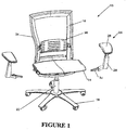
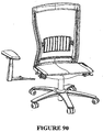
- Figure 1 illustrates an office chair 10 including a main assembly having a seat portion 14 and a back portion 16.
- the seat portion 14 and the back portion 16 are supported above the ground by a supporting frame including a wheeled base 18 and a central support column 20.
- the central support column 20 houses a pneumatic spring (not shown) for height adjustment of the seat portion 14 in conventional fashion.
- the pneumatic spring is connected to the main transom 22 of the chair which is illustrated in Figure 4.
- the main transom 22 extends transversely across the chair and is connected to the pneumatic spring by way of central spring connection ring 23.
- Figure 1 also illustrates two detachable arm assemblies 24.
- the arm assemblies 24 each include an upper armrest 26 which is padded for user comfort.
- Each aim assembly 24 includes an upright support structure 28.
- the armrest 26 is mounted to the upper end of the upright support structure 28.
- the lower end of the upright support structure has an elongate attachment portion 30 extending inwardly therefrom at a downwardly inclined angle relative to the upright support structure 28.
- the elongate attachment portion 30 is releasably engaged within one end of the main transom 22.
- the manner of attachment is not significant to the present invention and the reader may refer to our co-pending Patent Application US Serial No..........., the details of which are incorporated herein by reference.
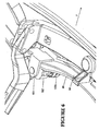
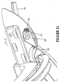
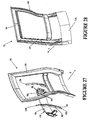
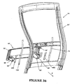
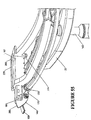
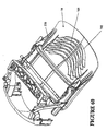
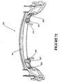
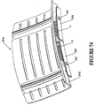
- the back portion 16 is defined by a peripheral frame 34 which is approximately rectangular in shape, as shown in Figure 2.
- the peripheral frame 34 has a mesh fabric stretched over.
- a lumbar support mechanism 36 is provided within the opening defined by the rectangular peripheral frame 34.
- FIG 2 illustrates more clearly the form of the peripheral frame 34.
- the peripheral frame 34 is constructed of a flexible plastics material such as injection moulded reinforced polyester.
- the peripheral frame 34 is of integral construction and comprises two upright members 38, a top beam 40 and a bottom beam 42.
- the upright members 38 are bowed with a gentle serpentine curve sweeping forwardly in the upward direction and then rearwardly beyond the lumbar region. This is a shape which is comfortable to the chair occupant.
- the upright members 38 include channels 44 which are open in the direction facing rearwardly as shown in Figure 28.
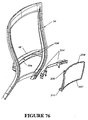
- the upright members 38 are also joined by an intermediate back beam 46.
- the back beam 46 supports the lumbar support mechanism 36.
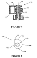
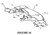
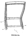
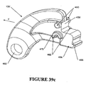
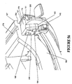
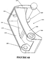
- the back attach casting 48 is an integrally cast component as shown in Figure 2b.
- the back attach casting 48 includes two pairs of sprigs 50 which engage with aligned apertures 52 provided at the bottom of the upright members 38. This enables the lower region of the peripheral frame 34 to be securely fixed to the back attach casting 48.
- An additional snap fitting (not shown) may be provided.
- the back attach casting 48 also includes 2 pairs of opposed walls 54 on opposite sides (more clearly seen in Figure 27). Each pair of spaced walls 54 defines a forwardly extending channel 64 in which a spring carrier 60 is received. Each pair of opposed walls 54 includes aligned slots 56.
- the spring carrier 60 (to be described more fully in connection with Figure 27) has pins 62 on opposite sides to engage with the aligned slots 56.
- the back attach casting 48 includes two forwardly extending hollow projections 66.
- the hollow projections 66 each define a socket 68.
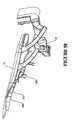
- Two back extension arms 70 are welded within respective sockets 68 of the hollow projections 66.
- each back extension arm 70 includes a forward nose portion 72 and a chin portion 74.
- An extension arm aperture 75 extends through the back extension arm 70 in a position rearwardly of the nose portion 72 and the chin portion 74.
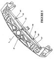
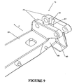
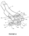
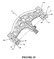
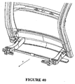
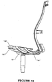
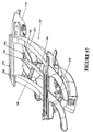
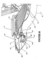
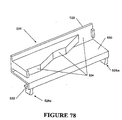
- FIG. 4 illustrates the main transom 22 which extends transversely across the chair as already explained.
- the main transom 22 is supported on a pneumatic spring at central spring support ring 23.
- the main transom is a beam-like construction of diecast aluminium with pivot features 76 formed at opposite ends. At each end, the pivot features comprise opposed supporting webs 78.
- the opposed supporting web 78 have rear aligned apertures 80.
- the extension arm aperture 75 of one of the back extension arms is aligned with the rear aligned apertures 80 on one side of the main transom to receive a main pivot pin (not shown) herethrough.
- the other back extension arm 70 is pivotally attached to the main transom 22 on the other side.
- Each back extension arm is pivotable about the associated main pivot pin and the recline axis R of the back portion 16 is thereby defined.
- a nose portion 72 is defined forwardly of each back extension arm 70.
- the nose portion 72 has two bosses 84 extending sideways from the flanks of the nose portion 72.
- the bosses 84 are receivable within facing slots 86 in the opposed supporting webs 78.
- Each of the facing slots 86 has a base formed therein.
- the bosses 84 move within respective ones of the facing slots 86.
- the bosses 84 will bottom out at the bases of the slots 86 thereby defining forward limits. This is referred to as the "forward active position"of the back portion 16.
- each back extension arm 70 includes a first abutment surface 88 for engagement with a second abutment surface 90 (see Figure 9) provided as part of the rear wall of the main transom 22.
- first abutment surface 88 engages with the second abutment surface 90
- the rearward recline limit of the back portion 16 of the chair will be thereby defined. It would not be possible for the chair portion 16 to recline back any further once the two abutment surfaces come into engagement although flexing of the peripheral frame is still possible in this position.
- the main transom 22 has a reaction surface 98 against which the first spring 94 engages.
- the reaction surface 98 is centrally disposed and has a depth corresponding to the depth of the first spring 94.
- the reaction surface 98 forms part of an integrally formed projection extending rearwardly from the main transom 22.
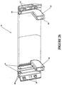
- Figure 27 illustrates a further exploded view of parts assembled with the peripheral frame 34.
- a back attach casting 48 is fixed to the back of the peripheral frame 34.
- the back attach casting 48 has two upright channels 64 arranged at either end, each defined by opposed walls 54.
- the opposed walls 54 have aligned slots 56 arranged therein for receipt of pins 62 provided on a spring carrier 60.
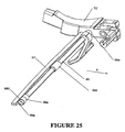
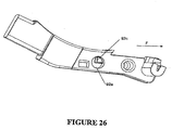
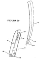
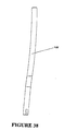
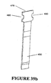
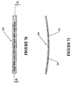
- the specific form of the spring carrier 60 is illustrated more clearly in Figure 29.
- the spring carrier 60 is in the form of an elongate member which is approximately square or rectangular in cross section with the pins 62 being arranged on opposite sides.
- One end of the member is provided with a rebate 124.
- the other end of the spring carrier is forked for pivotal connection with another linkage as will subsequently be explained.
- the forked end has aligned apertures 126.
- the rebate 124 has spaced threaded bores 130 provided therein.
- a leaf spring 128 has a lower end 131 shaped to be received within the rebate 124.
- the lower end 131 has two spaced apertures 133 provided therein. These apertures 133 align with the threaded bores 130 provided on the spring carrier so that the leaf spring 128 may be securely fastened to the spring carrier 60. From the lower end 131 in the upwards direction, the leaf spring 128 gradually increases in width with a slight tapering in thickness, although overall the leaf spring 128 is of generally elongate configuration as shown.
- the leaf spring 128 is constructed from high tensile spring steel.
- Figure 28 illustrates the assembled combination whereby each of the leaf springs lie against the back of the peripheral frame 34 in a respective channel 44.
- the peripheral frame 34 has a degree of flexibility.
- the leaf spring 128 will be caused to act against the lower portion of the peripheral frame thereby increasing its stiffness against rearward flexing.
- the two spring carriers act in unison in a manner which will be described in connection with Figures 30 to 34.
- the stiffness of the lower portion of the peripheral frame 34 can thereby be adjusted by adjustment of the position of the spring carrier 60.
- the channels 64 in which each of the spring carriers 60 are received are closed rearwardly by a rear wall 135 of the back attach casting 48.
- the rear wall 135 defines a stop against which the forked ends 125 of the spring carriers engage, thereby defining the maximum rotation of the spring carrier 60 and thus the maximum stiffness which can be imparted by the leaf spring 128 to the peripheral frame 34.
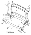
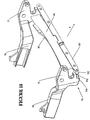
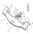
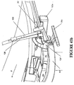
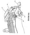
- Figure 30 illustrates the main elements of the recline mechanism.
- the back attach casting 48 has been removed for clarity, together with the right back extension arm 70.
- the left back extension arm 70 is shown in position pivotally connected to the main transom 22.
- the forked end 125 of each spring carrier 60 is connected to a push link 139.
- the lowerportion of the peripheral frame 34 has an access opening 143 to enable the push link 139 to engage with the forked end 125 of the spring carrier 60 disposed within the assembled back attach casting 48.
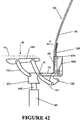
- the forward end of the push link 139 is connected to a drive link 141 (see Figure 30) which is one element of a four bar linkage which will be understood more fully from a consideration of the schematic illustration of Figure 31.
- FIG 31 illustrates only one four bar linkage and it will be apparent to the reader that two such four bar linkages are provided, one on each side of the chair 10.
- the drive link 141 extends at an inclined upwards angle from its connection with push link 139.
- the drive link 141 is curved along its length with the centre of the curve being disposed rearwardly and upwardly.
- the drive link 141 is mainly of rectangular cross section.
- the drive link 141 is pivotally connected at an intermediate location along its length to the main transom 22 for pivoting motion about the recline axis R. Specifically, the drive link 141 is pivotally connected to lie adjacent to the outer one of the opposed supporting webs 78 of the main transom 22. A common pivot pin (not shown) interconnects both of the opposed supporting webs 78, the back attach arm 70 through aperture 75, and the drive link 141.
- the main transom 22 forms another element of the four bar linkage. As has already been explained, the main transom 22 is centrally mounted to the supporting frame at the top of the central support column 20 which incorporates a height adjustable pneumatic spring 145. The height adjustment 145 is selectively operable by the chair occupant. However, the main transom 22 is normally stationary relative to the supporting frame.
- the seat portion 14 is slidably mounted to a seat guide 149 in a manner which will be described more fully in connection with Figures 55 to 60.
- the seat guide 149 thereby forms another element of the four bar linkage.
- the upper end of the drive link 141 is pivotally connected to the seat guide 149.
- Another link in the form of a front support link 151 interconnects the seat guide 149 and the main transom 22.
- the front support link 151 is of generally rectangular cross section and, like the drive link 141 is curved along its length with the centre of curvature disposed upwardly and rearwardly.
- both ends of the drive link 141 are forked.
- the lower end is forked to accommodate the lower end of the push link 139.
- the upper end of the drive link 141 is also forked.
- the seat guide also has a dependent lobe 155 as shown in Figure 32.
- the forked upper ends of drive link 141 are disposed on each side of the lobe 155 and the inner fork is pivotally connected between the lobe 155 and the side wall of the seat guide 149.
- the outer fork is fanned in shape for aesthetic reasons and the pivotal connection does not extend therethrough.
- the upper end of the front support link 141 is also forked with the inner fork being pivotally connected between a seat guide 149 and another lobe 157 (see Figure 32), with the outer fork being of fanned shape.
- the lower end of the front support link 151 is pivotally connected on the outside of the outer one of the opposed supporting webs 78 (see Figure 4) by means of a pin (not shown) extending through aligned forward apertures 153 on the forward end of the opposed supporting webs 78. It will be appreciated that the connection of the lower end of the drive link 141 and the front support link 151 are blind connections as shown for aesthetic reasons.
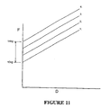
- the occupant's weight will be taken up by a spring tension in leaf spring 128 as it flexes against the back of the peripheral frame 34. This has the effect of stiffening the back portion against rearward flexing. It will be appreciated that the tension imparted to leaf spring 128 will depend upon the weight of the user W applied to the seat portion 14. The greater the weight W, the greater the tension taken up by the leaf spring 128 and thus the greater the degree of stiffness imparted to the leaf spring 128 to resist rearward flexing of the peripheral frame 34. Accordingly, the stiffness of the peripheral frame 34 will be adjusted according to the weight W of the chair occupant.
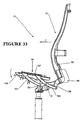
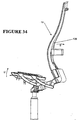
- Figure 33 illustrates the downward motion of the seat guide 149 as the user applies weight W. When the occupant alights from the chair, the seat portion 14 will move upwardly as indicated by arrow U in Figure 34.
- the gentle serpentine shape of the peripheral frame 34 is designed to correspond with the shape of the occupant's spine for the comfort of the occupant.
- the ergonomies of the chair are further enhanced because this enables the occupant to exercise his spine.
- the general health of a person's spine is enhanced by movement.
- the stiffness of the back portion in rearward flexing is adjusted according to the occupant's weight. Therefore, within a certain range, the ease of rearward flexing will correlate to the weight of the occupant. Therefore, a light person will be able to obtain full benefit from the rearward flexing action by applying a light force against the peripheral frame.
- the chair is designed so that, the occupant will be able to obtain deflection through flexing in the range of 80 mm to 120 mm.
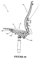
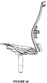
- Figure 35 illustrates the reclining action of the chair 10.
- the seat portion When the user applies their weight to the seat portion 14, the seat portion will move downwardly as already described and adopt a position just above the seat guide 149 as illustrated by the solid lines.
- the leaf spring 128 takes up a corresponding amount of spring tension whereupon the spring carrier 60 and the push link 139 will adopt a more or less fixed position relative to the back attach casting 48. Therefore, as the user leans against the back portion 16, the back attach casting 48, spring carrier 60, push link 139 act in unison driving the drive arm 141 to rotate in a clockwise direction through push link 139.
- the arrangement of the four bar linkage is such that the seat guide 149 will adopt a position with a net increase in height and with an increase in rearward tilt angle compared to the occupied position of the seat guide 149 before recline. In practice, there may be some slight shifting between the leaf spring 128, the spring carrier 60 and the push link 139.
- the occupant's weight W will be counteracting the recline action, together with the bias applied by the first and second recline springs 94,96.
- the weight of the occupant W will therefore be a variable factor in the case with which the back portion 16 reclines. If the adjustable second recline spring 96 is set at a constant level then a heavier person will encounter a greater resistance to reclining action than a lighter person. This establishes an automatic correlation between the weight of the person and the resistance to the reclining action. For a large proportion of people who fit within physical norms this automatic adjustment may be sufficient However people come in all different shapes and sizes and therefore additional adjustment is required through the use of the clamping adjustment as explained previously. For example, a very tall, light person may obtain leverage through their height which makes the back portion 16 fall back too easily against their low weight W.
- the net increase in height also has the advantage of raising the occupant during recline so that the eye level of the chair occupant can be maintained even though he is undergoing a reclining action.
- the peripheral frame will still be able to flex under additional force applied by the chair occupant.
- the peripheral frame will be capable of undergoing deflection in the range of 80 mm to 120 mm.
- the weight of the user against the back portion will bring about a deflection of up to 20 mm. Therefore, once the recline limit is reached, the occupant still has further deflection available through flexing of the peripheral frame in the range of 60 to 100 mm.
- the seat portion 14 is only supported by the seat guide 149 at a rear portion thereof with a forward portion being unsupported.
- a transition point 161 is disposed behind the forward edge 160 of the seat guide 149.
- the transition point 161 marks the boundary between the planar upper surface 178 of the scat guide 149 and a forwardly inclined lead surface 285.
- the seat portion 149 is foldable transversely at this location.
- the transition point 161 hence defines the division between the rearward portion and the forward portion of the seat portion 14. Since the seat portion 14 is slidable forwardly and rearwardly for seat depth adjustment as will be explained in connection with Figures 55 to 60, the division between rearward portion and forward portion of the seat will vary as a function of seat depth.
- Figure 35 illustrates the changing curvature of the back portion 16 and seat portion 14 in recline.
- the solid lines indicate the forward active position in the occupied configuration.
- the dotted lines illustrate the reclined position.
- the seat guide 149 attains a net increase in height and an increased rearward tilt. This effectively cups the occupant's derrière, negating any inclination to slide forwardly during the recline action.
- the seat portion 14 is also flexible and since the occupant's derrière is undergoing a net increase in height together with increased rearward tilt, a greater amount of weight from the occupant's legs will be brought to bear against the forward portion of the seat portion 14. Accordingly, the seat portion 14, will be allowed to fold transversely at the transition point 161 on the seat guide 149.
- transition point 161 approximately corresponds to the gluteal fold of the occupant's derriere. Therefore, during recline, the occupant's derriere will be cupped between the rear portion of the seat portion 14 and a lower region of the back portion 16 while the forward portion of the seat drops forwardly under the weight of the occupant's legs. Locating the transverse fold at the gluteal fold of the occupant ensures that undesirable pressure will not be brought to bear against the back of the occupant's legs.
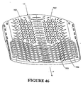
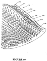
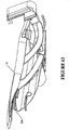
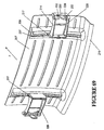
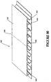
- FIG 46 is a perspective view of a preferred form of the seat portion 14.
- the seat portion 14 is in the form of a flexible plastic panel, whose flexibility is enhanced by the arrangement of slots as indicated.
- the plastic panel may be injection moulded plastic such as TPR.
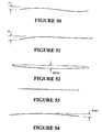
- Figure 50 is a longitudinal section through the middle of the seat panel 14 illustrating the general curved configuration with a rolled over edge. The edge drops by an amount of dimension A.
- Figure 51 illustrates the side edge of the seat panel 14. The side edge is flatter than the middle section. Additionally, the forward edge dips down a dimension B, where B is larger than A.
- Figure 52 illustrates a transverse sectional view at about 150 mm from the rear of the seat whereas the view Figure 53 depicts the transverse cross sectional view 120 mm from the front edge.
- FIGs 50-54 are merely indicative of the moulded shape of the seat panel 14.
- the seat panel is also flexible to accommodate the occupant and to respond to movement of the occupant
- the arrangement of slots in the seat panel 14 as shown in Figure 46 is designed to enhance the flexibility of the seat panel 14.
- the mangement of slots in the forward half of the panel is designed to facilitate folding along the transverse fold.
- the slots are arranged in a series of spaced sinuous lines 163 extending transversely across the seat portion 14 with the central part being shaped convex forwardly with the outer parts being shaped concave forwardly.
- the lines of slots 163 are discontinuous.
- the seat portion 14 is dished at least in a rearward part.
- the series of spaced sinuous lines 163 enables the seat panel 14 to fold transversely, even though the rear part is dished.
- the slotted pattern 164 is such as to extend diagonally across the corners following the curvature of the transverse sinuous lines 163: In this way, if the user moves a leg to one of the forward corners then the diagonal arrangement of the slots 164 will enable the forward corner to fold under the weight of the occupant's leg.
- the slots are arranged in a pattern to accommodate the ischial protuberosities of the occupant.
- the slotted pattern provides two spaced, approximately rectangular zones 162 whose locations correspond to the ischial protuberosities of the occupant (assuming the occupant is properly seated with an appropriate seat depth adjustment).
- the two zones 162 interrupt the transverse slot pattern.
- Each zone is comprised of slots arranged in a series of longitudinally extending, transversely spaced sinuous lines.
- the lines of slots are discontinuous.
- the longitudinal arrangement of slots in each zone 162 enables the remaining material between the longitudinal lines of slots to spread apart thereby creating pockets, one for each ischial protuberosity of the seat occupant.
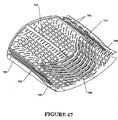
- Figure 47 illustrates longitudinal stiffening webs 165 provided on the underside of seat panel 14. There are five stiffening webs, two disposed along the opposite side edges. A further two are disposed on each side at 60 mm from the corresponding side edge. Another is centrally disposed. The longitudinal stiffening webs are constant in height from the back edge of the seat portion until the taper start point 164 from where they progressively reduce in height until a taper finish point 166. (The central web however terminates early)
- the seat portion 14 accommodates a depth adjustment as will be explained in connection with Figures SS to 60.
- the seat portion folds transversely about the transition point 161 on the seat guide 149.
- the depth of the stiffening ribs in the region at the transition point 161 is shallow thereby offering little resistance to flexing. Generally, this suits a small, light weight person. However, for a larger person, the seat panel will be disposed further forwardly in relation to the seat guide 149. The depth of the stiffening ribs in the location of the transition point 161 will be deeper, thereby offering increased resistance to bending.
- the start taper point 164 is at a position which corresponds to the transition point 161 when the seat is at its full forward position to suit a large person.
- the taper finish point 166 is at a position corresponding to the transition point on the seat guide 149 with the seat in the rear most position to suit a small person.
- the taper start point 164 and the taper finish point 161 define a transition zone therebetween.
- the transverse fold may be disposed at a range of positions within the transition zone, dependent on seat depth adjustment.
- the pattern of transversely extending sinuous lines of slots extends for at least the transition zone.
- Figure 47 also illustrates transverse stiffening webs 168.
- the stiffening webs 168 follow the pattern of the transversely arranged sinuous slots 163.
- the seat panel is moulded in a dished shape.
- the transverse stiffening webs 168 help to retain the shape of the front part without inhibiting the transverse folding action under the weight of the user.
- a back web is provided along the back of the seat panel 14 on the underside as shown in Figure 47.
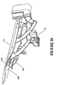
- Figure 49 illustrates in greater detail the arrangement of features along one side edge.
- a series of spacer blocks 270 extending in a line between the taper start point 164 and the taper finish point 166.
- a wedge-shaped gap 272 widening towards the top.
- the seat panel 14 sits atop a seat carriage 167.
- a rear part of the seat panel 14 is secured atop the seat carriage 167 so that forwardly of the seat caniage 167 mere will be a gap between the seat guide 149 and the seat panel 14.
- the spacer blocks 270 extend into this gap. As the seat panel 14 folds, the spacer blocks 270 bear against the top of the seat guide 149. It can be seen that the spacer blocks 270 also taper off in height as shown. Furthermore, the spacer blocks 270 will define the maximum curvature of the seat panel along the transverse fold since once the side walls of the wedge-shaped gaps 272 engaged with each other, further curvature will be prevented.
- a guard also extends alongside the spacer blocks 270 to provide a barrier against the user's fingers being trapped.
- FIG 55 illustrates the main elements of the seat depth adjustment mechanism.
- the seat guide 149 is one of the elements of the four bar linkage discussed previously.
- the two seat guides 149 provide a guide for a slidable seat carriage 167.
- a rear part of the seat panel 14 illustrated in Figures 47-54 is attached to the carriage 167.
- the rear half only of the seat panel 14 is attached to the seat carriage 167.
- the seat panel 14 may be moved forwardly and rearwardly by the sliding action of the seat carriage 167 on the seat guide 149.
- a longitudinally extending rib 274 engages within a channel 278 (see Figure 55) of the seat carriage 167 and the tab 276 is a snap fit connection within the recess 280 located rearwardly on the seat carriage 167.
- four spaced retention tabs 282 engage against soffit 284 of the carriage 167. The retention tabs 282 retain the seat panel 14 engaged with the seat carriage 167 while the longitudinal rib is the main load bearing part.
- Figure 55 also illustrates the controls for the height adjustable pneumatic spring 145.
- a height adjustment control lever 169 is mounted for pivotal motion on the outside of the right hand seat guide 149.
- the pivotal motion of the height adjustment control lever 169 is replicated by the height adjustment control actuator 170 which is connected to one end of a control cable 172.
- the other end of the control cable 172 is connected to the top end of pneumatic gas spring 145.
- the control cable 172 releases the gas spring in the conventional known manner and the chair occupant adjusts the height of the seat portion 14 to suit his requirements.
- FIG 56 is a further detailed view of the left side of the seat carriage 167.
- the seat guide 149 includes a plastic seat guide liner 176.
- the seat guide liner is of elongate configuration with an upper glide surface 178 and an inner glide surface 180.
- the inner glide surface 180 is spaced from the inner side of the metal part seat guide 149 with a peripheral wall 182 maintaining the inner glide surface 180 in spaced configuration therefrom.
- the seat guide liner 176 is thereby hollow behind the inner glide surface 180.
- the upper glide surface 178 is received within a rebate in the upper surface of the metal part of the seat guide 149 in order that the upper glide surface 178 is contiguous with the upper surface of the metal part of the seat guide 149.
- the seat guide liner 176 provides a bearing surface for easy sliding of the seat carriage 167.
- the seat guide liner 176 may be comprised of nylon or acetal. The reader will appreciate that a symmetrical arrangement is provided on the right hand side of the chair.
- the seat carriage 167 is of unitary cast aluminum construction and comprises two spaced slides, each of which engages with a respective seat guide 149.
- Each slide is of a generally L-shaped configuration having an upright glide surface 186 on an inner wall for sliding engagement with the inner glide surface 180 and a horizontal glide surface 187 for engaging with the upper glide surface 178.
- the carriage is of a symmetrical configuration about a central upright longitudinally extending plane of the chair.
- the two slides provided on the right and left are thereby of opposite configuration.
- the two slides are joined by transversely extending bearers 190.
- the inner glide surface 180 is moulded with a series of archlets which extend from the inner glide surface 180.
- the archlets 184 protrude inwardly (relative to the chair as a whole) to bear against the upright glide surface 186 of the seat carriage 167.
- the archlets may be arranged in any pattern but preferably they are staggered along the length of the inner glide surface 180.
- Both of the seat guide liners 176 have inwardly extending archlets bearing against the associated upright glide surfaces of 186 of the carriage 167.
- the archlets 184 thereby act against the carriage to centre the carriage 167 centrally between the two seat guides 149.
- the resilient archlets 184 will take up any slack between the upright glide surface 186 and the inner glide surface 180. This assists to prevent jamming of the carriage 167 within the seat guides 149.
- Figure 57 illustrates the control for seat depth adjustment.
- the inner wall of both slides 185 have a lower edge with a series of spaced notches 192.
- a seat depth adjustment bar 194 has two teeth 196, each arranged at opposite ends of the bar 194.
- the seat depth adjustment bar 194 is moveable between a latched position in which the teeth 196 engage in a respective one of the notches 192 and an unlatched position in which the carriage 167 is free to slide along the seat guide 149.
- the seat depth adjustment bar 194 is controlled by a seat depth adjustment button 200.
- the seat depth adjustment button 200 is moveable from the latched position against the bias of a spring (not shown) to move the seat depth adjustment bar 194 into the unlatched position whereby the teeth 196 no longer engage in the notches 192.
- the seat carriage 167 can then be slid to an appropriate seat depth whereupon the occupant releases the seat depth adjustment button 200 to enable the teeth 196 to engage with the closest of the notches 192.
- a seat depth stop 174 ( Figure 55) formed as a dependent projection from the seat carriage 167 determines the forward position of the seat carriage 167 as it engages with the adjustment bar 194 or sleeves 158 receiving the ends of the adjustment bar 194.
- the rear limit is defined by a pin (not shown) extending inwardly from the seat guide 149 to engage within a slot of the seat carriage 167.
- the slot is machined to define a stop to engage with the join in the rear most position of the seat portion.
- Figures 58 and 59 illustrate the extended and retracted positions respectively of the seat portion 14.
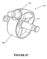
- FIG 61 and 62 illustrate a modified form of the seat carriage 167 and the seat guide 149'.
- the seat carriage 167' is a unitary cast aluminum construction with two spaced slides as explained with the first embodiment, each of which engage with a respective seat guide 149'.
- the two slides are joined by a unitary deck construction having a series of transversely extending ribs as shown.
- the seat guides 149' include seat guide liners 176' having an upper glide surface 178' and an inner glide surface 180' to slidably engage with the respective slide of the seat carriage 167'.
- the seat guide liners 176' will be described in greater detail in connection with Figure 62b and 62c.
- the second embodiment of the chair includes a control lever 169' on the right hand side (left hand side of the figure).
- This lever 169' is a dual actuator for both the seat height adjustment and seat depth adjument.
- the control lem 169 is mounted for pivotal motion on the outside of the right hand seat guide 149'.
- the control lever 169' effects the operation of a dual actuator 170' mounted on the inside of the right band seat guide 149'.
- the actuator 170' includes a first actuator portion 170a and a second actuator portion 170b.
- the first actuator portion 170a is connected to cable 172' which connects to the top end of a pneumatic gas spring 145'. As the user raises the control lever 169', the control cable 172' releases the gas spring in the conventional known manner and the chair occupant adjusts the height of the seat portion 14 to suit his requirements.
- the second actuator portion 170b is connected via cable 488 to a pivotable pawl 490.
- the pawl is engageable between any one of a plurality of teeth provided on a rack 492 formed on the underside of the seat carriage 167'.
- the pawl and rack arrangement 490, 492 is also duplicated on the other side of the seat carriage 167' as shown in Figure 62.
- the cable 488 passes from the right hand pawl 490 around to the other side of the seat carriage 167' for simultaneous operation of the two pawls 490.
- the user depresses the control lever 169' to operate the second actuator portion 170b to pivot the two pawls against a bias out of engagement with the teeth of the associated rack 492.
- the seat carriage 167' can then be slid to an appropriate seat depth where upon the occupant releases the control lever 169' to enable each of the pawls 490 to engage with the associated rack 492.
- Figure 61 also illustrates a forward cover 495 which is shaped in a serpentine manner for aesthetic purposes to extend in front of the main transom 22'.
- the cover 495 is joined to the seat guides 149' on each side through the use of integrally formed bosses 497 which can be seen in Figure 62b and Figure 62c.
- the seat guide 149' illustrated in Figure 62b includes a seat guide liner 176'.
- the seat guide liner 176' includes an upper glide surface 178' and an inner glide surface 180'.
- the inner glide surface 180 is formed with a series of spaced integral resilient projections 500.
- the integral resilient projections 500 are directed inwardly.
- the seat guide liner 176' is supported on a metal supporting part of the seat guide liner as shown in Figure 62c.
- the inner glide surface 180 is disposed in spaced configuration from the inside of the supporting part of the seat guide 149'.
- the supporting part of the seat guide 149' includes three spaced rests 502.
- the integral resilient projections 500 are shaped like ramps, the ends of which engage against the associated rest 502. The majority of the inner glide surface 180' is thereby resiliently held in spaced configuration from the supporting part of the seat guide 149'.
- This gap might be one in which the occupant can get their fingers caught.
- a movable comb like formation 504 is incorporated into the seat guide liner 176' as shown in Figure 62b.
- the comb like formation 504 has an upper surface continuous with the upper glide surface 178' and dependent prongs 506 which extend downwardly. The prongs are receivable into a series of corresponding pits 508 formed in the metal supporting part of the seat guide 149'.
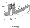
- the movable comb like formation 504 is resiliently flexible and would normally extend to fill the gap between the leading edge 285 of the seat guide 149' and the dependent spacer blocks 270'. For instance, see Figure 63 although in Figure 63, the occupant's weight is not yet bearing on seat panel 14 and thus the seat panel 14 has not yet come to rest on top of the comb like formation 504.
- the dependent spacer blocks are not visible in this view because the seat panel 14 has a peripheral guard to prevent jamming of fingers in the V-shaped gaps of the spacer blocks 270'.
- the spacer blocks 270' will come to bear against the comb like formation 504 which will deflect as the seat portion 14 folds about the transverse fold.
- the comb like formation 504 presents an additional guard to mitigate the likelihood of user's fingers being caught between the seat panel 14 and the seat guide 149'.
- the comb like formation 504 does not interfere with the transverse folding of the seat panel 14.
- Figure 63 illustrates the seat panel 14 in its inward retracted position whereas Figure 64 illustrates the seat panel 14 located in its outer most extended position.
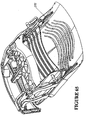
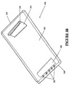
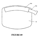
- Figure 89 illustrates in schematic form, the underside of the slotted seat panel 14.
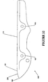
- a scabbard which is curved in form.
- the scabbard 350 houses an instruction slide 352 which is also curved and slides in and out of the scabbard at one end. From above, the instruction slide 352 has printed indicia thereon providing user instructions to the seat occupant.
Abstract
Description
- The present invention relates to a flexible or foldable panel for a seat such as a chair or a stool. In particular, although not exclusively, the invention relates to a flexible panel for a reclinable office chair. A seat depth adjustment mechanism is also described, While the invention is described in terms of commercial office chairs, the invention may have application to any other type of seating such as public seating for theatres, aircraft or domestic seating.
- When a person sits in a chair, there are two boney protuberances on which the person sits. These are reffered to as the ischial protuberositises. It can be uncomfortable to sit on these for a period of time and therefore seats such as chairs and stools are generally padded with one or more layers of foam for user comfort. Depending upon the quality of the foam, the user can still experience some discomfort after a period of time because once he sinks down into the foam, he still may encounter a greater resistance bearing on the ischial protuberosities, compared to other parts of his derriere.
- It is an object of at least an aspect of the present invention to provide a flexible seat panel which more comfortably accommodates the occupant's ischial protuberosities.
- In office chairs, it is desirable to have seat portions in which the forward portion is deflectable under the weight of the occupant See for example US Patents Nos. 5,050,931 and US 4,498,702. US Patent No. 5,050,931 has a generally flexible seat portion but a relatively complex spring mechanism is required in order to upwardly bias the forward portion and prevent it from unduly sagging under the occupant's weight The arrangement shown in US Patent 4,498,702 is a cumbersome arrangement in which a separate forward portion of the seat portion is connected to a rearward portion of the seat portion by leaf springs. The prior art suffers from the disadvantage that in order for the seat portion to have sufficient strength, complex spring mechanisms are required to prevent the forward portion from unduly sagging under the weight of the occupant.
- It is yet another object of at least an aspect of the present invention to provide a flexible or foldable seat panel which alleviates the requirement for a complex spring mechanism to resist undue sagging of the forward portion of the seat portion.
- As the reader will appreciate, people come in a great deal of different shapes and sizes. As the chair market stands at present, office chairs are required to cater for a large range of occupant sizes. A commonly available adjustment is seat depth adjustment as illustrated in US Patent 5,871,258. This US patent also illustrates that the forward portion of the seat portion may be deflectable under the occupant's weight thereby defining a transverse fold line. However, the fold line is disposed the same distance from the front of the seat portion, irrespective of the seat depth position which does not cater for different sizes of seat occupants. Furthermore, another disadvantage of this prior art arrangement is that a complex spring arrangement is required to upwardly bias the forward portion of the seat portion. In one embodiment, the user is required to adjust the spring force to suit his requirements and in another embodiment the spring force is non-adjustable.
- Further seat panels are described in US-A-5 664 835 and US-
A-4 418 958. - It is therefore an object of at least an aspect of the present invention to provide a means for resisting flex of the forward portion of the seat portion which offers a resistance correlating to the seat depth position.
- In accordance with a first aspect of the present invention there is provided a seat portion for a seat according to
claim 1. - Preferably the panel is of a unitary construction which is weakened in specific locations enabling the zones to form pockets which accommodate the ischial protuberosities of an occupant sitting in the seat. Preferably, a plurality of weakeners are provided to provide the zones with increased "give" in response to an occupant sitting in the seat. The weakeners may be in the form of apertures. For example, the seat panel may be perforated. However, a slotted pattern is the most preferred construction. An alternative construction is to provide weakeners, each of which is in the form of a reduction in thickness in the specific location where it is desired to increase flexibility.
- The seat portion may also include a forward portion integrally formed with the back portion to form a unitary shell to support the occupant. The seat panel might be provided with an overall pattern of weakeners to enhance flexibility. The zones may have an increased concentration of weakeners compared to the remainder of the seat panel. For example, a preferred overall pattern is a pattern of weakeners arranged as a series of spaced transversely extending sinuous lines. Preferably the pattern of transversely extending sinuous lines is interrupted by the two zones. The zones may be of any shape such as circular, square, although a rectangular shape is preferred which allows some flexibility as to the particular location of the seated occupant relative to the seat panel and also allows for the fact that chair occupants come in an different shapes and sizes.
- In a most preferred form of the invention, the zones also include a pattern of weakeners arranged in spaced longitudinally extending sinuous lines. Preferably, the weakeners in the zones are slots. Additionally, the longitudinally extending lines within the zones may be more closely spaced than the transversely extending lines in the remainder of the seat panel. Moreover, it is also preferred that the frequency of the repeating wave of the longitudinally extending lines in the zones is greater than the frequency of the transverse sinuous lines in the remainder of the seat panel.
- As mentioned above, the seat panel is preferably an integral one piece panel incorporating the rear portion and the forward portion. Additionally, the seat panel could be integral with the back panel incorporating an integral hinge to allow flexibility between the back panel and the scat panel. The seat panel is preferably of moulded plastics construction which is moulded in a specific shape to enhance user comfort. In particular, the rear of the seat panel may be dished. Furthermore, at approximately one third of the length of the seat panel along the longitudinal centreline, there may be provided a transverse plateau portion which is generally flat. Forwardly of the transverse plateau portion, preferably the seat portion dips downwardly. Additionally, the corners may also dip downwardly. In a most preferred form of the invention the panel essentially comprises a sheet. The sheet may incorporate stiffening webs on the underside thereof extending in either the transverse or longitudinal direction. Preferably, the stiffening webs extending in the transverse direction follow the pattern of spaced transversely extending sinuous lines. The transverse webs may be disposed in between the lines of weakeners.
- In accordance with a second aspect of the present invention there is provided a seat panel for a seat comprising a rear portion to support the occupant, the rear portion having a longitudinal centerline and incorporating two zones either side of the longitudinal centerline, there being surrounding portions surrounding the zones, wherein the panel is of a construction which provides enhanced flexibility in each of the zones compared to the surrounding portions and wherein a substantial portion of the panel, apart from the zones is provided with a pattern of weakeners arranged in a series of spaced sinuous lines, interrupted by the zones.
- The flexible panel described in the abovementioned aspect may incorporate any of the preferred features described in accordance with the first aspect of the invention as set out above.
- In accordance with the third aspect of the present invention there is provided a seat construction for supporting a seat occupant, the seat construction including: a seat portion which is foldable about a transverse fold under the weight of the occupant; a seat depth adjustment mechanism to adjust the position of the seat portion in and out over a range of positions between an extended position and a retracted position, wherein the seat portion incorporates a resistance to folding which increases as the seat position is adjusted towards the extended position.
- In a preferred form of the invention, the seat depth adjustment mechanism may include a seat guide, the seat portion being moveable relative to the seat guide with the seat portion being transversely foldable relative to a fixed portion of the seat guide such that the transverse fold shifts by an amount corresponding to the depth adjustment of the seat. Accordingly, the transverse fold may lie anywhere within a predetermined transition zone on the seat portion.
- The construction of the seat portion may vary over the transition zone in order to provide the corresponding adjustment of the resistance to folding. For example, the thickness of the seat portion may increase over the transition zone in the direction towards the rear of the seat portion. The transition and thickness may be a stepped increase or gradual ie tapered seat portion.
- In a preferred form of the invention, the seat portion incorporates longitudinally extending stiffening webs. Suitably, the longitudinal webs are provided on the underside of the seat portion. The longitudinally extending webs may increase in girth over the transition zone in the direction towards the rear of the seat. For example, the webs may increase in height or alternatively increase in thickness. In a most preferred form of the invention, the longitudinally extending webs begin at nil thickness at the beginning of the transition zone and gradually increase m height in the rearward direction, over the transition zone, the longitudinal webs being maintained of a uniform height rearwardly of the transition zone. Preferably there are four longitudinally extending stiffening webs. Preferably, the seat portion is one piece. In a most preferred form of the invention, the seat portion is an integral moulded plastic panel construction.
- The seat depth adjustment mechanism may be selectively operable by the seat occupant. The position of the seat portion may be adjustable in increments so that the seat portion may adopt any one of a finite number of positions between the extended and the retracted position. Preferably, the seat depth adjustment mechanism includes a lock having a locked configuration and an unlocked configuration with the seat depth adjustment mechanism being normally biased towards the locked configuration with an actuator provided to selectively move the lock to the unlocked configuration.
- In a preferred form of the invention, the seat depth adjustment mechanism includes a seat carriage slidably supported on the seat guide. The seat carriage may incorporate the seat portion. However, in a preferred form of the invention, the seat portion is a discrete member attached to the seat carriage. In a most preferred form of the invention the seat portion is in the form of a flexible panel fixed to the seat carriage.
- The panel further includes a plurality of dependent spacers disposed forwardly of the seat carriage. Preferably, the spacers bear against the seat guide when the occupant's weight is brought to bear on a forward part of the seat portion. Preferably the spacers are arranged in a longitudinally extending line and gaps may be provided between adjacent spacers such that when the sides or edges of the spacers on each side of the gaps engage, the maximum curvature of the transverse fold is defined. Most preferably, the gaps are in the form of invoked V-shaped gaps such that on maximum curvature of the transverse fold, the sides of each gap engage with each other to close the gap. Most preferably, the spacers comprise a series of blocks which extend longitudinally over the length of the transition zone. Preferably, the blocks also reduce in height towards the front of the seat portion. The top of the blocks may define a taper.
- In a most preferred form of the invention, the seat carriage is slidably supported on two guides arranged on opposite sides of the seat construction. Accordingly, there may be two sets of spacers, each of which bear against a respective seat guide.
- As has been explained in accordance with the first aspect of the invention, the seat portion may comprise a flexible panel which is moulded into a three dimensional shape to enhance comfort for the occupant. The features of three dimensional shape described above in accordance with the first aspect of the invention may be applied to the aspect of the invention defined above. Additionally, the seat panel may incorporate a pattern of weakeners to enhance the flexibility and the foldability of the seat panel as discussed in connection with the foregoing aspects of the invention.
- In accordance with another aspect of the present invention there is provided a seat construction for supporting a seat occupant including: a seat portion which is foldable about a transverse fold under the weight of the occupant; a seat depth adjustment mechanism to adjust the seat portion in and out over a range of positions between an extended position and a retracted position, the seat depth adjustment mechanism including a seat guide relative to which the seat portion is adjustably moveable, wherein the seat portion folds transversely about a fixed portion of me seat guide.
- Accordingly, a transition zone may be defined in the seat portion between the location of the transverse fold in the retracted position of the seat portion and the location of the transverse fold in to the extended position of the seat portion. Preferably, the seat portion is a one piece plastics panel provided with a patterns of weakeners, the pattern extending for at least the width of the transition zone to enhance the transverse foldability of the seat panel over the transition zone. The pattern of weakeners may incorporate any of the features described above in accordance with the first aspect of the invention. The preferred form is a series of spaced lines of discontinuous slots, the lines extending sinuously in a transverse direction with the lines curving convex forwardly across the centreline of the seat portion.
- Additionally, the seat portion may be carried by a seat carriage which is moveable relative to the seat guide. The seat portion may be in the form of a flexible panel which incorporates dependent spacers as described in connection with the preceding aspect of the invention.
- In accordance with still another aspect of the present invention there is provided a flexible seat panel for supporting a seat occupant, the seat panel being foldable about a transverse fold under the weight of the occupant wherein the panel incorporates longitudinally extending stiffening webs which, for at least a portion of their length increase in girth in the rearward direction.
- The longitudinal webs may be variable in either width or height or a combination of both over said portion of their length. Preferably, the webs taper in height in the rearward direction.
- The panel may be foldable about a transverse fold anywhere within a transition zone disposed in an intermediate location of the panel. Preferably, the webs offer increased resistance to folding as the transverse fold is moved in the rearward direction over this transition zone.
- The above aspect of the invention may incorporate any of the features described in connection with the foregoing aspects.
- In accordance with a further aspect of the present invention there is a provided a seat depth adjustment mechanism including: a seat guide; and a seat carriage slidably supported on the seat guide, the seat carriage being slidable between a retracted position and an extended position, wherein the seat guide has a guide glide surface and the seat carriage has a carriage glide surface, the guide glide surface and the carriage glide surface being in sliding engagement with each other, wherein one of the glide surfaces is formed by a liner having integral resilient projections engaging the other of the glide surfaces.
- Preferably the liner is in the form of a plastic liner having integrally formed projections. The plastic liner may be moulded. The resilient projections may be of any shape. In the preferred form of the invention the resilient projections are in the form of archlets. Preferably, the archlets are formed with ends which are contiguous with the remainder of the glide surface from which they project with the side edges of the archlets being spaced therefrom, thereby defining arch-shaped openings on each side. Preferably, the archlets are arranged in a staggered pattern.
- Preferably, the liner is incorporated into the seat guide. However, this is not essential and the liner may alternatively be incorporated into the carriage. In a preferred form of the invention, there are two seat guides on opposite sides of the carriage, slidably supporting the carriage. In this form of the invention, each of the seat guides may incorporate a liner, the two liners being a mirror image of each other. Each of the plastic liners may be supported by a metal part of the guide.
- Where two liners are incorporated into respective seat guides, the glide surfaces with the projections may define two facing uptight glide surfaces engaging against upright glide surfaces on opposite sides of the carriage. Preferably, each glide surface with the projections is maintained in spaced configuration from the associated metal part of the seat guide. This also provides a measure of resiliency for the glide surface with projections. Preferably, the glide surface with projections is maintained in spaced configuration front the associated scat guide by a peripheral wall extending from the seat guide to the glide surface with projections. It will be appreciated that this arrangement with two facing glide surfaces with projections is advantageous since it centres a carriage between the two seat guides. The arrangement also takes up any slack between the carriage and the adjacent seat guides, thereby reducing the risk of jamming of the seat carriage between the seat guides.
- The liners may also include upper glide surfaces on which the carriage is supported. These upper glide surfaces may be provided with or without resilient projections. Preferably, the liners are formed as integrally moulded plastic constructions including the upper glide surfaces and the upright glide surfaces, and being of L-shape in transverse section.
- The seat adjustment mechanism may be provided with a user operable lock in order to secure the seat carriage at a selected location between the retracted position and the extended position. Preferably, the lock is biased towards the locked configuration.
- In accordance with yet another aspect of the present invention, there is provided a seat depth adjustment mechanism including: a seat guide; and a scat carriage slidably supported on the seat guide, the seat carriage being slidable between a retracted position and an extended position, the seat guide including a supporting portion supporting a liner, the liner having a guide glide surface and the scat carriage having a carriage glide surface, the guide glide surface and the carriage glide surface being in sliding engagement with each other, wherein the guide glide surface includes integral resilient projections directed towards and engageable with the supporting portion, the remainder of the guide glide surface being spaced from the supporting portion.
- This invention may also be said broadly to consist in the parts, elements and features referred to or indicated in the specification of the application, individually or collectively, and any or all combinations of any two or more of said parts, elements or features, and where specific integers are mentioned herein which have known equivalents in the art to which this invention relates, such known equivalents are deemed to be incorporated herein as if individually set forth.
- The invention consists in the foregoing and also envisages constructions of which the following gives examples.
- In order that the invention may be more fully understood, some embodiments will now be described by way of example with reference to the Figures in which:
- Figure 1 is a perspective, partially exploded view of a chair in accordance with a preferred embodiment of the chair;
- Figure 2a is an exploded perspective view of a back portion of the chair shown in Figure 1;
- Figure 2b is a perspective view of a back attach casting forming part of the back portion of the chair illustrated in Figure 2a;
- Figure 3 is an assembled view of a lower portion of the back portion of the chair illustrated in Figure 2;
- Figure 4 is a perspective view of a main transom of the chair of Figure 1;
- Figure 5 is a perspective view of an assembly from the underside of the main transom illustrated in Figure 4;
- Figure 6 is a perspective view of the assembled chair looking down upon the main transom illustrated in Figure 4;
- Figures 7 and 8 show an adjustable clamp not forming part of the present invention;
- Figure 9 is an enlarged perspective view of a portion of the main transom illustrated in Figure 4;
- Figure 10 to 26 show an alternative chair not forming part of the present invention;
- Figure 27 is a further exploded view of parts making up the back portion of the first embodiment;
- Figure 28 is a perspective view from the rear of the assembled parts illustrated in Figure 27;
- Figure 29 is a perspective view illustrating in exploded fashion, a spring carrier and a leaf spring as used in the first embodiment;
- Figure 30 is a perspective view of the chair of the first embodiment from the side rear, with certain parts removed for clarity;
- Figure 31 is a schematic view of the main elements of the recline mechanism of the chair of the first embodiment;
- Figure 32 is a side view of a seat guide, being one of the elements shown in Figure 31;
- Figure 33 is a side view of the chair of the first embodiment illustrated in Figure 1, illustrating the arrangement of the main links with occupant weight applied to the seat portion;
- Figure 34 is a side view as per Figure 33, except with the occupant weight removed from the seat portion.
- Figure 35 is a side view of the chair of Figure 1, illustrating the recline action of the chair;
- Figures 36 to 40 show views relating to the chair of Figures 13 to 26, not part of the present invention.
- Figure 41a is a perspective view of the chair according to the second embodiment from the rear, with certain parts removed for clarity;
- Figure 41b is a perspective view of a detail of Figure 41a;
- Figure 42 is a schematic view of the main elements of the recline mechanism of the chair according to the second embodiment;
- Figure 43 is a perspective underside view of the seat guide, one of the main elements of the recline mechanism of the chair according to the second embodiment;
- Figure 44 is a side view of the main parts of the recline mechanism of the chair according to the second embodiment;
- Figure 45 is a side view as per Figure 44, except with the seat added;
- Figure 46 is a perspective view of a seat panel which may be used with either the first or second embodiment of chair;
- Figure 47 is a perspective view of the underside of the seat panel shown in Figure 46;
- Figure 48 is a plan view of the underside of the seat panel illustrated in Figure 46;
- Figure 49 is a perspective view of a detail of the underside of the seat panel illustrated in Figure 47;
- Figure 50 is a schematic longitudinal sectional view through the middle of the seat panel illustrated in Figure 46;
- Figure 51 is a schematic view of the side edge;
- Figure 52 is a schematic transverse sectional view through the seat panel at approximately 150 mm forward of the rear edge;
- Figure 53 is a schematic transverse sectional view at approximately 120 mm from the front edge;
- Figure 54 is a schematic view of the front edge of the seat panel illustrated in Figure 46;
- Figure 55 is a perspective view of the chair according to the first embodiment with the seat panel removed to show a seat depth adjustment mechanism;
- Figure 56 is a perspective view showing similar detail to Figure 55;
- Figure 57 is a perspective view with the seat panel removed, showing the workings of the seat depth adjustment mechanism;
- Figure 58 is a side view of a portion of the chair with the seat panel in an extended position;
- Figure 59 is a side view of a portion of a chair illustrated in Figure 58 with the seat panel in a retracted position;
- Figure 60 is an underside perspective view of the portion of the chair illustrated in Figures 58 and 59 illustrating the seat depth adjustment mechanism;
- Figure 61 is a perspective view of the chair according to a second embodiment with the seat panel removed to show a seat depth adjustment mechanism;
- Figure 62a is a different perspective view showing a similar detail to Figure 61;
- Figure 62b is a perspective view of the opposite side the seat guide to that shown in Figure 43;
- Figure 62c is a perspective view of the seat guide as shown in Figure 62b except with a portion removed.
- Figure 63 is a side view of a portion of the chair with the seat panel in a retracted position;
- Figure 64 is a side view of the portion of the chair ofFigure 63 with the seat panel in an extended position;
- Figure 65 is an underside view of the portion of the chair illustrated in Figures 63 and 64 illustrating the seat depth adjustment mechanism.
- Figure 66 to 88 show various features not forming part of the present invention.
- Figure 89 is a schematic bottom view of a slightly modified form of the seat panel; and
- Figure 90 is a perspective, partly exploded view of a chair.
-
- Since the Figures illustrate the chair from various different angles as convenient to explain certain parts, an arrow marked "F" has been inserted into the drawings where appropriate. Accordingly the terms forward, rearward, left side and right side should be construed accordingly.
- Figure 1 illustrates an
office chair 10 including a main assembly having aseat portion 14 and aback portion 16. Theseat portion 14 and theback portion 16 are supported above the ground by a supporting frame including awheeled base 18 and acentral support column 20. Thecentral support column 20 houses a pneumatic spring (not shown) for height adjustment of theseat portion 14 in conventional fashion. The pneumatic spring is connected to themain transom 22 of the chair which is illustrated in Figure 4. Themain transom 22 extends transversely across the chair and is connected to the pneumatic spring by way of centralspring connection ring 23. - Figure 1 also illustrates two
detachable arm assemblies 24. Thearm assemblies 24 each include anupper armrest 26 which is padded for user comfort. Eachaim assembly 24 includes anupright support structure 28. Thearmrest 26 is mounted to the upper end of theupright support structure 28. The lower end of the upright support structure has an elongate attachment portion 30 extending inwardly therefrom at a downwardly inclined angle relative to theupright support structure 28. - The elongate attachment portion 30 is releasably engaged within one end of the
main transom 22. The manner of attachment is not significant to the present invention and the reader may refer to our co-pending Patent Application US Serial No..........., the details of which are incorporated herein by reference. - The
back portion 16 is defined by aperipheral frame 34 which is approximately rectangular in shape, as shown in Figure 2. In the finished chair theperipheral frame 34 has a mesh fabric stretched over. Within the opening defined by the rectangularperipheral frame 34, alumbar support mechanism 36 is provided. - Figure 2 illustrates more clearly the form of the
peripheral frame 34. Theperipheral frame 34 is constructed of a flexible plastics material such as injection moulded reinforced polyester. Theperipheral frame 34 is of integral construction and comprises twoupright members 38, atop beam 40 and abottom beam 42. Theupright members 38 are bowed with a gentle serpentine curve sweeping forwardly in the upward direction and then rearwardly beyond the lumbar region. This is a shape which is comfortable to the chair occupant. Theupright members 38 includechannels 44 which are open in the direction facing rearwardly as shown in Figure 28. Theupright members 38 are also joined by anintermediate back beam 46. Theback beam 46 supports thelumbar support mechanism 36. - Rigidly connected to the lower end of the
peripheral frame 34 is a back attach casting 48. The back attach casting 48 is an integrally cast component as shown in Figure 2b. The back attach casting 48 includes two pairs ofsprigs 50 which engage with alignedapertures 52 provided at the bottom of theupright members 38. This enables the lower region of theperipheral frame 34 to be securely fixed to the back attach casting 48. An additional snap fitting (not shown) may be provided. - The back attach casting 48 also includes 2 pairs of opposed
walls 54 on opposite sides (more clearly seen in Figure 27). Each pair of spacedwalls 54 defines a forwardly extendingchannel 64 in which aspring carrier 60 is received. Each pair of opposedwalls 54 includes alignedslots 56. The spring carrier 60 (to be described more fully in connection with Figure 27) haspins 62 on opposite sides to engage with the alignedslots 56. - Furthermore, the back attach casting 48 includes two forwardly extending
hollow projections 66. Thehollow projections 66 each define asocket 68. Two backextension arms 70 are welded withinrespective sockets 68 of thehollow projections 66. - Referring to Figure 3 for greater clarity, each
back extension arm 70 includes aforward nose portion 72 and achin portion 74. Anextension arm aperture 75 extends through theback extension arm 70 in a position rearwardly of thenose portion 72 and thechin portion 74. - Reference is now made to Figure 4 which illustrates the
main transom 22 which extends transversely across the chair as already explained. Themain transom 22 is supported on a pneumatic spring at centralspring support ring 23. The main transom is a beam-like construction of diecast aluminium with pivot features 76 formed at opposite ends. At each end, the pivot features comprise opposed supportingwebs 78. The opposed supportingweb 78 have rear alignedapertures 80. In the assembled chair, theextension arm aperture 75 of one of the back extension arms is aligned with the rear alignedapertures 80 on one side of the main transom to receive a main pivot pin (not shown) herethrough. Likewise the otherback extension arm 70 is pivotally attached to themain transom 22 on the other side. Each back extension arm is pivotable about the associated main pivot pin and the recline axis R of theback portion 16 is thereby defined. - As mentioned above, a
nose portion 72 is defined forwardly of eachback extension arm 70. Thenose portion 72 has twobosses 84 extending sideways from the flanks of thenose portion 72. Thebosses 84 are receivable within facingslots 86 in the opposed supportingwebs 78. Each of the facingslots 86 has a base formed therein. During rotation of theback extension arm 70 about pivot R, thebosses 84 move within respective ones of the facingslots 86. In the forward most position of theback portion 16 in its pivoting action about the recline axis R, thebosses 84 will bottom out at the bases of theslots 86 thereby defining forward limits. This is referred to as the "forward active position"of theback portion 16. - The
chin portion 74 of eachback extension arm 70 includes a first abutment surface 88 for engagement with a second abutment surface 90 (see Figure 9) provided as part of the rear wall of themain transom 22. On each side, when the first abutment surface 88 engages with thesecond abutment surface 90, the rearward recline limit of theback portion 16 of the chair will be thereby defined. It would not be possible for thechair portion 16 to recline back any further once the two abutment surfaces come into engagement although flexing of the peripheral frame is still possible in this position. As shown in Figure 4, themain transom 22 has areaction surface 98 against which thefirst spring 94 engages. Thereaction surface 98 is centrally disposed and has a depth corresponding to the depth of thefirst spring 94. Thereaction surface 98 forms part of an integrally formed projection extending rearwardly from themain transom 22. As theback portion 16 reclines rearwardly about the recline axis R, thefirst recline spring 94 engages against thereaction surface 98, thereby biasing theback portion 16 against reclining action. - Figure 27 illustrates a further exploded view of parts assembled with the
peripheral frame 34. As described previously, a back attach casting 48 is fixed to the back of theperipheral frame 34. The back attach casting 48 has twoupright channels 64 arranged at either end, each defined byopposed walls 54. Theopposed walls 54 have alignedslots 56 arranged therein for receipt ofpins 62 provided on aspring carrier 60. The specific form of thespring carrier 60 is illustrated more clearly in Figure 29. Thespring carrier 60 is in the form of an elongate member which is approximately square or rectangular in cross section with thepins 62 being arranged on opposite sides. One end of the member is provided with arebate 124. The other end of the spring carrier is forked for pivotal connection with another linkage as will subsequently be explained. The forked end has alignedapertures 126. - The
rebate 124 has spaced threadedbores 130 provided therein. Aleaf spring 128 has alower end 131 shaped to be received within therebate 124. Thelower end 131 has two spacedapertures 133 provided therein. Theseapertures 133 align with the threaded bores 130 provided on the spring carrier so that theleaf spring 128 may be securely fastened to thespring carrier 60. From thelower end 131 in the upwards direction, theleaf spring 128 gradually increases in width with a slight tapering in thickness, although overall theleaf spring 128 is of generally elongate configuration as shown. Theleaf spring 128 is constructed from high tensile spring steel. - As can be seen in Figure 27, there are two spring carriers provided on opposite sides of the back portion, each received within a respective one of the
channels 64 and mounted for pivotal movement about an axis defined through the bases of the alignedslots 56. - Figure 28 illustrates the assembled combination whereby each of the leaf springs lie against the back of the
peripheral frame 34 in arespective channel 44. As already described theperipheral frame 34 has a degree of flexibility. By rotating the spring carrier aboutpins 62 so that the forkedend 125 moves rearwardly, theleaf spring 128 will be caused to act against the lower portion of the peripheral frame thereby increasing its stiffness against rearward flexing. The two spring carriers act in unison in a manner which will be described in connection with Figures 30 to 34. The stiffness of the lower portion of theperipheral frame 34 can thereby be adjusted by adjustment of the position of thespring carrier 60. Further, thechannels 64 in which each of thespring carriers 60 are received are closed rearwardly by arear wall 135 of the back attach casting 48. Therear wall 135 defines a stop against which the forked ends 125 of the spring carriers engage, thereby defining the maximum rotation of thespring carrier 60 and thus the maximum stiffness which can be imparted by theleaf spring 128 to theperipheral frame 34. - Figure 30 illustrates the main elements of the recline mechanism. The back attach casting 48 has been removed for clarity, together with the right back
extension arm 70. The leftback extension arm 70 is shown in position pivotally connected to themain transom 22. The forkedend 125 of eachspring carrier 60 is connected to apush link 139. Reverting to Figure 3, it can be seen that the lowerportion of theperipheral frame 34 has an access opening 143 to enable thepush link 139 to engage with the forkedend 125 of thespring carrier 60 disposed within the assembled back attach casting 48. The forward end of thepush link 139 is connected to a drive link 141 (see Figure 30) which is one element of a four bar linkage which will be understood more fully from a consideration of the schematic illustration of Figure 31. Figure 31 illustrates only one four bar linkage and it will be apparent to the reader that two such four bar linkages are provided, one on each side of thechair 10. Thedrive link 141 extends at an inclined upwards angle from its connection withpush link 139. Thedrive link 141 is curved along its length with the centre of the curve being disposed rearwardly and upwardly. Thedrive link 141 is mainly of rectangular cross section. - The
drive link 141 is pivotally connected at an intermediate location along its length to themain transom 22 for pivoting motion about the recline axis R. Specifically, thedrive link 141 is pivotally connected to lie adjacent to the outer one of the opposed supportingwebs 78 of themain transom 22. A common pivot pin (not shown) interconnects both of the opposed supportingwebs 78, the back attacharm 70 throughaperture 75, and thedrive link 141. - The
main transom 22 forms another element of the four bar linkage. As has already been explained, themain transom 22 is centrally mounted to the supporting frame at the top of thecentral support column 20 which incorporates a height adjustablepneumatic spring 145. Theheight adjustment 145 is selectively operable by the chair occupant. However, themain transom 22 is normally stationary relative to the supporting frame. - The
seat portion 14 is slidably mounted to aseat guide 149 in a manner which will be described more fully in connection with Figures 55 to 60. Theseat guide 149 thereby forms another element of the four bar linkage. The upper end of thedrive link 141 is pivotally connected to theseat guide 149. Another link in the form of afront support link 151 interconnects theseat guide 149 and themain transom 22. Thefront support link 151 is of generally rectangular cross section and, like thedrive link 141 is curved along its length with the centre of curvature disposed upwardly and rearwardly. - From Figure 30 it can be seen that both ends of the
drive link 141 are forked. The lower end is forked to accommodate the lower end of thepush link 139. The upper end of thedrive link 141 is also forked. The seat guide also has adependent lobe 155 as shown in Figure 32. The forked upper ends ofdrive link 141 are disposed on each side of thelobe 155 and the inner fork is pivotally connected between thelobe 155 and the side wall of theseat guide 149. The outer fork is fanned in shape for aesthetic reasons and the pivotal connection does not extend therethrough. Likewise, the upper end of thefront support link 141 is also forked with the inner fork being pivotally connected between aseat guide 149 and another lobe 157 (see Figure 32), with the outer fork being of fanned shape. The lower end of thefront support link 151 is pivotally connected on the outside of the outer one of the opposed supporting webs 78 (see Figure 4) by means of a pin (not shown) extending through alignedforward apertures 153 on the forward end of the opposed supportingwebs 78. It will be appreciated that the connection of the lower end of thedrive link 141 and thefront support link 151 are blind connections as shown for aesthetic reasons. - The operation of the recline mechanism will now be explained in connection with Figure 31. Reference is only made to the four bar linkage elements on one side of the chair. The reader will appreciate that the elements are duplicated on the other side of the chair. As already stated above, the
back portion 16 is reclinable about recline axis R. First and second recline springs bias theseat portion 16 into the forward active position. In the unoccupied state, the arrangement of the elements of the four bar linkage is determined by the spring tension ofleaf spring 128. The natural resiliency of theleaf spring 128 will tend to straighten theleaf spring 128 thereby urging thespring carrier 60 in a clockwise direction about thepins 62. This determines the position of the push link in the unoccupied state of the chair. With no force exerted on theseat guide 149, the elements of the four bar linkage will be held in an unoccupied position on account of the natural resiliency of thespring 128 acting throughpush link 139. - When a user bears weight W against the
seat portion 14, this will be taken up by theseat guide 149 whereby thedrive link 141 will be driven to rotate in an anticlockwise direction around recline axis R. This will cause thepush link 139 to move generally upwardly and rearwardly thereby rotatingspring carrier 60 anticlockwise about pivot pins 62. The lower portion of theperipheral frame 34 is rigidly held within back attach casting 48 which is stopped in its forward active position as already explained. With anticlockwise rotation of thespring carrier 60, theleaf spring 128 will be caused to bend with the upper part pushing against the back of theperipheral frame 34. Depending upon the flexibility of theperipheral frame 34, the occupant's weight will be taken up by a spring tension inleaf spring 128 as it flexes against the back of theperipheral frame 34. This has the effect of stiffening the back portion against rearward flexing. It will be appreciated that the tension imparted toleaf spring 128 will depend upon the weight of the user W applied to theseat portion 14. The greater the weight W, the greater the tension taken up by theleaf spring 128 and thus the greater the degree of stiffness imparted to theleaf spring 128 to resist rearward flexing of theperipheral frame 34. Accordingly, the stiffness of theperipheral frame 34 will be adjusted according to the weight W of the chair occupant. - If the occupant's weigh W exceeds a predetermined level then the
leaf spring 128 will be tensioned to a point where the forkedend 125 of thespring carrier 60 engages against therear wall 135 of the back attach casting 48. This provides a limit to the amount of tension imparted to theleaf spring 128. The limit is reached at about 80 kg. Figure 33 illustrates the downward motion of theseat guide 149 as the user applies weight W. When the occupant alights from the chair, theseat portion 14 will move upwardly as indicated by arrow U in Figure 34. - As already mentioned, the gentle serpentine shape of the
peripheral frame 34 is designed to correspond with the shape of the occupant's spine for the comfort of the occupant. With the flexing action of the back portion, the ergonomies of the chair are further enhanced because this enables the occupant to exercise his spine. The general health of a person's spine is enhanced by movement. The stiffness of the back portion in rearward flexing is adjusted according to the occupant's weight. Therefore, within a certain range, the ease of rearward flexing will correlate to the weight of the occupant. Therefore, a light person will be able to obtain full benefit from the rearward flexing action by applying a light force against the peripheral frame. Also, a heavier person will encounter a greater resistance to flexing, ensuring that the peripheral frame is not too floppy for a large person. The chair is designed so that, the occupant will be able to obtain deflection through flexing in the range of 80 mm to 120 mm. - Figure 35 illustrates the reclining action of the
chair 10. When the user applies their weight to theseat portion 14, the seat portion will move downwardly as already described and adopt a position just above theseat guide 149 as illustrated by the solid lines. Once a user has applied their weight to theseat portion 14, theleaf spring 128 takes up a corresponding amount of spring tension whereupon thespring carrier 60 and thepush link 139 will adopt a more or less fixed position relative to the back attach casting 48. Therefore, as the user leans against theback portion 16, the back attach casting 48,spring carrier 60, push link 139 act in unison driving thedrive arm 141 to rotate in a clockwise direction throughpush link 139. The arrangement of the four bar linkage is such that theseat guide 149 will adopt a position with a net increase in height and with an increase in rearward tilt angle compared to the occupied position of theseat guide 149 before recline. In practice, there may be some slight shifting between theleaf spring 128, thespring carrier 60 and thepush link 139. - Since the
seat portion 14 undergoes a net increase in height with the rearward recline action, the occupant's weight W will be counteracting the recline action, together with the bias applied by the first and second recline springs 94,96. The weight of the occupant W will therefore be a variable factor in the case with which theback portion 16 reclines. If the adjustablesecond recline spring 96 is set at a constant level then a heavier person will encounter a greater resistance to reclining action than a lighter person. This establishes an automatic correlation between the weight of the person and the resistance to the reclining action. For a large proportion of people who fit within physical norms this automatic adjustment may be sufficient However people come in all different shapes and sizes and therefore additional adjustment is required through the use of the clamping adjustment as explained previously. For example, a very tall, light person may obtain leverage through their height which makes theback portion 16 fall back too easily against their low weight W. - The net increase in height also has the advantage of raising the occupant during recline so that the eye level of the chair occupant can be maintained even though he is undergoing a reclining action.
- Once the chair is fully reclined (as determined by the first abutment surface 88 engaging against second abutment surface 90), the peripheral frame will still be able to flex under additional force applied by the chair occupant. As already mentioned, it is considered that the peripheral frame will be capable of undergoing deflection in the range of 80 mm to 120 mm. During the recline action, it is considered that the weight of the user against the back portion will bring about a deflection of up to 20 mm. Therefore, once the recline limit is reached, the occupant still has further deflection available through flexing of the peripheral frame in the range of 60 to 100 mm.
- As explained subsequently in connection with Figures 55 to 60, the
seat portion 14 is only supported by theseat guide 149 at a rear portion thereof with a forward portion being unsupported. As shown in Figure 32, atransition point 161 is disposed behind theforward edge 160 of theseat guide 149. Thetransition point 161 marks the boundary between the planarupper surface 178 of thescat guide 149 and a forwardly inclinedlead surface 285. Theseat portion 149 is foldable transversely at this location. Thetransition point 161 hence defines the division between the rearward portion and the forward portion of theseat portion 14. Since theseat portion 14 is slidable forwardly and rearwardly for seat depth adjustment as will be explained in connection with Figures 55 to 60, the division between rearward portion and forward portion of the seat will vary as a function of seat depth. - Figure 35 illustrates the changing curvature of the
back portion 16 andseat portion 14 in recline. The solid lines indicate the forward active position in the occupied configuration. The dotted lines illustrate the reclined position. As theback portion 16 reclines, theseat guide 149 attains a net increase in height and an increased rearward tilt. This effectively cups the occupant's derrière, negating any inclination to slide forwardly during the recline action. Theseat portion 14 is also flexible and since the occupant's derrière is undergoing a net increase in height together with increased rearward tilt, a greater amount of weight from the occupant's legs will be brought to bear against the forward portion of theseat portion 14. Accordingly, theseat portion 14, will be allowed to fold transversely at thetransition point 161 on theseat guide 149. To achieve maximum benefit from the cupping action, the occupant ought to adjust the seat depth so that with his derriere abutting the back portion,transition point 161 approximately corresponds to the gluteal fold of the occupant's derriere. Therefore, during recline, the occupant's derriere will be cupped between the rear portion of theseat portion 14 and a lower region of theback portion 16 while the forward portion of the seat drops forwardly under the weight of the occupant's legs. Locating the transverse fold at the gluteal fold of the occupant ensures that undesirable pressure will not be brought to bear against the back of the occupant's legs. - Figure 46 is a perspective view of a preferred form of the
seat portion 14. Theseat portion 14 is in the form of a flexible plastic panel, whose flexibility is enhanced by the arrangement of slots as indicated. The plastic panel may be injection moulded plastic such as TPR. - It will be noted that while the
seat panel 14 is depicted in the computer generated drawings of Figures 47-49 to be a flat panel, the seat panel is in fact dish shaped as can be seen from the schematic views illustrating the various cross-sections in Figures 50 to 54. Figure 50 is a longitudinal section through the middle of theseat panel 14 illustrating the general curved configuration with a rolled over edge. The edge drops by an amount of dimension A. Figure 51 illustrates the side edge of theseat panel 14. The side edge is flatter than the middle section. Additionally, the forward edge dips down a dimension B, where B is larger than A. Figure 52 illustrates a transverse sectional view at about 150 mm from the rear of the seat whereas the view Figure 53 depicts the transverse crosssectional view 120 mm from the front edge. This is essentially a flat shape. Therefore, the rear part of the seat behind 120 mm from the front edge is essentially dished for user comfort whereas in front of this, the seat portion inclines downwardly in the forward direction. Additionally, as can be seen in Figure 54, the front edge is also curved so as to incline downwardly toward the sides. - The illustrations in Figures 50-54 are merely indicative of the moulded shape of the
seat panel 14. The seat panel is also flexible to accommodate the occupant and to respond to movement of the occupant The arrangement of slots in theseat panel 14 as shown in Figure 46 is designed to enhance the flexibility of theseat panel 14. The mangement of slots in the forward half of the panel is designed to facilitate folding along the transverse fold. In particular, it can be seen that the slots are arranged in a series of spacedsinuous lines 163 extending transversely across theseat portion 14 with the central part being shaped convex forwardly with the outer parts being shaped concave forwardly. The lines ofslots 163 are discontinuous. As already explained, theseat portion 14 is dished at least in a rearward part. This dishing may be accentuated by the occupant in the seat. The series of spacedsinuous lines 163 enables theseat panel 14 to fold transversely, even though the rear part is dished. Furthermore, at the front corners, the slottedpattern 164 is such as to extend diagonally across the corners following the curvature of the transverse sinuous lines 163: In this way, if the user moves a leg to one of the forward corners then the diagonal arrangement of theslots 164 will enable the forward corner to fold under the weight of the occupant's leg. - In the rear half of the panel, the slots are arranged in a pattern to accommodate the ischial protuberosities of the occupant. In particular, the slotted pattern provides two spaced, approximately
rectangular zones 162 whose locations correspond to the ischial protuberosities of the occupant (assuming the occupant is properly seated with an appropriate seat depth adjustment). The twozones 162 interrupt the transverse slot pattern. Each zone is comprised of slots arranged in a series of longitudinally extending, transversely spaced sinuous lines. The lines of slots are discontinuous. The longitudinal arrangement of slots in eachzone 162 enables the remaining material between the longitudinal lines of slots to spread apart thereby creating pockets, one for each ischial protuberosity of the seat occupant. - Figure 47 illustrates
longitudinal stiffening webs 165 provided on the underside ofseat panel 14. There are five stiffening webs, two disposed along the opposite side edges. A further two are disposed on each side at 60 mm from the corresponding side edge. Another is centrally disposed. The longitudinal stiffening webs are constant in height from the back edge of the seat portion until thetaper start point 164 from where they progressively reduce in height until ataper finish point 166. (The central web however terminates early) Theseat portion 14 accommodates a depth adjustment as will be explained in connection with Figures SS to 60. The seat portion folds transversely about thetransition point 161 on theseat guide 149. - It will be appreciated that if the
seat panel 14 is located in a rearward position in order to suit a small person then the depth of the stiffening ribs in the region at thetransition point 161 is shallow thereby offering little resistance to flexing. Generally, this suits a small, light weight person. However, for a larger person, the seat panel will be disposed further forwardly in relation to theseat guide 149. The depth of the stiffening ribs in the location of thetransition point 161 will be deeper, thereby offering increased resistance to bending. - This suits a larger, heavier person.
- The
start taper point 164 is at a position which corresponds to thetransition point 161 when the seat is at its full forward position to suit a large person. Thetaper finish point 166 is at a position corresponding to the transition point on theseat guide 149 with the seat in the rear most position to suit a small person. The taper startpoint 164 and thetaper finish point 161 define a transition zone therebetween. The transverse fold may be disposed at a range of positions within the transition zone, dependent on seat depth adjustment. The pattern of transversely extending sinuous lines of slots extends for at least the transition zone. - Figure 47 also illustrates
transverse stiffening webs 168. The stiffeningwebs 168 follow the pattern of the transversely arrangedsinuous slots 163. As already explained, the seat panel is moulded in a dished shape. However, it is desirable to limit curvature, especially about a longitudinal axis at the front part of the seat portion. Accordingly, thetransverse stiffening webs 168 help to retain the shape of the front part without inhibiting the transverse folding action under the weight of the user. Additionally, a back web is provided along the back of theseat panel 14 on the underside as shown in Figure 47. - Figure 49 illustrates in greater detail the arrangement of features along one side edge. Between the two longitudinal webs 465 is a series of spacer blocks 270 extending in a line between the
taper start point 164 and thetaper finish point 166. Between each of the spacer blocks 270 is a wedge-shapedgap 272 widening towards the top. As will be explained in connection with Figures 55 to 60, theseat panel 14 sits atop aseat carriage 167. Depending upon me position of meseat carriage 167 relative to theseat guide 149, there will normally be a forward portion of the seat guide 149 (including the lead surface 285) in front of theseat carriage 167. A rear part of theseat panel 14 is secured atop theseat carriage 167 so that forwardly of theseat caniage 167 mere will be a gap between theseat guide 149 and theseat panel 14. The spacer blocks 270 extend into this gap. As theseat panel 14 folds, the spacer blocks 270 bear against the top of theseat guide 149. It can be seen that the spacer blocks 270 also taper off in height as shown. Furthermore, the spacer blocks 270 will define the maximum curvature of the seat panel along the transverse fold since once the side walls of the wedge-shapedgaps 272 engaged with each other, further curvature will be prevented. A guard also extends alongside the spacer blocks 270 to provide a barrier against the user's fingers being trapped. - Figure 55 illustrates the main elements of the seat depth adjustment mechanism. The
seat guide 149 is one of the elements of the four bar linkage discussed previously. There are two seat guides 149 disposed on opposite sides of the chair. The two seat guides 149 provide a guide for aslidable seat carriage 167. A rear part of theseat panel 14 illustrated in Figures 47-54 is attached to thecarriage 167. The rear half only of theseat panel 14 is attached to theseat carriage 167. Theseat panel 14 may be moved forwardly and rearwardly by the sliding action of theseat carriage 167 on theseat guide 149. - As shown in Figure 49, rearwardly of the spacer blocks 270 on the underside of the
seat panel 14 is alongitudinally extending rib 274 and then ashort tab 276 spaced rearwardly of thelongitudinally extending rib 274. Therib 274 engages within a channel 278 (see Figure 55) of theseat carriage 167 and thetab 276 is a snap fit connection within therecess 280 located rearwardly on theseat carriage 167. Furthermore, four spacedretention tabs 282 engage againstsoffit 284 of thecarriage 167. Theretention tabs 282 retain theseat panel 14 engaged with theseat carriage 167 while the longitudinal rib is the main load bearing part. - Figure 55 also illustrates the controls for the height adjustable
pneumatic spring 145. A heightadjustment control lever 169 is mounted for pivotal motion on the outside of the righthand seat guide 149. The pivotal motion of the heightadjustment control lever 169 is replicated by the heightadjustment control actuator 170 which is connected to one end of acontrol cable 172. The other end of thecontrol cable 172 is connected to the top end ofpneumatic gas spring 145. As the user lifts the heightadjustment control lever 169, thecontrol cable 172 releases the gas spring in the conventional known manner and the chair occupant adjusts the height of theseat portion 14 to suit his requirements. - Figure 56 is a further detailed view of the left side of the
seat carriage 167. Theseat guide 149 includes a plasticseat guide liner 176. The seat guide liner is of elongate configuration with anupper glide surface 178 and aninner glide surface 180. Theinner glide surface 180 is spaced from the inner side of the metalpart seat guide 149 with aperipheral wall 182 maintaining theinner glide surface 180 in spaced configuration therefrom. Theseat guide liner 176 is thereby hollow behind theinner glide surface 180. Theupper glide surface 178 is received within a rebate in the upper surface of the metal part of theseat guide 149 in order that theupper glide surface 178 is contiguous with the upper surface of the metal part of theseat guide 149. Theseat guide liner 176 provides a bearing surface for easy sliding of theseat carriage 167. As such, theseat guide liner 176 may be comprised of nylon or acetal. The reader will appreciate that a symmetrical arrangement is provided on the right hand side of the chair. - The
seat carriage 167 is of unitary cast aluminum construction and comprises two spaced slides, each of which engages with arespective seat guide 149. Each slide is of a generally L-shaped configuration having anupright glide surface 186 on an inner wall for sliding engagement with theinner glide surface 180 and ahorizontal glide surface 187 for engaging with theupper glide surface 178. The carriage is of a symmetrical configuration about a central upright longitudinally extending plane of the chair. The two slides provided on the right and left are thereby of opposite configuration. The two slides are joined by transversely extendingbearers 190. - The
inner glide surface 180 is moulded with a series of archlets which extend from theinner glide surface 180. Thearchlets 184 protrude inwardly (relative to the chair as a whole) to bear against theupright glide surface 186 of theseat carriage 167. The archlets may be arranged in any pattern but preferably they are staggered along the length of theinner glide surface 180. Both of theseat guide liners 176 have inwardly extending archlets bearing against the associated upright glide surfaces of 186 of thecarriage 167. Thearchlets 184 thereby act against the carriage to centre thecarriage 167 centrally between the two seat guides 149. Furthermore, in the event that the parts are not accurately tooled, theresilient archlets 184 will take up any slack between theupright glide surface 186 and theinner glide surface 180. This assists to prevent jamming of thecarriage 167 within the seat guides 149. - Figure 57 illustrates the control for seat depth adjustment. The inner wall of both slides 185 have a lower edge with a series of spaced
notches 192. A seatdepth adjustment bar 194 has twoteeth 196, each arranged at opposite ends of thebar 194. The seatdepth adjustment bar 194 is moveable between a latched position in which theteeth 196 engage in a respective one of thenotches 192 and an unlatched position in which thecarriage 167 is free to slide along theseat guide 149. The seatdepth adjustment bar 194 is controlled by a seatdepth adjustment button 200. The seatdepth adjustment button 200 is moveable from the latched position against the bias of a spring (not shown) to move the seatdepth adjustment bar 194 into the unlatched position whereby theteeth 196 no longer engage in thenotches 192. Theseat carriage 167 can then be slid to an appropriate seat depth whereupon the occupant releases the seatdepth adjustment button 200 to enable theteeth 196 to engage with the closest of thenotches 192. - A seat depth stop 174 (Figure 55) formed as a dependent projection from the
seat carriage 167 determines the forward position of theseat carriage 167 as it engages with theadjustment bar 194 orsleeves 158 receiving the ends of theadjustment bar 194. The rear limit is defined by a pin (not shown) extending inwardly from theseat guide 149 to engage within a slot of theseat carriage 167. The slot is machined to define a stop to engage with the join in the rear most position of the seat portion. - Figures 58 and 59 illustrate the extended and retracted positions respectively of the
seat portion 14. - Figure 61 and 62 illustrate a modified form of the
seat carriage 167 and the seat guide 149'. The seat carriage 167' is a unitary cast aluminum construction with two spaced slides as explained with the first embodiment, each of which engage with a respective seat guide 149'. The two slides are joined by a unitary deck construction having a series of transversely extending ribs as shown. - As with the previous embodiment, the seat guides 149' include seat guide liners 176' having an upper glide surface 178' and an inner glide surface 180' to slidably engage with the respective slide of the seat carriage 167'. The seat guide liners 176' will be described in greater detail in connection with Figure 62b and 62c.
- As shown in Figure 61, the second embodiment of the chair includes a control lever 169' on the right hand side (left hand side of the figure). This lever 169' is a dual actuator for both the seat height adjustment and seat depth adjument. The control lem 169 is mounted for pivotal motion on the outside of the right hand seat guide 149'. The control lever 169' effects the operation of a dual actuator 170' mounted on the inside of the right band seat guide 149'. The actuator 170' includes a
first actuator portion 170a and asecond actuator portion 170b. Thefirst actuator portion 170a is connected to cable 172' which connects to the top end of a pneumatic gas spring 145'. As the user raises the control lever 169', the control cable 172' releases the gas spring in the conventional known manner and the chair occupant adjusts the height of theseat portion 14 to suit his requirements. - The
second actuator portion 170b is connected viacable 488 to apivotable pawl 490. The pawl is engageable between any one of a plurality of teeth provided on arack 492 formed on the underside of the seat carriage 167'. The pawl andrack arrangement cable 488 passes from theright hand pawl 490 around to the other side of the seat carriage 167' for simultaneous operation of the twopawls 490. The user depresses the control lever 169' to operate thesecond actuator portion 170b to pivot the two pawls against a bias out of engagement with the teeth of the associatedrack 492. The seat carriage 167' can then be slid to an appropriate seat depth where upon the occupant releases the control lever 169' to enable each of thepawls 490 to engage with the associatedrack 492. - Figure 61 also illustrates a
forward cover 495 which is shaped in a serpentine manner for aesthetic purposes to extend in front of themain transom 22'. Thecover 495 is joined to the seat guides 149' on each side through the use of integrally formedbosses 497 which can be seen in Figure 62b and Figure 62c. - As already explained, the seat guide 149' illustrated in Figure 62b includes a seat guide liner 176'. The seat guide liner 176' includes an upper glide surface 178' and an inner glide surface 180'. Thus, the seat guide liner 176' is essentially L-shaped in configuration. The
inner glide surface 180 is formed with a series of spaced integralresilient projections 500. The integralresilient projections 500 are directed inwardly. The seat guide liner 176' is supported on a metal supporting part of the seat guide liner as shown in Figure 62c. Theinner glide surface 180 is disposed in spaced configuration from the inside of the supporting part of the seat guide 149'. Additionally, the supporting part of the seat guide 149' includes three spaced rests 502. The integralresilient projections 500 are shaped like ramps, the ends of which engage against the associatedrest 502. The majority of the inner glide surface 180' is thereby resiliently held in spaced configuration from the supporting part of the seat guide 149'. - It can been seen in Figure 59 of the first embodiment that a gap exists between the top surface of the
seat guide 149 and the spacer blocks 270 which extend from theseat panel 14. This gap might be one in which the occupant can get their fingers caught. Accordingly, a movable comb likeformation 504 is incorporated into the seat guide liner 176' as shown in Figure 62b. The comb likeformation 504 has an upper surface continuous with the upper glide surface 178' anddependent prongs 506 which extend downwardly. The prongs are receivable into a series of correspondingpits 508 formed in the metal supporting part of the seat guide 149'. The movable comb likeformation 504 is resiliently flexible and would normally extend to fill the gap between theleading edge 285 of the seat guide 149' and the dependent spacer blocks 270'. For instance, see Figure 63 although in Figure 63, the occupant's weight is not yet bearing onseat panel 14 and thus theseat panel 14 has not yet come to rest on top of the comb likeformation 504. - Additionally, the dependent spacer blocks are not visible in this view because the
seat panel 14 has a peripheral guard to prevent jamming of fingers in the V-shaped gaps of the spacer blocks 270'. When the user's weight bears forwardly of theseat panel 14, the spacer blocks 270' will come to bear against the comb likeformation 504 which will deflect as theseat portion 14 folds about the transverse fold. In this way, the comb likeformation 504 presents an additional guard to mitigate the likelihood of user's fingers being caught between theseat panel 14 and the seat guide 149'. However, the comb likeformation 504 does not interfere with the transverse folding of theseat panel 14. - Figure 63 illustrates the
seat panel 14 in its inward retracted position whereas Figure 64 illustrates theseat panel 14 located in its outer most extended position. - Figure 89 illustrates in schematic form, the underside of the slotted
seat panel 14. Mounted to the underside of theseat panel 14 is a scabbard which is curved in form. Thescabbard 350 houses aninstruction slide 352 which is also curved and slides in and out of the scabbard at one end. From above, theinstruction slide 352 has printed indicia thereon providing user instructions to the seat occupant. - The foregoing describes embodiments of the present invention and features not forming part of the present invention and modifications may be made thereto without departing from the scope of the appended claims.
Claims (20)
- A seat portion (14) for a seat wherein the seat portion comprises a panel comprising a rear portion to support the occupant and a remainder portion, the rear portion having a central section extending along a longitudinal centreline and two spaced apart, flexible zones (162), one on either side of the central section, each of the flexible zones comprising a first pattern of weakeners arranged in a series of spaced sinuous lines, and wherein the flexible zones are more flexible than the central section and at least a major part of the remainder of the panel.
- The seat portion as claimed in claim 1 wherein the sinuous lines extend longitudinally.
- The seat portion as claimed in claim 2 wherein the sinuous lines are discontinuous.
- The seat portion as claimed in claim 1 wherein the weakeners are in the form of apertures.
- The seat portion as claimed in claim 3 wherein the weakeners are in the form of slots.
- The seat portion as claimed in claim 1 wherein the zones are substantially rectangular.
- The seat portion as claimed in claim 1 wherein the seat portion further comprises a forward portion integrally formed with the rear portion.
- The seat portion as claimed in claim 7 wherein a substantial part of the seat portion, apart from the zones is provided with a second pattern of weakeners.
- The seat portion as claimed in claim 8 wherein the second pattern of weakeners is arranged as a series of spaced sinuous lines.
- The seat portion as claimed in claim 9 wherein the sinuous lines of the second pattern are transversely extending.
- The seat portion as claimed in claim 10 wherein weakeners of the second pattern are in the form of apertures.
- The seat portion as claimed in claim 10 wherein the weakeners of the second pattern are in the form of slots.
- The seat portion as claimed in claim 12 wherein the sinuous lines of the second pattern are discontinuous.
- The seat portion as claimed in claim 10 wherein the frequency of the sinuous lines in the first pattern is greater than the frequency of the sinuous lines in the second pattern.
- The seat portion as claimed in claim 10 wherein the sinuous lines in the first pattern are more closely spaced than the sinuous lines in the second pattern.
- The seat portion as claimed in claim 1 wherein the seat portion is a unitary plastic panel.
- The seat portion as claimed in claim 16 wherein the panel is moulded to form a dished shape in the rear and, at approximately one third of the length of the seat panel from the front edge along the longitudinal centreline, there is a transverse plateau portion which is generally flat with the seat portion dipping downwardly, forwardly of the transverse plateau portion.
- The seat portion as claimed in claim 17 wherein each of the front corners dip downwardly.
- The seat portion as claimed in claim 9 wherein stiffening webs are incorporated on the underside of the panel.
- The seat portion as claimed in claim 19 wherein the stiffening webs extend in the transverse direction and are disposed in between the lines of weakeners, following the pattern of spaced transversely extending sinuous lines.
Applications Claiming Priority (5)
| Application Number | Priority Date | Filing Date | Title |
|---|---|---|---|
| US23692500P | 2000-09-28 | 2000-09-28 | |
| US23693200P | 2000-09-28 | 2000-09-28 | |
| US23691600P | 2000-09-28 | 2000-09-28 | |
| US23693300P | 2000-09-28 | 2000-09-28 | |
| US236916P | 2000-09-28 |
Publications (3)
| Publication Number | Publication Date |
|---|---|
| EP1192879A2 EP1192879A2 (en) | 2002-04-03 |
| EP1192879A3 EP1192879A3 (en) | 2003-05-28 |
| EP1192879B1 true EP1192879B1 (en) | 2005-11-16 |
Family
ID=41112157
Family Applications (5)
| Application Number | Title | Priority Date | Filing Date |
|---|---|---|---|
| EP05075934A Expired - Lifetime EP1570766B1 (en) | 2000-09-28 | 2001-09-26 | A reclinable chair |
| EP05023365A Expired - Lifetime EP1621109B1 (en) | 2000-09-28 | 2001-09-26 | Arm assembly for a chair |
| EP01308196A Expired - Lifetime EP1192875B1 (en) | 2000-09-28 | 2001-09-26 | Arm assembly for a chair |
| EP01308204A Expired - Lifetime EP1192879B1 (en) | 2000-09-28 | 2001-09-26 | Seat for a reclining office chair |
| EP01308188A Expired - Lifetime EP1192877B1 (en) | 2000-09-28 | 2001-09-26 | A reclinable chair |
Family Applications Before (3)
| Application Number | Title | Priority Date | Filing Date |
|---|---|---|---|
| EP05075934A Expired - Lifetime EP1570766B1 (en) | 2000-09-28 | 2001-09-26 | A reclinable chair |
| EP05023365A Expired - Lifetime EP1621109B1 (en) | 2000-09-28 | 2001-09-26 | Arm assembly for a chair |
| EP01308196A Expired - Lifetime EP1192875B1 (en) | 2000-09-28 | 2001-09-26 | Arm assembly for a chair |
Family Applications After (1)
| Application Number | Title | Priority Date | Filing Date |
|---|---|---|---|
| EP01308188A Expired - Lifetime EP1192877B1 (en) | 2000-09-28 | 2001-09-26 | A reclinable chair |
Country Status (10)
| Country | Link |
|---|---|
| US (8) | US6874852B2 (en) |
| EP (5) | EP1570766B1 (en) |
| JP (3) | JP4936415B2 (en) |
| AT (5) | ATE311133T1 (en) |
| AU (5) | AU783829B2 (en) |
| CA (3) | CA2357855C (en) |
| DE (6) | DE60114961T2 (en) |
| GB (1) | GB2368278B (en) |
| MX (3) | MXPA01009800A (en) |
| NZ (8) | NZ524339A (en) |
Cited By (3)
| Publication number | Priority date | Publication date | Assignee | Title |
|---|---|---|---|---|
| US8454093B2 (en) | 2008-12-24 | 2013-06-04 | Mity-Lite, Inc. | Mesh chair with open-end hoop |
| US9004597B2 (en) | 2012-09-20 | 2015-04-14 | Steelcase Inc. | Chair back mechanism and control assembly |
| US9492014B1 (en) | 2008-12-24 | 2016-11-15 | Mity-Lite, Inc. | Mesh folding chair |
Families Citing this family (248)
| Publication number | Priority date | Publication date | Assignee | Title |
|---|---|---|---|---|
| WO2003024277A1 (en) * | 2001-09-20 | 2003-03-27 | Ergomedics, Inc. | System for providing lumbar motion and support |
| US6811218B2 (en) | 2001-12-14 | 2004-11-02 | Kimball International, Inc. | Chair with conforming seat |
| CA2684418C (en) * | 2002-02-13 | 2012-07-31 | Herman Miller, Inc. | Back support structure |
| NZ518944A (en) * | 2002-05-14 | 2004-09-24 | Formway Furniture Ltd | Height adjustable arm for chair with outer stem releasably lockable to inner stem by engagement of recesses |
| JP2004129751A (en) * | 2002-10-09 | 2004-04-30 | Honda Motor Co Ltd | Automobile seat |
| GB0227182D0 (en) * | 2002-11-21 | 2002-12-24 | Rassoulian Hamid | An ergonomic aid to reduce shoulder and torso loads for operating working in static working postures |
| US6908158B2 (en) | 2003-01-02 | 2005-06-21 | Haworth, Inc. | Lateral motion chair arm mechanism for chair arm |
| FR2850079B1 (en) * | 2003-01-17 | 2006-01-13 | Time Sport Int | CYCLIST SAFETY PEDAL |
| WO2004098947A1 (en) | 2003-05-03 | 2004-11-18 | Jan Dirkse Pelser | Lower back support cushioning |
| US7097247B2 (en) * | 2003-06-05 | 2006-08-29 | Steelcase Development Corporation | Seating unit with adjustable lumbar device |
| US6969116B2 (en) * | 2003-12-30 | 2005-11-29 | Hni Technologies Inc. | Chair with backward and forward passive tilt capabilities |
| US7472432B2 (en) * | 2003-12-30 | 2009-01-06 | Letty Ann Owen | Bathtub insert “Take-Five” |
| US7066546B2 (en) * | 2003-12-30 | 2006-06-27 | Hni Technologies Inc. | Horizontally adjustable chair armrest |
| US7922245B1 (en) * | 2004-02-17 | 2011-04-12 | Sawhney Ravi K | Portable table and seating combination |
| US20050189807A1 (en) * | 2004-02-27 | 2005-09-01 | Norman Christopher J. | Chair with functional armrest |
| FR2876998B1 (en) * | 2004-10-22 | 2007-01-19 | Batscap Sa | PROCESS FOR PREPARING GAMMA-LIV205 |
| US8226166B2 (en) * | 2004-12-23 | 2012-07-24 | Schukra Geraetebau Gmbh | Seating element and seating system |
| DE102004062219B4 (en) * | 2004-12-23 | 2008-12-24 | Schukra Gerätebau AG | Seat element and seating system |
| CN102423202B (en) * | 2005-03-01 | 2015-07-29 | 霍沃思公司 | The arm assembly of chair |
| US8235468B2 (en) | 2005-03-01 | 2012-08-07 | Haworth, Inc. | Arm assembly for a chair |
| CA2600312C (en) | 2005-03-01 | 2014-07-15 | Haworth, Inc. | Chair back with lumbar and pelvic supports |
| US7234779B2 (en) * | 2005-04-08 | 2007-06-26 | Steelcase Development Corporation | Armrest with height adjustment mechanism |
| US20060249060A1 (en) * | 2005-05-05 | 2006-11-09 | Formway Furniture Limited | Height adjustable furniture component |
| JP4295266B2 (en) * | 2005-11-04 | 2009-07-15 | 株式会社岡村製作所 | Chair backrest device |
| US20070205648A1 (en) * | 2006-03-06 | 2007-09-06 | Tsung-Chieh Huang | Elastic assembly of chair cushion |
| US20070222266A1 (en) * | 2006-03-21 | 2007-09-27 | Ditto Sales, Inc. | Nestable and stackable chair |
| US7971935B2 (en) * | 2006-03-24 | 2011-07-05 | Humanscale Corporation | Ergonomic side chair |
| US7837265B2 (en) * | 2006-03-24 | 2010-11-23 | Hni Corporation | Reclining chair with enhanced adjustability |
| DE202006016212U1 (en) * | 2006-09-22 | 2008-02-14 | GLÖCKL, Josef | Ergonomic seat |
| JP5301446B2 (en) | 2006-10-04 | 2013-09-25 | フォームウェイ ファーニチャー リミテッド | Chair |
| DE202006015822U1 (en) * | 2006-10-16 | 2007-03-15 | Ballendat, Martin | Chair back has outer chair back framework with two chair back framework legs, internal clamping frame with two lateral clamping frame legs, between which flexible covering is arranged |
| US20080122274A1 (en) * | 2006-11-28 | 2008-05-29 | Trevor Edwards | Aircraft seat cover assembly |
| TWM315539U (en) * | 2007-01-31 | 2007-07-21 | Chuan Hsing Chemical Industry | Armrest plate capable of sliding left, right, forwardly and backwardly |
| US8251448B2 (en) | 2007-03-13 | 2012-08-28 | Hni Technologies Inc. | Dynamic chair back lumbar support system |
| CN101677688B (en) * | 2007-03-13 | 2011-09-07 | Hni技术公司 | Six bar mechanism and control for chair |
| CA2714892C (en) * | 2007-03-13 | 2016-02-02 | Hni Technologies Inc. | Adjustable arm for chair |
| US7367628B1 (en) * | 2007-03-16 | 2008-05-06 | Po-Chuan Tsai | Armrest that will not produce noise during adjustment |
| US7604298B2 (en) | 2007-06-01 | 2009-10-20 | Steelcase Development Corporation | Chair back attachment and method of assembly |
| DE102007027578A1 (en) * | 2007-06-12 | 2008-12-18 | Bock 1 Gmbh & Co. Kg | Seat height adjustment for an office chair |
| US8016360B2 (en) * | 2007-08-01 | 2011-09-13 | Hni Technologies Inc. | Adjustable arm rest for chair |
| CN101868168B (en) | 2007-09-20 | 2015-02-25 | 赫尔曼米勒有限公司 | Load support structure |
| DE202008002081U1 (en) * | 2008-02-15 | 2008-08-21 | Mey-Tech | Release head and release device for a gas spring |
| CA2720692C (en) * | 2008-04-08 | 2016-10-04 | Formway Furniture Limited | Injection moulding method |
| USD604535S1 (en) | 2008-04-09 | 2009-11-24 | Formway Furniture Limited | Chair |
| USD600051S1 (en) | 2008-04-09 | 2009-09-15 | Formway Furniture Limited | Chair back |
| CN102098945B (en) | 2008-05-02 | 2013-11-06 | 霍沃思公司 | Tension mechanism for a weight-responsive chair |
| US8876209B2 (en) * | 2008-05-26 | 2014-11-04 | Steelcase Inc. | Conforming back for a seating unit |
| US8246117B2 (en) * | 2008-06-06 | 2012-08-21 | Knoll, Inc. | Armrest apparatus |
| US8216416B2 (en) | 2008-06-06 | 2012-07-10 | Knoll, Inc. | Chair and method for assembling the chair |
| JP5124405B2 (en) * | 2008-09-22 | 2013-01-23 | ファミリー株式会社 | Chair type massage machine |
| US20100078975A1 (en) * | 2008-09-30 | 2010-04-01 | Ming-Shiang Kang | Structure of a single-part elastic waist support |
| KR100903215B1 (en) * | 2008-10-10 | 2009-06-18 | 주식회사 시디즈 | Tilting chair |
| JP5451027B2 (en) * | 2008-10-21 | 2014-03-26 | 株式会社イトーキ | Rocking chair |
| WO2010045745A1 (en) * | 2008-10-21 | 2010-04-29 | Vitra Patente Ag | Backrest for a chair |
| KR20110090904A (en) * | 2008-10-29 | 2011-08-10 | 오카무라 가부시키가이샤 | Chair backrest |
| CA131020S (en) | 2008-12-12 | 2010-02-03 | Formway Furniture Ltd | Chair |
| CA2744491C (en) * | 2008-12-12 | 2017-01-10 | Formway Furniture Limited | A chair, a support, and components |
| US8322787B2 (en) | 2008-12-24 | 2012-12-04 | Mity-Lite, Inc. | Clamping joint for a chair |
| US8317269B2 (en) | 2008-12-24 | 2012-11-27 | Mity-Lite, Inc. | Mesh stacking chair |
| US7967379B2 (en) * | 2008-12-29 | 2011-06-28 | L&P Property Management Company | Seat with independently adjustable user support assemblies |
| US8002351B2 (en) * | 2009-01-26 | 2011-08-23 | Knoll, Inc. | Support member |
| US8157329B2 (en) * | 2009-02-25 | 2012-04-17 | Knoll, Inc. | Furniture and method of furniture component attachment |
| ATE537801T1 (en) | 2009-03-23 | 2012-01-15 | Taiwan An I Co Ltd | MECHANISM FOR ADJUSTING WHEELCHAIR ARMRESTS |
| US8696534B2 (en) * | 2009-06-19 | 2014-04-15 | Sihar Ahmad Karwan | Total abs office chair |
| US8944507B2 (en) * | 2009-10-13 | 2015-02-03 | Herman Miller, Inc. | Ergonomic adjustable chair mechanisms |
| US8505186B2 (en) * | 2009-11-03 | 2013-08-13 | Knoll, Inc. | Method of fabricating a chair |
| USD648554S1 (en) | 2009-11-04 | 2011-11-15 | Mity-Lite, Inc. | Mesh stacking chair |
| US20110148157A1 (en) * | 2009-12-15 | 2011-06-23 | Faurecia Automotive Seating, Inc. | Vehicle seat with pelvis-motion regulator |
| JP5562023B2 (en) * | 2009-12-25 | 2014-07-30 | 株式会社イトーキ | Chair |
| USD652657S1 (en) | 2010-04-13 | 2012-01-24 | Herman Miller, Inc. | Chair |
| USD639091S1 (en) | 2010-04-13 | 2011-06-07 | Herman Miller, Inc. | Backrest |
| US8449037B2 (en) | 2010-04-13 | 2013-05-28 | Herman Miller, Inc. | Seating structure with a contoured flexible backrest |
| USD650206S1 (en) | 2010-04-13 | 2011-12-13 | Herman Miller, Inc. | Chair |
| USD653061S1 (en) | 2010-04-13 | 2012-01-31 | Herman Miller, Inc. | Chair |
| USD637423S1 (en) | 2010-04-13 | 2011-05-10 | Herman Miller, Inc. | Chair |
| USD657166S1 (en) | 2010-04-13 | 2012-04-10 | Herman Miller, Inc. | Chair |
| USD655522S1 (en) * | 2010-04-26 | 2012-03-13 | Haworth, Inc. | Office chair |
| GB2492706B (en) | 2010-05-05 | 2016-06-22 | Allsteel Inc | Moveable and demountable wall panel system for butt-glazed wall panels |
| US8616640B2 (en) | 2010-05-20 | 2013-12-31 | Knoll, Inc. | Chair |
| DE202010008894U1 (en) | 2010-10-26 | 2010-12-30 | Vitra Patente Ag | Height-adjustable lumbar support for a chair |
| USD660612S1 (en) | 2010-11-16 | 2012-05-29 | Mity-Lite, Inc. | Mesh banquet chair |
| US8678505B2 (en) * | 2010-12-21 | 2014-03-25 | Tachi-S Co., Ltd. | Seat cushion of vehicle seat |
| DE102011008172A1 (en) * | 2011-01-10 | 2012-07-12 | Bock 1 Gmbh & Co. Kg | Armrest, especially for an office chair |
| US20120242130A1 (en) * | 2011-03-21 | 2012-09-27 | Yu-Ching Hung | Chair with waist rest and armrests |
| US8991922B2 (en) | 2011-06-02 | 2015-03-31 | Formway Furniture Limited | Lumbar support for a chair |
| US9498066B2 (en) | 2011-08-04 | 2016-11-22 | Cramer Llc | Ergonomic seating assemblies and methods |
| JP5823820B2 (en) * | 2011-10-28 | 2015-11-25 | 株式会社岡村製作所 | Chair |
| US8950813B2 (en) * | 2012-01-12 | 2015-02-10 | Ali Nawaz | Integrated adjustable headrest |
| US8919880B2 (en) | 2012-03-27 | 2014-12-30 | Haworth, Inc. | Flexible seating surface |
| US9504326B1 (en) * | 2012-04-10 | 2016-11-29 | Humanscale Corporation | Reclining chair |
| US9693632B2 (en) | 2012-06-01 | 2017-07-04 | Aaron Duke | Chair and chair tilt control assembly |
| US8991921B2 (en) | 2012-07-20 | 2015-03-31 | Steelcase Inc. | Seating unit with seat position and depth adjustment assembly |
| CN104602569A (en) | 2012-08-23 | 2015-05-06 | 李尔公司 | Thoracic region comfort seating system |
| CN104582535B (en) | 2012-08-23 | 2018-02-13 | 李尔公司 | Regio pectoris comfortably takes a seat system |
| USD702981S1 (en) | 2012-09-20 | 2014-04-22 | Steelcase Inc. | Chair |
| USD697727S1 (en) | 2012-09-20 | 2014-01-21 | Steeelcase Inc. | Chair |
| USD694537S1 (en) | 2012-09-20 | 2013-12-03 | Steelcase Inc. | Chair |
| US8998339B2 (en) | 2012-09-20 | 2015-04-07 | Steelcase Inc. | Chair assembly with upholstery covering |
| USD701053S1 (en) | 2012-09-20 | 2014-03-18 | Steelcase Inc. | Chair |
| USD694538S1 (en) | 2012-09-20 | 2013-12-03 | Steelcase Inc. | Chair |
| US11304528B2 (en) | 2012-09-20 | 2022-04-19 | Steelcase Inc. | Chair assembly with upholstery covering |
| USD698164S1 (en) | 2012-09-20 | 2014-01-28 | Steelcase Inc. | Chair |
| USD694539S1 (en) | 2012-09-20 | 2013-12-03 | Steelcase Inc. | Chair |
| USD694540S1 (en) | 2012-09-20 | 2013-12-03 | Steelcase Inc. | Chair |
| USD697728S1 (en) | 2012-09-20 | 2014-01-21 | Steelcase Inc. | Chair |
| USD699958S1 (en) | 2012-09-20 | 2014-02-25 | Steelcase Inc. | Chair |
| USD707976S1 (en) | 2013-06-07 | 2014-07-01 | Steelcase Inc. | Chair |
| USD694536S1 (en) | 2012-09-20 | 2013-12-03 | Steelcase Inc. | Chair |
| USD781605S1 (en) | 2015-04-24 | 2017-03-21 | Steelcase Inc. | Chair |
| USD697729S1 (en) | 2012-09-20 | 2014-01-21 | Steelcase Inc. | Chair |
| USD942767S1 (en) | 2012-09-20 | 2022-02-08 | Steelcase Inc. | Chair assembly |
| USD697730S1 (en) | 2012-09-20 | 2014-01-21 | Steelcase Inc. | Chair |
| USD698165S1 (en) | 2012-09-20 | 2014-01-28 | Steelcase Inc. | Chair |
| USD698166S1 (en) | 2012-09-20 | 2014-01-28 | Steelcase Inc. | Chair |
| USD683151S1 (en) | 2012-09-20 | 2013-05-28 | Steelcase Inc. | Chair |
| US11229294B2 (en) | 2012-09-20 | 2022-01-25 | Steelcase Inc. | Chair assembly with upholstery covering |
| US9167910B2 (en) | 2012-09-20 | 2015-10-27 | Steelcase Inc. | Chair assembly |
| USD683150S1 (en) | 2012-09-20 | 2013-05-28 | Steelcase Inc. | Chair |
| USD699959S1 (en) | 2012-09-20 | 2014-02-25 | Steelcase Inc. | Chair |
| USD699957S1 (en) | 2012-09-20 | 2014-02-25 | Steelcase Inc. | Chair |
| USD688907S1 (en) | 2012-09-20 | 2013-09-03 | Steelcase Inc. | Arm assembly |
| USD699061S1 (en) | 2012-09-20 | 2014-02-11 | Steelcase Inc. | Arm assembly |
| US9661930B2 (en) | 2012-09-21 | 2017-05-30 | Steelcase Inc. | Chair construction |
| USD706547S1 (en) | 2013-06-07 | 2014-06-10 | Steelcase Inc. | Chair |
| USD721529S1 (en) | 2013-06-07 | 2015-01-27 | Steelcase Inc. | Handle apparatus |
| USD703987S1 (en) | 2013-06-07 | 2014-05-06 | Steelcase Inc. | Chair |
| JP6059505B2 (en) * | 2012-10-19 | 2017-01-11 | 株式会社岡村製作所 | Lumber support device and chair provided with the same |
| JP6130647B2 (en) * | 2012-11-06 | 2017-05-17 | コクヨ株式会社 | Chair |
| USD695034S1 (en) | 2012-11-13 | 2013-12-10 | Steelcase Inc. | Chair |
| US9044098B2 (en) | 2012-11-16 | 2015-06-02 | Holland Plastics Corporation | Adjustable armrest assembly |
| US9320360B2 (en) | 2012-12-14 | 2016-04-26 | Holland Plastics Corporation | Armrest assembly |
| US9332851B2 (en) | 2013-03-15 | 2016-05-10 | Hni Technologies Inc. | Chair with activated back flex |
| EP2981466B1 (en) * | 2013-04-05 | 2021-06-02 | St Engineering Aerospace Ltd. | Seat structure for a passenger seat and passenger seat |
| WO2014163582A1 (en) * | 2013-04-05 | 2014-10-09 | Singapore Technologies Aerospace Ltd | Seat pan for a passenger seat and passenger seat |
| US9138058B2 (en) | 2013-04-23 | 2015-09-22 | Office for Metropolitan Architecture (O.M.A.) Stedebouw B.V | Seating device having a height adjustment mechanism |
| USD703988S1 (en) | 2013-06-07 | 2014-05-06 | Steelcase Inc. | Chair |
| USD704487S1 (en) | 2013-06-07 | 2014-05-13 | Steelcase Inc. | Chair |
| USD696545S1 (en) | 2013-07-30 | 2013-12-31 | Steelcase, Inc. | Rear surface of a chair back |
| USD711127S1 (en) | 2013-09-20 | 2014-08-19 | Formway Furniture Limited | Chair |
| JP5646725B2 (en) * | 2013-12-26 | 2014-12-24 | 株式会社イトーキ | Rocking chair |
| CA2935667C (en) * | 2013-12-31 | 2022-03-22 | Medline Industries, Inc. | Nesting wheeled personal conveyances |
| US9380879B2 (en) | 2014-02-24 | 2016-07-05 | Knoll, Inc. | Chair back swivel mechanism |
| US9351575B2 (en) | 2014-04-11 | 2016-05-31 | Knoll, Inc. | Armrest mechanism for a chair |
| US9801471B2 (en) | 2014-04-17 | 2017-10-31 | Hni Technologies Inc. | Chair and chair control assemblies, systems, and methods |
| WO2015160693A1 (en) | 2014-04-17 | 2015-10-22 | Hni Technologies Inc. | Flex lumbar support |
| USD731833S1 (en) | 2014-04-17 | 2015-06-16 | Allsteel Inc. | Chair |
| US9592757B2 (en) | 2014-04-17 | 2017-03-14 | Hni Technologies Inc. | Armrest |
| US9801470B2 (en) | 2014-10-15 | 2017-10-31 | Hni Technologies Inc. | Molded chair with integrated support and method of making same |
| USD743180S1 (en) | 2014-10-15 | 2015-11-17 | Hni Technologies Inc. | Chair |
| USD789256S1 (en) | 2014-12-30 | 2017-06-13 | Medline Industries, Inc. | Wheeled personal conveyance |
| KR101664651B1 (en) * | 2015-01-16 | 2016-10-10 | 현대자동차주식회사 | Seat for vehicle having improved passenger' neck injury reduction performance |
| EP3244777B1 (en) | 2015-01-16 | 2020-09-30 | Herman Miller, Inc. | A method of making a suspension member |
| US10531738B2 (en) | 2015-03-14 | 2020-01-14 | Herman Miller, Inc. | Mechanical assembly for a chair and chair with such a mechanical assembly |
| USD804841S1 (en) | 2016-04-12 | 2017-12-12 | Steelcase Inc. | Chair |
| US11259637B2 (en) | 2015-04-13 | 2022-03-01 | Steelcase Inc. | Seating arrangement |
| USD808187S1 (en) | 2016-04-12 | 2018-01-23 | Steelcase Inc. | Seating shell |
| USD804876S1 (en) | 2016-04-12 | 2017-12-12 | Steelcase Inc. | Chair |
| USD804839S1 (en) | 2016-04-12 | 2017-12-12 | Steelcase Inc. | Chair |
| USD804875S1 (en) | 2016-04-12 | 2017-12-12 | Steelcase Inc. | Chair |
| US10182656B2 (en) | 2015-04-13 | 2019-01-22 | Steelcase Inc. | Seating components with laminated bonding material |
| USD804209S1 (en) | 2016-04-12 | 2017-12-05 | Steelcase Inc. | Chair |
| US10021984B2 (en) | 2015-04-13 | 2018-07-17 | Steelcase Inc. | Seating arrangement |
| USD821793S1 (en) | 2016-04-12 | 2018-07-03 | Steelcase Inc. | Seating shell |
| USD804840S1 (en) | 2016-04-12 | 2017-12-12 | Steelcase Inc. | Chair |
| USD802951S1 (en) | 2016-04-12 | 2017-11-21 | Steelcase Inc. | Chair |
| US10194750B2 (en) * | 2015-04-13 | 2019-02-05 | Steelcase Inc. | Seating arrangement |
| DE102016106236A1 (en) * | 2015-04-16 | 2016-10-20 | Sico Incorporated | STOOL SEAT |
| USD781604S1 (en) | 2015-04-24 | 2017-03-21 | Steelcase Inc. | Chair |
| USD759415S1 (en) | 2015-04-24 | 2016-06-21 | Steelcase Inc. | Headrest |
| USD760526S1 (en) | 2015-04-24 | 2016-07-05 | Steelcase Inc. | Headrest assembly |
| USD758774S1 (en) | 2015-04-24 | 2016-06-14 | Steelcase Inc. | Headrest assembly |
| US9585485B2 (en) | 2015-05-15 | 2017-03-07 | Knoll, Inc. | Seating device having a tilt mechanism |
| US9883748B2 (en) | 2015-05-15 | 2018-02-06 | Knoll, Inc. | Training device for a seating device and method of using the same |
| US9565945B2 (en) | 2015-05-15 | 2017-02-14 | Knoll, Inc. | Seating device having a height adjustment mechanism |
| US9713381B2 (en) | 2015-06-11 | 2017-07-25 | Davis Furniture Industries, Inc. | Chair |
| US10021530B2 (en) * | 2015-07-07 | 2018-07-10 | Tome, Inc. | Occupancy system and method for detecting presence of individuals in a plurality of defined areas or rooms |
| USD767320S1 (en) * | 2015-07-17 | 2016-09-27 | Yang Xingchang | Chair back |
| US9648957B2 (en) * | 2015-08-05 | 2017-05-16 | Dongguan Kentec Office Seating Co., Ltd. | Chair with back tilt adjustment structure |
| USD779248S1 (en) * | 2016-02-12 | 2017-02-21 | Haworth, Inc. | Armrests for a chair |
| DE102016104638A1 (en) | 2016-03-14 | 2017-09-14 | Burkhard Schmitz | chair |
| CN205696722U (en) * | 2016-03-23 | 2016-11-23 | 吴耀全 | A kind of seat base |
| USD799877S1 (en) * | 2016-03-28 | 2017-10-17 | Exemplis Llc | Lumbar support frame |
| USD799254S1 (en) * | 2016-03-28 | 2017-10-10 | Exemplis Llc | Seatback frame |
| USD932203S1 (en) | 2016-04-12 | 2021-10-05 | Steelcase Inc. | Seating arrangement |
| US9795220B1 (en) * | 2016-05-09 | 2017-10-24 | Atec International Team Co., Ltd. | Quickly released and fastened adjustment mechanism |
| US10463153B2 (en) | 2016-06-09 | 2019-11-05 | Steelcase Inc. | Seating arrangement |
| USD845050S1 (en) | 2016-06-13 | 2019-04-09 | Herman Miller, Inc. | Chair and chair components |
| USD845692S1 (en) | 2016-06-13 | 2019-04-16 | Herman Miller, Inc. | Chair and chair components |
| GB2553750B (en) * | 2016-06-28 | 2019-06-05 | Posturite Ltd | Seat tilting mechanism |
| US10219627B2 (en) | 2016-09-29 | 2019-03-05 | Steelcase Inc. | Compliant seating structure |
| EP3568318B1 (en) | 2017-01-13 | 2021-03-03 | Crown Equipment Corporation | Industrial vehicle armrest |
| US10231546B2 (en) | 2017-03-02 | 2019-03-19 | Knoll, Inc. | Chair back tilt mechanism |
| US9844272B1 (en) * | 2017-04-25 | 2017-12-19 | Seachrome Corporation | Lift assist systems and methods for adjustable seats |
| US10966527B2 (en) | 2017-06-09 | 2021-04-06 | Steelcase Inc. | Seating arrangement and method of construction |
| USD869889S1 (en) | 2017-12-05 | 2019-12-17 | Steelcase Inc. | Chairback |
| US10813463B2 (en) | 2017-12-05 | 2020-10-27 | Steelcase Inc. | Compliant backrest |
| USD870479S1 (en) | 2017-12-05 | 2019-12-24 | Steelcase Inc. | Chair |
| USD869890S1 (en) | 2017-12-05 | 2019-12-17 | Steelcase Inc. | Chairback |
| USD869872S1 (en) | 2017-12-05 | 2019-12-17 | Steelcase Inc. | Chair |
| US11291305B2 (en) | 2017-12-05 | 2022-04-05 | Steelcase Inc. | Compliant backrest |
| US10463155B2 (en) | 2018-01-22 | 2019-11-05 | Knoll, Inc. | Fastenerless arm pad attachment mechanism |
| US10485346B2 (en) | 2018-01-22 | 2019-11-26 | Knoll, Inc. | Chair tilt mechanism |
| US10383448B1 (en) | 2018-03-28 | 2019-08-20 | Haworth, Inc. | Forward tilt assembly for chair seat |
| USD888479S1 (en) | 2018-06-04 | 2020-06-30 | Steelcase Inc. | Chair arm |
| USD891842S1 (en) | 2018-06-04 | 2020-08-04 | Steelcase Inc. | Chair arm |
| USD898496S1 (en) * | 2018-06-11 | 2020-10-13 | Exemplis Llc | Chair |
| JP7440503B2 (en) * | 2018-10-25 | 2024-02-28 | イリノイ トゥール ワークス インコーポレイティド | Chair with suspended fabric with compression restrictions |
| WO2020172243A1 (en) | 2019-02-21 | 2020-08-27 | Steelcase Inc. | Body support assembly and methods for the use and assembly thereof |
| EP3741258A1 (en) * | 2019-05-20 | 2020-11-25 | BOCK 1 GmbH & Co. KG | Chair with seat tilt mechanism |
| USD907935S1 (en) | 2019-05-31 | 2021-01-19 | Steelcase Inc. | Chair |
| USD907383S1 (en) | 2019-05-31 | 2021-01-12 | Steelcase Inc. | Chair with upholstered back |
| US11241097B2 (en) | 2019-06-04 | 2022-02-08 | Yeti Coolers, Llc | Portable chair |
| US11147379B2 (en) | 2019-08-22 | 2021-10-19 | Mity-Lite, Inc. | Cushion for folding chair |
| USD913004S1 (en) * | 2019-08-26 | 2021-03-16 | Zhejiang Zhongwei Smart Furniture Co., Ltd. | Chair |
| USD912418S1 (en) * | 2019-08-26 | 2021-03-09 | Zhejiang Zhongwei Smart Furniture Co., Ltd. | Chair |
| CN114502039A (en) | 2019-09-18 | 2022-05-13 | 斯迪尔科斯公司 | Body support member with lattice construction |
| USD909084S1 (en) * | 2019-10-22 | 2021-02-02 | Henglin Home Furnishings Co., Ltd. | Chair |
| KR20210048053A (en) * | 2019-10-23 | 2021-05-03 | 현대자동차주식회사 | Mesh seat for vehicle |
| USD940487S1 (en) * | 2019-11-29 | 2022-01-11 | Tung-Hua Su | Chair lumbar support |
| US11357329B2 (en) | 2019-12-13 | 2022-06-14 | Steelcase Inc. | Body support assembly and methods for the use and assembly thereof |
| US11690457B2 (en) | 2020-02-04 | 2023-07-04 | Hni Technologies Inc. | Chair with flexible internal support |
| USD937595S1 (en) | 2020-02-19 | 2021-12-07 | Steelcase Inc. | Chair |
| USD936985S1 (en) | 2020-02-19 | 2021-11-30 | Steelcase Inc. | Chair |
| USD937024S1 (en) | 2020-02-19 | 2021-11-30 | Steelcase Inc. | Backrest |
| USD961317S1 (en) | 2020-02-19 | 2022-08-23 | Steelcase Inc. | Backrest |
| USD961281S1 (en) | 2020-02-19 | 2022-08-23 | Steelcase Inc. | Chair |
| USD936984S1 (en) | 2020-02-19 | 2021-11-30 | Steelcase Inc. | Chair |
| USD961280S1 (en) | 2020-02-19 | 2022-08-23 | Steelcase Inc. | Chair |
| USD935824S1 (en) | 2020-02-19 | 2021-11-16 | Steelcase Inc. | Seat |
| WO2021178206A1 (en) | 2020-03-02 | 2021-09-10 | Steelcase Inc. | Body support assembly and methods for the use and assembly thereof |
| USD944025S1 (en) * | 2020-05-14 | 2022-02-22 | Foshan Orcco Furniture Co., Ltd | Chair |
| USD929784S1 (en) * | 2020-05-20 | 2021-09-07 | Tung-Hua Su | Chair backrest |
| USD952385S1 (en) * | 2020-07-17 | 2022-05-24 | Zhejiang Yuyue Furniture Co., Ltd. | Chair part |
| US11690455B2 (en) | 2020-09-18 | 2023-07-04 | Dinkar Chellaram | Synchronous-tilt reclining chair |
| USD988048S1 (en) | 2021-01-20 | 2023-06-06 | Steelcase Inc. | Lumbar support |
| USD995179S1 (en) | 2021-01-20 | 2023-08-15 | Steelcase Inc. | Chair with lumbar support |
| US11812870B2 (en) | 2021-02-10 | 2023-11-14 | Steelcase Inc. | Body support structure |
| USD995180S1 (en) | 2021-05-12 | 2023-08-15 | Steelcase Inc. | Chair with lumbar support |
| USD988049S1 (en) | 2021-05-12 | 2023-06-06 | Steelcase Inc. | Lumbar support |
| US11510495B1 (en) | 2021-05-14 | 2022-11-29 | Steelcase Inc. | Chair having an accessory hook |
| USD1009536S1 (en) | 2021-05-17 | 2024-01-02 | Steelcase Inc. | Chair |
| US11944208B2 (en) | 2021-06-14 | 2024-04-02 | Knoll, Inc. | Chair and method of making the chair |
| US11564500B1 (en) * | 2021-08-04 | 2023-01-31 | Alberto Palma | Mesh chair with full lumbar back support |
| DE102021004095A1 (en) | 2021-08-10 | 2023-02-16 | Brunner GmbH. | Seating furniture with interface for add-on units |
| DE102021131278A1 (en) | 2021-11-29 | 2023-06-01 | Bock 1 Gmbh & Co. Kg | Seat support kit for a chair |
| KR102506194B1 (en) * | 2022-09-05 | 2023-03-07 | 주식회사 린백 | Backrest body for chair with lumbar support of three-dimensional elastic structure |
| KR102506195B1 (en) * | 2022-09-05 | 2023-03-07 | 주식회사 린백 | Backrest body for chair with lumbar support of three-dimensional elastic structure |
| US11622631B1 (en) * | 2022-09-15 | 2023-04-11 | Jay A. Berkowitz | Apparatus and method for assembling a modular ergonomic chair without using fasteners |
Family Cites Families (529)
| Publication number | Priority date | Publication date | Assignee | Title |
|---|---|---|---|---|
| US3124092A (en) | 1964-03-10 | Plastic mating dies and metallic holder supports therefor | ||
| US614235A (en) | 1898-11-15 | Chair | ||
| US272579A (en) | 1883-02-20 | William h | ||
| US226082A (en) | 1880-03-30 | Chair-seat | ||
| US323060A (en) | 1885-07-28 | Territory | ||
| US662247A (en) | 1900-05-04 | 1900-11-20 | George E Parker | Coated wire. |
| US662647A (en) | 1900-05-21 | 1900-11-27 | Martin V B Howe | Chair-seat. |
| US799128A (en) | 1904-07-02 | 1905-09-12 | John F Wilmot | Adjustable reclining-chair. |
| US779128A (en) | 1904-08-30 | 1905-01-03 | Everett N Mummey | Furnace-door opener. |
| US1120686A (en) | 1913-09-25 | 1914-12-15 | Edward T Burrowes | Metal fly-screen. |
| DE588534C (en) | 1930-08-14 | 1933-11-20 | Stefan Mangold | Cushions, pillows, mattresses, floats, hot water bottles or the like. |
| US2083838A (en) * | 1934-05-19 | 1937-06-15 | Fritz Cross Company | Chair |
| US2063732A (en) * | 1934-11-30 | 1936-12-08 | Florence L Gailey | Chair |
| US2059940A (en) * | 1935-08-05 | 1936-11-03 | Harry A Freedman | Beach chair |
| US2071974A (en) | 1936-03-24 | 1937-02-23 | William H Gunlocke | Chair back |
| US2365200A (en) | 1942-03-16 | 1944-12-19 | Lorenz Anton | Adjustable chair |
| US2471024A (en) | 1946-10-04 | 1949-05-24 | Roy A Cramer | Chair with tilting back and automatically shiftable seat |
| US2590995A (en) | 1948-09-10 | 1952-04-01 | Sackner Prod Inc | Woven fabric adapted for use as upholstery covers and the like |
| US2612211A (en) | 1950-05-16 | 1952-09-30 | American Seating Co | Removable cushion plate and seat standard |
| US2845997A (en) | 1954-03-09 | 1958-08-05 | Curtiss Wright Corp | Foamed plastic seat and the like |
| US2796918A (en) | 1954-09-15 | 1957-06-25 | Norman P Martin | Article of repose for supporting the body of a person |
| US2858572A (en) | 1954-09-23 | 1958-11-04 | Burdick Richard | Method of making advertising signs |
| US2833339A (en) | 1955-06-22 | 1958-05-06 | Shirley S Liljengren | Seat construction |
| US2804129A (en) | 1955-06-23 | 1957-08-27 | Beauty Products Ltd | Cushion construction |
| US2962764A (en) | 1956-03-01 | 1960-12-06 | Oceana International Inc | Process for the manufacture of molded articles |
| US2887692A (en) | 1956-05-23 | 1959-05-26 | Gosman Clarence Berveir | Inflatable cushion or the like |
| US3009578A (en) | 1958-04-15 | 1961-11-21 | Gulf Research Development Co | Pre-stressed reinforced ion-exchange membrane and method of making same |
| US3015148A (en) | 1958-04-23 | 1962-01-02 | Us Rubber Co | Spacer fabrics and method of making them |
| DE1121944B (en) * | 1958-09-26 | 1962-01-11 | Johann Schwarz | Backrest, especially for motor vehicle seats |
| US3041109A (en) | 1958-09-29 | 1962-06-26 | Miller Herman Inc | Web and spreader furniture construction |
| US3112987A (en) | 1959-03-26 | 1963-12-03 | Austin Motor Co Ltd | Production of cushioned seats |
| US3030640A (en) | 1960-01-13 | 1962-04-24 | Air Pillow & Cushions Inc | Inflated articles |
| US3115678A (en) | 1960-10-07 | 1963-12-31 | Collins & Aikman Corp | Apparatus for molding plastic carpets |
| GB934239A (en) | 1961-06-22 | 1963-08-14 | Vitafoam Ltd | Improvements in or relating to upholstered furniture |
| US3165359A (en) | 1961-09-26 | 1965-01-12 | Production Engineering Company | Woven support for furniture |
| US3107991A (en) | 1962-01-02 | 1963-10-22 | Arundale Mfg Company | Screen |
| US3214314A (en) | 1962-02-12 | 1965-10-26 | Francis W Rowbottam | Method for screen assembly |
| US3139305A (en) | 1962-05-09 | 1964-06-30 | Gen Steel Products Inc | Reclining chair and fixture |
| GB969585A (en) | 1962-07-30 | 1964-09-09 | Vickers Armstrong Aircraft Ltd | Improvements in the manufacture of mirrors |
| US3222698A (en) | 1962-12-13 | 1965-12-14 | Gen Motors Corp | Resilient plastic seat elements |
| US3301931A (en) | 1963-07-30 | 1967-01-31 | Madeline F Mcgill | Method of making looped snells |
| US3165356A (en) * | 1963-12-17 | 1965-01-12 | Douglas J Geier | Shock absorbing support and restraint means |
| SE335101B (en) | 1964-06-30 | 1971-05-10 | Mo Och Domsjoe Ab | |
| US3279849A (en) * | 1964-07-13 | 1966-10-18 | Bostrom Corp | Cushion |
| US3319274A (en) | 1965-01-25 | 1967-05-16 | Raymond R Upton | Mattress with sag-resistant insert |
| US3273877A (en) | 1965-04-26 | 1966-09-20 | Gen Motors Corp | Seat structure |
| US3298743A (en) | 1965-06-10 | 1967-01-17 | Knoll Associates | Connector means for upholstery-frame connection |
| US3314721A (en) | 1966-01-25 | 1967-04-18 | Leland C Smith | Chair construction |
| US3337267A (en) | 1966-01-27 | 1967-08-22 | Royal Dev Co | Positionable chair |
| US3399926A (en) | 1966-12-27 | 1968-09-03 | Bruce A. Hehn | Furniture construction |
| FR1539220A (en) | 1967-04-06 | 1968-09-13 | Elastomer Ag | Method and device for the manufacture of upholstery seats, cars and the like, and seats thus obtained |
| US3431022A (en) | 1967-05-29 | 1969-03-04 | Steelcase Inc | Chair construction |
| DE1654205C3 (en) | 1967-07-26 | 1974-03-07 | Jose Roberto Ribeiro Bastos | mattress |
| US3399883A (en) | 1967-08-29 | 1968-09-03 | Thomas J. Mckey | Seat construction |
| GB1257927A (en) * | 1968-11-27 | 1971-12-22 | ||
| FR2045120A5 (en) | 1969-06-03 | 1971-02-26 | Dupart Jean | |
| US3620568A (en) | 1969-06-26 | 1971-11-16 | Boeing Co | Aircraft crewseat |
| DE1933456A1 (en) * | 1969-07-02 | 1971-06-03 | Eisenburger Kuno Dipl Ing | Two- or multi-layer edition, cover and the like. for seat and lounge furniture |
| GB1222908A (en) | 1969-10-15 | 1971-02-17 | Ford Motor Co | Seats |
| US3589967A (en) | 1969-10-20 | 1971-06-29 | Junichi Shirakawa | Method of upholstering |
| BE760088A (en) | 1969-12-17 | 1971-05-17 | Giroflex Entwicklungs Ag | Rocking chair |
| US3637877A (en) * | 1970-06-03 | 1972-01-25 | Phillips Petroleum Co | Modifiers for selective hydrogenation catalysts for cyclic polyenes |
| US3652126A (en) | 1970-08-31 | 1972-03-28 | Universal Oil Prod Co | Pneumatic adjustment system for seat back panel |
| NL7018604A (en) | 1970-12-21 | 1972-06-23 | ||
| GB1343305A (en) | 1971-04-01 | 1974-01-10 | Werner P G | Adjustable resiliently hinged device for chairs and the like |
| US3724402A (en) * | 1971-06-11 | 1973-04-03 | Gen Housewares Corp | Webbed panel for chairs |
| SE372878B (en) * | 1972-03-14 | 1975-01-20 | K Borggren | |
| US3770235A (en) | 1972-03-20 | 1973-11-06 | Flexible Co | Resiliently supported seat |
| US3869172A (en) | 1973-06-28 | 1975-03-04 | Pontiac Furniture Ind | Chair reclining mechanism |
| NL7309461A (en) | 1973-07-06 | 1975-01-08 | Robert Johannes Van Seenus | DISABLED SEAT OR CAR. |
| US4040661A (en) | 1974-11-04 | 1977-08-09 | Uop Inc. | Vehicle seat with headrest movement responsive to seat back tilting |
| US3942835A (en) | 1974-12-23 | 1976-03-09 | Mohasco Corporation | Recliner rester chair with projectible legrest and headrest, and hardware therefor |
| US3937518A (en) | 1975-01-09 | 1976-02-10 | Mohasco Corporation | Recliner lounger T-cushion chair with projectible headrest and legrest, and hardware therefor |
| JPS5191531A (en) * | 1975-02-06 | 1976-08-11 | Ranbaa sahootochoseisochi | |
| US3974532A (en) | 1975-03-10 | 1976-08-17 | Mitsuyoshi Hamasu | Padding for mattresses and like articles |
| US4043592A (en) | 1975-09-05 | 1977-08-23 | Steelcase Inc. | Adjustable seat back mechanism |
| US3992059A (en) * | 1975-10-06 | 1976-11-16 | Lear Siegler, Inc. | Seat edge construction |
| US4054317A (en) | 1976-01-13 | 1977-10-18 | Herman Miller, Inc. | Chair construction |
| US4025113A (en) | 1976-04-09 | 1977-05-24 | Royal Development Company, Inc. | Linkage mechanism for handle operated recliner chair |
| US4017118A (en) | 1976-04-19 | 1977-04-12 | Cawley Reginald E | Patient supporting device |
| US4062590A (en) * | 1976-05-24 | 1977-12-13 | Fixtures Manufacturing Corporation | Chair structure |
| JPS5419935Y2 (en) * | 1976-06-07 | 1979-07-20 | ||
| DE2640163A1 (en) | 1976-09-07 | 1978-03-16 | Daimler Benz Ag | HEADREST FOR A MOTOR VEHICLE |
| DE2647168A1 (en) | 1976-10-19 | 1978-04-20 | Budimirov Gmbh | SEAT PART |
| US4205880A (en) * | 1977-03-31 | 1980-06-03 | Trotman Helen H | Body supporting and spacing structure |
| US4157203A (en) | 1977-05-09 | 1979-06-05 | Center For Design Research And Development N.V. | Articulated double back for chairs |
| NZ184194A (en) | 1977-05-25 | 1981-02-11 | J S J Mccaskey | Hose guiding apparatus for travelling irrigator |
| US4122568A (en) | 1977-06-10 | 1978-10-31 | Bastos Jose R R | Mattress of the hard surface type |
| US4143910A (en) | 1977-09-12 | 1979-03-13 | Klaus Geffers | Chair having synchronously coupled tiltable seat and back rest |
| JPS5715736Y2 (en) | 1977-11-30 | 1982-04-01 | ||
| US4202581A (en) | 1978-01-04 | 1980-05-13 | Gregg Fleishman | Support means for portable furniture |
| US4390204A (en) | 1978-01-04 | 1983-06-28 | Gregg Fleishman | Portable furniture |
| US4145020A (en) | 1978-01-19 | 1979-03-20 | Kustom Fit Manufacturing Company | Retractable apparatus for supporting an element |
| US4159148A (en) | 1978-01-27 | 1979-06-26 | Schulz Terry H | Folding arm rest accessory |
| US4154478A (en) | 1978-02-09 | 1979-05-15 | Cohune William H | Portable headrest |
| DE2810577A1 (en) | 1978-03-11 | 1979-09-20 | Volkswagenwerk Ag | VEHICLE, IN PARTICULAR PERSONAL VEHICLE |
| US4205878A (en) | 1978-08-02 | 1980-06-03 | Wooten James D | Pull out headrest |
| JPS5621321Y2 (en) | 1978-08-23 | 1981-05-20 | ||
| JPS5588713A (en) * | 1978-12-27 | 1980-07-04 | Tachikawa Spring Co | Sheet for car in synthetic resin |
| US4380352A (en) | 1979-06-11 | 1983-04-19 | Knoll International, Inc. | Reclining chair |
| GB2055173A (en) * | 1979-06-13 | 1981-02-25 | Dunlop Ltd | Unitary resilient suspension device |
| CH645795A5 (en) | 1979-07-23 | 1984-10-31 | Drabert Soehne | Chair, in particular visual display unit chair |
| GB2057257B (en) | 1979-09-01 | 1984-05-10 | Turner Willenhall Ltd H R | Seats |
| US4295681A (en) * | 1980-02-19 | 1981-10-20 | Uop Inc. | Seat having lumbar support and vertical height adjustment mechanism therefor |
| DE2940641A1 (en) | 1979-10-06 | 1981-04-16 | Joachim Prof. Dr.Med. 6200 Wiesbaden Eichler | Chair with adjustable back support for patients - has adjustable resilient bands with resetting force to counteract muscle strain |
| JPS5746979Y2 (en) | 1979-12-27 | 1982-10-15 | ||
| DE3163545D1 (en) * | 1980-01-21 | 1984-06-20 | Bernard Curtis Watkin | Chair shells |
| DE3004585A1 (en) | 1980-02-08 | 1981-08-13 | Wilkhahn Wilkening + Hahne GmbH + Co, 3252 Bad Münder | SEAT FURNITURE WITH UPHOLSTERY ATTACHED TO A CARRIER |
| DE3014255A1 (en) | 1980-04-14 | 1981-10-15 | Drabert Söhne Minden (Westf.), 4950 Minden | BACKREST FOR SEAT FURNITURE, ESPECIALLY OFFICE SEAT FURNITURE |
| US4345733A (en) | 1980-04-28 | 1982-08-24 | Center For Design Research And Development N.V. | Mounting device for a chair seat |
| US4375301A (en) | 1980-05-01 | 1983-03-01 | Steelcase Inc. | Chair seat adjustment assembly |
| DE3017163A1 (en) | 1980-05-05 | 1981-11-12 | Schmitz & Söhne GmbH & Co KG, 5757 Wickede | Plate spring for chair back - is released or fixed using elongated hole with catch, compression plate and lever |
| US4299645A (en) | 1980-05-30 | 1981-11-10 | Newsom Charles R | Method for assembling fabric to an article of furniture |
| US4415203A (en) | 1980-08-15 | 1983-11-15 | Cawley Reginald E | Dental chair |
| GB2082901A (en) | 1980-08-22 | 1982-03-17 | Ring Mekanikk As | A flexible coupling device between a fixed part and a pivotable and adjustable part |
| US4362334A (en) * | 1980-10-14 | 1982-12-07 | Accu-Back, Inc. | Portable folding orthopedic seat |
| DE3038880C2 (en) | 1980-10-15 | 1985-05-02 | Martin Stoll GmbH, 7890 Waldshut-Tiengen | Device for the gradual adjustment of the distance between two chair parts |
| JPS57136413A (en) | 1981-02-19 | 1982-08-23 | Aisin Seiki | Air supply and discharge system of air lumber support |
| US4429917A (en) | 1981-04-29 | 1984-02-07 | Hauserman Inc. Int. Furniture & Textile Division | Chair |
| DE3118248C2 (en) * | 1981-05-08 | 1985-05-30 | Daimler-Benz Ag, 7000 Stuttgart | Cushions, in particular seat and / or back cushions made of foam |
| US4502731A (en) | 1981-06-01 | 1985-03-05 | Snider Robert A | Seat frame |
| US4479679A (en) | 1981-06-08 | 1984-10-30 | Steelcase Inc. | Body weight chair control |
| DE3139448C2 (en) | 1981-10-03 | 1984-06-07 | Kusch & Co Sitzmöbelwerke KG, 5789 Hallenberg | chair |
| GB2107576A (en) | 1981-10-16 | 1983-05-05 | Brian Barr Richardson | Adjustable seat back |
| US4466662A (en) | 1981-11-12 | 1984-08-21 | The United States Of America As Represented By The Secretary Of The Air Force | Powered articulated headrest system |
| US4451081A (en) | 1982-01-06 | 1984-05-29 | Mohasco Corporation | Headrest for a reclining chair |
| DE3207352A1 (en) * | 1982-03-02 | 1983-09-08 | Wilkhahn Wilkening + Hahne GmbH + Co, 3252 Bad Münder | ARMCHAIR |
| SE440443B (en) | 1982-03-30 | 1985-08-05 | Jan Dranger | Furniture design |
| JPS58206703A (en) * | 1982-05-26 | 1983-12-02 | アイシン精機株式会社 | Lamber support |
| US4498702A (en) | 1982-06-11 | 1985-02-12 | Steelcase Inc. | Seating unit with front flex area |
| JPS5932420A (en) | 1982-08-13 | 1984-02-21 | 株式会社タチエス | Headrest apparatus of car seat |
| DE3232771A1 (en) | 1982-09-03 | 1984-03-08 | Wilkhahn Wilkening + Hahne GmbH + Co, 3252 Bad Münder | WORK SEAT |
| US4515406A (en) | 1982-09-28 | 1985-05-07 | Takara Company, New York, Inc. | Headrest for medical treatment chair |
| USD279635S (en) | 1982-09-29 | 1985-07-16 | Hag A/S | Support unit for adjusting a chair seat depth |
| GR79649B (en) | 1982-10-22 | 1984-10-31 | Castelli Spa | |
| US4570994A (en) | 1982-12-17 | 1986-02-18 | Charles Lowrey | Foldable chair |
| DE3379154D1 (en) | 1982-12-20 | 1989-03-16 | Robert H Graebe | Constant force cushion |
| EP0114600B1 (en) * | 1983-01-21 | 1986-08-27 | Pierre Schmitz | Chair, in particular an office chair |
| US4496190A (en) | 1983-02-10 | 1985-01-29 | Uop Inc. | Parallel folding armrest |
| JPS59137151U (en) | 1983-03-03 | 1984-09-13 | アイシン精機株式会社 | Lumbar support |
| US4558904A (en) * | 1983-03-23 | 1985-12-17 | Schultz Moses R | Hoop chair |
| US4534593A (en) | 1983-05-06 | 1985-08-13 | Practical Technology Incorporated | Vehicle seat lumbar support insert and method of utilizing the same |
| CH662257A5 (en) | 1983-07-20 | 1987-09-30 | Syntech Sa | WORK CHAIR. |
| US4560199A (en) | 1983-07-22 | 1985-12-24 | Pamont Ag | Recliner chair |
| DE3335148A1 (en) | 1983-09-28 | 1985-04-11 | Wilkhahn Wilkening + Hahne GmbH + Co, 3252 Bad Münder | DEVICE FOR SPRING SWIVELING OF A COMPONENT |
| US4652050A (en) | 1984-01-11 | 1987-03-24 | Herman Miller, Inc. | Chair tilt mechanism |
| FR2558360A1 (en) | 1984-01-23 | 1985-07-26 | Vinel Pierre | Improvements to chairs, particularly office chairs |
| GB8404356D0 (en) | 1984-02-20 | 1984-03-28 | Deshayes Eames | Vehicle seat |
| US4580837A (en) | 1984-04-25 | 1986-04-08 | Car Tec Inc. | Vehicle seat |
| NO159335C (en) | 1984-05-08 | 1988-12-21 | Haag A S | RELEASABLE VIP MECHANISM FOR CHAIRS OR SIMILAR. |
| USD289591S (en) | 1984-05-08 | 1987-05-05 | Hag A/S | Chair control unit |
| NO842262L (en) | 1984-06-05 | 1985-12-06 | Haag A S | MECHANICAL ELEVATOR. |
| AU571974B2 (en) | 1984-06-08 | 1988-04-28 | Hauserman Inc. | Recline chair with headrest mounted on back for arcuate extension and retraction |
| AU4316385A (en) | 1984-06-08 | 1985-12-12 | Hauserman Inc. | Office chair |
| DE3424688A1 (en) | 1984-07-05 | 1986-01-16 | Drabert Söhne Minden (Westf.), 4950 Minden | SEAT FURNITURE WITH ARMREST |
| GB8425908D0 (en) | 1984-10-12 | 1984-11-21 | Anderle E | Seat with dynamic lumbar support |
| ATE43954T1 (en) | 1984-10-23 | 1989-06-15 | Protoned Bv | SEATING. |
| FR2575051B1 (en) | 1984-12-21 | 1987-02-27 | Linguanotto Ets | SEAT, IN PARTICULAR WORKING SEAT, IN SEVERAL POSITIONS |
| GB8500542D0 (en) | 1985-01-09 | 1985-02-13 | Dmi Fabrications Ltd | Seat support columns |
| USD296959S (en) | 1985-03-04 | 1988-08-02 | Hag A/S | Chair |
| US4733910A (en) | 1985-03-18 | 1988-03-29 | Sebel Furniture Ltd. | Article of furniture |
| DE3524602A1 (en) | 1985-07-10 | 1987-01-22 | Guenther Ing Grad Selzer | DEVICE FOR ADJUSTING IN PARTICULAR THE INCLINATION OF THE BACKREST OF A SEAT |
| US4920591A (en) | 1985-07-16 | 1990-05-01 | Hiroshi Sekido | Air support for chair and method for manufacturing chair utilizing the air support |
| DE3527783A1 (en) | 1985-08-02 | 1987-02-12 | Froescher August Gmbh Co Kg | ADJUSTING DEVICE FOR THE STEP-BY-STEP LOCKING HEIGHT ADJUSTMENT OF BACKRESTS ON WORK CHAIRS |
| FR2586541A2 (en) | 1985-08-19 | 1987-03-06 | Gerard Paul | Method and articulated reclining chair according to this method |
| FR2586180B3 (en) | 1985-08-19 | 1987-11-27 | Gerard Paul | METHOD FOR PRODUCING AN ARTICULATED REST FURNITURE AND FURNITURE OBTAINED BY THE METHOD |
| US4660887A (en) | 1985-09-11 | 1987-04-28 | The Shaw-Walker Company | Ergonomic support |
| JPS62176408A (en) | 1986-01-30 | 1987-08-03 | 株式会社三幸ポライト | Suspension structure and its production |
| AU6936687A (en) | 1986-02-04 | 1987-08-25 | Paxon, J.B. | Resilient support cushion |
| US4691961A (en) | 1986-02-14 | 1987-09-08 | Parma Corporation | Recliner with headrest |
| DE3608718A1 (en) | 1986-03-15 | 1987-09-17 | Drabert Soehne | SEAT FURNITURE |
| US4744603A (en) | 1986-04-10 | 1988-05-17 | Steelcase Inc. | Chair shell with selective back stiffening |
| US5567012A (en) | 1986-04-10 | 1996-10-22 | Steelcase, Inc. | Chair control |
| NO160896C (en) | 1986-05-09 | 1989-06-14 | Jurek Buchacz | ADJUSTABLE SEATING DEVICE. |
| DE3617624A1 (en) | 1986-05-26 | 1987-12-03 | Drabert Soehne | CHAIR |
| DE8614186U1 (en) | 1986-05-26 | 1986-07-17 | Drabert Söhne GmbH & Co, 4950 Minden | chair |
| DE3632131C2 (en) | 1986-06-04 | 2001-12-13 | Hartmut S Engel | Functional seating |
| US4711491A (en) | 1986-06-09 | 1987-12-08 | Jonathan Ginat | Swivel tilt mechanism for chair |
| IT206947Z2 (en) | 1986-06-12 | 1987-10-26 | Pro Cord Srl | CHAIR WITH ARTICULATED BACKREST |
| US4725095A (en) * | 1986-07-11 | 1988-02-16 | Johnson Service Company | Vehicle seat with mechanical lumbar support having two degrees of freedom |
| US4730871A (en) | 1986-08-14 | 1988-03-15 | Nepsco, Inc. | Adjustable back rest |
| US4720146A (en) | 1986-08-28 | 1988-01-19 | General Motors Corporation | Vehicle seat headrest apparatus and method |
| DE8627482U1 (en) | 1986-10-15 | 1989-07-06 | Voelkle, Rolf, 7298 Lossburg, De | |
| DE3635244A1 (en) | 1986-10-16 | 1988-04-28 | Dauphin F W Buerositzmoebel | CHAIR, ESPECIALLY OFFICE CHAIR, WITH HEIGHT-ADJUSTABLE BACKREST |
| US4693515A (en) | 1986-10-27 | 1987-09-15 | Itt Corporation | Headrest for an automotive vehicle seat |
| US4778218A (en) | 1986-12-12 | 1988-10-18 | Prince Corporation | Adjustable headrest |
| DE3700447A1 (en) | 1987-01-09 | 1988-07-21 | Vogt Bueromoebel | SEAT FURNITURE |
| ATE56599T1 (en) | 1987-01-30 | 1990-10-15 | Equus Marketing Ag | A CHAIR, IN PARTICULAR AN OFFICE CHAIR, WITH A SEAT AND A MULTIPLE BACK. |
| GB8706129D0 (en) | 1987-03-14 | 1987-04-15 | Phr Furniture Ltd | Pedestal chairs |
| US4834454A (en) | 1987-05-15 | 1989-05-30 | Faultless-Doerner Manufacturing Inc. | Office chair with tiltable seat and back |
| IT1210753B (en) | 1987-05-20 | 1989-09-20 | Pro Cord Srl | SWINGING SUPPORT FOR SEATS AND SIMILAR CHAIRS |
| US4752101A (en) | 1987-06-12 | 1988-06-21 | Allsteel Inc. | Tilt control arrangement for office furniture chair |
| US4869448A (en) | 1987-06-22 | 1989-09-26 | Kenyon William E | Head restraint for vehicles |
| FR2620607B1 (en) | 1987-09-22 | 1991-03-15 | Strafor Sa | ERGONOMIC SEAT |
| JPH053080Y2 (en) * | 1987-09-30 | 1993-01-26 | ||
| NO168985C (en) | 1987-10-19 | 1992-04-29 | Ekornes Fabrikker As J E | DEVICE AT CHAIR. |
| US5026117A (en) | 1987-11-10 | 1991-06-25 | Steelcase Inc. | Controller for seating and the like |
| IT1219016B (en) | 1988-02-12 | 1990-04-24 | Tis Tecnologia Innovazione Sti | SPRING AND LATERAL CONTAINMENT ELEMENT FOR A SEAT AND OR BACK OF A SEAT AND SEAT IN CORPORATE SUCH ELEMENT |
| US4848838A (en) | 1988-08-18 | 1989-07-18 | Pelton & Crane Company | Curved articulating headrest support bar |
| US4863218A (en) | 1988-08-18 | 1989-09-05 | Pelton & Crane | Articulated headrest mechanism |
| US4889385A (en) | 1988-03-09 | 1989-12-26 | American Seating Company | Chair seat-and-back support |
| WO1989010080A1 (en) | 1988-04-25 | 1989-11-02 | Perry Charles O | Reclining chair |
| EP0400097A1 (en) | 1988-04-30 | 1990-12-05 | Korfmacher Trading Gmbh | Storage or supporting mat, in particular for packaging purposes |
| IT1219314B (en) | 1988-05-18 | 1990-05-03 | Pro Cord Srl | CHAIR WITH OSCILLATING SEAT |
| DE3841024C1 (en) | 1988-12-06 | 1989-10-05 | Siegfried 3012 Langenhagen De Maisenhaelder | |
| NO165054C (en) | 1988-09-07 | 1990-12-19 | Asbjoernsen & Jan Lade A S Sve | DEVICE FOR ADJUSTABLE SEAT PUSHING ON CHAIR. |
| US4892356A (en) * | 1988-07-27 | 1990-01-09 | Chromcraft Furniture Corp. | Chair shell |
| US4881777A (en) | 1988-08-22 | 1989-11-21 | General Motors Corporation | Apparatus and method of utilization thereof of a profile headrest |
| JP2592108B2 (en) | 1988-08-31 | 1997-03-19 | コクヨ株式会社 | Chair with backrest |
| US4871208A (en) | 1988-09-06 | 1989-10-03 | Dewey Hodgdon | Chair tilt control mechanism |
| US4869552A (en) | 1988-09-14 | 1989-09-26 | Shelby Williams Industries, Inc. | Flexible backrest assembly for a chair |
| US4962964A (en) * | 1988-11-03 | 1990-10-16 | Warren Snodgrass | Flexible plastic seating shell |
| US5015034A (en) | 1988-11-25 | 1991-05-14 | Prince Corporation | Upholstery system |
| FR2641453A1 (en) | 1989-01-11 | 1990-07-13 | Creaseat | Reclining armchair |
| US4979778A (en) | 1989-01-17 | 1990-12-25 | Brayton International, Inc. | Synchrotilt chair |
| JPH02102836U (en) * | 1989-01-31 | 1990-08-15 | ||
| IT1233062B (en) * | 1989-02-03 | 1992-03-14 | Motrol Spa | LOCK WITH INCREASED CLOSING LOAD AND ELECTRIC OPENING PARTICULARLY FOR AUTOMOTIVE APPLICATIONS |
| US4943114A (en) | 1989-02-06 | 1990-07-24 | Giancarlo Piretti | Chair backrest linkage mechanism |
| US4914836A (en) | 1989-05-11 | 1990-04-10 | Zvi Horovitz | Cushioning and impact absorptive structure |
| US5009467A (en) | 1989-05-30 | 1991-04-23 | Mccoy David C | Adjustable armrest for chair |
| US4911501A (en) | 1989-06-09 | 1990-03-27 | Harter Corporation | Suspension mechanism for connecting chair backs and seats to a pedestal |
| JPH0711647Y2 (en) | 1989-07-27 | 1995-03-22 | アイシン精機株式会社 | Headless device |
| JPH0379748A (en) * | 1989-08-23 | 1991-04-04 | Sumitomo Metal Ind Ltd | Alloying treatment furnace |
| US5013272A (en) | 1989-09-06 | 1991-05-07 | N.A. Taylor Company, Inc. | Rafting cushion |
| US5013089A (en) * | 1989-09-15 | 1991-05-07 | General Motors Corporation | Thin profile integrated suspension and seat trim cover |
| US5101811A (en) | 1989-09-25 | 1992-04-07 | Sumner Brunswick | Fitted seating apparatus and manufacture |
| US4951995A (en) | 1989-10-10 | 1990-08-28 | Steelcase Inc. | Arm height adjustment mechanism for a chair |
| JPH0360600U (en) * | 1989-10-18 | 1991-06-13 | ||
| US5292097A (en) | 1989-10-31 | 1994-03-08 | Russell Edwin R | Work surface support |
| US5052068A (en) | 1989-11-14 | 1991-10-01 | Graebe Robert H | Contoured seat cushion |
| US5444881A (en) | 1989-12-04 | 1995-08-29 | Supracor Systems, Inc. | Anatomical support apparatus |
| US5617595A (en) | 1989-12-04 | 1997-04-08 | Supracor Systems Corporation | Contoured seat cushion comprised of honeycomb cores |
| US5039567A (en) | 1989-12-04 | 1991-08-13 | Supracor Systems, Inc. | Resilient panel having anisotropic flexing characteristics and method of making same |
| DE4041157A1 (en) | 1989-12-29 | 1991-07-04 | Wilkhahn Wilkening & Hahne | Synchronised adjustment device for office chairs - has backrest rotatable and vertically spaced from seat |
| US5567011A (en) | 1990-03-09 | 1996-10-22 | Sessini; Lorenza | Cushion for anatomical support, especially for the lumbar and cervical regions, to fit onto seat backs |
| WO1991014387A1 (en) | 1990-03-26 | 1991-10-03 | Nihonkenkozoshinkenkyukai Co., Ltd. | Cushion mat |
| US5044027A (en) | 1990-04-09 | 1991-09-03 | Moon Benny C | Cushion construction |
| US5154485A (en) * | 1990-05-11 | 1992-10-13 | Fleishman Gregg R | Spring plate furniture |
| US5088790A (en) * | 1990-05-21 | 1992-02-18 | Lear Seating Corporation | Adjustable lumbar support mechanism for a vehicular seat |
| US5044030A (en) | 1990-06-06 | 1991-09-03 | Fabrico Manufacturing Corporation | Multiple layer fluid-containing cushion |
| US5050933A (en) | 1990-07-02 | 1991-09-24 | Marta Tornero | Stacking chair with collapsible arms |
| JPH0443140U (en) * | 1990-08-09 | 1992-04-13 | ||
| SE467235B (en) | 1990-08-17 | 1992-06-22 | Ergonomiprodukter I Bodafors A | LAASANORDNING |
| US5076643A (en) | 1990-08-20 | 1991-12-31 | Lear Seating Corporation | Lumbar support |
| US5100201A (en) | 1990-09-21 | 1992-03-31 | J.G. Furniture Systems Inc. | Passive ergonomic work chair |
| US5080430A (en) | 1990-09-25 | 1992-01-14 | Castro Convertible Corporation | Reclining chair |
| US5407249A (en) | 1990-10-15 | 1995-04-18 | Bonutti; Peter M. | Armrest assembly |
| US5134735A (en) * | 1990-11-05 | 1992-08-04 | E. R. Carpenter Company, Inc. | Mattress cushion with multiple zones |
| JPH04197315A (en) | 1990-11-29 | 1992-07-16 | Nissan Motor Co Ltd | Seat |
| IT221607Z2 (en) | 1991-02-06 | 1994-07-23 | Ge 2 Srl | DYNAMIC GUARD PERFECTED FOR THE PREVENTION OF LUMBALGIA FROM ASSISA POSITION |
| ITTO910109A1 (en) | 1991-02-15 | 1992-08-16 | Pro Cord Srl | CHAIR WITH OSCILLATING BACKREST |
| US5401077A (en) | 1991-02-20 | 1995-03-28 | Hosoe; Isao | Ergonomically improved chair or armchair |
| US5144708A (en) | 1991-02-26 | 1992-09-08 | Dielectrics Industries | Check valve for fluid bladders |
| US5215350A (en) * | 1991-03-20 | 1993-06-01 | Tachi-S Co., Ltd. | Lumbar support device |
| GB9107273D0 (en) | 1991-04-06 | 1991-05-22 | Project Office Furniture Plc | Improved chair |
| AU636223B2 (en) | 1991-04-29 | 1993-04-22 | Feltex Commercial Interiors Pty. Ltd. | Height adjustable chair armrest assembly |
| JPH0817730B2 (en) | 1991-05-21 | 1996-02-28 | 株式会社イトーキ | Shell structure in chair with back and seat synchronized movement |
| US5318346A (en) | 1991-05-30 | 1994-06-07 | Steelcase Inc. | Chair with zero front rise control |
| DE59105010D1 (en) | 1991-06-10 | 1995-04-27 | Siemens Ag | Dental patient chair with adjustable headrest. |
| US5137329A (en) | 1991-06-24 | 1992-08-11 | Ritter-Smith Incorporated | Articulated lumbar support for a seat |
| US5195199A (en) | 1991-07-03 | 1993-03-23 | Sereboff Joel L | Fluid cushion |
| US5113540A (en) | 1991-07-03 | 1992-05-19 | Sereboff Joel L | Fluid cushion with passages for ischial spines |
| DE4128954A1 (en) * | 1991-08-30 | 1993-06-09 | Eca Gmbh & Co. Kg, 5632 Wermelskirchen, De | SEAT PART OF A VEHICLE SEAT |
| US5286083A (en) * | 1991-10-07 | 1994-02-15 | Core Products International, Inc. | Lumbar support back rest |
| JP2919131B2 (en) | 1991-10-22 | 1999-07-12 | 株式会社イトーキクレビオ | Chair tilt control device |
| US5190348A (en) | 1991-10-25 | 1993-03-02 | Findlay Industries | Self-inflating support device including curved memory plate |
| DE4135948C2 (en) | 1991-10-31 | 1993-12-23 | Rolf Voelkle | Chair, in particular office swivel chair |
| US5314235A (en) | 1991-11-05 | 1994-05-24 | Johnson David G | Portable back support |
| US5249839A (en) * | 1991-11-12 | 1993-10-05 | Steelcase Inc. | Split back chair |
| US5265938A (en) | 1991-12-05 | 1993-11-30 | Westinghouse Electric Corp. | Adjustable arm for a chair |
| USD345060S (en) | 1992-01-16 | 1994-03-15 | JSJ Seating Corporation | Chair |
| US5308142A (en) | 1992-01-23 | 1994-05-03 | Steelcase, Inc. | Chair with arm mounted motion control |
| US5318341A (en) * | 1992-01-28 | 1994-06-07 | Hoover Universal, Inc. | Vehicle seat assembly with structural seat back to accommodate seat belt loads applied to seat back |
| US5314237A (en) | 1992-02-12 | 1994-05-24 | Kimball International Marketing, Inc. | Reclining chair |
| US5308145A (en) | 1992-02-12 | 1994-05-03 | Kimball International Marketing, Inc. | Reclining chair |
| US5324096A (en) | 1992-03-02 | 1994-06-28 | Hon Industries Inc. | Adjustable height chair arm |
| US5288134A (en) | 1992-03-09 | 1994-02-22 | Hoover Universal, Inc. | Seat assembly with integrated seat cushion and seat track frame |
| IT227805Y1 (en) | 1992-03-09 | 1998-01-21 | Pro Cord Srl | PLATE FOR CONNECTION OF SEAT, BACKREST AND FEET, ESPECIALLY FOR SEAT |
| US5243722A (en) | 1992-04-06 | 1993-09-14 | Ignaty Gusakov | Fluid cushion |
| CA2066928C (en) | 1992-04-23 | 1998-09-29 | Saul Feldberg | Adjustable arm rest assembly |
| US5637076A (en) | 1992-05-26 | 1997-06-10 | Ergomedics, Inc. | Apparatus and method for continuous passive motion of the lumbar region |
| KR100334321B1 (en) | 1992-06-15 | 2002-10-04 | 헤르만밀러인코퍼레이티드 | Office chair |
| JPH0789973B2 (en) * | 1992-08-28 | 1995-10-04 | 株式会社内田洋行 | Chair |
| IT228485Y1 (en) | 1992-09-09 | 1998-02-19 | Cofemo Spa | DEVICE FOR HEIGHT ADJUSTMENT OF ARMCHAIR ARMRESTS |
| DE4230230A1 (en) | 1992-09-10 | 1994-03-17 | Dauphin Friedrich W Gmbh | Armrest for seating |
| CH684153A5 (en) | 1992-09-16 | 1994-07-29 | Syntech Sa | Device for stepwise height adjustment of chair backs for arms and back. |
| DE4233628A1 (en) | 1992-10-06 | 1994-04-07 | Comforto Gmbh | Chair, especially office or work chair |
| DE4233627A1 (en) | 1992-10-06 | 1994-04-07 | Comforto Gmbh | Chair with backrest |
| CH685277A5 (en) | 1992-10-08 | 1995-05-31 | Syntech Sa | Chair mechanism. |
| CN2135961Y (en) | 1992-10-19 | 1993-06-16 | 欣业企业股份有限公司 | Adjustable height chair armrest |
| US5330255A (en) | 1992-11-12 | 1994-07-19 | Davidson Textron Inc. | Seat integrated inflatable neck support |
| US5308028A (en) | 1992-11-17 | 1994-05-03 | Gary Kornberg | Headrest support for a wheelchair |
| US5560682A (en) | 1992-12-01 | 1996-10-01 | Klasse Pty Ltd | Adjustment mechanism for a chair |
| CA2084794A1 (en) | 1992-12-08 | 1994-06-09 | Gary King Neil | Armrest assembly |
| FR2700455B1 (en) * | 1993-01-18 | 1995-04-14 | Grosfillex Sarl | Panel with transformable decoration for various pieces of furniture and in particular for seats. |
| US5388892A (en) | 1993-04-02 | 1995-02-14 | Tornero; Lino E. | Mechanism for the relative positioning of telescoping members |
| US5340191A (en) | 1993-04-07 | 1994-08-23 | The Lane Company, Inc. | Reclining chair having pop-up headrest |
| DE4312113C1 (en) | 1993-04-14 | 1994-10-27 | Mauser Waldeck Ag | Seating |
| US5360074A (en) | 1993-04-21 | 1994-11-01 | Baker Hughes, Incorporated | Method and composition for preserving core sample integrity using an encapsulating material |
| DE4314975C1 (en) | 1993-05-06 | 1995-03-16 | Grammer Ag | Suspended seat frame, especially for a vehicle seat |
| JP2500932Y2 (en) * | 1993-05-12 | 1996-06-12 | 株式会社内田洋行 | Chair |
| DE4317610C2 (en) | 1993-05-27 | 2002-04-11 | Dauphin Friedrich W Gmbh | Height-adjustable armrest for a chair |
| IT1270377B (en) | 1993-05-27 | 1997-05-05 | Pro Cord Srl | CHAIR WITH OSCILLATING BACKREST |
| IT1270378B (en) | 1993-05-27 | 1997-05-05 | Pro Cord Srl | FOLDING CHAIR WITH OSCILLATING BACKREST |
| US5439267A (en) | 1993-05-28 | 1995-08-08 | Steelcase Inc. | Chair with adjustable arm assemblies |
| US5393125A (en) | 1993-05-28 | 1995-02-28 | Steelcase Inc. | Height adjustable chair arm assembly |
| WO1994027472A1 (en) | 1993-06-02 | 1994-12-08 | Sava Cvek | Articulated support chair |
| US5419617A (en) | 1993-06-08 | 1995-05-30 | Hon Industries, Inc. | Detachable chair arm |
| US5415459A (en) | 1993-06-08 | 1995-05-16 | Hon Industries, Inc. | Adjustable width arm rest |
| US5372487A (en) | 1993-06-10 | 1994-12-13 | Dielectrics Industries | Inlet check valve for pump mechanism |
| JP3305498B2 (en) | 1993-07-07 | 2002-07-22 | アップリカ▲葛▼西株式会社 | Child seat device |
| DE4327373C2 (en) | 1993-08-14 | 1997-07-17 | Girsberger Holding Ag | Chair, especially office chair |
| WO1995006424A1 (en) | 1993-08-31 | 1995-03-09 | Heygarth South Pty. Ltd. | Ergonomic seating apparatus with inclined femoral portion |
| US5382079A (en) | 1993-10-25 | 1995-01-17 | Chromcraft Revington, Inc. | Adjustable arm attachable to a chair body |
| DE59407440D1 (en) * | 1993-11-10 | 1999-01-21 | Senne Lizenz & Produkte Gmbh | Upholstery element with a large number of spring elements arranged in regular patterns |
| US5380065A (en) * | 1993-12-22 | 1995-01-10 | Reimers Furniture Mfg., Inc. | Mechanical linkage for an arm rest |
| AUPM314693A0 (en) * | 1993-12-24 | 1994-01-27 | Henderson's Industries Pty Ltd | Adjustable lumbar support |
| AT399994B (en) * | 1994-03-03 | 1995-08-25 | Kutschi Franz Ing | SPRING CORE |
| DE4410383C2 (en) * | 1994-03-25 | 1996-07-25 | Desanta | chair |
| US5484187A (en) | 1994-04-11 | 1996-01-16 | Doerner Products Ltd. | Chair armrest adjustment mechanism |
| JP2980185B2 (en) * | 1994-04-12 | 1999-11-22 | アイコ株式会社 | Chair tilting method and chair with tiltable seat |
| JPH07275080A (en) * | 1994-04-15 | 1995-10-24 | Araco Corp | Armrest of seat for vehicle |
| SE502496C2 (en) | 1994-04-25 | 1995-10-30 | Feal Ab | Position adjustable armrest |
| US5577807A (en) | 1994-06-09 | 1996-11-26 | Steelcase Inc. | Adjustable chair actuator |
| AU2954695A (en) | 1994-06-10 | 1996-01-05 | Haworth Inc. | Ergonomic chair |
| US5435626A (en) | 1994-06-21 | 1995-07-25 | Lai; Yu-Shan | Armrest-adjusting mechanism |
| US6098000A (en) | 1994-06-24 | 2000-08-01 | Mccord Winn Textron Inc. | Interactive, individually controlled, multiple bladder seating comfort adjustment system and method |
| JPH0824079A (en) * | 1994-07-15 | 1996-01-30 | Itoki Crebio Corp | Arm rest device for chair |
| AUPM694194A0 (en) | 1994-07-20 | 1994-08-11 | Henderson's Industries Pty Ltd | Lumbar support adjustment |
| US5486035A (en) * | 1994-08-01 | 1996-01-23 | Koepke; Marcus C. | Occupant weight operated chair |
| DE4427754C2 (en) | 1994-08-05 | 1997-09-11 | Mauser Office Gmbh | Chair, especially swivel chair |
| US5462335A (en) * | 1994-08-18 | 1995-10-31 | Perfection Spring & Stamping Corp. | Adjustable lumbar support for seat backs |
| US5567010A (en) | 1994-08-29 | 1996-10-22 | Bostrom Seating, Inc. | Adjustable lumbar support |
| US5558399A (en) | 1994-09-13 | 1996-09-24 | Serber; Hector | Seat and lumbar motion chair, assembly and method |
| GB9418996D0 (en) | 1994-09-21 | 1994-11-09 | Avitools S Pte Limited | A writing tablet assembly |
| GB9500022D0 (en) | 1995-01-04 | 1995-03-01 | Unwalla Jamshed | Integrated seat and back and mechanism for chairs |
| US5542743A (en) | 1995-01-20 | 1996-08-06 | Hon Industries Inc. | Task chair |
| DE29502429U1 (en) | 1995-02-15 | 1995-11-02 | Froli Kunststoffe Heinrich Fro | Armrest for a seat element |
| US5782536A (en) | 1995-02-17 | 1998-07-21 | Steelcase Inc. | Modular chair construction and method of assembly |
| US6296312B1 (en) | 1995-02-21 | 2001-10-02 | Neutral Posture Ergonomics, Inc. | Armrest assembly |
| AT402602B (en) | 1995-02-28 | 1997-07-25 | Eckhard Hansen Dipl Ing | CHAIR CHAIR |
| CA2144903A1 (en) | 1995-03-17 | 1996-09-18 | Global Total Office | Adjustable cushion |
| JP3343772B2 (en) * | 1995-03-20 | 2002-11-11 | 株式会社岡村製作所 | Chair seat |
| US5560439A (en) | 1995-04-17 | 1996-10-01 | Delwiche; Robert A. | Method and apparatus for reducing the vibration and whirling of drill bits and the bottom hole assembly in drilling used to drill oil and gas wells |
| DK172786B1 (en) | 1995-05-02 | 1999-07-19 | Haag As | Furniture with two adjacent swivel supports |
| JPH08299097A (en) | 1995-05-12 | 1996-11-19 | Kotobuki:Kk | Chair |
| US5667277A (en) | 1995-06-07 | 1997-09-16 | Herman Miller Inc. | Height adjustable arm rest assembly |
| US5599067A (en) | 1995-06-07 | 1997-02-04 | Herman Miller, Inc. | Adjustable arm rest assembly |
| US5647638A (en) | 1995-06-07 | 1997-07-15 | Haworth, Inc. | Height-adjustable chair arm assembly |
| US5620233A (en) | 1995-06-07 | 1997-04-15 | Jami, Inc. | Adjusting mechanism for selectively positioning chair components |
| US5641203A (en) * | 1995-06-07 | 1997-06-24 | Herman Miller Inc. | Adjustable arm rest assembly |
| US5725276A (en) | 1995-06-07 | 1998-03-10 | Ginat; Jonathan | Tilt back chair and control |
| US5765914A (en) | 1995-06-07 | 1998-06-16 | Herman Miller, Inc. | Chair with a tilt control mechanism |
| DE19521121C2 (en) * | 1995-06-09 | 1998-04-09 | Brose Fahrzeugteile | Device for connecting an arm window lifter to the sliding window pane of a motor vehicle |
| GB2316310B (en) | 1995-06-09 | 1999-07-28 | Miller Herman Inc | Office chair and adjustable lumbar support therefor |
| GB2302270A (en) | 1995-06-16 | 1997-01-15 | Inst Of Occupational Safety & Health Council Of Labor Affairs | Work chair |
| US5613736A (en) | 1995-07-19 | 1997-03-25 | Schaked; Baruch | Removable headrest |
| US5666861A (en) | 1995-09-07 | 1997-09-16 | Caterpillar Inc. | Armrest adjusting mechanism |
| US5645314A (en) * | 1995-09-21 | 1997-07-08 | Liou; Yaw-Tyng | Ventilation cushion for chairs |
| US5588703A (en) * | 1995-10-12 | 1996-12-31 | Tachi-S Co., Ltd. | Lumbar support device for vehicle seat |
| US5662384A (en) | 1995-11-14 | 1997-09-02 | Peter W. Linley | Dynamic seating support system |
| US5649740A (en) | 1995-11-27 | 1997-07-22 | Hodgdon; Dewey | Chair tilt control mechanism |
| US5826940A (en) | 1995-11-27 | 1998-10-27 | Hodgdon; Dewey | Reactive multi-position chair |
| DE29519794U1 (en) * | 1995-12-13 | 1997-04-10 | Ropp Horst Von Der Dipl Ing | Armrest |
| NO955140L (en) | 1995-12-18 | 1997-06-19 | Opsvik As Peter | Device for adjusting the rocking resistance of a chair seat |
| US5676483A (en) | 1996-01-30 | 1997-10-14 | Corel, Inc. | Laterally adjustable armrest for a chair |
| US5868466A (en) | 1996-02-02 | 1999-02-09 | Lear Corporation | Flexible membrane back support |
| DE19603789A1 (en) | 1996-02-02 | 1997-08-07 | Wilkhahn Wilkening & Hahne | Lockable armrest adjuster for office chair |
| US5562324A (en) | 1996-02-02 | 1996-10-08 | Lear Seating Corporation | Lumbar support actuation |
| US5791733A (en) | 1996-02-09 | 1998-08-11 | Knoll, Inc. | Adjustable lumbar support |
| US5586810A (en) | 1996-02-12 | 1996-12-24 | Liu; Yang-Ting | Adjustable headrest |
| US5649741A (en) | 1996-02-16 | 1997-07-22 | Northfield Metal Products Ltd. | Adjusting mechanism |
| NL1002523C2 (en) | 1996-03-04 | 1997-09-05 | Rudimec B V | Tilting office chair. |
| US5823619A (en) | 1996-03-04 | 1998-10-20 | Trw Occupant Restraint Systems Gmbh | Vehicle seat |
| US5655814A (en) * | 1996-03-07 | 1997-08-12 | Shin Yeh Enterprise Co., Ltd. | Adjustable chair-armrest assembly |
| US5590934A (en) | 1996-03-07 | 1997-01-07 | Shin Yeh Enterprise Co., Ltd. | Adjustable chair-armrest assembly |
| EP0801913A1 (en) | 1996-04-16 | 1997-10-22 | Cke Technologies Inc. | Backrest for chair |
| US5810439A (en) | 1996-05-09 | 1998-09-22 | Haworth, Inc. | Forward-rearward tilt control for chair |
| US5664842A (en) | 1996-05-24 | 1997-09-09 | Shin Yeh Enterprise Co., Ltd. | Height-adjustable armrest unit for a chair |
| ATE227951T1 (en) | 1996-05-30 | 2002-12-15 | Grahl Gmbh | CHAIR, ESPECIALLY SWIVEL CHAIR, WITH ARMRESTS |
| US5749628A (en) | 1996-06-11 | 1998-05-12 | Fixtures Manufacturing Corporation | Vertically adjustable chair arm with rotatable armrest |
| US6056360A (en) | 1996-06-17 | 2000-05-02 | American Components, Inc. | Adjustable lumbar seat support |
| US5806927A (en) | 1997-04-11 | 1998-09-15 | American Components, Inc. | Adjustable lumbar seat support |
| JPH1071046A (en) | 1996-06-26 | 1998-03-17 | Aisin Seiki Co Ltd | Seat device |
| US5669665A (en) | 1996-06-28 | 1997-09-23 | The First Years Inc. | Car seat cushion |
| USD383349S (en) * | 1996-07-12 | 1997-09-09 | Carpenter Company | Cushion pad |
| US5791735A (en) | 1996-07-16 | 1998-08-11 | Sunrise Medical Hhg Inc. | Headrest assembly with user actuacted pivotal support assembly |
| US5775774A (en) | 1996-08-12 | 1998-07-07 | Okano; Hiroshi | Tilt mechanism for chairs |
| DE19634665A1 (en) | 1996-08-28 | 1998-03-05 | Jungjohann Thomas | Seating furniture element, in particular upholstered furniture element, with a coupled backrest and seat adjustment |
| DE19639741C2 (en) | 1996-09-06 | 1998-07-09 | Thomas Jungjohann | Seating furniture element, in particular upholstered furniture element, with a coupled backrest and seat adjustment |
| US6120099A (en) | 1996-09-24 | 2000-09-19 | Autoliv Development | Head-rest |
| JPH10113251A (en) * | 1996-10-11 | 1998-05-06 | Inaba Seisakusho:Kk | Chair with armrest |
| BR9706831A (en) | 1996-10-11 | 2001-10-16 | Giroflex Entwicklungs Ag | Chair, particularly an office chair |
| ATE209011T1 (en) | 1996-10-14 | 2001-12-15 | Vitra Patente Ag | FRAME CONSTRUCTION, ADJUSTING MECHANICS AND UPHOLSTERY COVER FOR A CHAIR |
| US5829839A (en) | 1996-10-17 | 1998-11-03 | Haworth, Inc. | Height-adjustable chair arm assembly having gear-type adjusting mechanism |
| US5890245A (en) | 1996-11-05 | 1999-04-06 | Therapy Concepts, Inc. | Disposable ventilating mattress and method of making same |
| US6053579A (en) | 1996-12-27 | 2000-04-25 | Haworth, Inc. | Height-Adjustable chair arm assembly having cam-type adjusting mechanism |
| US5887946A (en) * | 1997-01-03 | 1999-03-30 | Raftery Design, Inc. | Chair with movable back support |
| DE19702328A1 (en) | 1997-01-23 | 1998-07-30 | Comforto Gmbh | Chair with synchronous mechanism |
| US5755488A (en) | 1997-03-06 | 1998-05-26 | Steelcase Inc. | Chair with adjustable seat |
| US6139103A (en) | 1997-03-12 | 2000-10-31 | Leggett & Platt, Inc. | Synchronized chair seat and backrest tilt control mechanism |
| USD436749S1 (en) | 1997-03-25 | 2001-01-30 | Vitra Patente Ag | Chair |
| JPH10272031A (en) * | 1997-03-31 | 1998-10-13 | Aiko Kk | Chair seat inclining method and chair provided with freely inclining seat |
| US5829721A (en) * | 1997-04-04 | 1998-11-03 | Jurik; Ladislav | Support |
| US5769497A (en) * | 1997-04-04 | 1998-06-23 | Fusco Industrial Corporation | Arm support structure |
| DE29706901U1 (en) | 1997-04-16 | 1997-05-22 | Holzapfel & Co Kg Geb | Non-slip seat cushion |
| DE19716347A1 (en) | 1997-04-18 | 1998-10-22 | Willi Schillig Polstermoebelwe | Chair with frame and movable backrest frame in support structure |
| DE19717077B4 (en) | 1997-04-23 | 2004-11-18 | Bock-1 Gmbh & Co. | Height-adjustable armrest, especially for an office chair |
| JP3136280B2 (en) | 1997-04-28 | 2001-02-19 | 株式会社いのうえアソシエーツ | Chair |
| US5909924A (en) | 1997-04-30 | 1999-06-08 | Haworth, Inc. | Tilt control for chair |
| US5951109A (en) | 1997-04-30 | 1999-09-14 | Haworth, Inc. | Chairback with side torsional movement |
| US6059363A (en) | 1997-04-30 | 2000-05-09 | Haworth, Inc. | Chairback with side torsional movement |
| US5934758A (en) | 1997-04-30 | 1999-08-10 | Haworth, Inc. | Membrane chair |
| TW318351U (en) | 1997-05-23 | 1997-10-21 | Tay Huah Furniture Corp | Height adjustment structure for armrest of chair (2) |
| IT1293910B1 (en) | 1997-05-28 | 1999-03-11 | Pro Cord Srl | ARMREST OF CHAIR, AND CHAIR USING SUCH ARMREST. |
| US6076892A (en) | 1997-06-04 | 2000-06-20 | Knoll, Inc. | Multi-adjustable armrest assembly |
| US5839786A (en) | 1997-06-06 | 1998-11-24 | Stylex, Inc. | Adjustable armrest |
| US5795026A (en) | 1997-06-06 | 1998-08-18 | Haworth, Inc. | Height adjustable chair arm |
| US5860699A (en) | 1997-06-23 | 1999-01-19 | Mccord Winn Textron Inc. | Adjustable lumbar seating system |
| US5967613A (en) | 1997-08-11 | 1999-10-19 | Piccard Corporation | Wheelchair support and attachment system |
| US5975636A (en) | 1997-08-12 | 1999-11-02 | Koch; Roger | Assembly for filling void between cushions of reclining seats |
| CA2244955C (en) | 1997-08-13 | 2006-12-05 | Magna Interior Systems Inc. | Adjustable comfort seat |
| US6059370A (en) | 1997-09-19 | 2000-05-09 | Sunrise Medical Hhg Inc. | Wheelchair seat back pelvic support system |
| US5895095A (en) | 1997-09-29 | 1999-04-20 | Chen; Su-Jan | Adjustable armrest assemblies for chairs |
| US5931537A (en) | 1997-09-30 | 1999-08-03 | Gollin & Co., Inc. | Adjustable chair arm assembly |
| US6095611A (en) * | 1997-10-07 | 2000-08-01 | Roho, Inc. | Modular backrest system for a wheelchair |
| US5931536A (en) | 1997-10-16 | 1999-08-03 | Wu; Yao-Chuan | Adjustable armrest of a chair |
| US5951110A (en) | 1997-10-17 | 1999-09-14 | Irwin Seating Company | Contoured plastic seat back |
| TW381996B (en) | 1997-10-21 | 2000-02-11 | Delta Tooling Co Ltd | Cushion and seat having a net-shaped skin |
| US5871258A (en) | 1997-10-24 | 1999-02-16 | Steelcase Inc. | Chair with novel seat construction |
| US5997093A (en) | 1997-11-13 | 1999-12-07 | Gollin & Co., Inc. | Adjustable chair arm |
| DE19752536C1 (en) | 1997-11-27 | 1998-07-09 | Daimler Benz Ag | Child seat for motor vehicle |
| US5971484A (en) | 1997-12-03 | 1999-10-26 | Steelcase Development Inc. | Adjustable armrest for chairs |
| DE19756700C1 (en) | 1997-12-19 | 1998-12-17 | Daimler Benz Ag | Adjustable vehicle seat |
| JP3529646B2 (en) * | 1997-12-25 | 2004-05-24 | 株式会社イトーキクレビオ | Chair |
| US5927804A (en) | 1998-02-11 | 1999-07-27 | Trw Inc. | Vehicle occupant protection apparatus |
| US6250715B1 (en) | 1998-01-21 | 2001-06-26 | Herman Miller, Inc. | Chair |
| US6235391B1 (en) * | 1998-02-03 | 2001-05-22 | Foamex L.P. | Filling material for cushions |
| DE19805178C2 (en) * | 1998-02-10 | 2000-07-13 | Daimler Chrysler Ag | Upholstery for seat part and / or backrest of a vehicle seat |
| EP1054787B1 (en) | 1998-02-12 | 2002-06-05 | Magna Interior Systems Inc. | Automotive seat assembly having a retractable headrest |
| JPH11225849A (en) | 1998-02-13 | 1999-08-24 | Plus Corp | Armrest height adjustment device for chair |
| US6053577A (en) | 1998-02-20 | 2000-04-25 | Steelcase Development Inc. | Chair with adjustable armrest |
| US5884975A (en) | 1998-02-26 | 1999-03-23 | Su; Wen-Fa | Chair armrest |
| US5848823A (en) | 1998-02-26 | 1998-12-15 | Su; Wen-Fa | Chair armrest adjuster |
| US5927811A (en) * | 1998-02-27 | 1999-07-27 | Shin Yen Enterprise Co., Ltd. | Adjustable chair-armrest assembly |
| DE19810768B4 (en) * | 1998-03-06 | 2009-09-24 | Drabert Gmbh | office chair |
| US5934749A (en) | 1998-03-31 | 1999-08-10 | Seats, Inc. | Vehicle seat with removable bolsters and pivoting headrest members |
| US6186594B1 (en) | 1998-04-07 | 2001-02-13 | Corporation De L'ecole Polytechnique | Flexible contour wheelchair backrest |
| US5967608A (en) | 1998-05-06 | 1999-10-19 | Bytec Incorporated | Pneumatic lumbar adjustment system |
| DE29808982U1 (en) | 1998-05-18 | 1998-09-17 | Trw Repa Gmbh | Headrest with gas bag module |
| DE29901666U1 (en) * | 1999-02-03 | 2000-03-16 | Froli Kunststoffe Heinrich Fro | Armrest, especially for office and swivel chairs |
| ATE245922T1 (en) | 1998-05-22 | 2003-08-15 | Froli Kunststoffwerk Fromme H | ARMRESTS, ESPECIALLY FOR OFFICE AND SWIVEL CHAIRS |
| DE19823632C1 (en) | 1998-05-27 | 1999-09-30 | Roeder Peter | Office chair |
| US5954393A (en) | 1998-05-28 | 1999-09-21 | Haworth, Inc. | Chair with removable worksurface |
| US5997094A (en) | 1998-06-05 | 1999-12-07 | Stylex, Inc. | Stackable chair with lumbar support |
| DE19828254C2 (en) * | 1998-06-25 | 2000-07-20 | Daimler Chrysler Ag | Sitting and / or lying device, in particular driving or aircraft seat |
| JP2000014486A (en) * | 1998-07-03 | 2000-01-18 | Okamura Corp | Armrest device of chair |
| IT245520Y1 (en) | 1998-07-16 | 2002-03-22 | Beniamino Miotto | MECHANICAL DEVICE PARTICULARLY FOR THE SYNCHRONOUS HANDLING OF THE SEAT AND BACK OF A CHAIR. |
| US5876097A (en) * | 1998-07-20 | 1999-03-02 | Cao; Zi-Wen | Adjustable armrest device |
| US5911478A (en) * | 1998-07-22 | 1999-06-15 | Goodman; Lloyd | Sling chair with removable sling |
| US5975632A (en) | 1998-09-02 | 1999-11-02 | Ginat; Jonathan | Chair having a backrest with an adjustable contour |
| USD413875S (en) | 1998-09-08 | 1999-09-14 | JSJ Seating Corporation | Arm/wrist rest |
| US6106069A (en) | 1998-09-15 | 2000-08-22 | Bock-1 Gmbh & Co. | Universal seat carrier panel for office chairs |
| USD440068S1 (en) | 1998-10-20 | 2001-04-10 | Vitra Patente Ag | Office furniture |
| USD436457S1 (en) | 1998-10-20 | 2001-01-23 | Vitra Patente Ag | Chair |
| DE19848400A1 (en) | 1998-10-21 | 2000-05-25 | Dlw Bueroeinrichtungen Gmbh | Chair has flexible cover and adjustable back rest to give better support of the back |
| USD437497S1 (en) | 1998-10-21 | 2001-02-13 | Vitra Patente Ag | Chair |
| US6176548B1 (en) | 1998-10-23 | 2001-01-23 | Haworth, Inc. | Tilt mechanism for chair having adjustable spring characteristics |
| US6209958B1 (en) | 1998-10-23 | 2001-04-03 | Haworth, Inc. | Universal tilt mechanism for a chair |
| ATE260064T1 (en) | 1998-11-24 | 2004-03-15 | Thomas Hilfen Hilbeg Gmbh & Co | SEAT FOR A PUSH CAR, CHAIR OR THE LIKE |
| USD417793S (en) | 1998-12-11 | 1999-12-21 | Haworth, Inc. | Chair |
| US6182315B1 (en) | 1998-12-30 | 2001-02-06 | Seven States Enterprise Co., Ltd. | Structure of three-layer venting mattress |
| US6079785A (en) | 1999-01-12 | 2000-06-27 | Steelcase Development Inc. | Chair having adjustable lumbar support |
| US6022078A (en) | 1999-01-13 | 2000-02-08 | Chang; Yung-Tsung | Headrest of a seat with adjustable positioning rods |
| US5975639A (en) | 1999-01-22 | 1999-11-02 | Wilson; John T. | Armrest for ergonomic chair |
| EP1150592B1 (en) | 1999-02-12 | 2004-04-28 | Schukra of North America Ltd. | Adjustable back support for seats |
| US6030041A (en) | 1999-03-02 | 2000-02-29 | Hsiao; Jin-Long | Back pad adjusting structure |
| US6017091A (en) | 1999-03-04 | 2000-01-25 | Cao; Zi-Wen | Adjustable armrest assembly |
| USD439450S1 (en) | 1999-03-04 | 2001-03-27 | Shepherd Products, Inc. | Sleeve for a height adjustable arm rest unit |
| US6074012A (en) | 1999-03-30 | 2000-06-13 | Wu; Yao Chuan | Adjustable armrest device |
| USD435746S1 (en) | 1999-04-09 | 2001-01-02 | Softview Computer Products Corp. | Chair arm |
| US6709058B1 (en) * | 1999-04-09 | 2004-03-23 | Humanscale Corp. | Ergonomic chair |
| AT407003B (en) | 1999-04-12 | 2000-11-27 | Sdm Hansen Ag | ARM REST FOR A SEAT FURNITURE |
| US6220663B1 (en) | 1999-04-13 | 2001-04-24 | Neutral Posture Ergonomics, Inc. | Pump assembly for a chair |
| US6059362A (en) * | 1999-04-14 | 2000-05-09 | Lin; Chung Ming | Adjustable waist support device for chairs |
| US6179384B1 (en) | 1999-04-21 | 2001-01-30 | Steelcase Development Inc. | Force adjusting device |
| US6412869B1 (en) | 1999-05-27 | 2002-07-02 | Steelcase Development Corporation | Nestable synchrotilt chair |
| AUPQ073099A0 (en) | 1999-05-31 | 1999-06-24 | Russell, Edwin Robin | Working surface adjustment |
| EP1057428A1 (en) | 1999-06-01 | 2000-12-06 | Desital Holland B.V. | Chair arm-rest |
| AR026126A1 (en) | 1999-06-04 | 2003-01-29 | Softview Comp Products Corp | A RECLINABLE CHAIR |
| USD433854S (en) | 1999-06-04 | 2000-11-21 | Softview Computer Products Corp. | Ergonomic stool |
| US6174031B1 (en) | 1999-06-07 | 2001-01-16 | Haworth, Inc. | Actuator handle for an office chair |
| DE29910250U1 (en) | 1999-06-11 | 1999-11-04 | Fehlbaum & Co | Adjustable armrest for a chair |
| MXPA01012487A (en) * | 1999-06-17 | 2002-06-04 | Steelcase Inc | Chair construction. |
| US6062647A (en) | 1999-07-08 | 2000-05-16 | Mei; Teng-Fu | Adjustable armrest assembly |
| DE19932558C2 (en) | 1999-07-13 | 2001-06-13 | Grabe Rainer | Chair, in particular office swivel chair |
| TW392477U (en) * | 1999-07-31 | 2000-06-01 | Tay Huah Furniture Corp | Adjustable armrest of office chair |
| US6279184B1 (en) | 1999-08-11 | 2001-08-28 | Comfort Research, Llc | Frameless chair |
| USD423261S (en) | 1999-08-31 | 2000-04-25 | Haworth, Inc. | Chair |
| US6227511B1 (en) * | 1999-09-15 | 2001-05-08 | Sean M. De Costa | Detachable beverage holder |
| JP2001161491A (en) | 1999-12-04 | 2001-06-19 | Kokuyo Co Ltd | Chair |
| DE19959104A1 (en) | 1999-12-08 | 2001-06-13 | Bock 1 Gmbh & Co | Height-adjustable armrests for chairs, especially for office chairs |
| US6343839B1 (en) | 1999-12-17 | 2002-02-05 | Steelcase Development Corporation | Flexible armrest construction |
| US6168236B1 (en) | 2000-01-10 | 2001-01-02 | Su-Jan Chen | Easy-to-assemble/recycle armrest |
| US6139106A (en) | 2000-01-19 | 2000-10-31 | Aldridge; Kathleen M. | Headrest for dental use |
| US6295674B1 (en) | 2000-01-21 | 2001-10-02 | Sleeper Solutions | Foldable sleeper sofa mattress and method of manufacturing |
| US6296313B1 (en) | 2000-02-07 | 2001-10-02 | Wen Sang Plastics Co., Ltd | Adjusting device for an armrest of a chair |
| US6132001A (en) | 2000-02-08 | 2000-10-17 | Su; Wen-Fa | Adjustment device for an arm of a chair |
| US6322146B1 (en) | 2000-02-14 | 2001-11-27 | Fisher Dynamics Corporation | Linear recliner with plastic housing |
| US6139107A (en) | 2000-03-17 | 2000-10-31 | Lee; Ching-Yang | Armrest adjusting mechanism |
| DE20005818U1 (en) * | 2000-03-29 | 2001-08-02 | Koenig & Neurath Ag | Seat and / or backrest covering of a chair |
| US6209961B1 (en) | 2000-04-04 | 2001-04-03 | Su-Jan Chen | Level-adjustable and swivelable armrest assembly |
| US6382719B1 (en) | 2000-05-04 | 2002-05-07 | Steelcase Development Corporation | Back construction |
| DE10026475A1 (en) | 2000-05-27 | 2001-12-06 | Haworth Bueroeinrichtung Gmbh | chair |
| IT1320404B1 (en) | 2000-06-06 | 2003-11-26 | Pro Cord Srl | ARMREST FOR CHAIR, ARMCHAIR OR SIMILAR, AND CHAIR USING TALEBRACCIOLO. |
| US6409268B1 (en) * | 2000-06-09 | 2002-06-25 | Stylex, Inc. | Flexible chair back |
| US6460932B1 (en) * | 2000-06-09 | 2002-10-08 | Krueger International, Inc. | Arm height adjustment mechanism for a chair |
| AU2002224783A1 (en) | 2000-10-18 | 2002-04-29 | Roder Haworth Buro-Sitzmobel Gmbh | Office chair |
| US6422652B1 (en) | 2000-11-29 | 2002-07-23 | Haworth, Inc. | Height adjusting mechanism |
| US6450577B1 (en) | 2000-12-04 | 2002-09-17 | Haworth, Inc. | Multifunction tilt control with single actuator |
| US6663177B2 (en) * | 2000-12-13 | 2003-12-16 | Lear Corporation | Advanced elastomeric integral suspension seating system |
| US6354662B1 (en) * | 2001-01-04 | 2002-03-12 | Tung-Hua Su | Waistrest assembly for a chair |
| CA2368923C (en) | 2001-01-25 | 2006-03-14 | Jsj Seating Company Texas, L.P. | Office chair |
| US6842959B2 (en) | 2001-01-25 | 2005-01-18 | Dahti, Inc. | Load bearing fabric attachment and associated method |
| US6315362B1 (en) | 2001-05-18 | 2001-11-13 | Yi Chun Enterprise Ltd. | Height adjustment mechanism for chair backrest or arm |
| US6572190B2 (en) * | 2001-06-15 | 2003-06-03 | Hon Technology Inc. | Lumbar support for a chair |
| US6336680B1 (en) | 2001-07-05 | 2002-01-08 | Ching-Yang Lee | Height-adjustment mechanism for armrest |
| US6497392B1 (en) * | 2001-08-31 | 2002-12-24 | Jason L. Perkins | Ergonomic forearm and wrist support device |
| DE10200355A1 (en) * | 2002-01-08 | 2003-07-17 | Dauphin Friedrich W Gmbh | chair |
-
2001
- 2001-06-28 AU AU54083/01A patent/AU783829B2/en not_active Ceased
- 2001-09-03 NZ NZ524339A patent/NZ524339A/en not_active IP Right Cessation
- 2001-09-03 NZ NZ513928A patent/NZ513928A/en not_active IP Right Cessation
- 2001-09-03 NZ NZ524337A patent/NZ524337A/en not_active IP Right Cessation
- 2001-09-03 NZ NZ513929A patent/NZ513929A/en not_active IP Right Cessation
- 2001-09-03 NZ NZ524338A patent/NZ524338A/en not_active IP Right Cessation
- 2001-09-03 NZ NZ513931A patent/NZ513931A/en unknown
- 2001-09-03 NZ NZ524340A patent/NZ524340A/en not_active IP Right Cessation
- 2001-09-03 NZ NZ513927A patent/NZ513927A/en not_active IP Right Cessation
- 2001-09-04 AU AU65653/01A patent/AU783444B2/en not_active Ceased
- 2001-09-04 AU AU65654/01A patent/AU784055B2/en not_active Expired
- 2001-09-04 AU AU65650/01A patent/AU783591B2/en not_active Ceased
- 2001-09-04 AU AU65651/01A patent/AU784330B2/en not_active Ceased
- 2001-09-17 US US09/953,839 patent/US6874852B2/en not_active Expired - Fee Related
- 2001-09-17 US US09/953,816 patent/US6817667B2/en not_active Expired - Fee Related
- 2001-09-17 US US09/953,850 patent/US6802566B2/en not_active Expired - Fee Related
- 2001-09-17 US US09/954,000 patent/US6908159B2/en not_active Expired - Lifetime
- 2001-09-26 DE DE60114961T patent/DE60114961T2/en not_active Expired - Lifetime
- 2001-09-26 EP EP05075934A patent/EP1570766B1/en not_active Expired - Lifetime
- 2001-09-26 DE DE10148616A patent/DE10148616A1/en not_active Withdrawn
- 2001-09-26 EP EP05023365A patent/EP1621109B1/en not_active Expired - Lifetime
- 2001-09-26 EP EP01308196A patent/EP1192875B1/en not_active Expired - Lifetime
- 2001-09-26 DE DE60127880T patent/DE60127880T2/en not_active Expired - Lifetime
- 2001-09-26 AT AT01308188T patent/ATE311133T1/en active
- 2001-09-26 AT AT05075934T patent/ATE353575T1/en active
- 2001-09-26 DE DE60115176T patent/DE60115176T2/en not_active Expired - Lifetime
- 2001-09-26 AT AT01308196T patent/ATE310427T1/en active
- 2001-09-26 EP EP01308204A patent/EP1192879B1/en not_active Expired - Lifetime
- 2001-09-26 DE DE60115356T patent/DE60115356T2/en not_active Expired - Lifetime
- 2001-09-26 EP EP01308188A patent/EP1192877B1/en not_active Expired - Lifetime
- 2001-09-26 DE DE60126691T patent/DE60126691T2/en not_active Expired - Lifetime
- 2001-09-26 AT AT05023365T patent/ATE359010T1/en active
- 2001-09-26 AT AT01308204T patent/ATE309723T1/en active
- 2001-09-27 CA CA002357855A patent/CA2357855C/en not_active Expired - Lifetime
- 2001-09-27 JP JP2001296450A patent/JP4936415B2/en not_active Expired - Fee Related
- 2001-09-27 JP JP2001296978A patent/JP4958351B2/en not_active Expired - Lifetime
- 2001-09-27 CA CA002357948A patent/CA2357948C/en not_active Expired - Lifetime
- 2001-09-27 GB GB0123286A patent/GB2368278B/en not_active Expired - Lifetime
- 2001-09-27 CA CA002357852A patent/CA2357852C/en not_active Expired - Fee Related
- 2001-09-27 JP JP2001297412A patent/JP4958352B2/en not_active Expired - Lifetime
- 2001-09-28 MX MXPA01009800A patent/MXPA01009800A/en active IP Right Grant
- 2001-09-28 MX MXPA01009802A patent/MXPA01009802A/en active IP Right Grant
- 2001-09-28 MX MXPA01009801A patent/MXPA01009801A/en active IP Right Grant
-
2003
- 2003-01-29 US US10/353,309 patent/US6910741B2/en not_active Expired - Lifetime
-
2004
- 2004-09-24 US US10/949,501 patent/US20050035638A1/en not_active Abandoned
-
2006
- 2006-03-28 US US11/390,956 patent/US7441839B2/en not_active Expired - Fee Related
-
2008
- 2008-09-05 US US12/205,332 patent/US7798573B2/en not_active Expired - Fee Related
Cited By (15)
| Publication number | Priority date | Publication date | Assignee | Title |
|---|---|---|---|---|
| US8454093B2 (en) | 2008-12-24 | 2013-06-04 | Mity-Lite, Inc. | Mesh chair with open-end hoop |
| US9492014B1 (en) | 2008-12-24 | 2016-11-15 | Mity-Lite, Inc. | Mesh folding chair |
| US9027998B2 (en) | 2012-09-20 | 2015-05-12 | Steelcase Inc. | Chair assembly |
| US9022476B2 (en) | 2012-09-20 | 2015-05-05 | Steelcase Inc. | Control assembly for chair |
| US9027997B2 (en) | 2012-09-20 | 2015-05-12 | Steelcasel Inc. | Chair assembly |
| US9027999B2 (en) | 2012-09-20 | 2015-05-12 | Steelcase Inc. | Control assembly for chair |
| US9010859B2 (en) | 2012-09-20 | 2015-04-21 | Steelcase Inc. | Chair assembly |
| US9049935B2 (en) | 2012-09-20 | 2015-06-09 | Steelcase Inc. | Control assembly for chair |
| USD742676S1 (en) | 2012-09-20 | 2015-11-10 | Steelcase Inc. | Chair |
| USD742677S1 (en) | 2012-09-20 | 2015-11-10 | Steelcase Inc. | Chair |
| US9345328B2 (en) | 2012-09-20 | 2016-05-24 | Steelcase Inc. | Chair assembly with upholstery covering |
| US9451826B2 (en) | 2012-09-20 | 2016-09-27 | Steelcase Inc. | Chair assembly |
| US9462888B2 (en) | 2012-09-20 | 2016-10-11 | Steelcase Inc. | Control assembly for chair |
| US9492013B2 (en) | 2012-09-20 | 2016-11-15 | Steelcase Inc. | Chair back mechanism and control assembly |
| US9004597B2 (en) | 2012-09-20 | 2015-04-14 | Steelcase Inc. | Chair back mechanism and control assembly |
Also Published As
Similar Documents
| Publication | Publication Date | Title |
|---|---|---|
| EP1192879B1 (en) | Seat for a reclining office chair | |
| US7048335B2 (en) | Seating unit with crossbar seat support | |
| US6394549B1 (en) | Seating unit with reclineable back and forwardly movable seat | |
| US8777312B2 (en) | Seating apparatus with reclining movement | |
| JPH10165252A (en) | Furniture member for chair interlocking adjustment of back rest and seat | |
| WO2007033472A1 (en) | Tiltable chair with seat depth adjustability | |
| EP1579787A1 (en) | Chair having automatic back inclination adjustment | |
| KR19980025851U (en) | Frames for Reclining Chairs |
Legal Events
| Date | Code | Title | Description |
|---|---|---|---|
| PUAI | Public reference made under article 153(3) epc to a published international application that has entered the european phase |
Free format text: ORIGINAL CODE: 0009012 |
|
| AK | Designated contracting states |
Kind code of ref document: A2 Designated state(s): AT BE CH CY DE DK ES FI FR GB GR IE IT LI LU MC NL PT SE TR |
|
| AX | Request for extension of the european patent |
Free format text: AL;LT;LV;MK;RO;SI |
|
| PUAL | Search report despatched |
Free format text: ORIGINAL CODE: 0009013 |
|
| AK | Designated contracting states |
Designated state(s): AT BE CH CY DE DK ES FI FR GB GR IE IT LI LU MC NL PT SE TR |
|
| AX | Request for extension of the european patent |
Extension state: AL LT LV MK RO SI |
|
| 17P | Request for examination filed |
Effective date: 20031025 |
|
| AKX | Designation fees paid |
Designated state(s): AT BE CH CY DE DK ES FI FR GB GR IE IT LI LU MC NL PT SE TR |
|
| 17Q | First examination report despatched |
Effective date: 20040120 |
|
| GRAP | Despatch of communication of intention to grant a patent |
Free format text: ORIGINAL CODE: EPIDOSNIGR1 |
|
| GRAS | Grant fee paid |
Free format text: ORIGINAL CODE: EPIDOSNIGR3 |
|
| GRAA | (expected) grant |
Free format text: ORIGINAL CODE: 0009210 |
|
| AK | Designated contracting states |
Kind code of ref document: B1 Designated state(s): AT BE CH CY DE DK ES FI FR GB GR IE IT LI LU MC NL PT SE TR |
|
| PG25 | Lapsed in a contracting state [announced via postgrant information from national office to epo] |
Ref country code: NL Free format text: LAPSE BECAUSE OF FAILURE TO SUBMIT A TRANSLATION OF THE DESCRIPTION OR TO PAY THE FEE WITHIN THE PRESCRIBED TIME-LIMIT Effective date: 20051116 Ref country code: FI Free format text: LAPSE BECAUSE OF FAILURE TO SUBMIT A TRANSLATION OF THE DESCRIPTION OR TO PAY THE FEE WITHIN THE PRESCRIBED TIME-LIMIT Effective date: 20051116 Ref country code: IT Free format text: LAPSE BECAUSE OF FAILURE TO SUBMIT A TRANSLATION OF THE DESCRIPTION OR TO PAY THE FEE WITHIN THE PRESCRIBED TIME-LIMIT;WARNING: LAPSES OF ITALIAN PATENTS WITH EFFECTIVE DATE BEFORE 2007 MAY HAVE OCCURRED AT ANY TIME BEFORE 2007. THE CORRECT EFFECTIVE DATE MAY BE DIFFERENT FROM THE ONE RECORDED. Effective date: 20051116 |
|
| REG | Reference to a national code |
Ref country code: GB Ref legal event code: FG4D |
|
| REG | Reference to a national code |
Ref country code: CH Ref legal event code: EP |
|
| REG | Reference to a national code |
Ref country code: IE Ref legal event code: FG4D |
|
| REF | Corresponds to: |
Ref document number: 60114961 Country of ref document: DE Date of ref document: 20051222 Kind code of ref document: P |
|
| REG | Reference to a national code |
Ref country code: CH Ref legal event code: NV Representative=s name: BRAUNPAT BRAUN EDER AG |
|
| PG25 | Lapsed in a contracting state [announced via postgrant information from national office to epo] |
Ref country code: DK Free format text: LAPSE BECAUSE OF FAILURE TO SUBMIT A TRANSLATION OF THE DESCRIPTION OR TO PAY THE FEE WITHIN THE PRESCRIBED TIME-LIMIT Effective date: 20060216 Ref country code: GR Free format text: LAPSE BECAUSE OF FAILURE TO SUBMIT A TRANSLATION OF THE DESCRIPTION OR TO PAY THE FEE WITHIN THE PRESCRIBED TIME-LIMIT Effective date: 20060216 Ref country code: SE Free format text: LAPSE BECAUSE OF FAILURE TO SUBMIT A TRANSLATION OF THE DESCRIPTION OR TO PAY THE FEE WITHIN THE PRESCRIBED TIME-LIMIT Effective date: 20060216 |
|
| PG25 | Lapsed in a contracting state [announced via postgrant information from national office to epo] |
Ref country code: ES Free format text: LAPSE BECAUSE OF FAILURE TO SUBMIT A TRANSLATION OF THE DESCRIPTION OR TO PAY THE FEE WITHIN THE PRESCRIBED TIME-LIMIT Effective date: 20060227 |
|
| PG25 | Lapsed in a contracting state [announced via postgrant information from national office to epo] |
Ref country code: PT Free format text: LAPSE BECAUSE OF FAILURE TO SUBMIT A TRANSLATION OF THE DESCRIPTION OR TO PAY THE FEE WITHIN THE PRESCRIBED TIME-LIMIT Effective date: 20060417 |
|
| NLV1 | Nl: lapsed or annulled due to failure to fulfill the requirements of art. 29p and 29m of the patents act | ||
| ET | Fr: translation filed | ||
| PLBE | No opposition filed within time limit |
Free format text: ORIGINAL CODE: 0009261 |
|
| STAA | Information on the status of an ep patent application or granted ep patent |
Free format text: STATUS: NO OPPOSITION FILED WITHIN TIME LIMIT |
|
| PG25 | Lapsed in a contracting state [announced via postgrant information from national office to epo] |
Ref country code: MC Free format text: LAPSE BECAUSE OF NON-PAYMENT OF DUE FEES Effective date: 20060930 |
|
| 26N | No opposition filed |
Effective date: 20060817 |
|
| PG25 | Lapsed in a contracting state [announced via postgrant information from national office to epo] |
Ref country code: TR Free format text: LAPSE BECAUSE OF FAILURE TO SUBMIT A TRANSLATION OF THE DESCRIPTION OR TO PAY THE FEE WITHIN THE PRESCRIBED TIME-LIMIT Effective date: 20051116 Ref country code: LU Free format text: LAPSE BECAUSE OF NON-PAYMENT OF DUE FEES Effective date: 20060926 |
|
| PG25 | Lapsed in a contracting state [announced via postgrant information from national office to epo] |
Ref country code: CY Free format text: LAPSE BECAUSE OF FAILURE TO SUBMIT A TRANSLATION OF THE DESCRIPTION OR TO PAY THE FEE WITHIN THE PRESCRIBED TIME-LIMIT Effective date: 20051116 |
|
| REG | Reference to a national code |
Ref country code: FR Ref legal event code: PLFP Year of fee payment: 16 |
|
| PGFP | Annual fee paid to national office [announced via postgrant information from national office to epo] |
Ref country code: CH Payment date: 20160927 Year of fee payment: 16 Ref country code: IE Payment date: 20160927 Year of fee payment: 16 |
|
| PGFP | Annual fee paid to national office [announced via postgrant information from national office to epo] |
Ref country code: AT Payment date: 20160901 Year of fee payment: 16 |
|
| PGFP | Annual fee paid to national office [announced via postgrant information from national office to epo] |
Ref country code: BE Payment date: 20160927 Year of fee payment: 16 |
|
| REG | Reference to a national code |
Ref country code: FR Ref legal event code: PLFP Year of fee payment: 17 |
|
| PGFP | Annual fee paid to national office [announced via postgrant information from national office to epo] |
Ref country code: DE Payment date: 20170927 Year of fee payment: 17 |
|
| REG | Reference to a national code |
Ref country code: CH Ref legal event code: PL |
|
| REG | Reference to a national code |
Ref country code: AT Ref legal event code: MM01 Ref document number: 309723 Country of ref document: AT Kind code of ref document: T Effective date: 20170926 |
|
| REG | Reference to a national code |
Ref country code: IE Ref legal event code: MM4A |
|
| REG | Reference to a national code |
Ref country code: BE Ref legal event code: MM Effective date: 20170930 |
|
| PG25 | Lapsed in a contracting state [announced via postgrant information from national office to epo] |
Ref country code: IE Free format text: LAPSE BECAUSE OF NON-PAYMENT OF DUE FEES Effective date: 20170926 Ref country code: LI Free format text: LAPSE BECAUSE OF NON-PAYMENT OF DUE FEES Effective date: 20170930 Ref country code: CH Free format text: LAPSE BECAUSE OF NON-PAYMENT OF DUE FEES Effective date: 20170930 |
|
| PG25 | Lapsed in a contracting state [announced via postgrant information from national office to epo] |
Ref country code: AT Free format text: LAPSE BECAUSE OF NON-PAYMENT OF DUE FEES Effective date: 20170926 Ref country code: BE Free format text: LAPSE BECAUSE OF NON-PAYMENT OF DUE FEES Effective date: 20170930 |
|
| REG | Reference to a national code |
Ref country code: FR Ref legal event code: PLFP Year of fee payment: 18 |
|
| PGFP | Annual fee paid to national office [announced via postgrant information from national office to epo] |
Ref country code: FR Payment date: 20180925 Year of fee payment: 18 |
|
| PGFP | Annual fee paid to national office [announced via postgrant information from national office to epo] |
Ref country code: GB Payment date: 20180927 Year of fee payment: 18 |
|
| REG | Reference to a national code |
Ref country code: DE Ref legal event code: R119 Ref document number: 60114961 Country of ref document: DE |
|
| PG25 | Lapsed in a contracting state [announced via postgrant information from national office to epo] |
Ref country code: DE Free format text: LAPSE BECAUSE OF NON-PAYMENT OF DUE FEES Effective date: 20190402 |
|
| GBPC | Gb: european patent ceased through non-payment of renewal fee |
Effective date: 20190926 |
|
| PG25 | Lapsed in a contracting state [announced via postgrant information from national office to epo] |
Ref country code: FR Free format text: LAPSE BECAUSE OF NON-PAYMENT OF DUE FEES Effective date: 20190930 Ref country code: GB Free format text: LAPSE BECAUSE OF NON-PAYMENT OF DUE FEES Effective date: 20190926 |