EP1186276B2 - Accommodating intraocular lens - Google Patents
Accommodating intraocular lens Download PDFInfo
- Publication number
- EP1186276B2 EP1186276B2 EP01126753A EP01126753A EP1186276B2 EP 1186276 B2 EP1186276 B2 EP 1186276B2 EP 01126753 A EP01126753 A EP 01126753A EP 01126753 A EP01126753 A EP 01126753A EP 1186276 B2 EP1186276 B2 EP 1186276B2
- Authority
- EP
- European Patent Office
- Prior art keywords
- lens
- haptics
- accommodating intraocular
- intraocular lens
- lens according
- Prior art date
- Legal status (The legal status is an assumption and is not a legal conclusion. Google has not performed a legal analysis and makes no representation as to the accuracy of the status listed.)
- Expired - Lifetime
Links
Images


Classifications
-
- B—PERFORMING OPERATIONS; TRANSPORTING
- B29—WORKING OF PLASTICS; WORKING OF SUBSTANCES IN A PLASTIC STATE IN GENERAL
- B29D—PRODUCING PARTICULAR ARTICLES FROM PLASTICS OR FROM SUBSTANCES IN A PLASTIC STATE
- B29D11/00—Producing optical elements, e.g. lenses or prisms
- B29D11/02—Artificial eyes from organic plastic material
- B29D11/023—Implants for natural eyes
- B29D11/026—Comprising more than one lens
-
- A—HUMAN NECESSITIES
- A61—MEDICAL OR VETERINARY SCIENCE; HYGIENE
- A61F—FILTERS IMPLANTABLE INTO BLOOD VESSELS; PROSTHESES; DEVICES PROVIDING PATENCY TO, OR PREVENTING COLLAPSING OF, TUBULAR STRUCTURES OF THE BODY, e.g. STENTS; ORTHOPAEDIC, NURSING OR CONTRACEPTIVE DEVICES; FOMENTATION; TREATMENT OR PROTECTION OF EYES OR EARS; BANDAGES, DRESSINGS OR ABSORBENT PADS; FIRST-AID KITS
- A61F2/00—Filters implantable into blood vessels; Prostheses, i.e. artificial substitutes or replacements for parts of the body; Appliances for connecting them with the body; Devices providing patency to, or preventing collapsing of, tubular structures of the body, e.g. stents
- A61F2/02—Prostheses implantable into the body
- A61F2/14—Eye parts, e.g. lenses, corneal implants; Implanting instruments specially adapted therefor; Artificial eyes
- A61F2/16—Intraocular lenses
- A61F2/1613—Intraocular lenses having special lens configurations, e.g. multipart lenses; having particular optical properties, e.g. pseudo-accommodative lenses, lenses having aberration corrections, diffractive lenses, lenses for variably absorbing electromagnetic radiation, lenses having variable focus
- A61F2/1624—Intraocular lenses having special lens configurations, e.g. multipart lenses; having particular optical properties, e.g. pseudo-accommodative lenses, lenses having aberration corrections, diffractive lenses, lenses for variably absorbing electromagnetic radiation, lenses having variable focus having adjustable focus; power activated variable focus means, e.g. mechanically or electrically by the ciliary muscle or from the outside
- A61F2/1629—Intraocular lenses having special lens configurations, e.g. multipart lenses; having particular optical properties, e.g. pseudo-accommodative lenses, lenses having aberration corrections, diffractive lenses, lenses for variably absorbing electromagnetic radiation, lenses having variable focus having adjustable focus; power activated variable focus means, e.g. mechanically or electrically by the ciliary muscle or from the outside for changing longitudinal position, i.e. along the visual axis when implanted
-
- A—HUMAN NECESSITIES
- A61—MEDICAL OR VETERINARY SCIENCE; HYGIENE
- A61F—FILTERS IMPLANTABLE INTO BLOOD VESSELS; PROSTHESES; DEVICES PROVIDING PATENCY TO, OR PREVENTING COLLAPSING OF, TUBULAR STRUCTURES OF THE BODY, e.g. STENTS; ORTHOPAEDIC, NURSING OR CONTRACEPTIVE DEVICES; FOMENTATION; TREATMENT OR PROTECTION OF EYES OR EARS; BANDAGES, DRESSINGS OR ABSORBENT PADS; FIRST-AID KITS
- A61F2/00—Filters implantable into blood vessels; Prostheses, i.e. artificial substitutes or replacements for parts of the body; Appliances for connecting them with the body; Devices providing patency to, or preventing collapsing of, tubular structures of the body, e.g. stents
- A61F2/02—Prostheses implantable into the body
- A61F2/14—Eye parts, e.g. lenses, corneal implants; Implanting instruments specially adapted therefor; Artificial eyes
- A61F2/15—Implant having one or more holes, e.g. for nutrient transport, for facilitating handling
-
- A—HUMAN NECESSITIES
- A61—MEDICAL OR VETERINARY SCIENCE; HYGIENE
- A61F—FILTERS IMPLANTABLE INTO BLOOD VESSELS; PROSTHESES; DEVICES PROVIDING PATENCY TO, OR PREVENTING COLLAPSING OF, TUBULAR STRUCTURES OF THE BODY, e.g. STENTS; ORTHOPAEDIC, NURSING OR CONTRACEPTIVE DEVICES; FOMENTATION; TREATMENT OR PROTECTION OF EYES OR EARS; BANDAGES, DRESSINGS OR ABSORBENT PADS; FIRST-AID KITS
- A61F2/00—Filters implantable into blood vessels; Prostheses, i.e. artificial substitutes or replacements for parts of the body; Appliances for connecting them with the body; Devices providing patency to, or preventing collapsing of, tubular structures of the body, e.g. stents
- A61F2/02—Prostheses implantable into the body
- A61F2/14—Eye parts, e.g. lenses, corneal implants; Implanting instruments specially adapted therefor; Artificial eyes
- A61F2/16—Intraocular lenses
- A61F2002/1681—Intraocular lenses having supporting structure for lens, e.g. haptics
- A61F2002/1689—Intraocular lenses having supporting structure for lens, e.g. haptics having plate-haptics
-
- A—HUMAN NECESSITIES
- A61—MEDICAL OR VETERINARY SCIENCE; HYGIENE
- A61F—FILTERS IMPLANTABLE INTO BLOOD VESSELS; PROSTHESES; DEVICES PROVIDING PATENCY TO, OR PREVENTING COLLAPSING OF, TUBULAR STRUCTURES OF THE BODY, e.g. STENTS; ORTHOPAEDIC, NURSING OR CONTRACEPTIVE DEVICES; FOMENTATION; TREATMENT OR PROTECTION OF EYES OR EARS; BANDAGES, DRESSINGS OR ABSORBENT PADS; FIRST-AID KITS
- A61F2220/00—Fixations or connections for prostheses classified in groups A61F2/00 - A61F2/26 or A61F2/82 or A61F9/00 or A61F11/00 or subgroups thereof
- A61F2220/0025—Connections or couplings between prosthetic parts, e.g. between modular parts; Connecting elements
- A61F2220/0091—Connections or couplings between prosthetic parts, e.g. between modular parts; Connecting elements connected by a hinged linkage mechanism, e.g. of the single-bar or multi-bar linkage type
Definitions
- This invention relates generally to intraocular lenses and more particularly to novel accommodating intraocular lenses for implantation within the capsular bag of a human eye from which the natural lens matrix has been removed by an extraction procedure which leaves intact within the eye the posterior capsule and an anterior capsule remnant of the natural lens.
- the invention relates also to a novel method of utilizing the intraocular lenses in a human eye to provide the patient with accommodation capability responsive to normal ciliary muscle action.
- the human eye has an anterior chamber between the cornea and the iris, a posterior chamber behind the iris containing a crystalline lens, a vitreous chamber behind the lens containing vitreous humor, and a retina at the rear of the vitreous chamber.
- the crystalline lens of a normal human eye has a lens capsule attached about its periphery to the ciliary muscle of the eye by zonules and containing a crystalline lens matrix. This lens capsule has elastic optically clear anterior and posterior membrane-like walls commonly referred by ophthalmologists as anterior and posterior capsules, respectively. Between the iris and ciliary muscle is an annular crevice-like space called the ciliary sulcus.
- the human eye possesses natural accommodation capability. Natural accommodation involves relaxation and constriction of the ciliary muscle by the brain to provide the eye with near and distant vision. This ciliary muscle action is automatic and shapes the natural crystalline lens to the appropriate optical configuration for focusing on the retina the light rays entering the eye from the scene being viewed.
- the human eye is subject to a variety of disorders which degrade or totally destroy the ability of the eye to function properly.
- One of the more common of these disorders involves progressive clouding of the natural crystalline lens matrix resulting in the formation of what is referred to as a cataract.
- It is now common practice to cure a cataract by surgically removing the cataractous human crystalline lens and implanting an artificial intraocular lens in the eye to replace the natural lens.
- the prior art is replete with a vast assortment of intraocular lenses for this purpose.
- intraocular lenses differ widely in their physical appearance and arrangement.
- This invention is concerned with intraocular lenses of the kind having a central optical region or optic and haptics which extend outward from the optic and engage the interior of the eye in such a way as to support the optic on the axis of the eye.
- My above-listed patent 5,047,051 which was filed concurrently with my earlier mentioned application Serial No. 07/516,636 and is priority document eg for US patent 5,476,514 , discloses an intraocular lens having a haptic anchor plate, an optic at the longitudinal center of the plate, and resilient haptic loops staked to the ends of the plate.
- cataracts were surgically removed by either intracapsular extraction involving removal of the entire human lens including both its outer lens capsule and its inner crystalline lens matrix, or by extracapsular extraction involving removal of the anterior capsule of the lens and the inner crystalline lens matrix but leaving intact the posterior capsule of the lens.
- intracapsular and extracapsular procedures are prone to certain post-operative complications which introduce undesirable risks into their utilization. Among the most serious of these complications are opacification of the posterior capsule following extracapsular lens extraction, intraocular lens decentration, cystoid macular edema, retinal detachment, and astigmatism.
- anterior capsulotomy involves forming an opening in the anterior capsule of the natural lens, leaving intact within the eye a capsular bag having an elastic posterior capsule, an anterior capsular remnant or rim about the anterior capsule opening, and an annular sulcus, referred to herein as a capsular bag sulcus, between the anterior capsule remnant and the outer circumference of the posterior capsule.
- This capsular bag remains attached about its periphery to the surrounding ciliary muscle of the eye by the zonules of the eye.
- the cataractous natural lens matrix is extracted from the capsular bag through the anterior capsule opening by phacoemulsification and aspiration or in some other way after which an intraocular lens is implanted within the bag through the opening.
- a relatively recent and improved form of anterior capsulotomy known as capsulorhexis is essentially a continuous tear circular or round capsulotomy.
- a capsulorhexis is performed by tearing the anterior capsule of the natural lens capsule along a generally circular tear line substantially coaxial with the lens axis and removing the generally circular portion of the anterior capsule surrounded by the tear line.
- a continuous tear circular capsulorhexis if performed properly, provides a generally circular opening through the anterior capsule of the natural lens capsule substantially coaxial with the axis of the eye and surrounded circumferentially by a continuous annular remnant or rim of the anterior capsule having a relatively smooth and continuous inner edge bounding the opening.
- the anterior rim is often accidentally torn or sliced or otherwise ruptured, or the inner rim edge is nicked or sliced in a manner which renders the rim prone to tearing when the rim is stressed, as it is during fibrosis as discussed below.
- Another anterior capsulotomy procedure referred to as an envelope capsulotomy, involves cutting a horizontal incision in the anterior capsule of the natural lens capsule, then cutting two vertical incisions in the anterior capsule intersecting and rising from the horizontal incision, and finally tearing the anterior capsule along a tear line having an upper upwardly arching portion which starts at the upper extremity of the vertical incision and continues in a downward vertical portion parallel to the vertical incision which extends downwardly and then across the second vertical incision.
- This procedure produces a generally archway-shaped anterior capsule opening centered on the axis of the eye.
- the opening is bounded at its bottom by the horizontal incision, at one vertical side by the vertical incision, at its opposite vertical side by the second vertical incision of the anterior capsule, and at its upper side by the upper arching portion of the capsule tear.
- the vertical incision and the adjacent end of the horizontal incision form a flexible flap at one side of the opening.
- the vertical tear edge and the adjacent end of the horizontal incision form a second flap at the opposite side of the opening.
- a third capsulotomy procedure referred to as a beer can or can opener capsulotomy, involves piercing the anterior capsule of the natural lens at a multiplicity of positions along a circular line substantially coaxial with the axis of the eye and then removing the generally circular portion of the capsule circumferentially surrounded by the line.
- This procedure produces a generally circular anterior capsule opening substantially coaxial with the axis of the eye and bounded circumferentially by an annular remnant or rim of the anterior capsule.
- the inner edge of this rim has a multiplicity of scallops formed by the edges of the pierced holes in the anterior capsule which render the annular remnant or rim prone to tearing radially when the rim is stressed, as it is during fibrosis as discussed below.
- Intraocular lenses also differ with respect to their accommodation capability, and their placement in the eye. Accommodation is the ability of an intraocular lens to accommodate, that is to focus the eye for near and distant vision.
- Accommodation is the ability of an intraocular lens to accommodate, that is to focus the eye for near and distant vision.
- My copending application Serial No. 07/744,472 which is priority document for WO9303686 , and some of the earlier listed patents describe accommodating intraocular lenses.
- Others of the listed patents describe non-accommodating intraocular lenses. Most non-accommodating lenses have single focus optics which focus the eye at a certain fixed distance only and require the wearing of eye glasses to change the focus. Other non-accommodating lenses have bifocal optics which image both near and distant objects on the retina of the eye.
- a bifocal intraocular lens provides both near vision and distant vision sight without eyeglasses.
- Bifocal intraocular lenses suffer from the disadvantage that each bifocal image represents only about 40% of the available light and the remaining 20% of the light is lost in scatter.
- an intraocular lens there are four possible placements of an intraocular lens within the eye. These are (a) in the anterior chamber, (b) in the posterior chamber, (c) in the capsular bag, and (d) in the vitreous chamber.
- the intraocular lens disclosed in my copending application Serial No. 07/744,472 ( WO9303686 ) is intended for placement within the capsular bag.
- this invention provides improved accommodating intraocular lenses to be implanted within the capsular bag of a human eye which remains in the eye after removal of the natural matrix from the human lens capsule through an anterior capsule opening created by an anterior capsulotomy and preferably by a capsulorhexis.
- An improved accommodating intraocular lens according to the invention has a central optic and haptics which extend outward from diametrically opposite sides of the optic and are movable anteriorly and posteriorly relative to the optic.
- the haptics are joined at their inner ends to the optic by hinge-like junctions referred to herein as hinges, and the anterior/posterior movement of the haptics involves pivotal movement of the haptics at these hinges.
- the haptics are resiliently flexible, and the anterior/posterior movement of the haptics relative to the optic involves resilient flexing or bending of the haptics.
- the terms "flex”, “flexing”, “flexible”, and the like are used herein in a broad sense to cover both hinged and resiliently bendable haptics.
- lens embodiments described herein are referred to as simple plate haptic lenses. These simple plate haptic lenses are intended for use when the capsulotomy procedure utilized in the eye surgery is properly performed and provides an anterior capsule remnant or rim that is not only completely intact and free of splits, tears, and the like at the time of lens implantation but is also likely to remain intact during subsequent fibrosis. Other described lens embodiments are referred to as a plate haptic spring lens. These latter lenses are intended for use in those situations in which the capsulotomy produces an anterior capsular remnant which is not intact or which is not likely to remain intact during fibrosis.
- Both types of lenses are designed for implantation within a capsular bag of the eye in a position wherein the lens optic is aligned on the axis of the eye with the anterior capsule opening in the bag, and the lens haptics are situated within the capsular bag sulcus in contact with the sulcus wall.
- the normally posterior side of the lens then faces the elastic posterior capsule of the bag.
- the presently preferred lens embodiments of the invention have round optics and haptics joined at their inner ends to opposite edges of the optic by relatively narrow junctions. These junctions occupy only relatively small diametrically opposite edge portions of the optics and leave unobstructed the remaining major circular edge portions of the optic between the junctions.
- these junctions are hinge junctions about which the haptics are movable anteriorly and posteriorly relative to the optic. These flexible or hinged junctions form a bridge between the optic and the plate haptic which is fixed in position within the anterior and posterior capsules by fibrosis.
- the bridges are tapered, the widest end being adjacent to the optic. This allows the bridge to slide in and out of the pocket formed by the fibrosed anterior capsular rim and the posterior capsule, and enables the optic to move anteriorly when the plate haptics are subjected to end to end compression.
- active endodermal cells on the posterior side of the anterior capsular rim cause fusion of the rim to the elastic posterior capsule by fibrosis.
- Fibrosis occurs about the haptics in such a way that the haptics are effectively "shrink-wrapped" by the capsular bag and form radial pockets between the anterior rim and the posterior capsule. These pockets contain the haptics and act to position and center the lens in the eye.
- the anterior capsular rim shrinks during fibrosis. This shrinkage combined with shrink-wrapping of the haptics causes endwise compression of the lens in a manner which tends to deflect the center of the lens along the axis of the eye relative to the fixated outer haptic ends.
- the intact fibrosed capsular rim prevents forward deflection of the lens, so that fibrosis-induced deflection of the lens occurs rearwardly to a position in which the lens presses against the elastic posterior capsule and stretches this capsule rearwardly.
- the preferred lens embodiments of the invention have round optics which are sized in diameter to pass through the anterior capsule opening. These preferred lenses are constructed and arranged for anterior accommodation movement of their optics to positions wherein the optics project through the anterior capsule opening to maximize the accommodation range of the lenses.
- the ciliary muscle is paralyzed in its relaxed state at the start of surgery and is maintained in this relaxed state during both surgery and post-operative fusion of the anterior capsular remnant or rim to the posterior capsule by fibrosis.
- the ciliary muscle is thus relaxed by introducing a ciliary muscle relaxant (i.e., a cycloplegic) into the eye.
- a ciliary muscle relaxant i.e., a cycloplegic
- the preferred cycloplegic is atropine because of its relatively long effective period compared to other cycloplegics.
- the cycloplegic is initially introduced into the eye at the start of surgery to dilate the pupil and paralyze the ciliary muscle in its relaxed state.
- cycloplegic drops are periodically introduced into the eye by the patient during a postoperative healing period of sufficient duration (normally about two to three weeks) to maintain the ciliary muscle in its relaxed state until fibrosis is complete.
- This drug-induced relaxation of the ciliary muscle prevents contraction of the muscle and immobilizes the capsular bag during fibrosis.
- the lens is fixed in position within the eye relative to the retina for distance vision.
- the cycloplegic effect wears off and the ciliary muscle can contract again, the contraction causes end to end compression on the plates thus moving the optic anteriorly for near vision. If the ciliary muscle was not maintained in its relaxed state, the muscle would undergo essentially normal brain-induced vision accommodation contraction and relaxation during fibrosis.
- This ciliary muscle action during fibrosis would not only result in improper formation of the haptic pickets in the fibrose tissue, but also ciliary muscle contraction during fibrosis would compress the capsular bag radially and the lens endwise in such a way as to very likely dislocate the lens from its proper position in the bag.
- An accommodating lens according to the invention may have a normal unstressed configuration, such that when deflected from this normal unstressed configuration, the lens develops internal elastic strain energy forces which bias the lens toward its normal unstressed configuration in a manner which aids accommodation.
- the lens may be generally flat, anteriorly arched, or posteriorly arched in this normal unstressed configuration.
- One disclosed embodiment of the lens includes auxiliary springs for aiding lens accommodation.
- Some disclosed lens embodiments have integral fixation means at the haptic ends around which fibrosis of the anterior rim of the capsular bag occurs to fix the lens against dislocation in the eye.
- Other disclosed embodiments have fixation elements from which the lens proper is separable to permit later removal of the lens for repair or correction and replacement of the lens in its exact original position within the eye.
- the simple plate haptic lens of the invention is designed for use when the anterior capsulotomy performed on the eye provides an anterior capsular remnant or rim that remains intact and circumferentially continuous throughout fibrosis.
- the plate haptic spring lenses are designed for use when the anterior capsular remnant or rim of the capsular bag is ruptured, that is cut or torn, or is liable to become so during fibrosis.
- a ruptured capsular rim may be produced in different ways. For example, improper performance of a continuous tear circular capsulotomy, or capsulorhexis, may result in accidental cutting or tearing of the anterior rim.
- a beer can or can opener capsulotomy produces an anterior capsular rim which is not intact and has an inner scalloped edge having stress-inducing regions that render the rim very prone to tearing during surgery or subsequent fibrosis.
- An envelope capsulotomy inherently produces an anterior capsular remnant which is ruptured and not intact.
- a ruptured anterior capsular remnant or rim may preclude utilization of a simple plate haptic lens of the invention for the following reasons.
- a ruptured rim may not firmly retain the lens haptics in the sulcus of the capsular bag during fibrosis, thereby rendering the lens prone to decentration and/or posterior or anterior dislocation.
- a ruptured capsular rim may be incapable of assuming the taut trampoline-like condition of a non-ruptured rim. If so, a ruptured capsular rim is incapable of effecting full posterior deflection of a plate haptic lens to a distant viewing position against the posterior capsule during and after fibrosis. In fact, a ruptured capsular rim may permit anterior deflection of the lens.
- a simple plate haptic lens of the invention may not be acceptable for use with a ruptured anterior capsular remnant or rim.
- the accommodating plate haptic spring lenses of the invention are designed for use when the anterior capsular remnant or rim of the capsular bag is ruptured. These plate haptic spring lenses are similar to the simple plate haptic lenses but have resilient springs, such as spring loops, at the ends of the plate haptics. When a plate haptic spring lens is implanted in a capsular bag, the haptic springs press outward against the wall of the capsular bag sulcus to fixate the lens in the bag during fibrosis.
- Fibrosis occurs about the springs in such a way as to effect fusion of the ruptured anterior remnant to the posterior capsule, firm fixation of the springs and hence the haptics in the bag, and posterior deflection of the lenses against the elastic posterior capsule during fibrosis.
- Brain-induced constriction and relaxation of the ciliary muscle after fibrosis with a ruptured capsular rim effects accommodation of the plate haptic spring lens in much the same way as occurs with the simple plate haptic lens and an intact non-ruptured capsular rim.
- the plate haptic spring lenses of the invention are designed for use with a ruptured anterior capsular remnant or rim, these lenses can also be utilized with an intact rim.
- a plate haptic spring lens also compensates for improper lens placement in the eye with one end of the lens situated in the capsular bag and the other end of the lens situated in the ciliary sulcus of the eye.
- an advantage of the plate haptic spring lenses of the invention over the simple plate haptic lenses resides in the fact that the spring lenses eliminate the need to have on hand in the operating room both a simple plate haptic lens for use with an intact capsular rim and a plate haptic spring lens as a substitute for the plate haptic lens in the event the rim is ruptured during surgery.
- the plate haptic spring lenses permit an optic of larger diameter than those of simple plate haptic lenses whose optic diameters will normally be restricted to the range of 4-7 mm.
- the haptic spring lenses rely on the haptic springs rather than the capsular remnant or rim to retain the lenses in position during fibrosis.
- these lenses may be used with a capsular remnant or rim of reduced radial width or a capsular rim which is slit or torn, both of which rim types provide an anterior capsule opening of larger effective size than those possible with a simple plate haptic lens.
- a larger anterior capsule opening permits a larger optic diameter which offers certain ophthalmological benefits.
- such a large opening is provided after fibrosis is complete by using a laser to slit the anterior capsular rim radially or cut the rim circumferentially to enlarge the opening.
- the accommodating lens of the invention can be used to provide accommodation in a human eye whose natural lens matrix has been removed from the lens capsule by a procedure involving anterior capsulotomy of the natural lens.
- the method may be utilized to replace a natural lens from which a cataract has been removed and to correct a refractive error in the eye of a patient who previously wore glasses in order to enable the patient to see well without glasses.
- the invention can be utilized to correct refractive errors and restore accommodation to persons in their mid-40s who require reading glasses or bifocals for near vision by replacing the clear non-cataractous crystalline lens matrix of their eyes with an accommodating intraocular lens according to the invention.
- the anterior capsular remnant or rim of the capsular bag is slit radially or cut to enlarge the anterior capsule opening after fibrosis is complete to permit the use of a lens with a relatively large diameter optic larger than 6 or 7 mm.
- Figure 1 is a section through a human eye from which the natural lens matrix has been removed by a surgical procedure involving anterior capsulotomy, such as capsulorhexis, of the natural lens, and illustrating an accommodating simple plate haptic accommodating lens according to this invention implanted within the capsular bag of the eye.
- Figure 1A is a section through a normal human eye.
- Figure 2 is an anterior side view of the intraocular lens of Figure 1 .
- Figure 3 is a section taken on line 3-3 in Figure 2 .
- Figure 4 is a section taken on line 4-4 in Figure 1 .
- Figures 5-8 illustrate the manner in which the intraocular lens of Figures 1-4 is utilized in the eye of Figure 1 to provide accommodation.
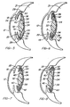
- Figures 9-12 are sections, similar to Figure 3 , through modified accommodating intraocular lenses having alternative optical shapes, wherein Figures 9, 11, and 12 are not embodiments of the invention and wherein Fig.10 is an embodiment of the invention.
- Figure 13 is a section similar to Figure 3 through a modified accommodating intraocular lens illustrating the lens in its normal unstressed configuration.
- Figure 14 is a section similar to Figure 16 , illustrating the lens in its distant vision position.
- Figure 15 is a section through a modified accommodating intraocular lens having an anteriorly displaced optic.
- Figure 16 is an anterior side view of a modified accommodating intraocular lens according to the invention having integral fixation means for fixing the lens in the capsular bag of the eye.
- Figure 17 is a section taken on line 17-17 in Figure 16 .
- Figures 18-21 are anterior side views of modified accommodating intraocular lenses according to the invention having alternative integral fixation means for fixing the lenses in the capsular bag of the eye.
- Figure 22 is an anterior side view of a modified accommodating intraocular lens according to the invention having springs for aiding accommodation.
- Figure 23 illustrates the lens of Figure 22 implanted within the capsular bag of a human eye like that in Figure 1 , and showing the lens in the position which the lens occupies immediately after surgery as well as after a certain degree of accommodation.
- Figure 24 is a view similar to Figure 23 showing the lens in its posterior distant vision position.
- Figures 25-30 are anterior side views of modified accommodating intraocular lenses according to the invention having separate fixation means for fixing the lenses in the capsular bag of a human eye like that in Figure 1 .
- Figures 31-34 illustrate modified accommodating intraocular lenses having integral fixation means, wherein Figures 31 and 32 , are embodiments of the invention and wherein Figures 33 and 34 are not embodiments of the invention.
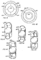
- Figures 35-37 illustrate the capsulotomy produced by a continuous tear circular capsulotomy, (capsulorhexis), a beer can capsulotomy, and an envelope capsulotomy, respectively.
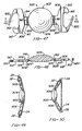
- Figure 38 is an anterior face view of a plate haptic spring lens according to the invention.
- Figure 39 is a view similar to Figure 4 showing the plate haptic spring lens of Figure 38 implanted within the eye.
- Figure 40 is an enlarged section taken on line 40-40 in Figure 39 .
- Figures 41 and 42 illustrate two ways of enlarging the capsulotomy of a capsular bag after completion of fibrosis to allow anterior movement of a relatively large lens optic.
- Figure 43 is an anterior side view of a modified plate haptic lens.
- Figures 44-46 illustrate modified plate haptic spring lenses according to the invention.
- Figure 47 is a plan view of the anterior side of a presently preferred accommodating lens according to the invention.
- Figure 48 is a section taken on line 48-48 in Figure 47 .
- Figure 49 illustrates the lens of Figure 47 implanted within the capsular bag of an eye and shows the lens in its posterior distant vision position.
- Figure 50 is a view similar to Figure 49 showing the lens at or near the forward limit of its accommodation.
- Figure 51 is a section similar to Figure 48 through a modified accommodating lens according to the invention.
- Figure 52 is a view similar to Figure 47 of a further modified accommodating lens according to the invention.
- Figure 53 is a view similar to Figure 47 of yet a further modified accommodating lens according to the invention.
- the natural lens comprises a lens capsule having elastic anterior and posterior walls A and P, respectively, which are referred to by ophthalmologists and herein as anterior and posterior capsules, respectively.
- the natural lens capsule ( Figure 1A ) contains a normally optically clear crystalline lens matrix M. In many individuals, this lens matrix becomes cloudy with advancing age and forms what is called a cataract. It is now common practice to restore a cataract patient's vision by removing the cataract from the natural lens and replacing the lens matrix by an artificial intraocular lens.
- continuous tear circular capsulotomy involves tearing the anterior capsule A along a generally circular tear line in such a way as to form a relatively smooth-edged circular opening in the center of the anterior capsule.
- the cataract is removed from the natural lens capsule through this opening.
- the eye includes an optically clear anterior cornea 12, an opaque sclera 14 on the inner side of which is the retina 16 of the eye, an iris 18, a capsular bag 20 behind the iris, and a vitreous cavity 21 behind the capsular bag filled with the gel-like vitreous humor.
- the capsular bag 20 is the structure of the natural lens of the eye which remains intact within the eye after the continuous tear circular tear capsulorhexis has been performed and the natural lens matrix has been removed from on the natural lens.
- the capsular bag 20 includes an annular anterior capsular remnant or rim 22 and an elastic posterior capsule 24 which are joined along the perimeter of the bag to form an annular crevice-like capsular bag sulcus 25 between rim and posterior capsule.
- the capsular rim 22 is the remnant of the anterior capsule of the natural lens which remains after capsulorhexis has been performed on the natural lens. This rim circumferentially surrounds a central, generally round anterior opening 26 (capsulotomy) in the capsular bag through which the natural lens matrix was previously removed from the natural lens.
- the capsular bag 20 is secured about its perimeter to the ciliary muscle of the eye by zonules 30.
- Natural accommodation in a normal human eye having a normal human crystalline lens involves automatic contraction or constriction and relaxation of the ciliary muscle of the eye by the brain in response to looking at objects at different distances.
- Ciliary muscle relaxation which is the normal state of the muscle, shapes the human crystalline lens for distant vision.
- Ciliary muscle contraction shapes the human crystalline lens for near vision.
- Accommodation The brain-induced change from distant vision to near vision is referred to as accommodation.
- an accommodating intraocular lens 32 which replaces and performs the accommodation function of the removed human crystalline lens.
- Lens 32 is referred to in places as a simple plate haptic lens to distinguish it from the later described plate haptic spring lens of the invention.
- the accommodating intraocular lens may be utilized to replace either a natural lens which is virtually totally defective, such as a cataractous natural lens, or a natural lens that provides satisfactory vision at one distance without the wearing of glasses but provides satisfactory vision at another distance only when glasses are worn.
- the accommodating intraocular lens of the invention can be utilized to correct refractive errors and restore accommodation for persons in their mid-40s who require reading glasses or bifocals for near vision.
- Intraocular lens 32 comprises a body 33 which may be formed of relatively hard material, relatively soft flexible semi-rigid material, or a combination of both hard and soft materials.
- relatively hard materials which are suitable for the lens body are methyl methacrylate, polysulfones, and other relatively hard biologically inert optical materials.
- suitable relatively soft materials for the lens body are silicone, hydrogels, thermolabile materials, and other flexible semi-rigid biologically inert optical materials.
- the lens body 33 has a generally rectangular shape and includes a central optical zone or optic 34 and plate haptics 36 extending from diametrically opposite edges of the optic.
- the haptics have inner ends joined to the optic and opposite outer free ends.
- the haptics 36 are movable anteriorly and posteriorly relative to the optic 34, that is to say the outer ends of the haptics are movable anteriorly and posteriorly relative to the optic.
- the particular lens embodiment illustrated is constructed of a resilient semi-rigid material and has flexible hinges 38 which join the inner ends of the haptics to the optic.
- the haptics are relatively rigid and are flexible about the hinges anteriorly and posteriorly relative to the optic.
- hinges are formed by grooves 40 which enter the anterior side of the lens body and extend along the inner ends of the haptics.
- the haptics 36 are flexible about the hinges 38 in the anterior and posterior directions of the optic.
- the lens has a relatively flat unstressed configuration, illustrated in Figures 2 and 3 , wherein the haptics 36 and their hinges 38 are disposed in a common plane transverse to the optic axis of the optic 34. Deformation of the lens from this unstressed configuration by anterior or posterior deflection of the haptics about their hinges 38 creates in the hinges elastic strain energy forces which bias the lens to its unstressed configuration.
- the lens is constructed of a relatively hard optic material, it may be necessary to replace the flexible hinges 38 by pivotal hinges of some kind. In a later described lens embodiment of the invention, the haptic hinges are eliminated, and the haptics are made flexible throughout their length.
- the accommodating intraocular lens 32 is implanted within the capsular bag 20 of the eye 10 in the position shown in Figures 1 and 5 .
- the ciliary muscle 28 of the eye is maintained in its relaxed state in which the muscle stretches the capsular bag 20 to its maximum diameter.
- the lens is inserted into the bag through the anterior capsule opening 26 and placed in the position shown in Figures 1 and 4 .
- the lens optic 34 is aligned on the axis of the eye with the opening 26, the posterior side of the lens faces the elastic posterior capsule 24 of the bag, and the outer ends of the lens haptics 36 are situated within the sulcus 25 at the radially outer perimeter of the bag.
- the overall length of the lens substantially equals the inner diameter (10-11 mm) of the stretched capsular bag so that the lens fits snugly within the stretched capsular bag with the outer ends of the haptics in contact with the inner perimeter of the bag, as shown. This prevents decentration of the lens and thereby permits the optic 34 to be smaller such that it can move forward inside the capsular rim during the later described accommodation.
- a ciliary muscle relaxant cycloplegic
- a post-operative period of sufficient duration two to three weeks
- the cycloplegic maintains the ciliary muscle 28 in its relaxed state in which the capsular bag 20 is stretched to its maximum diameter and immobilized, and the anterior capsular rim 22 is stretched to a taut trampoline-like condition or position. The rim fibroses from this taut condition.
- the cycloplegic passes through the cornea of the eye into the fluid within the eye and then enters the ciliary muscle from this fluid. While other cycloplegics may be used, atropine is the preferred cycloplegic because of its prolonged paralyzing effect compared to other cycloplegics.
- One drop of atropine for example, may last for two weeks. However, to be on the safe side, patients may be advised to place one drop of atropine in the eye every day during the fibrosis period.
- the capsular rim 22 shrinks during fibrosis and thereby shrinks the capsular bag 20 slightly in its radial direction. This shrinkage combined with shrink wrapping of the lens haptics 36 produces some opposing endwise compression of the lens which tends to buckle or flex the lens at its hinges 38 and thereby move the lens optic 34 along the axis of the eye. Unless restrained, this flexing of the lens might occur either forwardly or rearwardly. The taut anterior capsular rim 22 pushes rearwardly against and thereby prevents forward flexing of the lens. This fibrosis-induced compression of the lens is not sufficient to interfere with proper formation of the haptic pockets in the fibrosed tissue or cause dislocation of the lens.
- Ciliary muscle induced flexing of the lens 32 during fibrosis can be resisted or prevented by placing sutures within the hinge grooves 40. Removal of these sutures after completion of fibrosis may be accomplished by using sutures that are either absorbable in the fluid within the eye or by using sutures made of a material, such as nylon, which can be removed by a laser.
- Natural accommodation in a normal human eye involves shaping of the natural crystalline lens by automatic contraction and relaxation of the ciliary muscle of the eye by the brain to focus the eye at different distances.
- Ciliary muscle relaxation shapes the natural lens for distant vision.
- Ciliary muscle contraction shapes the natural lens for near vision.
- the accommodating intraocular lens 32 is uniquely constructed to utilize this same ciliary muscle action, the fibrosed capsular rim 22, the elastic posterior capsule 24, and the vitreous pressure within the vitreous cavity 21 to effect accommodation movement of the lens optic 34 along the optic axis of the eye between its distant vision position of Figure 6 to its near vision position of Figure 8 .
- the brain relaxes the ciliary muscles 28. Relaxation of the ciliary muscle stretches the capsular bag 20 to its maximum diameter and its fibrosed anterior rim 22 to the taut trampoline-like condition or position discussed above.
- the taut rim deflects the lens rearwardly to its posterior distant vision position of Figure 6 in which the elastic posterior capsule 24 is stretched rearwardly by the lens and thereby exerts a forward bias force on the lens.
- the brain constricts or contracts the ciliary muscle. This ciliary muscle contraction has the three-fold effect of increasing the vitreous cavity pressure, relaxing the capsular bag 20 and particularly its fibrosed capsular rim 22, and exerting opposing endwise compression forces on the ends of the lens haptics 36 with resultant endwise compression of the lens.
- the lens In this intermediate accommodation position, the lens is substantially flat, and the ends of the lens haptics and their hinges 38 are disposed substantially in a common plane normal to the axis of the eye.
- the lens arches rearwardly so that endwise compression of the lens by ciliary muscle contraction produces a rearward buckling force on the lens which resists the initial accommodation.
- the increased vitreous cavity pressure and the forward bias force of the stretched posterior capsule are sufficient to overcome this opposing rearward buckling force and effect forward accommodation movement of the lens to and at least just slightly beyond the intermediate position of Figure 7 .
- the lens haptics 36 flex at their hinges 38 with respect to the lens optic 34 during accommodation. Any elastic strain energy forces developed in the hinges during this flexing produces additional anterior and/or posterior forces on the lens.
- the lens is relatively flat, i.e., that the lens haptics 36 lie in a common plane as shown in Figure 1 , in the normal unstressed state of the lens.
- posterior deflection of the lens from its position of Figure 1 to its distant vision position of Figure 6 creates elastic strain energy forces in the hinges 38 which urge the lens forwardly back to its unstressed position of Figures 1 and thus aid the above discussed initial accommodation of the lens in response to contraction of the ciliary muscle.
- Final accommodation flexing of the lens from its intermediate position of Figure 7 to its near vision position of Figure 8 creates elastic strain energy forces in the hinges 38 which urge the lens rearwardly toward its unstressed position and thus aid initial return of the lens from its near vision position to its distant vision position in response to relaxation of the ciliary muscle.
- the lens may be designed to assume some other normal unstressed position, of course, in which case any elastic strain energy forces created in the lens during flexing of the haptics will aid, resist, or both aid and resist accommodation of the lens to its near vision position and return of the lens to its distant vision position depending upon the unstressed position of the lens.
- the lens haptics 36 slide endwise in their fibrosed tissue pockets 42. As shown best in Figures 2 and 3 , the haptics are tapered endwise in width and thickness to enable the haptics to move freely in the pockets.
- the lens optic 34 moves toward and away from the anterior capsular rim 22.
- the diameter of the optic is made as large as possible to maximize its optical imaging efficiency.
- the optic is preferably but not necessarily made smaller than the diameter of the anterior capsule opening 26 to permit accommodation movement of the optic into and from the opening without interference by the capsular rim 22 in order to maximize the accommodation range.
- the actual lens dimensions are determined by each patient's ocular dimensions.
- a simple plate haptic intraocular lens according to the invention will generally fall within the following ranges: Optic diameter 3.0 mm - 7.0 mm Overall lens length 9.0 mm - 11.5 mm Haptic thickness 0.25 mm - 0.35 mm
- FIG. 10 illustrates an embodiment of the invention.
- the modified lens 50 illustrated in Figure 9 is identical to lens 32 of Figures 1-8 except that the haptic hinges 38 of lens 32 are eliminated in the lens 50, and the haptics 52 of the lens 50 are flexible throughout their length, as illustrated by the broken lines in Figure 9 .
- the modified lens 54 in Figure 10 has an anteriorly arched unstressed shape and includes a bi-convex optic 56, flexible hinges 58, and anteriorly vaulted haptics 60 with convex anterior surfaces 62.
- the convex anterior face 64 of the optic 56 and the convex anterior haptic surfaces 62 are rounded to a common radius.
- the modified intraocular lens 66 in Figure 11 is relatively flat and includes an optic 68 having a planar Fresnel anterior face 70 and a convex posterior face 72, haptics 73, and flexible haptic hinges 74.
- the modified lens 76 in Figure 12 has a posteriorly arched unstressed shape and includes an optic 78 having a planar anterior face 80 and a convex posterior face 82, haptics 84 having convex posterior surfaces 86 and haptic hinges 88, The posterior face 82 of the optic 78 and the posterior surfaces 86 of the haptics 84 are rounded to a common radius.
- the modified lens 90 illustrated in Figures 13 and 14 includes an optic 92 and flexible haptics 94 and has an unstressed near vision configuration shown in Figure 13 .
- the haptics flex to permit posterior deflection of the lens to its distant vision configuration of Figure 14 .
- the optic 92 is posteriorly offset relative to the inner ends of the haptics to permit greater anterior displacement of the optic during accommodation without contacting the anterior capsular rim 22 of the capsular bag 20.
- the modified intraocular lens 100 of Figure 15 includes haptics 102 and an optic 104 which is offset anteriorly relative to the inner ends of the haptics.
- the haptics are joined to diametrically opposite sides of the optic by flexible hinges 106.
- the modified intraocular lenses of Figures 9-15 are implanted within the capsular bag 20 of the eye 10 and utilize the posterior bias of the fibrosed capsular rim 22, the posterior capsule 24, changes in vitreous cavity pressure, and the patient's ciliary muscle action to effect accommodation in the same manner as described in connection with the intraocular lens 32 of Figures 1-8 .
- the outer ends of its haptics 102 are implanted within the capsular bag 20 in essentially the same way as the haptics of lens 32 so that fibrosis of the rim 22 occurs about the haptics in the same manner as described in connection with Figures 1-8 .
- the anteriorly offset optic 104 of the lens 100 protrudes through the anterior opening 26 in the capsular bag 20 and is situated anteriorly of the rim and between the rim and the iris 18 of the eye. There is sufficient space between the rim and the iris to accommodate the optic of a properly sized lens without the optic contacting the iris.
- Figures 16-20 illustrate modified accommodating intraocular lenses according to the invention having means for fixating or anchoring the lens haptics in the capsular bag 20 to prevent the lenses from entering the vitreous cavity 21 of the eye in the event that the posterior capsule 24 becomes torn or a posterior capsulotomy must be performed on the posterior capsule because it becomes hazy.
- the modified intraocular lenses of Figures 16-20 are identical to the lens 32 of Figures 1-8 and are implanted in the capsular bag 20 of the eye 10 in the same manner as described in connection with Figures 1-8 .
- the intraocular lens 110 of Figures 16 and 17 is identical to lens 32 except that the outer ends of the lens haptics 112 have raised shoulders 114.
- Fibrosis of the capsular rim 22 around the haptics 112 and their shoulders 114 anchors or fixates the lens 110 in the capsular bag 20.
- the intraocular lens 116 of Figure 18 is identical to lens 32 except that flexible stalk-like knobs 118 extend diagonally from the outer ends of the lens plate haptics 120.
- the distance between the outer ends of the diametrically opposed knobs 118 is slightly larger than the distance between the outer ends of the lens haptics and slightly larger than the diameter of the capsular bag 20.
- the knobs are set wider than the width of the lens body.
- Fibrosis of the capsular rim 22 around the haptics 120 and their knobs 118 fixes the lens 116 in the capsular bag 20.
- the intraocular lens 122 of Figure 19 is identical to lens 32 except that the outer ends of the lens haptics 124 have openings 126. Fibrosis of the capsular rim 22 occurs around the haptics 124 and through their openings 126 to fixate the lens 122 in the capsular bag 20.
- the intraocular lens 128 of Figure 20 is similar to the lens 122 in that the lens 128 has openings 130 in the outer ends of its haptics 132 through which fibrosis of the capsular rim 22 occurs to fixate the lens in the capsular bag 20.
- the haptic openings 130 are bounded along the outer ends of the haptics by spring loops 134.
- the overall length of the lens 128, measured between the centers of the spring loops 134 is made slightly greater than the maximum diameter of the capsular bag.
- the spring loops 134 press against and are deformed inwardly slightly by the outer circumference of the capsular bag to center the lens in the eye during fibrosis.
- the modified intraocular lens 140 of Figure 21 is identical to the lens 32 of Figures 1-8 except that the lens 140 has centration nipples 142 projecting endwise from the outer ends of the lens haptics 144 to compensate for slight differences, from one patient to another, in the diameter of the human capsular bag 20.
- the diameter of the capsular bag varies from about 11 mm in high myopes to about 9.5 mm in high. hyperopes.
- the centration nipples 142 prevent differences in the degree of flexing of the haptics 144 in capsular bags of different diameters.
- the lens haptics would flex more with marked posterior vaulting of the lens by the fibrosed capsular rim compared to the minimal vaulting of the haptics which would occur in high myopes with relatively large capsular bags.
- the nipples indent themselves into the outer circumference of the capsular bag to compensate for such differing bag diameters and thereby center the lens in the bag.
- the modified intraocular lens 150 illustrated in Figures 22-24 comprises a lens body 152 proper identical to that of Figures 1-8 and springs 154 in the form of U-shaped hoops constructed of biologically inert spring material.
- the ends of these springs are fixed to the anterior sides of the lens haptics 156 adjacent the haptic hinges 158 in such a way that the arched ends of the springs extend a small distance beyond the outer ends of the haptics.
- the springs are stressed to normally lie relatively close to the anterior sides of the haptics.
- the lens body 152 is implanted within the capsular bag 20 of the eye 10 in the same way as described in connection with the lens 32 of Figures 1-8 , and with the outer arched ends of the lens springs 154 lodged within the sulcus 19 of the eye between the iris 18 and the cornea 12.
- the springs 154 lie relatively close to the anterior sides of the lens haptics 156.
- the springs are deflected anteriorly away from the lens haptics, as shown, thereby creating in the springs elastic strain energy forces which aid the stretched posterior capsule 24 and vitreous cavity pressure in displacing the lens anteriorly during accommodation in response to contraction of the ciliary muscle 28.
- Figures 25-32 illustrate modified intraocular lenses according to the invention having a lens body and separate lens fixation elements for positioning the lenses in the capsular bag 20. Fibrosis of the capsular rim 22 occurs around these fixation elements in a manner which securely fixes the elements within the bag.
- the lens body is separable from the fixation elements to permit removal of the lens from and replacement of the lens in its original position in the eye.
- the lens body and fixation elements are secured against separation to prevent entrance of the lens body into the vitreous chamber in the event a tear develops in the posterior capsule 24 of the bag or a posterior capsulotomy is performed in the capsule.
- the modified lens 160 of Figure 25 includes a lens body 162 which is identical, except as noted below, to that of lens 32 in Figures 1-8 and separate fixation elements 164 at the outer ends of the lens haptics 166.
- the fixation elements and haptics are interengaged in such a way that the elements and haptics are capable of relative movement lengthwise of the haptics when the haptics flex during accommodation of the lens.
- the fixation elements 164 in Figure 25 are generally U-shaped loops of biologically inert material having legs 168 which slide within longitudinal sockets 170 entering the outer ends of the haptics 166.
- the haptics 166 are somewhat shorter in length than those of the lens 32, and the overall length of the lens, measured between the outer arched ends of the fixation loops 164, when their legs 168 abut the bottoms of their sockets 170, is less than the maximum diameter of the capsular bag 20 when the ciliary muscle 28 is relaxed and greater than the diameter of the bag when the ciliary muscle is fully contracted for accommodation.
- the lens 160 is implanted within the capsular bag 20 of the eye 10 with the fixation loops 164 and the outer ends of the haptics 166 disposed between the anterior rim 22 and posterior capsule 24 of the capsular bag 20.
- the outer arched ends of the loops are situated at the outer circumference of the bag.
- Fibrosis of the capsular rim 22 occurs around the outer ends of the lens haptics 166 and the exposed outer ends of the fixation loops 164 and through the spaces between the haptics and the loops in such a way that the loops are firmly fixed in the capsular bag, and the haptics form pockets 42 in the fibrose tissue F.
- the posterior bias of the fibrosed capsular rim 22 urges the lens posteriorly to its distant vision position when the ciliary muscle 28 is relaxed, thereby stretching the posterior capsule 24 rearwardly in the same manner as explained in connection with Figures 1-8 .
- the fixation loops have holes 174 in their outer arched ends through which a suture 176 may be passed and tied to retain the loops and lens body in assembled relation during implantation of the lens in the capsular bag. This suture is removed at the conclusion of the surgery. Holes 174 may also be utilized to position the lens in the capsular bag during surgery.
- the lens haptics 166 are separable from and reengageable with the fixation loops 164. This permits the lens body 162 to be removed from the eye any time after surgery for correction or replacement of the lens optic 172 and then replaced in its original position in the eye.
- the modified intraocular lens 180 of Figure 26 is similar to that of Figure 25 except for the following differences.
- the haptics 182 of lens 180 are substantially the same length as the haptics of lens 32 and have cutouts 184 in their outer ends.
- the legs 188 of the fixation loops 186 slide in sockets 190 which enter the bottom edges of the cutouts 184.
- the tongue-like haptic portions at opposite sides of the haptic cutouts 184 and the outer arched ends of the fixation loops 186 are situated within the outer circumference of the bag.
- fibrosis of the capsular rim 22 occurs around the haptics 182 and fixation loops 186 and through the spaces between the haptics and loops so as to firmly fix the loops in the capsular bag and form pockets within which the haptics slide when they flex during accommodation of the lens.
- the legs 188 of the fixation loops 186 and their sockets 190 in the lens haptics 182 are tapered to facilitate free relative movement of the loops and haptics when the haptics flex during accommodation.
- the fixation loops have fixation nipples 192 at their outer arched ends which indent into the outer circumference of the capsular bag 20 to retain the lens against movement relative to the bag during fibrosis.
- Figure 27 illustrates a modified intraocular lens 196 like the lens 180 illustrated in Figure 26 except that the legs 198 of the fixation loops 200 and the haptic sockets 202 which receive these legs have coacting shoulders 204, 206. These shoulders permit limited relative movement of the lens body 208 and loops when the haptics 210 flex during lens accommodation, but secure the lens body and loops against complete separation so as to prevent the lens body from entering the vitreous chamber 21 if a tear occurs or a capsulotomy is performed in the posterior capsule 24.
- Another difference between the lens 196 and the lens 180 resides in the fact that the hinges 212 connecting the inner ends of the haptics 210 to the lens optic 214 extend across only an intermediate portion of the haptic width.
- the remaining lateral portions of the inner haptic ends beyond the ends of the hinges are separated from the optic by arcuate slots 216 centered on the axis of the optic. These separations of the haptics from the optic permit the optic to move freely into and from the anterior opening 26 in the capsular bag 20 without interference with the capsular rim 22 during lens accommodation.
- the generally triangular haptic portions adjacent the slots 216 prevent the rim 22 of the capsular bag 20 from fibrosing between the lens optic 214 and the inner ends of the lens haptics 210 and thereby restricting endwise movement of the haptics in their fibrosed pockets 42.
- the modified lens 220 of Figure 28 includes a lens body 222 and separate fixation elements 224 at the outer ends of the lens haptics 226.
- the inner ends of the haptics are convexly curved and disposed in generally tangential relation to diametrically opposite sides of the lens optic 228 so as to provide relatively large clearance spaces 230 between the optic and the inner haptic ends.
- the haptics and optic are joined along their tangential portions by flexible hinges 232.
- the fixation elements 224 are generally cruciform shaped pins having inner journals 234 which slide within bearing bores 236 entering the bottom edges of cutouts 238 in the outer ends of the haptics 226.
- fixation pins have holes 240 between their ends, outer cross arms 242, and nipples 244 at their outer ends.
- the length of the lens 220 measured between the outer ends of its haptics 226 and fixation pins 224 approximates the maximum inner diameter of the capsular bag 20 when the ciliary muscle is relaxed.
- the fixation pin journals 234 and their bores 236 have coacting shoulders 246, 248 which permit limited relative movement of the lens body and fixation pins when the haptics flex during accommodation but secure the body and fixation pins against complete separation, for the same reasons as explained above in connection with Figure 27 . If desired, the shoulders 246, 248 may be eliminated to permit separation of the fixation pins and lens body for the same reasons as explained in connection with Figure 26 .
- a removable suture may be threaded through the fixation pin holes 240 and tied to hold the fixation pins and lens body in assembled relation during implantation of the lens, as explained in connection with Figure 25 .
- the holes may also be used to position the lens in the capsular bag during implantation of the lens.
- the outer ends of the lens haptics 226 and the fixation pins 224 are disposed between the capsular rim 22 and posterior capsule 24 of the bag in much the same way as described in connection with Figures 25-27 .
- the nipples 244 indent the outer circumference of the bag to fix the lens against rotation circumferentially around the bag and center the lens in the eye during fibrosis of the rim 22. Fibrosis of the capsular rim occurs about the outer ends of the haptics and the fixation pins to firmly fix the pins in the bag and form pockets in the fibrosed tissue receiving the haptics.
- the lens body 222 is urged posteriorly to its distant vision position by the posterior bias of the capsular rim 22 when the ciliary muscle 28 relaxes and anteriorly toward its near vision position during accommodation by the stretched posterior capsule 24 and increase in vitreous cavity pressure when the ciliary muscle contracts, all in essentially the same way as explained earlier in connection with Figures 25-27 .
- contraction of the capsular bag 20 in response to contraction of the ciliary muscle exerts inward forces on the outer ends of the haptics 226 which produce an anterior buckling moment on the lens body 222 that aids lens accommodation by the posterior capsule.
- the cross arms 242 of the fixation pins 224 are enveloped by the fibrosed tissue F during fibrosis of the rim 22 to provide pivots about which the pins can rotate during buckling of the lens body in the course of lens accommodation.
- the spaces 230 between the inner ends of the haptics 226 and the optic 228 accommodate movement of the optic into and from the opening 26 in the capsular bag without interference with the surrounding capsular rim 22.
- the modified intraocular lenses 260, 262 in Figures 29 and 30 are identical to the lenses 180, 196, respectively, in Figures 26 and 27 except that the fixation loops of the latter lenses are replaced, in Figures 29 and 30 , by fixation pins 264, 266 like those in Figure 28 .
- the modified intraocular lenses 270, 272 in Figures 31 and 32 are identical to the lens 32 of Figures 1-8 except that lens 270 has lateral spring arms 274 which extend from the haptic hinges 276 and lens 272 has lateral spring arms 278 which extend from the edges of the lens haptics 280.
- the arms 274, 278 extend laterally from and longitudinally toward the outer ends of the lens haptics in such a way that in their normal unstressed positions, the arms are disposed at acute angles relative to the longitudinal axes of the lenses.
- the arms are sized in length so that when the lenses are implanted within the capsular bag 20 of the eye, the outer ends of the arms press against the outer circumference of the bag and are thereby curled or compressed to the positions illustrated in broken lines.
- the curl or compression in the arms decreases when the capsular bag expands in response to relaxation of the ciliary muscle during distant vision accommodation of the lens and increases when bag contracts in response to contraction of the ciliary muscle during near vision accommodation of the lens.
- Engagement of the arms with the capsular bag circumference acts to center the lenses in the bag in a position wherein the lens optics 282, 284 are coaxially aligned with the anterior bag opening 26. Fibrosis of the capsular rim 22 occurs about the spring arms to fix the lenses within the capsular bag and about the lens haptics to form pockets in which the haptics slide when they flex during accommodation of the lenses.
- projections such as those indicated at 286 in Figure 32 , may preferably be provided in various embodiments of the invention to space the capsulorhexis from the optic when the capsulorhexis constricts from its configuration shown in Figures 5 to 8 .
- This spacing prevents the anterior capsular rim 22, with a relatively small capsular opening 26, from encroaching onto the optic during fibrosis of capsular rim 22.
- projections 286 extend outwardly anteriorly from the plate haptic surface, and are disposed about and spaced from the optic.
- the projections extend outwardly no farther than the outer extent of the optic, typically to a height of about 1 - 1.5 mm.
- the projections may be in the form of continuous arcs (not shown) and may be inclined outwardly relative to the optic.
- the modified accommodating intraocular lens 290 of Figure 33 which is not according to the invention comprises a circular optic 292 and two pairs 294, 296 of curved, flexible haptics 298, 300 extending from opposite edges of the optic. These haptics have the form of relatively slender arms. At the outer ends of the haptics are enlarged knobs 302. The two haptics 298 of each haptic pair 294, 296 extend out from the optic 292 in mutually divergent relation and curve away from one another toward their outer ends, as shown. The four haptics are disposed in symmetrical relation relative to a plane of symmetry containing the axis of the optic and passing midway between the two haptics of each haptic pair.
- the two haptics 298 are located diametrically opposite one another, and the two haptics 300 are located diametrically opposite one another.
- the diametrical distance measured between the outer ends of the diametrically opposed haptics 298, 300 is made slightly greater than the maximum diameter of capsular bag 20.
- the lens 290 is implanted within the bag in much the same manner as the earlier embodiments of the invention and with the outer ends of the lens haptics 298, 300 disposed between the anterior capsular rim 22 and posterior capsule 24 of the bag.
- the outer ends of the haptics press resiliently against the outer circumference of the bag and flex or bend in such a way as to both accommodate bags of different diameter and center the optic 292 behind the anterior capsulotomy in the bag.
- the anterior capsular rim 22 of the bag fibroses about the haptics to fixate the lens in the bag.
- brain initiated relaxation and constriction of the ciliary muscle 28 of the eye is effective to cause accommodation of the lens between near and distant vision positions in essentially the same manner as described earlier.
- the lens buckles and the haptics flex anteriorly and posteriorly relative to the optic 292 in much the same way as described earlier.
- Fibrosis of the capsular rim about the haptic knobs 302 fixates the lens in the capsular bag and against dislocation in the event a tear or capsulotomy is formed in the posterior capsule 24 of the bag.
- the modified accommodating intraocular lens 310 of Figure 34 which is not according to the invention is similar to the lens 290 of Figure 33 and differs from the lens 290 only in the following respects.
- the four haptics 312, 314 of the lens 310 are symmetrically tapered from relatively wide inner ends which are joined to the lens optic 316 to relatively narrow outer ends.
- At the outer ends of the haptics 312, 314 are enlarged knobs 318.
- At inner ends of the haptics are grooves 320 which form flexible hinges 322 about which the haptics are flexible anteriorly and posteriorly of the optic.
- the diametrical distance between the outer ends of the diametrically opposed haptics 312, 314 approximates or slightly exceeds the maximum diameter of the capsular bag 20.
- the lens 310 is implanted within the bag, and fibrosis of the anterior capsular rim 22 of the bag occurs about the lens haptics in the same way as described in connection with lens 290. After fibrosis is complete, brain initiated relaxation and constriction of the ciliary muscle 28 of the eye cause accommodation of the lens in the same manner as described in connection with lens 290. Fibrosis of the capsular rim about the haptic knobs 318 fixates the lens in the capsular bag and against dislocation in the event a tear or capsulotomy is formed in the posterior capsule 24 of the bag.
- the accommodating plate haptic lenses described to this point are referred to herein as simple plate haptic lenses. These lenses are intended for use when the anterior capsulotomy procedure performed on the eye provides an anterior annular capsular remnant or rim that remains intact and circumferentially continuous throughout fibrosis and has a sufficient radial width to retain the lens in the proper position within the capsular bag during and/or after fibrosis.
- this invention provides modified accommodating intraocular lenses, illustrated in Figures 38-40 and 44-46 and referred to as plate haptic spring lenses, for use when the anterior capsular remnant or rim of the capsular bag is ruptured, that is cut or torn, or has too small a radial width to firmly retain the lens in proper position during and/or after fibrosis.
- a ruptured capsular remnant or rim may occur in different ways.
- continuous tear circular capsulotomy, or capsulorhexis ( Figure 35 ) involves tearing the anterior capsule of the natural lens along a circular tear line to form in the anterior capsule a circular opening or capsulotomy 400 circumferentially surrounded by an annular remnant or rim 402 of the anterior capsule. Improper performance of this capsulorhexis can easily create slits or tears 404 in the capsular rim.
- a beer can or can opener capsulotomy involves piercing the anterior capsule of the natural lens at a multiplicity of close positions 404 along a circular line and removing the circular portion of the anterior capsular rim within the pierced line to form an anterior capsule opening 406 circumferentially surrounded by an annular rim 408. While this rim may be initially intact and circumferentially continuous, it has an inner scalloped edge 410 having stress-inducing regions that render the rim very prone to tearing radially, as shown at 411, during surgery or subsequent fibrosis.
- An envelope capsulotomy involves slitting the anterior capsule of the natural lens along a horizontal line 412, then along vertical lines 414 extending upwardly from and intersecting the horizontal slit, and then tearing the anterior capsule along a tear line 416 which arches upwardly from the upper end of the vertical slit and then extends vertically downward to join the second vertical cut.
- This capsulorhexis produces an anterior capsule opening 418 bounded by a capsular remnant 420 which is slit at 412 and hence is inherently ruptured.
- a ruptured anterior capsular remnant or rim may preclude utilization of a simple plate haptic lens of the invention for the following reasons.
- a ruptured rim may not firmly retain the lens haptics in the sulcus of the capsular bag during fibrosis. This renders the lens prone to decentration and/or dislocation, such as dislocation into the vitreous cavity if the posterior capsule tears or becomes cloudy over a period of time and is cut with a laser to provide a capsulotomy in the posterior capsule.
- a ruptured capsular rim may be incapable of assuming the taut trampoline-like condition of an intact capsular rim.
- a ruptured capsular rim may be incapable of effecting full posterior deflection of a plate haptic lens to a distant viewing position against the posterior capsule during and after fibrosis.
- a ruptured capsular rim may also permit anterior deflection of the lens during fibrosis.
- the power of an intraocular lens is selected for each individual patient and may be dependent upon their spectacle power, and since good vision without glasses requires the lens optic to be situated at precisely the correct distance from the retina throughout the range of accommodation, a simple plate haptic lens of the invention may not be acceptable for use with a ruptured anterior capsular remnant or rim.
- FIGs 38-40 illustrate an accommodating plate haptic spring intraocular lens 420 of the invention for use with a ruptured anterior capsular remnant or rim, such as any one of those illustrated in Figures 35-37 .
- This plate haptic spring lens has a lens body 422 proper similar to that of the plate haptic lens 32 in Figures 1-8 and springs 424 at the ends of the body.
- the lens body 422 includes a central optic 426 and flexible plate haptics 428 extending outward from diametrically opposite sides of the optic. These haptics are joined to the optic by hinges 429 formed by grooves in the anterior side of the lens.
- the springs 424 are resilient loops which are staked at one end to the ends of the haptics 428 at opposite sides of the longitudinal centerline of the body. These spring loops bow outwardly lengthwise of the lens body from their staked ends to their centers and then turn back toward the lens body from their centers to their free ends.
- the ends of the haptics 428 have recesses 430 over which the spring loops extend in such a way that the loops and the edges of the recesses form openings 432 therebetween.
- the ends of the spring loops have holes 433 to receive instruments for positioning the lens in the eye.
- the plate haptic spring lens 420 is implanted within the capsular bag 20 of the eye in the same manner as described earlier in connection with the simple plate haptic lenses of the invention. That is to say, the lens 420 is implanted within the eye while its ciliary muscle 28 is paralyzed in its relaxed state, and the capsular bag is thereby stretched to its maximum diameter (9-11 mm).
- the overall length of the lens body 422 measured between the ends of the lens haptics 428 at either side of the haptic recesses 430 substantially equals the inner diameter of the stretched capsular bag.
- the overall length of the lens measured between the outer edges of the spring loops 424 at their centers when the loops are in their normal unstressed state is slightly greater than this inner diameter of the stretched capsular bag.
- the lens body 422 will have an overall length of 10-10.6 mm measured between the outer ends of the lens haptics, and the overall length of the lens measured between the centers of the unstressed spring loops will be in the range of 11-12.5 mm.
- Figures 39 and 40 illustrate the plate haptic spring lens 420 implanted in a capsular bag 20 which is stretched by relaxation of the ciliary muscle 28 and has a torn anterior capsular rim 22 such as might result from an improperly performed continuous tear circular capsulorhexis. Because the rim is torn, the lens body 422 will not fit as snugly in the stretched bag as it would if the capsular rim were an intact rim free of tears. The haptic spring loops 424, however, press outward against the wall of the capsular bag sulcus about the rim of the bag to fixate the lens in the bag during fibrosis following surgery.
- Fibrosis of the torn capsular rim 22 occurs about the outer ends of the plate haptics 428, about the spring loops 424, and through the openings 432 between the loops and the ends of the haptics in such a way as to effect fusion of the torn rim, or more precisely the remnants of the torn rim, to the posterior capsule 24 of the capsular bag.
- the outer ends of the haptics and the spring loops are thereby shrink-wrapped by fibrosis in somewhat the same manner as explained earlier in connection with the simple plate haptic lenses of the invention.
- the torn capsular rim 22 may be incapable of stretching to the taut trampoline condition discussed earlier when the ciliary muscle is relaxed, this shrink-wrapping of the lens during fibrosis of the torn rim will firmly fixate the lens in the capsular bag and should cause some posterior deflection of the lens against the elastic posterior capsule 24. Accordingly, brain-induced constriction and relaxation of the ciliary muscle 28 after fibrosis of the torn capsular rim is complete should effect accommodation of the plate haptic spring lens in much the same way, but possibly not with the same amount of accommodation, as the simple plate haptic lens with an intact non-ruptured capsular rim.
- plate haptic spring lens 420 is designed for use with a ruptured anterior capsular remnant or rim, it can also be utilized with an intact rim.
- a plate haptic spring lens also compensates for improper lens placement in the eye with one end of the lens situated in the capsular bag and the other end of the lens situated in the ciliary sulcus of the eye since the spring loops will expand outwardly to engage both the inner edge of the bag and the wall of the ciliary sulcus.
- an advantage of the plate haptic spring lenses of the invention over the simple plate haptic lenses resides in the fact that the spring lenses eliminate the need to have on hand in the operating room both a simple plate haptic lens for use with an intact capsular rim and a plate haptic spring lens as a backup for the plate haptic lens in the event the rim is ruptured during surgery.
- the haptic spring lens 420 resides in the fact that it permits the lens to have a larger optic than a simple plate haptic lens whose optic diameters will normally be within the range of 4-7 mm.
- the haptic spring lens relies on the spring loops 424 rather than on the capsular remnant or rim 22 to retain the lens in position during fibrosis, the lens may be used with a capsular remnant or rim of smaller radial width and hence larger diameter anterior capsule opening than those required for use of the simple plate haptic accommodating lenses.
- the larger diameter anterior capsule opening permits a larger optic diameter in the range of 7-9 mm which offers certain ophthalmological benefits.
- the large diameter anterior capsule opening necessary to accommodate a large optic spring accommodating lens may be formed during the original surgery by a planned large continuous tear circular capsulorhexis, a beer can capsulotomy of the desired large diameter, a planned envelope capsulotomy or by cutting of radial slits into the anterior capsular rim during surgery after implanting the spring accommodating lens in the capsular bag.
- the invention provides a method whereby the desired large anterior capsule opening may be formed after the original surgery following completion of fibrosis.
- This method involves slitting an annular capsular rim radially with a laser after fibrosis is complete into a number of flap-like remnants 434 ( Figure 41 ) which are easily displaced by the lens during accommodation to permit the lens optic to pass through the anterior capsule opening.
- the anterior capsule opening may be enlarged by cutting the capsular rim with a laser circumferentially along a circular line 436 ( Figure 42 ) concentric with and radially outwardly of the original edge of the opening to enlarge the latter.
- the modified plate haptic spring lens 500 of Figure 43 which is not according to the invention is identical to the lens 420 just described except that the haptics 502 of the modified lens, rather than being hinged to the lens optic 504, are resiliently flexible throughout their length like those of the plate haptic lens in Figure 9 .
- Figure 44 illustrates a further modified plate haptic spring lens 600 according to the invention which is identical to the lens 420 except that the spring loops 602 of the modified lens are formed integrally with the lens haptics 604.
- the modified lens 700 and 800 of Figures 45 and 46 are identical to the lens 600 except that the modified lenses have a pair of spring loops at each end.
- the spring loops 702 of lens 700 have common base portions 704 integrally joined to the ends of the lens haptics 706 along the longitudinal centerline of the lens and free ends which curve outwardly from the base portions both endwise and laterally of the lens.
- the spring loops 802 of lens 800 have base portions 804 integrally joined to the ends of the lens haptics 806 along the longitudinal edges of the haptics and opposite free ends which curve inwardly toward one another laterally of the lens.
- FIGS 47-50 illustrate the presently preferred accommodating intraocular lens of the invention.
- the illustrated lens 900 is a plate haptic spring lens having a body 902 including a round bi-convex optic 904 and plate haptics 906 joined to diametrically opposite sides of the optic by hinge junctions 908.
- Haptics 906 have relatively wide outer end portions 910, inwardly tapered central portions 912, and relatively narrow tapered inner end portions 914.
- the inner end portions 914 are joined to diametrically opposite edge portions of the round optic 904.
- the width of the outer end portions 910 of the haptics measured transverse to the length of the lens approximates the diameter of the optic.
- the width of the inner haptic end portions 914 measured transverse to the length of the lens is substantially less than the diameter of the optic.
- the outer end portions 910 and tapered central portions 912 of the haptics occupy the major length of the haptics measured in the lengthwise direction of the lens.
- the tapered inner end portions 914 of the haptics taper inwardly to a progressively narrower width toward the outer ends of the haptics. These inner end portions effectively form bridges between the optic and the wide outer major portions 910 of the haptics.
- the inner haptic end portions contain V-grooves 916 which extend across the anterior sides of these end portions transverse to the length of the lens close to and preferably in virtually tangential relation to the edge of optic 904.
- the outer end portions 910 of the haptics 906 contain relatively large openings 918 in the form of cutouts which open through the outer ends of the haptics.
- the optic 904 is offset anteriorly relative to the plate haptics 906. That is to say, a plane (median plane) containing the circumferential edge of the lens is offset anteriorly along the lens axis relative to a plane (median plane) passing through the haptics parallel to and midway between their anterior and posterior sides.
- This anterior offset of the optic provides groove-like recesses 924 at the posterior side of the lens along the junctures of the optic and the inner ends 914 of the haptics.
- the relatively thin web-like portions of the lens body between the anterior grooves 916 and posterior recesses 924 are resiliently flexible and form the hinge junctions 908 about which the lens haptics are flexible anteriorly and posteriorly relative to the lens optic.
- the lens 900 is implanted in the capsular bag 20 of a patient's eye, and following completion of fibrosis, undergoes accommodation in response to contraction and relaxation of the ciliary muscle 28 in much the same manner as described in connection with the earlier described lens embodiments of the invention.
- the spring arms 920 of the lens press outwardly against the outer perimeter of the bag to position the lens in the bag even though the anterior remnant 22 of the bag may be slit, torn, or otherwise not intact, in the same manner as described in connection with Figures 38-40 .
- fibrosis occurs around the lens haptics 906 and through the haptic openings 918 to fixate the lens in the capsular bag.
- the ciliary muscle 28 is maintained in its relaxed state until fibrosis is complete by introducing a cycloplegic into the eye, as explained earlier.
- the anterior offset of the optic 904 in the preferred lens 900 provides two advantages.
- One of these advantages resides in the fact that the arrangement of the hinge junctions 908 resulting from the anterior offset of the optic 904 aids anterior buckling of the lens and thereby accommodation movement of the optic relative to the outer ends of the haptics 906 in response to endwise compression of the lens by contraction of the ciliary muscle 28.
- the other advantage resides in the fact that the hinge junctions 908 which join the haptics 906 to the diametrically opposite edge portions of the optic 904 are relatively narrow compared to the diameter of the optic and are preferably narrower than the radius of the bag, as shown. The hinge junctions thus occupy only relatively small circumferential edge portions of the optic.
- the remaining circumferential edge portions of the optic between the junctions are free edge portions which are totally unobstructed by the haptics and taken together constitute a major portion of the optic circumference.
- the diameter of the optic is made to approximate or be slightly smaller than the anterior capsule opening 26 in the capsular bag in which the lens is implanted.
- the actual dimensions of the preferred lens may vary depending upon the patient's ocular dimensions. Following are typical lens dimensions:
- the optic 904 is offset anteriorly relative to the haptics 906 within the thickness of the haptics in such a way that both the circumferential edge of the optic and the hinge junctions 908 are situated within the thickness of the haptics and between their anterior and posterior surfaces.
- Figure 51 is a longitudinal cross-section similar to Figure 48 through a modified intraocular lens 900a of the invention which is identical to lens 900 except that the optic 904a of the lens 900a is offset anteriorly relative to the haptics 906a outside the thickness of the haptics.
- both the circumferential edge of the optic 904a and the hinge junctions 908a between the optic and haptics are located forwardly of the anterior surfaces of the haptics 906a.
- This modified lens configuration provides the same advantages as that of Figures 48-50 .
- the modified accommodating intraocular lens 900b of Figure 52 is essentially identical to the lens 900 except for the following differences. Integrally joined at their ends to and extending across the outer ends of the lens haptics 906b are relatively slender bridges or arches 922b which bound and close the adjacent sides or ends of the haptic openings 918b. These arches are typically 0.20 mm in width and curved to a radius of 5.25 mm about the optical axis of the lens optic 904b. The arches may be either resiliently flexible or relatively flexible or relatively rigid.
- the spring arms 922b of the lens 900b extend laterally across the outer ends of the haptics opposite the open ends or sides of the haptic openings 918b and are flexible endwise of the lens.
- the modified accommodating lens 900c of Figure 53 is similar in many respects to the lens 900b of Figure 52 and differs from the latter lens as follows.
- the spring arms 920b of lens 900b are omitted in the lens 900c.
- the inner end or bridge portions 914c of the lens haptics 906c are quite short in the endwise direction of the lens.
- the length of the inner haptic end portions 914c approximates or is just slightly longer than the width of the open sides of the haptic grooves 916c which form the haptic hinge junctions 908c with the lens optic 904c about which the haptics are flexible anteriorly and posteriorly relative to the optic.
- these hinge junctions occupy or constitute almost the entire length of the inner haptic end portions 914c.
- the haptic end arches 922c may be either resiliently flexible or relatively rigid.
- the lenses 900a, 900b, 900c of Figures 51-53 are implanted in the capsular bag of a patient's eye and provide vision accommodation in response to contraction and relaxation of the ciliary muscle in essentially the same manner as the lens 900 of Figures 47-50 .
- fibrosis occurs through the closed openings 918b, 918c in the lens haptics and about the haptic end arches 922b, 922c to fixate the lenses in the patient's eye.
- the lens 900c may be sized in length between the outer sides of its arches 922c to fit closely in the capsular bag when the ciliary muscle is relaxed, and these arches may be made resiliently flexible to enable the arches to serve as springs which press against the perimeter of the bag to position the lens in the bag in the same manner as the haptic springs of the earlier described plate haptic spring lenses even though the anterior remnant of the bag may be split, torn, or otherwise not an intact remnant.
Abstract
Description
- This invention relates generally to intraocular lenses and more particularly to novel accommodating intraocular lenses for implantation within the capsular bag of a human eye from which the natural lens matrix has been removed by an extraction procedure which leaves intact within the eye the posterior capsule and an anterior capsule remnant of the natural lens. The invention relates also to a novel method of utilizing the intraocular lenses in a human eye to provide the patient with accommodation capability responsive to normal ciliary muscle action.
- The human eye has an anterior chamber between the cornea and the iris, a posterior chamber behind the iris containing a crystalline lens, a vitreous chamber behind the lens containing vitreous humor, and a retina at the rear of the vitreous chamber. The crystalline lens of a normal human eye has a lens capsule attached about its periphery to the ciliary muscle of the eye by zonules and containing a crystalline lens matrix. This lens capsule has elastic optically clear anterior and posterior membrane-like walls commonly referred by ophthalmologists as anterior and posterior capsules, respectively. Between the iris and ciliary muscle is an annular crevice-like space called the ciliary sulcus.
- The human eye possesses natural accommodation capability. Natural accommodation involves relaxation and constriction of the ciliary muscle by the brain to provide the eye with near and distant vision. This ciliary muscle action is automatic and shapes the natural crystalline lens to the appropriate optical configuration for focusing on the retina the light rays entering the eye from the scene being viewed.
- The human eye is subject to a variety of disorders which degrade or totally destroy the ability of the eye to function properly. One of the more common of these disorders involves progressive clouding of the natural crystalline lens matrix resulting in the formation of what is referred to as a cataract. It is now common practice to cure a cataract by surgically removing the cataractous human crystalline lens and implanting an artificial intraocular lens in the eye to replace the natural lens. The prior art is replete with a vast assortment of intraocular lenses for this purpose. Examples of such lenses are described in the following patents:
4,254,509 ,4,298,996 ,4,409,691 ,4,424,597 ,4,573,998 ,4,664,666 ,4,673,406 ,4,738,680 ,4,753,655 ,4,778,463 ,4,813,955 ,4,840,627 ,4,842,601 ,4,963,148 ,4,994,082 ,5,047,051 . - As is evident from the above patents, intraocular lenses differ widely in their physical appearance and arrangement. This invention is concerned with intraocular lenses of the kind having a central optical region or optic and haptics which extend outward from the optic and engage the interior of the eye in such a way as to support the optic on the axis of the eye. My above-listed patent
5,047,051 , which was filed concurrently with my earlier mentioned application Serial No.07/516,636 and is priority document eg forUS patent 5,476,514 , discloses an intraocular lens having a haptic anchor plate, an optic at the longitudinal center of the plate, and resilient haptic loops staked to the ends of the plate. - Up until the late 1980s, cataracts were surgically removed by either intracapsular extraction involving removal of the entire human lens including both its outer lens capsule and its inner crystalline lens matrix, or by extracapsular extraction involving removal of the anterior capsule of the lens and the inner crystalline lens matrix but leaving intact the posterior capsule of the lens. Such intracapsular and extracapsular procedures are prone to certain post-operative complications which introduce undesirable risks into their utilization. Among the most serious of these complications are opacification of the posterior capsule following extracapsular lens extraction, intraocular lens decentration, cystoid macular edema, retinal detachment, and astigmatism.
- An improved surgical procedure called anterior capsulorhexis was developed to alleviate the above and other post-operative complications and risks involved in intracapsular and extracapsular cataract extraction. Simply stated, anterior capsulotomy involves forming an opening in the anterior capsule of the natural lens, leaving intact within the eye a capsular bag having an elastic posterior capsule, an anterior capsular remnant or rim about the anterior capsule opening, and an annular sulcus, referred to herein as a capsular bag sulcus, between the anterior capsule remnant and the outer circumference of the posterior capsule. This capsular bag remains attached about its periphery to the surrounding ciliary muscle of the eye by the zonules of the eye. The cataractous natural lens matrix is extracted from the capsular bag through the anterior capsule opening by phacoemulsification and aspiration or in some other way after which an intraocular lens is implanted within the bag through the opening.
- A relatively recent and improved form of anterior capsulotomy known as capsulorhexis is essentially a continuous tear circular or round capsulotomy. A capsulorhexis is performed by tearing the anterior capsule of the natural lens capsule along a generally circular tear line substantially coaxial with the lens axis and removing the generally circular portion of the anterior capsule surrounded by the tear line. A continuous tear circular capsulorhexis, if performed properly, provides a generally circular opening through the anterior capsule of the natural lens capsule substantially coaxial with the axis of the eye and surrounded circumferentially by a continuous annular remnant or rim of the anterior capsule having a relatively smooth and continuous inner edge bounding the opening. When performing a continuous tear circular capsulorhexis, however, the anterior rim is often accidentally torn or sliced or otherwise ruptured, or the inner rim edge is nicked or sliced in a manner which renders the rim prone to tearing when the rim is stressed, as it is during fibrosis as discussed below.
- Another anterior capsulotomy procedure, referred to as an envelope capsulotomy, involves cutting a horizontal incision in the anterior capsule of the natural lens capsule, then cutting two vertical incisions in the anterior capsule intersecting and rising from the horizontal incision, and finally tearing the anterior capsule along a tear line having an upper upwardly arching portion which starts at the upper extremity of the vertical incision and continues in a downward vertical portion parallel to the vertical incision which extends downwardly and then across the second vertical incision. This procedure produces a generally archway-shaped anterior capsule opening centered on the axis of the eye. The opening is bounded at its bottom by the horizontal incision, at one vertical side by the vertical incision, at its opposite vertical side by the second vertical incision of the anterior capsule, and at its upper side by the upper arching portion of the capsule tear. The vertical incision and the adjacent end of the horizontal incision form a flexible flap at one side of the opening. The vertical tear edge and the adjacent end of the horizontal incision form a second flap at the opposite side of the opening.
- A third capsulotomy procedure, referred to as a beer can or can opener capsulotomy, involves piercing the anterior capsule of the natural lens at a multiplicity of positions along a circular line substantially coaxial with the axis of the eye and then removing the generally circular portion of the capsule circumferentially surrounded by the line. This procedure produces a generally circular anterior capsule opening substantially coaxial with the axis of the eye and bounded circumferentially by an annular remnant or rim of the anterior capsule. The inner edge of this rim has a multiplicity of scallops formed by the edges of the pierced holes in the anterior capsule which render the annular remnant or rim prone to tearing radially when the rim is stressed, as it is during fibrosis as discussed below.
- Intraocular lenses also differ with respect to their accommodation capability, and their placement in the eye. Accommodation is the ability of an intraocular lens to accommodate, that is to focus the eye for near and distant vision. My copending application Serial No.
07/744,472 , which is priority document forWO9303686 - There are four possible placements of an intraocular lens within the eye. These are (a) in the anterior chamber, (b) in the posterior chamber, (c) in the capsular bag, and (d) in the vitreous chamber. The intraocular lens disclosed in my copending application Serial No.
07/744,472 (WO9303686 - According to one of its aspects, this invention provides improved accommodating intraocular lenses to be implanted within the capsular bag of a human eye which remains in the eye after removal of the natural matrix from the human lens capsule through an anterior capsule opening created by an anterior capsulotomy and preferably by a capsulorhexis. An improved accommodating intraocular lens according to the invention has a central optic and haptics which extend outward from diametrically opposite sides of the optic and are movable anteriorly and posteriorly relative to the optic. In some described lens embodiments, the haptics are joined at their inner ends to the optic by hinge-like junctions referred to herein as hinges, and the anterior/posterior movement of the haptics involves pivotal movement of the haptics at these hinges. In some of the described embodiments, the haptics are resiliently flexible, and the anterior/posterior movement of the haptics relative to the optic involves resilient flexing or bending of the haptics. In this regard, it is important to note at the outset that the terms "flex", "flexing", "flexible", and the like are used herein in a broad sense to cover both hinged and resiliently bendable haptics.
- Certain of the described lens embodiments described herein are referred to as simple plate haptic lenses. These simple plate haptic lenses are intended for use when the capsulotomy procedure utilized in the eye surgery is properly performed and provides an anterior capsule remnant or rim that is not only completely intact and free of splits, tears, and the like at the time of lens implantation but is also likely to remain intact during subsequent fibrosis. Other described lens embodiments are referred to as a plate haptic spring lens. These latter lenses are intended for use in those situations in which the capsulotomy produces an anterior capsular remnant which is not intact or which is not likely to remain intact during fibrosis. Both types of lenses are designed for implantation within a capsular bag of the eye in a position wherein the lens optic is aligned on the axis of the eye with the anterior capsule opening in the bag, and the lens haptics are situated within the capsular bag sulcus in contact with the sulcus wall. The normally posterior side of the lens then faces the elastic posterior capsule of the bag.
- The presently preferred lens embodiments of the invention have round optics and haptics joined at their inner ends to opposite edges of the optic by relatively narrow junctions. These junctions occupy only relatively small diametrically opposite edge portions of the optics and leave unobstructed the remaining major circular edge portions of the optic between the junctions. In the preferred lenses described herein, these junctions are hinge junctions about which the haptics are movable anteriorly and posteriorly relative to the optic. These flexible or hinged junctions form a bridge between the optic and the plate haptic which is fixed in position within the anterior and posterior capsules by fibrosis. The bridges are tapered, the widest end being adjacent to the optic. This allows the bridge to slide in and out of the pocket formed by the fibrosed anterior capsular rim and the posterior capsule, and enables the optic to move anteriorly when the plate haptics are subjected to end to end compression.
- During a post-operative healing period on the order of three weeks, active endodermal cells on the posterior side of the anterior capsular rim cause fusion of the rim to the elastic posterior capsule by fibrosis. Fibrosis occurs about the haptics in such a way that the haptics are effectively "shrink-wrapped" by the capsular bag and form radial pockets between the anterior rim and the posterior capsule. These pockets contain the haptics and act to position and center the lens in the eye. The anterior capsular rim shrinks during fibrosis. This shrinkage combined with shrink-wrapping of the haptics causes endwise compression of the lens in a manner which tends to deflect the center of the lens along the axis of the eye relative to the fixated outer haptic ends. The intact fibrosed capsular rim prevents forward deflection of the lens, so that fibrosis-induced deflection of the lens occurs rearwardly to a position in which the lens presses against the elastic posterior capsule and stretches this capsule rearwardly.
- The preferred lens embodiments of the invention have round optics which are sized in diameter to pass through the anterior capsule opening. These preferred lenses are constructed and arranged for anterior accommodation movement of their optics to positions wherein the optics project through the anterior capsule opening to maximize the accommodation range of the lenses.
- According to an important aspect related to the invention, the ciliary muscle is paralyzed in its relaxed state at the start of surgery and is maintained in this relaxed state during both surgery and post-operative fusion of the anterior capsular remnant or rim to the posterior capsule by fibrosis. The ciliary muscle is thus relaxed by introducing a ciliary muscle relaxant (i.e., a cycloplegic) into the eye. While various cycloplegics may be used, the preferred cycloplegic is atropine because of its relatively long effective period compared to other cycloplegics. The cycloplegic is initially introduced into the eye at the start of surgery to dilate the pupil and paralyze the ciliary muscle in its relaxed state. After surgery, cycloplegic drops are periodically introduced into the eye by the patient during a postoperative healing period of sufficient duration (normally about two to three weeks) to maintain the ciliary muscle in its relaxed state until fibrosis is complete. This drug-induced relaxation of the ciliary muscle prevents contraction of the muscle and immobilizes the capsular bag during fibrosis. By this means, the lens is fixed in position within the eye relative to the retina for distance vision. When the cycloplegic effect wears off and the ciliary muscle can contract again, the contraction causes end to end compression on the plates thus moving the optic anteriorly for near vision. If the ciliary muscle was not maintained in its relaxed state, the muscle would undergo essentially normal brain-induced vision accommodation contraction and relaxation during fibrosis. This ciliary muscle action during fibrosis would not only result in improper formation of the haptic pickets in the fibrose tissue, but also ciliary muscle contraction during fibrosis would compress the capsular bag radially and the lens endwise in such a way as to very likely dislocate the lens from its proper position in the bag.
- An accommodating lens according to the invention may have a normal unstressed configuration, such that when deflected from this normal unstressed configuration, the lens develops internal elastic strain energy forces which bias the lens toward its normal unstressed configuration in a manner which aids accommodation. The lens may be generally flat, anteriorly arched, or posteriorly arched in this normal unstressed configuration. One disclosed embodiment of the lens includes auxiliary springs for aiding lens accommodation. Some disclosed lens embodiments have integral fixation means at the haptic ends around which fibrosis of the anterior rim of the capsular bag occurs to fix the lens against dislocation in the eye. Other disclosed embodiments have fixation elements from which the lens proper is separable to permit later removal of the lens for repair or correction and replacement of the lens in its exact original position within the eye.
- As noted earlier, the simple plate haptic lens of the invention is designed for use when the anterior capsulotomy performed on the eye provides an anterior capsular remnant or rim that remains intact and circumferentially continuous throughout fibrosis. The plate haptic spring lenses are designed for use when the anterior capsular remnant or rim of the capsular bag is ruptured, that is cut or torn, or is liable to become so during fibrosis. A ruptured capsular rim may be produced in different ways. For example, improper performance of a continuous tear circular capsulotomy, or capsulorhexis, may result in accidental cutting or tearing of the anterior rim. A beer can or can opener capsulotomy, on the other hand, produces an anterior capsular rim which is not intact and has an inner scalloped edge having stress-inducing regions that render the rim very prone to tearing during surgery or subsequent fibrosis. An envelope capsulotomy inherently produces an anterior capsular remnant which is ruptured and not intact.
- A ruptured anterior capsular remnant or rim may preclude utilization of a simple plate haptic lens of the invention for the following reasons. A ruptured rim may not firmly retain the lens haptics in the sulcus of the capsular bag during fibrosis, thereby rendering the lens prone to decentration and/or posterior or anterior dislocation. A ruptured capsular rim may be incapable of assuming the taut trampoline-like condition of a non-ruptured rim. If so, a ruptured capsular rim is incapable of effecting full posterior deflection of a plate haptic lens to a distant viewing position against the posterior capsule during and after fibrosis. In fact, a ruptured capsular rim may permit anterior deflection of the lens. In either case, since the power of the lens is selected for each individual patient and is dependent upon their spectacle power, and since good vision without glasses requires the lens optic to be at precisely the correct distance from the retina, a simple plate haptic lens of the invention may not be acceptable for use with a ruptured anterior capsular remnant or rim.
- The accommodating plate haptic spring lenses of the invention are designed for use when the anterior capsular remnant or rim of the capsular bag is ruptured. These plate haptic spring lenses are similar to the simple plate haptic lenses but have resilient springs, such as spring loops, at the ends of the plate haptics. When a plate haptic spring lens is implanted in a capsular bag, the haptic springs press outward against the wall of the capsular bag sulcus to fixate the lens in the bag during fibrosis. Fibrosis occurs about the springs in such a way as to effect fusion of the ruptured anterior remnant to the posterior capsule, firm fixation of the springs and hence the haptics in the bag, and posterior deflection of the lenses against the elastic posterior capsule during fibrosis. Brain-induced constriction and relaxation of the ciliary muscle after fibrosis with a ruptured capsular rim effects accommodation of the plate haptic spring lens in much the same way as occurs with the simple plate haptic lens and an intact non-ruptured capsular rim.
- While the plate haptic spring lenses of the invention are designed for use with a ruptured anterior capsular remnant or rim, these lenses can also be utilized with an intact rim. A plate haptic spring lens also compensates for improper lens placement in the eye with one end of the lens situated in the capsular bag and the other end of the lens situated in the ciliary sulcus of the eye. In this regard, an advantage of the plate haptic spring lenses of the invention over the simple plate haptic lenses resides in the fact that the spring lenses eliminate the need to have on hand in the operating room both a simple plate haptic lens for use with an intact capsular rim and a plate haptic spring lens as a substitute for the plate haptic lens in the event the rim is ruptured during surgery.
- Another advantage of the plate haptic spring lenses over the simple plate haptic lenses of the invention resides in the fact that the haptic spring lenses permit an optic of larger diameter than those of simple plate haptic lenses whose optic diameters will normally be restricted to the range of 4-7 mm. Thus, the haptic spring lenses rely on the haptic springs rather than the capsular remnant or rim to retain the lenses in position during fibrosis. As a consequence, these lenses may be used with a capsular remnant or rim of reduced radial width or a capsular rim which is slit or torn, both of which rim types provide an anterior capsule opening of larger effective size than those possible with a simple plate haptic lens. A larger anterior capsule opening, in turn, permits a larger optic diameter which offers certain ophthalmological benefits. According to one aspect of this invention, such a large opening is provided after fibrosis is complete by using a laser to slit the anterior capsular rim radially or cut the rim circumferentially to enlarge the opening.
- The accommodating lens of the invention can be used to provide accommodation in a human eye whose natural lens matrix has been removed from the lens capsule by a procedure involving anterior capsulotomy of the natural lens. The method may be utilized to replace a natural lens from which a cataract has been removed and to correct a refractive error in the eye of a patient who previously wore glasses in order to enable the patient to see well without glasses. For example, the invention can be utilized to correct refractive errors and restore accommodation to persons in their mid-40s who require reading glasses or bifocals for near vision by replacing the clear non-cataractous crystalline lens matrix of their eyes with an accommodating intraocular lens according to the invention. According to the method of utilizing a plate haptic spring lens of the invention, the anterior capsular remnant or rim of the capsular bag is slit radially or cut to enlarge the anterior capsule opening after fibrosis is complete to permit the use of a lens with a relatively large diameter optic larger than 6 or 7 mm.
-
Figure 1 is a section through a human eye from which the natural lens matrix has been removed by a surgical procedure involving anterior capsulotomy, such as capsulorhexis, of the natural lens, and illustrating an accommodating simple plate haptic accommodating lens according to this invention implanted within the capsular bag of the eye. -
Figure 1A is a section through a normal human eye. -
Figure 2 is an anterior side view of the intraocular lens ofFigure 1 . -
Figure 3 is a section taken on line 3-3 inFigure 2 . -
Figure 4 is a section taken on line 4-4 inFigure 1 . -
Figures 5-8 illustrate the manner in which the intraocular lens ofFigures 1-4 is utilized in the eye ofFigure 1 to provide accommodation. -
Figures 9-12 are sections, similar toFigure 3 , through modified accommodating intraocular lenses having alternative optical shapes, whereinFigures 9, 11, and 12 are not embodiments of the invention and whereinFig.10 is an embodiment of the invention. -
Figure 13 is a section similar toFigure 3 through a modified accommodating intraocular lens illustrating the lens in its normal unstressed configuration. -
Figure 14 is a section similar toFigure 16 , illustrating the lens in its distant vision position. -
Figure 15 is a section through a modified accommodating intraocular lens having an anteriorly displaced optic. -
Figure 16 is an anterior side view of a modified accommodating intraocular lens according to the invention having integral fixation means for fixing the lens in the capsular bag of the eye. -
Figure 17 is a section taken on line 17-17 inFigure 16 . -
Figures 18-21 are anterior side views of modified accommodating intraocular lenses according to the invention having alternative integral fixation means for fixing the lenses in the capsular bag of the eye. -
Figure 22 is an anterior side view of a modified accommodating intraocular lens according to the invention having springs for aiding accommodation. -
Figure 23 illustrates the lens ofFigure 22 implanted within the capsular bag of a human eye like that inFigure 1 , and showing the lens in the position which the lens occupies immediately after surgery as well as after a certain degree of accommodation. -
Figure 24 is a view similar toFigure 23 showing the lens in its posterior distant vision position. -
Figures 25-30 are anterior side views of modified accommodating intraocular lenses according to the invention having separate fixation means for fixing the lenses in the capsular bag of a human eye like that inFigure 1 . -
Figures 31-34 illustrate modified accommodating intraocular lenses having integral fixation means, whereinFigures 31 and 32 , are embodiments of the invention and whereinFigures 33 and 34 are not embodiments of the invention. -
Figures 35-37 illustrate the capsulotomy produced by a continuous tear circular capsulotomy, (capsulorhexis), a beer can capsulotomy, and an envelope capsulotomy, respectively. -
Figure 38 is an anterior face view of a plate haptic spring lens according to the invention. -
Figure 39 is a view similar toFigure 4 showing the plate haptic spring lens ofFigure 38 implanted within the eye. -
Figure 40 is an enlarged section taken on line 40-40 inFigure 39 . -
Figures 41 and 42 illustrate two ways of enlarging the capsulotomy of a capsular bag after completion of fibrosis to allow anterior movement of a relatively large lens optic. -
Figure 43 is an anterior side view of a modified plate haptic lens. -
Figures 44-46 illustrate modified plate haptic spring lenses according to the invention. -
Figure 47 is a plan view of the anterior side of a presently preferred accommodating lens according to the invention. -
Figure 48 is a section taken on line 48-48 inFigure 47 . -
Figure 49 illustrates the lens ofFigure 47 implanted within the capsular bag of an eye and shows the lens in its posterior distant vision position. -
Figure 50 is a view similar toFigure 49 showing the lens at or near the forward limit of its accommodation. -
Figure 51 is a section similar toFigure 48 through a modified accommodating lens according to the invention. -
Figure 52 is a view similar toFigure 47 of a further modified accommodating lens according to the invention; and -
Figure 53 is a view similar toFigure 47 of yet a further modified accommodating lens according to the invention. - Turning now to these drawings and first to
Figures 1 and 1A , there is illustrated ahuman eye 10 from which the natural crystalline lens matrix was previously removed by a surgical procedure involving continuous tear circular capsulotomy, or capsulorhexis. The natural lens comprises a lens capsule having elastic anterior and posterior walls A and P, respectively, which are referred to by ophthalmologists and herein as anterior and posterior capsules, respectively. The natural lens capsule (Figure 1A ) contains a normally optically clear crystalline lens matrix M. In many individuals, this lens matrix becomes cloudy with advancing age and forms what is called a cataract. It is now common practice to restore a cataract patient's vision by removing the cataract from the natural lens and replacing the lens matrix by an artificial intraocular lens. - As mentioned earlier, continuous tear circular capsulotomy, or capsulorhexis, involves tearing the anterior capsule A along a generally circular tear line in such a way as to form a relatively smooth-edged circular opening in the center of the anterior capsule. The cataract is removed from the natural lens capsule through this opening. After completion of this surgical procedure, the eye includes an optically clear
anterior cornea 12, anopaque sclera 14 on the inner side of which is the retina 16 of the eye, aniris 18, acapsular bag 20 behind the iris, and avitreous cavity 21 behind the capsular bag filled with the gel-like vitreous humor. Thecapsular bag 20 is the structure of the natural lens of the eye which remains intact within the eye after the continuous tear circular tear capsulorhexis has been performed and the natural lens matrix has been removed from on the natural lens. - The
capsular bag 20 includes an annular anterior capsular remnant orrim 22 and anelastic posterior capsule 24 which are joined along the perimeter of the bag to form an annular crevice-like capsular bag sulcus 25 between rim and posterior capsule. Thecapsular rim 22 is the remnant of the anterior capsule of the natural lens which remains after capsulorhexis has been performed on the natural lens. This rim circumferentially surrounds a central, generally round anterior opening 26 (capsulotomy) in the capsular bag through which the natural lens matrix was previously removed from the natural lens. Thecapsular bag 20 is secured about its perimeter to the ciliary muscle of the eye byzonules 30. - Natural accommodation in a normal human eye having a normal human crystalline lens involves automatic contraction or constriction and relaxation of the ciliary muscle of the eye by the brain in response to looking at objects at different distances. Ciliary muscle relaxation, which is the normal state of the muscle, shapes the human crystalline lens for distant vision. Ciliary muscle contraction shapes the human crystalline lens for near vision. The brain-induced change from distant vision to near vision is referred to as accommodation.
- Implanted within the
capsular bag 20 of theeye 10 is an accommodatingintraocular lens 32 according to this invention which replaces and performs the accommodation function of the removed human crystalline lens.Lens 32 is referred to in places as a simple plate haptic lens to distinguish it from the later described plate haptic spring lens of the invention. As mentioned earlier and will become readily understood as the description proceeds, the accommodating intraocular lens may be utilized to replace either a natural lens which is virtually totally defective, such as a cataractous natural lens, or a natural lens that provides satisfactory vision at one distance without the wearing of glasses but provides satisfactory vision at another distance only when glasses are worn. For example, the accommodating intraocular lens of the invention can be utilized to correct refractive errors and restore accommodation for persons in their mid-40s who require reading glasses or bifocals for near vision. -
Intraocular lens 32 comprises a body 33 which may be formed of relatively hard material, relatively soft flexible semi-rigid material, or a combination of both hard and soft materials. Examples of relatively hard materials which are suitable for the lens body are methyl methacrylate, polysulfones, and other relatively hard biologically inert optical materials. Examples of suitable relatively soft materials for the lens body are silicone, hydrogels, thermolabile materials, and other flexible semi-rigid biologically inert optical materials. - The lens body 33 has a generally rectangular shape and includes a central optical zone or
optic 34 and plate haptics 36 extending from diametrically opposite edges of the optic. The haptics have inner ends joined to the optic and opposite outer free ends. Thehaptics 36 are movable anteriorly and posteriorly relative to the optic 34, that is to say the outer ends of the haptics are movable anteriorly and posteriorly relative to the optic. The particular lens embodiment illustrated is constructed of a resilient semi-rigid material and hasflexible hinges 38 which join the inner ends of the haptics to the optic. The haptics are relatively rigid and are flexible about the hinges anteriorly and posteriorly relative to the optic. These hinges are formed bygrooves 40 which enter the anterior side of the lens body and extend along the inner ends of the haptics. Thehaptics 36 are flexible about thehinges 38 in the anterior and posterior directions of the optic. The lens has a relatively flat unstressed configuration, illustrated inFigures 2 and 3 , wherein thehaptics 36 and theirhinges 38 are disposed in a common plane transverse to the optic axis of the optic 34. Deformation of the lens from this unstressed configuration by anterior or posterior deflection of the haptics about theirhinges 38 creates in the hinges elastic strain energy forces which bias the lens to its unstressed configuration. If the lens is constructed of a relatively hard optic material, it may be necessary to replace the flexible hinges 38 by pivotal hinges of some kind. In a later described lens embodiment of the invention, the haptic hinges are eliminated, and the haptics are made flexible throughout their length. - The accommodating
intraocular lens 32 is implanted within thecapsular bag 20 of theeye 10 in the position shown inFigures 1 and5 . When implanting the lens in the bag, theciliary muscle 28 of the eye is maintained in its relaxed state in which the muscle stretches thecapsular bag 20 to its maximum diameter. The lens is inserted into the bag through theanterior capsule opening 26 and placed in the position shown inFigures 1 and 4 . In this position, thelens optic 34 is aligned on the axis of the eye with theopening 26, the posterior side of the lens faces theelastic posterior capsule 24 of the bag, and the outer ends of thelens haptics 36 are situated within the sulcus 25 at the radially outer perimeter of the bag. The overall length of the lens substantially equals the inner diameter (10-11 mm) of the stretched capsular bag so that the lens fits snugly within the stretched capsular bag with the outer ends of the haptics in contact with the inner perimeter of the bag, as shown. This prevents decentration of the lens and thereby permits the optic 34 to be smaller such that it can move forward inside the capsular rim during the later described accommodation. - During a post-operative healing period on the order of two to three weeks following surgical implantation of the
lens 32 in thecapsular bag 20, epithelial cells under the anterior capsular rim 22 of the bag cause fusion of the rim to theposterior capsule 24 by fibrosis. This fibrosis occurs around the lens haptics 36 in such a way that the haptics are "shrink-wrapped" by thecapsular bag 20, and the haptics form pockets 42 in the fibrosed material F (Figures 4 and6-8 ). These pockets cooperate with the lens haptics to position and center the lens in the eye. In order to insure proper formation of thehaptic pockets 42 and prevent dislocation of the lens by ciliary muscle contraction during fibrosis, sufficient time must be allowed for fibrosis to occur to completion without contraction of theciliary muscle 28 from its relaxed state. According to an important aspect of this invention, this is accomplished by introducing a ciliary muscle relaxant (cycloplegic) into the eye before surgery to dilate the pupil and paralyze the ciliary muscle in its relaxed state and having the patient periodically administer cycloplegic drops into the eye during a post-operative period of sufficient duration (two to three weeks) to permit fibrosis to proceed to completion without contraction of the ciliary muscle. The cycloplegic maintains theciliary muscle 28 in its relaxed state in which thecapsular bag 20 is stretched to its maximum diameter and immobilized, and the anterior capsular rim 22 is stretched to a taut trampoline-like condition or position. The rim fibroses from this taut condition. The cycloplegic passes through the cornea of the eye into the fluid within the eye and then enters the ciliary muscle from this fluid. While other cycloplegics may be used, atropine is the preferred cycloplegic because of its prolonged paralyzing effect compared to other cycloplegics. One drop of atropine, for example, may last for two weeks. However, to be on the safe side, patients may be advised to place one drop of atropine in the eye every day during the fibrosis period. - The
capsular rim 22 shrinks during fibrosis and thereby shrinks thecapsular bag 20 slightly in its radial direction. This shrinkage combined with shrink wrapping of thelens haptics 36 produces some opposing endwise compression of the lens which tends to buckle or flex the lens at itshinges 38 and thereby move thelens optic 34 along the axis of the eye. Unless restrained, this flexing of the lens might occur either forwardly or rearwardly. The taut anteriorcapsular rim 22 pushes rearwardly against and thereby prevents forward flexing of the lens. This fibrosis-induced compression of the lens is not sufficient to interfere with proper formation of the haptic pockets in the fibrosed tissue or cause dislocation of the lens. Accordingly, endwise compression of the lens by fibrosis aided by the rearward thrust of the taut capsular rim against the lens haptics 36 causes rearward flexing of the lens from its initial position ofFigures 1 and5 to its position ofFigure 6 . The lens haptics 36 are made sufficiently rigid that they will not be bent or bowed by the forces of fibrosis. At the conclusion of fibrosis, the lens occupies its posterior position ofFigure 6 wherein the lens presses rearwardly against theelastic posterior capsule 24 and stretches this capsule rearwardly. The posterior capsule then exerts a forward elastic bias force on the lens. This posterior position of the lens is its distant vision position. - Ciliary muscle induced flexing of the
lens 32 during fibrosis can be resisted or prevented by placing sutures within thehinge grooves 40. Removal of these sutures after completion of fibrosis may be accomplished by using sutures that are either absorbable in the fluid within the eye or by using sutures made of a material, such as nylon, which can be removed by a laser. - Natural accommodation in a normal human eye involves shaping of the natural crystalline lens by automatic contraction and relaxation of the ciliary muscle of the eye by the brain to focus the eye at different distances. Ciliary muscle relaxation shapes the natural lens for distant vision. Ciliary muscle contraction shapes the natural lens for near vision.
- The accommodating
intraocular lens 32 is uniquely constructed to utilize this same ciliary muscle action, the fibrosedcapsular rim 22, theelastic posterior capsule 24, and the vitreous pressure within thevitreous cavity 21 to effect accommodation movement of thelens optic 34 along the optic axis of the eye between its distant vision position ofFigure 6 to its near vision position ofFigure 8 . Thus, when looking at a distant scene, the brain relaxes theciliary muscles 28. Relaxation of the ciliary muscle stretches thecapsular bag 20 to its maximum diameter and its fibrosedanterior rim 22 to the taut trampoline-like condition or position discussed above. The taut rim deflects the lens rearwardly to its posterior distant vision position ofFigure 6 in which theelastic posterior capsule 24 is stretched rearwardly by the lens and thereby exerts a forward bias force on the lens. When looking at a near scene, such as a book when reading, the brain constricts or contracts the ciliary muscle. This ciliary muscle contraction has the three-fold effect of increasing the vitreous cavity pressure, relaxing thecapsular bag 20 and particularly its fibrosedcapsular rim 22, and exerting opposing endwise compression forces on the ends of the lens haptics 36 with resultant endwise compression of the lens. Relaxation of the capsular rim permits the rim to flex forwardly and thereby enables the combined forward bias force exerted on the lens by the rearwardly stretched posterior capsule and the increased vitreous cavity pressure to push the lens forwardly in an initial accommodation movement from the position ofFigure 6 to the intermediate accommodation position ofFigure 7 . - In this intermediate accommodation position, the lens is substantially flat, and the ends of the lens haptics and their
hinges 38 are disposed substantially in a common plane normal to the axis of the eye. During the initial accommodation, the lens arches rearwardly so that endwise compression of the lens by ciliary muscle contraction produces a rearward buckling force on the lens which resists the initial accommodation. However, the increased vitreous cavity pressure and the forward bias force of the stretched posterior capsule are sufficient to overcome this opposing rearward buckling force and effect forward accommodation movement of the lens to and at least just slightly beyond the intermediate position ofFigure 7 . At this point, endwise compression of the lens by the contracted ciliary muscle produces a forward buckling force on the lens which effects final accommodation of the lens beyond the intermediate position ofFigure 7 to the near vision position ofFigure 8 . Subsequent brain-induced relaxation of theciliary muscle 28 in response to looking at a distant scene reduces the vitreous cavity pressure, stretches thecapsular bag 20 to its maximum diameter, and restores the anterior capsular rim 22 to its taut trampoline-like condition to effect return of the lens to its distant viewing position ofFigure 6 . During accommodation, thelens optic 34 moves along the axis of the eye toward and away from the retina 16. The power of the optic is selected by the brain to sharply focus incoming light rays on the retina throughout the range of this accommodation movement. - The lens haptics 36 flex at their
hinges 38 with respect to thelens optic 34 during accommodation. Any elastic strain energy forces developed in the hinges during this flexing produces additional anterior and/or posterior forces on the lens. For example, assume that the lens is relatively flat, i.e., that the lens haptics 36 lie in a common plane as shown inFigure 1 , in the normal unstressed state of the lens. In this case, posterior deflection of the lens from its position ofFigure 1 to its distant vision position ofFigure 6 creates elastic strain energy forces in thehinges 38 which urge the lens forwardly back to its unstressed position ofFigures 1 and thus aid the above discussed initial accommodation of the lens in response to contraction of the ciliary muscle. Final accommodation flexing of the lens from its intermediate position ofFigure 7 to its near vision position ofFigure 8 creates elastic strain energy forces in thehinges 38 which urge the lens rearwardly toward its unstressed position and thus aid initial return of the lens from its near vision position to its distant vision position in response to relaxation of the ciliary muscle. The lens may be designed to assume some other normal unstressed position, of course, in which case any elastic strain energy forces created in the lens during flexing of the haptics will aid, resist, or both aid and resist accommodation of the lens to its near vision position and return of the lens to its distant vision position depending upon the unstressed position of the lens. - During accommodation, the lens haptics 36 slide endwise in their fibrosed tissue pockets 42. As shown best in
Figures 2 and 3 , the haptics are tapered endwise in width and thickness to enable the haptics to move freely in the pockets. Thelens optic 34 moves toward and away from the anteriorcapsular rim 22. The diameter of the optic is made as large as possible to maximize its optical imaging efficiency. The optic is preferably but not necessarily made smaller than the diameter of the anterior capsule opening 26 to permit accommodation movement of the optic into and from the opening without interference by thecapsular rim 22 in order to maximize the accommodation range. The actual lens dimensions are determined by each patient's ocular dimensions. The dimensions of a simple plate haptic intraocular lens according to the invention will generally fall within the following ranges:Optic diameter 3.0 mm - 7.0 mm Overall lens length 9.0 mm - 11.5 mm Haptic thickness 0.25 mm - 0.35 mm - Refer now to
Figures 9-15 illustrating several possible alternative shapes of the accommodating intraocular lens wherein onlyFig. 10 illustrates an embodiment of the invention. The modifiedlens 50 illustrated inFigure 9 is identical tolens 32 ofFigures 1-8 except that the haptic hinges 38 oflens 32 are eliminated in thelens 50, and thehaptics 52 of thelens 50 are flexible throughout their length, as illustrated by the broken lines inFigure 9 . The modified lens 54 inFigure 10 has an anteriorly arched unstressed shape and includes abi-convex optic 56, flexible hinges 58, and anteriorly vaulted haptics 60 with convex anterior surfaces 62. The convex anterior face 64 of the optic 56 and the convex anterior haptic surfaces 62 are rounded to a common radius. The modifiedintraocular lens 66 inFigure 11 is relatively flat and includes an optic 68 having a planar Fresnelanterior face 70 and a convex posterior face 72, haptics 73, and flexible haptic hinges 74. The modifiedlens 76 inFigure 12 has a posteriorly arched unstressed shape and includes an optic 78 having a planaranterior face 80 and aconvex posterior face 82, haptics 84 having convex posterior surfaces 86 and haptic hinges 88, The posterior face 82 of the optic 78 and the posterior surfaces 86 of thehaptics 84 are rounded to a common radius. The modifiedlens 90 illustrated inFigures 13 and 14 includes an optic 92 andflexible haptics 94 and has an unstressed near vision configuration shown inFigure 13 . The haptics flex to permit posterior deflection of the lens to its distant vision configuration ofFigure 14 . The optic 92 is posteriorly offset relative to the inner ends of the haptics to permit greater anterior displacement of the optic during accommodation without contacting the anterior capsular rim 22 of thecapsular bag 20. The modifiedintraocular lens 100 ofFigure 15 includeshaptics 102 and an optic 104 which is offset anteriorly relative to the inner ends of the haptics. The haptics are joined to diametrically opposite sides of the optic byflexible hinges 106. - The modified intraocular lenses of
Figures 9-15 are implanted within thecapsular bag 20 of theeye 10 and utilize the posterior bias of the fibrosedcapsular rim 22, theposterior capsule 24, changes in vitreous cavity pressure, and the patient's ciliary muscle action to effect accommodation in the same manner as described in connection with theintraocular lens 32 ofFigures 1-8 . In the case of thelens 100 inFigure 15 , the outer ends of itshaptics 102 are implanted within thecapsular bag 20 in essentially the same way as the haptics oflens 32 so that fibrosis of therim 22 occurs about the haptics in the same manner as described in connection withFigures 1-8 . The anteriorly offsetoptic 104 of thelens 100, on the other hand, protrudes through theanterior opening 26 in thecapsular bag 20 and is situated anteriorly of the rim and between the rim and theiris 18 of the eye. There is sufficient space between the rim and the iris to accommodate the optic of a properly sized lens without the optic contacting the iris. -
Figures 16-20 illustrate modified accommodating intraocular lenses according to the invention having means for fixating or anchoring the lens haptics in thecapsular bag 20 to prevent the lenses from entering thevitreous cavity 21 of the eye in the event that theposterior capsule 24 becomes torn or a posterior capsulotomy must be performed on the posterior capsule because it becomes hazy. Except as noted below, the modified intraocular lenses ofFigures 16-20 are identical to thelens 32 ofFigures 1-8 and are implanted in thecapsular bag 20 of theeye 10 in the same manner as described in connection withFigures 1-8 . Theintraocular lens 110 ofFigures 16 and 17 is identical tolens 32 except that the outer ends of thelens haptics 112 have raisedshoulders 114. Fibrosis of thecapsular rim 22 around thehaptics 112 and theirshoulders 114 anchors or fixates thelens 110 in thecapsular bag 20. Theintraocular lens 116 ofFigure 18 is identical tolens 32 except that flexible stalk-like knobs 118 extend diagonally from the outer ends of thelens plate haptics 120. The distance between the outer ends of the diametricallyopposed knobs 118 is slightly larger than the distance between the outer ends of the lens haptics and slightly larger than the diameter of thecapsular bag 20. The knobs are set wider than the width of the lens body. These two features help to center the intraocular lens within the capsular bag so that the lens optic is centered immediately behind thecircular capsulotomy 26 in the bag. Fibrosis of thecapsular rim 22 around thehaptics 120 and theirknobs 118 fixes thelens 116 in thecapsular bag 20. Theintraocular lens 122 ofFigure 19 is identical tolens 32 except that the outer ends of thelens haptics 124 haveopenings 126. Fibrosis of thecapsular rim 22 occurs around thehaptics 124 and through theiropenings 126 to fixate thelens 122 in thecapsular bag 20. Theintraocular lens 128 ofFigure 20 is similar to thelens 122 in that thelens 128 hasopenings 130 in the outer ends of itshaptics 132 through which fibrosis of thecapsular rim 22 occurs to fixate the lens in thecapsular bag 20. Unlike thelens 122, however, thehaptic openings 130 are bounded along the outer ends of the haptics byspring loops 134. The overall length of thelens 128, measured between the centers of thespring loops 134 is made slightly greater than the maximum diameter of the capsular bag. Thespring loops 134 press against and are deformed inwardly slightly by the outer circumference of the capsular bag to center the lens in the eye during fibrosis. - The modified
intraocular lens 140 ofFigure 21 is identical to thelens 32 ofFigures 1-8 except that thelens 140 has centrationnipples 142 projecting endwise from the outer ends of the lens haptics 144 to compensate for slight differences, from one patient to another, in the diameter of thehuman capsular bag 20. Thus, the diameter of the capsular bag varies from about 11 mm in high myopes to about 9.5 mm in high. hyperopes. The centration nipples 142 prevent differences in the degree of flexing of thehaptics 144 in capsular bags of different diameters. For example, in a hyperopic eye with a small capsular bag, the lens haptics would flex more with marked posterior vaulting of the lens by the fibrosed capsular rim compared to the minimal vaulting of the haptics which would occur in high myopes with relatively large capsular bags. The nipples indent themselves into the outer circumference of the capsular bag to compensate for such differing bag diameters and thereby center the lens in the bag. - The modified
intraocular lens 150 illustrated inFigures 22-24 comprises alens body 152 proper identical to that ofFigures 1-8 and springs 154 in the form of U-shaped hoops constructed of biologically inert spring material. The ends of these springs are fixed to the anterior sides of thelens haptics 156 adjacent the haptic hinges 158 in such a way that the arched ends of the springs extend a small distance beyond the outer ends of the haptics. The springs are stressed to normally lie relatively close to the anterior sides of the haptics. Thelens body 152 is implanted within thecapsular bag 20 of theeye 10 in the same way as described in connection with thelens 32 ofFigures 1-8 , and with the outer arched ends of the lens springs 154 lodged within thesulcus 19 of the eye between theiris 18 and thecornea 12. When the lens is in the position ofFigure 23 which it occupies immediately after surgery as well as after some degree of accommodation, thesprings 154 lie relatively close to the anterior sides of thelens haptics 156. During posterior displacement of the lens to its distant vision position ofFigure 24 by the posterior bias of the fibrosedcapsular rim 22, the springs are deflected anteriorly away from the lens haptics, as shown, thereby creating in the springs elastic strain energy forces which aid the stretchedposterior capsule 24 and vitreous cavity pressure in displacing the lens anteriorly during accommodation in response to contraction of theciliary muscle 28. -
Figures 25-32 illustrate modified intraocular lenses according to the invention having a lens body and separate lens fixation elements for positioning the lenses in thecapsular bag 20. Fibrosis of thecapsular rim 22 occurs around these fixation elements in a manner which securely fixes the elements within the bag. In some figures, the lens body is separable from the fixation elements to permit removal of the lens from and replacement of the lens in its original position in the eye. In other figures, the lens body and fixation elements are secured against separation to prevent entrance of the lens body into the vitreous chamber in the event a tear develops in theposterior capsule 24 of the bag or a posterior capsulotomy is performed in the capsule. - The modified
lens 160 ofFigure 25 includes alens body 162 which is identical, except as noted below, to that oflens 32 inFigures 1-8 andseparate fixation elements 164 at the outer ends of thelens haptics 166. The fixation elements and haptics are interengaged in such a way that the elements and haptics are capable of relative movement lengthwise of the haptics when the haptics flex during accommodation of the lens. Thefixation elements 164 inFigure 25 are generally U-shaped loops of biologically inertmaterial having legs 168 which slide withinlongitudinal sockets 170 entering the outer ends of thehaptics 166. Thehaptics 166 are somewhat shorter in length than those of thelens 32, and the overall length of the lens, measured between the outer arched ends of thefixation loops 164, when theirlegs 168 abut the bottoms of theirsockets 170, is less than the maximum diameter of thecapsular bag 20 when theciliary muscle 28 is relaxed and greater than the diameter of the bag when the ciliary muscle is fully contracted for accommodation. Thelens 160 is implanted within thecapsular bag 20 of theeye 10 with thefixation loops 164 and the outer ends of thehaptics 166 disposed between theanterior rim 22 andposterior capsule 24 of thecapsular bag 20. The outer arched ends of the loops are situated at the outer circumference of the bag. - Fibrosis of the
capsular rim 22 occurs around the outer ends of thelens haptics 166 and the exposed outer ends of thefixation loops 164 and through the spaces between the haptics and the loops in such a way that the loops are firmly fixed in the capsular bag, and the haptics form pockets 42 in the fibrose tissue F. The posterior bias of the fibrosed capsular rim 22 urges the lens posteriorly to its distant vision position when theciliary muscle 28 is relaxed, thereby stretching theposterior capsule 24 rearwardly in the same manner as explained in connection withFigures 1-8 . When the ciliary muscle contracts during accommodation, the vitreous cavity pressure increases and thecapsular rim 22 relaxes, thereby permitting the stretched posterior capsule and the vitreous cavity pressure to push thelens body 162 forwardly toward its near vision position, again in the same manner as explained in connection withFigures 1-8 . Contraction of the capsular bag in response to contraction of the ciliary muscle during accommodation displacement exerts inward forces on thefixation loops 164. These inward forces urge the loops inwardly in theirhaptic sockets 170 until the loops abut the bottoms of the sockets. The inward forces exerted on the loops then produce an anterior buckling moment on thelens body 162 which aids accommodation of the lens by the posterior capsule. During this accommodation, thelens haptics 166 flex posteriorly relative to thelens optic 172 and slide inwardly in theirfibrose pockets 42 and along thelegs 168 of thefixation loops 164, the movement being aided by hinges 38. - The fixation loops have
holes 174 in their outer arched ends through which asuture 176 may be passed and tied to retain the loops and lens body in assembled relation during implantation of the lens in the capsular bag. This suture is removed at the conclusion of the surgery.Holes 174 may also be utilized to position the lens in the capsular bag during surgery. The lens haptics 166 are separable from and reengageable with thefixation loops 164. This permits thelens body 162 to be removed from the eye any time after surgery for correction or replacement of thelens optic 172 and then replaced in its original position in the eye. - The modified
intraocular lens 180 ofFigure 26 is similar to that ofFigure 25 except for the following differences. First, thehaptics 182 oflens 180 are substantially the same length as the haptics oflens 32 and havecutouts 184 in their outer ends. Thelegs 188 of thefixation loops 186 slide insockets 190 which enter the bottom edges of thecutouts 184. When the lens is implanted within thecapsular bag 20, the tongue-like haptic portions at opposite sides of thehaptic cutouts 184 and the outer arched ends of thefixation loops 186 are situated within the outer circumference of the bag. As with the lens ofFigure 25 , fibrosis of thecapsular rim 22 occurs around thehaptics 182 andfixation loops 186 and through the spaces between the haptics and loops so as to firmly fix the loops in the capsular bag and form pockets within which the haptics slide when they flex during accommodation of the lens. Secondly, thelegs 188 of thefixation loops 186 and theirsockets 190 in thelens haptics 182 are tapered to facilitate free relative movement of the loops and haptics when the haptics flex during accommodation. Thirdly, the fixation loops havefixation nipples 192 at their outer arched ends which indent into the outer circumference of thecapsular bag 20 to retain the lens against movement relative to the bag during fibrosis. -
Figure 27 illustrates a modifiedintraocular lens 196 like thelens 180 illustrated inFigure 26 except that thelegs 198 of thefixation loops 200 and thehaptic sockets 202 which receive these legs have coactingshoulders haptics 210 flex during lens accommodation, but secure the lens body and loops against complete separation so as to prevent the lens body from entering thevitreous chamber 21 if a tear occurs or a capsulotomy is performed in theposterior capsule 24. Another difference between thelens 196 and thelens 180 resides in the fact that the hinges 212 connecting the inner ends of thehaptics 210 to the lens optic 214 extend across only an intermediate portion of the haptic width. The remaining lateral portions of the inner haptic ends beyond the ends of the hinges are separated from the optic byarcuate slots 216 centered on the axis of the optic. These separations of the haptics from the optic permit the optic to move freely into and from theanterior opening 26 in thecapsular bag 20 without interference with thecapsular rim 22 during lens accommodation. The generally triangular haptic portions adjacent theslots 216 prevent therim 22 of thecapsular bag 20 from fibrosing between the lens optic 214 and the inner ends of thelens haptics 210 and thereby restricting endwise movement of the haptics in their fibrosed pockets 42. - The modified
lens 220 ofFigure 28 includes alens body 222 andseparate fixation elements 224 at the outer ends of thelens haptics 226. The inner ends of the haptics are convexly curved and disposed in generally tangential relation to diametrically opposite sides of thelens optic 228 so as to provide relativelylarge clearance spaces 230 between the optic and the inner haptic ends. The haptics and optic are joined along their tangential portions byflexible hinges 232. Thefixation elements 224 are generally cruciform shaped pins havinginner journals 234 which slide within bearing bores 236 entering the bottom edges ofcutouts 238 in the outer ends of thehaptics 226. These fixation pins haveholes 240 between their ends, outercross arms 242, andnipples 244 at their outer ends. The length of thelens 220 measured between the outer ends of itshaptics 226 and fixation pins 224 approximates the maximum inner diameter of thecapsular bag 20 when the ciliary muscle is relaxed. Thefixation pin journals 234 and theirbores 236 have coactingshoulders Figure 27 . If desired, theshoulders Figure 26 . If the shoulders are eliminated, a removable suture may be threaded through the fixation pin holes 240 and tied to hold the fixation pins and lens body in assembled relation during implantation of the lens, as explained in connection withFigure 25 . The holes may also be used to position the lens in the capsular bag during implantation of the lens. - When the
lens 220 is implanted within thecapsular bag 20 of theeye 10, the outer ends of thelens haptics 226 and the fixation pins 224 are disposed between thecapsular rim 22 andposterior capsule 24 of the bag in much the same way as described in connection withFigures 25-27 . Thenipples 244 indent the outer circumference of the bag to fix the lens against rotation circumferentially around the bag and center the lens in the eye during fibrosis of therim 22. Fibrosis of the capsular rim occurs about the outer ends of the haptics and the fixation pins to firmly fix the pins in the bag and form pockets in the fibrosed tissue receiving the haptics. Thelens body 222 is urged posteriorly to its distant vision position by the posterior bias of thecapsular rim 22 when theciliary muscle 28 relaxes and anteriorly toward its near vision position during accommodation by the stretchedposterior capsule 24 and increase in vitreous cavity pressure when the ciliary muscle contracts, all in essentially the same way as explained earlier in connection withFigures 25-27 . During anterior accommodation of the lens, contraction of thecapsular bag 20 in response to contraction of the ciliary muscle exerts inward forces on the outer ends of thehaptics 226 which produce an anterior buckling moment on thelens body 222 that aids lens accommodation by the posterior capsule. Thecross arms 242 of the fixation pins 224 are enveloped by the fibrosed tissue F during fibrosis of therim 22 to provide pivots about which the pins can rotate during buckling of the lens body in the course of lens accommodation. Thespaces 230 between the inner ends of thehaptics 226 and the optic 228 accommodate movement of the optic into and from theopening 26 in the capsular bag without interference with the surroundingcapsular rim 22. - The modified
intraocular lenses Figures 29 and 30 are identical to thelenses Figures 26 and 27 except that the fixation loops of the latter lenses are replaced, inFigures 29 and 30 , byfixation pins Figure 28 . - The modified
intraocular lenses Figures 31 and 32 are identical to thelens 32 ofFigures 1-8 except thatlens 270 haslateral spring arms 274 which extend from the haptic hinges 276 andlens 272 haslateral spring arms 278 which extend from the edges of thelens haptics 280. Thearms capsular bag 20 of the eye, the outer ends of the arms press against the outer circumference of the bag and are thereby curled or compressed to the positions illustrated in broken lines. The curl or compression in the arms decreases when the capsular bag expands in response to relaxation of the ciliary muscle during distant vision accommodation of the lens and increases when bag contracts in response to contraction of the ciliary muscle during near vision accommodation of the lens. Engagement of the arms with the capsular bag circumference acts to center the lenses in the bag in a position wherein thelens optics anterior bag opening 26. Fibrosis of thecapsular rim 22 occurs about the spring arms to fix the lenses within the capsular bag and about the lens haptics to form pockets in which the haptics slide when they flex during accommodation of the lenses. - Referring to
Figure 32 and toFigures 4 to 8 , projections such as those indicated at 286 inFigure 32 , may preferably be provided in various embodiments of the invention to space the capsulorhexis from the optic when the capsulorhexis constricts from its configuration shown inFigures 5 to 8 . This spacing prevents the anteriorcapsular rim 22, with a relatively smallcapsular opening 26, from encroaching onto the optic during fibrosis ofcapsular rim 22. As shown inFigure 32 ,such projections 286 extend outwardly anteriorly from the plate haptic surface, and are disposed about and spaced from the optic. The projections extend outwardly no farther than the outer extent of the optic, typically to a height of about 1 - 1.5 mm. The projections may be in the form of continuous arcs (not shown) and may be inclined outwardly relative to the optic. - The modified accommodating
intraocular lens 290 ofFigure 33 which is not according to the invention comprises acircular optic 292 and two pairs 294, 296 of curved,flexible haptics enlarged knobs 302. The twohaptics 298 of each haptic pair 294, 296 extend out from the optic 292 in mutually divergent relation and curve away from one another toward their outer ends, as shown. The four haptics are disposed in symmetrical relation relative to a plane of symmetry containing the axis of the optic and passing midway between the two haptics of each haptic pair. The twohaptics 298 are located diametrically opposite one another, and the twohaptics 300 are located diametrically opposite one another. The diametrical distance measured between the outer ends of the diametricallyopposed haptics capsular bag 20. Thelens 290 is implanted within the bag in much the same manner as the earlier embodiments of the invention and with the outer ends of thelens haptics capsular rim 22 andposterior capsule 24 of the bag. The outer ends of the haptics press resiliently against the outer circumference of the bag and flex or bend in such a way as to both accommodate bags of different diameter and center the optic 292 behind the anterior capsulotomy in the bag. The anterior capsular rim 22 of the bag fibroses about the haptics to fixate the lens in the bag. After fibrosis is complete, brain initiated relaxation and constriction of theciliary muscle 28 of the eye is effective to cause accommodation of the lens between near and distant vision positions in essentially the same manner as described earlier. During this accommodation, the lens buckles and the haptics flex anteriorly and posteriorly relative to the optic 292 in much the same way as described earlier. Fibrosis of the capsular rim about thehaptic knobs 302 fixates the lens in the capsular bag and against dislocation in the event a tear or capsulotomy is formed in theposterior capsule 24 of the bag. - The modified accommodating
intraocular lens 310 ofFigure 34 which is not according to the invention is similar to thelens 290 ofFigure 33 and differs from thelens 290 only in the following respects. The fourhaptics lens 310, rather than being slender curved arms like those oflens 290, are symmetrically tapered from relatively wide inner ends which are joined to thelens optic 316 to relatively narrow outer ends. At the outer ends of thehaptics enlarged knobs 318. At inner ends of the haptics aregrooves 320 which formflexible hinges 322 about which the haptics are flexible anteriorly and posteriorly of the optic. The diametrical distance between the outer ends of the diametricallyopposed haptics capsular bag 20. Thelens 310 is implanted within the bag, and fibrosis of the anterior capsular rim 22 of the bag occurs about the lens haptics in the same way as described in connection withlens 290. After fibrosis is complete, brain initiated relaxation and constriction of theciliary muscle 28 of the eye cause accommodation of the lens in the same manner as described in connection withlens 290. Fibrosis of the capsular rim about thehaptic knobs 318 fixates the lens in the capsular bag and against dislocation in the event a tear or capsulotomy is formed in theposterior capsule 24 of the bag. - The accommodating plate haptic lenses described to this point are referred to herein as simple plate haptic lenses. These lenses are intended for use when the anterior capsulotomy procedure performed on the eye provides an anterior annular capsular remnant or rim that remains intact and circumferentially continuous throughout fibrosis and has a sufficient radial width to retain the lens in the proper position within the capsular bag during and/or after fibrosis. According to another of its aspects, this invention provides modified accommodating intraocular lenses, illustrated in
Figures 38-40 and44-46 and referred to as plate haptic spring lenses, for use when the anterior capsular remnant or rim of the capsular bag is ruptured, that is cut or torn, or has too small a radial width to firmly retain the lens in proper position during and/or after fibrosis. - As noted earlier, a ruptured capsular remnant or rim may occur in different ways. For example, continuous tear circular capsulotomy, or capsulorhexis, (
Figure 35 ) involves tearing the anterior capsule of the natural lens along a circular tear line to form in the anterior capsule a circular opening orcapsulotomy 400 circumferentially surrounded by an annular remnant or rim 402 of the anterior capsule. Improper performance of this capsulorhexis can easily create slits ortears 404 in the capsular rim. A beer can or can opener capsulotomy (Figure 36 ) involves piercing the anterior capsule of the natural lens at a multiplicity ofclose positions 404 along a circular line and removing the circular portion of the anterior capsular rim within the pierced line to form an anterior capsule opening 406 circumferentially surrounded by anannular rim 408. While this rim may be initially intact and circumferentially continuous, it has an innerscalloped edge 410 having stress-inducing regions that render the rim very prone to tearing radially, as shown at 411, during surgery or subsequent fibrosis. An envelope capsulotomy (Figure 37 ) involves slitting the anterior capsule of the natural lens along ahorizontal line 412, then alongvertical lines 414 extending upwardly from and intersecting the horizontal slit, and then tearing the anterior capsule along atear line 416 which arches upwardly from the upper end of the vertical slit and then extends vertically downward to join the second vertical cut. This capsulorhexis produces an anterior capsule opening 418 bounded by a capsular remnant 420 which is slit at 412 and hence is inherently ruptured. - A ruptured anterior capsular remnant or rim may preclude utilization of a simple plate haptic lens of the invention for the following reasons. A ruptured rim may not firmly retain the lens haptics in the sulcus of the capsular bag during fibrosis. This renders the lens prone to decentration and/or dislocation, such as dislocation into the vitreous cavity if the posterior capsule tears or becomes cloudy over a period of time and is cut with a laser to provide a capsulotomy in the posterior capsule. A ruptured capsular rim may be incapable of assuming the taut trampoline-like condition of an intact capsular rim. As a consequence, a ruptured capsular rim may be incapable of effecting full posterior deflection of a plate haptic lens to a distant viewing position against the posterior capsule during and after fibrosis. A ruptured capsular rim may also permit anterior deflection of the lens during fibrosis. In either case, since the power of an intraocular lens is selected for each individual patient and may be dependent upon their spectacle power, and since good vision without glasses requires the lens optic to be situated at precisely the correct distance from the retina throughout the range of accommodation, a simple plate haptic lens of the invention may not be acceptable for use with a ruptured anterior capsular remnant or rim.
-
Figures 38-40 illustrate an accommodating plate hapticspring intraocular lens 420 of the invention for use with a ruptured anterior capsular remnant or rim, such as any one of those illustrated inFigures 35-37 . This plate haptic spring lens has alens body 422 proper similar to that of the platehaptic lens 32 inFigures 1-8 and springs 424 at the ends of the body. Thelens body 422 includes acentral optic 426 andflexible plate haptics 428 extending outward from diametrically opposite sides of the optic. These haptics are joined to the optic byhinges 429 formed by grooves in the anterior side of the lens. Thesprings 424 are resilient loops which are staked at one end to the ends of thehaptics 428 at opposite sides of the longitudinal centerline of the body. These spring loops bow outwardly lengthwise of the lens body from their staked ends to their centers and then turn back toward the lens body from their centers to their free ends. The ends of thehaptics 428 haverecesses 430 over which the spring loops extend in such a way that the loops and the edges of the recesses formopenings 432 therebetween. The ends of the spring loops haveholes 433 to receive instruments for positioning the lens in the eye. - The plate
haptic spring lens 420 is implanted within thecapsular bag 20 of the eye in the same manner as described earlier in connection with the simple plate haptic lenses of the invention. That is to say, thelens 420 is implanted within the eye while itsciliary muscle 28 is paralyzed in its relaxed state, and the capsular bag is thereby stretched to its maximum diameter (9-11 mm). The overall length of thelens body 422 measured between the ends of thelens haptics 428 at either side of thehaptic recesses 430 substantially equals the inner diameter of the stretched capsular bag. The overall length of the lens measured between the outer edges of thespring loops 424 at their centers when the loops are in their normal unstressed state is slightly greater than this inner diameter of the stretched capsular bag. For example, if the inner diameter of the stretched capsular bag is in the range 10-10.6 mm, thelens body 422 will have an overall length of 10-10.6 mm measured between the outer ends of the lens haptics, and the overall length of the lens measured between the centers of the unstressed spring loops will be in the range of 11-12.5 mm. -
Figures 39 and 40 illustrate the platehaptic spring lens 420 implanted in acapsular bag 20 which is stretched by relaxation of theciliary muscle 28 and has a torn anterior capsular rim 22 such as might result from an improperly performed continuous tear circular capsulorhexis. Because the rim is torn, thelens body 422 will not fit as snugly in the stretched bag as it would if the capsular rim were an intact rim free of tears. Thehaptic spring loops 424, however, press outward against the wall of the capsular bag sulcus about the rim of the bag to fixate the lens in the bag during fibrosis following surgery. Fibrosis of the torn capsular rim 22 occurs about the outer ends of theplate haptics 428, about thespring loops 424, and through theopenings 432 between the loops and the ends of the haptics in such a way as to effect fusion of the torn rim, or more precisely the remnants of the torn rim, to theposterior capsule 24 of the capsular bag. The outer ends of the haptics and the spring loops are thereby shrink-wrapped by fibrosis in somewhat the same manner as explained earlier in connection with the simple plate haptic lenses of the invention. Even though the torn capsular rim 22 may be incapable of stretching to the taut trampoline condition discussed earlier when the ciliary muscle is relaxed, this shrink-wrapping of the lens during fibrosis of the torn rim will firmly fixate the lens in the capsular bag and should cause some posterior deflection of the lens against theelastic posterior capsule 24. Accordingly, brain-induced constriction and relaxation of theciliary muscle 28 after fibrosis of the torn capsular rim is complete should effect accommodation of the plate haptic spring lens in much the same way, but possibly not with the same amount of accommodation, as the simple plate haptic lens with an intact non-ruptured capsular rim. - While the plate
haptic spring lens 420 is designed for use with a ruptured anterior capsular remnant or rim, it can also be utilized with an intact rim. A plate haptic spring lens also compensates for improper lens placement in the eye with one end of the lens situated in the capsular bag and the other end of the lens situated in the ciliary sulcus of the eye since the spring loops will expand outwardly to engage both the inner edge of the bag and the wall of the ciliary sulcus. In this regard, an advantage of the plate haptic spring lenses of the invention over the simple plate haptic lenses resides in the fact that the spring lenses eliminate the need to have on hand in the operating room both a simple plate haptic lens for use with an intact capsular rim and a plate haptic spring lens as a backup for the plate haptic lens in the event the rim is ruptured during surgery. - Another advantage of the
haptic spring lens 420 resides in the fact that it permits the lens to have a larger optic than a simple plate haptic lens whose optic diameters will normally be within the range of 4-7 mm. Thus, since the haptic spring lens relies on thespring loops 424 rather than on the capsular remnant or rim 22 to retain the lens in position during fibrosis, the lens may be used with a capsular remnant or rim of smaller radial width and hence larger diameter anterior capsule opening than those required for use of the simple plate haptic accommodating lenses. The larger diameter anterior capsule opening, of course, permits a larger optic diameter in the range of 7-9 mm which offers certain ophthalmological benefits. - The large diameter anterior capsule opening necessary to accommodate a large optic spring accommodating lens may be formed during the original surgery by a planned large continuous tear circular capsulorhexis, a beer can capsulotomy of the desired large diameter, a planned envelope capsulotomy or by cutting of radial slits into the anterior capsular rim during surgery after implanting the spring accommodating lens in the capsular bag. According to another of its aspects, the invention provides a method whereby the desired large anterior capsule opening may be formed after the original surgery following completion of fibrosis. This method involves slitting an annular capsular rim radially with a laser after fibrosis is complete into a number of flap-like remnants 434 (
Figure 41 ) which are easily displaced by the lens during accommodation to permit the lens optic to pass through the anterior capsule opening. Alternatively, the anterior capsule opening may be enlarged by cutting the capsular rim with a laser circumferentially along a circular line 436 (Figure 42 ) concentric with and radially outwardly of the original edge of the opening to enlarge the latter. - The modified plate
haptic spring lens 500 ofFigure 43 which is not according to the invention is identical to thelens 420 just described except that thehaptics 502 of the modified lens, rather than being hinged to thelens optic 504, are resiliently flexible throughout their length like those of the plate haptic lens inFigure 9 .Figure 44 illustrates a further modified platehaptic spring lens 600 according to the invention which is identical to thelens 420 except that thespring loops 602 of the modified lens are formed integrally with thelens haptics 604. The modifiedlens 700 and 800 ofFigures 45 and 46 are identical to thelens 600 except that the modified lenses have a pair of spring loops at each end. Thespring loops 702 of lens 700 have common base portions 704 integrally joined to the ends of thelens haptics 706 along the longitudinal centerline of the lens and free ends which curve outwardly from the base portions both endwise and laterally of the lens. Thespring loops 802 oflens 800 havebase portions 804 integrally joined to the ends of thelens haptics 806 along the longitudinal edges of the haptics and opposite free ends which curve inwardly toward one another laterally of the lens. -
Figures 47-50 illustrate the presently preferred accommodating intraocular lens of the invention. The illustratedlens 900 is a plate haptic spring lens having abody 902 including a roundbi-convex optic 904 and plate haptics 906 joined to diametrically opposite sides of the optic byhinge junctions 908. -
Haptics 906 have relatively wideouter end portions 910, inwardly taperedcentral portions 912, and relatively narrow taperedinner end portions 914. Theinner end portions 914 are joined to diametrically opposite edge portions of theround optic 904. The width of theouter end portions 910 of the haptics measured transverse to the length of the lens approximates the diameter of the optic. The width of the innerhaptic end portions 914 measured transverse to the length of the lens is substantially less than the diameter of the optic. Theouter end portions 910 and taperedcentral portions 912 of the haptics occupy the major length of the haptics measured in the lengthwise direction of the lens. The taperedinner end portions 914 of the haptics taper inwardly to a progressively narrower width toward the outer ends of the haptics. These inner end portions effectively form bridges between the optic and the wide outermajor portions 910 of the haptics. The inner haptic end portions contain V-grooves 916 which extend across the anterior sides of these end portions transverse to the length of the lens close to and preferably in virtually tangential relation to the edge ofoptic 904. - The
outer end portions 910 of thehaptics 906 contain relativelylarge openings 918 in the form of cutouts which open through the outer ends of the haptics. Joined at one end to the outer ends of the haptics, at one side of the open ends of thehaptic cutouts 918, arespring arms 920. These arms extend laterally across the outer haptic ends and are resiliently flexible endwise of the lens. - As shown in
Figure 48 , the optic 904 is offset anteriorly relative to theplate haptics 906. That is to say, a plane (median plane) containing the circumferential edge of the lens is offset anteriorly along the lens axis relative to a plane (median plane) passing through the haptics parallel to and midway between their anterior and posterior sides. This anterior offset of the optic provides groove-like recesses 924 at the posterior side of the lens along the junctures of the optic and the inner ends 914 of the haptics. The relatively thin web-like portions of the lens body between theanterior grooves 916 andposterior recesses 924 are resiliently flexible and form thehinge junctions 908 about which the lens haptics are flexible anteriorly and posteriorly relative to the lens optic. - Referring to
Figure 49 , thelens 900 is implanted in thecapsular bag 20 of a patient's eye, and following completion of fibrosis, undergoes accommodation in response to contraction and relaxation of theciliary muscle 28 in much the same manner as described in connection with the earlier described lens embodiments of the invention. Thespring arms 920 of the lens press outwardly against the outer perimeter of the bag to position the lens in the bag even though theanterior remnant 22 of the bag may be slit, torn, or otherwise not intact, in the same manner as described in connection withFigures 38-40 . During fibrosis of the anterior capsular rim 22 of thebag 20 to theelastic posterior capsule 24 following surgery, fibrosis occurs around thelens haptics 906 and through thehaptic openings 918 to fixate the lens in the capsular bag. Theciliary muscle 28 is maintained in its relaxed state until fibrosis is complete by introducing a cycloplegic into the eye, as explained earlier. - The anterior offset of the optic 904 in the
preferred lens 900 provides two advantages. One of these advantages resides in the fact that the arrangement of thehinge junctions 908 resulting from the anterior offset of the optic 904 aids anterior buckling of the lens and thereby accommodation movement of the optic relative to the outer ends of thehaptics 906 in response to endwise compression of the lens by contraction of theciliary muscle 28. The other advantage resides in the fact that thehinge junctions 908 which join thehaptics 906 to the diametrically opposite edge portions of the optic 904 are relatively narrow compared to the diameter of the optic and are preferably narrower than the radius of the bag, as shown. The hinge junctions thus occupy only relatively small circumferential edge portions of the optic. The remaining circumferential edge portions of the optic between the junctions are free edge portions which are totally unobstructed by the haptics and taken together constitute a major portion of the optic circumference. The diameter of the optic is made to approximate or be slightly smaller than the anterior capsule opening 26 in the capsular bag in which the lens is implanted. These features of the lens enable the lens to undergo increased anterior accommodation movement from its posterior distant vision position ofFigure 49 to its forward accommodation limit ofFigure 50 , in which the optic projects through theanterior capsule opening 26, in response to contraction of theciliary muscle 28. The inward taper of the inner bridge portions or ends 914 of the haptics permit these haptic portions to slide in and out of the capsular bag haptic pockets during accommodation of the lens. - The actual dimensions of the preferred lens may vary depending upon the patient's ocular dimensions. Following are typical lens dimensions:
- Overall lens length: 10.5 mm
- Overall lens length including springs: 11.5 mm
- Optic diameter: 4.50 mm
- Haptic outer end width: 4.50 mm
- Haptic edge taper angle: 30 degrees
- Length of inner haptic end portion: 0.75 mm
- Haptic thickness: 0.25 - 0.4 mm
- Hinge junction width: 1.50 mm
- Lens material: silicone
- In the
lens 900 ofFigures 48-50 , the optic 904 is offset anteriorly relative to thehaptics 906 within the thickness of the haptics in such a way that both the circumferential edge of the optic and thehinge junctions 908 are situated within the thickness of the haptics and between their anterior and posterior surfaces.Figure 51 is a longitudinal cross-section similar toFigure 48 through a modifiedintraocular lens 900a of the invention which is identical tolens 900 except that the optic 904a of thelens 900a is offset anteriorly relative to thehaptics 906a outside the thickness of the haptics. That is to say, in thelens 900a, both the circumferential edge of the optic 904a and thehinge junctions 908a between the optic and haptics are located forwardly of the anterior surfaces of the haptics 906a. This modified lens configuration provides the same advantages as that ofFigures 48-50 . - The modified accommodating
intraocular lens 900b ofFigure 52 is essentially identical to thelens 900 except for the following differences. Integrally joined at their ends to and extending across the outer ends of thelens haptics 906b are relatively slender bridges orarches 922b which bound and close the adjacent sides or ends of thehaptic openings 918b. These arches are typically 0.20 mm in width and curved to a radius of 5.25 mm about the optical axis of thelens optic 904b. The arches may be either resiliently flexible or relatively flexible or relatively rigid. Thespring arms 922b of thelens 900b extend laterally across the outer ends of the haptics opposite the open ends or sides of thehaptic openings 918b and are flexible endwise of the lens. - The modified accommodating lens 900c of
Figure 53 is similar in many respects to thelens 900b ofFigure 52 and differs from the latter lens as follows. Thespring arms 920b oflens 900b are omitted in the lens 900c. The inner end orbridge portions 914c of thelens haptics 906c are quite short in the endwise direction of the lens. In fact, the length of the innerhaptic end portions 914c approximates or is just slightly longer than the width of the open sides of thehaptic grooves 916c which form thehaptic hinge junctions 908c with the lens optic 904c about which the haptics are flexible anteriorly and posteriorly relative to the optic. As a consequence these hinge junctions occupy or constitute almost the entire length of the innerhaptic end portions 914c. Thehaptic end arches 922c may be either resiliently flexible or relatively rigid. - The
lenses Figures 51-53 are implanted in the capsular bag of a patient's eye and provide vision accommodation in response to contraction and relaxation of the ciliary muscle in essentially the same manner as thelens 900 ofFigures 47-50 . In the case oflenses 900b, 900c, however, fibrosis occurs through theclosed openings haptic end arches arches 922c to fit closely in the capsular bag when the ciliary muscle is relaxed, and these arches may be made resiliently flexible to enable the arches to serve as springs which press against the perimeter of the bag to position the lens in the bag in the same manner as the haptic springs of the earlier described plate haptic spring lenses even though the anterior remnant of the bag may be split, torn, or otherwise not an intact remnant.
Claims (47)
- An accommodating intraocular lens to be implanted in a human eye within a natural capsular bag in the eye separated from but attached about its perimeter by the zonules to the ciliary muscle of the eye, the lens comprising:a lens body having normally anterior and posterior sides and including:a biconvex optic (34, 56), andhaptics (36, 60) extending from opposite sides of said optic, andhaving inner ends adjacent said optic and opposite outer ends, each haptic being plate haptics wherein said lens body contains grooves (40) in at least one of the body sides across the said haptics (36) forming flexible, reduced thickness portions of the lens body which constitutes at least one hinge.
- The accommodating intraocular lens according to Claim 1, wherein the haptics being flexible so that the outer ends of haptics are movable anteriorly and posteriorly wherein relaxation of the ciliary muscle (28) effects posterior movement of the optic and constriction of the ciliary muscle effects anterior movement of the optic.
- The accommodating intraocular lens according to Claim 1, wherein the haptics being flexible so that the outer ends of haptics are movable anteriorly and posteriorly relative to the optic, wherein relaxation of the ciliary muscle (28) effects posterior movement of the optic relative to the outer ends of the haptics; and constriction of the ciliary muscle effects anterior movement of the optic relative to the outer ends of the haptics.
- The accommodating intraocular lens according to Claim 1, wherein the optic and haptics are formed of a relatively hard material, relatively soft material or a combination thereof.
- The accommodating intraocular lens according to Claim 4, wherein the material is a silicone.
- The accommodating intraocular lens according to Claim 1, wherein the haptics (36, 52, 60, 84) are resiliently flexible.
- The accommodating intraocular lens according to Claim 1, wherein each haptic (36, 52, 60, 84) is formed with at least one flexible hinge (38, 58, 74, 88, 158).
- The accommodating intraocular lens according to Claim 1, wherein each haptic (36, 52, 60, 84) comprises grooves (915) and recesses (924) to form resiliently flexible hinge junctions.
- The accommodating intraocular lens according to Claim 1, wherein the width of the inner end portions (916) measured transverse to the length of the lens is substantially less than the diameter of the optic.
- The accommodating intraocular lens according to Claim 1, wherein the lens has a relatively flat unstressed configuration.
- The accommodating intraocular lens according to Claim 1, wherein the lens has a posteriorly arched unstressed shape.
- The accommodating intraocular lens according to Claim 1, wherein the lens has an anteriorly arched unstressed shape.
- The accommodating lens according to Claim 1, wherein there are one or more hinge areas between the optic and the outer edge of each haptic.
- The accommodating intraocular lens according to any one of Claims 1-13, wherein the haptics include fixation means (114, 118, 126, 130, 134) for positioning and fixing the lens in said capsular bag of the eye.
- The accommodating intraocular lens according to Claim 14, wherein the fixation means comprises loops (134, 164, 186) at the outer ends of the haptics.
- The accommodating intraocular lens according to Claim 14, wherein the loops comprise spring loops (134).
- The accommodating intraocular lens according to Claim 14, wherein the fixation means comprise projections (114, 118) on the outer ends of the haptics.
- accommodating intraocular lens according to Claim 17, wherein the projections are stalk-like knobs (118) extending diagonally from the outer ends of said lens plate haptics (120).
- The accommodating intraocular lens according to Claim 14, wherein said fixation means comprise openings (126, 130) at the outer ends of said haptics.
- The accommodating intraocular lens according to Claim 14, wherein said fixation means comprise separate fixation elements (164, 186, 200, 224) slidable within longitudinal sockets (170, 190, 202, 236) entering the outer ends of the haptics.
- The accommodating intraocular lens according to Claim 14, wherein said fixation elements are separable from the haptics.
- The accommodating intraocular lens according to Claim 20 or 21, wherein said fixation elements comprise generally U-shaped loops (164, 186) having legs (168, 188) slidable in the sockets.
- The accommodating intraocular lens according to Claim 20 or 21, wherein said fixation elements comprise generally cruciform-shaped members (224) having journals at one end slidable in sockets (236) in the haptics and cross arms (242) at the other end.
- The accommodating intraocular lens according to any one of Claims 20-23, wherein said fixation elements include a means (174, 240) for receiving a removable suture (176).
- The accommodating intraocular lens according to Claim 14, wherein said fixation means comprise lateral spring arms (274, 278) extending from the edges of the haptics.
- The accommodating intraocular lens according to any one of Claims 1-13, wherein the haptics include lateral spring arms (274) extending from the hinges.
- The accommodating intraocular lens according to Claim 26, wherein the spring arms are resiliently curved.
- The accommodating intraocular lens according to Claim 26, wherein the spring arms (274, 278) extend laterally from and longitudinally toward the outer ends of the haptics such that the spring arms in their normal unstressed positions, are disposed at acute angles relative to the longitudinal axes of the lens.
- The accommodating intraocular lens according to Claim 14, wherein said fixation means comprise springs (424, 602, 702, 802) at the outer ends of said haptics having normal unstressed positions wherein said springs extend beyond their adjacent outer haptic ends in the endwise directions of the haptics and are determined for resilient engagement with the perimeter of said capsular bag (20) of the eye.
- The accommodating intraocular lens according to Claim 29, wherein the springs comprise spring loops (424, 602, 702, 802).
- The accommodating intraocular lens according to Claim 30, wherein the springs comprise holes at the outer ends of the spring loops. '
- The accommodating intraocular lens according to Claim 30, wherein the lens has a pair of spring loops at each end.
- The accommodating intraocular lens according to any one of Claims 30-32, wherein the springs loops (802) of the lens (800) have base portions (804) joined to the ends of the lens haptics (806) along the longitudinal edges of the haptics and opposite free ends which curve inwardly toward one another laterally of the lens.
- The accommodating intraocular lens according to any one of Claims 30-32, wherein the spring loops (702) of the lens (700) have common base portions (704) integrally joined to the ends of the lens haptics (706) along the longitudinal centerline of the lens (700) and free ends which curve outwardly from the base portions both endwise and laterally of the lens (700).
- The accommodating intraocular lens according to Claim 29, wherein the springs and the adjacent outer haptic ends form intervening openings (423).
- The accommodating intraocular lens according to any one of Claims 1-14, wherein the outer ends of the lens haptics (112) have raised shoulders (114).
- The accommodating intraocular lens according to any one of Claims 1-13, wherein the lens comprises projections (286) extending outwardly anteriorly from the haptic surface.
- The accommodating intraocular lens according to Claim 36, wherein the raised shoulders (114) lie on one or both surfaces of the haptics.
- The accommodating intraocular lens according to Claim 1, wherein the outer end of each haptic is an enlarged knob (302, 318).
- The accommodating intraocular lens according to Claim 1, wherein the overall length of the lens (128) is made slightly larger than the maximum diameter of the capsular bag.
- The accommodating intraocular lens according to Claim 1, wherein the overall length of the lens substantially equals the inner diameter of a stretched capsular bag of the human eye.
- The accommodating intraocular lens according to any one of Claims 1-41, wherein the haptics have a width approximating the width of the optic.
- The accommodating intraocular lens according to any one of Claims 1-42, including projection means (114, 286) extending anteriorly from the haptics (280).
- The accommodating intraocular lens according to Claim 43, Wherein said projections extend outwardly no farther than the outer extent of said optic.
- The accommodating intraocular lens according to Claim 43, wherein said projections extend to a height of about 1-1.5 mm.
- The accommodating intraocular lens according to Claim 43, wherein said projections are in the form of continuous arcs.
- The accommodating intraocular lens according to Claim 46, wherein said continuous arcs are inclined outwardly relative to said optic.
Priority Applications (2)
| Application Number | Priority Date | Filing Date | Title |
|---|---|---|---|
| EP04013300A EP1457171B1 (en) | 1993-08-27 | 1994-08-24 | Accommodating intraocular lens |
| EP05017804A EP1637094B1 (en) | 1993-08-27 | 1994-08-24 | Accommodating intraocular lens |
Applications Claiming Priority (3)
| Application Number | Priority Date | Filing Date | Title |
|---|---|---|---|
| US11321593A | 1993-08-27 | 1993-08-27 | |
| US113215 | 1993-08-27 | ||
| EP94927244A EP0715509B2 (en) | 1993-08-27 | 1994-08-24 | Accommodating intraocular lens |
Related Parent Applications (2)
| Application Number | Title | Priority Date | Filing Date |
|---|---|---|---|
| EP94927244A Division EP0715509B2 (en) | 1993-08-27 | 1994-08-24 | Accommodating intraocular lens |
| EP94927244.7 Division | 1995-03-09 |
Related Child Applications (1)
| Application Number | Title | Priority Date | Filing Date |
|---|---|---|---|
| EP04013300A Division EP1457171B1 (en) | 1993-08-27 | 1994-08-24 | Accommodating intraocular lens |
Publications (3)
| Publication Number | Publication Date |
|---|---|
| EP1186276A1 EP1186276A1 (en) | 2002-03-13 |
| EP1186276B1 EP1186276B1 (en) | 2004-06-16 |
| EP1186276B2 true EP1186276B2 (en) | 2008-07-09 |
Family
ID=22348213
Family Applications (4)
| Application Number | Title | Priority Date | Filing Date |
|---|---|---|---|
| EP05017804A Expired - Lifetime EP1637094B1 (en) | 1993-08-27 | 1994-08-24 | Accommodating intraocular lens |
| EP94927244A Expired - Lifetime EP0715509B2 (en) | 1993-08-27 | 1994-08-24 | Accommodating intraocular lens |
| EP01126753A Expired - Lifetime EP1186276B2 (en) | 1993-08-27 | 1994-08-24 | Accommodating intraocular lens |
| EP04013300A Expired - Lifetime EP1457171B1 (en) | 1993-08-27 | 1994-08-24 | Accommodating intraocular lens |
Family Applications Before (2)
| Application Number | Title | Priority Date | Filing Date |
|---|---|---|---|
| EP05017804A Expired - Lifetime EP1637094B1 (en) | 1993-08-27 | 1994-08-24 | Accommodating intraocular lens |
| EP94927244A Expired - Lifetime EP0715509B2 (en) | 1993-08-27 | 1994-08-24 | Accommodating intraocular lens |
Family Applications After (1)
| Application Number | Title | Priority Date | Filing Date |
|---|---|---|---|
| EP04013300A Expired - Lifetime EP1457171B1 (en) | 1993-08-27 | 1994-08-24 | Accommodating intraocular lens |
Country Status (6)
| Country | Link |
|---|---|
| EP (4) | EP1637094B1 (en) |
| JP (1) | JP3677040B2 (en) |
| AT (4) | ATE214255T1 (en) |
| CA (1) | CA2169083A1 (en) |
| DE (5) | DE9422429U1 (en) |
| WO (1) | WO1995006446A2 (en) |
Families Citing this family (33)
| Publication number | Priority date | Publication date | Assignee | Title |
|---|---|---|---|---|
| US6197059B1 (en) * | 1990-04-27 | 2001-03-06 | Medevec Licensing, B.V. | Accomodating intraocular lens |
| DE69633110T2 (en) * | 1995-02-15 | 2005-01-05 | Medevec Licensing B.V. | CUSTOMIZABLE INTRAOCULAR LENS WITH T-SHAPED HOLDERS |
| DE19637693A1 (en) * | 1996-09-09 | 1998-03-12 | Potsdamer Augenklinik Im Albre | Deformable artificial intraocular eye lens |
| US6468306B1 (en) | 1998-05-29 | 2002-10-22 | Advanced Medical Optics, Inc | IOL for inhibiting cell growth and reducing glare |
| US20060238702A1 (en) | 1999-04-30 | 2006-10-26 | Advanced Medical Optics, Inc. | Ophthalmic lens combinations |
| US6685741B2 (en) * | 1999-07-29 | 2004-02-03 | Bausch & Lomb Incorporated | Intraocular lenses |
| JP2001309934A (en) * | 2000-05-01 | 2001-11-06 | Canon Star Kk | Intraocular lens |
| US7662180B2 (en) | 2002-12-05 | 2010-02-16 | Abbott Medical Optics Inc. | Accommodating intraocular lens and method of manufacture thereof |
| AU2004296880B2 (en) | 2003-12-09 | 2011-02-24 | Johnson & Johnson Surgical Vision, Inc. | Foldable intraocular lens and method of making |
| US20050131535A1 (en) | 2003-12-15 | 2005-06-16 | Randall Woods | Intraocular lens implant having posterior bendable optic |
| US7435258B2 (en) | 2004-09-17 | 2008-10-14 | Blake Larry W | Accommodating intraocular lens device |
| US7771471B2 (en) | 2005-05-13 | 2010-08-10 | C & C Vision International Limited | Floating optic accommodating intraocular lens |
| DE102005038542A1 (en) | 2005-08-16 | 2007-02-22 | Forschungszentrum Karlsruhe Gmbh | Artificial accommodation system |
| US9636213B2 (en) | 2005-09-30 | 2017-05-02 | Abbott Medical Optics Inc. | Deformable intraocular lenses and lens systems |
| US7981155B2 (en) | 2005-12-07 | 2011-07-19 | C&C Vision International Limited | Hydrolic accommodating intraocular lens |
| US7985253B2 (en) | 2005-12-07 | 2011-07-26 | C&C Vision International Limited | Hydrolic accommodating intraocular lens |
| US7837730B2 (en) | 2006-02-21 | 2010-11-23 | C & C International Limited | Floating optic accommodating intraocular lens |
| US8163015B2 (en) | 2006-07-25 | 2012-04-24 | C&C Vision International Limited | “W” accommodating intraocular lens |
| US7763070B2 (en) | 2006-07-25 | 2010-07-27 | C&C Vision International Limited | “W” accommodating intraocular lens |
| US20080161914A1 (en) | 2006-12-29 | 2008-07-03 | Advanced Medical Optics, Inc. | Pre-stressed haptic for accommodating intraocular lens |
| DE102007008374B4 (en) | 2007-02-21 | 2008-11-20 | Forschungszentrum Karlsruhe Gmbh | Implantable system for determining the accommodation requirement by measuring the eyeball orientation using an external magnetic field |
| US8034108B2 (en) | 2008-03-28 | 2011-10-11 | Abbott Medical Optics Inc. | Intraocular lens having a haptic that includes a cap |
| DE102008023726B4 (en) | 2008-05-15 | 2011-01-27 | Karlsruher Institut für Technologie | Implantable device for providing the ability to accommodate using internal energy |
| AU2010266022B2 (en) | 2009-06-26 | 2015-04-23 | Johnson & Johnson Surgical Vision, Inc. | Accommodating intraocular lenses |
| WO2011017322A1 (en) | 2009-08-03 | 2011-02-10 | Abbott Medical Optics Inc. | Intraocular lens for providing accomodative vision |
| DE102009059229A1 (en) | 2009-12-18 | 2011-06-22 | Karlsruher Institut für Technologie, 76131 | Implantable system for determining accommodation needs |
| US9381081B2 (en) | 2012-03-12 | 2016-07-05 | Doci Innovations GmbH (Claus Simandi) | Intraocular lens having helical haptics of shape memory |
| US9084674B2 (en) | 2012-05-02 | 2015-07-21 | Abbott Medical Optics Inc. | Intraocular lens with shape changing capability to provide enhanced accomodation and visual acuity |
| WO2017026771A1 (en) * | 2015-08-13 | 2017-02-16 | 현동원 | Adjustable intraocular lens |
| EP3335678B1 (en) | 2015-08-13 | 2022-06-15 | Dong Won Hyun | Adjustable intraocular lens |
| IL245775A0 (en) * | 2016-05-22 | 2016-08-31 | Joshua Ben Nun | Hybrid accommodating intraocular lens |
| CN106236324B (en) * | 2016-07-18 | 2018-06-19 | 青岛三帝生物科技有限公司 | Improve the corneal graft Cascading Methods of tissue engineering artificial corneal diopter |
| EP3681438A1 (en) | 2017-09-11 | 2020-07-22 | AMO Groningen B.V. | Methods and apparatuses to increase intraocular lenses positional stability |
Citations (8)
| Publication number | Priority date | Publication date | Assignee | Title |
|---|---|---|---|---|
| US4252509A (en) † | 1978-11-16 | 1981-02-24 | Hagerty Research & Development Co., Inc. | Fluid handling apparatus |
| US4254510A (en) † | 1979-06-18 | 1981-03-10 | Tennant Jerald L | Implant lens with biarcuate fixation |
| US4409691A (en) † | 1981-11-02 | 1983-10-18 | Levy Chauncey F | Focussable intraocular lens |
| US4718904A (en) † | 1986-01-15 | 1988-01-12 | Eye Technology, Inc. | Intraocular lens for capsular bag implantation |
| EP0255759A1 (en) † | 1986-07-02 | 1988-02-10 | Iolab Corporation | A soft intraocular lens |
| US4790847A (en) † | 1987-05-26 | 1988-12-13 | Woods Randall L | Intraocular lens implant having eye focusing capabilities |
| US4846833A (en) † | 1988-05-25 | 1989-07-11 | Cumming J S | Sealed fresnel intraocular lens |
| DE3827072A1 (en) † | 1988-08-10 | 1990-02-15 | Gunter Dr Fromberg | ARTIFICIAL EYE LENS |
Family Cites Families (23)
| Publication number | Priority date | Publication date | Assignee | Title |
|---|---|---|---|---|
| US1254510A (en) † | 1917-03-07 | 1918-01-22 | Harold Jennings Kitchen | Water-jacket for electric-furnace electrodes. |
| US4073015A (en) * | 1976-05-07 | 1978-02-14 | Peyman Gholam A | Artificial intraocular lens attachment |
| US4254509A (en) * | 1979-04-09 | 1981-03-10 | Tennant Jerald L | Accommodating intraocular implant |
| US4304012A (en) * | 1979-10-05 | 1981-12-08 | Iolab Corporation | Intraocular lens assembly with improved mounting to the iris |
| US4298996A (en) | 1980-07-23 | 1981-11-10 | Barnet Ronald W | Magnetic retention system for intraocular lens |
| DE3119002A1 (en) | 1981-05-13 | 1982-12-02 | INPROHOLD Establishment, 9490 Vaduz | REAR CHAMBER IMPLANTATION LENS |
| US4573998A (en) | 1982-02-05 | 1986-03-04 | Staar Surgical Co. | Methods for implantation of deformable intraocular lenses |
| EP0150174A4 (en) * | 1983-05-13 | 1986-12-08 | Chauncey F Levy | Focussable intraocular lens. |
| US4664666A (en) | 1983-08-30 | 1987-05-12 | Ezekiel Nominees Pty. Ltd. | Intraocular lens implants |
| CS246966B1 (en) * | 1983-12-12 | 1986-11-13 | Otto Wichterle | Soft and elastic intracamera lens and method and apparatus for its production |
| SU1311063A1 (en) * | 1984-09-27 | 1988-01-30 | Московский научно-исследовательский институт микрохирургии глаза | Eye artificial lens |
| DE3439551A1 (en) * | 1984-10-29 | 1986-04-30 | Inprohold Establishment, Vaduz | ONE-PIECE IMPLANTING LENS |
| US4585457A (en) * | 1985-05-16 | 1986-04-29 | Kalb Irvin M | Inflatable intraocular lens |
| US4840627A (en) * | 1986-04-08 | 1989-06-20 | Michael Blumenthal | Artificial eye lens and method of transplanting same |
| US4738680A (en) | 1986-07-03 | 1988-04-19 | Herman Wesley K | Laser edge lens |
| SU1553109A1 (en) * | 1987-06-30 | 1990-03-30 | Всесоюзный Научно-Исследовательский Институт Глазных Болезней | Artificial lens of eye |
| DE68910161T2 (en) * | 1988-02-08 | 1994-03-10 | Wesley K Herman | Intraocular lens. |
| US4932966A (en) † | 1988-08-15 | 1990-06-12 | Storz Instrument Company | Accommodating intraocular lens |
| US4994082A (en) * | 1988-09-09 | 1991-02-19 | Ophthalmic Ventures Limited Partnership | Accommodating intraocular lens |
| US4919662A (en) * | 1988-09-16 | 1990-04-24 | Minnesota Mining And Manufacturing Company | Hydrogel implant lens construction reconfigured dehydrated re-hydrated in situ |
| US5047051A (en) * | 1990-04-27 | 1991-09-10 | Cumming J Stuart | Intraocular lens with haptic anchor plate |
| US5152789A (en) * | 1991-05-14 | 1992-10-06 | Allergan, Inc. | Fixation member for an intraocular lens |
| US5376115A (en) * | 1993-08-02 | 1994-12-27 | Pharmacia Ab | Intraocular lens with vaulting haptic |
-
1994
- 1994-08-24 DE DE9422429U patent/DE9422429U1/en not_active Expired - Lifetime
- 1994-08-24 AT AT94927244T patent/ATE214255T1/en not_active IP Right Cessation
- 1994-08-24 AT AT04013300T patent/ATE411785T1/en not_active IP Right Cessation
- 1994-08-24 AT AT05017804T patent/ATE454107T1/en not_active IP Right Cessation
- 1994-08-24 EP EP05017804A patent/EP1637094B1/en not_active Expired - Lifetime
- 1994-08-24 WO PCT/US1994/009654 patent/WO1995006446A2/en active IP Right Grant
- 1994-08-24 JP JP50819395A patent/JP3677040B2/en not_active Expired - Lifetime
- 1994-08-24 DE DE69430125T patent/DE69430125T2/en not_active Expired - Fee Related
- 1994-08-24 DE DE69435153T patent/DE69435153D1/en not_active Expired - Lifetime
- 1994-08-24 EP EP94927244A patent/EP0715509B2/en not_active Expired - Lifetime
- 1994-08-24 DE DE69433855T patent/DE69433855T3/en not_active Expired - Lifetime
- 1994-08-24 EP EP01126753A patent/EP1186276B2/en not_active Expired - Lifetime
- 1994-08-24 EP EP04013300A patent/EP1457171B1/en not_active Expired - Lifetime
- 1994-08-24 CA CA002169083A patent/CA2169083A1/en not_active Abandoned
- 1994-08-24 DE DE69435264T patent/DE69435264D1/en not_active Expired - Lifetime
- 1994-08-24 AT AT01126753T patent/ATE269040T1/en not_active IP Right Cessation
Patent Citations (8)
| Publication number | Priority date | Publication date | Assignee | Title |
|---|---|---|---|---|
| US4252509A (en) † | 1978-11-16 | 1981-02-24 | Hagerty Research & Development Co., Inc. | Fluid handling apparatus |
| US4254510A (en) † | 1979-06-18 | 1981-03-10 | Tennant Jerald L | Implant lens with biarcuate fixation |
| US4409691A (en) † | 1981-11-02 | 1983-10-18 | Levy Chauncey F | Focussable intraocular lens |
| US4718904A (en) † | 1986-01-15 | 1988-01-12 | Eye Technology, Inc. | Intraocular lens for capsular bag implantation |
| EP0255759A1 (en) † | 1986-07-02 | 1988-02-10 | Iolab Corporation | A soft intraocular lens |
| US4790847A (en) † | 1987-05-26 | 1988-12-13 | Woods Randall L | Intraocular lens implant having eye focusing capabilities |
| US4846833A (en) † | 1988-05-25 | 1989-07-11 | Cumming J S | Sealed fresnel intraocular lens |
| DE3827072A1 (en) † | 1988-08-10 | 1990-02-15 | Gunter Dr Fromberg | ARTIFICIAL EYE LENS |
Non-Patent Citations (2)
| Title |
|---|
| "Konstruktion, Fertigung und Anwendung feinwerktechnischer Kunststoffteile", VDI-Verlag, Düsseldorf, S. 199-217, 1976 † |
| "Kunststoff-Lexikon", 7.Auflage, Carl Hanser Verlag, München, S.187, 1980 † |
Also Published As
| Publication number | Publication date |
|---|---|
| EP0715509B8 (en) | 2002-09-18 |
| ATE411785T1 (en) | 2008-11-15 |
| DE69430125D1 (en) | 2002-04-18 |
| EP0715509B1 (en) | 2002-03-13 |
| JPH09501856A (en) | 1997-02-25 |
| DE69435264D1 (en) | 2010-02-25 |
| EP0715509A1 (en) | 1996-06-12 |
| EP0715509A4 (en) | 1997-08-20 |
| EP0715509B2 (en) | 2011-07-13 |
| EP1457171A3 (en) | 2005-05-18 |
| DE69430125T2 (en) | 2002-08-14 |
| EP1457171A2 (en) | 2004-09-15 |
| WO1995006446A3 (en) | 1995-04-20 |
| JP3677040B2 (en) | 2005-07-27 |
| ATE269040T1 (en) | 2004-07-15 |
| DE69433855T3 (en) | 2009-07-09 |
| DE69433855T2 (en) | 2005-04-07 |
| EP1186276A1 (en) | 2002-03-13 |
| CA2169083A1 (en) | 1995-03-09 |
| EP1457171B1 (en) | 2008-10-22 |
| DE69435153D1 (en) | 2008-12-04 |
| ATE454107T1 (en) | 2010-01-15 |
| ATE214255T1 (en) | 2002-03-15 |
| EP1637094B1 (en) | 2010-01-06 |
| DE9422429U1 (en) | 2002-01-24 |
| EP1637094A2 (en) | 2006-03-22 |
| EP1186276B1 (en) | 2004-06-16 |
| WO1995006446A2 (en) | 1995-03-09 |
| EP1637094A3 (en) | 2006-03-29 |
| DE69433855D1 (en) | 2004-07-22 |
Similar Documents
| Publication | Publication Date | Title |
|---|---|---|
| EP1186276B2 (en) | Accommodating intraocular lens | |
| US5674282A (en) | Accommodating intraocular lens | |
| US6494911B2 (en) | Accommodating intraocular lens | |
| EP1627613B1 (en) | Accommodating intraocular lens having T-shaped haptics | |
| CA2558778A1 (en) | Accommodating intraocular lens |
Legal Events
| Date | Code | Title | Description |
|---|---|---|---|
| PUAI | Public reference made under article 153(3) epc to a published international application that has entered the european phase |
Free format text: ORIGINAL CODE: 0009012 |
|
| AC | Divisional application: reference to earlier application |
Ref document number: 715509 Country of ref document: EP |
|
| AK | Designated contracting states |
Kind code of ref document: A1 Designated state(s): AT CH DE FR GB IT LI |
|
| 17P | Request for examination filed |
Effective date: 20020831 |
|
| AKX | Designation fees paid |
Free format text: AT CH DE FR GB IT LI |
|
| GRAP | Despatch of communication of intention to grant a patent |
Free format text: ORIGINAL CODE: EPIDOSNIGR1 |
|
| GRAS | Grant fee paid |
Free format text: ORIGINAL CODE: EPIDOSNIGR3 |
|
| RAP1 | Party data changed (applicant data changed or rights of an application transferred) |
Owner name: MEDEVEC LICENSING B.V. |
|
| RIN1 | Information on inventor provided before grant (corrected) |
Inventor name: CUMMING, J. STUART |
|
| RAP1 | Party data changed (applicant data changed or rights of an application transferred) |
Owner name: MEDEVEC LICENSING B.V. |
|
| GRAA | (expected) grant |
Free format text: ORIGINAL CODE: 0009210 |
|
| RIN1 | Information on inventor provided before grant (corrected) |
Inventor name: CUMMING, J. STUART |
|
| AC | Divisional application: reference to earlier application |
Ref document number: 0715509 Country of ref document: EP Kind code of ref document: P |
|
| AK | Designated contracting states |
Kind code of ref document: B1 Designated state(s): AT CH DE FR GB IT LI |
|
| PG25 | Lapsed in a contracting state [announced via postgrant information from national office to epo] |
Ref country code: AT Free format text: LAPSE BECAUSE OF FAILURE TO SUBMIT A TRANSLATION OF THE DESCRIPTION OR TO PAY THE FEE WITHIN THE PRESCRIBED TIME-LIMIT Effective date: 20040616 |
|
| REG | Reference to a national code |
Ref country code: GB Ref legal event code: FG4D |
|
| REG | Reference to a national code |
Ref country code: CH Ref legal event code: EP |
|
| REF | Corresponds to: |
Ref document number: 69433855 Country of ref document: DE Date of ref document: 20040722 Kind code of ref document: P |
|
| REG | Reference to a national code |
Ref country code: CH Ref legal event code: NV Representative=s name: FIAMMENGHI-FIAMMENGHI |
|
| PLAQ | Examination of admissibility of opposition: information related to despatch of communication + time limit deleted |
Free format text: ORIGINAL CODE: EPIDOSDOPE2 |
|
| PLBQ | Unpublished change to opponent data |
Free format text: ORIGINAL CODE: EPIDOS OPPO |
|
| PLAQ | Examination of admissibility of opposition: information related to despatch of communication + time limit deleted |
Free format text: ORIGINAL CODE: EPIDOSDOPE2 |
|
| PLAR | Examination of admissibility of opposition: information related to receipt of reply deleted |
Free format text: ORIGINAL CODE: EPIDOSDOPE4 |
|
| PLBI | Opposition filed |
Free format text: ORIGINAL CODE: 0009260 |
|
| PLBQ | Unpublished change to opponent data |
Free format text: ORIGINAL CODE: EPIDOS OPPO |
|
| PLAQ | Examination of admissibility of opposition: information related to despatch of communication + time limit deleted |
Free format text: ORIGINAL CODE: EPIDOSDOPE2 |
|
| PLAR | Examination of admissibility of opposition: information related to receipt of reply deleted |
Free format text: ORIGINAL CODE: EPIDOSDOPE4 |
|
| PLBQ | Unpublished change to opponent data |
Free format text: ORIGINAL CODE: EPIDOS OPPO |
|
| PLAB | Opposition data, opponent's data or that of the opponent's representative modified |
Free format text: ORIGINAL CODE: 0009299OPPO |
|
| ET | Fr: translation filed | ||
| PLAX | Notice of opposition and request to file observation + time limit sent |
Free format text: ORIGINAL CODE: EPIDOSNOBS2 |
|
| 26 | Opposition filed |
Opponent name: HUMANOPTICS AG Effective date: 20050309 |
|
| R26 | Opposition filed (corrected) |
Opponent name: HUMANOPTICS AG Effective date: 20050309 |
|
| PLAF | Information modified related to communication of a notice of opposition and request to file observations + time limit |
Free format text: ORIGINAL CODE: EPIDOSCOBS2 |
|
| PLAF | Information modified related to communication of a notice of opposition and request to file observations + time limit |
Free format text: ORIGINAL CODE: EPIDOSCOBS2 |
|
| PLBB | Reply of patent proprietor to notice(s) of opposition received |
Free format text: ORIGINAL CODE: EPIDOSNOBS3 |
|
| PGFP | Annual fee paid to national office [announced via postgrant information from national office to epo] |
Ref country code: CH Payment date: 20060829 Year of fee payment: 13 |
|
| REG | Reference to a national code |
Ref country code: CH Ref legal event code: PL |
|
| PG25 | Lapsed in a contracting state [announced via postgrant information from national office to epo] |
Ref country code: CH Free format text: LAPSE BECAUSE OF NON-PAYMENT OF DUE FEES Effective date: 20070831 Ref country code: LI Free format text: LAPSE BECAUSE OF NON-PAYMENT OF DUE FEES Effective date: 20070831 |
|
| PUAH | Patent maintained in amended form |
Free format text: ORIGINAL CODE: 0009272 |
|
| STAA | Information on the status of an ep patent application or granted ep patent |
Free format text: STATUS: PATENT MAINTAINED AS AMENDED |
|
| 27A | Patent maintained in amended form |
Effective date: 20080709 |
|
| AK | Designated contracting states |
Kind code of ref document: B2 Designated state(s): AT CH DE FR GB IT LI |
|
| RAP2 | Party data changed (patent owner data changed or rights of a patent transferred) |
Owner name: THE NICE TRUST, A TRUST OF THE ISLE OF MAN |
|
| REG | Reference to a national code |
Ref country code: DE Ref legal event code: 8570 |
|
| PGFP | Annual fee paid to national office [announced via postgrant information from national office to epo] |
Ref country code: DE Payment date: 20130902 Year of fee payment: 20 |
|
| PGFP | Annual fee paid to national office [announced via postgrant information from national office to epo] |
Ref country code: FR Payment date: 20130725 Year of fee payment: 20 Ref country code: GB Payment date: 20130726 Year of fee payment: 20 |
|
| PGFP | Annual fee paid to national office [announced via postgrant information from national office to epo] |
Ref country code: IT Payment date: 20130819 Year of fee payment: 20 |
|
| REG | Reference to a national code |
Ref country code: DE Ref legal event code: R071 Ref document number: 69433855 Country of ref document: DE |
|
| REG | Reference to a national code |
Ref country code: DE Ref legal event code: R071 Ref document number: 69433855 Country of ref document: DE |
|
| REG | Reference to a national code |
Ref country code: GB Ref legal event code: PE20 Expiry date: 20140823 |
|
| PG25 | Lapsed in a contracting state [announced via postgrant information from national office to epo] |
Ref country code: DE Free format text: LAPSE BECAUSE OF EXPIRATION OF PROTECTION Effective date: 20140826 |
|
| PG25 | Lapsed in a contracting state [announced via postgrant information from national office to epo] |
Ref country code: GB Free format text: LAPSE BECAUSE OF EXPIRATION OF PROTECTION Effective date: 20140823 |