EP1175136A2 - A cartridge type server unit and a cabinet to accommodate multiple said server units - Google Patents
A cartridge type server unit and a cabinet to accommodate multiple said server units Download PDFInfo
- Publication number
- EP1175136A2 EP1175136A2 EP01117393A EP01117393A EP1175136A2 EP 1175136 A2 EP1175136 A2 EP 1175136A2 EP 01117393 A EP01117393 A EP 01117393A EP 01117393 A EP01117393 A EP 01117393A EP 1175136 A2 EP1175136 A2 EP 1175136A2
- Authority
- EP
- European Patent Office
- Prior art keywords
- server unit
- circuit board
- connector
- server
- printed circuit
- Prior art date
- Legal status (The legal status is an assumption and is not a legal conclusion. Google has not performed a legal analysis and makes no representation as to the accuracy of the status listed.)
- Withdrawn
Links
Images
Classifications
-
- H—ELECTRICITY
- H05—ELECTRIC TECHNIQUES NOT OTHERWISE PROVIDED FOR
- H05K—PRINTED CIRCUITS; CASINGS OR CONSTRUCTIONAL DETAILS OF ELECTRIC APPARATUS; MANUFACTURE OF ASSEMBLAGES OF ELECTRICAL COMPONENTS
- H05K7/00—Constructional details common to different types of electric apparatus
- H05K7/20—Modifications to facilitate cooling, ventilating, or heating
- H05K7/20709—Modifications to facilitate cooling, ventilating, or heating for server racks or cabinets; for data centers, e.g. 19-inch computer racks
- H05K7/20718—Forced ventilation of a gaseous coolant
- H05K7/20736—Forced ventilation of a gaseous coolant within cabinets for removing heat from server blades
-
- G—PHYSICS
- G06—COMPUTING; CALCULATING OR COUNTING
- G06F—ELECTRIC DIGITAL DATA PROCESSING
- G06F1/00—Details not covered by groups G06F3/00 - G06F13/00 and G06F21/00
- G06F1/16—Constructional details or arrangements
- G06F1/18—Packaging or power distribution
-
- G—PHYSICS
- G06—COMPUTING; CALCULATING OR COUNTING
- G06F—ELECTRIC DIGITAL DATA PROCESSING
- G06F1/00—Details not covered by groups G06F3/00 - G06F13/00 and G06F21/00
- G06F1/16—Constructional details or arrangements
- G06F1/20—Cooling means
-
- H—ELECTRICITY
- H05—ELECTRIC TECHNIQUES NOT OTHERWISE PROVIDED FOR
- H05K—PRINTED CIRCUITS; CASINGS OR CONSTRUCTIONAL DETAILS OF ELECTRIC APPARATUS; MANUFACTURE OF ASSEMBLAGES OF ELECTRICAL COMPONENTS
- H05K7/00—Constructional details common to different types of electric apparatus
- H05K7/20—Modifications to facilitate cooling, ventilating, or heating
- H05K7/20709—Modifications to facilitate cooling, ventilating, or heating for server racks or cabinets; for data centers, e.g. 19-inch computer racks
- H05K7/208—Liquid cooling with phase change
- H05K7/20809—Liquid cooling with phase change within server blades for removing heat from heat source
Definitions
- the present invention relates to a cartridge type server unit comprising (a) a printed circuit board for a server unit, mounted with a CPU and memory which operate with external constant voltage, (b) a front panel which supports the printed circuit board for the server unit, and (c) connectors provided on the printed circuit board for the server unit, and eliminating the need of additional wiring.
- the invention also relates to a server unit cabinet which accommodates multiple pieces of said server unit therein.
- each server unit is not required to be a high-performance workstation, but a so-called PC server can well do for the purpose.
- PC server can well do for the purpose.
- several hundred PC servers must be installed on one site. When a user accesses this site, he/she will be led to one of the installed PC servers. An increase in the load can be coped with by increasing PC servers.
- a server unit rack which extends vertically, so that the space can be effectively utilized in that direction.
- a server unit with a thickness of 1 U has been developed. 42 units of said server have been stacked without clearance in a single rack. In this method, however, since a CPU and an HDD must be incorporated in a space of 1 U in thickness, it is difficult to handle heating from these components. As a result, the thickness of a server unit has been changed from 1 U back to 2 U, and clearance for ventilation has been provided for each server unit. Therefore, the number of server units which can practically be installed has decreased to approximately a half.
- the present invention aims to provide a server unit which is designed to allow a larger number of server units to be accommodated in a server unit cabinet and to be efficiently cooled therein.
- An even further object of the invention contemplates the provision of structures of the server unit and server unit cabinet which allow for easily and efficiently making a connection between the server unit and any external device and for quite easily making a connection for power supply.
- this invention comprises (a) a printed circuit board for a server unit, which is equipped with a central processing unit (CPU) and main memory and which serves as a computer with the supply of external electric power, (b) a heat sink supported by the printed circuit board for the server unit, and (c) a front panel which supports the printed circuit board for the server unit.
- CPU central processing unit
- main memory main memory
- heat sink supported by the printed circuit board for the server unit
- a front panel which supports the printed circuit board for the server unit.
- the structure of said server unit is such that the front panel supports the printed circuit board for the server unit so as to vertically position a flat surface of the printed circuit board for the server unit when accommodating the server unit, that a part of the heat sink makes contact with highly heat-generating components mounted on the printed circuit board for the server unit via heat conduction means, and that heat conduction means are provided to transmit heat from said contacting part to another part of the heat sink.
- the cartridge type server unit is such that a connector having a signal input/output terminal and a power inlet terminal is provided on one side opposite to the side supported by the front panel of the printed circuit board for the server unit.
- the cartridge type server unit is such that an extension connector to which an extension board is connected is provided on one surface of the printed circuit board for the server unit.
- the cartridge type server unit is such that a heat pipe is used to form the heat transmission means to be provided for the heat sink.
- the cartridge type server unit is such that an input/output connector for maintenance use is provided on the front panel and that air vents for cooling are provided on the lower part of the front panel.
- the invention provides a server unit cabinet for accommodating multiple pieces of said cartridge type server unit and at least one constant-voltage power source therein with a server unit space for accommodating multiple server units, a power source space for mounting at least one constant-voltage power source, a signal transmission means space for accommodating signal transmission means, and a cooling space for accommodating cooling means.
- the invention further provides the server unit cabinet with a server unit connector having a signal input/output terminal and a constant-voltage outlet terminal, and with a power connector having a signal input/output point, an external power inlet terminal, and a constant-voltage power inlet terminal.
- the invention even further provides the server unit cabinet with (a) a wiring circuit board which includes wiring between the constant-voltage inlet terminal of the power connector and the constant-voltage outlet terminal of the server unit connector, and wiring between the signal input/output terminal of the server unit connector and the signal input/output point, (b) an external signal input/output connector provided on the front of the server unit cabinet, and (c) signal transmission means which connects between said external signal input/output connector and the signal input/output point of said wiring circuit board.
- the server unit cabinet is such that the input/output point provided on the wiring circuit board is structured as a relay connector, and that the signal transmission means are a cable having a connector which is connected to said relay connector.
- the server unit cabinet is such that the signal transmission means connecting between the input/output point provided on the wiring circuit board and the external signal input/output connector are wiring.
- the server unit cabinet is such that cooling fans are used as the cooling means.
- the server unit cabinet is such that means for guiding a server unit so that a connector provided on the server unit connects to the server unit connector on the wiring circuit board, are provided in the server unit space.
- the server unit cabinet is such that means for guiding a constant-voltage power source so that a connector provided on the constant-voltage power source connects to the power connector on the wiring circuit board, are provided in the power source space.
- the cartridge type server unit comprises (a) a printed circuit board for a server unit, on which a CPU (central processing unit) and main memory are mounted, (b) a main connector that centrally provides a power port for constant-voltage inlet mounted on the printed circuit board for the server unit, two LAN ports for signal input/output, and a serial port, (c) a heat sink which partially contacts with highly heat-generating elements mounted on the printed circuit board for the server unit, and (d) a front panel which supports the printed circuit board for the server unit so that a wiring surface thereof is positioned vertically.
- a printed circuit board for a server unit on which a CPU (central processing unit) and main memory are mounted
- main connector that centrally provides a power port for constant-voltage inlet mounted on the printed circuit board for the server unit, two LAN ports for signal input/output, and a serial port
- a heat sink which partially contacts with highly heat-generating elements mounted on the printed circuit board for the server unit
- a front panel which supports the printed circuit board
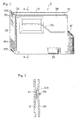
- Fig. 1 is a perspective illustration showing appearance of the cartridge type server unit according to the invention.
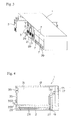
- Fig. 2 is a vertical sectional view as taken along the line A-A.
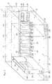
- Fig. 3 is a perspective illustration schematically showing a state in which cartridge type server units are accommodated in the server unit cabinet.
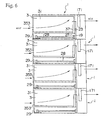
- Fig. 4 is a vertical sectional view as taken along the line B-B according to Fig. 3 illustrating the state in which said cartridge type server units are accommodated in the server unit cabinet.
- Fig. 5 is a perspective view conceptually illustrating the structure of the server unit cabinet. In Figs. 3 through 5, the frame structuring the server unit cabinet is indicated in solid lines without any dimension.
- a cartridge type serve unit 3 comprises a front panel 35, a printed circuit board 31 (mother board) for a server unit, one side of which is attached to a rear of the front panel 35, a heat sink 33 which is assembled next to the printed circuit board 31 for the server unit, and a main connector 37 which is provided on one side opposite to the printed circuit board 31 for the server unit and the front panel 35 and which has a data input/output terminal and a power inlet terminal.
- the front panel 35 has a height of 4 units (U) and a width of 25.4 mm (1 inch).
- the surface thereof is provided with an input/output connector 315 for maintenance use, air vents 353 for cooling, and a grip 355.
- the bottom thereof is provided with a support for the printed circuit board 35 for the server unit, which is not illustrated, and means for retaining the front panel 35 when the server unit 3 is accommodated in a server unit cabinet 1.
- the printed circuit board 31 for the server unit is sized, e.g., as 160 x 233.35mm, and equipped with a CPU 311 and memory so that it can provide functions to perform the necessary processing as the server unit 3.
- the printed circuit board 31 for the server unit does not incorporate a constant-voltage power source or the like which can be shared by multiple server units 3.
- the printed circuit board 31 for the server unit provides a main connector 37 having a signal input/output terminal and a power inlet terminal on one side thereof, opposite to the front panel 35.
- the printed circuit board 31 for the server unit also provides on the surface thereof, an extension connector 39 for connecting an extension board (daughter board) 5 which will be installed adjacent thereto.
- a heat sink 33 which is supported by a support 31 at a given clearance from the printed circuit board 31 for the server unit, is formed of aluminum or a similar material with high thermal conductivity and has almost the same size as that of the printed circuit board 31 for the server unit. As shown in the sectional view of Fig. 2, the heat sink 33 is installed so that it makes contact with highly heat-generating members mounted on the printed circuit board 31 for the server unit, such as the CPU 311 and memory chip, via a heat-conductive sheet 313 or the like. To radiate heat from a heat-generating area by the entire heat sink 33, a heat pipe 331 is provided so that it runs from the heat-generating area to a lower-temperature area. Thus, heat is distributed across the heat sink 33.
- a server unit cabinet 1 accommodates multiple said server units 3 and multiple power sources such as constant-voltage power sources.
- a front panel located on the front lower part of the server unit cabinet 1 is provided with, e.g., three external signal input/output connectors 29 for each server unit.
- 10 server unit cabinets 3 are stacked in a server unit rack.
- cartridge type server units 3 are accommodated in the server unit cabinet 1, and one power source 7 is also accommodated for each group consisting of several server units 3 therein.
- an extension board (daughter board) 5 which extends the functions of the cartridge type server unit 3 may be connected.
- the server unit cabinet 1 is configured so as to provide a server unit space 11, a power source space 13, a signal transmission means space 15, a cooling space 17, a wiring circuit board 19, and an external signal input/output connector 29.
- the server unit space 11 is used to accommodate multiple server units 3. As illustrated in Fig. 4, a guide rail 12 which guides and supports the server unit 3 so that a main connector provided on the server unit 3 is connected to a server unit connector 23 on the wiring circuit board 19, is provided in the server unit space 11.
- the power source space 13 is used to install the constant-voltage power source 7 which converts the electric energy received from a commercial power source or a similar external power source into server drive voltage and which makes said voltage constant and then outputs it to the server unit 3. Said power source space 13 is laid out next to the server space 11.
- guiding means which, though not illustrated, guides the constant-voltage power source 7 so that a connector provided on the constant-voltage power source 7 is connected to a power connector 25 provided on the wiring circuit board, are provided in the power source space 13.
- the signal transmission means space 15 is used to accommodate wiring and other connection means such as a connection cord with a connector. Said signal transmission means space 15 is provided below the server unit space 11 and the power source space 13.
- the cooling space 17 is used to have cooling fans 171 and 172 provided on the rear of the server unit cabinet 1, so that air is carried out of the server unit space 11 and the power source space 13.
- the cooling space 17 is laid out behind the server unit space 11 and the power source space 13.
- One cooling fan 171 is installed for multiple server units 3, and one cooling fan 172 for one power source.
- a wiring circuit board 19 is located behind the server unit space 11, the power source space 13, and the signal transmission means space 15.
- a wiring circuit board 29 is, for example, formed as a printed circuit board and has (a) server connectors 23, the number of which corresponds to the number of server units 3 to be accommodated in the server unit cabinet 1, and which are located in positions corresponding to the server unit space 11, (b) power connectors 25, the number of which corresponds to the number of power sources 7 located in position corresponding to the power source space 13, and signal input/output points 27 located in positions corresponding to the signal transmission means space 13.
- a server connector has a signal input/output terminal which is used to input signals to and output signals from signals a server unit 3, and a power outlet terminal which is used to supply the server unit with constant voltage.
- the server connector is oriented toward the server unit space 11.
- a power connector 25 consists of an external power outlet terminal which is used to supply electric power from an external power source to the constant-voltage power source 7 connected to said external power source, and a constant-voltage terminal which is used to supply constant-voltage power from the constant-voltage power source to the power inlet terminal of the server unit connector 23. Said power connect 25 is oriented toward the power source space 13.
- a signal input/output point 27 is used to send signals from the server unit 3 to the external signal input/output connector 29 and formed as a relay connector or a connection terminal.
- the power outlet terminal of the server connector 23 and the constant-voltage terminal of the power connector 25 are connected by wiring on the wiring circuit board 19.
- the signal input/output terminal and signal input/output point of the server connector 23 are connected by wiring on the wiring circuit board 19.
- the external signal input/output connectors 29 are provided, in the numbers corresponding to the number of server units 3 to be accommodated in the server unit cabinet 1, on the front panel 21 of the server unit cabinet 1. Said external signal input/output connectors 29 are connected to signal input/output points on the wiring circuit board via connection means.
- connection means e.g., serial signal connectors such as RS-232C connectors, and LAN connectors are used.
- connection means 28 such as wiring or cords having a connector.
- the printed circuit board 31 for the server unit 3 is guided into an inner side by the guide rail 12. Then, the main connector 37 completes the connection between the server unit 3 inserted into the server connector 23 and the external signal input/output connector 29, thus enabling signal input to and output from the external signal input/output connector 29 provided on the front.
- the constant-voltage power source 7 is guided via guiding means and then a connector provided thereon is connected to the power connector 25 provided on the wiring circuit board 19.
- the connections between the external power source, the constant-voltage power source 7, and each server unit 3 are completed very easily.
- FIG. 6 is a vertical sectional view schematically illustrating a state wherein multiple server units 1 are stacked in the server unit rack.
- the server unit space 11 in the server unit cabinet 1 is a closed space except for the front and rear thereof. Therefore, when the server unit cooling fan 171 located in the cooling fan space 17 is operated, air flows, along the heat sink 33, from the air vents 353 provided on the lower part of the front panel 35 of the server unit 3 to the server unit cooling fan 171. Since the heat sink 33 is provided with a heat pipe which transmits heat from the heat-generating part on the printed circuit board 31 to another part, the heat can be taken out efficiently.
- the server unit 3 is formed on the printed circuit board 31 which has a CPU and memory without a power source, and designed as a cartridge type having the main connector 37 on the rear thereof.
- the server unit cabinet 1 is provided with the server connector 23 which is connected to the external signal input/output connector 29 located on the front of the server unit cabinet 1. Therefore, merely inserting the cartridge type server unit 3 into the server unit cabinet completes the wiring. This allows for greatly simplifying the wiring for adding any server unit and prevents any connection error.
- the invention eliminates the power source from the server unit 3, allowing for downsizing the section having the server function.
- the printed circuit board 31 incorporating the server function is positioned vertically and the heat sink is provided to enable efficient cooling.
- multiple server units can be installed in a single server unit rack so that the space for installing the server units can be greatly saved.
Abstract
Description
- The present invention relates to a cartridge type server unit comprising (a) a printed circuit board for a server unit, mounted with a CPU and memory which operate with external constant voltage, (b) a front panel which supports the printed circuit board for the server unit, and (c) connectors provided on the printed circuit board for the server unit, and eliminating the need of additional wiring. The invention also relates to a server unit cabinet which accommodates multiple pieces of said server unit therein.
- With rapid development of the Internet, burdens on Internet servers have become so large that servers might hang up. To cope with an increased load on servers, one option is to increase the capacity of a server itself. However, such a capacity increase has a limit, and multiple server units are installed to disperse the increased load.
- If multiple server units are grouped so as to function as a single server, each server unit is not required to be a high-performance workstation, but a so-called PC server can well do for the purpose. In this case, several hundred PC servers must be installed on one site. When a user accesses this site, he/she will be led to one of the installed PC servers. An increase in the load can be coped with by increasing PC servers.
- To install several hundred server units, a considerably large space is required. If it is taken into account that a power source, a cooling method, and safety control be provided, the cost for the installation space will further increase. In addition, it is predicted that several server units will be added every month. The maintenance work including accurate wiring and replacement of server units which have failed will become a very serious problem.
- Normally, on a site where a larger number of server units are installed, multiple server units are accommodated in a server unit rack which extends vertically, so that the space can be effectively utilized in that direction. For example, a server unit rack called a 19" rack has a width of 19 inches (482.6 mm) and a height equivalent to 42 units (1871.1 mm: 1 U = 44.45 mm). If typical tower type server units are used, a single rack allows only 4 to 6 units to be installed.
- In order to solve this problem with the space for installing server units, a server unit with a thickness of 1 U has been developed. 42 units of said server have been stacked without clearance in a single rack. In this method, however, since a CPU and an HDD must be incorporated in a space of 1 U in thickness, it is difficult to handle heating from these components. As a result, the thickness of a server unit has been changed from 1 U back to 2 U, and clearance for ventilation has been provided for each server unit. Therefore, the number of server units which can practically be installed has decreased to approximately a half.
- When a larger number of server units are to be accommodated in a server unit cabinet, it is necessary to supply each server unit with electric power and to connect wiring for signal input/output. These connections are made on the rear of the server unit cabinet. To ensure accuracy, therefore, great care must be taken and troublesome work is required.
- The present invention aims to provide a server unit which is designed to allow a larger number of server units to be accommodated in a server unit cabinet and to be efficiently cooled therein.
- It is a further object of the invention to provide a server unit cabinet which can be installed in a server unit rack and which allows multiple server units to be accommodated therein.
- An even further object of the invention contemplates the provision of structures of the server unit and server unit cabinet which allow for easily and efficiently making a connection between the server unit and any external device and for quite easily making a connection for power supply.
- In order to solve said problem, this invention comprises (a) a printed circuit board for a server unit, which is equipped with a central processing unit (CPU) and main memory and which serves as a computer with the supply of external electric power, (b) a heat sink supported by the printed circuit board for the server unit, and (c) a front panel which supports the printed circuit board for the server unit. The structure of said server unit is such that the front panel supports the printed circuit board for the server unit so as to vertically position a flat surface of the printed circuit board for the server unit when accommodating the server unit, that a part of the heat sink makes contact with highly heat-generating components mounted on the printed circuit board for the server unit via heat conduction means, and that heat conduction means are provided to transmit heat from said contacting part to another part of the heat sink.
- According to the invention, the cartridge type server unit is such that a connector having a signal input/output terminal and a power inlet terminal is provided on one side opposite to the side supported by the front panel of the printed circuit board for the server unit.
- According to the invention, the cartridge type server unit is such that an extension connector to which an extension board is connected is provided on one surface of the printed circuit board for the server unit.
- According to the invention, the cartridge type server unit is such that a heat pipe is used to form the heat transmission means to be provided for the heat sink.
- According to the invention, the cartridge type server unit is such that an input/output connector for maintenance use is provided on the front panel and that air vents for cooling are provided on the lower part of the front panel.
- In order to further solve the problem, the invention provides a server unit cabinet for accommodating multiple pieces of said cartridge type server unit and at least one constant-voltage power source therein with a server unit space for accommodating multiple server units, a power source space for mounting at least one constant-voltage power source, a signal transmission means space for accommodating signal transmission means, and a cooling space for accommodating cooling means. The invention further provides the server unit cabinet with a server unit connector having a signal input/output terminal and a constant-voltage outlet terminal, and with a power connector having a signal input/output point, an external power inlet terminal, and a constant-voltage power inlet terminal. The invention even further provides the server unit cabinet with (a) a wiring circuit board which includes wiring between the constant-voltage inlet terminal of the power connector and the constant-voltage outlet terminal of the server unit connector, and wiring between the signal input/output terminal of the server unit connector and the signal input/output point, (b) an external signal input/output connector provided on the front of the server unit cabinet, and (c) signal transmission means which connects between said external signal input/output connector and the signal input/output point of said wiring circuit board.
- According to the invention the server unit cabinet is such that the input/output point provided on the wiring circuit board is structured as a relay connector, and that the signal transmission means are a cable having a connector which is connected to said relay connector.
- According to the invention, the server unit cabinet is such that the signal transmission means connecting between the input/output point provided on the wiring circuit board and the external signal input/output connector are wiring.
- According to the invention, the server unit cabinet is such that cooling fans are used as the cooling means.
- According to the invention, the server unit cabinet is such that means for guiding a server unit so that a connector provided on the server unit connects to the server unit connector on the wiring circuit board, are provided in the server unit space.
- According to the invention, the server unit cabinet is such that means for guiding a constant-voltage power source so that a connector provided on the constant-voltage power source connects to the power connector on the wiring circuit board, are provided in the power source space.
-
- FIG. 1 is a perspective illustration showing the appearance of the server unit according to the invention;
- FIG. 2 is a vertical sectional illustration showing the cross section as viewed along the line A-A in Fig. 1;
- FIG. 3 is a perspective illustration showing the appearance of the cabinet for accommodating server units according to this invention;
- FIG. 4 is a vertical sectional illustration showing the cross section as viewed along the line B-B;
- FIG. 5 is a perspective illustration diagrammatically showing the configuration of the cabinet for accommodating server units, which is illustrated in Fig. 3; and
- FIG. 6 is a vertical sectional illustration showing the state in which cabinets for accommodating server units are installed in a server unit rack.
-
- The configuration of the cartridge type server unit and the server unit cabinet to accommodate cartridge type server units, according to this invention, is described referring to Figs. 1 through 5.
- According to the invention, the cartridge type server unit comprises (a) a printed circuit board for a server unit, on which a CPU (central processing unit) and main memory are mounted, (b) a main connector that centrally provides a power port for constant-voltage inlet mounted on the printed circuit board for the server unit, two LAN ports for signal input/output, and a serial port, (c) a heat sink which partially contacts with highly heat-generating elements mounted on the printed circuit board for the server unit, and (d) a front panel which supports the printed circuit board for the server unit so that a wiring surface thereof is positioned vertically.
- Fig. 1 is a perspective illustration showing appearance of the cartridge type server unit according to the invention. Fig. 2 is a vertical sectional view as taken along the line A-A. Fig. 3 is a perspective illustration schematically showing a state in which cartridge type server units are accommodated in the server unit cabinet. Fig. 4 is a vertical sectional view as taken along the line B-B according to Fig. 3 illustrating the state in which said cartridge type server units are accommodated in the server unit cabinet. Fig. 5 is a perspective view conceptually illustrating the structure of the server unit cabinet. In Figs. 3 through 5, the frame structuring the server unit cabinet is indicated in solid lines without any dimension.
- As illustrated in Figs . 1 and 2, a cartridge type serve
unit 3 according to the invention comprises afront panel 35, a printed circuit board 31 (mother board) for a server unit, one side of which is attached to a rear of thefront panel 35, aheat sink 33 which is assembled next to the printedcircuit board 31 for the server unit, and amain connector 37 which is provided on one side opposite to the printedcircuit board 31 for the server unit and thefront panel 35 and which has a data input/output terminal and a power inlet terminal. - The
front panel 35 has a height of 4 units (U) and a width of 25.4 mm (1 inch). The surface thereof is provided with an input/output connector 315 for maintenance use,air vents 353 for cooling, and agrip 355. The bottom thereof is provided with a support for the printedcircuit board 35 for the server unit, which is not illustrated, and means for retaining thefront panel 35 when theserver unit 3 is accommodated in a server unit cabinet 1. - The printed
circuit board 31 for the server unit is sized, e.g., as 160 x 233.35mm, and equipped with aCPU 311 and memory so that it can provide functions to perform the necessary processing as theserver unit 3. However, the printedcircuit board 31 for the server unit does not incorporate a constant-voltage power source or the like which can be shared bymultiple server units 3. The printedcircuit board 31 for the server unit provides amain connector 37 having a signal input/output terminal and a power inlet terminal on one side thereof, opposite to thefront panel 35. The printedcircuit board 31 for the server unit also provides on the surface thereof, anextension connector 39 for connecting an extension board (daughter board) 5 which will be installed adjacent thereto. - A
heat sink 33 which is supported by asupport 31 at a given clearance from the printedcircuit board 31 for the server unit, is formed of aluminum or a similar material with high thermal conductivity and has almost the same size as that of the printedcircuit board 31 for the server unit. As shown in the sectional view of Fig. 2, theheat sink 33 is installed so that it makes contact with highly heat-generating members mounted on the printedcircuit board 31 for the server unit, such as theCPU 311 and memory chip, via a heat-conductive sheet 313 or the like. To radiate heat from a heat-generating area by theentire heat sink 33, aheat pipe 331 is provided so that it runs from the heat-generating area to a lower-temperature area. Thus, heat is distributed across theheat sink 33. - As illustrated in Fig. 3, a server unit cabinet 1 accommodates multiple said
server units 3 and multiple power sources such as constant-voltage power sources. A front panel located on the front lower part of the server unit cabinet 1 is provided with, e.g., three external signal input/output connectors 29 for each server unit. For example, 10server unit cabinets 3 are stacked in a server unit rack. - Multiple cartridge
type server units 3 are accommodated in the server unit cabinet 1, and onepower source 7 is also accommodated for each group consisting ofseveral server units 3 therein. To the cartridgetype server unit 3 accommodated in the server unit cabinet 1, an extension board (daughter board) 5 which extends the functions of the cartridgetype server unit 3 may be connected. - As illustrated in Figs. 4 and 5, the server unit cabinet 1 is configured so as to provide a server unit space 11, a
power source space 13, a signal transmission meansspace 15, a coolingspace 17, awiring circuit board 19, and an external signal input/output connector 29. - The server unit space 11 is used to accommodate
multiple server units 3. As illustrated in Fig. 4, aguide rail 12 which guides and supports theserver unit 3 so that a main connector provided on theserver unit 3 is connected to aserver unit connector 23 on thewiring circuit board 19, is provided in the server unit space 11. - The
power source space 13 is used to install the constant-voltage power source 7 which converts the electric energy received from a commercial power source or a similar external power source into server drive voltage and which makes said voltage constant and then outputs it to theserver unit 3. Saidpower source space 13 is laid out next to the server space 11. In addition, guiding means which, though not illustrated, guides the constant-voltage power source 7 so that a connector provided on the constant-voltage power source 7 is connected to apower connector 25 provided on the wiring circuit board, are provided in thepower source space 13. - Various kinds of units other than the constant-
voltage power source 7, which are common tomultiple server units 3, may be installed in thepower source space 13. - The signal transmission means
space 15 is used to accommodate wiring and other connection means such as a connection cord with a connector. Said signal transmission meansspace 15 is provided below the server unit space 11 and thepower source space 13. - The cooling
space 17 is used to have coolingfans power source space 13. The coolingspace 17 is laid out behind the server unit space 11 and thepower source space 13. Onecooling fan 171 is installed formultiple server units 3, and onecooling fan 172 for one power source. - A
wiring circuit board 19 is located behind the server unit space 11, thepower source space 13, and the signal transmission meansspace 15. Awiring circuit board 29 is, for example, formed as a printed circuit board and has (a)server connectors 23, the number of which corresponds to the number ofserver units 3 to be accommodated in the server unit cabinet 1, and which are located in positions corresponding to the server unit space 11, (b)power connectors 25, the number of which corresponds to the number ofpower sources 7 located in position corresponding to thepower source space 13, and signal input/output points 27 located in positions corresponding to the signal transmission meansspace 13. - A server connector has a signal input/output terminal which is used to input signals to and output signals from signals a
server unit 3, and a power outlet terminal which is used to supply the server unit with constant voltage. The server connector is oriented toward the server unit space 11. - A
power connector 25 consists of an external power outlet terminal which is used to supply electric power from an external power source to the constant-voltage power source 7 connected to said external power source, and a constant-voltage terminal which is used to supply constant-voltage power from the constant-voltage power source to the power inlet terminal of theserver unit connector 23. Said power connect 25 is oriented toward thepower source space 13. - A signal input/
output point 27 is used to send signals from theserver unit 3 to the external signal input/output connector 29 and formed as a relay connector or a connection terminal. - The power outlet terminal of the
server connector 23 and the constant-voltage terminal of thepower connector 25 are connected by wiring on thewiring circuit board 19. The signal input/output terminal and signal input/output point of theserver connector 23 are connected by wiring on thewiring circuit board 19. - The external signal input/
output connectors 29 are provided, in the numbers corresponding to the number ofserver units 3 to be accommodated in the server unit cabinet 1, on thefront panel 21 of the server unit cabinet 1. Said external signal input/output connectors 29 are connected to signal input/output points on the wiring circuit board via connection means. For said connection means, e.g., serial signal connectors such as RS-232C connectors, and LAN connectors are used. - The input/
output points 27 and external signal input/output connectors 29 on the wiring circuit board are connected using the connection means 28 such as wiring or cords having a connector. - To accommodate the
server unit 3 in the server unit cabinet 1 which has said configuration, the printedcircuit board 31 for theserver unit 3 is guided into an inner side by theguide rail 12. Then, themain connector 37 completes the connection between theserver unit 3 inserted into theserver connector 23 and the external signal input/output connector 29, thus enabling signal input to and output from the external signal input/output connector 29 provided on the front. - Similarly, to mount the
power source 7 in the server unit cabinet 1, the constant-voltage power source 7 is guided via guiding means and then a connector provided thereon is connected to thepower connector 25 provided on thewiring circuit board 19. Thus, the connections between the external power source, the constant-voltage power source 7, and eachserver unit 3 are completed very easily. - Referring to Fig. 6, this paragraph describes how each server unit cabinet accommodating
multiple server units 3 is cooled when the server unit cabinet is installed in the server unit rack. Fig. 6 is a vertical sectional view schematically illustrating a state wherein multiple server units 1 are stacked in the server unit rack. As illustrated in this figure, the server unit space 11 in the server unit cabinet 1 is a closed space except for the front and rear thereof. Therefore, when the serverunit cooling fan 171 located in the coolingfan space 17 is operated, air flows, along theheat sink 33, from the air vents 353 provided on the lower part of thefront panel 35 of theserver unit 3 to the serverunit cooling fan 171. Since theheat sink 33 is provided with a heat pipe which transmits heat from the heat-generating part on the printedcircuit board 31 to another part, the heat can be taken out efficiently. - As described above, according to this invention, the
server unit 3 is formed on the printedcircuit board 31 which has a CPU and memory without a power source, and designed as a cartridge type having themain connector 37 on the rear thereof. The server unit cabinet 1 is provided with theserver connector 23 which is connected to the external signal input/output connector 29 located on the front of the server unit cabinet 1. Therefore, merely inserting the cartridgetype server unit 3 into the server unit cabinet completes the wiring. This allows for greatly simplifying the wiring for adding any server unit and prevents any connection error. - The invention eliminates the power source from the
server unit 3, allowing for downsizing the section having the server function. In addition, the printedcircuit board 31 incorporating the server function is positioned vertically and the heat sink is provided to enable efficient cooling. Thus, multiple server units can be installed in a single server unit rack so that the space for installing the server units can be greatly saved.
Claims (11)
- A cartridge type server unit comprising (a) a printed circuit board for a server unit, which is equipped with a central processing unit (CPU) and main memory and which serves as a computer with the supply of external electric power at constant voltage, (b) a heat sink supported by the printed circuit board for the server unit, and (c) a front panel which supports the printed circuit board for the server unit; and characterized in that the front panel supports the printed circuit board for the server unit so that a flat surface of the printed circuit board for the server unit is positioned vertically when the server unit is installed, that a part of the heat sink makes contact with highly heat-generating components mounted on the printed circuit board for the server unit via heat conduction means, and that heat conduction means are provided to transmit heat from said contacting part to another part of the heat sink.
- A cartridge type server unit according to claim 1, characterized in that a connector having a signal input/output terminal and a power inlet terminal is provided on one side opposite to the side supported by the front panel of the printed circuit board for the server unit.
- A cartridge type server unit according to claim 2, characterized in that an extension connector to which an extension board is connected is provided on one surface of the printed circuit board for the server unit.
- A cartridge type server unit according to claim 1, which uses a heat pipe for the heat transmission means.
- A cartridge type server unit according to claim 4, characterized in that an input/output connector for maintenance use is provided on the front panel and that air vents for cooling are provided on the lower part of the front panel.
- A server unit cabinet for accommodating multiple cartridge type server units and a constant-voltage power source therein, which is characterized in that the server unit cabinet provides a server unit space for accommodating multiple server units, a power source space for mounting at least one constant-voltage power source, a signal transmission space for accommodating signal transmission means, and a cooling space for accommodating cooling means; that the serer unit cabinet is equipped with a server unit connector having a signal input/output terminal and a constant-voltage outlet terminal, and with a power connector having a signal input/output point, an external power inlet terminal, and a constant-voltage power inlet terminal; and that the server unit cabinet provides (a) a wiring circuit board which includes wiring between the constant-voltage inlet terminal of the power connector and the constant-voltage outlet terminal of the server unit connector, and wiring between the signal input/output terminal of the server unit connector and the signal input/output point, (b) an external signal input/output connector provided on the front of the server unit cabinet, and (c) signal transmission means which connects between said external signal input/output connector and the signal input/output point of said wiring circuit board.
- A server unit cabinet according to claim 6, wherein the input/output point provided on the wiring circuit board is structured as a relay connector, and wherein the signal transmission means are a cable having a connector which is connected to said relay connector.
- A server cabinet according to claim 6, wherein the signal transmission means connecting between the input/output point provided on the wiring circuit board and the external signal input/output connector are wiring.
- A server unit cabinet according to claim 6, wherein the cooling means are cooling fans.
- A server unit cabinet according to claim 6, wherein means for guiding a server unit so that a connector provided on the server unit connects to the server unit connector on the wiring circuit board, are provided in the server unit space.
- A server unit cabinet according to claim 6, wherein means for guiding a constant-voltage power source so that a connector provided on the constant-voltage power source connects to the power connector on the wiring circuit board, are provided in the power source space.
Applications Claiming Priority (2)
| Application Number | Priority Date | Filing Date | Title |
|---|---|---|---|
| JP2000219367 | 2000-07-19 | ||
| JP2000219367A JP3565767B2 (en) | 2000-07-19 | 2000-07-19 | Cartridge type server unit, housing for mounting the server unit, and server device |
Publications (2)
| Publication Number | Publication Date |
|---|---|
| EP1175136A2 true EP1175136A2 (en) | 2002-01-23 |
| EP1175136A3 EP1175136A3 (en) | 2002-05-15 |
Family
ID=18714165
Family Applications (1)
| Application Number | Title | Priority Date | Filing Date |
|---|---|---|---|
| EP01117393A Withdrawn EP1175136A3 (en) | 2000-07-19 | 2001-07-18 | A cartridge type server unit and a cabinet to accommodate multiple said server units |
Country Status (5)
| Country | Link |
|---|---|
| US (2) | US6621713B2 (en) |
| EP (1) | EP1175136A3 (en) |
| JP (1) | JP3565767B2 (en) |
| CN (1) | CN1333488A (en) |
| TW (1) | TW535046B (en) |
Cited By (4)
| Publication number | Priority date | Publication date | Assignee | Title |
|---|---|---|---|---|
| US6654252B2 (en) * | 2001-07-18 | 2003-11-25 | Hewlett-Packard Development Company, L.P. | Server system with removable server cartridges |
| EP1531384A2 (en) * | 2003-11-14 | 2005-05-18 | LG Electronics Inc. | Cooling apparatus for portable computer |
| FR2910779A1 (en) * | 2006-12-21 | 2008-06-27 | Thales Sa | Electronic equipment casing i.e. electronic rack, for aircraft, has heat collectors inserted between hot spots and inner thermal radiators, and heat conductors connecting outer thermal radiator with collectors through front wall of casing |
| CN102566711A (en) * | 2010-12-09 | 2012-07-11 | 鸿富锦精密工业(深圳)有限公司 | Server cabinet |
Families Citing this family (66)
| Publication number | Priority date | Publication date | Assignee | Title |
|---|---|---|---|---|
| US7630198B2 (en) * | 2006-03-08 | 2009-12-08 | Cray Inc. | Multi-stage air movers for cooling computer systems and for other uses |
| KR100911700B1 (en) * | 2002-05-31 | 2009-08-10 | 베라리 시스템즈, 인코포레이티드 | A rack system for mounting components |
| US6804117B2 (en) * | 2002-08-14 | 2004-10-12 | Thermal Corp. | Thermal bus for electronics systems |
| US7130190B1 (en) | 2002-11-18 | 2006-10-31 | Span, Inc. | Computer servicing cart |
| US7191347B2 (en) * | 2002-12-31 | 2007-03-13 | International Business Machines Corporation | Non-disruptive power management indication method, system and apparatus for server |
| US6914780B1 (en) * | 2003-01-16 | 2005-07-05 | Cisco Technology, Inc. | Methods and apparatus for cooling a circuit board component using a heat pipe assembly |
| JP2005005349A (en) * | 2003-06-10 | 2005-01-06 | Hit:Kk | Electronic apparatus |
| US7013955B2 (en) * | 2003-07-28 | 2006-03-21 | Thermal Corp. | Flexible loop thermosyphon |
| JP4371210B2 (en) * | 2003-12-05 | 2009-11-25 | 日本電気株式会社 | Electronic unit and heat dissipation structure |
| US7457118B1 (en) * | 2003-12-19 | 2008-11-25 | Emc Corporation | Method and apparatus for dispersing heat from high-power electronic devices |
| US7074123B2 (en) * | 2004-01-13 | 2006-07-11 | Power Of 4, L.L.C. | Cabinet for computer devices with air distribution device |
| US7180737B2 (en) * | 2004-12-20 | 2007-02-20 | Harris Corporation | Heat exchanger system for circuit card assemblies |
| US20060138213A1 (en) * | 2004-12-28 | 2006-06-29 | Kang Hyun K | Control unit of a cash transaction machine and multi channel connecting device |
| JP4595645B2 (en) | 2005-04-19 | 2010-12-08 | 株式会社日立製作所 | COMPOUND COMPUTER DEVICE AND METHOD FOR MANAGING COMPOSITE COMPUTER DEVICE |
| JP4555140B2 (en) | 2005-04-22 | 2010-09-29 | 株式会社日立製作所 | Compound computer apparatus and management method thereof |
| TWI296750B (en) * | 2005-12-20 | 2008-05-11 | Asustek Comp Inc | Heat-dissipating device coupled by a heat pipe |
| JP4650278B2 (en) | 2006-01-19 | 2011-03-16 | 株式会社日立製作所 | Complex information platform device and management method of complex information platform device |
| JP4609331B2 (en) | 2006-01-27 | 2011-01-12 | 株式会社日立製作所 | Complex information platform apparatus and communication bandwidth guarantee method thereof |
| US20070211439A1 (en) * | 2006-03-08 | 2007-09-13 | Hit Co., Ltd. | Electronic apparatus having drawer trays |
| US20080043442A1 (en) * | 2006-08-16 | 2008-02-21 | Strickland Travis C | Computer system with thermal conduction |
| US20090009958A1 (en) * | 2007-07-02 | 2009-01-08 | John Pflueger | System and Method for Rack Mounted Information Handling System Supplemental Cooling |
| US7447024B1 (en) * | 2007-07-17 | 2008-11-04 | Kuan-Yin Chou | Heat sink for a memory |
| US7688578B2 (en) * | 2007-07-19 | 2010-03-30 | Hewlett-Packard Development Company, L.P. | Modular high-density computer system |
| US8223494B2 (en) * | 2007-12-31 | 2012-07-17 | General Electric Company | Conduction cooled circuit board assembly |
| US7639486B2 (en) * | 2007-12-13 | 2009-12-29 | International Business Machines Corporation | Rack system providing flexible configuration of computer systems with front access |
| US20090154091A1 (en) | 2007-12-17 | 2009-06-18 | Yatskov Alexander I | Cooling systems and heat exchangers for cooling computer components |
| JP5154238B2 (en) | 2008-01-18 | 2013-02-27 | 株式会社日立製作所 | Management method of composite computer system and composite computer system |
| US8170724B2 (en) * | 2008-02-11 | 2012-05-01 | Cray Inc. | Systems and associated methods for controllably cooling computer components |
| US7898799B2 (en) * | 2008-04-01 | 2011-03-01 | Cray Inc. | Airflow management apparatus for computer cabinets and associated methods |
| JP5262404B2 (en) * | 2008-08-04 | 2013-08-14 | 株式会社日立製作所 | COMPOUND COMPUTER AND METHOD FOR CONTROLLING COMPOSITE COMPUTER |
| US11294135B2 (en) | 2008-08-29 | 2022-04-05 | Corning Optical Communications LLC | High density and bandwidth fiber optic apparatuses and related equipment and methods |
| US8452148B2 (en) | 2008-08-29 | 2013-05-28 | Corning Cable Systems Llc | Independently translatable modules and fiber optic equipment trays in fiber optic equipment |
| JP4812138B2 (en) | 2008-09-24 | 2011-11-09 | 株式会社日立製作所 | COOLING DEVICE AND ELECTRONIC DEVICE HAVING THE SAME |
| JP5272265B2 (en) | 2008-09-29 | 2013-08-28 | 株式会社日立製作所 | PCI device sharing method |
| US8081459B2 (en) * | 2008-10-17 | 2011-12-20 | Cray Inc. | Air conditioning systems for computer systems and associated methods |
| US7903403B2 (en) * | 2008-10-17 | 2011-03-08 | Cray Inc. | Airflow intake systems and associated methods for use with computer cabinets |
| JP5332000B2 (en) | 2008-12-17 | 2013-10-30 | 株式会社日立製作所 | COMPUTER COMPUTER DEVICE, COMPOSITE COMPUTER MANAGEMENT METHOD, AND MANAGEMENT SERVER |
| TWM366286U (en) * | 2009-02-13 | 2009-10-01 | Asia Vital Components Co Ltd | Heat dissipation structure of communication case |
| ES2793952T3 (en) | 2009-06-19 | 2020-11-17 | Corning Optical Communications LLC | High Density and Bandwidth Fiber Optic Apparatus |
| US9036351B2 (en) | 2009-06-22 | 2015-05-19 | Xyber Technologies, Llc | Passive cooling system and method for electronics devices |
| US8582298B2 (en) * | 2009-06-22 | 2013-11-12 | Xyber Technologies | Passive cooling enclosure system and method for electronics devices |
| US8451600B1 (en) * | 2010-03-04 | 2013-05-28 | Amazon Technologies, Inc. | Heat spreading chassis for rack-mounted computer system |
| US8472181B2 (en) | 2010-04-20 | 2013-06-25 | Cray Inc. | Computer cabinets having progressive air velocity cooling systems and associated methods of manufacture and use |
| US9519118B2 (en) | 2010-04-30 | 2016-12-13 | Corning Optical Communications LLC | Removable fiber management sections for fiber optic housings, and related components and methods |
| CN101853059B (en) * | 2010-05-12 | 2013-08-21 | 姚学民 | Cloud computing server system for heat dissipation, energy conservation and safe data storage |
| TW201144994A (en) * | 2010-06-15 | 2011-12-16 | Hon Hai Prec Ind Co Ltd | Server and server system |
| JP2012069685A (en) * | 2010-09-22 | 2012-04-05 | Panasonic Corp | Electronic apparatus |
| WO2012106510A2 (en) | 2011-02-02 | 2012-08-09 | Corning Cable Systems Llc | Dense fiber optic connector assemblies and related connectors and cables suitable for establishing optical connections for optical backplanes in equipment racks |
| TWM413895U (en) | 2011-05-19 | 2011-10-11 | Pegatron Corp | Rack mountable server |
| US10209003B2 (en) | 2012-02-21 | 2019-02-19 | Thermal Corp. | Electronics cabinet and rack cooling system and method |
| US9285845B2 (en) * | 2012-12-27 | 2016-03-15 | Intel Corporation | Method and apparatus for cooling devices using phase change materials |
| WO2014158143A1 (en) | 2013-03-26 | 2014-10-02 | Hewlett-Packard Development Company, L.P. | Top loading cartridge |
| US10178807B2 (en) | 2013-03-26 | 2019-01-08 | Hewlett Packard Enterprise Development Lp | Top loading cartridge |
| EP2979149A4 (en) | 2013-03-26 | 2017-04-19 | Hewlett-Packard Enterprise Development LP | Top loading cartridge |
| US9345166B2 (en) * | 2013-12-30 | 2016-05-17 | Microsoft Technology Licensing, Llc | Rackless computing equipment construction |
| WO2015156817A1 (en) * | 2014-04-11 | 2015-10-15 | Hewlett-Packard Development Company, L. P. | Liquid coolant supply |
| USD748638S1 (en) | 2014-07-10 | 2016-02-02 | Bae Systems Information And Electronic Systems Integration Inc. | Front panel with openings for air cooling a data storage transfer archive repository |
| USD748093S1 (en) | 2014-07-10 | 2016-01-26 | Bae Systems Information And Electronic Systems Integration Inc. | Data storage transfer archive repository |
| USD748627S1 (en) | 2014-07-10 | 2016-02-02 | Bae Systems Information And Electronic Systems Integration Inc. | Front panel with openings for air cooling a data storage transfer archive repository |
| FR3024935B1 (en) * | 2014-08-14 | 2018-03-02 | Zodiac Aero Electric | CONNECTION SYSTEM FOR PROTECTING CARDS OF A DISTRIBUTION SYSTEM AND RACK INCORPORATING SAID SYSTEM |
| US9370090B2 (en) * | 2014-09-29 | 2016-06-14 | General Electric Company | Circuit card assembly and method of manufacturing thereof |
| US9832912B2 (en) | 2015-05-07 | 2017-11-28 | Dhk Storage, Llc | Computer server heat regulation utilizing integrated precision air flow |
| JP6862244B2 (en) * | 2017-03-30 | 2021-04-21 | 株式会社東芝 | Control box and how to assemble the control box |
| CN109472099A (en) * | 2018-11-19 | 2019-03-15 | 郑州云海信息技术有限公司 | A kind of printed circuit board and production method of server |
| CN110536579A (en) * | 2019-08-22 | 2019-12-03 | 北京比特大陆科技有限公司 | Server |
| CN212906117U (en) * | 2020-08-10 | 2021-04-06 | 北京硅基远航科技有限公司 | Server |
Citations (3)
| Publication number | Priority date | Publication date | Assignee | Title |
|---|---|---|---|---|
| US5339214A (en) * | 1993-02-12 | 1994-08-16 | Intel Corporation | Multiple-fan microprocessor cooling through a finned heat pipe |
| US5684671A (en) * | 1995-08-22 | 1997-11-04 | Sequent Computer Systems, Inc. | Packaging architecture for a data server |
| US5986882A (en) * | 1997-10-16 | 1999-11-16 | Compaq Computer Corporation | Electronic apparatus having removable processor/heat pipe cooling device modules therein |
Family Cites Families (12)
| Publication number | Priority date | Publication date | Assignee | Title |
|---|---|---|---|---|
| ES2024412B3 (en) * | 1985-12-13 | 1992-03-01 | Hasler Ag Ascom | PROCEDURE AND DEVICE FOR THE EVACUATION OF LOST HEAT FROM AT LEAST ONE GROUP OF CONSTRUCTION OF ELECTRICAL ELEMENTS |
| JPH0629683A (en) * | 1992-03-31 | 1994-02-04 | Furukawa Electric Co Ltd:The | Heat pipe type heat dissipation unit for electronic apparatus |
| US5684674A (en) * | 1996-01-16 | 1997-11-04 | Micronics Computers Inc. | Circuit board mounting brackets with convective air flow apertures |
| US5731954A (en) * | 1996-08-22 | 1998-03-24 | Cheon; Kioan | Cooling system for computer |
| JP2874684B2 (en) * | 1997-03-27 | 1999-03-24 | 日本電気株式会社 | Heat dissipation structure of plug-in unit |
| US5852547A (en) * | 1997-07-14 | 1998-12-22 | Sun Microsystems, Inc. | Module shroud attachment to motherboard |
| TW441812U (en) * | 1998-01-21 | 2001-06-16 | Hon Hai Prec Ind Co Ltd | Computer fan position apparatus |
| EP0946085A1 (en) * | 1998-03-24 | 1999-09-29 | Lucent Technologies Inc. | Electronic apparatus having an environmentally sealed external enclosure |
| JP2001057492A (en) * | 1999-08-18 | 2001-02-27 | Furukawa Electric Co Ltd:The | Device and method for cooling case for accommodating electrical heating element |
| US6229704B1 (en) * | 1999-10-19 | 2001-05-08 | Dell Usa, L.P. | Thermal connection system for modular computer system components |
| US6438984B1 (en) * | 2001-08-29 | 2002-08-27 | Sun Microsystems, Inc. | Refrigerant-cooled system and method for cooling electronic components |
| DE20115192U1 (en) * | 2001-09-14 | 2001-11-29 | Portwell Inc | Subcarrier board for the heat sink of the main board |
-
2000
- 2000-07-19 JP JP2000219367A patent/JP3565767B2/en not_active Expired - Fee Related
-
2001
- 2001-06-29 CN CN01117553A patent/CN1333488A/en active Pending
- 2001-07-02 TW TW090116087A patent/TW535046B/en not_active IP Right Cessation
- 2001-07-18 US US09/906,682 patent/US6621713B2/en not_active Expired - Fee Related
- 2001-07-18 EP EP01117393A patent/EP1175136A3/en not_active Withdrawn
-
2003
- 2003-06-11 US US10/458,638 patent/US6724617B2/en not_active Expired - Fee Related
Patent Citations (3)
| Publication number | Priority date | Publication date | Assignee | Title |
|---|---|---|---|---|
| US5339214A (en) * | 1993-02-12 | 1994-08-16 | Intel Corporation | Multiple-fan microprocessor cooling through a finned heat pipe |
| US5684671A (en) * | 1995-08-22 | 1997-11-04 | Sequent Computer Systems, Inc. | Packaging architecture for a data server |
| US5986882A (en) * | 1997-10-16 | 1999-11-16 | Compaq Computer Corporation | Electronic apparatus having removable processor/heat pipe cooling device modules therein |
Non-Patent Citations (1)
| Title |
|---|
| HAMMER AND R L SYLER J R: "Ventilation system for data processing systems" IBM TECHNICAL DISCLOSURE BULLETIN, IBM CORP. NEW YORK, US, vol. 17, no. 9, February 1975 (1975-02), pages 2529-2530, XP002102848 ISSN: 0018-8689 * |
Cited By (8)
| Publication number | Priority date | Publication date | Assignee | Title |
|---|---|---|---|---|
| US6654252B2 (en) * | 2001-07-18 | 2003-11-25 | Hewlett-Packard Development Company, L.P. | Server system with removable server cartridges |
| EP1531384A2 (en) * | 2003-11-14 | 2005-05-18 | LG Electronics Inc. | Cooling apparatus for portable computer |
| EP1531384A3 (en) * | 2003-11-14 | 2006-12-06 | LG Electronics Inc. | Cooling apparatus for portable computer |
| US7325590B2 (en) | 2003-11-14 | 2008-02-05 | Lg Electronics Inc. | Cooling apparatus for portable computer |
| FR2910779A1 (en) * | 2006-12-21 | 2008-06-27 | Thales Sa | Electronic equipment casing i.e. electronic rack, for aircraft, has heat collectors inserted between hot spots and inner thermal radiators, and heat conductors connecting outer thermal radiator with collectors through front wall of casing |
| WO2008080776A1 (en) * | 2006-12-21 | 2008-07-10 | Thales | Electronic device housing cooled by natural and forced ventilation |
| US8542485B2 (en) | 2006-12-21 | 2013-09-24 | Thales | Electronic equipment housing cooled by natural and forced ventilation |
| CN102566711A (en) * | 2010-12-09 | 2012-07-11 | 鸿富锦精密工业(深圳)有限公司 | Server cabinet |
Also Published As
| Publication number | Publication date |
|---|---|
| CN1333488A (en) | 2002-01-30 |
| US6724617B2 (en) | 2004-04-20 |
| JP2002032153A (en) | 2002-01-31 |
| TW535046B (en) | 2003-06-01 |
| JP3565767B2 (en) | 2004-09-15 |
| US20020008961A1 (en) | 2002-01-24 |
| EP1175136A3 (en) | 2002-05-15 |
| US6621713B2 (en) | 2003-09-16 |
| US20030235025A1 (en) | 2003-12-25 |
Similar Documents
| Publication | Publication Date | Title |
|---|---|---|
| US6621713B2 (en) | Cartridge type server unit and a cabinet to accommodate multiple said server units | |
| US7722359B1 (en) | Connection assembly having midplane with enhanced connection and airflow features | |
| US6590768B1 (en) | Ventilating slide rail mount | |
| US8416570B2 (en) | Open frame electronic chassis for enclosed modules | |
| US6975510B1 (en) | Ventilated housing for electronic components | |
| US6137682A (en) | Air-cooled electronic apparatus | |
| US10271460B2 (en) | Server system | |
| US20140029194A1 (en) | High-density server with redundant power source for server modules | |
| JP2015532759A (en) | Axis for electronic equipment | |
| CN101165629A (en) | Computer system cooling system | |
| US7136283B2 (en) | Multi-computer system | |
| JPH0246965B2 (en) | ||
| CN101083894B (en) | Electronic device and heat radiating module | |
| US7236358B2 (en) | Computer system | |
| US8503177B2 (en) | Detachable USB fan module mounting structure | |
| CN109222899B (en) | Monitor | |
| CN215729605U (en) | Server chassis | |
| US20210410323A1 (en) | Assembly with a heat sink core element forming a supporting structure | |
| CN209842460U (en) | Extension type control device and host machine of extension type control device | |
| CN220232393U (en) | Network security computer | |
| CN216014141U (en) | Machine box | |
| CN220041065U (en) | Heat radiating device and chassis | |
| CN218512913U (en) | Computer with a memory card | |
| CN212160557U (en) | Server case and server | |
| CN219143382U (en) | Host case structure and discussion host |
Legal Events
| Date | Code | Title | Description |
|---|---|---|---|
| PUAI | Public reference made under article 153(3) epc to a published international application that has entered the european phase |
Free format text: ORIGINAL CODE: 0009012 |
|
| AK | Designated contracting states |
Kind code of ref document: A2 Designated state(s): AT BE CH CY DE DK ES FI FR GB GR IE IT LI LU MC NL PT SE TR |
|
| AX | Request for extension of the european patent |
Free format text: AL;LT;LV;MK;RO;SI |
|
| PUAL | Search report despatched |
Free format text: ORIGINAL CODE: 0009013 |
|
| AK | Designated contracting states |
Kind code of ref document: A3 Designated state(s): AT BE CH CY DE DK ES FI FR GB GR IE IT LI LU MC NL PT SE TR |
|
| AX | Request for extension of the european patent |
Free format text: AL;LT;LV;MK;RO;SI |
|
| 17P | Request for examination filed |
Effective date: 20021111 |
|
| AKX | Designation fees paid |
Designated state(s): DE FR GB IT |
|
| STAA | Information on the status of an ep patent application or granted ep patent |
Free format text: STATUS: THE APPLICATION IS DEEMED TO BE WITHDRAWN |
|
| 18D | Application deemed to be withdrawn |
Effective date: 20070201 |