EP1174687A2 - Induced current position transducer - Google Patents
Induced current position transducer Download PDFInfo
- Publication number
- EP1174687A2 EP1174687A2 EP01115812A EP01115812A EP1174687A2 EP 1174687 A2 EP1174687 A2 EP 1174687A2 EP 01115812 A EP01115812 A EP 01115812A EP 01115812 A EP01115812 A EP 01115812A EP 1174687 A2 EP1174687 A2 EP 1174687A2
- Authority
- EP
- European Patent Office
- Prior art keywords
- magnetic flux
- magnetic
- members
- magnetic field
- induced current
- Prior art date
- Legal status (The legal status is an assumption and is not a legal conclusion. Google has not performed a legal analysis and makes no representation as to the accuracy of the status listed.)
- Withdrawn
Links
Images


Classifications
-
- G—PHYSICS
- G01—MEASURING; TESTING
- G01D—MEASURING NOT SPECIALLY ADAPTED FOR A SPECIFIC VARIABLE; ARRANGEMENTS FOR MEASURING TWO OR MORE VARIABLES NOT COVERED IN A SINGLE OTHER SUBCLASS; TARIFF METERING APPARATUS; MEASURING OR TESTING NOT OTHERWISE PROVIDED FOR
- G01D5/00—Mechanical means for transferring the output of a sensing member; Means for converting the output of a sensing member to another variable where the form or nature of the sensing member does not constrain the means for converting; Transducers not specially adapted for a specific variable
- G01D5/12—Mechanical means for transferring the output of a sensing member; Means for converting the output of a sensing member to another variable where the form or nature of the sensing member does not constrain the means for converting; Transducers not specially adapted for a specific variable using electric or magnetic means
- G01D5/14—Mechanical means for transferring the output of a sensing member; Means for converting the output of a sensing member to another variable where the form or nature of the sensing member does not constrain the means for converting; Transducers not specially adapted for a specific variable using electric or magnetic means influencing the magnitude of a current or voltage
- G01D5/20—Mechanical means for transferring the output of a sensing member; Means for converting the output of a sensing member to another variable where the form or nature of the sensing member does not constrain the means for converting; Transducers not specially adapted for a specific variable using electric or magnetic means influencing the magnitude of a current or voltage by varying inductance, e.g. by a movable armature
- G01D5/204—Mechanical means for transferring the output of a sensing member; Means for converting the output of a sensing member to another variable where the form or nature of the sensing member does not constrain the means for converting; Transducers not specially adapted for a specific variable using electric or magnetic means influencing the magnitude of a current or voltage by varying inductance, e.g. by a movable armature by influencing the mutual induction between two or more coils
- G01D5/2086—Mechanical means for transferring the output of a sensing member; Means for converting the output of a sensing member to another variable where the form or nature of the sensing member does not constrain the means for converting; Transducers not specially adapted for a specific variable using electric or magnetic means influencing the magnitude of a current or voltage by varying inductance, e.g. by a movable armature by influencing the mutual induction between two or more coils by movement of two or more coils with respect to two or more other coils
Definitions
- the present invention relates to an induced current position transducer for use in calipers, linear height gauges and linear scales, for example. More particularly, the present invention relates to an induced current position transducer capable of reducing harmful magnetic fluxes diffusing to the outside from the inside of the transducer to improve signal intensity.
- a magnetic field generator In the induced current position transducer, a magnetic field generator generates a primary magnetic field, which couples to a first section in a coupling loop that consists of two loop sections. The first section generates an induced current in response to the primary magnetic field. A second section in the coupling loop generates a secondary magnetic field, corresponding to the induced current, which couples to a magnetic flux sensor.
- the magnetic flux sensor is arranged at a spatial period that corresponds to an array of coupling loops to provide a signal in accordance with a relative position of the coupling loop to the magnetic flux sensor.
- the above signal processing technology may be applied to a measurement device.
- the measurement device since the measurement device has restrictions from its characteristic on a structure and a structural material, it often employs a metal for the material. If the above technology is applied to a precise measurement under such the condition, it is required to maintain a magnetic flux intensity having a role of a signal with a possible minimal loss. Nevertheless, the primary and secondary magnetic fields diffuse along the members that construct the measurement device. As a result, an efficient magnetic coupling to the coupling loop can not be ensured and a sufficient signal intensity can not be obtained.
- the present invention has been made in consideration of such the disadvantages and according has an object to provide a higher precise measurement technology by preventing harmful diffusion of magnetic fluxes and reducing a signal intensity variation in accordance with a distance (gap) variation between a coupling loop and a magnetic generator and magnetic flux sensor to improve a stability over the gap variation, and by forming a closed magnetic path between the coupling loop and the magnetic generator and magnetic flux sensor to improve the signal intensity.
- an induced current position transducer which comprises a first and a second members arranged opposite to each other and relatively movable along a measurement axis, the first and second members each having a first and a second magnetic flux regions formed normal to the measurement axis; a magnetic field generator for generating a first variable magnetic flux within the first magnetic flux region in response to a driving signal; a coupling loop having a first section located within the first magnetic flux region and a second section located within the second magnetic flux region, the first section generating an induced current in response to the first variable magnetic flux, and the second section generating a second variable magnetic flux corresponding to the induced current; and a magnetic flux sensor disposed within the second magnetic flux region for sensing the second variable magnetic flux, wherein any one of the magnetic field generator, the coupling loop and the magnetic flux sensor is located on one of the first and second members, and the remainder two on the other of the first and second members, and wherein a high permeable substance is disposed on at least a part of the first
- the magnetic field generator and the magnetic flux sensor are located on one of the first and second members, and the coupling loop on the other of the first and second members.
- the magnetic field generator and the coupling loop may be located on one of the first and second members, and the magnetic flux sensor on the other of the first and second members.
- the coupling loop and the magnetic flux sensor may be located on one of the first and second members, and the magnetic field generator on the other of the first and second members.
- the magnetic flux sensor in the first and second embodiments and the magnetic field generator in the third embodiment have a plurality of regions alternating polarities along the measurement axis, which regions are formed in more detail in a periodic pattern with a certain wavelength along the measurement axis.
- the high permeable substance may comprise a high permeable resin layered on, a magnetic material adhered on, or a magnetic material embedded in at least one of the first and second members.
- the high permeable substance may also comprise a high permeable resin layered on the first member and/or the second member and patterned to cover the pattern of at least one of the magnetic field generator, the coupling loop and the magnetic flux sensor.
- One of the first and second members is secured on a beam extending along the measurement axis, and the other of the first and second members is secured on a slider slidably mounted on the beam.
- the beam and slider may be composed of a magnetic material.
- one of the first and second members is secured on a beam extending along the measurement axis, and the other of the first and second members is secured on a slider slidably mounted on the beam.
- the beam is composed of a magnetic material
- the slider at least one side opposite to the beam is composed of a non-magnetic material.
- Fig. 1 shows the main part of an incremental, induced current position transducer according to an embodiment of the present invention.
- the position transducer 200 comprises a read head 220 or a first member and a scale 210 or a second member, which are arranged opposite to each other via a certain gap interposed therebetween and relatively movable along a measurement axis 114 in the figure.
- a magnetic field generator 222, each two sets of magnetic flux sensors 224, 226 and coupling loops 212, 216 are provided to reduce an offset while each one set of the sensors and the loops may also be applied in the present invention.
- the magnetic field generator 222 and magnetic flux sensors 224, 226 are located on the read head 220 and the coupling loops 212, 216 on the scale 10.
- the magnetic field generator 222 and first sections 213, 217 in the coupling loops 212, 216 are located within a first magnetic flux region while the magnetic flux sensors 224, 226 and second sections 214, 218 in the coupling loops 212, 216 are located within a second magnetic flux region.
- the scale 210 includes a plurality of first coupling loops 212 consisting of closed loops with a first polarity and a plurality of second coupling loops 216 consisting of closed loops with a second polarity.
- the coupling loops 212 are spatially phase-shifted and electrically isolated from the coupling loops 216.
- a first coupling loop 212 includes a first section 213 and a second section 214 connected to each other through a pair of connection conductors 215.
- a second coupling loop 216 includes a first section 217 and a second section 218 connected to each other through a pair of connection conductors 219 in the same manner.
- the first sections 213 are arrayed on a first side edge of the scale 210 along the measurement axis 114.
- the second sections 214 are arrayed on the center of the scale 210 along the measurement axis 114.
- the connection conductors 215 extend in the direction normal to the measurement axis 114 to connect the first sections 213 with the second sections 214.
- the first sections 217 are arrayed on a second side edge of the scale 210 along the measurement axis 114.
- the second sections 218 are arrayed on the center of the scale 210 along the measurement axis 114 and interleaved with the second sections 214 of the coupling loops 212.
- the connection conductors 219 extend in the direction normal to the measurement axis 114 to connect the first sections 217 with the second sections 218.
- the read head 220 in the induced current position transducer 200 includes a magnetic field generator 222 that has a first part 223A and a second part 223B of the magnetic field generator.
- the first part 223A of the magnetic field generator is located at the first side edge of the read head 220 while the second part 223B of the magnetic field generator is located at the second side edge of the read head 220.
- the first 223A and second 223B parts of the magnetic field generator comprise rectangular patterns with a long side that extends along and has the same length as the measurement axis 114.
- the first 223A and second 223B parts of the magnetic field generator have a short side that extends in the direction normal to the measurement axis 114 and has a length of dl.
- the magnetic field generator 222 has terminals 222A and 222B that are connected to a driving signal generator 150 for transmission.
- the driving signal generator 150 supplies a time-variable driving signal to the magnetic field generator terminal 222A.
- a time-variable current can flow from the terminal 222A to the terminal 222B through the magnetic field generator 222.
- the first part 223A of the magnetic field generator In response to the above operation, the first part 223A of the magnetic field generator generates a primary magnetic field that rises up from the sheet of Fig. 1 inside the loop of the first part 223A and falls down to the sheet of Fig. 1 outside the loop of the first part 223A.
- the second part 223B of the magnetic field generator generates a primary magnetic field that rises up from the sheet of Fig. 1 outside the loop of the second part 223B and falls down to the sheet of Fig. 1 inside the loop of the second part 223B.
- such currents are induced in the coupling loops 212 and 216 that can cancel magnetic field variations.
- the induced currents flowing into the first sections 213, 217 in the coupling loops respectively have the opposite direction to those that flow into the corresponding proximal portions in the parts 223A, 223B of the magnetic field generator.
- Loop currents with the opposite polarities flow into adjacent ones of the second sections 214 and 218 that are located on the scale center.
- a secondary magnetic field is generated so that magnetic field components with the opposite polarities distribute periodically along the center of the scale.
- the periodic secondary magnetic field has a wavelength of ⁇ that is equal to an interval between successive two of the second sections 214 (or 218).
- a high permeable substance is disposed for the scale 210 and the read head 220. Positions to locate the substance and effects caused from the location of the substance will be described later in detail.
- the read head 220 includes a first 224 and a second 226 magnetic flux sensors. These first 224 and second 226 magnetic flux sensors respectively consist of conductor segments 228 and 229 that form part of a plurality of sinusoidal waveforms. The conductor segments 228 and 229 are patterned on both surfaces of an insulating layer in a printed circuit board that is employed to configure the read head 220.
- the segments 228 and 229 are connected via through wires 230 to form positive polar loops 232 and negative polar loops 234 alternating in the first 224 and second 226 magnetic flux sensors.
- inductive regions are arrayed and formed in a spatially width-modulated periodic pattern.
- a pair of adjacent positive polar loop 232 and negative polar loop 234 has a length along the measurement axis equal to a wavelength of ⁇ .
- a phase difference of ⁇ /4 is defined between the first magnetic flux sensor 224 and the second magnetic flux sensor 226.
- the first 224 and second 226 magnetic flux sensors are arranged on the center of the read head 220 and sandwiched between the first 223A and second 223B parts of the magnetic field generator, having a width of d2 along the direction normal to the measurement axis.
- the primary magnetic fields generated from the first 223A and second 223B parts of the magnetic field generator direct to opposite directions in the proximity of the first 224 and second 226 magnetic flux sensors. Therefore, the primary magnetic fields cancel one another within occupied areas of the first 224 and second 226 magnetic flux sensors. Ideally, the primary magnetic fields should be cancelled completely in the areas.
- the first 224 and second 226 magnetic flux sensors are inwardly spaced apart a gap of d3 equally from the first 223A and second 223B parts of the magnetic field generator. Therefore, according to the first 223A and second 223B parts of the magnetic field generator, the magnetic fields generated in the areas occupied by the first 224 and second 226 magnetic flux sensors in the read head 220 are symmetrical and opposite. Direct inductive actions can be thereby cancelled effectively. Voltages induced across the first 224 and second 226 magnetic flux sensors from useless direct coupling with the first 223A and second 223B parts of the magnetic field generator can be reduced first to some extent if the magnetic field generator is spaced from the magnetic flux sensors. Second, a symmetrical design can reduce the useless coupling to zero.
- the plural first coupling loops 212 are arrayed at the same pitch as the wavelength ⁇ of the first 224 and second 226 magnetic flux sensors.
- the first sections 213 are intended to have a length as close to the wavelength ⁇ as possible along the measurement axis 114 while ensuring an insulating space 201 between adjacent ones.
- the first sections 213 provide a width of d1 in the direction normal to the measurement axis 114.
- the plural second coupling loops 216 are similarly arrayed at the same pitch as the wavelength ⁇ .
- the first sections 217 are intended to have a length as close to the wavelength ⁇ as possible along the measurement axis 114 while ensuring an insulating space 201 between adjacent ones. They provide a width of d1 in the direction normal to the measurement axis 114.
- the second sections 214 and 218 in the first 212 and second 216 coupling loops are also arrayed at the same pitch as the wavelength ⁇ .
- the second sections 214 and 218, however, have a length along the measurement axis 114 that is determined as close to 1/2 the wavelength ⁇ as possible.
- An insulating space 202 is provided between a pair of adjacent second sections 214 and 218 as shown in the figure.
- the second sections 214 and 218 in the first 212 and second 216 coupling loops are interleaved along the length of the scale 210.
- the second sections 214 and 218 have a width of d2 in the direction normal to the measurement axis 114.
- a gap of d3 is provided between the second sections 214 and 218 and the corresponding first sections 213 and 217. Therefore, when the read head 220 is located close to the scale 210, the first part 223A of the magnetic field generator is arranged in line with the first section 213 of the first coupling loop 212. The first part 223B of the magnetic field generator is arranged in line with the second section 217 of the second coupling loop 217. The first 224 and second 226 magnetic flux sensors are arranged in line with the second sections 214 and 218 in the first 212 and second 216 coupling loops.
- the scale 210 and the read head 220 employ printed circuit boards.
- the magnetic field generator, coupling loops and magnetic flux sensors are produced with printed circuit board processes.
- a time-variable driving signal is supplied from the driving signal generator 150 to the terminal 222A of the magnetic field generator.
- the first part 223A of the magnetic field generator thereby generates a first variable magnetic field in a first direction.
- the second part 223B generates a second variable magnetic field in a second direction opposite to the first direction.
- the second variable magnetic field has the same magnetic field intensity as the first variable magnetic field generated from the first part 223A of the magnetic field generator.
- the plural first coupling loops 212 couple inductively with the first part 223A of the magnetic field generator by means of the first magnetic field generated from the first part 223A. An induced current thereby flows clockwise into each of the first coupling loops 212.
- the plural second coupling loops 216 couple inductively with the second part 223B of the magnetic field generator by means of the second magnetic field generated from the second part 2233. This induces a current flowing counterclockwise into each of the second coupling loops 216. As a result, these currents flow in the opposite directions through the second sections 214 and 218 in the coupling loops 212 and 216.
- the clockwise current flowing into the second section 214 in the first coupling loop 212 generates a third magnetic field that falls down to the sheet of Fig. 1 within the second section 214.
- the counterclockwise current flowing into the second section 218 in the second coupling loop 216 generates a fourth magnetic field that rises up from the sheet of Fig. 1 within the second section 218.
- a net variable magnetic field is thereby created along the measurement axis 114.
- This variable magnetic field has a wavelength equal to the wavelength ⁇ of the first 224 and second 226 magnetic flux sensors.
- the net output from the positive polar loop 232 exhibits a sinusoidal function of a position "x" of the read head 220 along the scale 210 when the read head 220 moves relative to the scale 210. In this function, an offset component in the output signal caused from the useless coupling becomes nominal zero.
- the net output from the negative polar loop 234 exhibits a sinusoidal function of the position "x" of the read head 220 along the scale 210 when the read head 220 moves relative to the scale 210. In this function, an offset component in the output signal caused from the useless coupling becomes nominal zero. EMF contributions are provided in the same phase from the positive polar loop 232 and the negative polar loop 234.
- the first 224 and second 226 magnetic flux sensors are in a quadrature relation. Therefore, the output signal obtained at the first magnetic flux sensor 224 as the function of the position x has a phase difference of 90° from the output signal obtained at the second magnetic flux sensor 226 as the function of the position x. These signals are both sent to a signal process circuit 140 for processing received signals.
- the signal process circuit 140 reads in the output signals, which are sampled, converted into digital values and then sent to a control unit 160.
- the control unit 160 processes the digitized output signals to determine the relative position x of the read head 220 to the scale 210 within the wavelength ⁇ .
- the first 224 and second 226 magnetic flux sensors serve as single-polar magnetic flux receivers, which have increased sensitivities to an external magnetic field and provide output signals with 1/2 amplitude (resulted from reduction of the loop region) compared to the previous embodiment.
- This design modification can provide some benefits.
- the useless magnetic fluxes through loops are held at nominal zero.
- the output signals from the magnetic flux sensors 224 and 226 also have zero offset and swing between a positive maximum value and a negative minimum value.
- a degree of output signal variation per unit displacement is extremely high with respect to a given measurement range because of complementary periodic structures of the scale element and magnetic flux sensors.
- the control unit 160 can determine the direction of relative movement of the read head 220 to the scale 210.
- the control unit 160 counts part or all of "increments" of the wavelength ⁇ passing through.
- the control unit 160 employs the count and the relative position within the wavelength ⁇ to provide a relative position from a certain origin located between the read head 220 and the scale 210.
- the control unit 160 sends a control signal to the driving signal generator 150, which generates the time-variable driving signal.
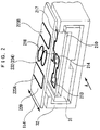
- Fig. 2 shows an outlined positional relation between the scale 210 and the read head 220 in the embodiment.
- the transducer is sliced with a plane normal to the measurement axis 114.
- the scale 210 is located on the beam 31 and the read head 220 is located on the slider 32, opposing to the scale 210.
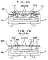
- Fig. 3A shows a cross section of the scale 210 and the read head 220 together with elements for supporting them seen in the A-direction of Fig. 2.
- Fig. 3B shows a conventional example for the purpose of comparison.
- the beam 31 and slider 32 are composed of magnetic stainless steel, for example.
- a substance with a high permeability is layered on the read head 220 in a surface opposite to the scale 210.
- This high permeable substance 33 may employ a high permeable resin composed of high permeable magnetic powders mixed in a resin. In this case, if an IC is mounted on a surface of the read head 220 and the high permeable resin is to be layered on the surface, the high permeable substance 33 can be formed by pouring the resin. If no IC is mounted, a usual magnetic plate or tape may be adhered on that surface of the read head 220.
- the high permeable substance 33 can be arranged on the upper surface of the read head 220. This arrangement allows, as shown in Fig. 3A, the most of magnetic fluxes 34 that are generated from and located in the figure above the magnetic field generator parts 223A and 223B to pass through the high permeable substance 33 that has a low magnetic resistance. Therefore, it is possible to suppress leakage and dispersion of the magnetic fluxes 34 to external and concentrate the magnetic fluxes generated from the magnetic field generator parts 223A and 223B onto the first sections 213, 217 in the coupling loops 212, 216. It is also possible to reduce magnetic resistances in magnetic circuits and increase intensities of signals received at the magnetic flux sensors 232, 234.
- the third and fourth magnetic fields generated from the second sections 214, 218 in the coupling loops 212, 216 are also weaken. Further, the third and fourth magnetic fields diffuse toward above the read head 220 to prevent them from concentrating efficiently on the magnetic flux sensors 232, 234. Accordingly, the magnetic flux sensors 232, 234 can not provide sufficient signal intensities.
- Fig. 4 shows another high permeable substance 35 that is layered on the read head 220 in a surface opposing to the scale 210.
- the high permeable substance 35 may also be layered on the scale 210 in a surface opposing to the read head 220.
- Fig. 5 shows another example of the slider 32, which has an inner frame 36 that may be composed of a non-magnetic metal or resin and an outer frame 37 that may be composed of a magnetic stainless steel.
- the inner frame 36 can prevent magnetic fluxes from diffusing from the beam 31 to the slider 32.
- the outer frame 37 of the slider 32 can magnetically shield external magnetic fields that affect on measurements.
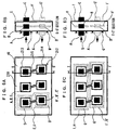
- Figs. 6A-D show 16-way positions A-I and A'-I' to arrange high permeable substances on the scale 210.
- Figs. 6B and 6D are cross-sectional views of Figs. 6A and 6C respectively taken along arrowhead lines S-S' and T-T'.
- the scale 210 is applied to such an induced current position transducer as shown in Fig. 7.
- the transducer comprises a set of magnetic field generator 222 and a set of magnetic flux sensor 224 on the first member or read head 220 and a plurality of coupling loops 212 on the second member or scale 210.
- the arrangement of the high permeable substance shown in Fig. 6 may also be applied to the induced current position transducer shown in Fig. 1.
- the position for arranging the high permeable substance is determined on a path that can be considered ideal for a signal magnetic flux to pass therethrough.
- each coupling loop 212 located inside a scale substrate 41 or on the upper or lower surface thereof.
- A, B, C and A', B', C' are respectively located on extensions of axes of the first sections 213 and the second sections 214.
- E and F exemplify pattern formations of a high permeable substance per coupling loop 212.
- I, H and I', H' exemplify pattern formations of the same first sections 213 and of the same second sections 214 in each coupling loop 212 using common high permeable substances.
- Any one of the above 16-way positions A-I and A'-I' may also be applied to arrange high permeable substances. Any combination of the positions to arrange high permeable substances may be selected in accordance with restrictions such as a design specification for the transducer.
- the magnetic field generator 222 and magnetic flux sensor 224 are located on the read head 220 while the coupling loops 212 on the scale 210.
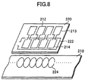
- the magnetic flux sensor 224 may be formed on the scale 210 while the coupling loops 212 and magnetic field generator 222 on the read head 220 as shown in Fig. 8.
- the magnetic flux sensor 224 has a waveform pattern crossing at a certain period and the magnetic field generator 222 has a rectangular pattern formed to cover the second sections 214 in the coupling loops 212.
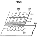
- Fig. 9 shows a further embodiment.
- the magnetic flux sensor 224 is formed on the scale 210 while the coupling loops 212 and magnetic field generator 222 on the read head 220.
- the magnetic flux sensor 224 has a waveform pattern crossing at a certain period and the magnetic field generator 222 has a rectangular pattern formed to cover the first sections 213 in the coupling loops 212.
- the present invention is also applicable to the induced current position transducer thus configured.
- an efficient closed magnetic path is formed between a magnetic field generator and a magnetic flux sensor to reduce occurrence of a harmful leakage magnetic flux and prevent affection from an external magnetic field.
Abstract
Description
- The present invention relates to an induced current position transducer for use in calipers, linear height gauges and linear scales, for example. More particularly, the present invention relates to an induced current position transducer capable of reducing harmful magnetic fluxes diffusing to the outside from the inside of the transducer to improve signal intensity.
- Electric calipers using an induced current position transducer have been developed and demonstrated in the art. In the induced current position transducer, a magnetic field generator generates a primary magnetic field, which couples to a first section in a coupling loop that consists of two loop sections. The first section generates an induced current in response to the primary magnetic field. A second section in the coupling loop generates a secondary magnetic field, corresponding to the induced current, which couples to a magnetic flux sensor. The magnetic flux sensor is arranged at a spatial period that corresponds to an array of coupling loops to provide a signal in accordance with a relative position of the coupling loop to the magnetic flux sensor.
- The above signal processing technology may be applied to a measurement device. In this case, since the measurement device has restrictions from its characteristic on a structure and a structural material, it often employs a metal for the material. If the above technology is applied to a precise measurement under such the condition, it is required to maintain a magnetic flux intensity having a role of a signal with a possible minimal loss. Nevertheless, the primary and secondary magnetic fields diffuse along the members that construct the measurement device. As a result, an efficient magnetic coupling to the coupling loop can not be ensured and a sufficient signal intensity can not be obtained.
- The present invention has been made in consideration of such the disadvantages and according has an object to provide a higher precise measurement technology by preventing harmful diffusion of magnetic fluxes and reducing a signal intensity variation in accordance with a distance (gap) variation between a coupling loop and a magnetic generator and magnetic flux sensor to improve a stability over the gap variation, and by forming a closed magnetic path between the coupling loop and the magnetic generator and magnetic flux sensor to improve the signal intensity.
- The present invention is provided with an induced current position transducer, which comprises a first and a second members arranged opposite to each other and relatively movable along a measurement axis, the first and second members each having a first and a second magnetic flux regions formed normal to the measurement axis; a magnetic field generator for generating a first variable magnetic flux within the first magnetic flux region in response to a driving signal; a coupling loop having a first section located within the first magnetic flux region and a second section located within the second magnetic flux region, the first section generating an induced current in response to the first variable magnetic flux, and the second section generating a second variable magnetic flux corresponding to the induced current; and a magnetic flux sensor disposed within the second magnetic flux region for sensing the second variable magnetic flux, wherein any one of the magnetic field generator, the coupling loop and the magnetic flux sensor is located on one of the first and second members, and the remainder two on the other of the first and second members, and wherein a high permeable substance is disposed on at least a part of the first member, the second member and a gap between the first and second members to form a magnetic path for a flux permeating at least one of the magnetic field generator, the coupling loop and the magnetic flux sensor.
- In a preferred embodiment of the present invention, the magnetic field generator and the magnetic flux sensor are located on one of the first and second members, and the coupling loop on the other of the first and second members.
- In a second embodiment, the magnetic field generator and the coupling loop may be located on one of the first and second members, and the magnetic flux sensor on the other of the first and second members.
- In a third embodiment, the coupling loop and the magnetic flux sensor may be located on one of the first and second members, and the magnetic field generator on the other of the first and second members.
- Preferably, the magnetic flux sensor in the first and second embodiments and the magnetic field generator in the third embodiment have a plurality of regions alternating polarities along the measurement axis, which regions are formed in more detail in a periodic pattern with a certain wavelength along the measurement axis.
- The high permeable substance may comprise a high permeable resin layered on, a magnetic material adhered on, or a magnetic material embedded in at least one of the first and second members.
- The high permeable substance may also comprise a high permeable resin layered on the first member and/or the second member and patterned to cover the pattern of at least one of the magnetic field generator, the coupling loop and the magnetic flux sensor.
- One of the first and second members is secured on a beam extending along the measurement axis, and the other of the first and second members is secured on a slider slidably mounted on the beam. The beam and slider may be composed of a magnetic material.
- In the present invention, one of the first and second members is secured on a beam extending along the measurement axis, and the other of the first and second members is secured on a slider slidably mounted on the beam. Preferably, the beam is composed of a magnetic material, and in the slider at least one side opposite to the beam is composed of a non-magnetic material.
- Other features and advantages of the invention will be apparent from the following description of the preferred embodiments thereof.
- The present invention will be more fully understood from the following detailed description with reference to the accompanying drawings in which:
- Fig. 1 shows an induced current position transducer according to an embodiment of the present invention;
- Fig. 2 is a perspective view showing the same induced current position transducer partly cut off;
- Fig. 3A is a cross-sectional view of Fig. 2 seen in the direction of the arrow A;
- Fig. 3B is a cross-sectional view of a conventional device shown for the purpose of comparison;
- Fig. 4 is a cross-sectional view of a transducer according to another embodiment of the present invention;
- Fig. 5 is a cross-sectional view of a transducer according to a further embodiment of the present invention;
- Figs. 6A-B are a cross-sectional view and a plan view of a scale in a transducer according to a further embodiment of the present invention;
- Figs. 6C-D are a cross-sectional view and a plan view of a scale in a transducer according to a further embodiment of the present invention;
- Fig. 7 is a perspective view showing the main part of the same transducer;
- Fig. 8 is a perspective view showing the main part of a transducer according to a further embodiment of the present invention; and
- Fig. 9 is a perspective view showing the main part of a transducer according to a further embodiment of the present invention.
-
- Preferred embodiments of the present invention will be described below with reference to the accompanying drawings.
- Fig. 1 shows the main part of an incremental, induced current position transducer according to an embodiment of the present invention.
- The
position transducer 200 comprises aread head 220 or a first member and ascale 210 or a second member, which are arranged opposite to each other via a certain gap interposed therebetween and relatively movable along ameasurement axis 114 in the figure. In this embodiment, amagnetic field generator 222, each two sets ofmagnetic flux sensors coupling loops magnetic field generator 222 andmagnetic flux sensors read head 220 and thecoupling loops magnetic field generator 222 andfirst sections coupling loops magnetic flux sensors second sections coupling loops - The
scale 210 includes a plurality offirst coupling loops 212 consisting of closed loops with a first polarity and a plurality ofsecond coupling loops 216 consisting of closed loops with a second polarity. Thecoupling loops 212 are spatially phase-shifted and electrically isolated from thecoupling loops 216. - A
first coupling loop 212 includes afirst section 213 and asecond section 214 connected to each other through a pair ofconnection conductors 215. Asecond coupling loop 216 includes afirst section 217 and asecond section 218 connected to each other through a pair ofconnection conductors 219 in the same manner. - In the plurality of
first coupling loops 212, thefirst sections 213 are arrayed on a first side edge of thescale 210 along themeasurement axis 114. Thesecond sections 214 are arrayed on the center of thescale 210 along themeasurement axis 114. Theconnection conductors 215 extend in the direction normal to themeasurement axis 114 to connect thefirst sections 213 with thesecond sections 214. - In the plurality of
second coupling loops 216, thefirst sections 217 are arrayed on a second side edge of thescale 210 along themeasurement axis 114. Thesecond sections 218 are arrayed on the center of thescale 210 along themeasurement axis 114 and interleaved with thesecond sections 214 of thecoupling loops 212. Theconnection conductors 219 extend in the direction normal to themeasurement axis 114 to connect thefirst sections 217 with thesecond sections 218. - The
read head 220 in the inducedcurrent position transducer 200 includes amagnetic field generator 222 that has afirst part 223A and asecond part 223B of the magnetic field generator. Thefirst part 223A of the magnetic field generator is located at the first side edge of theread head 220 while thesecond part 223B of the magnetic field generator is located at the second side edge of theread head 220. The first 223A and second 223B parts of the magnetic field generator comprise rectangular patterns with a long side that extends along and has the same length as themeasurement axis 114. In addition, the first 223A and second 223B parts of the magnetic field generator have a short side that extends in the direction normal to themeasurement axis 114 and has a length of dl. - The
magnetic field generator 222 hasterminals driving signal generator 150 for transmission. The drivingsignal generator 150 supplies a time-variable driving signal to the magneticfield generator terminal 222A. As a result, a time-variable current can flow from the terminal 222A to the terminal 222B through themagnetic field generator 222. - In response to the above operation, the
first part 223A of the magnetic field generator generates a primary magnetic field that rises up from the sheet of Fig. 1 inside the loop of thefirst part 223A and falls down to the sheet of Fig. 1 outside the loop of thefirst part 223A. To the contrary, thesecond part 223B of the magnetic field generator generates a primary magnetic field that rises up from the sheet of Fig. 1 outside the loop of thesecond part 223B and falls down to the sheet of Fig. 1 inside the loop of thesecond part 223B. As a result, such currents are induced in thecoupling loops - The induced currents flowing into the
first sections parts second sections - For the purpose of maintaining the magnetic flux intensity of the primary and secondary magnetic fields and reducing leakage fluxes to external, a high permeable substance is disposed for the
scale 210 and theread head 220. Positions to locate the substance and effects caused from the location of the substance will be described later in detail. - The read
head 220 includes a first 224 and a second 226 magnetic flux sensors. These first 224 and second 226 magnetic flux sensors respectively consist ofconductor segments conductor segments head 220. - The
segments wires 230 to form positivepolar loops 232 and negativepolar loops 234 alternating in the first 224 and second 226 magnetic flux sensors. As a result, inductive regions are arrayed and formed in a spatially width-modulated periodic pattern. In this case, a pair of adjacent positivepolar loop 232 and negativepolar loop 234 has a length along the measurement axis equal to a wavelength of λ. In addition, a phase difference of λ/4 is defined between the firstmagnetic flux sensor 224 and the secondmagnetic flux sensor 226. The first 224 and second 226 magnetic flux sensors are arranged on the center of the readhead 220 and sandwiched between the first 223A and second 223B parts of the magnetic field generator, having a width of d2 along the direction normal to the measurement axis. - Useless coupling from the magnetic field generator loops to the magnetic flux sensor loops (independent of the position and the scale) can be avoided with such the configuration. The primary magnetic fields generated from the first 223A and second 223B parts of the magnetic field generator direct to opposite directions in the proximity of the first 224 and second 226 magnetic flux sensors. Therefore, the primary magnetic fields cancel one another within occupied areas of the first 224 and second 226 magnetic flux sensors. Ideally, the primary magnetic fields should be cancelled completely in the areas.
- The first 224 and second 226 magnetic flux sensors are inwardly spaced apart a gap of d3 equally from the first 223A and second 223B parts of the magnetic field generator. Therefore, according to the first 223A and second 223B parts of the magnetic field generator, the magnetic fields generated in the areas occupied by the first 224 and second 226 magnetic flux sensors in the
read head 220 are symmetrical and opposite. Direct inductive actions can be thereby cancelled effectively. Voltages induced across the first 224 and second 226 magnetic flux sensors from useless direct coupling with the first 223A and second 223B parts of the magnetic field generator can be reduced first to some extent if the magnetic field generator is spaced from the magnetic flux sensors. Second, a symmetrical design can reduce the useless coupling to zero. - The plural
first coupling loops 212 are arrayed at the same pitch as the wavelength λ of the first 224 and second 226 magnetic flux sensors. Thefirst sections 213 are intended to have a length as close to the wavelength λ as possible along themeasurement axis 114 while ensuring an insulatingspace 201 between adjacent ones. Thefirst sections 213 provide a width of d1 in the direction normal to themeasurement axis 114. - The plural
second coupling loops 216 are similarly arrayed at the same pitch as the wavelength λ. Thefirst sections 217 are intended to have a length as close to the wavelength λ as possible along themeasurement axis 114 while ensuring an insulatingspace 201 between adjacent ones. They provide a width of d1 in the direction normal to themeasurement axis 114. - The
second sections second sections measurement axis 114 that is determined as close to 1/2 the wavelength λ as possible. An insulatingspace 202 is provided between a pair of adjacentsecond sections second sections scale 210. Thesecond sections measurement axis 114. - A gap of d3 is provided between the
second sections first sections read head 220 is located close to thescale 210, thefirst part 223A of the magnetic field generator is arranged in line with thefirst section 213 of thefirst coupling loop 212. Thefirst part 223B of the magnetic field generator is arranged in line with thesecond section 217 of thesecond coupling loop 217. The first 224 and second 226 magnetic flux sensors are arranged in line with thesecond sections - In this embodiment, the
scale 210 and theread head 220 employ printed circuit boards. In addition, the magnetic field generator, coupling loops and magnetic flux sensors are produced with printed circuit board processes. - In measurement operations, a time-variable driving signal is supplied from the driving
signal generator 150 to the terminal 222A of the magnetic field generator. Thefirst part 223A of the magnetic field generator thereby generates a first variable magnetic field in a first direction. Thesecond part 223B generates a second variable magnetic field in a second direction opposite to the first direction. The second variable magnetic field has the same magnetic field intensity as the first variable magnetic field generated from thefirst part 223A of the magnetic field generator. - The plural
first coupling loops 212 couple inductively with thefirst part 223A of the magnetic field generator by means of the first magnetic field generated from thefirst part 223A. An induced current thereby flows clockwise into each of thefirst coupling loops 212. At the same time, the pluralsecond coupling loops 216 couple inductively with thesecond part 223B of the magnetic field generator by means of the second magnetic field generated from the second part 2233. This induces a current flowing counterclockwise into each of thesecond coupling loops 216. As a result, these currents flow in the opposite directions through thesecond sections coupling loops - The clockwise current flowing into the
second section 214 in thefirst coupling loop 212 generates a third magnetic field that falls down to the sheet of Fig. 1 within thesecond section 214. The counterclockwise current flowing into thesecond section 218 in thesecond coupling loop 216 generates a fourth magnetic field that rises up from the sheet of Fig. 1 within thesecond section 218. A net variable magnetic field is thereby created along themeasurement axis 114. This variable magnetic field has a wavelength equal to the wavelength λ of the first 224 and second 226 magnetic flux sensors. - Accordingly, when the positive
polar loops 232 of the firstmagnetic flux sensor 224 meet one of thesecond sections polar loops 234 of the firstmagnetic flux sensor 224 meet the other of thesecond sections polar loops 232 and negativepolar loops 234 of the secondmagnetic flux sensor 226 meet thesecond sections second sections second section 214 are equal to each other and opposite to EMFs generated when they meet thesecond section 218. - Thus, the net output from the positive
polar loop 232 exhibits a sinusoidal function of a position "x" of the readhead 220 along thescale 210 when theread head 220 moves relative to thescale 210. In this function, an offset component in the output signal caused from the useless coupling becomes nominal zero. Similarly, the net output from the negativepolar loop 234 exhibits a sinusoidal function of the position "x" of the readhead 220 along thescale 210 when theread head 220 moves relative to thescale 210. In this function, an offset component in the output signal caused from the useless coupling becomes nominal zero. EMF contributions are provided in the same phase from the positivepolar loop 232 and the negativepolar loop 234. - The first 224 and second 226 magnetic flux sensors are in a quadrature relation. Therefore, the output signal obtained at the first
magnetic flux sensor 224 as the function of the position x has a phase difference of 90° from the output signal obtained at the secondmagnetic flux sensor 226 as the function of the position x. These signals are both sent to asignal process circuit 140 for processing received signals. - From the first 224 and second 226 magnetic flux sensors, the
signal process circuit 140 reads in the output signals, which are sampled, converted into digital values and then sent to acontrol unit 160. Thecontrol unit 160 processes the digitized output signals to determine the relative position x of the readhead 220 to thescale 210 within the wavelength λ. - It should be appreciated that an appropriate variation on the locations of the through wires can give a zero width in the direction normal to the measurement axis to one of the positive
polar loops 232 and negative polar loops 234 (effecting as simple conductor elements between adjacent loops). In this case, the first 224 and second 226 magnetic flux sensors serve as single-polar magnetic flux receivers, which have increased sensitivities to an external magnetic field and provide output signals with 1/2 amplitude (resulted from reduction of the loop region) compared to the previous embodiment. - This design modification can provide some benefits. As a result of the magnetic field generator symmetrically configured, the useless magnetic fluxes through loops are held at nominal zero. The output signals from the
magnetic flux sensors - On the basis of properties of quadrature outputs from the first 224 and second 226 magnetic flux sensors, the
control unit 160 can determine the direction of relative movement of the readhead 220 to thescale 210. Thecontrol unit 160 counts part or all of "increments" of the wavelength λ passing through. Thecontrol unit 160 employs the count and the relative position within the wavelength λ to provide a relative position from a certain origin located between the readhead 220 and thescale 210. Thecontrol unit 160 sends a control signal to thedriving signal generator 150, which generates the time-variable driving signal. - Fig. 2 shows an outlined positional relation between the
scale 210 and theread head 220 in the embodiment. For the convenience of simplification, the transducer is sliced with a plane normal to themeasurement axis 114. - A
beam 31, extending along the measurement axis, supports aslider 32 slidably. Thescale 210 is located on thebeam 31 and theread head 220 is located on theslider 32, opposing to thescale 210. - Fig. 3A shows a cross section of the
scale 210 and theread head 220 together with elements for supporting them seen in the A-direction of Fig. 2. Fig. 3B shows a conventional example for the purpose of comparison. - The
beam 31 andslider 32 are composed of magnetic stainless steel, for example. A substance with a high permeability is layered on theread head 220 in a surface opposite to thescale 210. This highpermeable substance 33 may employ a high permeable resin composed of high permeable magnetic powders mixed in a resin. In this case, if an IC is mounted on a surface of the readhead 220 and the high permeable resin is to be layered on the surface, the highpermeable substance 33 can be formed by pouring the resin. If no IC is mounted, a usual magnetic plate or tape may be adhered on that surface of the readhead 220. - The high
permeable substance 33 can be arranged on the upper surface of the readhead 220. This arrangement allows, as shown in Fig. 3A, the most ofmagnetic fluxes 34 that are generated from and located in the figure above the magneticfield generator parts permeable substance 33 that has a low magnetic resistance. Therefore, it is possible to suppress leakage and dispersion of themagnetic fluxes 34 to external and concentrate the magnetic fluxes generated from the magneticfield generator parts first sections coupling loops magnetic flux sensors - To the contrary, in the conventional induced current position transducer shown in Fig. 3B, no magnetic material is connected to a surface of the read
head 220. In addition, an inner frame of theslider 32 is composed of a magnetic metal. Accordingly, flows of themagnetic fluxes 34 can not form a closed magnetic circuit that passes through the surface of the readhead 220 effectively, resulting in diffusion of themagnetic fluxes 34 toward above the readhead 220. As a result, the magnetic fluxes from the magneticfield generator parts first sections coupling loops second sections coupling loops head 220 to prevent them from concentrating efficiently on themagnetic flux sensors magnetic flux sensors - It is more effective if a high permeable substance exists between the read
head 220 and thescale 210. Fig. 4 shows another highpermeable substance 35 that is layered on theread head 220 in a surface opposing to thescale 210. The highpermeable substance 35 may also be layered on thescale 210 in a surface opposing to the readhead 220. - Fig. 5 shows another example of the
slider 32, which has aninner frame 36 that may be composed of a non-magnetic metal or resin and anouter frame 37 that may be composed of a magnetic stainless steel. According to such the arrangement, theinner frame 36 can prevent magnetic fluxes from diffusing from thebeam 31 to theslider 32. In addition, theouter frame 37 of theslider 32 can magnetically shield external magnetic fields that affect on measurements. - Figs. 6A-D show 16-way positions A-I and A'-I' to arrange high permeable substances on the
scale 210. Figs. 6B and 6D are cross-sectional views of Figs. 6A and 6C respectively taken along arrowhead lines S-S' and T-T'. - The
scale 210 is applied to such an induced current position transducer as shown in Fig. 7. The transducer comprises a set ofmagnetic field generator 222 and a set ofmagnetic flux sensor 224 on the first member or readhead 220 and a plurality ofcoupling loops 212 on the second member orscale 210. The arrangement of the high permeable substance shown in Fig. 6 may also be applied to the induced current position transducer shown in Fig. 1. - Desirably, as shown with arrows in the figure, the position for arranging the high permeable substance is determined on a path that can be considered ideal for a signal magnetic flux to pass therethrough.
- For the above reason, a high permeable substance characteristically exists corresponding to each
coupling loop 212 located inside ascale substrate 41 or on the upper or lower surface thereof. In particular, A, B, C and A', B', C' are respectively located on extensions of axes of thefirst sections 213 and thesecond sections 214. - E and F exemplify pattern formations of a high permeable substance per
coupling loop 212. I, H and I', H' exemplify pattern formations of the samefirst sections 213 and of the samesecond sections 214 in eachcoupling loop 212 using common high permeable substances. Any one of the above 16-way positions A-I and A'-I' may also be applied to arrange high permeable substances. Any combination of the positions to arrange high permeable substances may be selected in accordance with restrictions such as a design specification for the transducer. - The more the positions for arranging high permeable substances exist, the more the effect by the positions becomes sufficient to increase the signal intensity and reduce the leakage flux.
- In the above embodiment, the
magnetic field generator 222 andmagnetic flux sensor 224 are located on theread head 220 while thecoupling loops 212 on thescale 210. Themagnetic flux sensor 224 may be formed on thescale 210 while thecoupling loops 212 andmagnetic field generator 222 on theread head 220 as shown in Fig. 8. In this case, themagnetic flux sensor 224 has a waveform pattern crossing at a certain period and themagnetic field generator 222 has a rectangular pattern formed to cover thesecond sections 214 in thecoupling loops 212. - Fig. 9 shows a further embodiment. In this embodiment, the
magnetic flux sensor 224 is formed on thescale 210 while thecoupling loops 212 andmagnetic field generator 222 on theread head 220. In this case, themagnetic flux sensor 224 has a waveform pattern crossing at a certain period and themagnetic field generator 222 has a rectangular pattern formed to cover thefirst sections 213 in thecoupling loops 212. The present invention is also applicable to the induced current position transducer thus configured. - As obvious from the forgoing, according to the present invention, an efficient closed magnetic path is formed between a magnetic field generator and a magnetic flux sensor to reduce occurrence of a harmful leakage magnetic flux and prevent affection from an external magnetic field. This leads to an induced current position transducer capable of improving signal intensity and achieving a higher precise measurement.
- Having described the embodiments consistent with the present invention, other embodiments and variations consistent with the invention will be apparent to those skilled in the art. Therefore, the invention should not be viewed as limited to the disclosed embodiments but rather should be viewed as limited only by the spirit and scope of the appended claims.
Claims (7)
- An induced current position transducer (200), which comprises:a first (220) and a second (210) members arranged opposite to each other and relatively movable along a measurement axis (114), which first and second members each have a first and a second magnetic flux regions formed normal to said measurement axis;a magnetic field generator (222) for generating a first variable magnetic flux within said first magnetic flux region in response to a driving signal;a coupling loop (212, 216) having a first section (213, 217) located within said first magnetic flux region and a second section (214, 218) located within said second magnetic flux region, which first section (213, 217) generates an induced current in response to said first variable magnetic flux, and which second section (214, 218) generates a second variable magnetic flux corresponding to said induced current; anda magnetic flux sensor (224, 226) disposed within said second magnetic flux region for sensing said second variable magnetic flux, wherein any one of said magnetic field generator (222), said coupling loop (212, 216) and said magnetic flux sensor (224, 226) is located on one of said first (220) and second (210) members, and the remainder two on the other of said first (220) and second (210) members, characterized in that a high permeable substance (33, 35) is disposed on at least a part of said first member (220), said second member (210) and a gap between said first (220) and second (210) members to form a magnetic path for a flux to permeating at least one of said magnetic field generator (222), said coupling loop (212, 216) and said magnetic flux sensor (224, 226).
- The induced current position transducer (200) according to claim 1, characterized in that said high permeable substance (33, 35) comprises a high permeable resin layered on at least one of said first (220) and second (210) members.
- The induced current position transducer (200) according to claim 1 or 2, characterized in that said high permeable substance (33, 35) comprises a magnetic material adhered on at least one of said first (220) and second (210) members.
- The induced current position transducer (200) according to any one of claims 1-3, characterized in that said high permeable substance (33, 35) comprises a magnetic material embedded in at least one of said first (220) and second (210) members.
- The induced current position transducer (200) according to claim 1, characterized in that said high permeable substance comprises (33, 35) a high permeable resin layered on said first member (220) and/or said second member (210) and patterned to cover the pattern of at least one of said magnetic field generator (222), said coupling loop (212, 216) and said magnetic flux sensor (224, 226).
- The induced current position transducer (200) according to any one of claims 1-5, characterized in that one of said first (220) and second (210) members is secured on a beam (31) extending along said measurement axis (114), and the other of said first (220) and second (210) members is secured on a slider (32) slidably mounted on said beam, said beam (31) and slider (32) composed of a magnetic material.
- The induced current position transducer (200) according to any one of claims 1-5, characterized in that one of said first (220) and second (210) members is secured on a beam (31) extending along said measurement axis (114), and the other of said first (220) and second (210) members is secured on a slider (32) slidably mounted on said beam (31), said beam (31) composed of a magnetic material, and in said slider (32) at least one side (36) opposite to said beam (31) composed of a non-magnetic material.
Applications Claiming Priority (2)
| Application Number | Priority Date | Filing Date | Title |
|---|---|---|---|
| JP2000198895 | 2000-06-30 | ||
| JP2000198895A JP3559225B2 (en) | 2000-06-30 | 2000-06-30 | Dielectric type position detector |
Publications (2)
| Publication Number | Publication Date |
|---|---|
| EP1174687A2 true EP1174687A2 (en) | 2002-01-23 |
| EP1174687A3 EP1174687A3 (en) | 2006-04-19 |
Family
ID=18696993
Family Applications (1)
| Application Number | Title | Priority Date | Filing Date |
|---|---|---|---|
| EP01115812A Withdrawn EP1174687A3 (en) | 2000-06-30 | 2001-06-28 | Induced current position transducer |
Country Status (4)
| Country | Link |
|---|---|
| US (1) | US6531866B2 (en) |
| EP (1) | EP1174687A3 (en) |
| JP (1) | JP3559225B2 (en) |
| CN (1) | CN1173150C (en) |
Families Citing this family (18)
| Publication number | Priority date | Publication date | Assignee | Title |
|---|---|---|---|---|
| DE10259618A1 (en) * | 2002-12-18 | 2004-07-08 | Tesa Ag | Adhesive tape for protecting, labeling, isolating and wrapping |
| US7191759B2 (en) * | 2004-04-09 | 2007-03-20 | Ksr Industrial Corporation | Inductive sensor for vehicle electronic throttle control |
| US7292026B2 (en) * | 2005-04-08 | 2007-11-06 | Ksr International Co. | Signal conditioning system for inductive position sensor |
| US7449878B2 (en) * | 2005-06-27 | 2008-11-11 | Ksr Technologies Co. | Linear and rotational inductive position sensor |
| JP5252297B2 (en) * | 2009-03-13 | 2013-07-31 | 株式会社リコー | Toner supply device and image forming apparatus |
| CN102840821A (en) * | 2011-06-24 | 2012-12-26 | 上海雷尼威尔测量技术有限公司 | Displacement sensor |
| JP6188433B2 (en) * | 2013-06-07 | 2017-08-30 | 浜松ホトニクス株式会社 | Solid-state imaging device |
| US9733317B2 (en) * | 2014-03-10 | 2017-08-15 | Dmg Mori Seiki Co., Ltd. | Position detecting device |
| TWI582924B (en) * | 2016-02-02 | 2017-05-11 | 宏碁股份有限公司 | Heat dissipation module and electronic device |
| US10775199B2 (en) * | 2016-08-24 | 2020-09-15 | Mitutoyo Corporation | Winding and scale configuration for inductive position encoder |
| US10520335B2 (en) * | 2016-08-24 | 2019-12-31 | Mitutoyo Corporation | Winding configuration for inductive position encoder |
| US10612943B2 (en) * | 2016-08-24 | 2020-04-07 | Mitutoyo Corporation | Winding and scale configuration for inductive position encoder |
| US9927261B1 (en) * | 2016-09-23 | 2018-03-27 | Sagentia Ltd. | Inductive sensor device for use with a distance measurement device |
| JP7086469B2 (en) * | 2018-05-09 | 2022-06-20 | 株式会社ミツトヨ | Electromagnetic induction encoder |
| US11169008B2 (en) | 2020-03-23 | 2021-11-09 | Mitutoyo Corporation | Transmitter and receiver configuration for inductive position encoder |
| US11181395B2 (en) | 2020-03-23 | 2021-11-23 | Mitutoyo Corporation | Transmitter and receiver configuration for inductive position encoder |
| US11067414B1 (en) | 2020-03-23 | 2021-07-20 | Mitutoyo Corporation | Transmitter and receiver configuration for inductive position encoder |
| US11713983B2 (en) | 2021-06-30 | 2023-08-01 | Mitutoyo Corporation | Sensing winding configuration for inductive position encoder |
Citations (4)
| Publication number | Priority date | Publication date | Assignee | Title |
|---|---|---|---|---|
| US5285154A (en) * | 1991-10-15 | 1994-02-08 | Eldec Corporation | Saturable core proximity sensor aligned perpendicular to a magnet target having a plate and a non-magnetic metal housing |
| WO1998054734A1 (en) * | 1997-05-26 | 1998-12-03 | Kureha Kagaku Kogyo K.K. | Resin composition |
| US5901458A (en) * | 1997-11-21 | 1999-05-11 | Mitutoyo Corporation | Electronic caliper using a reduced offset induced current position transducer |
| US6049204A (en) * | 1997-11-21 | 2000-04-11 | Mitutoyo Corporation | Electronic linear scale using a reduced offset high accuracy induced current position transducer |
Family Cites Families (1)
| Publication number | Priority date | Publication date | Assignee | Title |
|---|---|---|---|---|
| US5351004A (en) * | 1991-10-15 | 1994-09-27 | Eldec Corporation | Saturable core proximity sensor including a flux director and a magnetic target element |
-
2000
- 2000-06-30 JP JP2000198895A patent/JP3559225B2/en not_active Expired - Fee Related
-
2001
- 2001-06-28 US US09/892,441 patent/US6531866B2/en not_active Expired - Lifetime
- 2001-06-28 EP EP01115812A patent/EP1174687A3/en not_active Withdrawn
- 2001-06-29 CN CNB011243260A patent/CN1173150C/en not_active Expired - Fee Related
Patent Citations (4)
| Publication number | Priority date | Publication date | Assignee | Title |
|---|---|---|---|---|
| US5285154A (en) * | 1991-10-15 | 1994-02-08 | Eldec Corporation | Saturable core proximity sensor aligned perpendicular to a magnet target having a plate and a non-magnetic metal housing |
| WO1998054734A1 (en) * | 1997-05-26 | 1998-12-03 | Kureha Kagaku Kogyo K.K. | Resin composition |
| US5901458A (en) * | 1997-11-21 | 1999-05-11 | Mitutoyo Corporation | Electronic caliper using a reduced offset induced current position transducer |
| US6049204A (en) * | 1997-11-21 | 2000-04-11 | Mitutoyo Corporation | Electronic linear scale using a reduced offset high accuracy induced current position transducer |
Also Published As
| Publication number | Publication date |
|---|---|
| CN1334437A (en) | 2002-02-06 |
| JP2002013905A (en) | 2002-01-18 |
| US6531866B2 (en) | 2003-03-11 |
| CN1173150C (en) | 2004-10-27 |
| US20020008510A1 (en) | 2002-01-24 |
| JP3559225B2 (en) | 2004-08-25 |
| EP1174687A3 (en) | 2006-04-19 |
Similar Documents
| Publication | Publication Date | Title |
|---|---|---|
| US6531866B2 (en) | Induced current position sensor having a closed magnetic path | |
| EP2085751B1 (en) | Electromagnetic Induction Type Encoder | |
| CN110657826B (en) | Scale structure for inductive position encoder | |
| US6011389A (en) | Induced current position transducer having a low power electronic circuit | |
| US6329813B1 (en) | Reduced offset high accuracy induced current absolute position transducer | |
| US6646433B2 (en) | Induced current position transducers using tape scales with apertures | |
| US6259249B1 (en) | Induction-type position measuring apparatus | |
| JP4944292B2 (en) | Position detector with position-dependent amplitude encoding | |
| US7365535B2 (en) | Closed-loop magnetic sensor system | |
| JP4615955B2 (en) | Inductive displacement detector | |
| US11067647B2 (en) | Low-noise magnetoresistive sensor having multi-layer magnetic modulation structure | |
| JPH054307U (en) | Magnetic sensor | |
| EP1014041B1 (en) | Inductive position transducer having high accuracy and reduced offset | |
| JPS63191069A (en) | Current detector | |
| US6720760B2 (en) | Induced current position transducers having improved scale loop structures | |
| US11169008B2 (en) | Transmitter and receiver configuration for inductive position encoder | |
| US20220205814A1 (en) | Sensing winding configuration for inductive position encoder | |
| JP2005077150A (en) | Induction type position detector | |
| EP3803277A1 (en) | Linear position sensor | |
| JPH0368872A (en) | Current detector | |
| JPH0754333B2 (en) | Current detection unit | |
| JPH02195268A (en) | Unit for sensing current |
Legal Events
| Date | Code | Title | Description |
|---|---|---|---|
| PUAI | Public reference made under article 153(3) epc to a published international application that has entered the european phase |
Free format text: ORIGINAL CODE: 0009012 |
|
| AK | Designated contracting states |
Kind code of ref document: A2 Designated state(s): AT BE CH CY DE DK ES FI FR GB GR IE IT LI LU MC NL PT SE TR |
|
| AX | Request for extension of the european patent |
Free format text: AL;LT;LV;MK;RO;SI |
|
| PUAL | Search report despatched |
Free format text: ORIGINAL CODE: 0009013 |
|
| AK | Designated contracting states |
Kind code of ref document: A3 Designated state(s): AT BE CH CY DE DK ES FI FR GB GR IE IT LI LU MC NL PT SE TR |
|
| AX | Request for extension of the european patent |
Extension state: AL LT LV MK RO SI |
|
| 17P | Request for examination filed |
Effective date: 20060620 |
|
| 17Q | First examination report despatched |
Effective date: 20060914 |
|
| AKX | Designation fees paid |
Designated state(s): DE FR GB IT |
|
| STAA | Information on the status of an ep patent application or granted ep patent |
Free format text: STATUS: THE APPLICATION IS DEEMED TO BE WITHDRAWN |
|
| 18D | Application deemed to be withdrawn |
Effective date: 20120103 |