FIELD OF THE INVENTION
-
The present invention relates to the treatment of vascular disease during
either surgery or percutaneous angioplasty and stenting. More particularly, the
invention relates to a system that reduces macro- and micro-embolization
during the treatment of vascular stenosis.
BACKGROUND OF THE INVENTION
-
A variety of surgical and non-surgical procedures have been developed
for removing obstructions from blood vessels. Balloon angioplasty utilizes a
balloon-tipped catheter which may be inserted within a stenosed region of the
blood vessel. By inflation of the balloon, the stenosed region is dilated.
Surgery involves either removing the plaque from the artery or attaching a graft
to the artery so as to bypass the obstructing plaque. Other techniques, such as
atherectomy, have also been proposed. In atherectomy, a rotating blade is
used to shave plaque from an arterial wall.
-
One problem common with all of these techniques is the accidental
release of portions of the plaque or thrombus, resulting in emboli which can
lodge elsewhere in the vascular system. Such emboli are extremely dangerous
to the patient, frequently causing severe impairment of the distal circulatory
bed. Depending upon the vessel being treated, this may result in stroke,
myocardial infarction or limb ischemia.
-
During a postoperative period vascular filters are used, when there is a
perceived risk of the patient encountering a pulmonary embolus resulting from
the lots generated at the surgical site. As a typical use of vascular filters, the
filter is mounted in the vena cava to catch large emboli passing from the
surgical site to the lungs.
-
Permanent implantation of a filter is often medically undesirable, yet it
has been done because vascular filters are implanted in patients primarily in
response to potentially life threatening situations. Accordingly, permanent
implantation of a vascular filter is often accepted.
-
Nonetheless, avoid permanent implantation, it would be desirable to
provide an apparatus and method for preventing embolization associated with
conventional surgery and angioplasty procedures. In particular, it would be
desirable to provide a device which could be located within the vascular system
to collect and retrieve portions of plaque and thrombus which have dislodged
during the surgery or angioplasty procedure.
OBJECT OF THE INVENTION
-
This invention provides a vascular filter system for reducing macro- and
micro-embolization.
-
It also provides a vascular filter system which is readily removable from
the vascular system of a patient when the filter is no longer needed.
-
Further, it provides a vascular filter system having a configuration which
does not require hooks to penetrate and grip the blood vessel walls, so that
filter deployment results in less blood vessel injury.
-
Further the invention provides a vascular filter system of very low profile
which is delivered along a guidewire and can be used in small vessels.
-
The invention will become more readily apparent from the description
below.
SUMMARY OF THE INVENTION
-
The present invention generally relates to a vascular filter system useful
in the treatment of vascular disease, in particular, a percutaneous angioplasty
and stenting system useful, for example, in the treatment of carotid arterial
stenoses. Macro- and micro-embolization occurs during such angioplasties,
which increases the risk of stroke. The system of the present invention is
useful in preventing such risk. This system is also useful in any procedure in
which embolization is a risk.
-
The vascular filter system of the present invention decreases embolic
events while allowing distal tissue perfusion. The filter is incorporated into a
guidewire which is used during the entire procedure, from first crossing of a
lesion through deploying a stent. In one embodiment, the filter consists of a thin
membrane attached to the guidewire and supported by fine metal spines.
Attachment of filter to guidewire allows membrane expansion, to provide a firm
fit inside the artery. Also, the system allows collapse of the filter membrane at
the end of the procedure, so that it fits tightly against the guidewire and is
withdrawn through the guide catheter.
-
In another embodiment, the membrane rests upon or is attached to a
basket-like structure, at least one end of which is attached to the guidewire.
The membrane has a pore size such that blood flow is not impeded when the
filter membrane is expanded, but through which micro- and macro-emboli are
blocked. Expansion of the filter membrane is aided by the forward flow of blood
against the filter. The filter design results in a very low profile so that the initial
crossing of the lesion via the guidewire is minimally traumatic. Also, small
diameter and narrow profile facilitate use of the device in smaller or larger
arteries with minimal or no obstruction of blood flow.
-
Further embodiments of this filter membrane and its deployment system
are provided without departing from the general nature of the guidewire based
system. Among those are various modifications of the folding made to the filter
membrane, and its configuration.
BRIEF DESCRIPTION OF THE DRAWINGS
-
The above advantages of the invention will be apparent upon
consideration of the following detailed description, taken in conjunction with the
accompanying drawings. In these drawings, reference characters refer to like
parts throughout.
- Fig. 1 is a lateral, partial cross-sectional view of the distal end of a
guidewire of one embodiment of the invention, with the filter membrane in a
collapsed position;
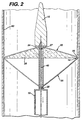
- Fig. 2 is a lateral, partial cross-sectional view of the distal end of a
guidewire of Fig. 1 with the filter membrane in an expanded, deployed position;
- Fig. 3 is a proximal end-on view of the filter membrane shown in Fig. 2;
- Fig. 4 is a lateral, partial cross-sectional view of another embodiment of
the invention;
- Fig. 5A is a lateral, partial cross-sectional view of a further embodiment
of the invention;
- Fig. 5B is a lateral, partial cross-sectional view of the embodiment of the
invention shown in Fig. 5A with the filter membrane in an expanded, deployed
position;
- Fig. 6 is a partial cross-sectional view of a control handle for the
invention;
- Fig. 7 is a partial cross-sectional view of another embodiment of the
invention;
- Fig. 8 is a partial cross-sectional view of an embodiment of the invention
in which the filter membrane has curved supports;
- Fig. 9 is a partial cross-sectional view of yet another embodiment of the
invention in which the filter membrane has a spiral wire;
- Fig. 10 is a top cross-sectional view of the embodiment of the invention
shown in Fig. 9;
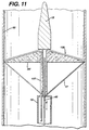
- Fig. 11 is a partial cross-sectional view of another embodiment of the
invention having inflatable support spines;
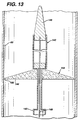
- Fig. 12 and 13 represent partial cross-sectional views of another
embodiment of the invention in collapsed and deployed positions, respectively;
- Fig. 14 is a lateral, partial cross-sectional view of one embodiment of the
invention with the filter membrane in an open position;
- Fig. 15 is a lateral, partial cross-sectional view of the embodiment of the
invention in Fig. 14 with the sheath closed;
- Fig. 16 is a schematic representation of a portion of a filter membrane
according to the invention;
- Fig. 17 is a lateral view of a core wire useful according to the invention;
- Fig. 18 is a cross-sectional view across line 18-18 of a portion of the
core wire of Fig. 17;
- Fig. 19 is a lateral, cross-sectional view of an alternative basket structure
for the embodiment of Fig. 14;
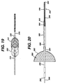
- Fig. 20 is a lateral, partial cross-sectional view of another embodiment of
the invention;
- Fig. 21 is a lateral, partial cross-sectional view of a further embodiment
of the invention;
- Fig. 22 is a schematic, partial cross-sectional view of another
embodiment of the invention where the distal section of the filter basket is
inverted;
- Fig. 23 is a schematic, partially cross-sectional view of the embodiment
shown in Fig. 22 where the filter basket is collapsed;
- Figs. 24, 25, 26 and 27 are schematic views of other modifications of the
present invention;
- Figs. 28, 29, 30 and 31 are schematic elevation views of an alternate
capture mechanism of the sheath of the present invention; and
- Figures 32a and 32b are plan views of an alternate embodiment of the
embolic capture guidewire system of the present invention.
-
DETAILED DESCRIPTION OF THE INVENTION
-
The present invention relates to a vascular filter system for use in
percutaneous angioplasty and stenting and provides for the prevention of distal
embolism during endovascular procedures. Further, the filter system of the
invention allows for distal perfusion while preventing embolization.
-
The system comprises a thin, perforated filter membrane which is
capable of blocking emboli and which is attached to the distal end of a
guidewire. In one embodiment the system uses thin fibers which are moveable
and are attached to or encapsulated by the filter membrane to deploy and /or
collapse the filter membrane. The invention also contemplates the use of metal
spines or inflatable spines attached to the filter membrane to deploy the filter
membrane. The fibers or spines can also be attached to a moveable core
which is slidable within the guidewire and is used to deploy and collapse the
filter membrane.
-
The filter membrane deploys in an umbrella-like fashion with the
unattached edge of the membrane moving upward, i.e., distally, and outward
until it is in firm contact with an artery wall. When the filter membrane is
deployed, it spans the cross-sectional area of the vessel lumen being treated
for a stenosis such as carotid stenosis, or another condition likely to produce
emboli.
-
In another, preferred embodiment of the invention, a thin, flexible,
perforated membrane is supported by four or more supports that form a distally
extending basket. At least one end of the basket is attached to the guidewire,
and the other, slidable end can be moved to cause the membrane to open or
close.
-
The invention can be appreciated by reference to the drawings. Fig. 1
illustrates a lateral, cross-sectional view of a distal end of a guidewire 10 with a
filter membrane 20 attached thereto. Fig. 1 shows guidewire 10 with a
shapeable, tapered soft tip 15 at its extreme distal end which provides flexibility
and maneuverability to guidewire 10. The filter membrane in Fig. 1 is in a
collapsed position. Filter membrane 20 has a fixed portion 24 which is
movably attached to guidewire 10, and filter membrane 20 lies adjacent
guidewire 10 proximal to fixed portion 24 when filter membrane 20 is in the
collapsed state. A moveable core 40 runs through a center lumen 11 of
guidewire 10 and preferably extends distally a short distance beyond fixed
portion 24 of filter membrane 20. Deploying wires or fibers 30 are each firmly
attached at one end 27 to moveable core 40 distal to fixed portion 21 of filter
membrane 20. The deploying fibers 30 are attached at their other ends to filter
membrane 20 at attachment points 22.
-
Collapsing fibers 35 are each firmly attached at one end 12 to the
portion of moveable core wire 40 which is interior to filter membrane 20 when it
is in the collapsed state. Collapsing fibers 35 are each attached at their other
end 13 to filter membrane 20 at attachment points 22. Accordingly, collapsing
fibers 35 lie interior to filter membrane 20 when filter membrane 20 is in the
collapsed state.
-
Filter membrane 20 is deployed when the operator pulls moveable core
40 proximally through the interior of guidewire 10. Prior to retraction of
moveable core 40, deploying fibers 30 are sufficiently relaxed so as not to
create any tension at filter membrane attachment points 22. Upon retraction of
moveable core 40, tension is created in deploying fibers 30.
-
There will preferably be from 2 to 6 evenly-spaced deploying fibers 30
and collapsing fibers 35, with 3 or 4 such fibers 30, 35 being most preferred.
The deploying fibers 30 and collapsing fibers 35 can be made of any flexible,
medically acceptable material, including stainless steel, nitinol, another metal or
metallic alloy, a non-metallic substance such as graphite, or a suitable polymer.
In addition, guidewire 10 and moveable core 40 can be made from similar
materials. Typically, guidewire 10 has an external diameter of from about 0.014
in. to about 0.035 in., a wall thickness between about 0.002 in. to about 0.010
in., and a length between about 25 cm to about 300 cm. Also, moveable core
40 could have a diameter of from about 0.003 in. to about 0.010 in. and a length
of from about 30 cm to about 350 cm.
-
Fig. 2 illustrates the filter device of the invention in a deployed position
on the inside of an artery wall 60. Moveable core 40 is in a retracted state, i.e.,
pulled proximally through the interior of guidewire 10. Tension is created in
deploying fibers 30, and filter membrane 20 extends to a deployed position,
where the outer edge 14 of filter membrane 20 contacts artery wall 60. In this
deployed position, collapsing fibers 35 are in a relaxed state and extend from
filter membrane attachment points 22 to fixed attachment points 28 on
moveable core 40.
-
The flow of blood in Fig. 2 is toward the distal end of guidewire 10. As
such, the force of the flow of blood pushed on deployed filter membrane 20 and
helps to maintain filter membrane 20 in the deployed position.
-
For withdrawal of guidewire 10 and the filter device, filter membrane 20
is collapsed so that it sits tightly against guidewire 10. This is accomplished by
extending moveable core 40 distally through guidewire 10, thus relaxing
deploying fibers 30 and creating tension in collapsing fibers 35. The tension in
collapsing fibers 35 collapses the filter membrane 20, allowing it to fit tightly
against guidewire 10 in the recess 16, as depicted in Fig. 1.
-
Fig. 3 illustrates the filter device of the invention from a distal end view in
Fig. 2, with filter membrane 20 deployed. Guidewire 10 is centrally located, and
structural wires 50 are seen extending from guidewire 10 to the outer edge 14
of filter membrane 20. These wires 50 provide structural integrity and rigidity to
filter membrane 20. Fig. 3 depicts four, evenly-spaced structural wires 50, but
there can be more or less structural wires 50. Preferably there are from two to
six structural wires 50. The wires 50 may preferably be made of stainless steel
or another medically acceptable metal or alloy.
-
Filter membrane 20 of the invention is preferably a mesh such as that
depicted in Fig. 3. The mesh should have pores of a size sufficient to block and
capture any micro- and macro-emboli which may flow downstream from the site
where the stenosis is being treated, but large enough such that blood flow is not
impeded. The mesh used in the filter device of the invention can have a pore
size less than 300 microns, preferably from about 50 to about 150 microns.
Moreover, the distance from guidewire 10 to free ends 22 allows a firm fit
between filter membrane 20 and artery wall 60. The diameter of filter
membrane 20 will be directly related to the artery being treated, with typical
diameters ranging from less than about 2 mm to about 40 mm, most preferably
from about 2 mm to about 20 mm.
-
The membrane can be comprised of fabric or non-fabric meshes, such
as those used in known hemodialysis filters or heart-lung bypass machine
filters. Suitable materials include polymers or physiologically acceptable metals
or alloys.
-
In alternative embodiments of the invention seen in Figs. 4, 5A and 5B,
filter membrane 20 is suspended between from two to eight, preferably from
four to eight, thin metal wires 51 which serve as spines for filter membrane 20.
Wires 51 may be comprised of stainless steel or another metallic alloy, nitinol,
or another shape-memory material. Wires 51 are constructed so that they
assume a 90° angle with guidewire 10 when they are in an unconstrained state.
This will result in expansion of the filter membrane 20 to a position normal to
guidewire 10. A set of thin fibers 17 are attached at attachment points 18 to
filter membrane outer edge 14 and are used to collapse filter membrane 20.
-
Fig. 4 shows an embodiment of this invention in which metal wires 51
are allowed to regain their unconstrained 90° angle state by use of a moveable
core 40 that runs through guidewire 10. Prior to retraction of moveable core 40,
fibers 17b are sufficiently tensed so as to restrain wires 51. Upon retraction of
moveable core 40, tension in fibers 17 is released and wires 51 are allowed to
revert to their relaxed shape, which will result in expansion of filter membrane
20 to a position normal to guidewire 10.
-
Figs. 5A and 5B show an embodiment of the invention wherein wires 51
are restrained by fibers 17 that run through guidewire 10 and that are controlled
at a remote location. In Fig. 5A, there is sufficient tension in fibers 17 to
maintain wires 51 in a constrained position. In Fig. 5B, tension in fibers 17 has
been relaxed such that wires 51 are allowed to revert to their relaxed shape,
which will result in expansion of filter membrane 20 to a position normal to
guidewire 10.
-
Fig. 6 depicts a control handle especially suitable for the embodiment of
the invention shown in Figs. 5A and 5B. The proximal end 32 of guidewire 10 is
rotatably attached to handle 33, such that rotation causes handle 33 to move
relative to proximal guidewire end 32. For example, handle 33 may have
threads 34 which engage threads 35 on guidewire proximal end 32. Fibers 17
attached to filter membrane 20 are secured in a base 36 of handle 33. Then, as
handle 33 is turned, the fibers 17 move distally or proximally to open or close
filter membrane 20.
-
As handle 31 is turned clockwise in the direction of arrow A and fibers 17
are allowed to move distally in the direction of arrow C, the tension on the filter
membrane fibers 17 decreases, and wires 51 are allowed to assume their
natural 90° angle with respect to the guidewire, resulting in opening of filter
membrane 20. Similarly, when handle 33 is turned counter-clockwise is the
direction of arrow D, the tension on filter fibers 17 increases, causing filter
membrane 20 to collapse tightly against guidewire 10. Of course, the direction
of turn of handle 33 as discussed above can be reversed, as long as threads
34, 35 are properly formed to allow appropriate movement of handle 33 relative
to guidewire proximal end 32.
-
In yet another embodiment of the invention shown in Fig. 11, filter
membrane 20 can be supported by inflatable spines 135 supporting the filter
membrane 20. Spines 135 supporting the filter membrane 20 are from two to
six hollow plastic tubes which are inflatable using, for example, a standard
balloon angioplasty inflation device or endoflator in fluid connection through
channel 137 with spines 135. Inflation of spines 135 causes them to become
rigid and deploys filter membrane 20. The underside of the filter membrane is
attached to very thin fibers 17 which are attached to moveable core 40 inside
hollow guidewire 10. Filter membrane 20 is collapsed by deflating the spines
135 and withdrawing the moveable core 40 in the direction of arrow E until the
membrane 20 fits tightly against guidewire 10.
-
A catheter-based configuration is also possible, as shown in Fig. 7. In
this design the guidewire and filter catheter are two separate components. The
filter catheter has an entry hole for the guidewire and the guidewire exits out the
end of the filter catheter. The filter catheter could be designed to accommodate
a variety of guidewire sizes, most commonly a 0.014 inch guidewire. The
advantages of this design are that a variety of guidewires may be used; the
lesion is crossed with the guidewire prior to crossing with the filter catheter; the
filter catheter is removed from the artery without removing the guidewire; and
the filter catheter is made smaller.
-
In the embodiment of the invention shown in Fig. 7, a catheter 101
comprises a longitudinally extending lumen 103, which as an annular recess
105 adjacent the distal end of catheter 101. Positioned within recess 105 is a
filter 107 comprised of structural wires 109 and a filter membrane 111. The
distal end of each of wires 109 is attached at point 113 in recess 105. Fibers
117 extend from the proximal ends 119 of wires 109 proximally to a control
means such as described in Fig. 6.
-
Catheter 101 contains guidewire port 125 located proximal to recess
105. It is intended that in use the distal portion 128 of a guidewire 127 will be
threaded into the distal end 129 of catheter 101 and out through port 125.
-
Alternately, (not shown here) a catheter 101 could comprise a
longitudinally extending lumen and a shorter tracking lumen that extends from
distal end 129 to a point proximal to recess 105. The distal end of guidewire
127 would then be threaded into the distal opening of the tracking lumen and
out the proximal end of the tracking lumen.
-
Spiral or curved structural wires may be used to deploy the filter
membrane instead of straight wires. Fig. 8 illustrates the use of four curved
wires 120. The angulation of the filter attachment point of wires 120 relative to
their guidewire attachment has the effect of wrapping the filter fabric around the
guidewire in the undeployed state. This leads to a lower profile for the
undeployed filter.
-
Figs. 9 and 10 illustrate the use of a single spiral structural wire 130
which is attached to the filter 107. As tension fiber 131 is released, wire 130
unwinds and deploys filter 107 in a conical configuration. This configuration
has the simplicity of using a single wire and, when the tension on fiber 131 is
increased, allows filter 107 to be wrapped very tightly around the guidewire
shaft 131, resulting in filter 107 having a low profile in its undeployed state.
-
Another modification shown in Figs. 12 and 13 comprises a retractable
sheath 140 at the distal end of guidewire 142 which covers filter membrane 144
in the collapsed state. The distal portion of sheath 140 is affixed to guidewire
tip 146; tip 146 is affixed to the distal end of moveable core 148. This prevents
an edge 150 of filter membrane 144 from becoming entangled in an artery or
guide catheter during withdrawal from a patient.
-
More specifically, when guidewire 142 with tapered tip 146 is inserted
percutaneously into a patient, sheath 140 covers collapsed filter membrane
144. After the filter membrane is determined (usually by fluoroscopy) to be in
proper position, moveable core 148 is pushed distally to cause sheath 140 to
"release" from filter membrane 144, which has spines 152. This causes filter
membrane 144 to deploy, as shown in Fig. 13.
-
Fig. 14 illustrates a lateral, cross-sectional view of a distal end of a
guidewire 160 with a filter membrane 170 attached thereto. Fig. 14 shows
guidewire 160 with a shapeable soft (sometimes referred to as "floppy") tip 162
at its extreme distal end, to provide flexibility and maneuverability to guidewire
160. The filter membrane in Fig. 14 is in an open position.
-
Guidewire 160 comprises a core wire 164, which extends into floppy tip
162, and sheath 166. Filter membrane 170 is supported by a basket 169
comprising two or more filter basket wires 168, having distal ends 172 and
proximal end 174. The distal ends 172 of basket wires 168 are fixedly attached
to core wire 164 by distal radiopaque marker or crimp band 176, and the
proximal ends 174 of basket wires 168 are attached to proximal radiopaque
marker or crimp band 178, which is slidable over core wire 164, optionally with
a polymeric (such as polyimide) or metallic sleeve between core wire 164 and
proximal ends 174. Optionally, and preferably, proximal marker 178 is fixedly
attached to core wire 164, and distal marker 176, with a polymeric or metallic
sleeve, is slidable over core wire 164.
-
A sheath member 180 is attached to the distal end of sheath 166, sheath
member 180 having a lumen 182 with a diameter and length sufficient to
receive or slide over proximal marker 178. Sheath 166 and sheath member
180 can be either separate bonded pieces or a continuous, integral structure.
Sheath 166 and sheath member 180 are each made from low friction polymeric
material, preferably polytetrafluoroethylene, polyethylene, nylon, or
polyurethane.
-
Filter membrane 170 can comprise a number of different metallic or non-metallic
permeable membranes having sufficient porosity to facilitate blood flow,
but having sufficiently small openings to capture emboli. Filter membrane 170
must be affixed at least at its distal portion 184 to core wire 164 and/or basket
wire distal ends 172 and, optionally, to basket wires 168. The remainder of filter
membrane 170 can be unattached or, preferably, attached to basket wires 168,
such as by a suitable adhesive. Preferably basket wires 168 are encapsulated
in membrane 170.
-
Basket 169 can be somewhat cylindrical in its middle with conically
tapered proximal and distal portions. Alternatively, basket 169 can be slightly
spherical, optionally with a cylindrical flat middle portion. Preferably basket 169
is from about 5 to about 40 mm in length and from about 2 to about 30 mm, or
from about 2 to about 20 mm in diameter, at its widest.
-
The proximal end of sheath 180 is attached to control handle or
guidewire torquer 186. Control handle 186 has an opening 188 for core wire
164 so that sheath 180 can move slidably over core wire 164. For example,
when sheath 180 is moved distally toward basket wires 168, filter membrane
170 collapses. Also, there may be instances where sheath 180 will be removed
proximally so that other catheters or cardiovascular appliances can be
introduced over core wire 164. Control handle 186, which functions as a torque
device, also primarily functions to lock sheath 180 to core wire 164 during
insertion.
-
There are a number of known, commercially available guidewire
torquers that may be modified to function as control handle 186. Modification
includes, but is not limited to, providing a slightly larger central lumen.
-
In Fig. 15 sheath 166 and sheath member 180 are shown advanced
distally so that basket wires 168 and filter member 170 are collapsed against
core wire 164. The distal end 192 of sheath member 180 may optionally be
slightly tapered to provide a better profile for insertion.
-
In a preferred embodiment of the invention, as shown in Fig. 16, filter
membrane 170 comprises a polymeric material such as polyurethane or silicone
elastomer that has laser-drilled holes 190. Such holes 190, a pattern for which
can be seen in Fig. 16, are preferably only on the conical portion of filter
membrane 170. The holes 190 could be from about 50 to 300 µm in diameter.
The vertical separation of holes 190 can be from 1.2 to 1.4 times the hole
diameter and the center-to-center diameter of holes 190 can be from about 1.4
to 1.6 times the hole diameter. In a preferred embodiment, the vertical and
horizontal spacing of the holes is such that the center-to-center spacing of the
holes is from about 1.2 to 2.0 times the hole diameter. Preferably, the open
area of the holes represents from about 10 to 50 percent, more preferably from
about 15% to 40%, of the filter surface.
-
Basket wires 168 are made of a suitable, physiologically acceptable
material. Stainless steel or nitinol are preferred, although titanium or other
metal alloys could be used.
-
Core wire 164 can be seen better in Fig. 17, where the proximal and
middle portions 200 and 202 are substantially uniform in diameter, and then the
distal portion 204 tapers to an end point 206. In fact, distal portion 204 could
taper uniformly or, more preferably, non-uniformly, as shown in Fig. 17.
Typically, core wire 164 is from about 250 to 300 cm in length, with an initial
diameter of from about 0.009 in. to 0.038 in., preferably from about 0.014 in. to
0.018 in. Distal section 204 is typically from about 8 to 10 cm in. total, with a
diameter that tapers to from about 0.001 in. to 0.005 in. Core wire 164 may
optionally have a thin polymeric coating 207 for friction reduction. Preferably
end point 206 is a solid, squat cylinder, as shown in Figs. 17 and 18.
-
Floppy tip 162 preferably comprises a radiopaque helical spring 210 that
is fixedly attached, e.g., by welding, brazing, or soldering, to end point 206 and,
optionally, attachment point 208. Optionally spring coil 210 may have a
polymeric or lubricious coating 212.
-
Fig. 19 represents yet another alternate design. Basket wires 220 are
substantially helical in shape. Filter member 222 covers or encompasses the
distal portion of basket wires 220. Proximal and distal portions of basket wires
220 are secured by proximal radiopaque marker or crimp band 224 and distal
radiopaque marker or crimp band 226, respectively. Markers 224 and 226 are
fixed or slidable on core wire 228 as described above. Preferably there are
from 4 to 8 basket wires 220, each with a rotation of from about 45° to 360°.
-
Additional embodiments of the invention can be seen in Figs. 20 and 21.
The schematic representation in Fig. 20 depicts a filter membrane 280
supported by strut wires 282. The distal ends 284 of strut wires 282 are
attached to the distal portion of a tubular member 286. A movable core wire
290 extends through a lumen 292 in tubular member 286 to distal floppy section
sections 294, where a helical spring coil 296 surrounds the distal portion 298 of
core wire 290 and is attached to end point 300. An attachment point 302 of
weld or solder at the proximal portion of spring coil 296 where the distal portion
304 of sheath member 306 is also attached to core wire 290. The lumen 308 of
sheath member 306 is large enough so that as core wire 290 is pulled
proximally, or tubular member 286 is advanced distally, the distal ends 284 of
strut wires 282 move into lumen 308 and collapse filter membrane 280.
-
Moveable core wire 250 of the structure shown in Fig. 21 comprises a
floppy tip 252 where a helical spring coil 254 encompasses the distal portion
256 of core wire 250. A basket wire structure component of two or more basket
wires 258 supports a filter membrane 260 on the distal portion 262 of the basket
structure. Distal ends 264 of the basket wires 258 are encompassed by a
radiopaque market or crimp band 266 that is attached to core wire 250 and/or
spring coil 254. The proximal ends 268 of basket wires 258 are attached to the
distal portion of a sheath 270 that surrounds core wire 250. Sheath 270 moves
slidably over core wire 250 so that when sheath 270 is pulled proximally into
core wire 250, filter membrane 260 collapses.
-
In Fig. 22 a basket 320 comprised of from 4 to 8 strut wires 322 is
secured by a distal fixed grommet 324 and a proximal slidable grommet 326.
Grommet 326 is slidable over core wire 328. Filter membrane 330 is attached
to or arranged upon basket 320, with the proximal section 332 of the membrane
390 being open to flow, represented by arrows 334. The distal portion 336 of
membrane 330 forms a conical shape 340 that extends proximally. The filter
could be deployed by, for example, a sheath or a tube fixed to the proximal
slidable crimp band 336. This design is optimized for perfusion and emboli
collection. For example, as more emboli is collected, it tends to collect in non-filter
areas, leaving the pores open for perfusion.
-
Membrane 330 preferably has holes only in the distal section 336/340,
which holes are arranged as described above. It is believed that under normal,
(substantially laminar) flow conditions debris or emboli 342 will tend to collect in
annular recesses 344.
-
To close and capture emboli, as shown in Fig. 23, slidable grommet 326
is moved proximally to collapse basket 320 and membrane 336. This can be
accomplished with, for example, sheath 350 or a fixed tubular member or other
apparatus that is preferably slidable over the core wire.
-
Various modifications of the current invention are described in the
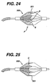
appended Figs. 24 through 27. As seen in Figs. 24 and 25, a slight
modification of the profile p of the filter membrane 500 will result in easier
folding of the membrane inwardly either prior to or subsequent to capture of
embolic material. That is, as seen in Fig. 24, the membrane is provided with a
scallops S forming profile P. As seen in Fig. 25, the profile P contains more
curves C, shaped somewhat like a bat's wings. In either event however, this
reduced leading edge profile for the filter membrane 500 allows for easier
folding of the membrane subsequent to its collection of embolic material. The
membrane 500 folds more readily because at its distal ends 501 folds, there is
less material to be placed in close juxtaposition. Accordingly, this type of fold
will enable the material to be captured, and yet also provide for more ready
disposition of the membrane.
-
The membrane 500 can be cut in such a profile by standard techniques,
including among other things, laser cutting, as is discussed above.
-
As seen in the embodiment of Fig. 26, a balloon 601 is incorporated
outside the basket element 600 of the filter membrane 550 so that element 600
"floats" inside the balloon 600. In this embodiment, the balloon 601 is placed
outside of the filter mechanism 550. The balloon 601 is then laser drilled,
creating larger holes for entrance of embolic articles. A basket is thus formed
"inside" the balloon. The balloon is then seated as a basket only at its distal
end. In this fashion, the filter element is incorporated into the profile of a
balloon and so is further able to provide for embolic capture.
-
As seen in Fig. 27, struts 700 are placed intermediate the struts 702
used to fold the membrane 701 inward during collapse. These struts provide
for greater stability of the membrane 701 during emplacement in the artery. For
even further stability, there could be placed smaller struts (not shown) bridging
these fingers.
-
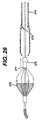
As seen in Figure 28, the proximal marker band 371 of the basket 370
includes a male barb-type snap 372. The capture sheath tip 375 includes the
female portion 373. This mechanism lends itself especially well to rapid
exchange catheter designs, eliminating the need for a locking mechanism at the
hub end of the capture sheath. Barb 372 is generally formed of metal, such as
stainless steel. Snap ring 373 is a generally polymeric material, and mates with
barb 372 to lock the basket 370 into place upon capture.
-
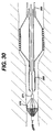
As seen in Figure 30, a capture tip 380 is integrated with a stent delivery
system 385, or with a PTCA catheter (not shown). After stent delivery or PTCA,
the stent delivery system 385 can be advanced to recapture the basket 370.
This avoids an exchange of systems to provide for a dedicated capture sheath.
(The mechanism can also be applied to self-expanding stent delivery systems
with only minor modifications) as seen in Figure 29, outer body 395 releases
stent 393. Inner body 394 contains capture tip 392 which engages marker
band 371, thereby capturing basket 370.
-
Finally, as seen in Figure 31, a separate or stand-alone capture tip 397
can be attached distal of any interventional device. A snap configuration similar
to the previously described mechanism would be incorporated to secure the tip
to the basket. The interventional device would be used to advance the capture
tip 397 over the basket 370.
-
It is to be understood that any of the embodiments described herein can
be made by laser cutting the membrane mechanism possibly even into a self
expanding hypo tube. Further, the mechanism can be made by dipping the
device into a bath containing the polymer of the membrane. In this fashion, the
dimensional depth of the bath can be adjusted to provide for optimal
performance of the membrane material.
-
The wires, membrane, and other materials of this embodiment are
consistent with those described above.
-
As seen in Figures 32a and 32b, the present invention may be given a
slightly different configuration, in order to ensure the consistent capture of
embolic material upon closure of the capture sheath. Here, there is seen a
capture mechanism 450, alike in generally all respects to the devices described
above. Mechanism 450 contains struts 460, which splay in their expanded
condition as seem in Figure 32a. Struts 460, again, are preferably formed from
the superelastic material nitinol. Uniquely, however, the struts 460 have a
shape memory configuration that is helical in nature. So, when the struts 460
are urged back to their shape memory configuration, the struts 460 form a taut
spiral about guidewire 470. In so doing, the struts more securely close filter
membrane 480 around any embolic material captured during the procedure.
-
Alternately, the struts 460 do not need to be formed of a shape memory
alloy. Rather, the struts 460 are placed along the guidewire 470 attached to
marker bands 475 so that they are configured into a spiral shape upon closure.
Then, on opening, the marker bands 475 rotate one with respect to the other,
so that struts 460 are straightened, in order to facilitate capture of thrombus. In
either fashion, the "closed" position of struts 460 is clearly a spiral, so that the
filter 480 closes more tautly about the thrombus captured therein.
-
The preceding specific embodiments are illustrative of the practice of the
invention. It is to be understood, however, that other expedients known to those
skilled in the art or disclosed herein, may be employed without departing from
the spirit of the invention or the scope of the appended claims.