EP1170531A2 - Belt clamp force controller - Google Patents
Belt clamp force controller Download PDFInfo
- Publication number
- EP1170531A2 EP1170531A2 EP01305365A EP01305365A EP1170531A2 EP 1170531 A2 EP1170531 A2 EP 1170531A2 EP 01305365 A EP01305365 A EP 01305365A EP 01305365 A EP01305365 A EP 01305365A EP 1170531 A2 EP1170531 A2 EP 1170531A2
- Authority
- EP
- European Patent Office
- Prior art keywords
- clamp force
- belt
- generator
- regulator
- power
- Prior art date
- Legal status (The legal status is an assumption and is not a legal conclusion. Google has not performed a legal analysis and makes no representation as to the accuracy of the status listed.)
- Withdrawn
Links
Images
Classifications
-
- F—MECHANICAL ENGINEERING; LIGHTING; HEATING; WEAPONS; BLASTING
- F16—ENGINEERING ELEMENTS AND UNITS; GENERAL MEASURES FOR PRODUCING AND MAINTAINING EFFECTIVE FUNCTIONING OF MACHINES OR INSTALLATIONS; THERMAL INSULATION IN GENERAL
- F16H—GEARING
- F16H61/00—Control functions within control units of change-speed- or reversing-gearings for conveying rotary motion ; Control of exclusively fluid gearing, friction gearing, gearings with endless flexible members or other particular types of gearing
- F16H61/66—Control functions within control units of change-speed- or reversing-gearings for conveying rotary motion ; Control of exclusively fluid gearing, friction gearing, gearings with endless flexible members or other particular types of gearing specially adapted for continuously variable gearings
- F16H61/662—Control functions within control units of change-speed- or reversing-gearings for conveying rotary motion ; Control of exclusively fluid gearing, friction gearing, gearings with endless flexible members or other particular types of gearing specially adapted for continuously variable gearings with endless flexible members
- F16H61/66272—Control functions within control units of change-speed- or reversing-gearings for conveying rotary motion ; Control of exclusively fluid gearing, friction gearing, gearings with endless flexible members or other particular types of gearing specially adapted for continuously variable gearings with endless flexible members characterised by means for controlling the torque transmitting capability of the gearing
Landscapes
- Engineering & Computer Science (AREA)
- General Engineering & Computer Science (AREA)
- Mechanical Engineering (AREA)
- Control Of Transmission Device (AREA)
- Control Of Eletrric Generators (AREA)
Abstract
Description
- The present invention relates to a belt clamp force controller and in particular a controller for use within a continuously variable transmission belt drive unit for driving a generator within a aircraft power generation system.
- It has been proposed in GB 2220038 that a continuously variable belt drive transmission may be used to drive a constant speed generator from one of the output spools of a gas turbine engine.
- According to a first aspect of the present invention, there is provided a belt clamp force regulator for controlling the clamp force exerted on a drive belt in a continuously variable transmission input stage for a generator, the regulator comprising a clamp force controller having an input for receiving data representative of the amount of power being produced by the generator and for calculating a target clamp force as a function of the amount of power being produced, said clamp force having a predetermined minimum value.
- It is thus possible to provide a controller which enables the clamp pressure and hence the clamp force acting on the belt to be reduced to a minimum value consistent with ensuring slippage between the belt and the pulleys of the continuously variable transmission system does not arise. Control of the clamp force on the belt has a significant effect on the working life of the transmission. It has been estimated that belt wear and fatigue increases exponentially with increasing clamp force on the belt. Thus it is clearly desirable to reduce the clamp force to a minimum value consistent with transmitting power from the prime mover to the generator. However, slippage between the belt and the pulleys results in scoring of the pulleys, wear on the belt, and rapidly results in degradation or failure of the transmission.
- Preferably the clamp force exerted on the belt has a minimum value. This value may be selected to ensure that sudden load changes, or first load application, will not result in the belt starting to slip. Thus the provision of a minimum value acts as a safety margin against slippage occurring.
- Preferably the clamp force applied to the transmission belt of the generator is substantially proportional to the power being supplied at the output of the generator. The value of proportionality may be selected to provide a further safety margin. The transition from a constant force to a proportional force may occur at a point related to the relevant system requirements. Preferably the clamp force is set such that the generator is rated to provide an output in excess of and proportional to its current (i.e. present) output without slippage being expected to occur. The constant of proportionality may be increased to two, or more so as to allow for the possibility where generators are arranged to operate in a pair, and failure of one generator would result in its load being immediately transferred to the remaining functioning generator.
- Preferably the clamp force increases in a continuous manner within increasing load. The clamp force may become constant at forces equivalent to power demands in excess of the physical capability of the generator to supply these demands, even when operated in an overrated mode even for short durations.
- Preferably the controller exhibits hysteresis or an acceptance window in order to prevent "hunting" of the controller about its target value.
- The controller may implement the transfer function as an analogue controller. Alternatively, the compressive force may be scheduled as a function of load within a digital controller.
- According to a second aspect of the present invention, there is provided a method of controlling the clamp force exerted on a drive belt in a continuously variable transmission input stage for a generator, the method comprising the steps of obtaining data representative of the amount of power being produced by the generator, and calculating a target clamp force as a function of the amount of power being provided by the generator, said force having a minimum value.
- According to a third aspect of the present invention, there is provided a generator for use in an aircraft power generation system having a continuously variable belt driven transmission associated with a generator such that the generator rotates at a constant rate throughout a predetermined operating range of a prime mover, the generator controller comprising means for estimating the amount of power being produced by the generator and for calculating a target clamp force to be exerted on the drive belt as a function of the amount of power being produced by the generator, said force having a minimum value.
- The present invention will further be described, by way of example, with reference to the accompanying drawings, in which:
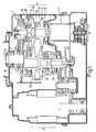
- Figure 1 schematically represents a generator and continuously variable transmission for use within an aircraft power generation system;
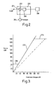
- Figure 2 schematically illustrates the pressure control system for the generator; and
- Figure 3 illustrates a transfer function implemented within the pressure controller.
-
- The generator shown in Figure 1 comprises a housing 1 which encloses a continuously variable transmission generally designated 2 and utilising a drive belt, a low pressure pump 4, a
high pressure pump 6, a generator, generally designated 8, and an oil system disposed throughout the housing 1. - The
belt drive 2 enables the variable speed of aninput shaft 10 which receives a drive from a spool of a gas turbine engine to be converted to a near constant speed such that thegenerator 8 can be run at a near constant speed. In order to do this, afirst shaft 12 of the belt drive mechanism carries aflange 14 which defines aninclined surface 16 against which a drive belt bears. Theshaft 12 also carries a coaxially disposedmovable flange 20 drivingly connected to theshaft 12 via a splined portion (not shown). Themovable flange 20 defines a furtherinclined surface 22 facing towards thesurface 16, which surfaces serve to define a V-shaped channel whose width can be varied by changing the axial position of theflange 20 with respect to the fixedflange 14. Theflange 20 has a circularlysymmetric wall 24 extending towards and co-operating with a generally cupshaped element 26 carried on theshaft 12 to define a firsthydraulic control chamber 28 therebetween which is in fluid flow communication via a control duct (not shown) with an associated control valve. Similarly, a fixedflange 30 and amovable flange 32 are associated with asecond shaft 36 and serve to define a pulley operated by a secondhydraulic control chamber 34. A steel segmented belt having a cross-section in the form of a trapezium, with the outer most surface being wider than the inner most surface is used to interconnect the first and second variable ratio pulleys formed between the pairs of fixed and movable flanges, respectively, in order to drivingly connect the pulleys. - The position of each movable flange with respect to the associated fixed flange is controlled by the hydraulic control actuators. Since the interconnecting belt is of a fixed width, moving the flanges closer together forces the belt to take a path of increased radial distance. The interconnecting belt has a fixed length, and consequently as one movable flange is moved towards its associated fixed flange, the other movable flange must move away from its associated fixed flange in order to ensure that the path from an arbitrary starting point, around one of the pulleys, to the second pulley, around the second pulley and back to the fixed arbitrary starting point remains a constant distance.
- It is important in such a pulley system that the position of the flanges can be well controlled. It is also important that the clamp force exerted upon the belt can be well controlled since belt wear and fatigue increases rapidly with clamp force but belt slippage is damaging to both the belt and the pulleys. Thus a controller or control system (not shown) is provided which controls both the generator frequency and the clamp force, exerted on the belt.
- Figure 2 schematically shows a belt
clamp force controller 200 constituting an embodiment of the present invention. The controller has afirst input 201 for receiving a signal indicative of the amount of power being supplied by the generator, as well as the voltage and power factor. This signal may be derived from monitoring the current being produced by the generator. Current transformers for monitoring generator output current are frequently provided on generators. The generator load signal is applied to a non-inverting input of asummer 202. An output from one ormore pressure transducers 204 is supplied to an inverting input of thesummer 202. The pressure in thehydraulic control chamber - Since the hydraulic pressure as measured by the
pressure sensor 204 can be directly related to the expected load that the generator can supply before belt slippage occurs, then the pressure signal can be compared directly with the load signal provided that a suitable constant of proportionality has been introduced. An output of thesummer 202 representing a difference between the demanded clamp force and actual clamp force is supplied to an input of aload scheduler 206. The load scheduler could be implemented as a classical analogue proportional-integral-derivative controller, but is more likely to be implemented as a digital controller as this allows the transfer function to be tailored to more complex functions than is easily obtained using analogue controllers. An output of thecontroller 206 is then provided to an electrically operatedvalve 208 for regulating the pressure. - Figure 3 shows an example transfer function as implemented within the
controller 206. The abscissa represents the electrical output from the generator expressed in kilowatts. The ordinate represents the clamp force being applied to the belt. However, since the clamp force applied to the belt can be directly related to the load supplied from the generator that would cause the belt to slip, the ordinate has been represented as an equivalent electrical load represented in kilowatts as this is the required drive system power (or KVA at the appropriate power factor) rather than a clamp force acting on the belt as represented in Newtons. This representation allows the function of the controller to be more easily explained. As the load on the drive system is related to the true power, all values of load have been considered to the point of representing their true power value. - The clamp force as implemented in this example comprises a transfer function having distinct first, second and third regions. The first region, as represented by the
line 230, relates to the performance of the clamping device when the generator is under low electrical loading, and typically providing an output in the range of 0 to 30 kW. Under these conditions, the clamp force remains constant at a value equivalent to 45 kW of load. Once the demand on the generator exceeds 30 kW, the transfer function moves into asecond region 232 where the clamp force, as represented by a kW equivalent, is given by: - Thus the clamp force is linearly proportional to the electrical load supplied by the generator and includes a safety margin of 50%. In this example, this second portion of the transfer function is maintained for loads in the range of 30 to 120 kW. For electrical loads in excess of 120 kW, the clamp force is maintained at a constant 180 kW equivalent, as represented by the
third region 234. - In this example, the generator is rated for maximum output at 75 or 90 KVA, 0.75 to 1 power factor. However, it is common for such devices to be able to withstand short term or emergency overrunning, and under such circumstances the generator can supply loads in the region of 150 kW for several seconds.
- It should be noted that other simple transfer functions may also be utilised. Thus the clamp force could, for example, be calculated as being equal to the demand load plus a constant offset, for example 45 kW.
- As a further alternative the safety margin by which the clamp force exceeds the actual demanded load may reduce within increasing demanded load since the capability for load increases to be supplied by the generator diminishes as the electrical power supplied by the generator increases.
- It is thus possible to provide a load controller wherein the clamp force acting on the belt is varied as a function of generator load in order to increase belt life whilst eliminating risk of slippage.
Claims (10)
- A belt clamp force regulator for controlling a clamp force exerted on a drive belt in a continuously variable transmission (2) input stage for a generator (8), the belt clamp force regulator comprising a clamp force controller (200) having an input (201) for receiving data representative of the amount of power being produced by the generator and for calculating a target clamp force as a function of the amount of power being produced, said target clamp force having a predetermined minimum value.
- A belt clamp force regulator as claimed in claim 1 wherein, in use, the regulator seeks to minimise the clamp force consistent with ensuring that slippage between the belt and pulleys of the continuously variable transmission (2) does not occur.
- A belt clamp force regulator as claimed in claim 1 or 2, in which the target clamp force is selected such that the clamp force exerted on the belt has a minimum value.
- A belt clamp force regulator as claimed in claim 3, in which the minimum clamp force is selected such that sudden load changes will not cause the belt to slip with respect to the pulleys.
- A belt clamp force regulator as claimed in any one of the preceding claims, in which the clamp force applied to the belt is substantially proportional, subject to a minimum force being allowed, to the power being supplied by the generator (8).
- A belt clamp force regulator as claimed in claim 5, in which the transition between a constant clamp force to a variable force occurs at a point relevant to system requirements.
- A belt clamp force regulator as claimed in any one of the preceding claims, in which the clamp force on the belt is set such that the generator (8) is rated to provide an output in excess of and proportional to its present output without slippage being expected to occur.
- A belt clamp force regulator as claimed in any one of the preceding claims, in which the clamp force becomes constant for power outputs in excess of a predetermined value.
- A belt clamp force regulator as claimed in any one of the preceding claims, in which the clamp force exerted on the belt is constant below a first generator output value and increases linearly above the first generator output value.
- A method of controlling the clamp force exerted on a drive belt in a continuously variable transmission (2) input stage for a generator (8), the method comprising the steps of obtaining data representative of the amount of power being produced by the generator, and calculating a target clamp force as a function of the amount of power being provided by the generator, said force having a minimum value.
Applications Claiming Priority (2)
| Application Number | Priority Date | Filing Date | Title |
|---|---|---|---|
| GB0016181 | 2000-06-30 | ||
| GBGB0016181.0A GB0016181D0 (en) | 2000-06-30 | 2000-06-30 | Belt clamp pressure controller |
Publications (2)
| Publication Number | Publication Date |
|---|---|
| EP1170531A2 true EP1170531A2 (en) | 2002-01-09 |
| EP1170531A3 EP1170531A3 (en) | 2003-10-15 |
Family
ID=9894834
Family Applications (1)
| Application Number | Title | Priority Date | Filing Date |
|---|---|---|---|
| EP01305365A Withdrawn EP1170531A3 (en) | 2000-06-30 | 2001-06-20 | Belt clamp force controller |
Country Status (3)
| Country | Link |
|---|---|
| US (1) | US20020013188A1 (en) |
| EP (1) | EP1170531A3 (en) |
| GB (1) | GB0016181D0 (en) |
Families Citing this family (1)
| Publication number | Priority date | Publication date | Assignee | Title |
|---|---|---|---|---|
| US20110250998A1 (en) * | 2008-12-26 | 2011-10-13 | Nsk Ltd. | Pulley Support Structure for Belt-Drive Continuously Variable Transmission and Belt-Drive Continuously Variable Transmission |
Citations (1)
| Publication number | Priority date | Publication date | Assignee | Title |
|---|---|---|---|---|
| GB2220038A (en) | 1988-06-28 | 1989-12-28 | Christopher David Whelan | A constant speed drive for electrical generators |
Family Cites Families (10)
| Publication number | Priority date | Publication date | Assignee | Title |
|---|---|---|---|---|
| JPS5635853A (en) * | 1979-08-28 | 1981-04-08 | Nippon Denso Co Ltd | Power transmission system |
| US4321991A (en) * | 1980-01-28 | 1982-03-30 | Deere & Company | Torque responsive disconnect for a V-belt driven element |
| US4571216A (en) * | 1981-12-30 | 1986-02-18 | The Gates Rubber Company | Variable speed belt driven transmission system and method |
| US4541821A (en) * | 1982-11-27 | 1985-09-17 | Aisin-Warner Limited | V-belt type stepless transmission |
| JP2548224B2 (en) * | 1987-08-28 | 1996-10-30 | アイシン・エィ・ダブリュ株式会社 | Belt type continuously variable transmission |
| US5184981A (en) * | 1991-01-07 | 1993-02-09 | Wittke Ernest C | Cam loaded continuously variable transmission |
| US5182968A (en) * | 1991-10-16 | 1993-02-02 | Borg-Warner Automotive Transmission & Engine Components Corporation | Force ratio control of continuously variable transmissions |
| DE4203362C2 (en) * | 1992-02-06 | 1994-02-17 | Piv Antrieb Reimers Kg Werner | Tapered disk gear, in particular for motor vehicles |
| US6099424A (en) * | 1998-12-30 | 2000-08-08 | Hamilton Sundstrand Corporation | Continuously variable transmission with control arrangement and method for recovering from transmission belt slipping |
| US6290620B1 (en) * | 1999-06-25 | 2001-09-18 | Hamilton Sundstrand Corporation | Continuously variable transmission with control arrangement and method for reducing impact of shock load |
-
2000
- 2000-06-30 GB GBGB0016181.0A patent/GB0016181D0/en not_active Ceased
-
2001
- 2001-06-20 EP EP01305365A patent/EP1170531A3/en not_active Withdrawn
- 2001-06-29 US US09/893,675 patent/US20020013188A1/en not_active Abandoned
Patent Citations (1)
| Publication number | Priority date | Publication date | Assignee | Title |
|---|---|---|---|---|
| GB2220038A (en) | 1988-06-28 | 1989-12-28 | Christopher David Whelan | A constant speed drive for electrical generators |
Also Published As
| Publication number | Publication date |
|---|---|
| GB0016181D0 (en) | 2000-08-23 |
| EP1170531A3 (en) | 2003-10-15 |
| US20020013188A1 (en) | 2002-01-31 |
Similar Documents
| Publication | Publication Date | Title |
|---|---|---|
| EP1170530B1 (en) | Controller for a continuously variable transmission | |
| US6290620B1 (en) | Continuously variable transmission with control arrangement and method for reducing impact of shock load | |
| CN102537328B (en) | Utilize the system and method for Hydraulic fluid lubricates variator components | |
| US8892318B2 (en) | Controller and control method of belt type continuously variable transmission | |
| KR20040056375A (en) | Closed loop control of shifting clutch actuators in an automatic speed change transmission | |
| US6099424A (en) | Continuously variable transmission with control arrangement and method for recovering from transmission belt slipping | |
| US20180138836A1 (en) | Variable speed drive system and method for starting and/or operating a variable speed drive system | |
| US20120115678A1 (en) | Controller and control method of belt type continuously variable transmission | |
| GB2484230A (en) | Method and system for controlling aircraft engine starter/generator | |
| US6224509B1 (en) | Method for monitoring of a continuously variable transmission | |
| GB2220038A (en) | A constant speed drive for electrical generators | |
| KR100257852B1 (en) | Engine rotation number controlling method for hydraulic construction machine | |
| US9562546B2 (en) | Hydraulic control circuit and its control method | |
| EP1170531A2 (en) | Belt clamp force controller | |
| JP2011163393A (en) | Hydraulic control device, and control device of belt type continuously variable transmission | |
| US4738104A (en) | Hydraulic power system | |
| US20040058760A1 (en) | Belt-type continuously variable transmission | |
| CN212509412U (en) | Transmission device | |
| JPS5888480A (en) | Input control for hydraulic pump driven by prime mover | |
| US11465767B2 (en) | Electric power generation controller for use in aircraft and electric power generating apparatus including same | |
| JPH03213763A (en) | Control device for continuously variable transmission | |
| CN108700192B (en) | Hydraulic system and method for controlling pressure in a hydraulic system | |
| US10815846B2 (en) | Continuously variable transmission and method for controlling continuously variable transmission | |
| CN113969966A (en) | Transmission and control method of transmission | |
| EP2183506B1 (en) | Hydraulic control system for transmission |
Legal Events
| Date | Code | Title | Description |
|---|---|---|---|
| PUAI | Public reference made under article 153(3) epc to a published international application that has entered the european phase |
Free format text: ORIGINAL CODE: 0009012 |
|
| AK | Designated contracting states |
Kind code of ref document: A2 Designated state(s): AT BE CH CY DE DK ES FI FR GB GR IE IT LI LU MC NL PT SE TR |
|
| AX | Request for extension of the european patent |
Free format text: AL;LT;LV;MK;RO;SI |
|
| PUAL | Search report despatched |
Free format text: ORIGINAL CODE: 0009013 |
|
| RAP1 | Party data changed (applicant data changed or rights of an application transferred) |
Owner name: GOODRICH CONTROL SYSTEMS LIMITED |
|
| AK | Designated contracting states |
Kind code of ref document: A3 Designated state(s): AT BE CH CY DE DK ES FI FR GB GR IE IT LI LU MC NL PT SE TR |
|
| AX | Request for extension of the european patent |
Extension state: AL LT LV MK RO SI |
|
| AKX | Designation fees paid | ||
| REG | Reference to a national code |
Ref country code: DE Ref legal event code: 8566 |
|
| STAA | Information on the status of an ep patent application or granted ep patent |
Free format text: STATUS: THE APPLICATION IS DEEMED TO BE WITHDRAWN |
|
| 18D | Application deemed to be withdrawn |
Effective date: 20040416 |