EP1169112B1 - Electrodeionization apparatus and method - Google Patents
Electrodeionization apparatus and method Download PDFInfo
- Publication number
- EP1169112B1 EP1169112B1 EP00905710A EP00905710A EP1169112B1 EP 1169112 B1 EP1169112 B1 EP 1169112B1 EP 00905710 A EP00905710 A EP 00905710A EP 00905710 A EP00905710 A EP 00905710A EP 1169112 B1 EP1169112 B1 EP 1169112B1
- Authority
- EP
- European Patent Office
- Prior art keywords
- exchange resin
- ion
- electrodeionization apparatus
- resin material
- layer
- Prior art date
- Legal status (The legal status is an assumption and is not a legal conclusion. Google has not performed a legal analysis and makes no representation as to the accuracy of the status listed.)
- Expired - Lifetime
Links
Images


Classifications
-
- C—CHEMISTRY; METALLURGY
- C02—TREATMENT OF WATER, WASTE WATER, SEWAGE, OR SLUDGE
- C02F—TREATMENT OF WATER, WASTE WATER, SEWAGE, OR SLUDGE
- C02F1/00—Treatment of water, waste water, or sewage
- C02F1/46—Treatment of water, waste water, or sewage by electrochemical methods
- C02F1/469—Treatment of water, waste water, or sewage by electrochemical methods by electrochemical separation, e.g. by electro-osmosis, electrodialysis, electrophoresis
- C02F1/4693—Treatment of water, waste water, or sewage by electrochemical methods by electrochemical separation, e.g. by electro-osmosis, electrodialysis, electrophoresis electrodialysis
- C02F1/4695—Treatment of water, waste water, or sewage by electrochemical methods by electrochemical separation, e.g. by electro-osmosis, electrodialysis, electrophoresis electrodialysis electrodeionisation
-
- B—PERFORMING OPERATIONS; TRANSPORTING
- B01—PHYSICAL OR CHEMICAL PROCESSES OR APPARATUS IN GENERAL
- B01D—SEPARATION
- B01D61/00—Processes of separation using semi-permeable membranes, e.g. dialysis, osmosis or ultrafiltration; Apparatus, accessories or auxiliary operations specially adapted therefor
- B01D61/42—Electrodialysis; Electro-osmosis ; Electro-ultrafiltration; Membrane capacitive deionization
- B01D61/44—Ion-selective electrodialysis
- B01D61/46—Apparatus therefor
- B01D61/48—Apparatus therefor having one or more compartments filled with ion-exchange material, e.g. electrodeionisation
-
- B—PERFORMING OPERATIONS; TRANSPORTING
- B01—PHYSICAL OR CHEMICAL PROCESSES OR APPARATUS IN GENERAL
- B01J—CHEMICAL OR PHYSICAL PROCESSES, e.g. CATALYSIS OR COLLOID CHEMISTRY; THEIR RELEVANT APPARATUS
- B01J47/00—Ion-exchange processes in general; Apparatus therefor
- B01J47/02—Column or bed processes
- B01J47/04—Mixed-bed processes
-
- B—PERFORMING OPERATIONS; TRANSPORTING
- B01—PHYSICAL OR CHEMICAL PROCESSES OR APPARATUS IN GENERAL
- B01J—CHEMICAL OR PHYSICAL PROCESSES, e.g. CATALYSIS OR COLLOID CHEMISTRY; THEIR RELEVANT APPARATUS
- B01J47/00—Ion-exchange processes in general; Apparatus therefor
- B01J47/02—Column or bed processes
- B01J47/06—Column or bed processes during which the ion-exchange material is subjected to a physical treatment, e.g. heat, electric current, irradiation or vibration
- B01J47/08—Column or bed processes during which the ion-exchange material is subjected to a physical treatment, e.g. heat, electric current, irradiation or vibration subjected to a direct electric current
-
- C—CHEMISTRY; METALLURGY
- C02—TREATMENT OF WATER, WASTE WATER, SEWAGE, OR SLUDGE
- C02F—TREATMENT OF WATER, WASTE WATER, SEWAGE, OR SLUDGE
- C02F1/00—Treatment of water, waste water, or sewage
- C02F1/42—Treatment of water, waste water, or sewage by ion-exchange
-
- C—CHEMISTRY; METALLURGY
- C02—TREATMENT OF WATER, WASTE WATER, SEWAGE, OR SLUDGE
- C02F—TREATMENT OF WATER, WASTE WATER, SEWAGE, OR SLUDGE
- C02F1/00—Treatment of water, waste water, or sewage
- C02F1/46—Treatment of water, waste water, or sewage by electrochemical methods
- C02F1/469—Treatment of water, waste water, or sewage by electrochemical methods by electrochemical separation, e.g. by electro-osmosis, electrodialysis, electrophoresis
- C02F1/4693—Treatment of water, waste water, or sewage by electrochemical methods by electrochemical separation, e.g. by electro-osmosis, electrodialysis, electrophoresis electrodialysis
Definitions
- the present invention relates to an electrodeionization apparatus and method and, more particularly, to an electrodeionization apparatus and method including electroactive media combinations that provide more uniform electric current distribution, degree of resin regeneration, and deionization performance.
- Electrodeionization is a process that removes ionizable species from liquids using electrically active media and an electrical potential to influence ion transport.
- the electrically active media may function to alternately collect and discharge ionizable species, or to facilitate the transport of ions continuously by ionic or electronic substitution mechanisms.
- EDI devices may comprise media of permanent or temporary charge, and may be operated batchwise, intermittently, or continuously.
- EDI devices may be operated to cause electrochemical reactions specifically designed to achieve or enhance performance, and may comprise electrically active membranes such as semipermeable ion exchange or bipolar membranes.
- CEDI continuous electrodeionization
- EDR electrodiaresis
- a typical CEDI device comprises alternating electroactive semipermeable, anion and cation ion-exchange membranes.
- the spaces between the membranes are configured to create liquid flow compartments with inlets and outlets.
- a transverse DC electrical field is imposed by an external power source using electrodes at the bounds of the membranes and compartments. Often, electrolyte compartments are provided so that reaction products from the electrodes can be separated from the other flow compartments.
- ions in the liquid are attracted to their respective counterelectrodes.
- the compartments bounded by the electroactive anion membrane facing the anode and the electroactive cation membrane facing the cathode become ionically depleted, and the compartments bounded by the electroactive cation membrane facing the cathode and the electroactive anion membrane facing the anode become ionically concentrated.
- the volume within the ion-depleting compartments, and preferentially within the ion-concentrating compartments is also comprised of electrically active media.
- the media may comprise intimately mixed anion and cation exchange resins.
- the ion-exchange media enhances the transport of ions within the compartments and can also participate as a substrate for controlled electrochemical reactions.
- the configuration is similar in EDR devices, except that the media comprise separate, and sometimes altemating, layers of ion-exchange resin.
- each layer is substantially comprised of resins of the same polarity (either anion or cation resin) and the liquid to be deionized flows sequentially through the layers.
- Electroactive media of permanent charge may change their electrical resistance properties in undesired ways depending on their ionic form. For example, in the ion substitution of sodium with hydrogen ion in EDR, most cation exchange resins will preferentially transport hydrogen ion over the desired transport of sodium ion. This results in electrical inefficiencies and, under certain circumstances, may cause pH shifts that are detrimental to valuable products within the liquid.
- a given electroactive media may be desirable for transport properties, such as the Type II anion membrane and resins for continuous deionization and EDR, but may have the undesirable properties of catalyzing the ionization reaction of water to hydrogen and hydroxide ions.
- NL 776,469 discloses an electrolytic deionization apparatus that includes separate strata of anion exchanger and cation exchanger.
- WO97/46492 discloses an electrodeionization apparatus for improving the rate of silica removal in which nontreated water first passes through an anion-exchange layer followed by other ion-exchange materials.
- EP-A-0870533 discloses an electrodeionization apparatus having a demineralising compartment having mixed layers of cation and anion exchange resin beads. However, there is no indication of balancing the conductivity of the layers, or analysis of the flow caused by such mixing
- an electrodeionization apparatus comprising:
- the cation resin material could be doped with the specialized electroactive media.
- the specialized electroactive media includes about 60 percent of a Type I anion resin material.
- the invention is directed to a method of purifying a fluid in an electrodeionization apparatus, comprising:
- the present invention is directed to an electrodeionization apparatus and method that provide relatively high purity water and low electrical resistance by balancing the relative conductivity of alternating layers of ion exchange resin material positioned in an ion-depleting compartment.
- the electrodeionization apparatus provides more uniform electric current distribution and deionization performance.
- An electrodeionization apparatus may be based on technologies such as continuous electrodeionization, electrodiaresis, filled-cell electrodialysis, electrochemical ion exchange, capacitive deionization, and the like.
- the electrodeionization apparatus is an EDI apparatus, such as those disclosed by Kunz, in U.S. Patent Nos. 4,636,296 and 4,687,561.
- the electrodeionization apparatus may be based on various configurations, such as a spiral design, a plate and frame design, and a circular design.
- the method of the invention involves layering various types of electroactive media, each having a different conductivity value, in an ion-depleting compartment.
- the conductivity of the alternating layers of ion exchange resin material are balanced in order to provide more uniform current distribution and, ultimately, improved deionization performance.
- the terms "balanced” or “balancing,” mean a reduction in the difference in conductivity between two adjacent layers of electroactive media.
- One potential problem that may arise when the current distribution is unbalanced arises in instances where ion exchange resin materials are regenerated in situ by hydrogen and hydroxyl ions, as disclosed in U.S. Patent No. 5,858,191. As disclosed, resin regeneration takes place where the majority of current flows, and little or no regeneration takes place elsewhere.
- the current distribution of the apparatus is balanced by doping at least one layer of the electroactive media.
- Doped material means an electroactive media to which a dopant material has been added, for the purpose of adjusting the electrochemical characteristics of the electroactive media.
- the "dopant material” may be an inert or an electroactive media, preferably anion or cation exchange resin beads.
- the mechanism of ion exchange is based on ionic transport. That is, ions of opposing charges are simultaneously transported from the deionization chamber in opposing directions. Such a mechanism does not take place in intimate mixtures of ion exchange materials having the same charge, or mixtures of a single charge and an inert material. That is, they will never act as a mixed bed.
- ionic substitution predominates, the majority of current flows in one direction, and the ions of interest are transported in a single direction.
- an electroactive material may be considered “doped" up to the point at which the transport of ions in both directions is the predominant mechanism, i.e. until the electroactive material begins to function as a mixed bed.
- mixed beds in which ionic transport ceases or is minimized and in which ionic substitution predominates may be considered doped materials for purposes of the present invention.
- the maximum amount of dopant that may be added to an electroactive media before ionic transport predominates will vary according to the materials used.
- alternating layers of anion exchange resin beads and cation exchange resin beads may be positioned in the ion-depleting compartment, in any sequence.
- electroactive media are used throughout the application, and are described in more detail below. That is, either anion exchange resin beads or cation exchange resin beads may be positioned in the first, or topmost, layer of the ion-depleting compartment. Moreover, either, or both layers of the beads may be doped. For ease of manufacturing, it is preferred that the layers are doped using beads from the alternating layers.
- a layer of anion exchange resin beads is preferably doped with cation exchange resin beads of a type used in an adjacent layer.
- a layer of cation exchange resin beads is preferably doped with anion exchange resin beads of a type used in an adjacent layer.
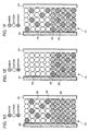
- FIGS. 1A-1F varying schematic, cross-sectional views of an ion-depleting compartment 10 according to the present invention are shown.
- alternating layers, or beds, of ion exchange resin material are positioned in the ion-depleting compartment 10 in a central space formed between an anion-permeable membrane 26 and a cation-permeable membrane 24.
- the central space, or inter-membrane spacing may be varied depending on the desired purity of the product water.
- the inter-membrane spacing may be adjusted depending on the desired product water purity, and is typically greater than about 1.6 mm (1/16 inch).
- the preferred inter-membrane spacing is in the range of about 1.6 mm (1/16 inch) to about 4.8 mm (3/16 inch), and most preferably about 3.2 mm (1/8 inch).
- the preferred inter-membrane spacing is in the range of about 6.4 mm (1/4 inch) to about 12.7 mm (1/2 inch), most preferably about 9.6 mm (3/8 inch).
- At least one layer of ion exchange resin material 28 and ion exchange resin material 30 is required in the ion-depleting compartment of the present invention, although more may be used.
- the number of layers in the ion-depleting compartment may be determined, in part, by the height of the module frame.
- the thickness of the layers may vary depending, in part, on the inter-membrane spacing. In practice, the layer thickness, which is also known as the bed height, is limited by the minimum thickness required to reduce shifting and undesired mixing of the alternating layers of resins during use. In some instances, it may be necessary to vary the thickness of the alternating layers, however, it is preferred that the individual layers in the ion-depleting compartment have substantially the same thickness. Although as few as two alternating resin layers may be used in the ion-depleting compartment, up to eight or more resin layers of equal or different heights are typically used.
- the first, or topmost layer is preferably an anion exchange resin material 28, and the second layer is preferably a cation exchange resin material 30.
- the first layer of anion exchange resin material 28 is preferably doped with a dopant material 38, while the second layer of cation exchange resin beads 30 is preferably undoped.
- the first layer of anion exchange resin material 28 is preferably undoped, while the second layer of cation exchange resin material 30 is preferably doped with a dopant material 38.
- both the first anion exchange resin material layer 28 and the second cation exchange resin material layer 30 are preferably doped with dopant material 38.
- FIGS. 1D-1F illustrate another aspect of the invention, in which the first, or topmost layer in the ion-depleting compartment is a cation exchange resin material 30, and the second layer is an anion exchange resin material 28.
- the first cation exchange resin material layer 30 is preferably doped with a dopant material 38, while the second anion resin material layer 28 is preferably undoped.
- the first cation exchange resin material layer 30 is preferably undoped, while the second anion exchange resin material 28 is preferably doped with a dopant material 38.
- FIG. 1D the first cation exchange resin material layer 30 is preferably doped with a dopant material 38, while the second anion exchange resin material 28 is preferably doped with a dopant material 38.
- both the first cation exchange resin material layer 30 and the second anion exchange resin material layer 28 are preferably doped with dopant material 38.
- the alternating layers When either, or both, of the alternating layers are doped, they may be doped with the same dopant material, or they may be doped with different dopant materials.
- the dopant material may be an inert or an electroactive media, preferably anion or cation exchange resin beads.
- the optimum ratios of dopant material to ion exchange resin beads may vary based, in part, on the inter-membrane spacing, the thickness of the layers, the composition of both the dopant material and the ion exchange resin beads to be doped, the size and uniformity of the beads, and the functional groups in the surface regions of the beads. It will be readily apparent to those of skill in the art that as the difference in conductivity between two resins increases, the amount of resin required to effect a change in the conductivity of the ion exchange resin material may increase. In some instances, it may be desirable to minimize the amount of dopant material in order to prevent or minimize changes in the properties of the ion exchange resin material to which it is added.
- the remaining ion-concentrating and electrode compartments may be filled with conventional ion exchange resin material, which may be alternated as in the ion-depleting compartment. These compartments may also be filled with an inert material, such as, but not limited to, polypropylene. Alternatively, the remaining ion-concentrating and electrode compartments may include an inert structure, such as a screen or netting positioned therein.
- any type of electroactive media may be used in the ion-concentrating and electrode compartments, including, but not limited to cation exchange resin material, Type I anion exchange resin material, Type Il anion exchange resin material, weak base anion exchange resin material, synthetic materials, including carbon, zeolite resin material, inert materials, and mixtures thereof, which are described in more detail below.
- An inert material may be formed from any material which does not conduct current or take part in water dissociation, while permitting fluid flow to pass through the ion-depleting cell. However, deionization performance will vary depending on the choice of resin material used in such compartments.
- any of the embodiments disclosed herein it is advantageous to use the smallest possible bead diameter in order to maximize the available surface area of the electroactive media.
- smaller beads result in increased pressure drops across the ion-depleting chamber, which decreases operating efficiency. Therefore, the minimum size of the beads is limited by the maximum acceptable pressure drop across the ion-depleting compartment, which may vary depending on the apparatus design.
- One of ordinary skill in the art would be able to select the size of the beads through routine experimentation, using the deionization performance as the determining factor.
- deionization performance may be improved further by using substantially uniformly sized ion exchange resin beads in the alternating layers positioned in the ion-depleting compartment.
- substantially uniform as used herein with reference to the bead size, means that 90 percent of the beads are within +/- 10 percent of the mean bead size, and that the relative average size of one ionic form of beads to a second ionic form of beads in a mixture of beads is at least 0.8.
- the packing density and size of voids between the beads will vary depending on the volume to be filled, as well as the size and uniformity of the beads.
- the beads When non-uniform beads are used, the beads are typically packed more tightly in some areas, resulting in a variety of void sizes or volumes, with the void volumes varying within the chamber. Consequently, current may travel through the more tightly packed areas, resulting in non-uniform current distribution.
- the beads when uniform beads are used, the beads are packed more uniformly throughout the chamber volume, resulting in more uniformly sized voids throughout the chamber volume, and ultimately providing more uniform current distribution. It should be understood that as the ratio of substantially uniform beads to non-uniform beads increases, greater increases in deionization performance are achieved. That is, it is not necessary to use 100 percent substantially uniform beads in order to achieve benefits in deionization performance.
- electroactive media in the form of ion exchange resin materials include, but are not limited to, DOWEXTM MARATHONTM series resins, (e.g., DOWEXTM MARATHONTM C cation resins, MARATHONTM A and MARATHONTM A2 anion resins), DOWEXTM WBA (weak base) anion resins, DOWEXTM 11 Type I anion resin, DOWEXTM SAR anion resin (e.g., DOWEXTM SAR Type II anion resins).
- DOWEXTM MARATHONTM series resins e.g., DOWEXTM MARATHONTM C cation resins, MARATHONTM A and MARATHONTM A2 anion resins
- DOWEXTM WBA weak base anion resins
- DOWEXTM 11 Type I anion resin DOWEXTM SAR anion resin (e.g., DOWEXTM SAR Type II anion resins).
- ion exchange resins include the AMBERJETTM series resins (trademark of Rohm & Haas Corporation, Philadelphia, PA), such as, for example, AMBERJETTM 4600 Type II anion resins.
- DOWEXTM MARATHONTM C cation resin is a gel-type strong acid cation exchange resin with sulfonic acid functional groups.
- DOWEXTM MARATHONTM A is a gel-type strong base Type I anion exchange resin with quaternary ammonium functional groups.
- DOWEXTM MARATHONTM A2 is a gel-type strong base Type II anion exchange resin with dimethyl ethanolamine functional groups.
- DOWEXTM MARATHONTM MSA and MSC series resins are particularly preferred examples of ion exchange resin material.
- DOWEXTM MARATHONTM MSA is a high capacity, macro porous type I strong base anion exchange resin having functional groups and mean particle sizes ranging from 590 to 690 microns.
- the DOWEXTM MARATHONTM MSC ion exchange resin is a high capacity macro porous strong acid count ion exchange resin having sulfonic acid functional groups and uniform particle sizes ranging from 450 to 570 microns.
- Both the DOWEXTM MARATHONTM MSA and MSC ion exchange resin are characterized by high water content, high degree of cross-linking, therefore are advantageous for removing silica, and are also advantageous for CEDI applications.
- ion exchange resin materials having substantially uniform beads include DOWEXTM MONOSPHERETM 650C cation resin (Dow Chemical Company), having an average bead size of about 650 microns, and DOWEXTM MONOSPHERETM 550A Type I anion resin (Dow Chemical Company), having an average bead size of about 550 microns.
- electroactive media include, but are not limited to, zeolite resin material, synthetic activated carbons, hypercrosslinked sorbent resins such as PUROLITETM HYPERSOL-MACRONETTM sorbent resins (trademarks of Purolite Company, Bala Cynwyd, PA), synthetic carbonaceous adsorbents, such as AMBERSORBTM carbonaceous adsorbents (trademark of Rohm & Haas Corporation) and G-BACTM adsorbents (trademark of Kureha Chemical Industry Co., Ltd., Japan), polymeric adsorbent resin beads that are prepared by alkyline bridging haloalkylated, porogen-modified, cross-linked copolymer beads, having microporosities in the range of about 0.2 and 0.5 cm 3 /cm, mesoporosities of at least about 0.5 cm 3 /g, and total porosity of at least about 1.5 cm 3 /g as disclosed, for example, by Stringfield, in
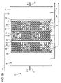
- FIG. 2 a schematic, cross-sectional view of a preferred ion-depleting compartment 10 according to the present invention is shown.
- alternating layers, or beds, of ion exchange resin material 28 and 30 are positioned within the ion-depleting compartment 10 in a central space formed between an anion-permeable membrane 26 and a cation-permeable membrane 24.
- four alternating ion exchange resin layers are positioned in the ion-depleting compartment.
- the inter-membrane spacing is preferably in the range of about 6.4 mm (1/4 inch) to about 9.6 mm (3/8 inch), and the layer thickness is between about 5.08 cm (2 inches) to about 10.16 cm (4 inches).
- the ion-depleting compartment 10 preferably includes a layer of anion exchange resin beads 28, which are alternated with a layer of cation exchange resin beads 30, within the central space formed between the anion-permeable membrane 26 and the cation-permeable membrane 24 of ion-depleting compartment 10.
- the size of the anion and cation resin beads used in the present embodiment ranges from between about 200 ⁇ m and about 800 ⁇ m; more preferably, between about 400 and about 700 ⁇ m; and more preferably between about 550 ⁇ m and about 650 ⁇ m.
- the anion exchange resin beads are a specialized electroactive media, such as described in U.S. Patent No. 5,868,915.
- the cation exchange resin beads are doped with the same anion exchange resin material as used in the alternating layers.
- One such preferred specialized electroactive medium is an anion exchange resin material that includes between about I percent and about 20 percent; more preferably, between about 5 percent and about 15 percent; and, most preferably, about 10 percent, by volume, of Type II or weak base anion exchange resin material, with the remainder comprising Type I anion exchange resin material.
- the anion exchange resin material layers include about 90 percent Type I anion exchange resin material and about 10 percent Type II anion exchange resin material, and the cation exchange resin layers are doped with about 22.5 percent of the Type I anion exchange resin material and 2.5 percent Type II anion exchange resin material, by volume of the layer.
- the cation exchange resin material layers preferably include about 36 percent Type I anion exchange resin material and about 4 percent Type II anion exchange resin material, by volume of the layer.
- the layer of doped cation exchange resin material 30 in the ion-depleting compartment 10 preferably includes between about 50 percent and about 99 percent, by volume, of cation exchange resin material, which is doped with between about 1 percent and about 50 percent, by volume, of anion exchange resin material; more preferably, between about 60 percent and about 90 percent, by volume, of a cation exchange resin material, which is doped with between 10 percent and about 40 percent, by volume, of anion exchange resin material; and more preferably, between about 70 percent and about 80 percent, by volume, of a cation exchange resin material, which is doped with between about 20 percent and about 30 percent of anion exchange resin material, by volume, based on the volume of the layer.
- the doped cation exchange resin layers 30, according to this aspect of the invention preferably include between about 50 percent and about 99 percent cation exchange resin material, which are doped with between about 0.1 percent and about 5 percent of Type II anion exchange resin material, and between about 0.9 percent and about 45 percent Type I anion exchange resin material; more preferably, between about 60 percent and about 90 percent cation exchange resin material, which is doped with between about 1 percent and about 4 percent of Type II anion exchange resin material, and between about 9 percent and about 36 percent Type I anion exchange resin material; more preferably, about 70 percent to about 80 percent cation exchange resin material, which is doped with between about 2 percent and about 3 percent of Type II anion exchange resin material, and between about 18 percent and about 27 percent Type I anion exchange resin material, by volume, based on the volume of the laye.
- Type II or weak base anion exchange resin material in the specialized electroactive media increases, the ability of the media to dissociate in solutions along the entire pH range and to split and exchange neutral salts decreases due to the decrease in volume of Type I anion exchange resin material in the layer. Therefore, when using the previously described specialized electroactive media, as in the present embodiment, balancing the conductivity of the alternating layers of cation exchange resin materials and anion exchange resin materials, by decreasing the conductivity of the layers of cation exchange resin beads, so as not to affect the properties of the anion exchange resin beads used in the layers, has been found to be more preferable than doping the layers of anion exchange resin beads.
- FIG. 3A illustrates schematic, cross-sectional views of the fluid and ion flow paths through one preferred EDI apparatus of the invention.
- the EDI module 12 includes ion-depleting compartments 10 and an ion-concentrating compartment 14 positioned between the ion-depleting compartments.
- the ion-depleting compartments 10 are bordered by an anolyte compartment 16 and a catholyte compartment 18.
- end blocks are positioned adjacent to end plates (not shown) to house an anode 20 and a cathode 22 in their respective compartments.
- Cation-selective membranes 24 and anion-selective membranes 26 are typically sealed to the periphery of both sides of the compartments.
- Alternating layers, or beds, of ion exchange resin material 28 and 30 are positioned within the ion-depleting compartment 10 in a central space formed between the cation-permeable membrane 24 and the anion-permeable membrane 26.
- the ion-depleting compartment 10 is illustrated, as in FIG. 2, with four alternating ion exchange resin layers positioned therein, and with an inter-membrane spacing in the range of about 6.4 mm (1/4 inch) to about 12.8 mm (1/2), more preferably about 9.6 mm (3/8 inch), and a layer thickness or bed height of between about 5.08 cm (2 inches) to about 10.16 cm (4 inches).
- the ion-concentrating and electrode compartments may be empty or may be filled with other types of electroactive media.
- the electrode compartments and the ion-concentrating compartments of the EDI apparatus illustrated in FIG. 3A do not contain any electroactive media positioned therein. However, if desired, one or both of the electrode and ion-concentrating compartments may contain any of the electroactive media described herein.
- FIG. 3B which is a schematic, cross-sectional view through the electrodeionization apparatus of FIG. 3A
- the ion-concentrating compartment is filled with alternating layers of ion exchange resin beads, as in the ion-depleting compartment.
- the first and third layers of the ion-concentrating compartment are doped cation resin material, and the second and fourth layers are the specialized electroactive media described previously.
- FIG. 3C is a schematic, cross-sectional view of a preferred electrodeionization apparatus, as illustrated in FIG. 3A, in which the ion-concentrating compartment is filled with uniformly sized cation exchange resin beads.
- the ion-concentrating compartment is filled with a strong acid cation exchange resin material, preferably including sulfonic acid functional groups.
- a strong acid cation exchange resin material is DOWEXTM MONOSPHERETM 650C (not shown), which includes uniformly sized resin beads.
- a liquid to be purified 32 which may be a reverse osmosis product stream, typically having dissolved cationic and anionic components, is fed through the ion-depleting compartments 10, wherein the anionic components are attracted to the anion exchange resin 28 and the cationic components are attracted to the cation exchange resin beads 30.
- An electric field is then applied across the anode 20 and cathode 22 at the opposite ends of the module. The electric current passes perpendicularly to the fluid flow such that the dissolved cationic and anionic components migrate from the alternating ion exchange resin layers in the direction of their corresponding electrode. Cationic components migrate through the cation-selective membrane 24 into the adjacent ion-concentrating compartment 14.
- anion-selective membrane on the opposite side of the ion-concentrating compartment prevents further migration, thereby trapping the cationic components in the ion-concentrating compartment.
- the process for the anionic components is similar but occurs in the opposite direction; anionic components migrate through the anion-selective membrane 26 into the ion-concentrating compartment 14 and a cation-selective membrane 24 on the other side of the ion-concentrating compartment prevents further migration to trap the anionic components in the ion-concentrating compartment.
- Ionic components are depleted from the ion-depleting compartments 10 and increased in the ion-concentrating compartments 14, forming a high purity product stream 34 and a concentrate stream 36.
- the electrodeionization apparatus may be operated under conditions of chemical solute, or temperature cycling, and/or electrical field polarity cycling or reversal, as described in co-pending application 08/717,781.
- each compartment was bounded by a resin sheet membrane, with an inter-membrane spacing of about 9.6 mm (3/8 inch).
- Alternating layers of ion exchange resin material were positioned in the ion-depleting compartments of the electrodeionization apparatus.
- Each ion-depleting compartment contained four alternating layers, beginning with a layer of anion exchange resin beads.
- the bed height, or layer thickness ranged from about 5.08 cm (2 inches) to about 10.16 cm (4 inches).
- a reverse osmosis permeate stream having a conductivity of about 3.0 to about 5.0 ⁇ S/cm at a temperature of between about 18°C and about 20°C, was used as the feed in each example.
- the modules were operated at a flow rate of about 1.6 lpm/cell-pair, with a product recovery of about 85 percent.
- the applied DC amperage to the module was 1.5 A, which corresponded to a current density of about 3 mA/cm 2 .
- Each ion-depleting compartment contained four alternating layers, beginning with a layer of substantially uniform anion exchange resin beads.
- the anion exchange resin beads used in the alternating layers of each ion-depleting compartment contained 90 percent of substantially uniform Type I anion exchange resin beads (DOWEXTM MONOSPHERETM 550A) and 10 percent of uniform Type II anion exchange resin beads (AMBERJET 4600).
- the layer of cation exchange resin beads used in the alternating layers of Module A were undoped strong acid cation exchange resin beads (DOWEXTM MONOSPHERETM 650C), also having a substantially uniform bead size.
- the cation layers were doped in order to balance the conductivity of the alternating layers.
- the layers of cation exchange resin beads used in the alternating layers of Module B were doped using about 40 percent of the anion exchange resin beads used in the layers of both Module A and Module B.
- DOEXTM MONOSPHERETM 650C uniform strong acid cation resin
- DOWEXTM MONOSPHERETM 550A 36 percent of the uniform Type I anion exchange resin beads
- AMBERJET 4600 4 percent of a Type II anion exchange resin beads
- Module A Layers Type I Anion Exchange Resin Beads Type II Anion Exchange Resin Beads Cation Exchange Resin Beads First 90 % uniform 10 % uniform 0 % Second 0 % 0 % 100 % uniform Third 90 % uniform 10 % uniform 0 % Fourth 0 % 0 % 100 % uniform Module B Layers Type I Anion Exchange Resin Beads Type II Anion Exchange Resin Beads Cation Exchange Resin Beads First 90 % uniform 10 % uniform 0 % Second 36 % uniform 4 % uniform 60 % uniform Third 90 % uniform 10 % uniform 0 % Fourth 36 % uniform 4 % uniform 60 % uniform
- Module A and Module B were evaluated with regard to the product resistivity, product pH, and electrical resistance, recorded after reaching a steady state of operation. As shown below in Table 2, the electrical resistance of Module A was lower than Module B, the pH of the product from Module A was slightly acidic, and the product resistivity of Module A was lower than Module B.
- the cation exchange resin beads were not doped, as in Module A, the conductivity of the alternating layers was less balanced, and more of the current traveled through the relatively highly conductive cation resin layers. In contrast, when the cation exchange resin beads were doped, as in Module B, current was more evenly distributed through the module, resulting in improved deionization performance.
- Module Product Resistivity (M ⁇ -cm) Product pH Electrical Resistance ( ⁇ ) A 0.16 ⁇ 7.0 8.53 B 15.4 ⁇ 7.0 28.3
- the effectiveness of the electrodeionization apparatus of the present invention was evaluated with respect to an electrodeionization apparatus utilizing non-uniform anion exchange resin beads.
- Each ion-depleting compartment contained four alternating layers, beginning with a layer of anion exchange resin beads.
- the anion exchange resin beads used in the alternating layers of each ion-depleting compartment contained 90 percent of non-uniform Type I anion exchange resin beads (DOWEXTM 11, non-uniform grade) and 10 percent of uniform Type II anion exchange resin beads (AMBERJET 4600).
- the cation resin beads used in the alternating layers of Module A were substantially uniform undoped strong acid cation exchange resin beads (DOWEXTM MONOSPHERETM 650C).
- Modules B and C included alternating layers of doped cation exchange resin beads, according to the present invention, in order to balance the conductivity of the alternating layers.
- the doped cation exchange resin beads used in the alternating layers of Module B contained 60 percent of the uniform strong acid cation resin (DOWEXTM MONOSPHERETM 650C) and 40 percent of the same anion exchange resin beads used in the alternating layers of Modules A, B, and C ((i.e.
- Module C contained the same type of resins as Module B, but the doping ratio of the cation resin beads was less. Accordingly, the layers of cation exchange resin beads used in the alternating layers of Module C contained the same uniform strong acid cation resin beads (DOWEXTM MONOSPHERETM 650C), doped with about 25 percent of the same anion exchange resin beads in the alternating layers of the Module ((i.e.
- Module A Layers Type I Anion Exchange Resin Beads Type II Anion Exchange Resin Beads Cation Exchange Resin Beads First 90 % non-uniform 10 % uniform 0 % Second 0 % 0 % 100 % uniform Third 90 % non-uniform 10 % uniform 0 % Fourth 0 % 0 % 100 % uniform Module B Layers Type I Anion Exchange Resin Beads Type II Anion Exchange Resin Beads Cation Exchange Resin Beads First 90 % non-uniform 10 % uniform 0 % Second 36 % non-uniform 4 % uniform 60 % uniform Third 90 % non-uniform 10 % uniform 0 % Fourth 36 % non-uniform 4 % uniform 60 % uniform Module C Layers Type I Anion Exchange Resin Beads Type II Anion Exchange Resin Beads Cation Exchange Resin Beads First 90 % non-uniform 10 % uniform 0
- Modules A, B, and C were evaluated with regard to the product resistivity, product pH, and electrical resistance, recorded after reaching a steady state of operation. As shown below in Table 4, Module A, in which the conductivity of the alternating layers was not balanced, had the lowest product resistivity and electrical resistance, with slightly acidic product water. Module B, which had the same ratios of resins as used in Module B of the previous Example, but used non-uniform resins, had very low product resistivity, the highest electrical resistance, and slightly basic product water. Module C had the best deionization performance, with very high product resistivity, relatively high electrical resistance, and a neutral pH. Module Product Resistivity (M ⁇ -cm) Product pH Electrical Resistance ( ⁇ ) A 0.12 ⁇ 7.0 8.5 B 3.42 > 7.0 16.5 C 16.3 ⁇ 7.0 14.8
- Modules B and C of Experiment II The only difference between Modules B and C of Experiment II is the ratio of dopant material in the layers of cation exchange resin beads. In Module B, the ratio was 40 percent dopant material to 60 percent cation exchange resin beads, and in Module C, the ratio was 25 percent dopant material to 75 percent cation exchange resin beads. As a result of the 15 percent reduction in dopant material contained in the layers of cation exchange resin beads, a 4 to 5 fold increase in product resistivity and slightly lower electrical resistance was produced in Module C.
- the electrodeionization apparatus and method of the present invention can be applied to processes that are presently not practically feasible due to lack of scaling and fouling resistance, temperature resistance, chemical resistance, or electrical efficiency. Typical applications would be the purification and softening of relatively untreated municipal water, relatively untreated well water and brackish water, and water containing foulants such as polyelectrolytes, tannins, lignins, fulvic acid, and other polar or weakly ionized or large ionized organic compounds, foulants such as iron, sulfide, phosphates, silicates, and other multivalent ions.
- foulants such as polyelectrolytes, tannins, lignins, fulvic acid, and other polar or weakly ionized or large ionized organic compounds
- foulants such as iron, sulfide, phosphates, silicates, and other multivalent ions.
Abstract
Description
| Module A Layers | Type I Anion Exchange Resin Beads | Type II Anion Exchange Resin Beads | Cation Exchange Resin Beads |
| First | 90 % uniform | 10 % uniform | 0 % |
| Second | 0 % | 0 % | 100 % uniform |
| Third | 90 % uniform | 10 % uniform | 0 % |
| Fourth | 0 % | 0 % | 100 % uniform |
| Module B Layers | Type I Anion Exchange Resin Beads | Type II Anion Exchange Resin Beads | Cation Exchange Resin Beads |
| First | 90 % uniform | 10 % uniform | 0 |
| Second | |||
| 36 % uniform | 4 % uniform | 60 % uniform | |
| Third | 90 % uniform | 10 % uniform | 0 |
| Fourth | |||
| 36 % uniform | 4 % uniform | 60 % uniform |
| Module | Product Resistivity (MΩ-cm) | Product pH | Electrical Resistance (Ω) |
| A | 0.16 | < 7.0 | 8.53 |
| B | 15.4 | ~7.0 | 28.3 |
| Module A Layers | Type I Anion Exchange Resin Beads | Type II Anion Exchange Resin Beads | Cation Exchange Resin Beads |
| First | 90 % non-uniform | 10 % uniform | 0 % |
| Second | 0 % | 0 % | 100 % uniform |
| Third | 90 % non-uniform | 10 % uniform | 0 % |
| Fourth | 0 % | 0 % | 100 % uniform |
| Module B Layers | Type I Anion Exchange Resin Beads | Type II Anion Exchange Resin Beads | Cation Exchange Resin Beads |
| First | 90 % non-uniform | 10 % uniform | 0 |
| Second | |||
| 36 % non-uniform | 4 % uniform | 60 % uniform | |
| Third | 90 % non-uniform | 10 % uniform | 0 |
| Fourth | |||
| 36 % non-uniform | 4 % uniform | 60 % uniform | |
| Module C Layers | Type I Anion Exchange Resin Beads | Type II Anion Exchange Resin Beads | Cation Exchange Resin Beads |
| First | 90 % non-uniform | 10 % uniform | 0 % |
| Second | 22.5 % non-uniform | 2.5 % uniform | 75 % uniform |
| Third | 90 % non-uniform | 10 % uniform | 0 % |
| Fourth | 22.5 % non-uniform | 2.5 % uniform | 75 % uniform |
| Module | Product Resistivity (MΩ-cm) | Product pH | Electrical Resistance (Ω) |
| A | 0.12 | < 7.0 | 8.5 |
| B | 3.42 | > 7.0 | 16.5 |
| C | 16.3 | ~ 7.0 | 14.8 |
| Module B (Experiment I) | Module B (Experiment II) | Module C (Experiment II) | |
| Percent Dopant material in Cation Exchange Resin layer | 46% | 40% | 25% |
| Bead Characteristics | Uniform | Non-uniform | Non-uniform |
| Product Resistivity (MΩ-cm) | 15.4 | 3.4 | 16.3 |
| Product pH | ~7.0 | > 7.0 | ~7.0 |
| Electrical Resistance (Ω) | 28.3 | 16.5 | 14.8 |
Claims (51)
- An electrodeionization apparatus, comprising:characterized in that the conductivity of the alternating layers is balanced by said dopant, the dopant material is an inert or electroactive media, and the predominant mechanism of ion exchange in the at least one layer is the transport of ions of interest in a single direction.an ion-depleting compartment comprising alternating layers of ion exchange resin material wherein at least one said alternating layers comprises a dopant material,
- The electrodeionization apparatus of Claim 1 wherein the compartment comprises alternating layers of anion exchange resin material and cation exchange material, wherein either or both layers are doped.
- The electrodeionization apparatus of Claim 1 wherein the compartment comprises at least a first layer of anion exchange material and a second layer of cation exchange material, and wherein the at least first layer is doped with a dopant material.
- The electrodeionization apparatus of Claim 1 wherein at least one of said alternating layers comprises a specialized electroactive media, and said specialized electroactive media comprises a Type I anion exchange resin material, and at least one of said alternating layers comprises a cation exchange resin material and a dopant.
- The electrodeionization apparatus of Claim 4, wherein said specialized electroactive media further comprises a material selected from the group consisting of Type II anion exchange resin material, weak base anion exchange resin material, and mixtures thereof.
- The electrodeionization apparatus of Claim 4 or Claim 5 wherein said dopant material comprises specialized electroactive media; and
wherein said specialized electroactive media comprises at least about 60 percent by volume of a Type I anion exchange resin material. - The electrodeionization apparatus of Claim 6, wherein a first layer or a second layer in said ion-depleting compartment comprises said dopant and cation exchange resin material.
- The electrodeionization apparatus of Claim 7, wherein said first layer or second layer comprises about 40 percent of said specialized electroactive media.
- The electrodeionization apparatus of Claim 8, wherein said first layer or second layer comprises about 25 percent of said specialized electroactive media.
- The electrodeionization apparatus of Claim 5, wherein said specialized electroactive media comprises about 90 percent of said Type I anion exchange resin material.
- The electrodeionization apparatus of any preceding Claim, wherein said ion-depleting compartment comprises four alternating layers of said ion exchange resin material.
- The electrodeionization apparatus of Claim 11, wherein a first and third layer of said four alternating layers of ion exchange resin material comprise said specialized electroactive media.
- The electrodeionization apparatus of Claim 11, wherein a second and fourth layer of said four alternating layers of ion exchange material comprises said specialized electroactive media.
- The electrodeionization apparatus of Claim 12, wherein a second and a fourth layer of said alternating layers of ion exchange resin material comprise said dopant and cation exchange resin material.
- The electrodeionization apparatus of Claim 13, wherein a first and a third layer of said alternating layers of ion exchange resin material comprise said dopant and cation exchange resin material.
- The electrodeionization apparatus of Claim 14 or claim 15, wherein said layers of dopant and cation exchange resin material comprise about 40 percent of said specialized electroactive media.
- The electrodeionization apparatus of Claim 14 or Claim 15, wherein said layers of dopant and cation exchange resin material comprise about 25 percent of said specialized electroactive media.
- The electrodeionization apparatus of any of the preceding claims, wherein said ion-depleting compartment includes opposing membranes spaced apart by at least about 1.6mm (1/16inch).
- The electrodeionization apparatus of Claim 18, wherein said ion-depleting compartment includes opposing membranes spaced apart by about 1.6 to about 6.4mm (about 1/16 to about ¼ inch).
- The electrodeionization apparatus of Claim 18, wherein said ion-depleting compartment includes opposing membranes, and said inter-membrane spacing is about 6.4 to about 12.7mm (about ¼ to about ½ inch).
- The electrodeionization apparatus of any one of the preceding Claims, wherein said alternating layers each comprise ion exchange resin beads of substantially uniform size.
- The electrodeionization apparatus of Claim 21, wherein said substantially uniform size beads have a mean diameter of about 200pm to about 800µm.
- The electrodeionization apparatus of Claim 22, wherein the beads have a diameter of about 550pm to about 650µm.
- The electrodeionization apparatus of any one of Claims 21 to 23, wherein said layers have a thickness of between about 5.08cm (2 inches) to about 10.16cm (4 inches).
- The electrodeionization apparatus of any one of the preceding Claims, wherein said at least one layer comprise less than about 50 percent, by volume, of said dopant material.
- The electrodeionization apparatus of any one of the preceding Claims, wherein at least two adjacent ion exchange resin layers comprise a dopant material.
- The electrodeionization apparatus of Claim 25 or Claim 26, wherein said at least one layer or at least two layers respectively comprise less than about 40 percent, by volume, of said dopant material.
- The electrodeionization apparatus of Claim 27, wherein said at least one layer or at least two layers respectively comprise less than about 30 percent, by volume, of said dopant material.
- The electrodeionization apparatus of Claim 28, wherein said at least one layer or at least two layers respectively comprise less than about 20 percent, by volume, of said dopant material.
- The electrodeionization apparatus of Claim 29, wherein said at least one layer or at least two layers respectively comprise less than about 10 percent, by volume, of said dopant material.
- The electrodeionization apparatus of any one of Claims 25-30, wherein said dopant material is selected from the group consisting of cation exchange resin material, Type I anion exchange resin material, Type II anion exchange resin material, weak base anion resin material, zeolite resin material, synthetic activated carbon, hypercrosslinked sorbent resins, synthetic carbonaceous adsorbents, polymeric adsorbent resin beads, catalytic carbon, inert materials and mixtures thereof.
- The electrodeionization apparatus of Claim 31, wherein said dopant material in the at least one layer or at least one of said layers respectively is selected from the group consisting of Type II anion exchange resin material, weak base anion exchange material, and mixtures thereof.
- The electrodeionization apparatus of any one of the preceding claims, wherein said alternating layers include uniformly sized resin beads.
- The electrodeionization apparatus of any one of the preceding claims, further comprising an ion-concentrating compartment.
- The electrodeionization apparatus of Claim 34, wherein said ion-concentrating compartment comprises an ion exchange resin material.
- The electrodeionization apparatus of Claim 35, wherein said ion-concentrating compartment comprises a cation exchange resin material.
- The electrodeionization apparatus of any one of Claims 34-36, wherein said ion-concentrating compartment comprises an inert screen.
- The electrodeionization apparatus of Claim 34, wherein said ion-concentrating compartment comprises alternating layers of ion exchange resin material.
- The electrodeionization apparatus of Claim 38, wherein at least one of said alternating layers is doped.
- The electrodeionization apparatus of any one of the preceding claims characterized in that each layer has substantially the same thickness.
- The electrodeionization apparatus of any one of the preceding claims characterized in that a first layer comprises a cation exchange resin material and a dopant.
- A method of purifying a fluid in an electrodeionization apparatus, comprising:characterized in that the dopant material is an inert or electroactive media, and the predominant mechanism of ion exchange in the layer comprising the dopant material is the transport of ions of interest in a single direction.providing an electrodeionization apparatus having an ion-depleting compartment;providing a first layer of ion exchange resin material having a first conductivity value and a second layer of ion exchange resin material having a second conductivity value different than the first;reducing the difference between said first and second conductivity values by adding a dopant material to one of said first and second layers;positioning said first and second layers as alternating.layers in said ion-depleting compartment;passing a fluid stream through said ion-depleting compartment; andan applying electric field across said electrodeionization apparatus,
- The method of Claim 42, wherein a first layer in said ion-depleting compartment is an anion exchange resin material.
- The method of Claim 42, wherein a first layer in said ion-depleting compartment is a cation exchange resin material.
- The method of Claim 42, further comprising reversing the polarity of the applied electric field in order to remove fouling from said ion exchange material.
- The method of Claim 42 or Claim 43, further comprising providing said ion-depleting compartment with opposing ion permeable membranes spaced apart by at least about 1.6mm (1/16 inch).
- The method of Claim 46, further comprising providing said ion-depleting compartment with opposing ion permeable membranes spaced apart by about 1.6mm to about 6.4mm (about 1/16 to about ¼ inch).
- The method of Claim 46, further comprising providing said ion-depleting compartment with opposing ion permeable membranes spaced part by about 6.4mm to about 12.7mm (about ¼ to about ½ inch).
- The method of any one of Claims 42-48, further comprising providing said alternating layers at a thickness of about 5.08cm (2 inches) to about 10.16cm (4 inches).
- The method of any one of Claims 42-49, further comprising providing uniformly sized first and second ion exchange materials.
- The method of Claim 50, further comprising providing said uniformly sized ion exchange materials with a mean diameter of about 200µm to about 800µm.
Applications Claiming Priority (3)
| Application Number | Priority Date | Filing Date | Title |
|---|---|---|---|
| US240420 | 1999-01-29 | ||
| US09/240,420 US6284124B1 (en) | 1999-01-29 | 1999-01-29 | Electrodeionization apparatus and method |
| PCT/US2000/001666 WO2000044477A1 (en) | 1999-01-29 | 2000-01-26 | Electrodeionization apparatus and method |
Publications (2)
| Publication Number | Publication Date |
|---|---|
| EP1169112A1 EP1169112A1 (en) | 2002-01-09 |
| EP1169112B1 true EP1169112B1 (en) | 2005-11-09 |
Family
ID=22906446
Family Applications (1)
| Application Number | Title | Priority Date | Filing Date |
|---|---|---|---|
| EP00905710A Expired - Lifetime EP1169112B1 (en) | 1999-01-29 | 2000-01-26 | Electrodeionization apparatus and method |
Country Status (8)
| Country | Link |
|---|---|
| US (3) | US6284124B1 (en) |
| EP (1) | EP1169112B1 (en) |
| JP (1) | JP2002535128A (en) |
| AT (1) | ATE309037T1 (en) |
| CA (1) | CA2358935C (en) |
| DE (1) | DE60023867T2 (en) |
| ES (1) | ES2253209T3 (en) |
| WO (1) | WO2000044477A1 (en) |
Families Citing this family (85)
| Publication number | Priority date | Publication date | Assignee | Title |
|---|---|---|---|---|
| US6190528B1 (en) | 1998-03-19 | 2001-02-20 | Xiang Li | Helical electrodeionization apparatus |
| IT1309792B1 (en) * | 1999-04-22 | 2002-01-30 | Eltek Spa | HOUSEHOLD APPLIANCES USING WATER, IN PARTICULAR A WASHING MACHINE, WITH PERFECTED DEVICE FOR BLAST CHILLING |
| US20030017960A1 (en) * | 1999-06-15 | 2003-01-23 | The Procter & Gamble Company | Cleaning compositions |
| JP2001215294A (en) * | 1999-11-22 | 2001-08-10 | Japan Organo Co Ltd | Condensate demineralizer |
| US6869028B2 (en) | 2000-06-14 | 2005-03-22 | The Procter & Gamble Company | Spraying device |
| US7264678B2 (en) * | 2000-06-14 | 2007-09-04 | The Procter & Gamble Company | Process for cleaning a surface |
| US7381279B2 (en) * | 2000-06-14 | 2008-06-03 | The Procter & Gamble Company | Article for deionization of water |
| NO314344B1 (en) * | 2000-07-03 | 2003-03-10 | Bernt Thorstensen | Filter or filter element for modified electro-dialysis (MED) purposes |
| US6607647B2 (en) | 2001-04-25 | 2003-08-19 | United States Filter Corporation | Electrodeionization apparatus with expanded conductive mesh electrode and method |
| US6649037B2 (en) | 2001-05-29 | 2003-11-18 | United States Filter Corporation | Electrodeionization apparatus and method |
| DE10147842B4 (en) * | 2001-09-27 | 2004-09-09 | Forschungszentrum Karlsruhe Gmbh | Device for magnetically ordered electrode ionization |
| AU2002337876A1 (en) | 2001-10-15 | 2003-04-28 | United States Filter Corporation | Apparatus for fluid purification and methods of manufacture and use thereof |
| DE60202512T2 (en) * | 2001-10-31 | 2005-12-22 | Kurita Water Industries, Ltd. | Device for electrodeionization |
| JP3781361B2 (en) * | 2002-02-08 | 2006-05-31 | オルガノ株式会社 | Electric deionized water production equipment |
| US6808608B2 (en) * | 2002-03-13 | 2004-10-26 | Dionex Corporation | Water purifier and method |
| JP3794354B2 (en) * | 2002-07-08 | 2006-07-05 | 栗田工業株式会社 | Electrodeionization equipment |
| US7097753B2 (en) * | 2002-07-30 | 2006-08-29 | Zhejiang Omex Environmental Engineering Ltd. | Dilute support frame for an EDI device |
| US7097752B2 (en) * | 2002-07-30 | 2006-08-29 | Zhejiang Omex Environmental Engineering, Ltd. | EDI device with resin seepage-proof inserts |
| US7029563B2 (en) * | 2002-07-30 | 2006-04-18 | Zhejiang Omex Environmental Engineering Ltd. | EDI device with composite electrode |
| US6797140B2 (en) * | 2002-08-06 | 2004-09-28 | The University Of Chicago | Electrodeionization method |
| AU2003284179A1 (en) * | 2002-10-25 | 2004-05-13 | Inventqjaya Sdn Bhd | Fluid deionization system |
| US7763157B2 (en) * | 2003-04-11 | 2010-07-27 | Millipore Corporation | Electrodeionization device |
| US7326325B2 (en) * | 2003-09-19 | 2008-02-05 | Siemens Water Technologies Holding Corp. | Apparatus and method for connecting water treatment devices |
| US7563351B2 (en) | 2003-11-13 | 2009-07-21 | Siemens Water Technologies Holding Corp. | Water treatment system and method |
| US20050103717A1 (en) | 2003-11-13 | 2005-05-19 | United States Filter Corporation | Water treatment system and method |
| US8377279B2 (en) | 2003-11-13 | 2013-02-19 | Siemens Industry, Inc. | Water treatment system and method |
| US7083733B2 (en) | 2003-11-13 | 2006-08-01 | Usfilter Corporation | Water treatment system and method |
| US7846340B2 (en) | 2003-11-13 | 2010-12-07 | Siemens Water Technologies Corp. | Water treatment system and method |
| US7862700B2 (en) | 2003-11-13 | 2011-01-04 | Siemens Water Technologies Holding Corp. | Water treatment system and method |
| US7329358B2 (en) * | 2004-05-27 | 2008-02-12 | Siemens Water Technologies Holding Corp. | Water treatment process |
| US7959780B2 (en) | 2004-07-26 | 2011-06-14 | Emporia Capital Funding Llc | Textured ion exchange membranes |
| US7658828B2 (en) | 2005-04-13 | 2010-02-09 | Siemens Water Technologies Holding Corp. | Regeneration of adsorption media within electrical purification apparatuses |
| US7892848B2 (en) * | 2005-04-14 | 2011-02-22 | Trovion Singapore Pte. Ltd., Co. | Method of ion chromatography wherein a specialized electrodeionization apparatus is used |
| US20060231403A1 (en) * | 2005-04-14 | 2006-10-19 | Riviello John M | Chambered electrodeionization apparatus with uniform current density, and method of use |
| EP1885655B1 (en) | 2005-06-01 | 2014-12-17 | Evoqua Water Technologies LLC | Water treatment process by intermittent sanitization |
| US7780833B2 (en) | 2005-07-26 | 2010-08-24 | John Hawkins | Electrochemical ion exchange with textured membranes and cartridge |
| WO2007044609A1 (en) | 2005-10-06 | 2007-04-19 | Pionetics Corporation | Electrochemical ion exchange treatment of fluids |
| US7427342B2 (en) * | 2006-06-02 | 2008-09-23 | General Electric Company | Method and apparatus for shifting current distribution in electrodeionization systems |
| US10252923B2 (en) | 2006-06-13 | 2019-04-09 | Evoqua Water Technologies Llc | Method and system for water treatment |
| US10213744B2 (en) | 2006-06-13 | 2019-02-26 | Evoqua Water Technologies Llc | Method and system for water treatment |
| US8277627B2 (en) | 2006-06-13 | 2012-10-02 | Siemens Industry, Inc. | Method and system for irrigation |
| US20080067069A1 (en) * | 2006-06-22 | 2008-03-20 | Siemens Water Technologies Corp. | Low scale potential water treatment |
| CA2850777A1 (en) * | 2006-06-22 | 2007-12-27 | Evoqua Water Technologies Llc | Electrodeionization apparatus and low scale potential water treatment |
| US7820024B2 (en) | 2006-06-23 | 2010-10-26 | Siemens Water Technologies Corp. | Electrically-driven separation apparatus |
| JP4978098B2 (en) * | 2006-08-02 | 2012-07-18 | 栗田工業株式会社 | Electrodeionization equipment |
| US7744760B2 (en) | 2006-09-20 | 2010-06-29 | Siemens Water Technologies Corp. | Method and apparatus for desalination |
| US8066860B2 (en) * | 2006-09-22 | 2011-11-29 | General Electric Company | Arrangement of ion exchange material within an electrodeionization apparatus |
| AU2015201063B2 (en) * | 2006-09-22 | 2016-09-15 | Bl Technologies, Inc. | Arrangement of ion exchange material within an electrodeionization apparatus |
| WO2008048656A2 (en) * | 2006-10-18 | 2008-04-24 | Kinetico Incorporated | Electroregeneration apparatus and water treatment method |
| BRPI0819884A2 (en) | 2007-11-30 | 2016-05-10 | Siemens Water Tech Corp | saltwater treatment method, water treatment system and electrically driven separation device |
| US8133373B2 (en) | 2008-08-15 | 2012-03-13 | Dionex Corporation | Electrochemically driven pump |
| GB0904562D0 (en) * | 2009-03-17 | 2009-04-29 | Separation Technologies Invest | Isolation and purification of components of whey |
| JP5658908B2 (en) * | 2010-05-19 | 2015-01-28 | ダイセン・メンブレン・システムズ株式会社 | Method for producing purified water |
| CA2853027C (en) | 2010-10-22 | 2023-03-14 | Ionic Solutions Ltd. | Apparatus and process for separation and selective recomposition of ions |
| CN101993387A (en) * | 2010-11-03 | 2011-03-30 | 天津大学 | Purifying method for electronic-grade N,N-dimethylformamide |
| EA201390685A1 (en) | 2010-11-12 | 2013-10-30 | Сименс Пте. Лтд. | FLOW DISTRIBUTOR FOR ELECTROCHEMICAL DIVISION |
| US8496797B2 (en) | 2010-12-14 | 2013-07-30 | General Electric Company | Electrical deionization apparatus |
| KR20130081578A (en) * | 2012-01-09 | 2013-07-17 | 삼성전자주식회사 | Electrically regenerative water softening apparatus and method of operating the same |
| US9724645B2 (en) | 2012-02-02 | 2017-08-08 | Tangent Company Llc | Electrochemically regenerated water deionization |
| GB201216526D0 (en) * | 2012-09-17 | 2012-10-31 | Vws Uk Ltd | Water treatment method and apparatus |
| CN103103555B (en) * | 2012-12-29 | 2015-08-19 | 上海新阳半导体材料股份有限公司 | A kind of method for preparing purified of high-purity methanesulfonic acid |
| WO2014142944A1 (en) | 2013-03-15 | 2014-09-18 | Evoqua Water Technologies Llc | Flow distributors for electrochemical separation |
| ITPD20130065A1 (en) * | 2013-03-15 | 2014-09-16 | Idropan Dell Orto Depuratori S R L | EQUIPMENT FOR THE PURIFICATION OF A FLUID AND A PURIFICATION METHOD OF A FLUID, IN PARTICULAR THROUGH THE ABOVE EQUIPMENT |
| US9878927B2 (en) * | 2013-03-15 | 2018-01-30 | Idropan Dell'orto Depuratori S.R.L | Apparatus for purifying a fluid and method for purifying a fluid, in particular by means of the aforesaid apparatus |
| CN103177784B (en) | 2013-03-28 | 2015-06-03 | 清华大学 | Method for treating radioactive wastewater |
| JP6085268B2 (en) * | 2014-05-04 | 2017-02-22 | 日理工業株式会社 | Ion concentrator |
| WO2016028972A1 (en) * | 2014-08-20 | 2016-02-25 | Evoqua Water Technologies Llc | Water treatment system and method |
| CN105417635B (en) | 2014-09-15 | 2021-02-02 | 伊德罗帕德尔园林清洗有限公司 | Device for purifying a fluid and method for purifying a fluid by means of the same |
| US10011504B2 (en) | 2014-11-04 | 2018-07-03 | Pureleau Ltd. | Method and apparatus for separating salts from a liquid solution |
| US9757695B2 (en) | 2015-01-03 | 2017-09-12 | Pionetics Corporation | Anti-scale electrochemical apparatus with water-splitting ion exchange membrane |
| JP6011655B2 (en) * | 2015-02-17 | 2016-10-19 | 栗田工業株式会社 | Electrodeionization device and pure water production device |
| NL2014329B1 (en) * | 2015-02-20 | 2016-10-13 | Redstack Bv | Method for fouling reduction in membrane based fluid-flow processes, and device capable of performing such method. |
| EP3272714B8 (en) | 2015-05-04 | 2019-07-10 | Doosan Heavy Industries & Construction Co., Ltd. | Capacitive deionization apparatus |
| WO2016193166A1 (en) * | 2015-05-29 | 2016-12-08 | Voltea B.V. | An apparatus for removal of ions from water and method of producing the same |
| WO2017116515A1 (en) | 2015-12-31 | 2017-07-06 | Baxter International Inc. | Methods and apparatuses using urea permselective diffusion through charged membranes |
| JP2019529099A (en) | 2016-09-20 | 2019-10-17 | アクア メンブレインズ エルエルシー | Permeate flow pattern |
| US10933184B2 (en) | 2016-09-30 | 2021-03-02 | Us Kidney Research Corporation | Dialysate free artificial kidney device |
| WO2018094288A2 (en) | 2016-11-19 | 2018-05-24 | Aqua Membranes Llc | Flow directing devices for spiral-wound elements |
| US10948466B2 (en) | 2017-03-03 | 2021-03-16 | Dionex Corporation | Flow control in an electrolytic reagent concentrator for ion chromatography |
| WO2018190937A1 (en) | 2017-04-12 | 2018-10-18 | Aqua Membranes Llc | Graded spacers for filtration wound elements |
| US11083997B2 (en) | 2017-04-20 | 2021-08-10 | Aqua Membranes Inc. | Non-nesting, non-deforming patterns for spiral-wound elements |
| US11745143B2 (en) | 2017-04-20 | 2023-09-05 | Aqua Membranes, Inc. | Mixing-promoting spacer patterns for spiral-wound elements |
| MX2020000854A (en) | 2017-08-21 | 2020-07-13 | Evoqua Water Tech Llc | Treatment of saline water for agricultural and potable use. |
| KR102513191B1 (en) | 2017-10-13 | 2023-03-22 | 아쿠아 멤브레인스 인코포레이티드 | Bridge supports and reduced feed spacers for spiral wound elements |
| JP2023521977A (en) | 2020-04-07 | 2023-05-26 | アクア メンブレインズ,インコーポレイテッド | Independent spacer and method |
Family Cites Families (90)
| Publication number | Priority date | Publication date | Assignee | Title |
|---|---|---|---|---|
| US2514415A (en) | 1946-02-27 | 1950-07-11 | Carl H Rasch | Storage battery paste with ion exchange expander |
| US2815320A (en) | 1953-10-23 | 1957-12-03 | Kollsman Paul | Method of and apparatus for treating ionic fluids by dialysis |
| GB776469A (en) | 1953-12-17 | 1957-06-05 | Tno | Process and apparatus for the electrolytic deionisation of salt-containing liquids |
| US2794777A (en) | 1956-08-27 | 1957-06-04 | Clayton Manufacturing Co | Electrolytic deionization |
| GB879181A (en) | 1958-02-03 | 1961-10-04 | Permutit Co Ltd | Improvements relating to the removal of dissolved solids from liquids |
| NL288721A (en) | 1962-02-19 | |||
| DE1201055B (en) | 1962-09-27 | 1965-09-16 | Wolfen Filmfab Veb | Process for the production of heterogeneous ion exchange membranes |
| US3291713A (en) | 1964-05-27 | 1966-12-13 | Ionics | Removal of weakly basic substances from solution by electrodeionization |
| GB1137679A (en) | 1965-02-24 | 1968-12-27 | Wallace Tiernan Inc | Procedures and apparatus for electrodialytic treatment of liquids |
| FR1547493A (en) | 1967-07-25 | 1968-11-29 | Improvements to the means for removing ions from a solution | |
| US3375208A (en) | 1967-07-26 | 1968-03-26 | Esb Inc | Method for preparing a microporous thermoplastic resin material |
| US3755135A (en) | 1971-01-20 | 1973-08-28 | A Johnson | Electric demineralizing apparatus |
| US3989615A (en) | 1971-07-06 | 1976-11-02 | Nippon Soda Company Limited | Diaphragm process electrolytic cell |
| JPS5112313B2 (en) | 1972-09-01 | 1976-04-17 | ||
| US3869376A (en) | 1973-05-14 | 1975-03-04 | Alvaro R Tejeda | System for demineralizing water by electrodialysis |
| JPS532160B2 (en) | 1973-08-17 | 1978-01-25 | ||
| US4089758A (en) | 1974-05-24 | 1978-05-16 | Imperial Chemical Industries Limited | Electrolytic process |
| US4167551A (en) | 1974-10-21 | 1979-09-11 | Mitsubishi Petrochemical Company Limited | Process for the production of an ion exchange membrane |
| CH586059A5 (en) | 1974-11-29 | 1977-03-31 | Yeda Res & Dev | |
| US4032452A (en) | 1975-11-13 | 1977-06-28 | Sybron Corporation | Electrically regenerated ion exchange system |
| JPS5271015A (en) | 1975-12-09 | 1977-06-14 | Mazda Motor Corp | Supporting mechanism of guiding apparatus for car running on guide lin e |
| US4130473A (en) | 1976-03-05 | 1978-12-19 | Eddleman William L | Electrode structure for use in metal in exchange apparatus useful in purifying spent acids and the like |
| US4037293A (en) | 1976-04-08 | 1977-07-26 | Caterpillar Tractor Co. | Hinge and panel mounting means |
| JPS545888A (en) | 1977-06-17 | 1979-01-17 | Mitsubishi Petrochem Co Ltd | Process for producing heterogeneous cation exchanger membrane |
| IL52758A0 (en) | 1977-08-16 | 1977-10-31 | Yeda Res & Dev | Improved device for electrodialysis |
| US4216073A (en) | 1979-05-29 | 1980-08-05 | Ionics Inc. | Ion exchange resin containing activated carbon |
| US4298442A (en) | 1980-08-04 | 1981-11-03 | Ionics, Incorporated | Electrodialysis process for silica removal |
| US4430226A (en) | 1981-03-09 | 1984-02-07 | Millipore Corporation | Method and apparatus for producing ultrapure water |
| US4465573A (en) | 1981-05-12 | 1984-08-14 | Hare Harry M O | Method and apparatus for the purification of water |
| WO1983003984A1 (en) | 1982-05-13 | 1983-11-24 | Gerhard Kunz | Method for the treatment of a liquid phase, particularly method for desalting aqueous solutions, as well as device for its implementation |
| US4505797A (en) | 1983-03-24 | 1985-03-19 | Ionics, Incorporated | Ion-exchange membranes reinforced with non-woven carbon fibers |
| US4473450A (en) | 1983-04-15 | 1984-09-25 | Raychem Corporation | Electrochemical method and apparatus |
| US4636296A (en) | 1983-08-18 | 1987-01-13 | Gerhard Kunz | Process and apparatus for treatment of fluids, particularly desalinization of aqueous solutions |
| US4925541B1 (en) | 1984-07-09 | 1994-08-02 | Millipore Corp | Electrodeionization apparatus and method |
| DE3568946D1 (en) | 1984-07-09 | 1989-04-27 | Millipore Corp | Improved electrodeionization apparatus and method |
| US4931160A (en) | 1987-05-11 | 1990-06-05 | Millipore Corporation | Electrodeionization method and apparatus |
| US4956071A (en) | 1984-07-09 | 1990-09-11 | Millipore Corporation | Electrodeionization apparatus and module |
| US5154809A (en) | 1984-07-09 | 1992-10-13 | Millipore Corporation | Process for purifying water |
| US4671863A (en) | 1985-10-28 | 1987-06-09 | Tejeda Alvaro R | Reversible electrolytic system for softening and dealkalizing water |
| US5019235A (en) | 1986-02-20 | 1991-05-28 | Raychem Corporation | Method and articles employing ion exchange material |
| US5007989A (en) | 1986-02-20 | 1991-04-16 | Raychem Corporation | Method and articles employing ion exchange material |
| US4707240A (en) | 1986-09-15 | 1987-11-17 | Ionics Incorporated | Method and apparatus for improving the life of an electrode |
| US4753681A (en) | 1986-09-30 | 1988-06-28 | Millipore Corporation | Method for defouling electrodeionization apparatus |
| US4747929A (en) | 1986-10-01 | 1988-05-31 | Millipore Corporation | Depletion compartment and spacer construction for electrodeionization apparatus |
| US4804451A (en) | 1986-10-01 | 1989-02-14 | Millipore Corporation | Depletion compartment for deionization apparatus and method |
| US4747955A (en) | 1987-04-13 | 1988-05-31 | The Graver Company | Purification of liquids with treated polyester fibers |
| US4983267A (en) | 1988-10-18 | 1991-01-08 | Innova/Pure Water, Inc. | Water deionization and contaminants removal or degradation |
| CN1021828C (en) | 1989-01-24 | 1993-08-18 | 上海市合成树脂研究所 | Continuous prepn. of ion exchange membrane used for different phase |
| US5489370A (en) | 1989-05-08 | 1996-02-06 | Ionex | Removal of ions from a bulk source by electropotential ion transport using a host receptor matrix |
| US5254227A (en) | 1989-06-16 | 1993-10-19 | Olin Corporation | Process for removing catalyst impurities from polyols |
| US5026465A (en) | 1989-08-03 | 1991-06-25 | Ionics, Incorporated | Electrodeionization polarity reversal apparatus and process |
| US5116509A (en) | 1989-09-08 | 1992-05-26 | Millipore Corporation | Electrodeionization and ultraviolet light treatment method for purifying water |
| US5092970A (en) | 1989-12-20 | 1992-03-03 | Olin Corporation | Electrochemical process for producing chlorine dioxide solutions from chlorites |
| US5106465A (en) | 1989-12-20 | 1992-04-21 | Olin Corporation | Electrochemical process for producing chlorine dioxide solutions from chlorites |
| US5084148A (en) | 1990-02-06 | 1992-01-28 | Olin Corporation | Electrochemical process for producing chloric acid - alkali metal chlorate mixtures |
| US5203976A (en) | 1990-03-19 | 1993-04-20 | Ionics, Incorporated | Introducing and removing ion-exchange and other particulates rom an assembled electrodeionization stack |
| US5120416A (en) | 1990-03-19 | 1992-06-09 | Ionics, Incorporated | Introducing and removing ion-exchange and other particulates from an assembled electrodeionization stack |
| US5066375A (en) | 1990-03-19 | 1991-11-19 | Ionics, Incorporated | Introducing and removing ion-exchange and other particulates from an assembled electrodeionization stack |
| US5196115A (en) | 1990-04-23 | 1993-03-23 | Andelman Marc D | Controlled charge chromatography system |
| JP3009221B2 (en) | 1990-12-17 | 2000-02-14 | ユー・エス・フィルター/アイオンピュア・インコーポレーテッド | Electrodeionization equipment |
| IL97543A (en) | 1991-03-14 | 1994-11-11 | Yeda Res & Dev | Electrodialysis reversal process and apparatus with bipolar membranes for hard-water softening |
| US5211823A (en) | 1991-06-19 | 1993-05-18 | Millipore Corporation | Process for purifying resins utilizing bipolar interface |
| CA2095969C (en) | 1992-05-15 | 2002-03-12 | Philippe Rychen | Apparatus for the continuous electrochemical desalination of aqueous solutions |
| US5292422A (en) | 1992-09-15 | 1994-03-08 | Ip Holding Company | Modules for electrodeionization apparatus |
| US5346624A (en) | 1993-01-11 | 1994-09-13 | The Graver Company | Method and apparatus for treatment of aqueous solutions |
| US5444031A (en) | 1993-01-21 | 1995-08-22 | Calgon Carbon Corporation | Process for making catalytic carbon |
| US5356849A (en) | 1993-01-21 | 1994-10-18 | Calgon Carbon Corporation | Catalytic carbon |
| US5538611A (en) | 1993-05-17 | 1996-07-23 | Marc D. Andelman | Planar, flow-through, electric, double-layer capacitor and a method of treating liquids with the capacitor |
| US6402916B1 (en) | 1993-10-27 | 2002-06-11 | Richard L. Sampson | Electrolytic process and apparatus controlled regeneration of modified ion exchangers to purify aqueous solutions and adjust ph |
| US5434020A (en) | 1993-11-15 | 1995-07-18 | The Regents Of The University Of California | Continuous-feed electrochemical cell with nonpacking particulate electrode |
| US5460728A (en) | 1993-12-21 | 1995-10-24 | Shell Oil Company | Method for inhibiting the plugging of conduits by gas hydrates |
| US5518626A (en) | 1993-12-23 | 1996-05-21 | United Technologies Corporation | Process employing thermally sterilizable aqueous polishing agents |
| DE69522483T2 (en) | 1994-03-01 | 2002-04-25 | Mitsubishi Chem Corp | Method of demineralizing water or an aqueous liquid |
| US5503729A (en) | 1994-04-25 | 1996-04-02 | Ionics Incorporated | Electrodialysis including filled cell electrodialysis (electrodeionization) |
| DE69522035T2 (en) | 1994-05-06 | 2002-06-06 | Accentus Plc Didcot | Electrochemical deionization |
| US5451309A (en) | 1994-05-09 | 1995-09-19 | B&W Nuclear Technologies, Inc. | Ion exchange resin regeneration apparatus |
| DE4418812C2 (en) | 1994-05-30 | 1999-03-25 | Forschungszentrum Juelich Gmbh | Single and multiple electrolysis cells and arrangements thereof for the deionization of aqueous media |
| US5460725A (en) | 1994-06-21 | 1995-10-24 | The Dow Chemical Company | Polymeric adsorbents with enhanced adsorption capacity and kinetics and a process for their manufacture |
| US5538655A (en) | 1994-06-29 | 1996-07-23 | Arthur D. Little, Inc. | Molecular complexes for use as electrolyte components |
| US5458787A (en) | 1994-10-27 | 1995-10-17 | Uop | Extraction of certain metal cations from aqueous solutions |
| WO1997046491A1 (en) | 1994-11-29 | 1997-12-11 | Organo Corporation | Process for producing deionized water by electrical deionization technique |
| WO1997046492A1 (en) | 1994-11-29 | 1997-12-11 | Organo Corporation | Process for producing deionized water by electrical deionization technique |
| JPH11502764A (en) | 1995-03-23 | 1999-03-09 | アイオニクス インコーポレイテッド | Improvement of membrane treatment including electrodialysis |
| US5593563A (en) | 1996-04-26 | 1997-01-14 | Millipore Corporation | Electrodeionization process for purifying a liquid |
| US5868915A (en) * | 1996-09-23 | 1999-02-09 | United States Filter Corporation | Electrodeionization apparatus and method |
| JP2000504273A (en) | 1996-11-12 | 2000-04-11 | ユナイテッド・ステイツ・フィルター・コーポレーション | Electrodeionization apparatus and method |
| US5788826A (en) | 1997-01-28 | 1998-08-04 | Pionetics Corporation | Electrochemically assisted ion exchange |
| JPH10277557A (en) | 1997-04-10 | 1998-10-20 | Asahi Glass Co Ltd | Deionized water making apparatus |
| US6197174B1 (en) | 1998-11-25 | 2001-03-06 | E-Cell Corporation | Method and apparatus for electrodeionization of water using mixed bed and single phase ion exchange materials in the diluting compartment |
| US6187162B1 (en) | 1999-09-13 | 2001-02-13 | Leon Mir | Electrodeionization apparatus with scaling control |
-
1999
- 1999-01-29 US US09/240,420 patent/US6284124B1/en not_active Expired - Lifetime
-
2000
- 2000-01-26 ES ES00905710T patent/ES2253209T3/en not_active Expired - Lifetime
- 2000-01-26 EP EP00905710A patent/EP1169112B1/en not_active Expired - Lifetime
- 2000-01-26 AT AT00905710T patent/ATE309037T1/en not_active IP Right Cessation
- 2000-01-26 JP JP2000595768A patent/JP2002535128A/en active Pending
- 2000-01-26 DE DE60023867T patent/DE60023867T2/en not_active Expired - Lifetime
- 2000-01-26 CA CA002358935A patent/CA2358935C/en not_active Expired - Fee Related
- 2000-01-26 WO PCT/US2000/001666 patent/WO2000044477A1/en active IP Right Grant
- 2000-04-14 US US09/549,011 patent/US6312577B1/en not_active Expired - Lifetime
-
2001
- 2001-06-05 US US09/875,313 patent/US6514398B2/en not_active Expired - Lifetime
Also Published As
| Publication number | Publication date |
|---|---|
| CA2358935C (en) | 2007-04-10 |
| EP1169112A1 (en) | 2002-01-09 |
| US6312577B1 (en) | 2001-11-06 |
| US6284124B1 (en) | 2001-09-04 |
| ATE309037T1 (en) | 2005-11-15 |
| US20020011413A1 (en) | 2002-01-31 |
| JP2002535128A (en) | 2002-10-22 |
| DE60023867T2 (en) | 2006-07-20 |
| CA2358935A1 (en) | 2000-08-03 |
| US6514398B2 (en) | 2003-02-04 |
| WO2000044477A1 (en) | 2000-08-03 |
| ES2253209T3 (en) | 2006-06-01 |
| DE60023867D1 (en) | 2005-12-15 |
Similar Documents
| Publication | Publication Date | Title |
|---|---|---|
| EP1169112B1 (en) | Electrodeionization apparatus and method | |
| EP0892677B1 (en) | Electrodeionization apparatus and method | |
| US5858191A (en) | Electrodeionization apparatus and method | |
| US7427342B2 (en) | Method and apparatus for shifting current distribution in electrodeionization systems | |
| KR100915272B1 (en) | Electric deionized water-producing apparatus and method of producing deionized water using same | |
| US6607647B2 (en) | Electrodeionization apparatus with expanded conductive mesh electrode and method | |
| EP0563321B1 (en) | Electrodeionization apparatus | |
| WO2006110860A1 (en) | Chambered electrodeionization apparatus with uniform current density, and method of use | |
| WO2008130579A1 (en) | Methods and apparatus for electrodeionization utilizing layered chambers | |
| EP1651331B1 (en) | Electrodeionization module and apparatus comprising it | |
| US8529759B2 (en) | Electric deionized water production apparatus | |
| CN116507402A (en) | Electrodeionization arrangement for enhanced removal of weakly ionized species | |
| SPRINGTHORPE | JH WOOD, GC GANZI |
Legal Events
| Date | Code | Title | Description |
|---|---|---|---|
| PUAI | Public reference made under article 153(3) epc to a published international application that has entered the european phase |
Free format text: ORIGINAL CODE: 0009012 |
|
| 17P | Request for examination filed |
Effective date: 20011101 |
|
| AK | Designated contracting states |
Kind code of ref document: A1 Designated state(s): AT BE CH CY DE DK ES FI FR GB GR IE IT LI LU MC NL PT SE |
|
| 17Q | First examination report despatched |
Effective date: 20030805 |
|
| RAP1 | Party data changed (applicant data changed or rights of an application transferred) |
Owner name: USFILTER CORPORATION |
|
| GRAP | Despatch of communication of intention to grant a patent |
Free format text: ORIGINAL CODE: EPIDOSNIGR1 |
|
| GRAS | Grant fee paid |
Free format text: ORIGINAL CODE: EPIDOSNIGR3 |
|
| GRAA | (expected) grant |
Free format text: ORIGINAL CODE: 0009210 |
|
| AK | Designated contracting states |
Kind code of ref document: B1 Designated state(s): AT BE CH CY DE DK ES FI FR GB GR IE IT LI LU MC NL PT SE |
|
| PG25 | Lapsed in a contracting state [announced via postgrant information from national office to epo] |
Ref country code: IT Free format text: LAPSE BECAUSE OF FAILURE TO SUBMIT A TRANSLATION OF THE DESCRIPTION OR TO PAY THE FEE WITHIN THE PRESCRIBED TIME-LIMIT;WARNING: LAPSES OF ITALIAN PATENTS WITH EFFECTIVE DATE BEFORE 2007 MAY HAVE OCCURRED AT ANY TIME BEFORE 2007. THE CORRECT EFFECTIVE DATE MAY BE DIFFERENT FROM THE ONE RECORDED. Effective date: 20051109 Ref country code: NL Free format text: LAPSE BECAUSE OF FAILURE TO SUBMIT A TRANSLATION OF THE DESCRIPTION OR TO PAY THE FEE WITHIN THE PRESCRIBED TIME-LIMIT Effective date: 20051109 Ref country code: AT Free format text: LAPSE BECAUSE OF FAILURE TO SUBMIT A TRANSLATION OF THE DESCRIPTION OR TO PAY THE FEE WITHIN THE PRESCRIBED TIME-LIMIT Effective date: 20051109 Ref country code: LI Free format text: LAPSE BECAUSE OF FAILURE TO SUBMIT A TRANSLATION OF THE DESCRIPTION OR TO PAY THE FEE WITHIN THE PRESCRIBED TIME-LIMIT Effective date: 20051109 Ref country code: BE Free format text: LAPSE BECAUSE OF FAILURE TO SUBMIT A TRANSLATION OF THE DESCRIPTION OR TO PAY THE FEE WITHIN THE PRESCRIBED TIME-LIMIT Effective date: 20051109 Ref country code: FI Free format text: LAPSE BECAUSE OF FAILURE TO SUBMIT A TRANSLATION OF THE DESCRIPTION OR TO PAY THE FEE WITHIN THE PRESCRIBED TIME-LIMIT Effective date: 20051109 Ref country code: CH Free format text: LAPSE BECAUSE OF FAILURE TO SUBMIT A TRANSLATION OF THE DESCRIPTION OR TO PAY THE FEE WITHIN THE PRESCRIBED TIME-LIMIT Effective date: 20051109 |
|
| REG | Reference to a national code |
Ref country code: GB Ref legal event code: FG4D |
|
| REG | Reference to a national code |
Ref country code: CH Ref legal event code: EP |
|
| REG | Reference to a national code |
Ref country code: IE Ref legal event code: FG4D |
|
| REF | Corresponds to: |
Ref document number: 60023867 Country of ref document: DE Date of ref document: 20051215 Kind code of ref document: P |
|
| PG25 | Lapsed in a contracting state [announced via postgrant information from national office to epo] |
Ref country code: MC Free format text: LAPSE BECAUSE OF NON-PAYMENT OF DUE FEES Effective date: 20060131 Ref country code: LU Free format text: LAPSE BECAUSE OF NON-PAYMENT OF DUE FEES Effective date: 20060131 |
|
| PG25 | Lapsed in a contracting state [announced via postgrant information from national office to epo] |
Ref country code: SE Free format text: LAPSE BECAUSE OF FAILURE TO SUBMIT A TRANSLATION OF THE DESCRIPTION OR TO PAY THE FEE WITHIN THE PRESCRIBED TIME-LIMIT Effective date: 20060209 Ref country code: DK Free format text: LAPSE BECAUSE OF FAILURE TO SUBMIT A TRANSLATION OF THE DESCRIPTION OR TO PAY THE FEE WITHIN THE PRESCRIBED TIME-LIMIT Effective date: 20060209 Ref country code: GR Free format text: LAPSE BECAUSE OF FAILURE TO SUBMIT A TRANSLATION OF THE DESCRIPTION OR TO PAY THE FEE WITHIN THE PRESCRIBED TIME-LIMIT Effective date: 20060209 |
|
| PG25 | Lapsed in a contracting state [announced via postgrant information from national office to epo] |
Ref country code: PT Free format text: LAPSE BECAUSE OF FAILURE TO SUBMIT A TRANSLATION OF THE DESCRIPTION OR TO PAY THE FEE WITHIN THE PRESCRIBED TIME-LIMIT Effective date: 20060410 |
|
| NLV1 | Nl: lapsed or annulled due to failure to fulfill the requirements of art. 29p and 29m of the patents act | ||
| REG | Reference to a national code |
Ref country code: CH Ref legal event code: PL |
|
| REG | Reference to a national code |
Ref country code: ES Ref legal event code: FG2A Ref document number: 2253209 Country of ref document: ES Kind code of ref document: T3 |
|
| ET | Fr: translation filed | ||
| PLBE | No opposition filed within time limit |
Free format text: ORIGINAL CODE: 0009261 |
|
| STAA | Information on the status of an ep patent application or granted ep patent |
Free format text: STATUS: NO OPPOSITION FILED WITHIN TIME LIMIT |
|
| 26N | No opposition filed |
Effective date: 20060810 |
|
| PG25 | Lapsed in a contracting state [announced via postgrant information from national office to epo] |
Ref country code: CY Free format text: LAPSE BECAUSE OF FAILURE TO SUBMIT A TRANSLATION OF THE DESCRIPTION OR TO PAY THE FEE WITHIN THE PRESCRIBED TIME-LIMIT Effective date: 20051109 |
|
| REG | Reference to a national code |
Ref country code: FR Ref legal event code: CD |
|
| REG | Reference to a national code |
Ref country code: GB Ref legal event code: 732E Free format text: REGISTERED BETWEEN 20110908 AND 20110914 |
|
| REG | Reference to a national code |
Ref country code: ES Ref legal event code: PC2A Owner name: SIEMENS INDUSTRY, INC. Effective date: 20120612 |
|
| REG | Reference to a national code |
Ref country code: FR Ref legal event code: TP Owner name: SIEMENS INDUSTRY, INC., US Effective date: 20120613 |
|
| REG | Reference to a national code |
Representative=s name: MURGITROYD & COMPANY, DE Ref country code: DE Ref legal event code: R082 Ref document number: 60023867 Country of ref document: DE |
|
| REG | Reference to a national code |
Ref country code: DE Ref legal event code: R081 Ref document number: 60023867 Country of ref document: DE Owner name: EVOQUA WATER TECHNOLOGIES LLC (N.D.GES.D. STAA, US Free format text: FORMER OWNER: SIEMENS WATER TECHNOLOGIES HOLDING CORP. (N.D.GES.D. STAATES DELAWARE), WARRENDALE, PA., US Effective date: 20120725 |
|
| PGFP | Annual fee paid to national office [announced via postgrant information from national office to epo] |
Ref country code: IE Payment date: 20130122 Year of fee payment: 14 Ref country code: FR Payment date: 20130129 Year of fee payment: 14 |
|
| PGFP | Annual fee paid to national office [announced via postgrant information from national office to epo] |
Ref country code: ES Payment date: 20120209 Year of fee payment: 13 |
|
| REG | Reference to a national code |
Ref country code: ES Ref legal event code: FD2A Effective date: 20140321 |
|
| PG25 | Lapsed in a contracting state [announced via postgrant information from national office to epo] |
Ref country code: ES Free format text: LAPSE BECAUSE OF NON-PAYMENT OF DUE FEES Effective date: 20130127 |
|
| REG | Reference to a national code |
Ref country code: GB Ref legal event code: 732E Free format text: REGISTERED BETWEEN 20140717 AND 20140723 |
|
| REG | Reference to a national code |
Ref country code: FR Ref legal event code: ST Effective date: 20140930 |
|
| REG | Reference to a national code |
Ref country code: IE Ref legal event code: MM4A |
|
| REG | Reference to a national code |
Ref country code: DE Ref legal event code: R082 Ref document number: 60023867 Country of ref document: DE Representative=s name: MURGITROYD & COMPANY, DE |
|
| PG25 | Lapsed in a contracting state [announced via postgrant information from national office to epo] |
Ref country code: FR Free format text: LAPSE BECAUSE OF NON-PAYMENT OF DUE FEES Effective date: 20140131 |
|
| REG | Reference to a national code |
Ref country code: DE Ref legal event code: R081 Ref document number: 60023867 Country of ref document: DE Owner name: EVOQUA WATER TECHNOLOGIES LLC (N.D.GES.D. STAA, US Free format text: FORMER OWNER: SIEMENS INDUSTRY, INC. (N.D.GES.D. STAATES DELAWARE), ALPHARETTA, GA., US Effective date: 20141117 Ref country code: DE Ref legal event code: R082 Ref document number: 60023867 Country of ref document: DE Representative=s name: MURGITROYD & COMPANY, DE Effective date: 20120725 Ref country code: DE Ref legal event code: R082 Ref document number: 60023867 Country of ref document: DE Representative=s name: MURGITROYD & COMPANY, DE Effective date: 20141117 |
|
| PG25 | Lapsed in a contracting state [announced via postgrant information from national office to epo] |
Ref country code: IE Free format text: LAPSE BECAUSE OF NON-PAYMENT OF DUE FEES Effective date: 20140126 |
|
| PGFP | Annual fee paid to national office [announced via postgrant information from national office to epo] |
Ref country code: GB Payment date: 20141230 Year of fee payment: 16 |
|
| GBPC | Gb: european patent ceased through non-payment of renewal fee |
Effective date: 20160126 |
|
| PG25 | Lapsed in a contracting state [announced via postgrant information from national office to epo] |
Ref country code: GB Free format text: LAPSE BECAUSE OF NON-PAYMENT OF DUE FEES Effective date: 20160126 |
|
| PGFP | Annual fee paid to national office [announced via postgrant information from national office to epo] |
Ref country code: DE Payment date: 20170131 Year of fee payment: 18 |
|
| REG | Reference to a national code |
Ref country code: DE Ref legal event code: R119 Ref document number: 60023867 Country of ref document: DE |
|
| PG25 | Lapsed in a contracting state [announced via postgrant information from national office to epo] |
Ref country code: DE Free format text: LAPSE BECAUSE OF NON-PAYMENT OF DUE FEES Effective date: 20180801 |