EP1166885A1 - Dispensing head and a packaging and dispensing unit provided with such a head - Google Patents
Dispensing head and a packaging and dispensing unit provided with such a head Download PDFInfo
- Publication number
- EP1166885A1 EP1166885A1 EP01401488A EP01401488A EP1166885A1 EP 1166885 A1 EP1166885 A1 EP 1166885A1 EP 01401488 A EP01401488 A EP 01401488A EP 01401488 A EP01401488 A EP 01401488A EP 1166885 A1 EP1166885 A1 EP 1166885A1
- Authority
- EP
- European Patent Office
- Prior art keywords
- product
- dispensing head
- cavity
- dispensing
- solid
- Prior art date
- Legal status (The legal status is an assumption and is not a legal conclusion. Google has not performed a legal analysis and makes no representation as to the accuracy of the status listed.)
- Granted
Links
Images


Classifications
-
- B—PERFORMING OPERATIONS; TRANSPORTING
- B65—CONVEYING; PACKING; STORING; HANDLING THIN OR FILAMENTARY MATERIAL
- B65D—CONTAINERS FOR STORAGE OR TRANSPORT OF ARTICLES OR MATERIALS, e.g. BAGS, BARRELS, BOTTLES, BOXES, CANS, CARTONS, CRATES, DRUMS, JARS, TANKS, HOPPERS, FORWARDING CONTAINERS; ACCESSORIES, CLOSURES, OR FITTINGS THEREFOR; PACKAGING ELEMENTS; PACKAGES
- B65D83/00—Containers or packages with special means for dispensing contents
- B65D83/14—Containers or packages with special means for dispensing contents for delivery of liquid or semi-liquid contents by internal gaseous pressure, i.e. aerosol containers comprising propellant for a product delivered by a propellant
- B65D83/68—Dispensing two or more contents, e.g. sequential dispensing or simultaneous dispensing of two or more products without mixing them
- B65D83/682—Dispensing two or more contents, e.g. sequential dispensing or simultaneous dispensing of two or more products without mixing them the products being first separated, but finally mixed, e.g. in a dispensing head
- B65D83/685—Dispensing two or more contents, e.g. sequential dispensing or simultaneous dispensing of two or more products without mixing them the products being first separated, but finally mixed, e.g. in a dispensing head with one product being located in a chamber within, or forming part of, the dispensing head, e.g. for admixture during dispensing
-
- B—PERFORMING OPERATIONS; TRANSPORTING
- B05—SPRAYING OR ATOMISING IN GENERAL; APPLYING FLUENT MATERIALS TO SURFACES, IN GENERAL
- B05B—SPRAYING APPARATUS; ATOMISING APPARATUS; NOZZLES
- B05B11/00—Single-unit hand-held apparatus in which flow of contents is produced by the muscular force of the operator at the moment of use
- B05B11/0005—Components or details
- B05B11/0078—Arrangements for separately storing several components
-
- B—PERFORMING OPERATIONS; TRANSPORTING
- B05—SPRAYING OR ATOMISING IN GENERAL; APPLYING FLUENT MATERIALS TO SURFACES, IN GENERAL
- B05B—SPRAYING APPARATUS; ATOMISING APPARATUS; NOZZLES
- B05B7/00—Spraying apparatus for discharge of liquids or other fluent materials from two or more sources, e.g. of liquid and air, of powder and gas
- B05B7/24—Spraying apparatus for discharge of liquids or other fluent materials from two or more sources, e.g. of liquid and air, of powder and gas with means, e.g. a container, for supplying liquid or other fluent material to a discharge device
- B05B7/2402—Apparatus to be carried on or by a person, e.g. by hand; Apparatus comprising containers fixed to the discharge device
- B05B7/2462—Apparatus to be carried on or by a person, e.g. by hand; Apparatus comprising containers fixed to the discharge device using a carrying liquid flowing through the container for dissolving a block of solid material
-
- B—PERFORMING OPERATIONS; TRANSPORTING
- B05—SPRAYING OR ATOMISING IN GENERAL; APPLYING FLUENT MATERIALS TO SURFACES, IN GENERAL
- B05B—SPRAYING APPARATUS; ATOMISING APPARATUS; NOZZLES
- B05B11/00—Single-unit hand-held apparatus in which flow of contents is produced by the muscular force of the operator at the moment of use
- B05B11/01—Single-unit hand-held apparatus in which flow of contents is produced by the muscular force of the operator at the moment of use characterised by the means producing the flow
- B05B11/02—Membranes or pistons acting on the contents inside the container, e.g. follower pistons
- B05B11/026—Membranes separating the content remaining in the container from the atmospheric air to compensate underpressure inside the container
-
- B—PERFORMING OPERATIONS; TRANSPORTING
- B05—SPRAYING OR ATOMISING IN GENERAL; APPLYING FLUENT MATERIALS TO SURFACES, IN GENERAL
- B05B—SPRAYING APPARATUS; ATOMISING APPARATUS; NOZZLES
- B05B11/00—Single-unit hand-held apparatus in which flow of contents is produced by the muscular force of the operator at the moment of use
- B05B11/01—Single-unit hand-held apparatus in which flow of contents is produced by the muscular force of the operator at the moment of use characterised by the means producing the flow
- B05B11/02—Membranes or pistons acting on the contents inside the container, e.g. follower pistons
- B05B11/028—Pistons separating the content remaining in the container from the atmospheric air to compensate underpressure inside the container
-
- B—PERFORMING OPERATIONS; TRANSPORTING
- B05—SPRAYING OR ATOMISING IN GENERAL; APPLYING FLUENT MATERIALS TO SURFACES, IN GENERAL
- B05B—SPRAYING APPARATUS; ATOMISING APPARATUS; NOZZLES
- B05B11/00—Single-unit hand-held apparatus in which flow of contents is produced by the muscular force of the operator at the moment of use
- B05B11/01—Single-unit hand-held apparatus in which flow of contents is produced by the muscular force of the operator at the moment of use characterised by the means producing the flow
- B05B11/04—Deformable containers producing the flow, e.g. squeeze bottles
Definitions
- the present invention relates to a dispensing head and a set of packaging and distribution equipped with such a distribution head.
- a distribution head as well as an assembly equipped with such a head, and which allows in a simple and economical to combine one or more assets with a basic composition, and put them in contact, only when the mixture is applied to the surface to be treated.
- a dispensing head mounted, or intended to be fixedly mounted on a container containing a first product, in particular cosmetic or care product, said dispensing head comprising a passage leading to at least one product outlet orifice, said passage passing through a cavity located upstream of the outlet orifice and in which is arranged a second product in solid or semi-solid form, so as to be put in contact with the first product during the distribution of the latter via said passage, said cavity comprising an accessible opening, from outside of said head, via at least one mobile element articulated around an axis.
- the mobile element can, in addition to access to the opening of the cavity (especially with a view to setting up the second product) play other roles.
- II can in particular act as a valve equipping the outlet orifice of the head distribution. It can also form the cavity containing the second product. he can delimit all or part of the passage located downstream of said cavity. Finally, he can ensure the immobilization of the second product inside the cavity.
- the dispensing head can be produced in a single piece obtained from molding.
- the cost price is low and its operation, in particular the establishment of a new block of said second product, is very easy, and this, without risk of getting your fingers dirty excessively.
- the user chooses at will the asset that she wishes to associate with the composition basic.
- She can change it whenever she wants, either after use full of active in place in the cavity, either in use of an active particular. At each change, it can pass the distribution head under the tap so as to rid the cavity and the surrounding channels of any solid residue which may remain there, thus avoiding clogging of the channels of the distribution head, and / or the pollution of one asset by another.
- the movable element is movable relative to the outlet orifice of the product. More preferably, it is movable relative to a portion of said passage located downstream of the cavity (relative to the direction of flow of the product).
- the movable element is intended, at least in the rest position, to sealing said opening.
- the rest position means position in which the movable element is not subjected to significant stress, in particular resulting from the pressure of the product.
- the mobile element can be moved between a first position in which said opening is in communication with the outlet, and a second position in which the opening is accessible for the establishment in particular of a block of said second product.
- the second product in solid form can be in the form of a powder compacted, gel, cream, gum, or coated with membrane capable of dissolving or bursting under the pressure of the composition of basis, the main thing being that the second product can, before being dissolved in the basic composition, or trained in a fragmentary way by the latter, stay locally inside the cavity despite the passage which crosses.
- the second product can be contained, for example in the form of a powder, inside a porous support, in particular a open cell or semi open cell foam, woven or non-woven, or sintered.
- Such means allow in addition to avoiding that the block of product in solid form is entrained as is towards the outlet.
- This latter function can also be ensured by means of a member, in particular in the form of a grid, disposed between the cavity and the orifice output so as to retain the block of second product in solid or semi form solid, inside the cavity.
- the cavity containing the second product can be more or less distant of the outlet.
- the closure element may be on a face different from the face on which opens the outlet, or on the same side.
- the valve can then constitute the mobile element targeted by the present invention.
- the product is introduced into the cavity through the valve, by example by forcing the opening with a suitable tool or with a finger.
- the mixture consisting of the first and second products leaves via the valve, which opens under the pressure of the mixture.
- the mobile element consists of a flap articulated by means of a film hinge, or any other type of articulation.
- a locking means, of the snap type, can be provided so as to lock the movable element in the closed position.
- the second product in solid or semi-solid form can be contained inside an openwork housing carried by the movable element, and intended, in the closed position of the movable element, to be housed in said cavity.
- One end of the openwork housing can be closed by a surface portion of the movable element, the other end being open for the introduction of the solid element, and closed by the bottom of the cavity, in the closed position of the movable element.
- Axially extending slots between the two ends of the housing allowing the first product to come in contact with the solid product contained in the housing and / or the mixture of two products, to move towards the exit orifice.
- the dispensing head according to the invention can be shaped as a push button adapted to allow actuation of a dispensing element, including a pump or a valve.
- the outlet (s) can be formed inside a diffusion member, forming part of the dispensing head, and consists in particular of a grid, a frit, a foam, a check valve opening controlled by the pressure of the product, or of a nozzle, in particular vortex.
- the outlet can be closed by a valve, especially under form of an elastomer blade, capable of opening under the pressure of the product, and to close by elastic return, when the pressure stops.
- a set of packaging and distribution comprising at least one container containing a first product and equipped with a dispensing head according to the invention.
- the first product is contained in the interior of the reservoir formed inside the container, and delimited at least in part by a pocket with flexible walls, or a piston.
- the assembly according to the invention comprises two containers, each containing a first product, and each equipped with a means of distribution, in particular of a pump or a valve, said distribution head being able to control the simultaneous actuation of each of the means of distribution.
- the container consists of a tube or a bottle with deformable walls, so as to force the exit of the first product by an overpressure resulting from the deformation of the walls.
- the second product in solid form contains at least one active cosmetic or care products, in particular vitamin C, vitamin A or acid Kojic.
- the assembly 1 represented in FIG. 1 comprises a pocket with flexible walls 2 (formed of a multi-layer complex comprising an aluminum layer) of which one end is closed by a bottom 3 and the other end of which has an edge free delimiting an opening. Inside said opening, is mounted sealing an intermediate piece 5.
- the sealed mounting of the piece intermediate 5 on the pocket is made by gluing or welding between the surface inside of the free edge of the pocket and the external surface of a side skirt 6 formed by the intermediate piece 5.
- the side skirt 6 has a bead annular 8 able to cooperate by breakdown with a corresponding groove 9 formed on the internal surface of a rigid enclosure 10 made of polypropylene.
- the bottom of enclosure 10 is provided with a hole 11 allowing air to enter the volume between the rigid enclosure 10 and the pocket with flexible walls 2, thus making it possible to compensate for the reduction in volume of the pocket resulting from the distribution of a dose of product.
- the pocket contains a hydrating composition P for the body.
- the intermediate part 5 comprises an axial chimney 12 in which is force-fitted a pump operating without return air 13.
- the pump comprises a emerging rod 14 on which is mounted (via a chassis 4) a distribution 15 made of polypropylene, comprising a channel 16 connecting the emerging rod 14 to an outlet orifice 17.
- the channel 16 connecting the emerging rod 14 to the orifice of outlet passes through a cavity 20 formed in the dispensing head, and inside which is arranged a solid block 21 based on vitamin C.
- the channel 16 is extended by a portion 30 opening onto the orifice of exit 17.
- the dispensing head 15 On the side of the surface 22 of the dispensing head intended for the actuation of the pump 15, the dispensing head 15 comprises a flap 23 intended to close off reversibly an opening 24 delimited by an edge of said cavity 20.
- the flap 23 is articulated around an axis A relative to the chassis 4 of the head distribution 15.
- the articulation axis A is formed by a film hinge.
- the flap 23 Opposite the hinge axis A, the flap 23 has a bead 25 capable of ensuring a locking by snap-fastening of the flap 23 in closed position.
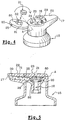
- the dispensing head used according to this embodiment is shown in the perspective view of Figure 3.
- the user closes the flap 23. It controls the actuation of the pump 13 by pressing the surface 22 of the dispensing head, thereby causing the product P to exit through the pump rod 14.
- the product P rushes into the channel 16 and enters the cavity 20, where it is brought into contact with the product block 21, and causes the dissolution or fragmentation of all or part of said block.
- the mixture obtained then leaves through the outlet orifice 17, via the channel portion 30.
- a grid 29 is arranged at the entrance to portion 30 of channel 16, so that prevent direct drive of the product block 21 towards the orifice outlet 17.
- the product block 21 can be dissolved or fragmented in its entirety at during the same use. Alternatively, the same block of product 21 is used for several distribution cycles of product P.
- the product P is contained directly in the rigid enclosure 10, inside which is sealingly mounted, but free behind the scenes, a follower piston 50 which, as the distribution of the product, rises in the rigid enclosure 10, under the effect of the depression resulting from the decrease in the volume of product, which decrease is not compensated by a corresponding air volume.
- Dispensing head 15 is also identical in all respects to that fitted to assembly 1 of the embodiment of FIG. 1. The operation of this embodiment is similar to that of the previous embodiment.
- the dispensing head 15 corresponding to the variant of FIG. 4 is distinguished from that of FIG. 3 in that the solid block of product is placed inside an openwork skirt 80 carried by the closure element 23.
- the skirt 80 comprises a plurality of slots 81 delimiting elastically deformable legs capable of imprison the product block 21 before its first use.
- the free end 82 of the skirt 80 comes substantially to the contact of the bottom of the cavity 20 so as to retain the product block 21 at inside the skirt 80, the product P contained in the container coming into contact with the solid block of product 21 via the open end of the skirt 80.
- the mixture of two products meanwhile, is directed to the outlet 17 via the axial slots 81.
- FIG. 5 differs from the previous one in that baffles 71 are provided in the channel 30 leading to the outlet orifice 17, so as to homogenize the mixture of the two products.
- baffles 71 are provided in the channel 30 leading to the outlet orifice 17, so as to homogenize the mixture of the two products.
- the closure element extends to the outlet orifice 17, thus delimiting in part, said channel portion 30.
- the dispensing head 15 comprises a body 4 intended to be fixedly mounted on a container.
- the container is equipped a pump of which an emerging rod (not shown) is intended for force fit into an axial end piece defining a channel 16.
- Channel 16 opens into a cavity 20 formed in a part 100 articulated relative to the body 4 around a fixed axis A.
- the cavity has an opening 24 which, in folded position of the moving part 100 (FIG. 6B) is in communication with a portion 30 of the channel 16, located downstream of the cavity 20.
- the portion 30 of the channel 16 leads to an outlet orifice 17 selectively closed by a valve in elastomer 101.
- the consumer rotates the moving part 100 around the axis A so as to release the opening 24.
- the opening 24 introduces then in the housing 20 a solid tablet 21 of a product with which the product contained in the container is intended to come into contact. She then folds the piece mobile 100.
- the device is then ready for use, the distribution taking place by actuation of the pump in response to an axial depression of the head distribution 15.
- the tablet 21 After the tablet 21 has completely dissolved, it can be easily replaced by proceeding as indicated above, the dispensing head being able, before place the new tablet to be passed under the tap to be cleaned.
- the dispensing head 15 comprises a body 4 intended to be fixedly mounted on a container.
- the container is equipped a pump of which an emerging rod (not shown) is intended for force fit into an axial end piece defining a channel 16.
- Channel 16 opens into a cavity 20, the lower part of which is delimited by a skirt discontinuous 106 formed by the body 4, in the extension of the channel 16.
- the upper part of the cavity 20 is formed by a piece 102 articulated relative to the body 4 around a fixed axis A, perpendicular to an axis X of the head 15.
- the lower part of the cavity 20 defines an opening 24.
- the movable part 102 comprises an axial skirt 105 in the vicinity of one end of which is arranged a grid 103 intended in the folded position of the movable part 102 to cover the opening 24, and ensure the maintenance of the patch 21 inside its housing 20.
- the dispensing head 15 also includes a cover 104 hinged on the body 4, opposite the moving part 102, about an axis B, parallel to the axis A.
- the cover 104 comprises an axial orifice 17 fitted with a valve 101 opening under product pressure.
- the consumer lifts the cover 104 by rotating it around axis B. It then lifts the intermediate piece 102 by making it pivot around the axis A. It then introduces a pellet 21 into the housing 20 through the opening 24. It folds the intermediate piece 102 around the axis A, then the cover 104 around the axis B. The device is then ready to be used.
- the tablet 21 After the tablet 21 has completely dissolved, it can be easily replaced by proceeding as indicated above, the dispensing head 15 being able, before putting in place of the new tablet be passed under the tap to be cleaned.
- the housing 20 receiving the pellet 21 solid product is formed just upstream of a valve 101 opening under the product pressure.
- the tablet 21 is introduced into the housing 20 via the orifice of exit of the product 17, after taking care, in particular by means of a tool adequate, to tilt the valve 101 around the axis A, so as to release the opening enough to let the tablet 21.
- This position for inserting the patch 21 into the housing 20 is shown in FIG. 8.
- the valve 101 After introduction of the patch 21 into the housing 20, the valve 101 resumes by elastic return to its closed position, so as to retain the tablet 21 to inside the housing 20.
- the product conveyed through channel 16 of the dispensing head 15 enters the cavity 20 where it is brought into contact with the product solid 21, which is dissolved more or less slowly.
- the valve 101 moves away from the edge delimiting the opening 17 by pivoting around the axis A.
- the valve 101 remains sufficiently close to the edge delimiting the opening 17 so that the pellet 21 cannot be driven with the mixing through the opening 17.
- a dispensing head 15 according to the last three embodiments which just described can also be used in combination with a container in the form of a tube or a tube bottle with compressible walls elastically, and for which, the exit of the product is caused by crushing reversibly the walls of the container.
- the assembly 1 comprises a first container 90 and a second container 91, each surmounted by a pump or a valve.
- the dispensing head 15 which covers them is able to control the actuation simultaneous of the two pumps or valves in response to a pressure exerted on the bearing surface 22 of the dispensing head.
- the distribution head is also in accordance with any of the embodiments described with reference to Figures 3-5, 6A-6b, 7A-7B, or 8. With this embodiment, the distribution of a mixture of a basic composition, itself formed by the mixture of two products packaged separately in each of containers 90 and 91, and a product in solid or semi-solid form packaged in the dispensing head 15.
Abstract
Description
La présente invention a trait à une tête de distribution et à un ensemble de conditionnement et de distribution équipé d'une telle tête de distribution.The present invention relates to a dispensing head and a set of packaging and distribution equipped with such a distribution head.
Dans le domaine de la cosmétique, et notamment du maquillage ou du soin de la peau, il est fréquent de réaliser des associations diverses, à partir d'une composition de base, notamment d'une composition de maquillage ou une composition hydratante, en phase aqueuse, avec des actifs, tels que de la vitamine C, de la vitamine A, ou tout autre actif communément utilisé pour ses vertus cosmétiques ou dermato pharmacologiques.In the field of cosmetics, and in particular make-up or skin care skin, it is common to make various associations, from a base composition, in particular a makeup composition or a hydrating composition, in aqueous phase, with active agents, such as vitamin C, vitamin A, or any other active ingredient commonly used for its cosmetic or dermatological pharmacological properties.
Certaines associations ne posent aucun problème dans la mesure où l'actif à associer à la composition est parfaitement stable, et ce de façon durable, quand il est incorporé dans ladite composition. Le problème se pose avec certaines associations où l'actif se dégrade rapidement dans le temps, notamment au contact de l'eau ou tout autre solvant contenu dans la composition de base.Certain associations do not pose any problem insofar as the assets to associate with the composition is perfectly stable, and this in a lasting manner, when it is incorporated into said composition. The problem arises with some associations where the asset degrades rapidly over time, particularly contact with water or any other solvent contained in the base composition.
En outre, il existe une demande pour un soin que l'on qualifie parfois de "soin à la carte, selon lequel l'utilisatrice choisit, en fonction des circonstances, de l'environnement, ou tout simplement en fonction des besoins de sa peau, le ou les actifs qu'elle souhaite associer à la composition de base.In addition, there is a demand for a treatment which is sometimes referred to as " card, according to which the user chooses, depending on the circumstances, to the environment, or simply according to the needs of his skin, the assets that it wishes to associate with the basic composition.
Des dispositifs d'un fonctionnement peu aisé et d'un coût de revient important sont décrits dans les documents US-A-5 249 712 ou US-A-3 593 894. Dans tous ces dispositifs, l'accessibilité à la cavité contenant le second produit au contact duquel le premier est produit est destiné à être amené se fait via un élément amovible vissé ou encliqueté sur la tête de distribution. De par cette configuration, le risque est grand pour que l'élément amovible se perde en cours de route. En outre, c'est précisément dans cet élément amovible qu'est ménagé l'orifice de sortie de la tête de distribution, ce qui pose des problèmes à l'ouverture dans la mesure où les doigts sont amenés à venir au contact d'une portion de la tête de distribution souillée par le produit, ou plutôt par le mélange des deux produits.Devices which are not easy to operate and which have a high cost price are described in documents US-A-5,249,712 or US-A-3,593,894. In all of these devices, accessibility to the cavity containing the second product in contact with which the first one is produced is intended to be brought in is done via a removable element screwed or snapped onto the dispensing head. Because of this configuration, the risk is large so that the removable element gets lost along the way. In addition, it is precisely in this removable element which is formed the outlet orifice of the head of distribution, which poses problems at the opening insofar as the fingers are brought into contact with a portion of the dispensing head contaminated by the product, or rather by the mixture of the two products.
Aussi, est-ce un des objets de l'invention que de fournir une tête de distribution, ainsi qu'un ensemble équipé d'une telle tête, et qui permette de façon simple et économique d'associer un ou plusieurs actifs avec une composition de base, et de les mettre en contact, seulement au moment de l'application du mélange sur la surface à traiter.Also, is it an object of the invention to provide a distribution head, as well as an assembly equipped with such a head, and which allows in a simple and economical to combine one or more assets with a basic composition, and put them in contact, only when the mixture is applied to the surface to be treated.
C'est un autre objet de l'invention que de fournir une tête de distribution, ainsi qu'un ensemble équipé d'une telle tête, et qui permette de choisir à volonté l'actif à associer à la composition de base.It is another object of the invention to provide a dispensing head, as well that a set equipped with such a head, and which allows to choose at will the active to associate with the basic composition.
C'est encore un autre objet de l'invention que de fournir une tête de distribution, ainsi qu'un ensemble équipé d'une telle tête, qui soit simple à utiliser, et lavable, notamment à chaque changement d'actif.It is yet another object of the invention to provide a dispensing head, as well as a set equipped with such a head, which is simple to use and washable, in particular at each change of asset.
D'autres objets encore apparaítront dans la description détaillée qui suit. Still other objects will appear in the detailed description which follows.
Selon l'invention, ces objets sont atteints en réalisant une tête de distribution montée, ou destinée à être montée fixement sur un récipient contenant un premier produit, notamment cosmétique ou de soin, ladite tête de distribution comprenant un passage débouchant sur au moins un orifice de sortie du produit, ledit passage traversant une cavité située en amont de l'orifice de sortie et dans laquelle est disposée un second produit sous forme solide ou semi solide, de manière à être mis en contact avec le premier produit lors de la distribution de ce dernier via ledit passage, ladite cavité comportant une ouverture accessible, depuis l'extérieur de ladite tête, via au moins un élément mobile articulé autour d'un axe.According to the invention, these objects are achieved by producing a dispensing head mounted, or intended to be fixedly mounted on a container containing a first product, in particular cosmetic or care product, said dispensing head comprising a passage leading to at least one product outlet orifice, said passage passing through a cavity located upstream of the outlet orifice and in which is arranged a second product in solid or semi-solid form, so as to be put in contact with the first product during the distribution of the latter via said passage, said cavity comprising an accessible opening, from outside of said head, via at least one mobile element articulated around an axis.
Selon l'invention, l'élément mobile peut, outre l'accès à l'ouverture de la cavité (notamment en vue de la mise en place du second produit) jouer d'autres rôles. II peut notamment faire office de clapet équipant l'orifice de sortie de la tête de distribution. Il peut également former la cavité contenant le second produit. Il peut délimiter tout ou partie du passage situé en aval de ladite cavité. Enfin, il peut assurer l'immobilisation du second produit à l'intérieur de la cavité.According to the invention, the mobile element can, in addition to access to the opening of the cavity (especially with a view to setting up the second product) play other roles. II can in particular act as a valve equipping the outlet orifice of the head distribution. It can also form the cavity containing the second product. he can delimit all or part of the passage located downstream of said cavity. Finally, he can ensure the immobilization of the second product inside the cavity.
La tête de distribution peut être réalisée en une seule pièce obtenue de moulage. Le coût de revient est faible et son fonctionnement, en particulier la mise en place d'un nouveau bloc dudit second produit, est des plus aisés, et ce, sans risque de se salir les doigts de manière démesurée.The dispensing head can be produced in a single piece obtained from molding. The cost price is low and its operation, in particular the establishment of a new block of said second product, is very easy, and this, without risk of getting your fingers dirty excessively.
Ainsi, l'utilisatrice choisit à volonté l'actif qu'elle souhaite associer à la composition de base. Elle peut en changer chaque fois qu'elle le souhaite, soit après utilisation complète de l'actif en place dans la cavité, soit en cours d'utilisation d'un actif particulier. A chaque changement, elle peut passer la tête de distribution sous le robinet de manière à débarrasser la cavité ainsi que les canaux environnants de tout résidu solide pouvant y séjourner, évitant ainsi le colmatage des canaux de la tête de distribution, et/ou la pollution d'un actif par un autre.Thus, the user chooses at will the asset that she wishes to associate with the composition basic. She can change it whenever she wants, either after use full of active in place in the cavity, either in use of an active particular. At each change, it can pass the distribution head under the tap so as to rid the cavity and the surrounding channels of any solid residue which may remain there, thus avoiding clogging of the channels of the distribution head, and / or the pollution of one asset by another.
De préférence, l'élément mobile est mobile par rapport à l'orifice de sortie du produit. De préférence encore, il est mobile par rapport à une portion dudit passage située en aval de la cavité (par rapport au sens d'écoulement du produit). Ces caractéristiques distinguent le dispositif selon la présente invention des dispositifs décrits précédemment dans lesquels la partie du passage située an aval de la cavité, ainsi que l'orifice de sortie sont formés précisément dans la pièce mobile.Preferably, the movable element is movable relative to the outlet orifice of the product. More preferably, it is movable relative to a portion of said passage located downstream of the cavity (relative to the direction of flow of the product). These characteristics distinguish the device according to the present invention from previously described devices in which the part of the passage located an downstream of the cavity, as well as the outlet orifice are formed precisely in the part mobile.
De préférence, l'élément mobile est destiné, au moins en position de repos, à obturer de manière étanche ladite ouverture. La position de repos s'entend d'une position dans laquelle l'élément mobile n'est pas soumis à une contrainte sensible, en particulier résultant de la pression du produit.Preferably, the movable element is intended, at least in the rest position, to sealing said opening. The rest position means position in which the movable element is not subjected to significant stress, in particular resulting from the pressure of the product.
Dans la configuration selon laquelle l'élément mobile délimite le logement destiné à recevoir le second produit, l'élément mobile peut être déplacé entre une première position dans laquelle ladite ouverture est en communication avec l'orifice de sortie, et une seconde position dans laquelle l'ouverture est accessible en vue de la mise en place notamment d'un bloc dudit second produit. In the configuration according to which the movable element delimits the housing intended to receive the second product, the mobile element can be moved between a first position in which said opening is in communication with the outlet, and a second position in which the opening is accessible for the establishment in particular of a block of said second product.
Le second produit sous forme solide peut être sous forme d'une poudre compactée, d'un gel, d'une crème, d'une gomme, ou d'un élément enrobé d'une membrane apte à se dissoudre ou éclater sous la pression de la composition de base, l'essentiel étant que le second produit puisse, avant d'être dissout dans la composition de base, ou entraíné de manière fragmentaire par cette dernière, séjourner de manière localisée à l'intérieur de la cavité en dépit du passage qui la traverse. A titre d'autre exemple, le second produit peut être contenu, par exemple sous forme d'une poudre, à l'intérieur d'un support poreux, notamment une mousse à cellules ouvertes ou semi ouvertes, un tissé ou un non tissé, ou d'un fritté.The second product in solid form can be in the form of a powder compacted, gel, cream, gum, or coated with membrane capable of dissolving or bursting under the pressure of the composition of basis, the main thing being that the second product can, before being dissolved in the basic composition, or trained in a fragmentary way by the latter, stay locally inside the cavity despite the passage which crosses. As another example, the second product can be contained, for example in the form of a powder, inside a porous support, in particular a open cell or semi open cell foam, woven or non-woven, or sintered.
Des moyens, notamment sous forme de chicanes, de réducteurs, ou de brise-jets, peuvent être prévus entre la cavité et l'orifice de sortie, de manière à favoriser le = mélange du premier produit avec le second produit. De tels moyens permettent en outre d'éviter que le bloc de produit sous forme solide soit entraíné tel quel vers l'orifice de sortie. Cette dernière fonction peut également être assurée au moyen d'un organe, notamment sous forme d'une grille, disposé entre la cavité et l'orifice de sortie de manière à retenir le bloc de second produit sous forme solide ou semi solide, à l'intérieur de la cavité.Means, in particular in the form of baffles, reducers, or jet breakers, can be provided between the cavity and the outlet, so as to favor the = mixing the first product with the second product. Such means allow in addition to avoiding that the block of product in solid form is entrained as is towards the outlet. This latter function can also be ensured by means of a member, in particular in the form of a grid, disposed between the cavity and the orifice output so as to retain the block of second product in solid or semi form solid, inside the cavity.
La cavité contenant le second produit peut être à plus ou moins grande distance de l'orifice de sortie.The cavity containing the second product can be more or less distant of the outlet.
L'élément de fermeture peut être sur une face différente de la face sur laquelle débouche l'orifice de sortie, ou sur la même face. Dans ce dernier cas, on peut prévoir que la cavité contenant le produit solide soit immédiatement en amont d'un clapet équipant l'orifice de sortie, et s'ouvrant sous la pression du produit, le clapet pouvant alors constituer l'élément mobile visé par la présente invention. Selon ce mode de réalisation, le produit est introduit dans la cavité au travers du clapet, par exemple en en forçant l'ouverture au moyen d'un outil approprié ou avec un doigt. De même, à l'utilisation, le mélange constitué des premier et second produits sort via le clapet, lequel s'ouvre sous la pression du mélange.The closure element may be on a face different from the face on which opens the outlet, or on the same side. In the latter case, we can provide that the cavity containing the solid product is immediately upstream of a valve fitted to the outlet orifice, and opening under product pressure, the valve can then constitute the mobile element targeted by the present invention. According to what embodiment, the product is introduced into the cavity through the valve, by example by forcing the opening with a suitable tool or with a finger. Similarly, in use, the mixture consisting of the first and second products leaves via the valve, which opens under the pressure of the mixture.
Selon un mode de réalisation particulier, l'élément mobile est constitué d'un volet articulé au moyen d'une charnière film, ou de tout autre type d'articulation. Un moyen de verrouillage, de type à encliquetage, peut être prévu de manière à verrouiller l'élément mobile en position fermée.According to a particular embodiment, the mobile element consists of a flap articulated by means of a film hinge, or any other type of articulation. A locking means, of the snap type, can be provided so as to lock the movable element in the closed position.
Le second produit sous forme solide ou semi solide peut être contenu à l'intérieur d'un logement ajouré porté par l'élément mobile, et destiné, en position fermée de l'élément mobile, à se loger dans ladite cavité. Une extrémité du logement ajouré peut être fermée par une portion de surface de l'élément mobile, l'autre extrémité étant ouverte pour l'introduction de l'élément solide, et fermée par le fond de la cavité, en position fermée de l'élément mobile. Des fentes s'étendant axialement entre les deux extrémités du logement permettant au premier produit de venir en contact avec le produit solide contenu dans le logement et/ou au mélange des deux produits, de s'acheminer vers l'orifice de sortie.The second product in solid or semi-solid form can be contained inside an openwork housing carried by the movable element, and intended, in the closed position of the movable element, to be housed in said cavity. One end of the openwork housing can be closed by a surface portion of the movable element, the other end being open for the introduction of the solid element, and closed by the bottom of the cavity, in the closed position of the movable element. Axially extending slots between the two ends of the housing allowing the first product to come in contact with the solid product contained in the housing and / or the mixture of two products, to move towards the exit orifice.
La tête de distribution selon l'invention peut être conformée sous forme d'un bouton poussoir apte à permettre l'actionnement d'un élément de distribution, notamment d'une pompe ou d'une valve. Le ou les orifice(s) de sortie peuvent être formés à l'intérieur d'un organe de diffusion, faisant partie de la tête de distribution, et constitué notamment d'une grille, d'un fritté, d'une mousse, d'un clapet à ouverture commandée par la pression du produit, ou d'une buse, notamment tourbillonnaire. L'orifice de sortie peut être obturé par un clapet, notamment sous forme d'une lame en élastomère, apte à s'ouvrir sous la pression du produit, et à se refermer par rappel élastique, lorsque cesse la pression.The dispensing head according to the invention can be shaped as a push button adapted to allow actuation of a dispensing element, including a pump or a valve. The outlet (s) can be formed inside a diffusion member, forming part of the dispensing head, and consists in particular of a grid, a frit, a foam, a check valve opening controlled by the pressure of the product, or of a nozzle, in particular vortex. The outlet can be closed by a valve, especially under form of an elastomer blade, capable of opening under the pressure of the product, and to close by elastic return, when the pressure stops.
Selon la présente invention, on réalise également un ensemble de conditionnement et de distribution, comprenant au moins un récipient contenant un premier produit et équipé d'une tête de distribution selon l'invention.According to the present invention, a set of packaging and distribution, comprising at least one container containing a first product and equipped with a dispensing head according to the invention.
Le récipient peut être équipé d'un moyen de distribution, notamment d'une valve = ou d'une pompe, notamment sans reprise d'air, et dont la tête de distribution est destinée à assurer l'actionnement.The container can be equipped with a distribution means, in particular with a valve = or a pump, in particular without air intake, and whose distribution head is intended to ensure actuation.
Selon un mode de réalisation avantageux, le premier produit est contenu à l'intérieur du réservoir formé à l'intérieur du récipient, et délimité au moins en partie par une poche à parois souples, ou un piston.According to an advantageous embodiment, the first product is contained in the interior of the reservoir formed inside the container, and delimited at least in part by a pocket with flexible walls, or a piston.
Selon un autre mode de réalisation, l'ensemble selon l'invention comprend deux récipients, contenant chacun un premier produit, et équipés chacun d'un moyen de distribution, notamment d'une pompe ou d'une valve, ladite tête de distribution étant apte à commander l'actionnement simultané de chacun des moyens de distribution.According to another embodiment, the assembly according to the invention comprises two containers, each containing a first product, and each equipped with a means of distribution, in particular of a pump or a valve, said distribution head being able to control the simultaneous actuation of each of the means of distribution.
Selon encore un autre mode de réalisation, le récipient est constitué d'un tube ou d'un flacon à parois déformables, de manière à forcer la sortie du premier produit par une surpression résultant de la déformation des parois.According to yet another embodiment, the container consists of a tube or a bottle with deformable walls, so as to force the exit of the first product by an overpressure resulting from the deformation of the walls.
Avantageusement, le second produit sous forme solide contient au moins un actif cosmétique ou de soin, notamment de la vitamine C, de la vitamine A ou de l'acide Kojique.Advantageously, the second product in solid form contains at least one active cosmetic or care products, in particular vitamin C, vitamin A or acid Kojic.
L'invention consiste, mises à part les dispositions exposées ci-dessus, en un certain nombre d'autres dispositions qui seront explicitées ci-après, à propos d'exemples de réalisation non limitatifs, décrits en référence aux figures annexées, parmi lesquelles:
- la figure 1 illustre un premier mode de réalisation d'un ensemble de conditionnement et de distribution selon l'invention ;
- la figure 2 illustre un second mode de réalisation d'un ensemble de conditionnement et de distribution selon l'invention ;
- les figures 3-5, 6A-6B, 7A-7B, et 8 illustrent six modes de réalisation différents de la tête de distribution selon l'invention; et
- la figure 9 illustre un troisième mode de réalisation d'un ensemble de conditionnement et de distribution selon l'invention.
- FIG. 1 illustrates a first embodiment of a packaging and distribution assembly according to the invention;
- FIG. 2 illustrates a second embodiment of a packaging and distribution assembly according to the invention;
- Figures 3-5, 6A-6B, 7A-7B, and 8 illustrate six different embodiments of the dispensing head according to the invention; and
- FIG. 9 illustrates a third embodiment of a packaging and distribution assembly according to the invention.
L'ensemble 1 représenté à la figure 1 comprend une poche à parois souples 2
(formée d'un complexe multi-couches comportant une couche d'aluminium) dont
une extrémité est fermée par un fond 3 et dont l'autre extrémité présente un bord
libre délimitant une ouverture. A l'intérieur de ladite ouverture, est montée de
manière étanche une pièce intermédiaire 5. Le montage étanche de la pièce
intermédiaire 5 sur la poche est réalisé par collage ou soudure entre la surface
intérieure du bord libre de la poche et la surface externe d'une jupe latérale 6
formée par la pièce intermédiaire 5. La jupe latérale 6 comporte un bourrelet
annulaire 8 apte à coopérer par claquage avec une gorge correspondante 9
formée sur la surface interne d'une enceinte rigide 10 en polypropylène. Le fond
de l'enceinte 10 est pourvu d'un trou 11 permettant une entrée d'air dans le
volume compris entre l'enceinte rigide 10 et la poche à parois souples 2,
permettant ainsi de compenser la diminution de volume de la poche résultant de la
distribution d'une dose de produit.The assembly 1 represented in FIG. 1 comprises a pocket with flexible walls 2
(formed of a multi-layer complex comprising an aluminum layer) of which
one end is closed by a bottom 3 and the other end of which has an edge
free delimiting an opening. Inside said opening, is mounted
sealing an
La poche contient une composition hydratante P pour le corps.The pocket contains a hydrating composition P for the body.
La pièce intermédiaire 5, comprend une cheminée axiale 12 dans laquelle est
montée à force une pompe opérant sans reprise d'air 13. La pompe comporte une
tige émergente 14 sur laquelle est montée (via un châssis 4) une tête de
distribution 15 en polypropylène, comportant un canal 16 reliant la tige émergente
14 à un orifice de sortie 17. Le canal 16 reliant la tige émergeante 14 à l'orifice de
sortie traverse une cavité 20 formée dans la tête de distribution, et à l'intérieur de
laquelle est disposé un bloc solide 21 à base de vitamine C. De l'autre côté de la
cavité 20, le canal 16 se prolonge par une portion 30 débouchant sur l'orifice de
sortie 17.The
Du côté de la surface 22 de la tête de distribution destinée à l'actionnement de la
pompe 15, la tête de distribution 15 comporte un volet 23 destiné à obturer de
manière réversible une ouverture 24 délimitée par un bord de ladite cavité 20. Le
volet 23 est articulé autour d'un axe A par rapport au châssis 4 de la tête de
distribution 15. Selon ce mode de réalisation, l'axe d'articulation A est formé par
une charnière film. A l'opposé de l'axe d'articulation A, le volet 23 comporte une
bourrelet 25 apte à assurer un verrouillage par encliquetage du volet 23 en
position fermée. La tête de distribution utilisée selon ce mode de réalisation est
représentée dans la vue en perspective de la figure 3.On the side of the
Ainsi, après avoir introduit le bloc solide 21 dans la cavité 20, l'utilisatrice referme
le volet 23. Elle commande l'actionnement de la pompe 13 en appuyant sur la
surface 22 de la tête de distribution, provoquant ainsi la sortie du produit P au
travers de la tige de pompe 14. Le produit P s'engouffre dans le canal 16 et
pénètre dans la cavité 20, où il est mis en contact avec le bloc de produit 21, et
provoque la dissolution ou fragmentation de tout ou partie dudit bloc. Le mélange
obtenu sort alors au travers de l'orifice de sortie 17, via la portion de canal 30. Une
grille 29 est disposée à l'entrée de la portion 30 du canal 16, de manière à
empêcher l'entraínement direct du bloc de produit 21 en direction de l'orifice de
sortie 17. Le bloc de produit 21 peut être dissout ou fragmenté dans sa totalité au
cours d'une même utilisation. Alternativement, un même bloc de produit 21 est
utilisé pour plusieurs cycles de distribution du produit P.Thus, after having introduced the
Dans le mode de réalisation de la figure 2, le produit P est contenu directement
dans l'enceinte rigide 10, à l'intérieur de laquelle est monté de manière étanche,
mais libre en coulisse, un piston suiveur 50 qui, au fur et à mesure de la
distribution du produit, remonte dans l'enceinte rigide 10, sous l'effet de la
dépression résultant de la diminution du volume de produit, laquelle diminution
n'est pas compensée par un volume d'air correspondant. La tête de distribution 15
est par ailleurs en tous points identiques à celle équipant l'ensemble 1 du mode de
réalisation de la figure 1. Le fonctionnement de ce mode de réalisation est
similaire à celui du mode de réalisation précédent.In the embodiment of FIG. 2, the product P is contained directly
in the
La tête de distribution 15 correspondant à la variante de la figure 4 se distingue de
celle de la figure 3 en ce que le bloc solide de produit est disposé à l'intérieur
d'une jupe ajourée 80 portée par l'élément de fermeture 23. La jupe 80 comporte
une pluralité de fentes 81 délimitant des pattes élastiquement déformables aptes à
emprisonner le bloc de produit 21 avant sa première utilisation. Conformément à
ce qui est représenté en référence au mode de réalisation de la figure 6, en
refermant le couvercle 23, l'extrémité libre 82 de la jupe 80 vient sensiblement au
contact du fond de la cavité 20 de manière à retenir le bloc de produit 21 à
l'intérieur de la jupe 80, le produit P contenu dans le récipient venant au contact du
bloc solide de produit 21 via l'extrémité ouverte de la jupe 80. Le mélange des
deux produits, quant à lui, est dirigé vers l'orifice de sortie 17 via les fentes axiales
81.The dispensing
Le mode de réalisation de la figure 5 se distingue du précédent en ce que des
chicanes 71 sont prévues dans le canal 30 conduisant à l'orifice de sortie 17, de
manière à homogénéiser le mélange des deux produits. Pour des raisons tenant
au moulage d'une telle pièce, et également à son nettoyage, notamment de la
portion de canal 30 comportant les chicanes, il est préférable de prévoir que
l'élément de fermeture s'étende jusqu'à l'orifice de sortie 17, délimitant ainsi en
partie, ladite portion de canal 30. Le fonctionnement de la tête de distribution 15
selon ce mode de réalisation est conforme au fonctionnement des modes de
réalisation précédents.The embodiment of FIG. 5 differs from the previous one in that
baffles 71 are provided in the
Dans le mode de réalisation des figures 6A-6B, la tête de distribution 15 comprend
un corps 4 destiné à être monté fixement sur un récipient. Le récipient est équipé
d'une pompe dont une tige émergeante (non représentée) est destinée à
s'emmancher à force dans un embout axial délimitant un canal 16. Le canal 16
débouche dans une cavité 20 formée dans une pièce 100 articulée par rapport au
corps 4 autour d'un axe fixe A. La cavité comporte une ouverture 24 qui, en
position rabattue de la pièce mobile 100 (figure 6B) est en communication avec
une portion 30 du canal 16, située en aval de la cavité 20. La portion 30 du canal
16 débouche sur un orifice de sortie 17 obturé de façon sélective par un clapet en
élastomère 101.In the embodiment of FIGS. 6A-6B, the dispensing
A l'utilisation, la consommatrice fait pivoter la pièce mobile 100 autour de l'axe A
de manière à dégager l'ouverture 24. Au travers de l'ouverture 24, elle introduit
alors dans le logement 20 une pastille solide 21 d'un produit avec lequel le produit
contenu dans le récipient est destiné à venir au contact. Elle rabat ensuite la pièce
mobile 100. Le dispositif est alors prêt à l'utilisation, la distribution s'opérant par
actionnement de la pompe en réponse à un enfoncement axial de la tête de
distribution 15. In use, the consumer rotates the moving
Après dissolution totale de la pastille 21, celle-ci peut être remplacée aisément en
procédant comme indiqué ci-dessus, la tête de distribution pouvant, avant mise en
place de la nouvelle pastille être passée sous le robinet pour être nettoyée.After the
Dans le mode de réalisation des figures 7A-7B, la tête de distribution 15 comprend
un corps 4 destiné à être monté fixement sur un récipient. Le récipient est équipé
d'une pompe dont une tige émergeante (non représentée) est destinée à
s'emmancher à force dans un embout axial délimitant un canal 16. Le canal 16
débouche dans une cavité 20 dont la partie basse est délimitée par une jupe
discontinue 106 formée par le corps 4, dans le prolongement du canal 16. La
partie haute de la cavité 20 est formée par une pièce 102 articulée par rapport au
corps 4 autour d'un axe fixe A, perpendiculaire à un axe X de la tête 15.In the embodiment of FIGS. 7A-7B, the dispensing
La partie basse de la cavité 20 délimite une ouverture 24. La pièce mobile 102
comprend une jupe axiale 105 au voisinage d'une extrémité de laquelle est
disposée une grille 103 destinée en position rabattue de la pièce mobile 102 à
recouvrir l'ouverture 24, et à assurer le maintien de la pastille 21 à l'intérieur de
son logement 20.The lower part of the
La tête de distribution 15 comprend également un couvercle 104 articulé sur le
corps 4, à l'opposé de la pièce mobile 102, autour d'un axe B, parallèle à l'axe A.
Le couvercle 104 comprend un orifice axial 17 équipé d'un clapet 101 s'ouvrant
sous la pression du produit.The dispensing
A l'utilisation, la consommatrice soulève le couvercle 104 en le faisant pivoter
autour de l'axe B. Elle soulève ensuite la pièce intermédiaire 102 en la faisant
pivoter autour de l'axe A. Elle introduit alors une pastille 21 dans le logement 20
au travers de l'ouverture 24. Elle rabat la pièce intermédiaire 102 autour de l'axe
A, puis le couvercle 104 autour de l'axe B. Le dispositif est alors prêt pour être
utilisé.In use, the consumer lifts the
Après dissolution totale de la pastille 21, celle-ci peut être remplacée aisément en
procédant comme indiqué ci-dessus, la tête de distribution 15 pouvant, avant mise
en place de la nouvelle pastille être passée sous le robinet pour être nettoyée.After the
Dans le mode de réalisation de la figure 8, le logement 20 recevant la pastille 21
de produit solide est formé en juste en amont d'un clapet 101 s'ouvrant sous la
pression du produit. La pastille 21 est introduite dans le logement 20 via l'orifice de
sortie du produit 17, après avoir pris soin, notamment au moyen d'un outil
adéquat, de faire basculer le clapet 101 autour de l'axe A, de manière à dégager
suffisamment l'ouverture pour laisser passer la pastille 21. Cette position
d'introduction de la pastille 21 dans le logement 20 est représentée à la figure 8.In the embodiment of Figure 8, the
Après introduction de la pastille 21 dans le logement 20, le clapet 101 reprend par
rappel élastique sa position de fermeture, de manière à retenir la pastille 21 à
l'intérieur du logement 20. A l'utilisation, le produit acheminé par le canal 16 de la
tête de distribution 15, entre dans la cavité 20 où il est mis au contact du produit
solide 21, lequel est dissout de manière plus ou moins lente . Sous la pression du
mélange, le clapet 101 s'écarte du bord délimitant l'ouverture 17 en pivotant
autour de l'axe A. Toutefois, le clapet 101 reste suffisamment proche du bord
délimitant l'ouverture 17 pour que la pastille 21 ne puisse être entraíné avec le
mélange au travers de l'ouverture 17.After introduction of the
Une tête de distribution 15 selon les trois derniers modes de réalisation qui
viennent d'être décrits peut également être utilisée en combinaison avec un
récipient sous forme d'un tube ou d'un flacon tube à parois compressibles
élastiquement, et pour lequel, la sortie du produit est provoquée en écrasant de
manière réversible les parois du récipient.A dispensing
Dans le mode de réalisation de la figure 9, l'ensemble 1 comprend un premier
récipient 90 et un second récipient 91, chacun surmontés d'une pompe ou d'une
valve. La tête de distribution 15 qui les coiffe est apte à commander l'actionnement
simultané des deux pompes ou valves en réponse à une pression exercée sur la
surface d'appui 22 de la tête de distribution. La tête de distribution est par ailleurs
conforme à l'un quelconque des modes de réalisation décrits en référence aux
figures 3-5, 6A-6b, 7A-7B, ou 8. Avec ce mode de réalisation, on permet la
distribution d'un mélange d'une composition de base, elle même formée par le
mélange de deux produits conditionnés de manière séparée dans chacun des
récipients 90 et 91, et d'un produit sous forme solide ou semi solide conditionné
dans la tête de distribution 15.In the embodiment of FIG. 9, the assembly 1 comprises a
Dans la description détaillée qui précède, il a été fait référence à des modes de réalisation préférés de l'invention. Il est évident que des variantes peuvent y être apportées sans s'écarter de l'esprit de l'invention telle que revendiquée ci-après.In the foregoing detailed description, reference has been made to modes of preferred embodiments of the invention. Obviously there may be variations made without departing from the spirit of the invention as claimed below.
Claims (19)
caractérisée en ce que l'élément mobile (23, 101, 104) est destiné, au moins en position de repos, à obturer de manière étanche ladite ouverture (17, 24).Dispensing head according to any one of claims 1 to 3
characterized in that the mobile element (23, 101, 104) is intended, at least in the rest position, to seal said opening (17, 24).
caractérisée en ce que des moyens, notamment sous forme de chicanes (71), de réducteurs, ou de brise-jets, sont prévus entre la cavité (20) et l'orifice de sortie (17), de manière à favoriser le mélange du premier produit (P) avec le second produit.Dispensing head (15) according to any one of claims 1 to 4
characterized in that means, in particular in the form of baffles (71), reducers, or jet breakers, are provided between the cavity (20) and the outlet orifice (17), so as to promote mixing of the first product (P) with the second product.
caractérisée en ce que des moyens, notamment sous forme d'une grille (29, 103), sont prévus entre la cavité (20) et l'orifice de sortie (17) pour retenir le second produit (21) sous forme solide ou semi solide, à l'intérieur de la cavité (20).Dispensing head (15) according to any one of claims 1 to 5
characterized in that means, in particular in the form of a grid (29, 103), are provided between the cavity (20) and the outlet orifice (17) for retaining the second product (21) in solid or semi form solid, inside the cavity (20).
caractérisée en ce que l'élément mobile est constitué d'un couvercle (23) articulé sur ladite tête de distribution (15) ou d'un clapet (101) à ouverture commandée par la pression.Dispensing head (15) according to any one of claims 1 to 6
characterized in that the movable element consists of a cover (23) articulated on said dispensing head (15) or of a valve (101) with opening controlled by pressure.
caractérisé en ce que ladite cavité (20) est formée au moins en partie par l'élément mobile (100, 101, 102).Dispensing head according to any one of claims 1 to 6
characterized in that said cavity (20) is formed at least in part by the movable element (100, 101, 102).
caractérisée en ce qu'elle comprend un premier élément (102) mobile par rapport au châssis (4) autour d'un axe d'articulation (A) et d'un second élément (104) mobile par rapport audit châssis (4) et par rapport au premier élément mobile (102), ledit second élément mobile (104) comportant ledit orifice de sortie (17). Dispensing head according to any one of claims 1 to 7
characterized in that it comprises a first element (102) movable relative to the chassis (4) around an axis of articulation (A) and a second element (104) movable relative to said chassis (4) and relative to the first movable member (102), said second movable member (104) having said outlet port (17).
caractérisée en ce que le second produit sous forme solide ou semi solide (21) est contenu à l'intérieur d'un logement ajouré (80) porté par l'élément mobile (23), et destiné, en position fermée de l'élément mobile (23), à se loger dans ladite cavité (20).Dispensing head (15) according to any one of claims 1 to 10
characterized in that the second product in solid or semi-solid form (21) is contained inside an openwork housing (80) carried by the mobile element (23), and intended, in the closed position of the element mobile (23), to be housed in said cavity (20).
caractérisé en ce que le premier produit est contenu à l'intérieur d'un réservoir (2, 10) formé à l'intérieur du récipient (10), et délimité au moins en partie par une poche à parois souples (2), ou un piston (50).Packaging and distribution assembly (1) according to claim 15
characterized in that the first product is contained inside a reservoir (2, 10) formed inside the container (10), and delimited at least in part by a pocket with flexible walls (2), or a piston (50).
Applications Claiming Priority (2)
| Application Number | Priority Date | Filing Date | Title |
|---|---|---|---|
| FR0008083 | 2000-06-23 | ||
| FR0008083A FR2810643B1 (en) | 2000-06-23 | 2000-06-23 | DISPENSING HEAD, AND PACKAGING AND DISPENSING ASSEMBLY PROVIDED WITH SUCH A HEAD |
Publications (2)
| Publication Number | Publication Date |
|---|---|
| EP1166885A1 true EP1166885A1 (en) | 2002-01-02 |
| EP1166885B1 EP1166885B1 (en) | 2009-08-26 |
Family
ID=8851613
Family Applications (1)
| Application Number | Title | Priority Date | Filing Date |
|---|---|---|---|
| EP01401488A Expired - Lifetime EP1166885B1 (en) | 2000-06-23 | 2001-06-08 | Dispensing head and a packaging and dispensing unit provided with such a head |
Country Status (8)
| Country | Link |
|---|---|
| US (1) | US6622890B2 (en) |
| EP (1) | EP1166885B1 (en) |
| JP (1) | JP3848852B2 (en) |
| AT (1) | ATE440672T1 (en) |
| CA (1) | CA2351213C (en) |
| DE (1) | DE60139659D1 (en) |
| ES (1) | ES2330832T3 (en) |
| FR (1) | FR2810643B1 (en) |
Cited By (7)
| Publication number | Priority date | Publication date | Assignee | Title |
|---|---|---|---|---|
| EP1498362A1 (en) * | 2002-03-29 | 2005-01-19 | Tani Industry Co., Ltd | Packaging container with contents mixing structure |
| EP3049190A1 (en) * | 2013-09-26 | 2016-08-03 | S.C. Johnson & Son, Inc. | System for spraying a dispensable material and methods relating thereto |
| WO2016187610A1 (en) * | 2015-05-21 | 2016-11-24 | Richard Ma | Fluid pump sterilization apparatus and method |
| CN108928553A (en) * | 2017-05-24 | 2018-12-04 | 卢姆森股份公司 | Liquid substance container and application method with hermetic seal system |
| CN108945790A (en) * | 2017-05-24 | 2018-12-07 | 卢姆森股份公司 | There are the container and application method of the flowing material of moveable bottom and leak-tight system |
| EP3441324A1 (en) | 2017-08-09 | 2019-02-13 | Aptar Radolfzell GmbH | Liquid dispenser for applying a liquid with an additional storage device for an additional medium |
| EP3368228A4 (en) * | 2015-10-28 | 2019-07-03 | Crossford International, LLC | Hand-held solid chemical applicator |
Families Citing this family (21)
| Publication number | Priority date | Publication date | Assignee | Title |
|---|---|---|---|---|
| US7213728B2 (en) * | 2004-06-24 | 2007-05-08 | S.C. Johnson & Son, Inc. | Time delay and indicator actuator assembly for aerosol containers |
| FR2875110B1 (en) | 2004-09-10 | 2006-12-22 | Oreal | DEVICE FOR APPLYING A PRODUCT PROVIDED WITH A REMOVABLE APPLICATION MEMBER |
| JP4729569B2 (en) * | 2005-06-10 | 2011-07-20 | 河野樹脂工業株式会社 | Foam ejection container and structure of pump head of the foam ejection container |
| US7784647B2 (en) * | 2005-08-16 | 2010-08-31 | Zynon Technologies, Llc | Actuators for fluid-dispenser containers and containers including such actuators |
| US20070040296A1 (en) * | 2005-08-16 | 2007-02-22 | Moore Singleton C | Soap saver |
| US8974410B2 (en) | 2006-10-30 | 2015-03-10 | Vidacare LLC | Apparatus and methods to communicate fluids and/or support intraosseous devices |
| EP2772313A4 (en) * | 2007-03-09 | 2014-09-03 | Kao Corp | Pump-equipped container and dual discharge container |
| USD588916S1 (en) | 2008-04-02 | 2009-03-24 | Mary Kay Inc. | Container |
| DE102009021501B4 (en) * | 2009-05-15 | 2011-09-01 | F. Holzer Gmbh | Reservoir and use of the reservoir |
| US8882720B2 (en) * | 2009-10-01 | 2014-11-11 | L'oreal | Skin formulation dispenser for use with or as part of a sonic applicator |
| US8662409B2 (en) * | 2009-10-26 | 2014-03-04 | S.C. Johnson & Son, Inc. | Multi-layered active ingredient dispenser |
| USD657242S1 (en) | 2010-01-14 | 2012-04-10 | S.C. Johnson & Son, Inc. | Container with nozzle |
| USD648216S1 (en) | 2010-01-14 | 2011-11-08 | S.C. Johnson & Son, Inc. | Actuator nozzle for a diffusion device |
| US9072876B2 (en) * | 2010-08-05 | 2015-07-07 | Medicis Pharmaceutical Corporation | Pump systems and methods for storing and dispensing a plurality of precisely measured unit-doses of imiquimod cream |
| FR2971681B1 (en) * | 2011-02-21 | 2013-12-06 | Oreal | PACKAGING AND MIXING ASSEMBLY FOR COSMETIC PRODUCTS |
| KR101280934B1 (en) * | 2011-11-01 | 2013-07-02 | 강성일 | Vacuum vessel and its manufacturing methods |
| WO2018083092A1 (en) * | 2016-11-01 | 2018-05-11 | Koninklijke Philips N.V. | Stain removal accessory |
| IL250680B (en) * | 2017-02-20 | 2018-10-31 | Matok Vkal Ltd | Packaging container with a pump dispenser |
| US11478817B2 (en) * | 2018-06-21 | 2022-10-25 | Silgan Dispensing Systems Corporation | Dispensing assembly including an additive mixing device |
| CA3166476A1 (en) * | 2020-01-29 | 2021-08-05 | Over The Top Foods Inc. | Dispensation devices and methods of manufacture and use thereof |
| CN112978019B (en) * | 2021-03-08 | 2023-01-13 | 深圳蔓狮科技有限公司 | Application method of comparable anti-hair loss shampoo device |
Citations (10)
| Publication number | Priority date | Publication date | Assignee | Title |
|---|---|---|---|---|
| CH310456A (en) * | 1953-06-03 | 1955-10-31 | Schostal Sa | Spray gun for liquid projection. |
| US3311263A (en) * | 1965-06-11 | 1967-03-28 | Pillsbury Co | Method and apparatus for striping and coloring extruded materials |
| US3593894A (en) | 1967-11-24 | 1971-07-20 | Colgate Palmolive Co | Aerosol dispenser attachment for incorporating additives into spray compositions |
| GB2204253A (en) * | 1987-04-30 | 1988-11-09 | Gerald Deeney | Spray or shower assemblies |
| FR2615826A1 (en) * | 1987-05-25 | 1988-12-02 | Oreal | Device for dispensing a mixture of a pasty substance and at least one pasty additive, particularly in the form of a striped strip, and dispensing head of such a device |
| FR2669243A1 (en) * | 1990-11-16 | 1992-05-22 | Givenchy Parfums | Mixer dispenser for at least two liquid products, especially for applications in the field of perfumery or of cosmetics |
| US5249712A (en) | 1988-10-28 | 1993-10-05 | Transphyto S.A. | Packaging for altering the composition of a liquid |
| FR2710612A1 (en) * | 1993-09-29 | 1995-04-07 | Kerplas Snc | Bottle for dispensing a product stored out of contact with the air |
| US5906316A (en) * | 1997-09-04 | 1999-05-25 | S. C. Johnson & Son, Inc. | Nozzle to dispense active material |
| FR2783694A1 (en) * | 1998-09-25 | 2000-03-31 | Dominique Chalon | Cleaning pistol for toilet bowls has reservoir containing treatment pastille subjected to water discharge flow |
Family Cites Families (5)
| Publication number | Priority date | Publication date | Assignee | Title |
|---|---|---|---|---|
| US4014463A (en) * | 1975-11-28 | 1977-03-29 | Kenics Corporation | Plural component dispenser |
| US5009342A (en) * | 1989-08-14 | 1991-04-23 | Mark R. Miller | Dual liquid spraying assembly |
| JP3290301B2 (en) * | 1994-06-28 | 2002-06-10 | 吉田工業株式会社 | Tube container |
| US6082588A (en) * | 1997-01-10 | 2000-07-04 | Lever Brothers Company, Division Of Conopco, Inc. | Dual compartment package and pumps |
| US6209757B1 (en) * | 2000-05-16 | 2001-04-03 | Charles Dumont | Squeezable mixing and dispensing container having removable attachable supply vessels |
-
2000
- 2000-06-23 FR FR0008083A patent/FR2810643B1/en not_active Expired - Fee Related
-
2001
- 2001-06-08 EP EP01401488A patent/EP1166885B1/en not_active Expired - Lifetime
- 2001-06-08 AT AT01401488T patent/ATE440672T1/en not_active IP Right Cessation
- 2001-06-08 ES ES01401488T patent/ES2330832T3/en not_active Expired - Lifetime
- 2001-06-08 DE DE60139659T patent/DE60139659D1/en not_active Expired - Lifetime
- 2001-06-18 CA CA002351213A patent/CA2351213C/en not_active Expired - Fee Related
- 2001-06-25 US US09/887,370 patent/US6622890B2/en not_active Expired - Fee Related
- 2001-06-25 JP JP2001192052A patent/JP3848852B2/en not_active Expired - Fee Related
Patent Citations (10)
| Publication number | Priority date | Publication date | Assignee | Title |
|---|---|---|---|---|
| CH310456A (en) * | 1953-06-03 | 1955-10-31 | Schostal Sa | Spray gun for liquid projection. |
| US3311263A (en) * | 1965-06-11 | 1967-03-28 | Pillsbury Co | Method and apparatus for striping and coloring extruded materials |
| US3593894A (en) | 1967-11-24 | 1971-07-20 | Colgate Palmolive Co | Aerosol dispenser attachment for incorporating additives into spray compositions |
| GB2204253A (en) * | 1987-04-30 | 1988-11-09 | Gerald Deeney | Spray or shower assemblies |
| FR2615826A1 (en) * | 1987-05-25 | 1988-12-02 | Oreal | Device for dispensing a mixture of a pasty substance and at least one pasty additive, particularly in the form of a striped strip, and dispensing head of such a device |
| US5249712A (en) | 1988-10-28 | 1993-10-05 | Transphyto S.A. | Packaging for altering the composition of a liquid |
| FR2669243A1 (en) * | 1990-11-16 | 1992-05-22 | Givenchy Parfums | Mixer dispenser for at least two liquid products, especially for applications in the field of perfumery or of cosmetics |
| FR2710612A1 (en) * | 1993-09-29 | 1995-04-07 | Kerplas Snc | Bottle for dispensing a product stored out of contact with the air |
| US5906316A (en) * | 1997-09-04 | 1999-05-25 | S. C. Johnson & Son, Inc. | Nozzle to dispense active material |
| FR2783694A1 (en) * | 1998-09-25 | 2000-03-31 | Dominique Chalon | Cleaning pistol for toilet bowls has reservoir containing treatment pastille subjected to water discharge flow |
Cited By (14)
| Publication number | Priority date | Publication date | Assignee | Title |
|---|---|---|---|---|
| EP1498362A4 (en) * | 2002-03-29 | 2008-12-10 | Tani Industry Co Ltd | Packaging container with contents mixing structure |
| EP1498362A1 (en) * | 2002-03-29 | 2005-01-19 | Tani Industry Co., Ltd | Packaging container with contents mixing structure |
| US10335817B2 (en) | 2013-09-26 | 2019-07-02 | S. C. Johnson & Son, Inc. | System for spraying a dispensable material and methods relating thereto |
| EP3049190A1 (en) * | 2013-09-26 | 2016-08-03 | S.C. Johnson & Son, Inc. | System for spraying a dispensable material and methods relating thereto |
| WO2016187610A1 (en) * | 2015-05-21 | 2016-11-24 | Richard Ma | Fluid pump sterilization apparatus and method |
| US10231579B2 (en) | 2015-05-21 | 2019-03-19 | Richard Ma | Fluid pump sterilization apparatus and method |
| EP3368228A4 (en) * | 2015-10-28 | 2019-07-03 | Crossford International, LLC | Hand-held solid chemical applicator |
| CN108945790A (en) * | 2017-05-24 | 2018-12-07 | 卢姆森股份公司 | There are the container and application method of the flowing material of moveable bottom and leak-tight system |
| CN108928553A (en) * | 2017-05-24 | 2018-12-04 | 卢姆森股份公司 | Liquid substance container and application method with hermetic seal system |
| CN108928553B (en) * | 2017-05-24 | 2021-08-24 | 卢姆森股份公司 | Liquid substance container with hermetic sealing system and method of use |
| CN108945790B (en) * | 2017-05-24 | 2021-09-28 | 卢姆森股份公司 | Container for fluid substances with a movable bottom and a gas-tight system and method of use |
| EP3441324A1 (en) | 2017-08-09 | 2019-02-13 | Aptar Radolfzell GmbH | Liquid dispenser for applying a liquid with an additional storage device for an additional medium |
| WO2019030055A1 (en) | 2017-08-09 | 2019-02-14 | Aptar Radolfzell Gmbh | Liquid dispenser for dispensing a liquid, having an additional reservoir for an additional medium |
| US11046503B2 (en) | 2017-08-09 | 2021-06-29 | Aptar Radolfzell Gmbh | Liquid dispenser for dispensing a liquid, having an additional reservoir for an additional medium |
Also Published As
| Publication number | Publication date |
|---|---|
| EP1166885B1 (en) | 2009-08-26 |
| ES2330832T3 (en) | 2009-12-16 |
| CA2351213A1 (en) | 2001-12-23 |
| CA2351213C (en) | 2006-05-09 |
| ATE440672T1 (en) | 2009-09-15 |
| US6622890B2 (en) | 2003-09-23 |
| FR2810643B1 (en) | 2002-09-06 |
| FR2810643A1 (en) | 2001-12-28 |
| DE60139659D1 (en) | 2009-10-08 |
| JP3848852B2 (en) | 2006-11-22 |
| US20020020715A1 (en) | 2002-02-21 |
| JP2002080082A (en) | 2002-03-19 |
Similar Documents
| Publication | Publication Date | Title |
|---|---|---|
| EP1166885B1 (en) | Dispensing head and a packaging and dispensing unit provided with such a head | |
| EP1355613B1 (en) | Device for spraying a cosmetic product | |
| EP1205400B1 (en) | Container provided with a dip tube and an applicator | |
| CA2397193C (en) | Device for packaging and application of a product, namely cosmetic | |
| EP1156300B1 (en) | Dosing tip and a container with such a dosing tip | |
| CA2248232C (en) | Dispenser head with improved air intake, and packaging and distribution assembly fitted with such a head | |
| EP1514492B1 (en) | Device for storing and dispensing a cosmetic product | |
| CA2398621C (en) | Kit for the packaging and application of a product, in particular a cosmetic | |
| CA2021856C (en) | Dispensing assembly for at least one fluid product, particularly cosmetic or pharmaceutical products | |
| EP1245506B1 (en) | Device for storing and dispensing of a cosmetic product | |
| CA2264256C (en) | Dispensing applicator head for a product such as a hair product and overall presentation of such an applicator head | |
| EP1035038B9 (en) | Unit for storing and dispensing a product under pressure, especially cosmetics | |
| EP1176103A1 (en) | Device for storing and dispensing a product, such as cosmetics | |
| EP0758615A1 (en) | Packaging and dispensing device | |
| EP1044625A1 (en) | Applying capsule and applicator assembly with such a capsule | |
| CA2305030A1 (en) | Device for triggering a distribution unit, specifically a valve, and assembly equipped with the said triggering device | |
| EP1382541B1 (en) | Device for storing and dispensing a product, particularly a cosmetic product | |
| FR2927513A1 (en) | CONTAINER, IN PARTICULAR FOR LIQUID COSMETICS, AND METHOD OF MANUFACTURING THE SAME | |
| FR2979808A1 (en) | COSMETIC PRODUCT APPLICATION DEVICE WITH A ROTARY APPLICATOR | |
| EP1293439A1 (en) | Storage and dispensing device for a liquid product | |
| CA2407213C (en) | Spraying device for application of at least on product on a substrate, namely a keratenized substrate such as skin | |
| EP1428455B2 (en) | Applicator, in particular for cosmetics | |
| EP1452109B1 (en) | Apparatus for applying a product like a cosmetic | |
| FR2783680A1 (en) | SINGLE-DOSE APPLICATOR | |
| EP1362525B1 (en) | Applicator device of roll-on type |
Legal Events
| Date | Code | Title | Description |
|---|---|---|---|
| PUAI | Public reference made under article 153(3) epc to a published international application that has entered the european phase |
Free format text: ORIGINAL CODE: 0009012 |
|
| AK | Designated contracting states |
Kind code of ref document: A1 Designated state(s): AT BE CH CY DE DK ES FI FR GB GR IE IT LI LU MC NL PT SE TR |
|
| AX | Request for extension of the european patent |
Free format text: AL;LT;LV;MK;RO;SI |
|
| 17P | Request for examination filed |
Effective date: 20020702 |
|
| AKX | Designation fees paid |
Free format text: AT BE CH CY DE DK ES FI FR GB GR IE IT LI LU MC NL PT SE TR |
|
| 17Q | First examination report despatched |
Effective date: 20070719 |
|
| GRAP | Despatch of communication of intention to grant a patent |
Free format text: ORIGINAL CODE: EPIDOSNIGR1 |
|
| GRAS | Grant fee paid |
Free format text: ORIGINAL CODE: EPIDOSNIGR3 |
|
| GRAA | (expected) grant |
Free format text: ORIGINAL CODE: 0009210 |
|
| AK | Designated contracting states |
Kind code of ref document: B1 Designated state(s): AT BE CH CY DE DK ES FI FR GB GR IE IT LI LU MC NL PT SE TR |
|
| REG | Reference to a national code |
Ref country code: GB Ref legal event code: FG4D Free format text: NOT ENGLISH |
|
| REG | Reference to a national code |
Ref country code: CH Ref legal event code: EP |
|
| REG | Reference to a national code |
Ref country code: IE Ref legal event code: FG4D Free format text: LANGUAGE OF EP DOCUMENT: FRENCH |
|
| REF | Corresponds to: |
Ref document number: 60139659 Country of ref document: DE Date of ref document: 20091008 Kind code of ref document: P |
|
| REG | Reference to a national code |
Ref country code: ES Ref legal event code: FG2A Ref document number: 2330832 Country of ref document: ES Kind code of ref document: T3 |
|
| PG25 | Lapsed in a contracting state [announced via postgrant information from national office to epo] |
Ref country code: AT Free format text: LAPSE BECAUSE OF FAILURE TO SUBMIT A TRANSLATION OF THE DESCRIPTION OR TO PAY THE FEE WITHIN THE PRESCRIBED TIME-LIMIT Effective date: 20090826 Ref country code: FI Free format text: LAPSE BECAUSE OF FAILURE TO SUBMIT A TRANSLATION OF THE DESCRIPTION OR TO PAY THE FEE WITHIN THE PRESCRIBED TIME-LIMIT Effective date: 20090826 Ref country code: SE Free format text: LAPSE BECAUSE OF FAILURE TO SUBMIT A TRANSLATION OF THE DESCRIPTION OR TO PAY THE FEE WITHIN THE PRESCRIBED TIME-LIMIT Effective date: 20090826 |
|
| NLV1 | Nl: lapsed or annulled due to failure to fulfill the requirements of art. 29p and 29m of the patents act | ||
| PG25 | Lapsed in a contracting state [announced via postgrant information from national office to epo] |
Ref country code: NL Free format text: LAPSE BECAUSE OF FAILURE TO SUBMIT A TRANSLATION OF THE DESCRIPTION OR TO PAY THE FEE WITHIN THE PRESCRIBED TIME-LIMIT Effective date: 20090826 |
|
| PG25 | Lapsed in a contracting state [announced via postgrant information from national office to epo] |
Ref country code: PT Free format text: LAPSE BECAUSE OF FAILURE TO SUBMIT A TRANSLATION OF THE DESCRIPTION OR TO PAY THE FEE WITHIN THE PRESCRIBED TIME-LIMIT Effective date: 20091228 Ref country code: CY Free format text: LAPSE BECAUSE OF FAILURE TO SUBMIT A TRANSLATION OF THE DESCRIPTION OR TO PAY THE FEE WITHIN THE PRESCRIBED TIME-LIMIT Effective date: 20090826 |
|
| REG | Reference to a national code |
Ref country code: IE Ref legal event code: FD4D |
|
| PG25 | Lapsed in a contracting state [announced via postgrant information from national office to epo] |
Ref country code: DK Free format text: LAPSE BECAUSE OF FAILURE TO SUBMIT A TRANSLATION OF THE DESCRIPTION OR TO PAY THE FEE WITHIN THE PRESCRIBED TIME-LIMIT Effective date: 20090826 Ref country code: IE Free format text: LAPSE BECAUSE OF FAILURE TO SUBMIT A TRANSLATION OF THE DESCRIPTION OR TO PAY THE FEE WITHIN THE PRESCRIBED TIME-LIMIT Effective date: 20090826 |
|
| PLBE | No opposition filed within time limit |
Free format text: ORIGINAL CODE: 0009261 |
|
| STAA | Information on the status of an ep patent application or granted ep patent |
Free format text: STATUS: NO OPPOSITION FILED WITHIN TIME LIMIT |
|
| 26N | No opposition filed |
Effective date: 20100527 |
|
| PG25 | Lapsed in a contracting state [announced via postgrant information from national office to epo] |
Ref country code: GR Free format text: LAPSE BECAUSE OF FAILURE TO SUBMIT A TRANSLATION OF THE DESCRIPTION OR TO PAY THE FEE WITHIN THE PRESCRIBED TIME-LIMIT Effective date: 20091127 |
|
| BERE | Be: lapsed |
Owner name: L'OREAL Effective date: 20100630 |
|
| PG25 | Lapsed in a contracting state [announced via postgrant information from national office to epo] |
Ref country code: MC Free format text: LAPSE BECAUSE OF NON-PAYMENT OF DUE FEES Effective date: 20100630 |
|
| REG | Reference to a national code |
Ref country code: CH Ref legal event code: PL |
|
| PG25 | Lapsed in a contracting state [announced via postgrant information from national office to epo] |
Ref country code: CH Free format text: LAPSE BECAUSE OF NON-PAYMENT OF DUE FEES Effective date: 20100630 Ref country code: LI Free format text: LAPSE BECAUSE OF NON-PAYMENT OF DUE FEES Effective date: 20100630 |
|
| PG25 | Lapsed in a contracting state [announced via postgrant information from national office to epo] |
Ref country code: BE Free format text: LAPSE BECAUSE OF NON-PAYMENT OF DUE FEES Effective date: 20100630 |
|
| PG25 | Lapsed in a contracting state [announced via postgrant information from national office to epo] |
Ref country code: LU Free format text: LAPSE BECAUSE OF NON-PAYMENT OF DUE FEES Effective date: 20100608 |
|
| PG25 | Lapsed in a contracting state [announced via postgrant information from national office to epo] |
Ref country code: TR Free format text: LAPSE BECAUSE OF FAILURE TO SUBMIT A TRANSLATION OF THE DESCRIPTION OR TO PAY THE FEE WITHIN THE PRESCRIBED TIME-LIMIT Effective date: 20090826 |
|
| PGFP | Annual fee paid to national office [announced via postgrant information from national office to epo] |
Ref country code: ES Payment date: 20120726 Year of fee payment: 12 |
|
| PGFP | Annual fee paid to national office [announced via postgrant information from national office to epo] |
Ref country code: GB Payment date: 20130605 Year of fee payment: 13 Ref country code: DE Payment date: 20130605 Year of fee payment: 13 |
|
| PGFP | Annual fee paid to national office [announced via postgrant information from national office to epo] |
Ref country code: FR Payment date: 20130624 Year of fee payment: 13 Ref country code: IT Payment date: 20130619 Year of fee payment: 13 |
|
| REG | Reference to a national code |
Ref country code: DE Ref legal event code: R119 Ref document number: 60139659 Country of ref document: DE |
|
| GBPC | Gb: european patent ceased through non-payment of renewal fee |
Effective date: 20140608 |
|
| REG | Reference to a national code |
Ref country code: FR Ref legal event code: ST Effective date: 20150227 |
|
| REG | Reference to a national code |
Ref country code: DE Ref legal event code: R119 Ref document number: 60139659 Country of ref document: DE Effective date: 20150101 |
|
| PG25 | Lapsed in a contracting state [announced via postgrant information from national office to epo] |
Ref country code: DE Free format text: LAPSE BECAUSE OF NON-PAYMENT OF DUE FEES Effective date: 20150101 Ref country code: IT Free format text: LAPSE BECAUSE OF NON-PAYMENT OF DUE FEES Effective date: 20140608 |
|
| PG25 | Lapsed in a contracting state [announced via postgrant information from national office to epo] |
Ref country code: GB Free format text: LAPSE BECAUSE OF NON-PAYMENT OF DUE FEES Effective date: 20140608 Ref country code: FR Free format text: LAPSE BECAUSE OF NON-PAYMENT OF DUE FEES Effective date: 20140630 |
|
| REG | Reference to a national code |
Ref country code: ES Ref legal event code: FD2A Effective date: 20150724 |
|
| PG25 | Lapsed in a contracting state [announced via postgrant information from national office to epo] |
Ref country code: ES Free format text: LAPSE BECAUSE OF NON-PAYMENT OF DUE FEES Effective date: 20140609 |