EP1166810A1 - Hypodermic syringe with a selectively retractable needle - Google Patents
Hypodermic syringe with a selectively retractable needle Download PDFInfo
- Publication number
- EP1166810A1 EP1166810A1 EP01111648A EP01111648A EP1166810A1 EP 1166810 A1 EP1166810 A1 EP 1166810A1 EP 01111648 A EP01111648 A EP 01111648A EP 01111648 A EP01111648 A EP 01111648A EP 1166810 A1 EP1166810 A1 EP 1166810A1
- Authority
- EP
- European Patent Office
- Prior art keywords
- hub
- barrel
- syringe
- plunger
- needle
- Prior art date
- Legal status (The legal status is an assumption and is not a legal conclusion. Google has not performed a legal analysis and makes no representation as to the accuracy of the status listed.)
- Granted
Links
- 239000012530 fluid Substances 0.000 claims abstract description 38
- 238000005520 cutting process Methods 0.000 claims abstract description 26
- 238000000034 method Methods 0.000 claims description 12
- 239000000463 material Substances 0.000 claims description 9
- 244000005700 microbiome Species 0.000 claims description 7
- 238000004891 communication Methods 0.000 claims description 6
- 239000007769 metal material Substances 0.000 claims description 6
- 229910001220 stainless steel Inorganic materials 0.000 claims description 4
- 239000011800 void material Substances 0.000 claims description 4
- 239000010935 stainless steel Substances 0.000 claims description 2
- 230000002708 enhancing effect Effects 0.000 claims 1
- 238000004519 manufacturing process Methods 0.000 description 13
- -1 polypropylene Polymers 0.000 description 13
- 210000003811 finger Anatomy 0.000 description 9
- 230000007246 mechanism Effects 0.000 description 9
- 238000013461 design Methods 0.000 description 7
- 238000002347 injection Methods 0.000 description 7
- 239000007924 injection Substances 0.000 description 7
- 239000004698 Polyethylene Substances 0.000 description 6
- 239000004743 Polypropylene Substances 0.000 description 6
- 239000013065 commercial product Substances 0.000 description 6
- 239000003814 drug Substances 0.000 description 6
- 238000002156 mixing Methods 0.000 description 6
- 229920000573 polyethylene Polymers 0.000 description 6
- 229920001155 polypropylene Polymers 0.000 description 6
- 239000012815 thermoplastic material Substances 0.000 description 5
- 102000004877 Insulin Human genes 0.000 description 4
- 108090001061 Insulin Proteins 0.000 description 4
- NOESYZHRGYRDHS-UHFFFAOYSA-N insulin Chemical compound N1C(=O)C(NC(=O)C(CCC(N)=O)NC(=O)C(CCC(O)=O)NC(=O)C(C(C)C)NC(=O)C(NC(=O)CN)C(C)CC)CSSCC(C(NC(CO)C(=O)NC(CC(C)C)C(=O)NC(CC=2C=CC(O)=CC=2)C(=O)NC(CCC(N)=O)C(=O)NC(CC(C)C)C(=O)NC(CCC(O)=O)C(=O)NC(CC(N)=O)C(=O)NC(CC=2C=CC(O)=CC=2)C(=O)NC(CSSCC(NC(=O)C(C(C)C)NC(=O)C(CC(C)C)NC(=O)C(CC=2C=CC(O)=CC=2)NC(=O)C(CC(C)C)NC(=O)C(C)NC(=O)C(CCC(O)=O)NC(=O)C(C(C)C)NC(=O)C(CC(C)C)NC(=O)C(CC=2NC=NC=2)NC(=O)C(CO)NC(=O)CNC2=O)C(=O)NCC(=O)NC(CCC(O)=O)C(=O)NC(CCCNC(N)=N)C(=O)NCC(=O)NC(CC=3C=CC=CC=3)C(=O)NC(CC=3C=CC=CC=3)C(=O)NC(CC=3C=CC(O)=CC=3)C(=O)NC(C(C)O)C(=O)N3C(CCC3)C(=O)NC(CCCCN)C(=O)NC(C)C(O)=O)C(=O)NC(CC(N)=O)C(O)=O)=O)NC(=O)C(C(C)CC)NC(=O)C(CO)NC(=O)C(C(C)O)NC(=O)C1CSSCC2NC(=O)C(CC(C)C)NC(=O)C(NC(=O)C(CCC(N)=O)NC(=O)C(CC(N)=O)NC(=O)C(NC(=O)C(N)CC=1C=CC=CC=1)C(C)C)CC1=CN=CN1 NOESYZHRGYRDHS-UHFFFAOYSA-N 0.000 description 4
- 230000008569 process Effects 0.000 description 4
- 239000004793 Polystyrene Substances 0.000 description 3
- 230000004913 activation Effects 0.000 description 3
- 210000001124 body fluid Anatomy 0.000 description 3
- 239000010839 body fluid Substances 0.000 description 3
- 238000011161 development Methods 0.000 description 3
- 230000018109 developmental process Effects 0.000 description 3
- 230000036541 health Effects 0.000 description 3
- 229920002223 polystyrene Polymers 0.000 description 3
- 238000007789 sealing Methods 0.000 description 3
- MHAJPDPJQMAIIY-UHFFFAOYSA-N Hydrogen peroxide Chemical compound OO MHAJPDPJQMAIIY-UHFFFAOYSA-N 0.000 description 2
- 239000000853 adhesive Substances 0.000 description 2
- 230000001070 adhesive effect Effects 0.000 description 2
- 230000008901 benefit Effects 0.000 description 2
- 230000015572 biosynthetic process Effects 0.000 description 2
- 230000000881 depressing effect Effects 0.000 description 2
- 230000000994 depressogenic effect Effects 0.000 description 2
- 238000005755 formation reaction Methods 0.000 description 2
- 229940125396 insulin Drugs 0.000 description 2
- 239000004026 insulin derivative Substances 0.000 description 2
- 239000007788 liquid Substances 0.000 description 2
- 229920000515 polycarbonate Polymers 0.000 description 2
- 239000004417 polycarbonate Substances 0.000 description 2
- 230000002028 premature Effects 0.000 description 2
- 239000000047 product Substances 0.000 description 2
- 238000009877 rendering Methods 0.000 description 2
- 230000000717 retained effect Effects 0.000 description 2
- 230000001954 sterilising effect Effects 0.000 description 2
- 238000004659 sterilization and disinfection Methods 0.000 description 2
- 238000013022 venting Methods 0.000 description 2
- IAYPIBMASNFSPL-UHFFFAOYSA-N Ethylene oxide Chemical compound C1CO1 IAYPIBMASNFSPL-UHFFFAOYSA-N 0.000 description 1
- 244000043261 Hevea brasiliensis Species 0.000 description 1
- 230000009471 action Effects 0.000 description 1
- 239000008280 blood Substances 0.000 description 1
- 210000004369 blood Anatomy 0.000 description 1
- 239000013043 chemical agent Substances 0.000 description 1
- 238000004140 cleaning Methods 0.000 description 1
- 238000011109 contamination Methods 0.000 description 1
- 230000001419 dependent effect Effects 0.000 description 1
- 230000001066 destructive effect Effects 0.000 description 1
- 201000010099 disease Diseases 0.000 description 1
- 208000037265 diseases, disorders, signs and symptoms Diseases 0.000 description 1
- 238000006073 displacement reaction Methods 0.000 description 1
- 229940079593 drug Drugs 0.000 description 1
- 238000012377 drug delivery Methods 0.000 description 1
- 229920001971 elastomer Polymers 0.000 description 1
- 238000000866 electrolytic etching Methods 0.000 description 1
- 238000010894 electron beam technology Methods 0.000 description 1
- 238000011049 filling Methods 0.000 description 1
- 238000000227 grinding Methods 0.000 description 1
- 230000005865 ionizing radiation Effects 0.000 description 1
- 239000000314 lubricant Substances 0.000 description 1
- 238000003754 machining Methods 0.000 description 1
- 230000014759 maintenance of location Effects 0.000 description 1
- 238000005259 measurement Methods 0.000 description 1
- 239000002184 metal Substances 0.000 description 1
- 238000000465 moulding Methods 0.000 description 1
- 229920003052 natural elastomer Polymers 0.000 description 1
- 229920001194 natural rubber Polymers 0.000 description 1
- 230000000149 penetrating effect Effects 0.000 description 1
- 238000005498 polishing Methods 0.000 description 1
- 239000012255 powdered metal Substances 0.000 description 1
- 238000002360 preparation method Methods 0.000 description 1
- 230000000135 prohibitive effect Effects 0.000 description 1
- 230000004044 response Effects 0.000 description 1
- 238000012552 review Methods 0.000 description 1
- 239000005060 rubber Substances 0.000 description 1
- 238000005070 sampling Methods 0.000 description 1
- 230000035945 sensitivity Effects 0.000 description 1
- 238000000926 separation method Methods 0.000 description 1
- 238000010008 shearing Methods 0.000 description 1
- 238000005245 sintering Methods 0.000 description 1
- 229920006132 styrene block copolymer Polymers 0.000 description 1
- 229920003051 synthetic elastomer Polymers 0.000 description 1
- 239000005061 synthetic rubber Substances 0.000 description 1
- 229920001169 thermoplastic Polymers 0.000 description 1
- 229920001187 thermosetting polymer Polymers 0.000 description 1
- 239000004416 thermosoftening plastic Substances 0.000 description 1
- 210000003813 thumb Anatomy 0.000 description 1
- 239000012808 vapor phase Substances 0.000 description 1
- 230000003612 virological effect Effects 0.000 description 1
Images


Classifications
-
- A—HUMAN NECESSITIES
- A61—MEDICAL OR VETERINARY SCIENCE; HYGIENE
- A61M—DEVICES FOR INTRODUCING MEDIA INTO, OR ONTO, THE BODY; DEVICES FOR TRANSDUCING BODY MEDIA OR FOR TAKING MEDIA FROM THE BODY; DEVICES FOR PRODUCING OR ENDING SLEEP OR STUPOR
- A61M5/00—Devices for bringing media into the body in a subcutaneous, intra-vascular or intramuscular way; Accessories therefor, e.g. filling or cleaning devices, arm-rests
- A61M5/178—Syringes
- A61M5/31—Details
- A61M5/32—Needles; Details of needles pertaining to their connection with syringe or hub; Accessories for bringing the needle into, or holding the needle on, the body; Devices for protection of needles
- A61M5/3205—Apparatus for removing or disposing of used needles or syringes, e.g. containers; Means for protection against accidental injuries from used needles
- A61M5/321—Means for protection against accidental injuries by used needles
- A61M5/322—Retractable needles, i.e. disconnected from and withdrawn into the syringe barrel by the piston
- A61M5/3234—Fully automatic needle retraction, i.e. in which triggering of the needle does not require a deliberate action by the user
-
- A—HUMAN NECESSITIES
- A61—MEDICAL OR VETERINARY SCIENCE; HYGIENE
- A61M—DEVICES FOR INTRODUCING MEDIA INTO, OR ONTO, THE BODY; DEVICES FOR TRANSDUCING BODY MEDIA OR FOR TAKING MEDIA FROM THE BODY; DEVICES FOR PRODUCING OR ENDING SLEEP OR STUPOR
- A61M5/00—Devices for bringing media into the body in a subcutaneous, intra-vascular or intramuscular way; Accessories therefor, e.g. filling or cleaning devices, arm-rests
- A61M5/178—Syringes
- A61M5/31—Details
- A61M2005/3117—Means preventing contamination of the medicament compartment of a syringe
- A61M2005/3118—Means preventing contamination of the medicament compartment of a syringe via the distal end of a syringe, i.e. syringe end for mounting a needle cannula
-
- A—HUMAN NECESSITIES
- A61—MEDICAL OR VETERINARY SCIENCE; HYGIENE
- A61M—DEVICES FOR INTRODUCING MEDIA INTO, OR ONTO, THE BODY; DEVICES FOR TRANSDUCING BODY MEDIA OR FOR TAKING MEDIA FROM THE BODY; DEVICES FOR PRODUCING OR ENDING SLEEP OR STUPOR
- A61M5/00—Devices for bringing media into the body in a subcutaneous, intra-vascular or intramuscular way; Accessories therefor, e.g. filling or cleaning devices, arm-rests
- A61M5/178—Syringes
- A61M5/31—Details
- A61M2005/3117—Means preventing contamination of the medicament compartment of a syringe
- A61M2005/3121—Means preventing contamination of the medicament compartment of a syringe via the proximal end of a syringe, i.e. syringe end opposite to needle cannula mounting end
-
- A—HUMAN NECESSITIES
- A61—MEDICAL OR VETERINARY SCIENCE; HYGIENE
- A61M—DEVICES FOR INTRODUCING MEDIA INTO, OR ONTO, THE BODY; DEVICES FOR TRANSDUCING BODY MEDIA OR FOR TAKING MEDIA FROM THE BODY; DEVICES FOR PRODUCING OR ENDING SLEEP OR STUPOR
- A61M5/00—Devices for bringing media into the body in a subcutaneous, intra-vascular or intramuscular way; Accessories therefor, e.g. filling or cleaning devices, arm-rests
- A61M5/178—Syringes
- A61M5/31—Details
- A61M2005/3123—Details having air entrapping or venting means, e.g. purging channels in pistons
-
- A—HUMAN NECESSITIES
- A61—MEDICAL OR VETERINARY SCIENCE; HYGIENE
- A61M—DEVICES FOR INTRODUCING MEDIA INTO, OR ONTO, THE BODY; DEVICES FOR TRANSDUCING BODY MEDIA OR FOR TAKING MEDIA FROM THE BODY; DEVICES FOR PRODUCING OR ENDING SLEEP OR STUPOR
- A61M5/00—Devices for bringing media into the body in a subcutaneous, intra-vascular or intramuscular way; Accessories therefor, e.g. filling or cleaning devices, arm-rests
- A61M5/178—Syringes
- A61M5/31—Details
- A61M5/315—Pistons; Piston-rods; Guiding, blocking or restricting the movement of the rod or piston; Appliances on the rod for facilitating dosing ; Dosing mechanisms
- A61M5/31511—Piston or piston-rod constructions, e.g. connection of piston with piston-rod
- A61M2005/31516—Piston or piston-rod constructions, e.g. connection of piston with piston-rod reducing dead-space in the syringe barrel after delivery
-
- A—HUMAN NECESSITIES
- A61—MEDICAL OR VETERINARY SCIENCE; HYGIENE
- A61M—DEVICES FOR INTRODUCING MEDIA INTO, OR ONTO, THE BODY; DEVICES FOR TRANSDUCING BODY MEDIA OR FOR TAKING MEDIA FROM THE BODY; DEVICES FOR PRODUCING OR ENDING SLEEP OR STUPOR
- A61M2207/00—Methods of manufacture, assembly or production
-
- A—HUMAN NECESSITIES
- A61—MEDICAL OR VETERINARY SCIENCE; HYGIENE
- A61M—DEVICES FOR INTRODUCING MEDIA INTO, OR ONTO, THE BODY; DEVICES FOR TRANSDUCING BODY MEDIA OR FOR TAKING MEDIA FROM THE BODY; DEVICES FOR PRODUCING OR ENDING SLEEP OR STUPOR
- A61M5/00—Devices for bringing media into the body in a subcutaneous, intra-vascular or intramuscular way; Accessories therefor, e.g. filling or cleaning devices, arm-rests
- A61M5/001—Apparatus specially adapted for cleaning or sterilising syringes or needles
-
- A—HUMAN NECESSITIES
- A61—MEDICAL OR VETERINARY SCIENCE; HYGIENE
- A61M—DEVICES FOR INTRODUCING MEDIA INTO, OR ONTO, THE BODY; DEVICES FOR TRANSDUCING BODY MEDIA OR FOR TAKING MEDIA FROM THE BODY; DEVICES FOR PRODUCING OR ENDING SLEEP OR STUPOR
- A61M5/00—Devices for bringing media into the body in a subcutaneous, intra-vascular or intramuscular way; Accessories therefor, e.g. filling or cleaning devices, arm-rests
- A61M5/002—Packages specially adapted therefor, e.g. for syringes or needles, kits for diabetics
-
- A—HUMAN NECESSITIES
- A61—MEDICAL OR VETERINARY SCIENCE; HYGIENE
- A61M—DEVICES FOR INTRODUCING MEDIA INTO, OR ONTO, THE BODY; DEVICES FOR TRANSDUCING BODY MEDIA OR FOR TAKING MEDIA FROM THE BODY; DEVICES FOR PRODUCING OR ENDING SLEEP OR STUPOR
- A61M5/00—Devices for bringing media into the body in a subcutaneous, intra-vascular or intramuscular way; Accessories therefor, e.g. filling or cleaning devices, arm-rests
- A61M5/178—Syringes
- A61M5/31—Details
- A61M5/32—Needles; Details of needles pertaining to their connection with syringe or hub; Accessories for bringing the needle into, or holding the needle on, the body; Devices for protection of needles
- A61M5/3202—Devices for protection of the needle before use, e.g. caps
-
- A—HUMAN NECESSITIES
- A61—MEDICAL OR VETERINARY SCIENCE; HYGIENE
- A61M—DEVICES FOR INTRODUCING MEDIA INTO, OR ONTO, THE BODY; DEVICES FOR TRANSDUCING BODY MEDIA OR FOR TAKING MEDIA FROM THE BODY; DEVICES FOR PRODUCING OR ENDING SLEEP OR STUPOR
- A61M5/00—Devices for bringing media into the body in a subcutaneous, intra-vascular or intramuscular way; Accessories therefor, e.g. filling or cleaning devices, arm-rests
- A61M5/178—Syringes
- A61M5/31—Details
- A61M5/32—Needles; Details of needles pertaining to their connection with syringe or hub; Accessories for bringing the needle into, or holding the needle on, the body; Devices for protection of needles
- A61M5/34—Constructions for connecting the needle, e.g. to syringe nozzle or needle hub
- A61M5/349—Constructions for connecting the needle, e.g. to syringe nozzle or needle hub using adhesive bond or glues
-
- A—HUMAN NECESSITIES
- A61—MEDICAL OR VETERINARY SCIENCE; HYGIENE
- A61M—DEVICES FOR INTRODUCING MEDIA INTO, OR ONTO, THE BODY; DEVICES FOR TRANSDUCING BODY MEDIA OR FOR TAKING MEDIA FROM THE BODY; DEVICES FOR PRODUCING OR ENDING SLEEP OR STUPOR
- A61M5/00—Devices for bringing media into the body in a subcutaneous, intra-vascular or intramuscular way; Accessories therefor, e.g. filling or cleaning devices, arm-rests
- A61M5/50—Devices for bringing media into the body in a subcutaneous, intra-vascular or intramuscular way; Accessories therefor, e.g. filling or cleaning devices, arm-rests having means for preventing re-use, or for indicating if defective, used, tampered with or unsterile
- A61M5/5013—Means for blocking the piston or the fluid passageway to prevent illegal refilling of a syringe
- A61M5/502—Means for blocking the piston or the fluid passageway to prevent illegal refilling of a syringe for blocking the piston
-
- A—HUMAN NECESSITIES
- A61—MEDICAL OR VETERINARY SCIENCE; HYGIENE
- A61M—DEVICES FOR INTRODUCING MEDIA INTO, OR ONTO, THE BODY; DEVICES FOR TRANSDUCING BODY MEDIA OR FOR TAKING MEDIA FROM THE BODY; DEVICES FOR PRODUCING OR ENDING SLEEP OR STUPOR
- A61M5/00—Devices for bringing media into the body in a subcutaneous, intra-vascular or intramuscular way; Accessories therefor, e.g. filling or cleaning devices, arm-rests
- A61M5/50—Devices for bringing media into the body in a subcutaneous, intra-vascular or intramuscular way; Accessories therefor, e.g. filling or cleaning devices, arm-rests having means for preventing re-use, or for indicating if defective, used, tampered with or unsterile
- A61M5/508—Means for preventing re-use by disrupting the piston seal, e.g. by puncturing
-
- A—HUMAN NECESSITIES
- A61—MEDICAL OR VETERINARY SCIENCE; HYGIENE
- A61M—DEVICES FOR INTRODUCING MEDIA INTO, OR ONTO, THE BODY; DEVICES FOR TRANSDUCING BODY MEDIA OR FOR TAKING MEDIA FROM THE BODY; DEVICES FOR PRODUCING OR ENDING SLEEP OR STUPOR
- A61M5/00—Devices for bringing media into the body in a subcutaneous, intra-vascular or intramuscular way; Accessories therefor, e.g. filling or cleaning devices, arm-rests
- A61M5/50—Devices for bringing media into the body in a subcutaneous, intra-vascular or intramuscular way; Accessories therefor, e.g. filling or cleaning devices, arm-rests having means for preventing re-use, or for indicating if defective, used, tampered with or unsterile
- A61M5/5086—Devices for bringing media into the body in a subcutaneous, intra-vascular or intramuscular way; Accessories therefor, e.g. filling or cleaning devices, arm-rests having means for preventing re-use, or for indicating if defective, used, tampered with or unsterile for indicating if defective, used, tampered with or unsterile
Definitions
- the present invention is generally related to hypodermic syringes and more particularly to syringes that include a needle that is retractable after the intended use to substantially prevent inadvertent exposure to the needle and reuse of the syringe.
- hypodermic syringes are widely used in the medical arts for administering medicaments and for drawing body fluid samples.
- hypodermic syringes have a metal needle attached either fixedly or removably that has a sharpened distal point for penetrating vial stoppers or patient's skin.
- the hypodermic syringes and needles have been used for many years with few problems reported when the vast numbers and needles being used are considered.
- Provisions intended to prevent reuse of needles and syringes include a variety of sharps collector systems that are widely used in health care facilities. Other developments include needle attachments that may be readily broken off by practitioners once the syringe has completed its intended use. A variety of shielding mechanisms have been developed, some of which are currently commercially available. While many of these developments have reduced the incidence of inadvertent exposure of healthcare workers to sharps, most of these devices can readily be overcome by an individual determined to obtain and misuse a hypodermic syringe and needle. As a result of this problem, further developments in the art of hypodermic syringes have resulted in syringes with needles that withdraw into the body of the syringe once their intended use is completed.
- U.S. Patent No. 4,838,869 discloses a retractable hypodermic needle configured for one time use wherein the needle is spring loaded and automatically irretrievably retracted into the hypodermic syringe when the syringe plunger is fully depressed, whereby protrusions on the end of the plunger engage tabs holding the spring loaded needle to release the needle for retraction.
- a potential problem with the design disclosed in this patent is that many times a practitioner may draw and expel a fluid several times during preparation for administration of a medicament, with this design, the practitioner could inadvertently discharge the mechanism. Further, the design would be very difficult to manufacture in large volumes.
- U.S. Patent No. 4,900,307 discloses a hypodermic needle with an enlarged hub that provides provisions for selectively withdrawing the needle into the hub once the syringe and needle have completed their intended usage. While this disclosed design does substantially eliminate the problem of premature discharge of the retraction mechanism, the enlarged hub has a considerably "dead volume" that would result in a significant undeliverable retention of the medicament. Additionally, although the needle is secured in the hub after discharge, the syringe itself is still fully functional after the hub with the needle inside is removed.
- U.S. Patent No. 4,994,034 discloses a hypodermic injection system with a retractable needle wherein the needle retracts within the interior cavity of a syringe plunger.
- the disclosed invention includes a cylindrical spring housing with resilient fingers which capture a coiled spring that biasly holds a needle holder against the retaining force of the resilient fingers.
- the plunger in this disclosure has a frangible end, which when engaging the resilient fingers under a pre-determined amount of force, dissociate which remaining inwardly-tapered shoulders spread the resilient fingers, allowing the coiled spring to eject the needle and its holder into the interior cavity of the syringe plunger.
- a syringe manufactured using this disclosure would be complex and difficult to assemble. It is believed that no successful commercial product has been produced using this disclosure.
- U.S. Patent No. 5,019,044 discloses a safety hypodermic syringe with a hypodermic needle fixed connected to a holder plate and constantly supported by a spring for making axial movement.
- the holder plate is normally retained by a clamp at a ready position for injection.
- the plunger of the syringe is pushed to the bottom of the barrel, the needle is released from the clamp and is pushed by the spring to drop and further follow a rubber plug to be squeezed into a chamber in the plunger.
- no successful commercial product has resulted from this disclosure, which would be complex to manufacture and appears to have a considerable undeliverable dead volume.
- U.S. Patent No. 5,053,010 Another example of a syringe with a retractable needle is disclosed in U.S. Patent No. 5,053,010.
- the disclosed syringe retracts the needle into a hollow plunger additional pressure on the plunger after the contents of the syringe are expelled.
- the disclosed design incorporates a sliding elastomeric seal which displaces from its forward position to a retracted position, thereby allowing additional forward travel of the plunger to actuate the retraction mechanism.
- a problem reported with this design is that, because of the soft nature of the seal, the seal may be prematurely displaced during its use in an injection. Attempts to overcome this difficulty by increasing the stiffness of the sealing member could impair the seal integrity.
- U.S. Patent No. 5,180,369 discloses a self destructive syringe assembly having a needle cannula fixed to a slidable piston.
- the slidable piston and slidable piston flange are held within the barrel of the syringe assembly by a compressed spring, a guide tube and a shatter ring.
- the plunger of the syringe assembly is a hollow elongated tube with a thumb flat at one end, a sliding gasket, a plunger shatter plate and a hook rim at the other end.
- U.S. Patent No. 5,180,370 discloses a syringe which has an internal mechanism for retracting the needle into the syringe after the injection has been given.
- the needle is manually retracted by pulling back on the plunger, and in another, the needle is propelled by a compressed spring into a hollow chamber within the plunger.
- a syringe produced with this disclosure would be complex to manufacture, and no successful commercial product has resulted from this disclosure.
- U.S. Patent 5,188,599 discloses a hypodermic injection system with a needle that retracts within an interior cavity of the syringe plunger. The needle when retracted is held within the plunger.
- the disclosed device includes a cylindrical spring housing that has resilient fingers which capture a spring under bias holding a needle holder against the retaining force of resilient fingers.
- the plunger has a frangible end which dissociates when the outwardly tapered shoulders spread the resilient fingers, allowing the coiled spring to eject the needle and its holder into the interior cavity of the syringe plunger.
- the patent also discloses a body fluid sampling device that includes a double-ended needle for communication with an evacuated blood collection tube. This patent also includes a review of several earlier disclosures related to retractable needles. Attempts have been made to produce commercial products based on the disclosures of this patent, but as yet there is no successful commercial product.
- U.S. Patent No. 5,201,710 discloses a syringe fitted with a clamping device for the needle and with a mechanism to enable the needle to be automatically retractable into the syringe body at the end of an injection.
- the disclosed device includes inner and outer cylinders, openings at the ends of the outer cylinder, a third opening at an end of the inner cylinder and a closure for the third opening.
- the disclosed device further includes a needle with a head, a seal, a first spring to push the needle against the closure and a clamping device loaded by a second spring to maintain outward to the syringe and to release the needle.
- There is a diaphragm in the closure that bends before breaking and a sharp element to break the diaphragm.
- U.S. Patent No. 5,385,551 discloses a non-reusable medical device that has a needle which is retractable by depression a plunger slidably mounted in the device.
- the disclosed device includes a front-mounted retraction mechanism that has a needle holder connected to the needle.
- the needle holder is supported along the axis of the device by a frictionally engaged retainer ring member coupled to the needle holder along an axially aligned sliding interface.
- the needle holder and retainer are positioned in the front portion of a hollow body. The front of a movable member or plunger presses against the retainer member passing around the needle holder which cannot move forward, thereby separating the retainer from the needle holder.
- the separation occurs by gradually reducing the extent of the sliding interface area until the retainer member pops loose from the needle holder whereupon the needle holder and needle are retracted into a cavity in the plunger in response to a retraction force applied to the needle holder by a previously compressed spring.
- the device disclosed in this patent is complex, difficult to manufacture and appears to have significant undeliverable dead volume. Attempts have been made to commercialize products from this disclosure with only limited success.
- U.S. Patent No. 5,407,436 discloses a hypodermic syringe that has a hollow needle that is automatically retractable after use.
- the disclosed syringe includes a one-piece body molding has a main chamber for a plunger, sample container or drug cartridge, a forward chamber to house a spring to bias a needle holder, and internal latching formations to retain the needle holder with the spring compressed in the forward chamber until automatic retraction when the latching formations are released by end of plunger movement.
- the patent discloses that the sealing between the plunger and the body is accomplished by an over-sized plunger head that forces head and wall deformation.
- the disclosed spring has seals at both ends for the forward chamber.
- the patent teaches that the needle, its holder, spring and seals can be installed using a sliding guide.
- the practitioner would need to exercise care when drawing and expelling a fluid during filling, because the retraction of the needle is activated by depressing the plunger sufficiently to engage cooperating latches. The engagement occurs at the bottom of the stroke to expel fluid from the syringe.
- U.S. Patent No. 5,769,822 discloses a non-reusable syringe with a hollow plunger that has a seal member thereon.
- the position of the plunger and the seal relative to the barrel permits the plunger, with sufficient strength, to carry applied pressure through the device during injection of a fluid and yet permit the seal disposed at one end of the plunger to have maximum sealing integrity between the plunger and a cylindrical barrel disposed around the exterior of the plunger to abate leakage of the liquid in a chamber within the barrel, as the plunger is manipulated from an expanded position to and expended position and thereafter to a third or collapsed position.
- U.S. Patent No. 6,010,486 discloses a retracting needle syringe that substantially prevents reuse of the syringe by destroying the plunger rod and the needle hub and additionally, retracts the needle into the plunger rod.
- the disclosed syringe includes provisions that upon fully depressing the plunger rod and applying distally directed axial force, a frangible portion of the inner hub is broken and the plunger tip dislodges to allow a spring to urge a cutter to open the chamber inside the plunger.
- the retractable syringe In order for a retractable syringe to displace these functional, utilitarian and reliable conventional syringes, the retractable syringe should not significantly interfere with the users current practices, it needs to be substantially reliable and their cost should not be prohibitive.
- Current conventional syringes are often manufactured at rates of several hundred per minute and their cost is generally not a significant factor in their usage. Additionally every year, hundreds of millions of small capacity (one milliliter) syringes are used outside of the normal controlled health care environment by diabetics and other self-injectors who must daily accurately inject small amounts, often only a few tenths of a milliliter.
- a hypodermic syringe of the invention that has a selectively retractable needle includes an elongate barrel having an open proximal end and an open distal end defining a receiver with an inward shoulder.
- the barrel has a hollow bore therethrough extending from the proximal end to the distal end.
- the syringe includes an elongate plunger with a proximal end and a distal open end, there is a cavity within the plunger extending proximally from the open distal end.
- the plunger is disposed and sized to fit within the bore of the barrel for a slidable movement to define a chamber for receiving and expelling fluids.
- the plunger has a stopper disposed at the distal end to occlude the open end of the cavity.
- the stopper is sized and shaped to form a slidable substantially fluid tight seal with the bore of the barrel for forming the chamber.
- the syringe of the invention has an elongate hub having with a proximal flange.
- the hub is disposed and sized for slidable movement within the receiver at the distal end of the barrel with the flange defining a distal end of the chamber in the barrel, the hub has a passageway therethrough.
- There is a sleeve sized to fit with a clearance about the hub.
- the sleeve is disposed about the hub between the shoulder and the flange when the hub is positioned in the receiver: the sleeve having a sharpened proximal end disposed substantially against a distal surface of the flange.
- the sleeve has at least one inward projection located distally to the cutting surface.
- the needle has a pointed distal end and a proximal end connected to the passageway of the hub so that when the hub is disposed in the receiver at the distal end of the barrel, the pointed end of the needle extends distally outwardly and the fluid path of the needle is in fluid communication with the chamber of the barrel.
- an elongate spring disposed about the hub so that when the hub is positioned in the receiver, the spring is sufficiently compressed to provide a bias between the receiver and the flange on the hub.
- the hub is moved distally in the receiver a sufficient distance to cause the cutting surface of the sleeve to engage, to cut through the flange and to engage the at least one inward projection on the sleeve against the hub to allow the cutting surface of the sleeve to cut through the stopper to expose the cavity in the plunger.
- the opening of the cavity allows the bias of the spring to urge a sufficient movement of the hub into the cavity in the plunger to retract the needle to a position within the syringe where inadvertent contact with the pointed distal end is substantially prevented.
- the syringe of the invention has an undeliverable "dead-space" volume substantially similar to conventional syringes.
- the syringe of the invention is as suitable for use in drawing, measuring, mixing and delivering small volumes of medicaments as conventional syringes. Unlike many of the devices disclosed above, the syringe of the invention is substantially unlikely to be inadvertently retracted by a user following currently used practices and procedures.
- the syringe of the invention does not depend on a user having to exercise substantially more care than with a conventional syringe when drawing and mixing fluids in the syringe to avoid inadvertent activation, and importantly, the syringe of the invention is compatible with the efficiency of high volume automated manufacture that utilizes much existing manufacturing equipment.
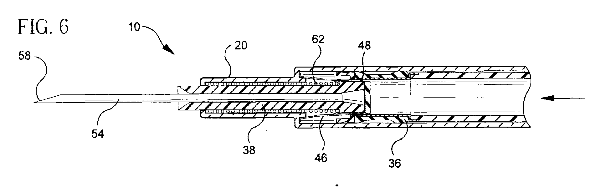
- a hypodermic syringe 10 of the invention includes an elongate barrel 14 having an open proximal end 16 and an open distal end 18 defining a receiver 20 with an inward shoulder 22.
- Barrel 14 has a hollow bore 24 therethrough extending from proximal end 16 to distal end 18.
- Proximal end 16 preferably includes a finger grip 17 to assist a user in gripping and using the syringe.
- Syringe 10 includes an elongate plunger 26 with a proximal end 28 and a distal open end 30.
- Plunger 26 has a cavity 32 therewithin extending proximally from distal end 30.
- Plunger 26 is disposed and sized to fit within bore 24 of barrel 14 for a slidable movement to define a chamber 34 for receiving and expelling fluids.
- Plunger 26 has a stopper 36 disposed at distal end 30 to occlude the open end of cavity 32. Stopper 36 is sized and shaped to form a slidably substantially fluid tight seal with bore 24 of the barrel for forming chamber 34.
- Syringe 10 of the invention has an elongate hub 38 with a proximal flange 40. Hub 38 is disposed within and sized for slidable movement within receiver 20 at distal end 18 of the barrel with flange 40 defining a distal end 42 of chamber 34 in the barrel. Hub 38 has a passageway 44 therethrough.
- a sleeve 46 sized to fit with a clearance about the hub, the sleeve being disposed about the hub between the shoulder 22 and flange 40 when hub 38 is disposed in receiver 20.
- Sleeve 46 has a sharpened proximal end to function as a cutting surface 48 disposed substantially against a distal surface 50 of the flange, sleeve 46 having at least one inward projection 52 located distally to cutting surface 48.
- Needle 54 has a pointed distal end 58 and a proximal end 60 connected to passageway 44 of the hub so that when hub 38 is disposed in receiver 20 at the distal end of the barrel, pointed end 58 of the needle extends distally outwardly and fluid path 56 of the needle is in fluid communication with chamber 34 of the barrel.
- Distal end 30 of plunger 26 preferably further includes an anvil 64, best seen in Fig. 11, and stopper 36 includes a proximal void 66.
- Anvil 64 is preferably disposed within void 66 in stopper 36 to engage cutting surface 48 of sleeve 46 when the cutting surface of the sleeve engages stopper 36, anvil 64 thereby facilitating the cut by cutting surface 48 by providing a shearing action with the cutting surface through stopper 36 to expose cavity 32 in plunger 26.
- Plunger 26 preferably includes a proximal finger press 27 located at the proximal end 28 to facilitate movement of the plunger.
- Fig. 4 illustrates the proximal movement of plunger 26 within barrel 14 to cause expansion of chamber 34 to draw fluid.
- Fig. 5 shows plunger 26 being moved distally to a position beyond that required to expel any fluid contained in chamber 34 causes cutting surface 48 to cut through flange 40. This distal movement also causes hub 34 to engage inward projection 52 on sleeve 46 to prevent distal movement of the hub, best seen in Fig.
- a preferred embodiment of sleeve 46 is shown in Fig. 9 and an alternate embodiment, sleeve 146 is shown in Fig. 9a.
- the sleeve is preferably formed from a metallic material, preferably stainless steel or the like, and formed into the desired shape by a deep drawing process. Following the forming, the sleeve is subjected to an electro-etching process that sharpens edge 48, 148 as well as cleaning and polishing the inside and the outside of the sleeve.
- Inward projection 52 either may be formed in the initial preferred deep draw process used for forming sleeve 46, or as a secondary operation.
- projection 152 is formed as one or more continuous inward ribs that serve to engage hub 38 during the cutting of stopper 36. Similar methods and materials are suitable for forming anvil 64.
- sleeve 46 and 146 include a foot portion 53 and 153 respectively to support the sleeve at the distal end of barrel 14.
- barrel 14 and receiver 20 form an interface 21 that serves to receive foot portion 53 or 153 when the sleeve is disposed in the barrel.
- an assembly including hub 38, spring 62 and sleeve 46 is put together by placing spring 62 over hub 38 to engage flange 40 and then sleeve 46 is placed over the spring to engage the distal side of flange 40.
- This assembly is then introduced, see Fig. 10, into open proximal end 16 of barrel 14 and moved distally through bore 24 to a position where a depression 66 engages an inward projection 68 on the inside surface of bore 24.
- flange 40 is positioned so that depression 66 engages inward projection 66, hub 38 is retained in barrel 14, spring 62 is in a compressed state between flange 40 and shoulder 22 and foot 53 is disposed at interface 21.
- a distal end 45 of hub 38 is then available to receive needle 54 using conventional cannulation apparatus.
- distal end 45 of the hub projects beyond shoulder 22 of the receiver.
- the needle cannulation process preferably includes application of a preselected amount of an adhesive adjacent to proximal end 60 of the needle and positioning the needle in passageway 44 of hub 38 so that sharpened end 58 projects distally outwardly and fluid path 56 of the needle is in fluid communication with chamber 34 of the barrel.
- the adhesive serves to bond needle 54 into hub 38.
- a lubricant may be applied to the needle using the same equipment used for conventional non-retractable fixed needle syringes.
- a shield 70 is placed over needle 54 to engage receiver 20. Shield 70 serves to protect sharpened point 58 from inadvertent exposure or damage during handling prior to its intended use.
- syringe 10 with shield 70 in a package 74, best seen in Fig. 2, formed from materials substantially resistant to the passage of microorganisms as a final package.
- barrel 14 may include a collar 76 at proximal end 16 of the barrel.
- a cap 78 may be placed on collar 76 to cover plunger 26 and occlude open proximal end 16 that, in conjunction with shield 70, to render syringe 10 "self-contained".
- a self-contained syringe is considered to be self packaged in that all components of the syringe that are considered "fluid-path" are substantially protected from outside contamination as long as cap 78 and shield 70 are intact.
- Cap 78 and shield 70 preferably include tortuous path venting to the atmosphere. The venting allows positioning and exercise of plunger 26 during assembly without displacement of shield 70.
- the syringe is exposed to conditions that substantially render any microorganism inside the package or within the fluid path of the syringe non-viable. Suitable conditions for rendering microorganisms non-viable include, but are not limited to exposure to ionizing radiation such as gamma, electron-beam and ultra-violet; chemical agents such as ethylene oxide, vapor phase hydrogen peroxide and the like. After sufficient exposure, syringe 10 is considered sterile until package 74 is opened or until shield 70 and cap 78 are removed.
- package 74 is constructed so that it provides tamper evidence of its being opened.
- cap 78 and shield 70 are affixed to syringe 10 with a frangible label, heat-stake or the like that provide the user with tamper evidence of any removal or disruption of the cap and shield.
- Suitable materials for forming barrel 14 include, but are not limited to, thermoplastic materials such as polypropylene, polyethylene, polycarbonate and the like. Polypropylene is preferred. Suitable materials for forming plunger 26 include thermoplastics such as filled polystyrene, polypropylene and the like. Filled polystyrene is preferred. Hub 38 may be formed from thermoplastic materials such as polypropylene, polystyrene, polyethylene and the like, with polypropylene being preferred. Cap 78 may be formed from thermoplastic materials such as polyethylene, polyproplyene, polycarbonate and the like, with polyethylene being preferred. Shield 70 may be formed from thermoplastic materials such as polyethylene, polypropylene and the like, with polyethylene being preferred.
- Stopper 36 may be formed from a thermoplastic material such as styrene block copolymer and the like. Alternatively, a thermoset material such as natural rubber or synthetic rubber may be used. Preferably, the material selected is somewhat resilient so that stopper 36 readily forms a fluid tight seal with the inside surface of bore 24 of the barrel.
- Spring 62 is preferably formed from a metallic material such as a stainless steel wire. By forming spring 62 from stainless steel wire, the gauge of the wire and the number of turns of the spring can be selected to provide spring 62 with sufficient bias when it is compressed between shoulder 22 and flange 40 to urge hub 38 into cavity 32 once flange 40 and stopper 36 are cut to expose the cavity.
- Syringe 10 of the invention offers several real benefits to the art of drug delivery.
- Syringe 10 has similar function and utility to conventional non-retractable syringes. Unlike many of the syringes previously disclosed, syringe 10 of the invention has little "dead-space", i.e., undeliverable volume contained in chamber 34 that would confound measurement of mixing insulins in the syringe, a common practice.
- Syringe 10 offers selective and reliable retraction of needle 54 to a position within the syringe that substantially prevents inadvertent exposure to sharpened point 58 of the needle.
- the components used to provide the selective needle retraction capability are substantially compatible with the equipment used in the manufacture of conventional non-retractable syringes.
- the components used to provide the retraction capability are readily produced in a small enough size to fit within the bore of a one cc syringe with a diameter of about one quarter inch. Additionally, the components used to provide the retraction capability are relatively simple and straightforward to assemble. Many of the previously disclosed retractable needle syringes are complex, difficult to manufacture and assemble. Additionally, the activation of these previously disclosed retraction mechanisms either is not compatible with much common usage of the syringes, i.e. mixing of insulins, or is dependent on balancing the forces required to expel the syringe contents against the force required to activate the retraction mechanism.
- Syringe 10 of the invention provides users of small capacity syringes with the benefit of selective retractability of the needle and provides the capability for efficient manufacture of the large numbers of syringes required by the market by being relatively simple to manufacture and assemble as well as the ability to utilize much of the equipment used to produce conventional syringes.
Abstract

Description
Claims (16)
- A hypodermic syringe with a selectively retractable needle comprising:an elongate barrel having an open proximal end and a distal end defining a receiver with an inward shoulder, said barrel having a hollow bore therethrough extending from said proximal end to said distal end;an elongate plunger having a proximal end and an open distal end, said plunger having a cavity therewithin extending proximally from said distal end, said plunger being disposed and sized to fit within said bore of said barrel for a slidable movement to define a chamber for receiving and expelling fluids, said plunger having a stopper disposed at said distal end to occlude said open end of said cavity, said stopper being sized and shaped to form a slidably substantially fluid tight seal with said bore of said barrel for forming said chamber;an elongate hub having a proximal flange, said hub disposed within and sized for slidable movement within said receiver at said distal end of said barrel with said flange defining a distal end of said chamber in said barrel, said hub having a passageway therethrough;a sleeve sized to fit with a clearance about said hub, said sleeve being disposed about said hub between said shoulder and said flange, said sleeve having a sharpened proximal end disposed substantially against a distal surface of said flange, said sleeve having at least one inward projection located distally to said cutting surface;an elongate needle having a fluid path therethrough, said needle having a pointed distal end and a proximal end connected tosaid passageway of said hub so that when said hub is disposed in said receiver in at said distal end of said barrel, said pointed end of said needle extends distally outwardly and said fluid path of said needle is in fluid communication with said chamber of said barrel;an elongate spring disposed about said hub sufficiently compressed to provide a bias between said receiver and said flange so that when a force greater than a force required to expel fluid from said chamber is applied to said plunger, said hub is moved distally in said receiver against said bias of said spring a sufficient distance to cause said cutting surface of said sleeve to engage and to cut through said flange and to engage said at least one inward projection on said sleeve against said hub to allow said cutting surface of said sleeve to cut through said stopper to expose said cavity in said plunger thereby to allow said bias of said spring to urge a sufficient movement of said hub into said cavity in said plunger to retract said needle to a position within said syringe where inadvertent contact with said pointed distal end is substantially prevented.
- The retractable needle syringe of Claim 1 wherein said distal end of said plunger further includes an anvil and said stopper includes a proximal void, said anvil being disposed within said void in said stopper to engage said cutting surface of said sleeve when said cutting surface of said sleeve engages said stopper, said anvil thereby facilitating the cut by said cutting surface through said stopper to expose said cavity in said plunger.
- The retractable needle syringe of Claim 2 wherein said anvil is formed from a metallic material.
- The retractable needle syringe of Claim 1 wherein said receiver is sized so that said open distal end of said barrel defining said receiver is sized and shaped to allow a slidable movement of said hub while retaining said spring about said hub.
- The retractable needle syringe of Claim 1 wherein said sleeve is formed into a tapered shape wherein said proximal end of said sleeve has a smaller diameter than a distal end of said sleeve, thereby facilitating a stretching of said stopper when said resilient stopper is cut by said cutting surface.
- The retractable needle syringe of Claim 5 wherein said sleeve is formed from a metallic material.
- The retractable needle syringe of Claim 6 wherein said sleeve is subjected to an electrochemical treatment thereby enhancing said cutting surface's sharpness properties.
- The retractable needle syringe of Claim 6 wherein said metallic material is stainless steel,
- The retractable needle syringe of Claim 1 wherein said proximal end of said barrel further comprises a finger flange for assisting a practitioner's grip of said syringe during a use.
- The retractable needle syringe of Claim 9 wherein said finger flange further includes a collar projecting proximally a sufficient distance, said collar being disposed and shaped to receive a removable cap for covering said plunger and wherein said receiver at said distal end of said barrel is shaped to receive a removable shield for protecting said sharp distal end of said needle.
- The retractable needle syringe of Claim 10 wherein said cap disposed on said collar and said shield disposed on said receiver is sufficiently to substantially prevent passage of any microorganisms beyond said cap and said shield, and wherein said syringe is exposed to conditions that substantially render any microorganisms therein non-viable.
- The retractable needle syringe of Claim 11 wherein said cap and said shield are each provided with a frangible attachment, whereby neither said cap nor said shield are removable from said collar and said receiver respectively without disruption of said attachments, thereby providing a positive evidence to the practitioner that once said cap and said shield are positioned on said collar and said receiver, they have not been removed prior to the intended use, thereby providing a "tamper-evidence".
- The retractable needle syringe of Claim 1 wherein said spring is formed from a metallic material.
- The retractable needle syringe of Claim 1 being placed in a package formed from materials substantially resistant to the passage of microorganisms and exposed to conditions that render any microorganisms therein substantially non-viable.
- The retractable needle syringe of Claim 1 wherein said bore of said barrel further comprises an inward projection and said flange on said hub includes a cooperating recess so that when said hub is positioned in said receiver, said depression in said flange engages said projection in said barrel thereby retaining said hub.
- A method for assembling a retractable needle syringe comprises:providing an elongate barrel having an open proximal end and an open distal end defining a receiver with an inward shoulder, said barrel having a hollow bore therethrough extending from said proximal end to said distal end;providing an elongate hub having with a proximal flange and a distal tip, said hub disposed within and sized for slidable movement within said receiver at said distal end of said barrel with said flange defining a distal end of said chamber in said barrel, said hub having a passageway therethrough;placing an elongate spring about said hub;placing a sleeve sized having a sharpened proximal end and sized to fit with a clearance about said hub over said spring with said sharpened proximal end being located distally to said flange and said hub thereby forming an assembly;inserting said assembly into said barrel from said proximal end of said barrel to a position wherein at least a portion of said distal tip of said hub projects distally from said receiver, so that said spring is compressed between said flange and said shoulder;providing an elongate needle having a fluid path therethrough, said needle having a pointed distal end and a proximal end;mounting said needle into said distal tip of said receiver so that said fluid path of said needle is connected to said passageway of said hub with said pointed end of said needle extending distally outwardly and said fluid path of said needle is in fluid communication with said chamber of said barrel;providing an elongate plunger with a proximal end and a distal open end, said plunger having a cavity therewithin extending proximally from said distal end, said plunger being sized to fit within said bore of said barrel for a slidable movement to define a chamber for receiving and expelling fluids, said plunger having a stopper disposed at said distal end to occlude said open end of said cavity, said stopper being sized and shaped to form a slidably substantially fluid tight seal with said bore of said barrel for forming said chamber; andplacing said distal end of said plunger into said proximal end of said barrel thereby assembling said syringe having said retractable needle.
Applications Claiming Priority (2)
| Application Number | Priority Date | Filing Date | Title |
|---|---|---|---|
| US604429 | 2000-06-27 | ||
| US09/604,429 US6599268B1 (en) | 2000-06-27 | 2000-06-27 | Hypodermic syringe with a selectively retractable needle |
Publications (2)
| Publication Number | Publication Date |
|---|---|
| EP1166810A1 true EP1166810A1 (en) | 2002-01-02 |
| EP1166810B1 EP1166810B1 (en) | 2004-09-01 |
Family
ID=24419566
Family Applications (1)
| Application Number | Title | Priority Date | Filing Date |
|---|---|---|---|
| EP01111648A Expired - Lifetime EP1166810B1 (en) | 2000-06-27 | 2001-05-14 | Hypodermic syringe with a selectively retractable needle |
Country Status (13)
| Country | Link |
|---|---|
| US (1) | US6599268B1 (en) |
| EP (1) | EP1166810B1 (en) |
| JP (1) | JP4903317B2 (en) |
| CN (1) | CN1216656C (en) |
| AT (1) | ATE274945T1 (en) |
| AU (1) | AU782186B2 (en) |
| BR (1) | BR0102520B1 (en) |
| CA (1) | CA2348810C (en) |
| DE (1) | DE60105233T2 (en) |
| DK (1) | DK1166810T3 (en) |
| ES (1) | ES2230201T3 (en) |
| MX (1) | MXPA01006619A (en) |
| NZ (1) | NZ512323A (en) |
Cited By (4)
| Publication number | Priority date | Publication date | Assignee | Title |
|---|---|---|---|---|
| EP1438979A1 (en) | 2002-12-19 | 2004-07-21 | Henrik Brocks | Disposable hypodermic syringe |
| WO2009016234A1 (en) * | 2007-08-01 | 2009-02-05 | Süddeutsche Feinmechanik GmbH | Cannula device having pivotable needle guard |
| WO2014014729A1 (en) * | 2012-07-16 | 2014-01-23 | Becton, Dickinson And Company | Packageless syringe assembly with sterilizable fluid path |
| GB2552798A (en) * | 2016-08-09 | 2018-02-14 | Danish Medical Innovatoin Aps | Medical device |
Families Citing this family (31)
| Publication number | Priority date | Publication date | Assignee | Title |
|---|---|---|---|---|
| US6432087B1 (en) * | 2000-07-31 | 2002-08-13 | Becton, Dickinson And Company | Hypodermic syringe with selectively retractable needle |
| US6966897B2 (en) * | 2000-09-22 | 2005-11-22 | Arte Corporation | Combined container-syringe and assembly method of the same |
| AUPR373001A0 (en) * | 2001-03-14 | 2001-04-12 | Glenord Pty Ltd | Improved non-reusable syringe |
| US6923936B2 (en) * | 2001-10-23 | 2005-08-02 | Medtronic Minimed, Inc. | Sterile device and method for producing same |
| IL157984A (en) | 2003-09-17 | 2015-02-26 | Dali Medical Devices Ltd | Autoneedle |
| IL157981A (en) | 2003-09-17 | 2014-01-30 | Elcam Medical Agricultural Cooperative Ass Ltd | Auto-injector |
| IL160891A0 (en) | 2004-03-16 | 2004-08-31 | Auto-mix needle | |
| ES2821653T3 (en) * | 2004-08-13 | 2021-04-27 | Becton Dickinson Co | Retractable Needle Syringe Assembly |
| CA2580092C (en) | 2004-09-03 | 2011-03-22 | John Klippenstein | Single-use pneumatic safety syringe with retractable needle |
| BRPI0516484A (en) * | 2004-10-14 | 2008-09-09 | Safety Medical International I | safety medical syringe with retractable needle |
| CN100394991C (en) * | 2004-10-25 | 2008-06-18 | 镱钛科技股份有限公司 | Retraction type safety syringe |
| DE102005062206B3 (en) * | 2005-12-24 | 2006-12-14 | Lts Lohmann Therapie-Systeme Ag | Disposable injection syringe has comprises piston and cylinder unit filled with active material and spring unit comprising coil spring held in compressed state by band which is cut before syringe is used by blade at its top |
| US7846135B2 (en) | 2006-02-24 | 2010-12-07 | Midland Medical Holding LLC | Retractable needle syringe with needle trap |
| US9592375B2 (en) | 2006-05-18 | 2017-03-14 | Hyprotek, Inc. | Intravascular line and port cleaning methods, methods of administering an agent intravascularly, methods of obtaining/testing blood, and devices for performing such methods |
| US7637889B2 (en) * | 2006-11-15 | 2009-12-29 | Glynntech, Inc. | Drug delivery device with sliding valve and methodology |
| US8382713B2 (en) * | 2006-12-11 | 2013-02-26 | Kenergy Scientific, Inc. | Drug delivery device and methodology |
| US20100201259A1 (en) * | 2007-07-31 | 2010-08-12 | Sumitomo Chemical Company, Limited | Compound and method for producing the same, and ink composition, thin film, organic transistor and organic electroluminescence device, each using the same |
| US8556854B2 (en) | 2010-07-22 | 2013-10-15 | Becton, Dickinson And Company | Dual chamber syringe with retractable needle |
| US8556855B2 (en) | 2010-07-22 | 2013-10-15 | Becton, Dickinson And Company | Dual chamber syringe with retractable needle |
| US8721599B2 (en) | 2010-07-22 | 2014-05-13 | Becton, Dickinson And Company | Dual chamber passive retraction needle syringe |
| US9550030B2 (en) | 2010-07-22 | 2017-01-24 | Becton, Dickinson And Company | Dual chamber syringe with retractable needle |
| US8512295B2 (en) | 2010-08-19 | 2013-08-20 | West Pharmaceutical Services, Inc. | Rigid needle shield |
| US9078975B2 (en) | 2011-09-30 | 2015-07-14 | Becton Dickinson France, S.A.S. | Syringe having pivoting arm plunger rod |
| SG10202002098XA (en) * | 2013-10-28 | 2020-04-29 | Becton Dickinson Co | Leak-free stopper for a syringe assembly having low breakloose and sustaining forces |
| CN106687080A (en) * | 2014-09-11 | 2017-05-17 | 普西维达公司 | Injector apparatus |
| CN205252220U (en) | 2014-10-31 | 2016-05-25 | L.O.M.实验室股份有限公司 | Retractable needle formula syringe |
| CA3012020A1 (en) | 2015-01-20 | 2016-07-28 | L.O.M. Laboratories Inc. | Retractable needle syringe with unitary propellant release module |
| USD765838S1 (en) | 2015-03-26 | 2016-09-06 | Tech Group Europe Limited | Syringe retention clip |
| AU2017360893A1 (en) * | 2016-11-17 | 2019-07-04 | Syrinjector Ltd. | Online, real-time mass vaccination and data collection system |
| JP7295859B2 (en) * | 2017-12-29 | 2023-06-21 | ベクトン・ディキンソン・アンド・カンパニー | Low-cost syringe with durable and disposable components |
| CN110375067A (en) * | 2019-06-25 | 2019-10-25 | 北京北分瑞利分析仪器(集团)有限责任公司 | A kind of piston sealing structure applied to syringe |
Citations (9)
| Publication number | Priority date | Publication date | Assignee | Title |
|---|---|---|---|---|
| US4838869A (en) | 1987-08-29 | 1989-06-13 | Allard Edward F | Retractable needle syringe |
| US4900307A (en) | 1987-04-29 | 1990-02-13 | Kulli John C | Safety retracting needle for use with syringe |
| US4994034A (en) | 1989-07-11 | 1991-02-19 | Botich Michael J | Retractable needle hypodermic syringe system |
| US5019044A (en) | 1989-08-14 | 1991-05-28 | Tsao Chien Hua | Safety hypodermic syringe |
| US5053010A (en) | 1990-10-03 | 1991-10-01 | Triad Technology | Safety syringe with retractable needle |
| US5180369A (en) | 1992-01-20 | 1993-01-19 | Dysarz Edward D | Self destructive safety syringe |
| US5180370A (en) | 1992-05-18 | 1993-01-19 | Gillespie Elgene R | Safety hypodermic syringe with retractable needle |
| US5188599A (en) | 1989-07-11 | 1993-02-23 | Med-Design, Inc. | Retractable needle system |
| US6036674A (en) * | 1998-12-18 | 2000-03-14 | Becton Dickinson And Company | Retracting needle syringe |
Family Cites Families (17)
| Publication number | Priority date | Publication date | Assignee | Title |
|---|---|---|---|---|
| US4534827A (en) * | 1983-08-26 | 1985-08-13 | Henderson Donald W | Cutting implement and method of making same |
| ES2009709A6 (en) | 1989-01-24 | 1989-10-01 | Villar Pascual Jose Antonio | Single-use safety syringe |
| GB9107647D0 (en) | 1991-04-11 | 1991-05-29 | Jeffrey Peter | Syringe construction providing needle point protection |
| EP0515766B1 (en) | 1991-05-29 | 1994-08-24 | Paolo Caselli | Security syringe with retractable hollow needle |
| US5752059A (en) | 1992-12-29 | 1998-05-12 | Apple Computer, Inc. | Apparatus and method for representing electronic mail |
| US5385551A (en) | 1993-09-22 | 1995-01-31 | Shaw; Thomas J. | Nonreusable medical device with front retraction |
| US5826062A (en) | 1996-05-30 | 1998-10-20 | International Business Machines Corporation | Method and apparatus for converting and displaying a multimedia document at a client |
| US5769822A (en) | 1996-09-13 | 1998-06-23 | Mcgary; R. Kern | Non-reusable retractable safety syringe |
| US5917489A (en) | 1997-01-31 | 1999-06-29 | Microsoft Corporation | System and method for creating, editing, and distributing rules for processing electronic messages |
| US6189026B1 (en) | 1997-06-16 | 2001-02-13 | Digital Equipment Corporation | Technique for dynamically generating an address book in a distributed electronic mail system |
| US6088696A (en) | 1997-09-29 | 2000-07-11 | Ericsson Inc. | Mailing/filing system for congruently categorizing different types of electronic mail resources received through a messaging system |
| US6205432B1 (en) | 1998-06-05 | 2001-03-20 | Creative Internet Concepts, Llc | Background advertising system |
| US6249807B1 (en) | 1998-11-17 | 2001-06-19 | Kana Communications, Inc. | Method and apparatus for performing enterprise email management |
| US6010486A (en) | 1998-12-18 | 2000-01-04 | Becton Dickinson And Company | Retracting needle syringe |
| US6368303B1 (en) * | 1999-10-15 | 2002-04-09 | Becton, Dickinson And Company | Retracting needle syringe |
| US6183440B1 (en) * | 2000-05-25 | 2001-02-06 | Becton, Dickinson And Company | Hypodermic syringe having a selectively retractable needle |
| US6432087B1 (en) * | 2000-07-31 | 2002-08-13 | Becton, Dickinson And Company | Hypodermic syringe with selectively retractable needle |
-
2000
- 2000-06-27 US US09/604,429 patent/US6599268B1/en not_active Expired - Lifetime
-
2001
- 2001-05-14 EP EP01111648A patent/EP1166810B1/en not_active Expired - Lifetime
- 2001-05-14 AT AT01111648T patent/ATE274945T1/en not_active IP Right Cessation
- 2001-05-14 DE DE60105233T patent/DE60105233T2/en not_active Expired - Lifetime
- 2001-05-14 DK DK01111648T patent/DK1166810T3/en active
- 2001-05-14 ES ES01111648T patent/ES2230201T3/en not_active Expired - Lifetime
- 2001-05-25 CA CA002348810A patent/CA2348810C/en not_active Expired - Lifetime
- 2001-06-13 NZ NZ512323A patent/NZ512323A/en not_active IP Right Cessation
- 2001-06-20 AU AU53949/01A patent/AU782186B2/en not_active Expired
- 2001-06-21 BR BRPI0102520-1A patent/BR0102520B1/en not_active IP Right Cessation
- 2001-06-27 CN CN01122523.8A patent/CN1216656C/en not_active Expired - Lifetime
- 2001-06-27 JP JP2001195210A patent/JP4903317B2/en not_active Expired - Lifetime
- 2001-06-27 MX MXPA01006619A patent/MXPA01006619A/en active IP Right Grant
Patent Citations (9)
| Publication number | Priority date | Publication date | Assignee | Title |
|---|---|---|---|---|
| US4900307A (en) | 1987-04-29 | 1990-02-13 | Kulli John C | Safety retracting needle for use with syringe |
| US4838869A (en) | 1987-08-29 | 1989-06-13 | Allard Edward F | Retractable needle syringe |
| US4994034A (en) | 1989-07-11 | 1991-02-19 | Botich Michael J | Retractable needle hypodermic syringe system |
| US5188599A (en) | 1989-07-11 | 1993-02-23 | Med-Design, Inc. | Retractable needle system |
| US5019044A (en) | 1989-08-14 | 1991-05-28 | Tsao Chien Hua | Safety hypodermic syringe |
| US5053010A (en) | 1990-10-03 | 1991-10-01 | Triad Technology | Safety syringe with retractable needle |
| US5180369A (en) | 1992-01-20 | 1993-01-19 | Dysarz Edward D | Self destructive safety syringe |
| US5180370A (en) | 1992-05-18 | 1993-01-19 | Gillespie Elgene R | Safety hypodermic syringe with retractable needle |
| US6036674A (en) * | 1998-12-18 | 2000-03-14 | Becton Dickinson And Company | Retracting needle syringe |
Cited By (9)
| Publication number | Priority date | Publication date | Assignee | Title |
|---|---|---|---|---|
| EP1438979A1 (en) | 2002-12-19 | 2004-07-21 | Henrik Brocks | Disposable hypodermic syringe |
| WO2009016234A1 (en) * | 2007-08-01 | 2009-02-05 | Süddeutsche Feinmechanik GmbH | Cannula device having pivotable needle guard |
| WO2014014729A1 (en) * | 2012-07-16 | 2014-01-23 | Becton, Dickinson And Company | Packageless syringe assembly with sterilizable fluid path |
| EP3216469A1 (en) * | 2012-07-16 | 2017-09-13 | Becton, Dickinson and Company | Packageless syringe assembly with sterilizable fluid path |
| US10064990B2 (en) | 2012-07-16 | 2018-09-04 | Becton, Dickinson And Company | Packageless syringe assembly with sterilizable fluid path |
| US11529455B2 (en) | 2012-07-16 | 2022-12-20 | Becton, Dickinson And Company | Packageless syringe assembly with sterilizable fluid path |
| US11883625B2 (en) | 2012-07-16 | 2024-01-30 | Becton, Dickinson And Company | Packageless syringe assembly with sterilizable fluid path |
| GB2552798A (en) * | 2016-08-09 | 2018-02-14 | Danish Medical Innovatoin Aps | Medical device |
| GB2552798B (en) * | 2016-08-09 | 2018-08-22 | Danish Medical Innovation Aps | Medical device |
Also Published As
| Publication number | Publication date |
|---|---|
| AU5394901A (en) | 2002-01-03 |
| BR0102520B1 (en) | 2010-05-04 |
| MXPA01006619A (en) | 2002-03-20 |
| DK1166810T3 (en) | 2004-11-01 |
| EP1166810B1 (en) | 2004-09-01 |
| DE60105233T2 (en) | 2005-09-08 |
| CA2348810A1 (en) | 2001-12-27 |
| AU782186B2 (en) | 2005-07-07 |
| JP2002085562A (en) | 2002-03-26 |
| CA2348810C (en) | 2009-09-08 |
| BR0102520A (en) | 2002-02-05 |
| ES2230201T3 (en) | 2005-05-01 |
| JP4903317B2 (en) | 2012-03-28 |
| ATE274945T1 (en) | 2004-09-15 |
| US6599268B1 (en) | 2003-07-29 |
| CN1216656C (en) | 2005-08-31 |
| DE60105233D1 (en) | 2004-10-07 |
| NZ512323A (en) | 2003-03-28 |
| CN1374135A (en) | 2002-10-16 |
Similar Documents
| Publication | Publication Date | Title |
|---|---|---|
| EP1166810B1 (en) | Hypodermic syringe with a selectively retractable needle | |
| US6432087B1 (en) | Hypodermic syringe with selectively retractable needle | |
| US6409701B1 (en) | Hypodermic syringe with selectively retractable needle | |
| EP1166809B1 (en) | Hypodermic syringe with selectively retractable needle | |
| US6413237B1 (en) | Hypodermic syringe with selectively retractable needle | |
| EP1184049B1 (en) | Hypodermic syringe with selectively retractable needle | |
| US6689106B2 (en) | Retracting needle assembly for a syringe | |
| AU2009202739A1 (en) | Hypodermic syringe with selectively retractable needle |
Legal Events
| Date | Code | Title | Description |
|---|---|---|---|
| PUAI | Public reference made under article 153(3) epc to a published international application that has entered the european phase |
Free format text: ORIGINAL CODE: 0009012 |
|
| AK | Designated contracting states |
Kind code of ref document: A1 Designated state(s): AT BE CH CY DE DK ES FI FR GB GR IE IT LI LU MC NL PT SE TR |
|
| AX | Request for extension of the european patent |
Free format text: AL;LT;LV;MK;RO;SI |
|
| 17P | Request for examination filed |
Effective date: 20020702 |
|
| AKX | Designation fees paid |
Free format text: AT BE CH CY DE DK ES FI FR GB GR IE IT LI LU MC NL PT SE TR |
|
| GRAP | Despatch of communication of intention to grant a patent |
Free format text: ORIGINAL CODE: EPIDOSNIGR1 |
|
| GRAS | Grant fee paid |
Free format text: ORIGINAL CODE: EPIDOSNIGR3 |
|
| GRAA | (expected) grant |
Free format text: ORIGINAL CODE: 0009210 |
|
| AK | Designated contracting states |
Kind code of ref document: B1 Designated state(s): AT BE CH CY DE DK ES FI FR GB GR IE IT LI LU MC NL PT SE TR |
|
| PG25 | Lapsed in a contracting state [announced via postgrant information from national office to epo] |
Ref country code: AT Free format text: LAPSE BECAUSE OF FAILURE TO SUBMIT A TRANSLATION OF THE DESCRIPTION OR TO PAY THE FEE WITHIN THE PRESCRIBED TIME-LIMIT Effective date: 20040901 Ref country code: TR Free format text: LAPSE BECAUSE OF FAILURE TO SUBMIT A TRANSLATION OF THE DESCRIPTION OR TO PAY THE FEE WITHIN THE PRESCRIBED TIME-LIMIT Effective date: 20040901 Ref country code: NL Free format text: LAPSE BECAUSE OF FAILURE TO SUBMIT A TRANSLATION OF THE DESCRIPTION OR TO PAY THE FEE WITHIN THE PRESCRIBED TIME-LIMIT Effective date: 20040901 Ref country code: FI Free format text: LAPSE BECAUSE OF FAILURE TO SUBMIT A TRANSLATION OF THE DESCRIPTION OR TO PAY THE FEE WITHIN THE PRESCRIBED TIME-LIMIT Effective date: 20040901 Ref country code: LI Free format text: LAPSE BECAUSE OF FAILURE TO SUBMIT A TRANSLATION OF THE DESCRIPTION OR TO PAY THE FEE WITHIN THE PRESCRIBED TIME-LIMIT Effective date: 20040901 Ref country code: CH Free format text: LAPSE BECAUSE OF FAILURE TO SUBMIT A TRANSLATION OF THE DESCRIPTION OR TO PAY THE FEE WITHIN THE PRESCRIBED TIME-LIMIT Effective date: 20040901 |
|
| REG | Reference to a national code |
Ref country code: GB Ref legal event code: FG4D |
|
| REG | Reference to a national code |
Ref country code: CH Ref legal event code: EP |
|
| REG | Reference to a national code |
Ref country code: IE Ref legal event code: FG4D |
|
| REF | Corresponds to: |
Ref document number: 60105233 Country of ref document: DE Date of ref document: 20041007 Kind code of ref document: P |
|
| REG | Reference to a national code |
Ref country code: DK Ref legal event code: T3 |
|
| PG25 | Lapsed in a contracting state [announced via postgrant information from national office to epo] |
Ref country code: SE Free format text: LAPSE BECAUSE OF FAILURE TO SUBMIT A TRANSLATION OF THE DESCRIPTION OR TO PAY THE FEE WITHIN THE PRESCRIBED TIME-LIMIT Effective date: 20041201 Ref country code: GR Free format text: LAPSE BECAUSE OF FAILURE TO SUBMIT A TRANSLATION OF THE DESCRIPTION OR TO PAY THE FEE WITHIN THE PRESCRIBED TIME-LIMIT Effective date: 20041201 |
|
| NLV1 | Nl: lapsed or annulled due to failure to fulfill the requirements of art. 29p and 29m of the patents act | ||
| REG | Reference to a national code |
Ref country code: CH Ref legal event code: PL |
|
| REG | Reference to a national code |
Ref country code: ES Ref legal event code: FG2A Ref document number: 2230201 Country of ref document: ES Kind code of ref document: T3 |
|
| PG25 | Lapsed in a contracting state [announced via postgrant information from national office to epo] |
Ref country code: CY Free format text: LAPSE BECAUSE OF FAILURE TO SUBMIT A TRANSLATION OF THE DESCRIPTION OR TO PAY THE FEE WITHIN THE PRESCRIBED TIME-LIMIT Effective date: 20050514 Ref country code: LU Free format text: LAPSE BECAUSE OF NON-PAYMENT OF DUE FEES Effective date: 20050514 |
|
| PG25 | Lapsed in a contracting state [announced via postgrant information from national office to epo] |
Ref country code: MC Free format text: LAPSE BECAUSE OF NON-PAYMENT OF DUE FEES Effective date: 20050531 |
|
| ET | Fr: translation filed | ||
| PLBE | No opposition filed within time limit |
Free format text: ORIGINAL CODE: 0009261 |
|
| STAA | Information on the status of an ep patent application or granted ep patent |
Free format text: STATUS: NO OPPOSITION FILED WITHIN TIME LIMIT |
|
| 26N | No opposition filed |
Effective date: 20050602 |
|
| PG25 | Lapsed in a contracting state [announced via postgrant information from national office to epo] |
Ref country code: PT Free format text: LAPSE BECAUSE OF NON-PAYMENT OF DUE FEES Effective date: 20050201 |
|
| REG | Reference to a national code |
Ref country code: FR Ref legal event code: PLFP Year of fee payment: 16 |
|
| REG | Reference to a national code |
Ref country code: FR Ref legal event code: PLFP Year of fee payment: 17 |
|
| REG | Reference to a national code |
Ref country code: FR Ref legal event code: PLFP Year of fee payment: 18 |
|
| PGFP | Annual fee paid to national office [announced via postgrant information from national office to epo] |
Ref country code: ES Payment date: 20200602 Year of fee payment: 20 Ref country code: DE Payment date: 20200421 Year of fee payment: 20 Ref country code: FR Payment date: 20200422 Year of fee payment: 20 Ref country code: DK Payment date: 20200424 Year of fee payment: 20 Ref country code: IE Payment date: 20200422 Year of fee payment: 20 |
|
| PGFP | Annual fee paid to national office [announced via postgrant information from national office to epo] |
Ref country code: BE Payment date: 20200423 Year of fee payment: 20 Ref country code: GB Payment date: 20200423 Year of fee payment: 20 Ref country code: IT Payment date: 20200421 Year of fee payment: 20 |
|
| REG | Reference to a national code |
Ref country code: DE Ref legal event code: R071 Ref document number: 60105233 Country of ref document: DE |
|
| REG | Reference to a national code |
Ref country code: DK Ref legal event code: EUP Expiry date: 20210514 |
|
| REG | Reference to a national code |
Ref country code: GB Ref legal event code: PE20 Expiry date: 20210513 |
|
| REG | Reference to a national code |
Ref country code: IE Ref legal event code: MK9A |
|
| REG | Reference to a national code |
Ref country code: BE Ref legal event code: MK Effective date: 20210514 |
|
| PG25 | Lapsed in a contracting state [announced via postgrant information from national office to epo] |
Ref country code: GB Free format text: LAPSE BECAUSE OF EXPIRATION OF PROTECTION Effective date: 20210513 Ref country code: IE Free format text: LAPSE BECAUSE OF EXPIRATION OF PROTECTION Effective date: 20210514 |
|
| REG | Reference to a national code |
Ref country code: ES Ref legal event code: FD2A Effective date: 20220103 |
|
| PG25 | Lapsed in a contracting state [announced via postgrant information from national office to epo] |
Ref country code: ES Free format text: LAPSE BECAUSE OF EXPIRATION OF PROTECTION Effective date: 20210515 |