EP1164386A2 - Method and apparatus for a color scannerless range imaging system - Google Patents
Method and apparatus for a color scannerless range imaging system Download PDFInfo
- Publication number
- EP1164386A2 EP1164386A2 EP01201637A EP01201637A EP1164386A2 EP 1164386 A2 EP1164386 A2 EP 1164386A2 EP 01201637 A EP01201637 A EP 01201637A EP 01201637 A EP01201637 A EP 01201637A EP 1164386 A2 EP1164386 A2 EP 1164386A2
- Authority
- EP
- European Patent Office
- Prior art keywords
- image
- imaging system
- range
- optical path
- color
- Prior art date
- Legal status (The legal status is an assumption and is not a legal conclusion. Google has not performed a legal analysis and makes no representation as to the accuracy of the status listed.)
- Withdrawn
Links
Images


Classifications
-
- H—ELECTRICITY
- H04—ELECTRIC COMMUNICATION TECHNIQUE
- H04N—PICTORIAL COMMUNICATION, e.g. TELEVISION
- H04N5/00—Details of television systems
- H04N5/222—Studio circuitry; Studio devices; Studio equipment
- H04N5/2224—Studio circuitry; Studio devices; Studio equipment related to virtual studio applications
- H04N5/2226—Determination of depth image, e.g. for foreground/background separation
-
- G—PHYSICS
- G01—MEASURING; TESTING
- G01S—RADIO DIRECTION-FINDING; RADIO NAVIGATION; DETERMINING DISTANCE OR VELOCITY BY USE OF RADIO WAVES; LOCATING OR PRESENCE-DETECTING BY USE OF THE REFLECTION OR RERADIATION OF RADIO WAVES; ANALOGOUS ARRANGEMENTS USING OTHER WAVES
- G01S17/00—Systems using the reflection or reradiation of electromagnetic waves other than radio waves, e.g. lidar systems
- G01S17/88—Lidar systems specially adapted for specific applications
- G01S17/89—Lidar systems specially adapted for specific applications for mapping or imaging
-
- H—ELECTRICITY
- H04—ELECTRIC COMMUNICATION TECHNIQUE
- H04N—PICTORIAL COMMUNICATION, e.g. TELEVISION
- H04N13/00—Stereoscopic video systems; Multi-view video systems; Details thereof
- H04N13/20—Image signal generators
- H04N13/204—Image signal generators using stereoscopic image cameras
- H04N13/254—Image signal generators using stereoscopic image cameras in combination with electromagnetic radiation sources for illuminating objects
-
- G—PHYSICS
- G01—MEASURING; TESTING
- G01S—RADIO DIRECTION-FINDING; RADIO NAVIGATION; DETERMINING DISTANCE OR VELOCITY BY USE OF RADIO WAVES; LOCATING OR PRESENCE-DETECTING BY USE OF THE REFLECTION OR RERADIATION OF RADIO WAVES; ANALOGOUS ARRANGEMENTS USING OTHER WAVES
- G01S17/00—Systems using the reflection or reradiation of electromagnetic waves other than radio waves, e.g. lidar systems
- G01S17/02—Systems using the reflection of electromagnetic waves other than radio waves
- G01S17/06—Systems determining position data of a target
- G01S17/08—Systems determining position data of a target for measuring distance only
- G01S17/32—Systems determining position data of a target for measuring distance only using transmission of continuous waves, whether amplitude-, frequency-, or phase-modulated, or unmodulated
- G01S17/36—Systems determining position data of a target for measuring distance only using transmission of continuous waves, whether amplitude-, frequency-, or phase-modulated, or unmodulated with phase comparison between the received signal and the contemporaneously transmitted signal
Definitions
- the present invention is in the field of three-dimensional image capture and in particular to the capture of three-dimensional image information with a scannerless range imaging system.
- Standard image capture systems will capture images, such as photographic images, that are two-dimensional representations of the three-dimensional world.
- projective geometry best models the process of transforming the three-dimensional real world into the two-dimensional images.
- much of the information that is lost in the transformation is in the distance between the camera and image points in the real world.
- Methods and processes have been proposed to retrieve or record this information.
- Some methods such as one based on a scanner from Cyberware, Inc., use a laser to scan across a scene. Variations in the reflected light are used to estimate the range to the object.
- these methods require the subject to be close (e.g., within 2 meters) to the camera and are typically slow.
- Stereo imaging is a common example of another process, which is fast on capture but requires solving the "correspondence problem", that is, the problem of finding corresponding points in the two images. This can be difficult and limit the number of pixels having range data, due to a limited number of feature points that are suitable for the correspondence processing.
- the gain of an image intensifier within the receiver is modulated at the same frequency as the transmitter, so the amount of light reaching the sensor (a charge-coupled device) is a function of the range-dependent phase difference.
- a second image is then taken without receiver or transmitter modulation and is used to eliminate non-range-carrying intensity information. Both captured images are registered spatially, and a digital processor is used to operate on these two frames to extract range. Consequently, the range associated with each pixel is essentially measured simultaneously across the whole scene.
- the preferred method of estimating the range in the '616 patent uses a pair of captured images to be captured, one image with a destructive interference caused by modulating the image intensifier, and the other with the image intensifier set at a constant voltage.
- a more stable estimation method uses a series of at least three images, each with modulation applied to the image intensifier as described in commonly assigned copending application Serial No. 09/342,370, entitled “Method and Apparatus for Scannerless Range Image Capture Using Photographic Film” and filed June 29, 1999 in the names of Lawrence Allen Ray and Timothy P. Mathers..
- the distinguishing feature of each image is that the phase of the image intensifier modulation is unique relative to modulation of the illuminator.
- the preferred arrangement is for successive images to have a phase shift of 2 ⁇ / n radians (where n is the number of images) from the phase of the previous image.
- n is the number of images
- the resultant set of images is referred to as an image bundle.
- the range at a pixel location is estimated by selecting the intensity of the pixel at that location in each image of the bundle and performing a best fit of a sine wave of one period through the points.
- the phase of the resulting best-fitted sine wave is then used to estimate the range to the object based upon the wave-length of the illumination frequency.
- a drawback of methods using an image intensifier is that color information is lost.
- an image intensifier operates by converting photonic energy into a stream of electrons, amplifying the energy of the electrons and then converting the electrons back into photonic energy via a phosphor plate.
- One consequence of this process is that color information is lost. Since color is a useful property of images for many applications, a means of acquiring the color information that is registered along with the range information is extremely desirable.
- One approach to acquiring color is to place a dichromatic mirror in the optical path before the micro-channel-plate. Following the mirror a separate image capture plane (i.e., a separate image sensor) is provided for the range portion of the camera and another image capture plane (another sensor) is provided for the color texture capture portion of the camera. This is the approach taken by 3DV Technology with their Z-Cam product. Besides the added expense of two image capture devices, there are additional drawbacks in the need to register the two image planes precisely, together with alignment of the optical paths. Another difficulty is collating image pairs gathered by different sources.
- a scannerless range imaging camera may operate either as a digital camera or a camera utilizing film.
- a film based system there are some other requirements that need to be met. These requirements and means for satisfying them are described in the aforementioned copending application Serial No. 09/342,370.
- the drawback of such a camera system, including a film-based system is its inability to capture a color image.
- a color scannerless range imaging system includes an illumination for controllably illuminating a scene with modulated illumination and an image responsive element for capturing image light from the scene, including the modulated image light.
- the system establishes a primary optical path for directing image light toward the image responsive element.
- a beamsplitter located in the primary optical path separates the image light into two channels, a first channel including an infrared component and a second channel including a color texture component, whereby one of the channels traverses a secondary optical path distinct from the primary path.
- a modulating element is operative in the first channel to receive the infrared component and a modulating signal, and to generate a processed infrared component with phase data indicative of range information.
- An optical network is provided in the secondary optical path for recombining the secondary optical path into the primary optical path such that the processed infrared component and the color texture component are directed to the image responsive element.
- the current invention eliminates the requirement for two image capture planes, but allows the operator to collect a full range map with texture with a single exposure activation.
- the invention employs a dichromatic mirror to separate a channel for capturing range data and a channel for capturing color texture data, while only using a single image capture subsystem.
- the advantage of the present invention is that is provides a means of obtaining a color image along with range information for each point on the image.
- the invention includes a single optical assembly and a dual illuminating system so that both range and color information may be efficiently captured under the best illuminating conditions for each capture. The ability to accomplish this is provided in part by having the range capture system embodied as a camera attachment that is optically coupled with the image capture device.
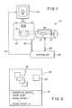
- FIG. 1 shows the main components of a color scannerless range imaging system in accordance with the invention.
- FIG. 2 is a diagram illustrating an image bundle and related data captured by the system shown in Figure 1.
- FIG. 3 is a diagram showing more detail of an image capture device as generally shown in Figure 1.
- FIG. 4 is a diagram showing more detail of the illumination system shown in Figure 1.
- FIG. 5 is a diagram showing more detail of the optical assembly shown in Figure 1.
- FIG. 6 is a diagram showing more detail of the controller shown in Figure 1.
- FIG. 7 is a diagram of the steps involved in processing image and range information in accordance with the invention.
- FIG. 8 is a block diagram of a range imaging system which can be used to capture a bundle of images.
- FIG. 9 is a perspective diagram of a computer system for implementing certain programs associated with the present invention.
- range imaging devices employing laser illuminators and capture devices including image intensifiers and electronic sensors are well known, the present description will be directed in particular to elements forming part of, or cooperating more directly with, apparatus in accordance with the present invention. Elements not specifically shown or described herein may be selected from those known in the art. Certain aspects of the embodiments to be described may be provided in software. Given the system as shown and described according to the invention in the following materials, software not specifically shown, described or suggested herein that is useful for implementation of the invention is conventional and within the ordinary skill in such arts.
- a range imaging system 10 is shown as a laser radar that is used to illuminate a scene 12 and then to capture an image bundle comprising a minimum of three images of the scene 12.
- An illuminator 14 emits a beam of electromagnetic radiation whose frequency is controlled by a modulator 16.
- the illuminator 14 is a laser device which includes an optical diffuser in order to effect a wide-field illumination.
- the modulating laser is an IR source. This is for eye-safety issues and to operate in the spectral region of maximal response by the capture system.
- the modulator 16 provides an amplitude varying sinusoidal modulation.
- the modulation frequency is sufficiently high (e.g., 10 MHz) to attain sufficiently accurate range estimates.
- the output beam 18 is directly toward the scene 12 and a reflected beam 20 is directly back toward a receiving section 22.
- the reflected beam 20 is a delayed version of the transmitted output beam 18, with the amount of phase delay being a function of the distance of the scene 12 from the range imaging system.
- the reflected beam 20 strikes the photocathode 24 within the image intensifier 26 producing a modulated electron stream proportional to the input amplitude variations. Since the photocathode 24 does not separately process the colors in the scene, the electron stream created at this point is essentially monochromatic, i.e., the color information is lost at this time.
- the purpose of the image intensifier is not only to intensify the image, but also to act as a modulating shutter. Accordingly, the image intensifier 26 is connected to the modulator 16, such that the electron stream strikes the intensifier 26 and is modulated by a modulating signal from the modulator 16. The modulated electron stream is then amplified through secondary emission by a microchannel plate 30. The intensified electron stream bombards a phosphor screen 32, which converts the energy into a visible light image.
- the intensified light image signal is captured by a capture mechanism 34, such as a charge-coupled device (CCD).
- the captured image signal is applied to a range processor 36 to determine the phase delay at each point in the scene.
- the pixel response P at this point is an integration of the reflected light and the effect of the intensification:
- the improved approach collects at least three phase images (referred to as an image bundle).
- the intensifier 26 and the laser illuminator 14 were phase locked.
- the improved approach shifts the phase of the intensifier 26 relative to the phase of the illuminator 14, and each of the phase images has a distinct phase offset.
- the range processor 36 is suitably connected to control the phase offset of the modulator 16, as well as the average illumination level and such other capture functions as may be necessary.
- phase term ⁇ is not directly accessible from a single image.
- equation (6) there are three unknown values and the form of the equation is quite simple.
- an image bundle shall be understood to constitute a collection of images which are of the same scene, but with each image having a distinct phase offset obtained from the modulation applied to the intensifier 26.
- an analogous analysis can be performed by phase shifting the illuminator 14 instead of the intensifier 26. If an image bundle comprising more than three images is captured, then the estimates of range can be enhanced by a least squares analysis using a singular value decomposition (see, e.g., W.H. Press, B.P. Flannery, S.A. Teukolsky and W.T. Vetterling, Numerical Recipes (the Art of Scientific Computing), Cambridge University Press, Cambridge, 1986).
- the first component is a an image capture device 40 for capturing an image.
- This may be, for example, a camera body where an image capture element 42 might be either a photosensitive film or an electronic sensor, such as a charged-coupled-device.
- This device 40 is able to capture a plurality of images.
- a remote trigger line 82 is provided for signaling the image capture device 40.
- a means for advancing, or driving, the image capture device 40 to prepare for a successive image capture must be available. Such capabilities are well known in relation to such image capture devices, and will not be described in detail.
- the second component is an illumination system 50 for producing high-frequency amplitude modulated illumination of a desired average amplitude, amplitude modulus and frequency. It is also desirable that the illumination system 50 further includes the capability of shifting the phase of the amplitude modulation between a set of prescribed phase offsets (alternatively, this function may be performed by modulation of the reflected illumination in the capture portion of the color scannerless range imaging system). It is also useful for the illumination system 50 to have a preferred operating wavelength.
- the third component is an optical assembly 60 comprised of a beam separator 62 for separating the incoming light into two channels, a first channel including an infrared component and a second channel including a color texture component, whereby one of the channels traverses a secondary optical path distinct from the primary path.
- the optical assembly 60 also includes a modulating element 64 opeat5ive in the first optical channel and an optical subassembly 66 for establishing the secondary optical path that bypasses the modulating element 64 and then rejoins the first optical channel.
- the first optical channel with the range information is directed straight through the optical assembly toward the image capture element 42 and the second optical channel with the color information bypasses the modulating element 62 via the optical subassembly 66 and then rejoins the first optical channel.
- the second optical channel could be directly toward the image capture element 42 and the first optical channel with the modulating element 62 would then bypass the second channel via the optical subassembly 66 and then rejoin second optical channel.
- the optical assembly is shown in Figure 1 removed from a threaded lens mount on the image capture device 40; this is to emphasize that the image capture device 40 may be based on a conventional camera body that could otherwise be fitted with a standard family of lenses for conventional photography.
- the fourth component is a controller 80, which manages the overall image capture process of the image and range capture system, including the operation of the illumination system 50, the image capture device 40, and the optical assembly 60.
- the controller 80 may include the remote trigger line 82 for causing the image capture device 40 to initiate an image capture sequence, and an illumination control line 84 for causing the illumination system 50 to emit the correct illumination at the correct moment. It is preferred, but not mandatory, that the controller 80 automatically operates the component 60, via an optics control line 86, to engage the appropriate optical channel as needed for operation according to the invention.
- the notion of an image bundle 90 is central to the range estimation method.
- the image bundle 90 includes a combination of images captured by the system as well as information pertinent to the individual images and information common to all the images.
- the image bundle contains two types of images: range images 92 related to the image capture portion of the process and a color image 94, commonly referred to as the texture image.
- Common information 96 in the image bundle 90 would typically include the number of images in the bundle (three or more) and the modulation frequency utilized by the camera system. Other information might be the number of horizontal and vertical pixels in the images, and/or data related to camera status at the time of the image capture.
- Image specific information will include the phase offset 1...N used for each (1...N) of the individual range images 92.
- the image bundle 90 includes a minimum of three such images, each of which are monochrome.
- Each of the range images 92 records the effect of a distinct phase offset applied to either the illumination system 50 or to elements of the optical assembly 60.
- the additional color image 94 is an image using the optical channel that does not contain range capture components. Although this is a color image, it is preferably, but not necessarily, the same size as the range images 92.
- the image capture device 40 shown in Figure 3 shares many aspects of a standard camera body--except that, in this embodiment, image capture is initiated from the controller 80. (It should also be apparent that the controller 80 could be part of, or attached to, the camera body, and the electrical linkages 82 and 86 could be made directly through the camera body, e.g., the linkage 86 could be made by contracts in the lens mount of the camera body to the optical assembly 60).
- the image capture element 42 is enabled to capture color images.
- the capture element 42 e.g., a charge-coupled device
- a color-filter-array (not shown) for generating a color image
- a color film is used and a method of introducing fiducial markings on the film is preferred for registration. Further details of a film capture system are shown in copending Serial No. 09/342,370.
- the image capture system requires image storage means to store all range images 92 in the image bundle 50, as well as a color texture image 94 in addition to the range images 92.
- an on-camera storage means such as a photosensitive film 44 with multiple frames or a digital storage mechanism 46, such as an internal memory together output connections to, e.g., a PCMCIA card or a floppy disk (not shown) for receiving images from the internal memory.
- a camera controller 48 connected to the remote trigger line 82 accepts trigger signals and causes the image capture device 40 to capture an image. Once an image is recorded the image capture device 40 must automatically prepare for an additional image capture.
- an automatic film advance (not shown) is activated by the camera controller 48.
- the camera controller 48 stores the image bundle data onto the digital storage mechanism 46 and clears internal buffers (not shown) for a subsequent image capture.
- the illumination system 50 shown in Figure 4 has the primary purpose of producing an amplitude-modulated illumination with its phase controllable for generating a shift in the transmitted wave pattern for each range image in the image bundle (although, as mentioned before, this function may be performed by modulation of the reflected illumination in the capture portion of the color scannerless range imaging system).
- the illumination system 50 includes a light source, which is preferably a laser light source 52 with an intensity of about 0.5 watt, and a modulation circuit 54 controllable through line 84 from the controller 80, for generating the requisite modulation signals of predetermined frequency with set of predetermined phase offsets.
- the preferred wavelength of the laser light is about 830 nm, as this wavelength provides an optimal balance between concerns for eye-safety and for the typical response of the optical assembly 60 described below.
- a diffusion lens 56 is positioned in front of the laser light source 52 in order to spread the modulated light across the desired field of view as uniformly as possible.
- the illumination system 50 also includes a standard wide-band illumination system 58 that is not modulated. This illumination source is used for normal photographic images.
- This device 58 may be a commonly known and understood flash of a standard camera system, e.g., a commonly available electronic flash of the type useful with photographic cameras.
- the illumination system 50 is connected via the control line 84 to the controller 80, which directs the illumination system 50 to operate in either of the following modes: a) a first mode in which the laser is operated to illuminate the scene with a plurality (bundle) of exposures, each with a unique phase offset applied to its modulated frequency; and b) a second mode in which the standard wide-band illumination system 58 is turned on and the flash is initiated by the controller during capture of the color texture image.
- the illumination system 50 may be unnecessary for the illumination system 50 to operate in the second mode in order to capture a color image; in that case, the image capture device would be instructed to operate without flash. Moreover, the sequence of image capture may be reversed, that is, the second mode may be engaged before the first mode or, indeed, the second mode might in specific situations be engaged between the several exposures of the first mode.
- the illumination system 50 also communicates with the controller 40 via the line 84 to indicate that all systems are ready for use.
- the optical assembly 60 contains components to enable both the range and texture capture, thereby imaging the bundle of phase interference patterns on the image capture element 42 as well as the color information.
- the optical assembly 60 includes a lens 68, a dichromatic mirror 69, an assembly 70 of mirrors and lenses, an image intensifier 26, a shutter 72, a power supply 73 and a modulation control circuit 74, which controls the modulation of the micro-channel plate 30 within the image intensifier 26 as well as managing the synchronization of the image intensifier 26 and the shutter 72.
- the lens 68 is a standard lens that establishes the primary optical path of the optical assembly 60 through the image intensifier 26; however, the lens 68 must not have an infrared filter, as this would greatly reduce the ability to ascertain range.
- the dichromatic mirror 69 splits the incoming light such that infrared light is permitted to pass through the mirror 69 along the primary optical path and visible light is reflected to an alternative, secondary optical path.
- the dichromatic mirror 69 is fixed in order that the two optical paths are properly routed.
- the assembly 70 which directs the visible light around the micro-channel plate 71 and back to the image capture device 40, includes a collimating lens 70a, corner mirrors 70b and 70c, a lens 70d and a final, retractable mirror 70e.
- the collimating lens 70a is introduced immediately after the dichromatic mirror 69 to prevent the visible light from diverging.
- the corner mirrors 70b and 70c configure the light path to bypass the micro-channel plate 71 and return the deflected light toward the primary optical path, where it reflects off the final mirror 70e and rejoins the primary optical path.
- the final mirror 70e is enabled (by, e.g., a solenoid mechanism 70f) to be retracted when phase images of the image bundle are being collected and activated into the position shown in broken line when the texture image of the image bundle is being collected.
- the two optical paths share a common path to the image capture element 42.
- the lens 70d Prior to the retracting mirror 70e, the lens 70d is introduced to return the beam containing the visible light portion of the image to a focused state as required to obtain image registration with the phase images of the image bundle.
- a shutter 72 is closed during the period when the phase images of the image bundle are being collected. The shutter 72 is opened for the period when the texture image of the image bundle is being collected.
- the optical path for the infrared portion of the image signal is transmitted to the micro-channel plate 71.
- the micro-channel plate 71 converts the infrared light into visible light while also modulating the intensity response of the output.
- the modulation control circuit 74 modulates the response of the micro-channel plate 30 with the same frequency signal as was applied to modulate the illumination device 50, and with a zero degree phase offset.
- the modulation control circuitry 74 also turns off the intensifier 26, introduces the mirror into the primary optical path, and opens the shutter 72 during the time when the texture image of the image bundle is being collected.
- the modulation control circuitry 74 is also responsible for signaling the illumination device 50. The signals indicate the proper illuminator to use, and in the case of the laser portion of the illumination, the phase offset to be applied for the current phase image.
- the main purpose of the controller 80 is in sequencing and otherwise controlling the operation of the components of the color scannerless range imaging system to capture the image bundle 90 shown in Figure 2.
- the controller 80 is shown to include a process 88, a switch 87 and an output interface 89. More particularly, the processor 88 determines the current state of image collection to complete an image bundle 90 and, if another image is needed, establishes the parameters for the next successive image in the image bundle.
- the processor 88 communicates via the interface 89 and the remote trigger line 82 with the image capture device 40 to activate the image capture element 42 and capture an image. This function is initiated by the switch 87 in the controller 80, which connects a user controlled trigger signal to the processor 88.
- the controller 80 also communicates via the interface 89 with the illumination system 50 through the control line 84. During all of this activity, the controller 80 maintains the capture status of the image bundle 90. If a range image 92 contained in the image bundle 90 is set to be captured, then the controller 80 signals the optical assembly 60 via the optics control line 86 to retract the mirror 70e and close the shutter 72; this enables images to be processed through the image intensifier 26 in the primary optical path. If the range images 92 in the bundle 90 are complete and a color texture image 94 is required, then the controller 80 signals the optical assembly 60 to position the retractable mirror 70e in the primary optical path and open the shutter 72; this enables images to bypass the micro-channel plate 71 on their way to the image capture device 50.
- the processing of the image bundle 90 is described in Figure 7.
- the range images 92 of the bundle 90 and the color texture image 94 are combined to form a color image with a dense set of range values, that is, where range values are associated with a preponderance of, or all, image pixel locations.
- the range images 92 contained in the image bundle 90 are used to determine the range estimates for each pixel in the image.
- the process begins with the opening of the image bundle (S100), and the initializing internal parameters, including the number of range images, the number of pixels to be processed and the modulation frequency of the camera system.
- a processing loop is then entered that operates on the image in a pixel-wise fashion.
- the first step is to estimate the range (S104) for the (i,j)th pixels.
- the range is estimated by sampling each range image at its (k,j)th pixels location and performing the aforementioned calculation.
- the pixel intensity values and the phase offset used in producing the image in the image bundle are matched.
- the aforementioned equations (1) - (9) describe a method of estimating range using an image bundle with at least three images corresponding to distinct phase offsets of the intensifier and/or laser.
- there is a sinusoidal relationship between the intensity values and the phase offset By fitting a sine-wave of the form ⁇ + ⁇ sin( ⁇ + ⁇ ) to the data, the range can be estimated.
- an estimate of the luminance value (S106) of the pixel is obtained.
- the estimated luminance value and the estimated range at the (i,j) th pixel is obtained and stored (S108).
- the pixel location is incremented (S110) and if all pixels are processed (S112) then the loop is exited. Otherwise, the next pixel is processed in the same manner.
- a full color image 94 is acquired when the secondary optical path in the optical element 60 is enabled.
- the luminance image estimated above and the color image needs to be correlated (S114).
- S114 There are many approaches to accomplish this task, e.g., refer to The Image Processing Handbook , 2 nd ed., by John C. Russ, CRC Press, 1995, pp. 332-336..
- These two images are then correlated (S114) in order to eliminate any distortions caused by subtle differences in the physical optics of the two paths comprising the optical assembly 60.
- a warping of the luminance image (S116) to match the features of the luminance image is obtained.
- the warping is applied to the range data (S118) in order to match the range data with the color image features.
- the aforementioned processing of the image bundles 90 is preferably performed on any well-known computer system, such as the computer system shown in Figure 9. It is also instructive to note that the images may be either directly input into the computer system from the color scannerless range imaging system (particularly if it is a digital capture system) or digitized before input into the computer system (for example by scanning an original, such as a silver halide film, if the imaging system is a film system).
- Fig. 9 there is illustrated a computer system 110 for implementing the programs associated with the present invention.
- the computer system 110 is shown for the purpose of illustrating a preferred embodiment, the present invention is not limited to the computer system 110 shown, but may be sued on any electronic processing system.
- the computer system 110 includes a microprocessor-based unit 112 for receiving and processing software programs of the type illustrated in Figure 7 and for performing other processing functions.
- a display 114 is electrically connected to the microprocessor-based unit 112 for displaying user-related information associated with the software, e.g., by means of a graphical user interface.
- a keyboard 116 is also connected to the microprocessor based unit 112 for permitting a user to input information to the software.
- a mouse 118 may be used for moving a selector 120 on the display 114 and for selecting an item on which the selector 120 overlays, as is well known in the art.
- a compact disk-read only memory (CD-ROM) 122 is connected to the microprocessor based unit 112 for receiving software program and for providing a mans of inputting the software programs and other information to the microprocessor based unit 112 via a compact disk 124, which typically includes a software program.
- a floppy disk 126 may also include a software program, and is inserted into the microprocessor-based unit 112 for inputting he software program.
- the microprocessor-based unit 112 may be programmed, as is well known in the art, for storing the software program internally.
- the microprocessor-based unit 112 may also have a network connection 127, such as a telephone line, to an external network, such as a local area network or the Internet.
- a printer 128 is connected to the microprocessor-based unit 112 for printing a hardcopy of the output of the computer system 110.
- Images can also be displayed on the display 114 via a personal computer card (PC card) 130, such as, as it was formerly known, a PCMCIA card (based on the specifications of the Personal Computer Memory card International Association) which contains digitized images from the color scannerless range imaging system electronically embodied in the card 130.
- the PC card 130 is ultimately inserted into the microprocessor based unit 112 for permitting visual display of the image on the display 114.
- Images may also be input via the compact disk 124, the floppy disk 126, or the networked connection 127.
- the range data is stored together with color values, such as RGB data, for each image pixel. Such stored data may be accumulated for the entire image and written as a dense range map including color data onto the compact disk 124, the floppy disk 126, or the card 130, or communicated via the network connection 127.
Abstract
Description
- The present invention is in the field of three-dimensional image capture and in particular to the capture of three-dimensional image information with a scannerless range imaging system.
- Standard image capture systems will capture images, such as photographic images, that are two-dimensional representations of the three-dimensional world. In such systems, projective geometry best models the process of transforming the three-dimensional real world into the two-dimensional images. In particular, much of the information that is lost in the transformation is in the distance between the camera and image points in the real world. Methods and processes have been proposed to retrieve or record this information. Some methods, such as one based on a scanner from Cyberware, Inc., use a laser to scan across a scene. Variations in the reflected light are used to estimate the range to the object. However, these methods require the subject to be close (e.g., within 2 meters) to the camera and are typically slow. Stereo imaging is a common example of another process, which is fast on capture but requires solving the "correspondence problem", that is, the problem of finding corresponding points in the two images. This can be difficult and limit the number of pixels having range data, due to a limited number of feature points that are suitable for the correspondence processing.
- Another method described in U.S. Patent 4,935,616 (and further described in the Sandia Lab News, vol. 46, No. 19, September 16, 1994) provides a scannerless range imaging system using either an amplitude-modulated high-power laser diode or an array of amplitude-modulated light emitting diodes (LEDs) to completely illuminate a target scene. Conventional optics confine the target beam and image the target onto a receiver, which includes an integrating detector array sensor having hundreds of elements in each dimension. The range to a target is determined by measuring the phase shift of the reflected light from the target relative to the amplitude-modulated carrier phase of the transmitted light. To make this measurement, the gain of an image intensifier (in particular, a micro-channel plate) within the receiver is modulated at the same frequency as the transmitter, so the amount of light reaching the sensor (a charge-coupled device) is a function of the range-dependent phase difference. A second image is then taken without receiver or transmitter modulation and is used to eliminate non-range-carrying intensity information. Both captured images are registered spatially, and a digital processor is used to operate on these two frames to extract range. Consequently, the range associated with each pixel is essentially measured simultaneously across the whole scene.
- The preferred method of estimating the range in the '616 patent uses a pair of captured images to be captured, one image with a destructive interference caused by modulating the image intensifier, and the other with the image intensifier set at a constant voltage. However, a more stable estimation method uses a series of at least three images, each with modulation applied to the image intensifier as described in commonly assigned copending application Serial No. 09/342,370, entitled "Method and Apparatus for Scannerless Range Image Capture Using Photographic Film" and filed June 29, 1999 in the names of Lawrence Allen Ray and Timothy P. Mathers.. In that application, the distinguishing feature of each image is that the phase of the image intensifier modulation is unique relative to modulation of the illuminator. If a series of n images are to be collected, then the preferred arrangement is for successive images to have a phase shift of 2π / n radians (where n is the number of images) from the phase of the previous image. However, this specific shift is not required, albeit the phase shifts need to be unique. The resultant set of images is referred to as an image bundle. The range at a pixel location is estimated by selecting the intensity of the pixel at that location in each image of the bundle and performing a best fit of a sine wave of one period through the points. The phase of the resulting best-fitted sine wave is then used to estimate the range to the object based upon the wave-length of the illumination frequency.
- A drawback of methods using an image intensifier is that color information is lost. Unfortunately for color applications, an image intensifier operates by converting photonic energy into a stream of electrons, amplifying the energy of the electrons and then converting the electrons back into photonic energy via a phosphor plate. One consequence of this process is that color information is lost. Since color is a useful property of images for many applications, a means of acquiring the color information that is registered along with the range information is extremely desirable.
- One approach to acquiring color is to place a dichromatic mirror in the optical path before the micro-channel-plate. Following the mirror a separate image capture plane (i.e., a separate image sensor) is provided for the range portion of the camera and another image capture plane (another sensor) is provided for the color texture capture portion of the camera. This is the approach taken by 3DV Technology with their Z-Cam product. Besides the added expense of two image capture devices, there are additional drawbacks in the need to register the two image planes precisely, together with alignment of the optical paths. Another difficulty is collating image pairs gathered by different sources.
- Recognizing that the system described in the '616 patent may be implemented in relation to a normal camera system, and, in particular, that a standard camera system may be converted into a range capture system by modifying its optical system, another approach is to capture an image bundle having interchangeable optical assemblies: one optical assembly for the phase image portion and a separate optical element for the color texture image portion. This approach is described in detail in commonly assigned copending application Serial No. 09/451,823, entitled "Method and Apparatus for a Color Scannerless Range Image System" and filed November 30, 1999 in the names of Lawrence Allen Ray, Louis R. Gabello and Kenneth J. Repich. The drawback of this approach is the need to switch lenses and the possible misregistration that might occur due to the physical exchange of lens elements. There is an additional drawback in the time required to swap the two optical assemblies, and the effect that may have on the spatial coincidence of the images.
- A scannerless range imaging camera may operate either as a digital camera or a camera utilizing film. In the case of a film based system there are some other requirements that need to be met. These requirements and means for satisfying them are described in the aforementioned copending application Serial No. 09/342,370. As mentioned above, the drawback of such a camera system, including a film-based system, is its inability to capture a color image.
- What is needed is a convenient camera system that would avoid the aforementioned limitations and capture ranging information without sacrificing color information that would otherwise be available for capture.
- It is an object of the invention to provide a scannerless range imaging system that is capable of capturing both range images and color images of a scene.
- The present invention is directed to overcoming one or more of the problems set forth above. Briefly summarized, according to one aspect of the present invention, a color scannerless range imaging system includes an illumination for controllably illuminating a scene with modulated illumination and an image responsive element for capturing image light from the scene, including the modulated image light. The system establishes a primary optical path for directing image light toward the image responsive element. A beamsplitter located in the primary optical path separates the image light into two channels, a first channel including an infrared component and a second channel including a color texture component, whereby one of the channels traverses a secondary optical path distinct from the primary path. A modulating element is operative in the first channel to receive the infrared component and a modulating signal, and to generate a processed infrared component with phase data indicative of range information. An optical network is provided in the secondary optical path for recombining the secondary optical path into the primary optical path such that the processed infrared component and the color texture component are directed to the image responsive element.
- The current invention eliminates the requirement for two image capture planes, but allows the operator to collect a full range map with texture with a single exposure activation. In particular, the invention employs a dichromatic mirror to separate a channel for capturing range data and a channel for capturing color texture data, while only using a single image capture subsystem. The advantage of the present invention is that is provides a means of obtaining a color image along with range information for each point on the image. Besides using a scannerless range image capture method, which is rapid and operative over a longer range than other methods, the invention includes a single optical assembly and a dual illuminating system so that both range and color information may be efficiently captured under the best illuminating conditions for each capture. The ability to accomplish this is provided in part by having the range capture system embodied as a camera attachment that is optically coupled with the image capture device.
- These and other aspects, objects, features and advantages of the present invention will be more clearly understood and appreciated from a review of the following detailed description of the preferred embodiments and appended claims, and by reference to the accompanying drawings.
- FIG. 1 shows the main components of a color scannerless range imaging system in accordance with the invention.
- FIG. 2 is a diagram illustrating an image bundle and related data captured by the system shown in Figure 1.
- FIG. 3 is a diagram showing more detail of an image capture device as generally shown in Figure 1.
- FIG. 4 is a diagram showing more detail of the illumination system shown in Figure 1.
- FIG. 5 is a diagram showing more detail of the optical assembly shown in Figure 1.
- FIG. 6 is a diagram showing more detail of the controller shown in Figure 1.
- FIG. 7 is a diagram of the steps involved in processing image and range information in accordance with the invention.
- FIG. 8 is a block diagram of a range imaging system which can be used to capture a bundle of images.
- FIG. 9 is a perspective diagram of a computer system for implementing certain programs associated with the present invention.
- Because range imaging devices employing laser illuminators and capture devices including image intensifiers and electronic sensors are well known, the present description will be directed in particular to elements forming part of, or cooperating more directly with, apparatus in accordance with the present invention. Elements not specifically shown or described herein may be selected from those known in the art. Certain aspects of the embodiments to be described may be provided in software. Given the system as shown and described according to the invention in the following materials, software not specifically shown, described or suggested herein that is useful for implementation of the invention is conventional and within the ordinary skill in such arts.
- It is helpful to first review the principles and techniques involved in scannerless range imaging, particularly in connection with the capture of image bundles in accordance with the aforementioned copending applications Serial No. 09/342,370, entitled "Method and Apparatus for Scannerless Range Image Capture Using Photographic Film". Accordingly, referring first to Figure 8, a
range imaging system 10 is shown as a laser radar that is used to illuminate ascene 12 and then to capture an image bundle comprising a minimum of three images of thescene 12. Anilluminator 14 emits a beam of electromagnetic radiation whose frequency is controlled by amodulator 16. Typically theilluminator 14 is a laser device which includes an optical diffuser in order to effect a wide-field illumination. It is preferable that the modulating laser is an IR source. This is for eye-safety issues and to operate in the spectral region of maximal response by the capture system. Themodulator 16 provides an amplitude varying sinusoidal modulation. The modulated illumination source is modeled by:illuminator 14. The modulation frequency is sufficiently high (e.g., 10 MHz) to attain sufficiently accurate range estimates. Theoutput beam 18 is directly toward thescene 12 and a reflectedbeam 20 is directly back toward a receivingsection 22. As is well known, the reflectedbeam 20 is a delayed version of the transmittedoutput beam 18, with the amount of phase delay being a function of the distance of thescene 12 from the range imaging system. The reflectedbeam 20 strikes thephotocathode 24 within theimage intensifier 26 producing a modulated electron stream proportional to the input amplitude variations. Since thephotocathode 24 does not separately process the colors in the scene, the electron stream created at this point is essentially monochromatic, i.e., the color information is lost at this time. The output of theimage intensifier 26 is modeled by:intensifier 26. The purpose of the image intensifier is not only to intensify the image, but also to act as a modulating shutter. Accordingly, theimage intensifier 26 is connected to themodulator 16, such that the electron stream strikes theintensifier 26 and is modulated by a modulating signal from themodulator 16. The modulated electron stream is then amplified through secondary emission by amicrochannel plate 30. The intensified electron stream bombards aphosphor screen 32, which converts the energy into a visible light image. The intensified light image signal is captured by acapture mechanism 34, such as a charge-coupled device (CCD). The captured image signal is applied to arange processor 36 to determine the phase delay at each point in the scene. The phase delay term ω of an object at a range ρ meters is given by:
- In the range imaging system disclosed in the aforementioned '616 patent, a reference image is captured during which time the micro-channel plate is not modulated, but rather kept at a mean response. In that case, equation (5) fundamentally is unchanged, though M(t) is now simply a constant µM . The range is estimated for each pixel by recovering the phase term as a function of the value of the pixel in the reference image and the phase image. There are several reasons why this approach is not robust. Included in this is the fact that the analysis depends upon continuous values. The range estimation is based upon the portion of the phase image relative tot he reference image. For digital systems the relative quantization of the phase image to the reference image decreases as the response to the reference image decreases. The system is also somewhat noise sensitive.
- A robust approach which overcomes the limitations of the method proposed in the '616 patent is described in the aforementioned Serial umber 09/342,370, which is incorporated herein by reference. Instead of collecting a phase image and a reference image, the improved approach collects at least three phase images (referred to as an image bundle). In the previous approach, the
intensifier 26 and thelaser illuminator 14 were phase locked. The improved approach shifts the phase of theintensifier 26 relative to the phase of theilluminator 14, and each of the phase images has a distinct phase offset. For this purpose, therange processor 36 is suitably connected to control the phase offset of themodulator 16, as well as the average illumination level and such other capture functions as may be necessary. If the image intensifier 26 (or laser illuminator 14) is phase shifted by i , the pixel response from equation (5) becomes: - It is desired to extract the phase term ω from the expression. However, this term is not directly accessible from a single image. In equation (6) there are three unknown values and the form of the equation is quite simple. As a result, mathematically only three samples (from three images) are required to retrieve an estimate of the phase term, which is equivalent to the distance of an object in the scene from the
imaging system 10. Therefore, a set of three images captured with unique phase shifts is sufficient to determine ω. For simplicity, the phase shifts are given by k = 2πk/3; k = 0,1,2. In the following description, an image bundle shall be understood to constitute a collection of images which are of the same scene, but with each image having a distinct phase offset obtained from the modulation applied to theintensifier 26. It should also be understood that an analogous analysis can be performed by phase shifting theilluminator 14 instead of theintensifier 26. If an image bundle comprising more than three images is captured, then the estimates of range can be enhanced by a least squares analysis using a singular value decomposition (see, e.g., W.H. Press, B.P. Flannery, S.A. Teukolsky and W.T. Vetterling, Numerical Recipes (the Art of Scientific Computing), Cambridge University Press, Cambridge, 1986). - If images are captured with n ≥ 3 distinct phase offsets of the intensifier (or laser or a combination of both) these images form an image bundle. Applying Equation (6) to each image in the image bundle and expanding the cosine term (i.e., Pi = 2µLµMπ + κπγ (cos(ω)cos(i ) - sin(ω)sin(i ))) results in the following system of linear equations in n unknowns at each point:where Λ = 2µLµMπ , Λ2 = κπγ cosω, and A3 = κπγ sinω. This system of equations is solved by a singular value decomposition to yield the vector Λ=[Λ1,Λ2,Λ3]τ. Since this calculation is carried out at every (x,y) location in the image bundle, A is really a vector image containing a three element vector at every point. The phase term ω is computed at each point using a four-quadrant arctangent calculations:

- Referring now to Figure 1, the overall color scannerless range imaging system is shown to comprise four main components in accordance with the present invention. The first component is a an
image capture device 40 for capturing an image. This may be, for example, a camera body where animage capture element 42 might be either a photosensitive film or an electronic sensor, such as a charged-coupled-device. Thisdevice 40 is able to capture a plurality of images. Moreover, aremote trigger line 82 is provided for signaling theimage capture device 40. Also, a means for advancing, or driving, theimage capture device 40 to prepare for a successive image capture must be available. Such capabilities are well known in relation to such image capture devices, and will not be described in detail. The second component is anillumination system 50 for producing high-frequency amplitude modulated illumination of a desired average amplitude, amplitude modulus and frequency. It is also desirable that theillumination system 50 further includes the capability of shifting the phase of the amplitude modulation between a set of prescribed phase offsets (alternatively, this function may be performed by modulation of the reflected illumination in the capture portion of the color scannerless range imaging system). It is also useful for theillumination system 50 to have a preferred operating wavelength. - The third component is an
optical assembly 60 comprised of abeam separator 62 for separating the incoming light into two channels, a first channel including an infrared component and a second channel including a color texture component, whereby one of the channels traverses a secondary optical path distinct from the primary path. Theoptical assembly 60 also includes a modulatingelement 64 opeat5ive in the first optical channel and anoptical subassembly 66 for establishing the secondary optical path that bypasses the modulatingelement 64 and then rejoins the first optical channel. In the preferred embodiment, the first optical channel with the range information is directed straight through the optical assembly toward theimage capture element 42 and the second optical channel with the color information bypasses the modulatingelement 62 via theoptical subassembly 66 and then rejoins the first optical channel. Alternatively (but not shown), the second optical channel could be directly toward theimage capture element 42 and the first optical channel with the modulatingelement 62 would then bypass the second channel via theoptical subassembly 66 and then rejoin second optical channel. (The optical assembly is shown in Figure 1 removed from a threaded lens mount on theimage capture device 40; this is to emphasize that theimage capture device 40 may be based on a conventional camera body that could otherwise be fitted with a standard family of lenses for conventional photography.) - The fourth component is a
controller 80, which manages the overall image capture process of the image and range capture system, including the operation of theillumination system 50, theimage capture device 40, and theoptical assembly 60. For instance, thecontroller 80 may include theremote trigger line 82 for causing theimage capture device 40 to initiate an image capture sequence, and anillumination control line 84 for causing theillumination system 50 to emit the correct illumination at the correct moment. It is preferred, but not mandatory, that thecontroller 80 automatically operates thecomponent 60, via anoptics control line 86, to engage the appropriate optical channel as needed for operation according to the invention. - As shown in relation to Figure 2, the notion of an
image bundle 90 is central to the range estimation method. Theimage bundle 90 includes a combination of images captured by the system as well as information pertinent to the individual images and information common to all the images. The image bundle contains two types of images:range images 92 related to the image capture portion of the process and acolor image 94, commonly referred to as the texture image.Common information 96 in theimage bundle 90 would typically include the number of images in the bundle (three or more) and the modulation frequency utilized by the camera system. Other information might be the number of horizontal and vertical pixels in the images, and/or data related to camera status at the time of the image capture. Image specific information will include the phase offset 1...N used for each (1...N) of theindividual range images 92. Theimage bundle 90 includes a minimum of three such images, each of which are monochrome. Each of therange images 92 records the effect of a distinct phase offset applied to either theillumination system 50 or to elements of theoptical assembly 60. Theadditional color image 94 is an image using the optical channel that does not contain range capture components. Although this is a color image, it is preferably, but not necessarily, the same size as therange images 92. - The
image capture device 40 shown in Figure 3 shares many aspects of a standard camera body--except that, in this embodiment, image capture is initiated from thecontroller 80. (It should also be apparent that thecontroller 80 could be part of, or attached to, the camera body, and theelectrical linkages linkage 86 could be made by contracts in the lens mount of the camera body to the optical assembly 60). For the purpose of the present invention, theimage capture element 42 is enabled to capture color images. In the case of a digital image capture device, the capture element 42 (e.g., a charge-coupled device) is covered with a color-filter-array (not shown) for generating a color image, and in the case of a film image capture system a color film is used and a method of introducing fiducial markings on the film is preferred for registration. Further details of a film capture system are shown in copending Serial No. 09/342,370. - The image capture system requires image storage means to store all
range images 92 in theimage bundle 50, as well as acolor texture image 94 in addition to therange images 92. This can be accomplished by an on-camera storage means, such as aphotosensitive film 44 with multiple frames or adigital storage mechanism 46, such as an internal memory together output connections to, e.g., a PCMCIA card or a floppy disk (not shown) for receiving images from the internal memory. Acamera controller 48 connected to theremote trigger line 82 accepts trigger signals and causes theimage capture device 40 to capture an image. Once an image is recorded theimage capture device 40 must automatically prepare for an additional image capture. In the case of a film based image capture system, an automatic film advance (not shown) is activated by thecamera controller 48. In the case of a digital camera, thecamera controller 48 stores the image bundle data onto thedigital storage mechanism 46 and clears internal buffers (not shown) for a subsequent image capture. - The
illumination system 50 shown in Figure 4 has the primary purpose of producing an amplitude-modulated illumination with its phase controllable for generating a shift in the transmitted wave pattern for each range image in the image bundle (although, as mentioned before, this function may be performed by modulation of the reflected illumination in the capture portion of the color scannerless range imaging system). Theillumination system 50 includes a light source, which is preferably alaser light source 52 with an intensity of about 0.5 watt, and amodulation circuit 54 controllable throughline 84 from thecontroller 80, for generating the requisite modulation signals of predetermined frequency with set of predetermined phase offsets. Thelaser light source 52 is preferably modulated at a modulation frequency of about 12.5 megahertz and the preferred phase offsets, as mentioned earlier arephase shifts 0 in each range image given by k = 2πk/3; k = 0,1,2. The preferred wavelength of the laser light is about 830 nm, as this wavelength provides an optimal balance between concerns for eye-safety and for the typical response of theoptical assembly 60 described below. Although the laser light need not necessarily be uniformly distributed, adiffusion lens 56 is positioned in front of thelaser light source 52 in order to spread the modulated light across the desired field of view as uniformly as possible. - The
illumination system 50 also includes a standard wide-band illumination system 58 that is not modulated. This illumination source is used for normal photographic images. Thisdevice 58 may be a commonly known and understood flash of a standard camera system, e.g., a commonly available electronic flash of the type useful with photographic cameras. Theillumination system 50 is connected via thecontrol line 84 to thecontroller 80, which directs theillumination system 50 to operate in either of the following modes: a) a first mode in which the laser is operated to illuminate the scene with a plurality (bundle) of exposures, each with a unique phase offset applied to its modulated frequency; and b) a second mode in which the standard wide-band illumination system 58 is turned on and the flash is initiated by the controller during capture of the color texture image. If ambient light is sufficient, of course, it may be unnecessary for theillumination system 50 to operate in the second mode in order to capture a color image; in that case, the image capture device would be instructed to operate without flash. Moreover, the sequence of image capture may be reversed, that is, the second mode may be engaged before the first mode or, indeed, the second mode might in specific situations be engaged between the several exposures of the first mode. Theillumination system 50 also communicates with thecontroller 40 via theline 84 to indicate that all systems are ready for use. - Referring to Figure 5, the
optical assembly 60 contains components to enable both the range and texture capture, thereby imaging the bundle of phase interference patterns on theimage capture element 42 as well as the color information. Theoptical assembly 60 includes alens 68, adichromatic mirror 69, anassembly 70 of mirrors and lenses, animage intensifier 26, ashutter 72, a power supply 73 and amodulation control circuit 74, which controls the modulation of themicro-channel plate 30 within theimage intensifier 26 as well as managing the synchronization of theimage intensifier 26 and theshutter 72. Thelens 68 is a standard lens that establishes the primary optical path of theoptical assembly 60 through theimage intensifier 26; however, thelens 68 must not have an infrared filter, as this would greatly reduce the ability to ascertain range. Thedichromatic mirror 69 splits the incoming light such that infrared light is permitted to pass through themirror 69 along the primary optical path and visible light is reflected to an alternative, secondary optical path. Thedichromatic mirror 69 is fixed in order that the two optical paths are properly routed. - The
assembly 70, which directs the visible light around the micro-channel plate 71 and back to theimage capture device 40, includes a collimating lens 70a, corner mirrors 70b and 70c, alens 70d and a final,retractable mirror 70e. The collimating lens 70a is introduced immediately after thedichromatic mirror 69 to prevent the visible light from diverging. The corner mirrors 70b and 70c configure the light path to bypass the micro-channel plate 71 and return the deflected light toward the primary optical path, where it reflects off thefinal mirror 70e and rejoins the primary optical path. Thefinal mirror 70e is enabled (by, e.g., asolenoid mechanism 70f) to be retracted when phase images of the image bundle are being collected and activated into the position shown in broken line when the texture image of the image bundle is being collected. After thefinal mirror 70e, the two optical paths share a common path to theimage capture element 42. Prior to the retractingmirror 70e, thelens 70d is introduced to return the beam containing the visible light portion of the image to a focused state as required to obtain image registration with the phase images of the image bundle. Ashutter 72 is closed during the period when the phase images of the image bundle are being collected. Theshutter 72 is opened for the period when the texture image of the image bundle is being collected. The optical path for the infrared portion of the image signal is transmitted to the micro-channel plate 71. The micro-channel plate 71 converts the infrared light into visible light while also modulating the intensity response of the output. - Control of the modulation signal applied to the
micro-channel plate 30 within theimage intensifier 26 is accomplished by themodulation control circuit 74. Themodulation control circuit 74 modulates the response of themicro-channel plate 30 with the same frequency signal as was applied to modulate theillumination device 50, and with a zero degree phase offset. Themodulation control circuitry 74 also turns off theintensifier 26, introduces the mirror into the primary optical path, and opens theshutter 72 during the time when the texture image of the image bundle is being collected. In addition to these tasks, themodulation control circuitry 74 is also responsible for signaling theillumination device 50. The signals indicate the proper illuminator to use, and in the case of the laser portion of the illumination, the phase offset to be applied for the current phase image. As alluded to earlier, themodulation control circuit 74 in theoptical assembly 60 may optionally produce amplitude-modulated illumination with its phase controllable for generating the before-mentioned shift (i.e., with preferred phase shifts, as mentioned earlier, given by k = 2πk/3; k = 0,1,2) in the transmitted wave pattern for each range image in the image bundle. - Referring to Figure 6, the main purpose of the
controller 80 is in sequencing and otherwise controlling the operation of the components of the color scannerless range imaging system to capture theimage bundle 90 shown in Figure 2. Thecontroller 80 is shown to include aprocess 88, aswitch 87 and anoutput interface 89. More particularly, theprocessor 88 determines the current state of image collection to complete animage bundle 90 and, if another image is needed, establishes the parameters for the next successive image in the image bundle. Theprocessor 88 communicates via theinterface 89 and theremote trigger line 82 with theimage capture device 40 to activate theimage capture element 42 and capture an image. This function is initiated by theswitch 87 in thecontroller 80, which connects a user controlled trigger signal to theprocessor 88. Thecontroller 80 also communicates via theinterface 89 with theillumination system 50 through thecontrol line 84. During all of this activity, thecontroller 80 maintains the capture status of theimage bundle 90. If arange image 92 contained in theimage bundle 90 is set to be captured, then thecontroller 80 signals theoptical assembly 60 via the optics controlline 86 to retract themirror 70e and close theshutter 72; this enables images to be processed through theimage intensifier 26 in the primary optical path. If therange images 92 in thebundle 90 are complete and acolor texture image 94 is required, then thecontroller 80 signals theoptical assembly 60 to position theretractable mirror 70e in the primary optical path and open theshutter 72; this enables images to bypass the micro-channel plate 71 on their way to theimage capture device 50. - The processing of the
image bundle 90 is described in Figure 7. Therange images 92 of thebundle 90 and thecolor texture image 94 are combined to form a color image with a dense set of range values, that is, where range values are associated with a preponderance of, or all, image pixel locations. Therange images 92 contained in theimage bundle 90 are used to determine the range estimates for each pixel in the image. The process begins with the opening of the image bundle (S100), and the initializing internal parameters, including the number of range images, the number of pixels to be processed and the modulation frequency of the camera system. A processing loop is then entered that operates on the image in a pixel-wise fashion. After the range map is opened (S102), the first step is to estimate the range (S104) for the (i,j)th pixels. For each pixel location (i,j), the range is estimated by sampling each range image at its (k,j)th pixels location and performing the aforementioned calculation. The pixel intensity values and the phase offset used in producing the image in the image bundle are matched. The aforementioned equations (1) - (9) describe a method of estimating range using an image bundle with at least three images corresponding to distinct phase offsets of the intensifier and/or laser. Moreover, it is well known that there is a sinusoidal relationship between the intensity values and the phase offset. By fitting a sine-wave of the form α + β sin(ϕ + ω) to the data, the range can be estimated. As a by-product of this estimate, an estimate of the luminance value (S106) of the pixel is obtained. By performing these operations the estimated luminance value and the estimated range at the (i,j)th pixel is obtained and stored (S108). The pixel location is incremented (S110) and if all pixels are processed (S112) then the loop is exited. Otherwise, the next pixel is processed in the same manner. - A
full color image 94 is acquired when the secondary optical path in theoptical element 60 is enabled. The luminance image estimated above and the color image needs to be correlated (S114). There are many approaches to accomplish this task, e.g., refer to The Image Processing Handbook, 2nd ed., by John C. Russ, CRC Press, 1995, pp. 332-336.. These two images are then correlated (S114) in order to eliminate any distortions caused by subtle differences in the physical optics of the two paths comprising theoptical assembly 60. A warping of the luminance image (S116) to match the features of the luminance image is obtained. The warping is applied to the range data (S118) in order to match the range data with the color image features. Such warping techniques are described in Digital Image Warping, by G. Wolbert, IEEE Computer Society Press, 1990. The warped range image and the color image are combined and stored as a color image with range data (S120). It is preferred that the range data be stored as floating point values. - The aforementioned processing of the image bundles 90 is preferably performed on any well-known computer system, such as the computer system shown in Figure 9. It is also instructive to note that the images may be either directly input into the computer system from the color scannerless range imaging system (particularly if it is a digital capture system) or digitized before input into the computer system (for example by scanning an original, such as a silver halide film, if the imaging system is a film system). Referring to Fig. 9, there is illustrated a
computer system 110 for implementing the programs associated with the present invention. Although thecomputer system 110 is shown for the purpose of illustrating a preferred embodiment, the present invention is not limited to thecomputer system 110 shown, but may be sued on any electronic processing system. Thecomputer system 110 includes a microprocessor-basedunit 112 for receiving and processing software programs of the type illustrated in Figure 7 and for performing other processing functions. Adisplay 114 is electrically connected to the microprocessor-basedunit 112 for displaying user-related information associated with the software, e.g., by means of a graphical user interface. Akeyboard 116 is also connected to the microprocessor basedunit 112 for permitting a user to input information to the software. As an alternative to using thekeyboard 116 for input, amouse 118 may be used for moving aselector 120 on thedisplay 114 and for selecting an item on which theselector 120 overlays, as is well known in the art. - A compact disk-read only memory (CD-ROM) 122 is connected to the microprocessor based
unit 112 for receiving software program and for providing a mans of inputting the software programs and other information to the microprocessor basedunit 112 via acompact disk 124, which typically includes a software program. In addition, afloppy disk 126 may also include a software program, and is inserted into the microprocessor-basedunit 112 for inputting he software program. Still further, the microprocessor-basedunit 112 may be programmed, as is well known in the art, for storing the software program internally. The microprocessor-basedunit 112 may also have anetwork connection 127, such as a telephone line, to an external network, such as a local area network or the Internet. Aprinter 128 is connected to the microprocessor-basedunit 112 for printing a hardcopy of the output of thecomputer system 110. - Images can also be displayed on the
display 114 via a personal computer card (PC card) 130, such as, as it was formerly known, a PCMCIA card (based on the specifications of the Personal Computer Memory card International Association) which contains digitized images from the color scannerless range imaging system electronically embodied in thecard 130. ThePC card 130 is ultimately inserted into the microprocessor basedunit 112 for permitting visual display of the image on thedisplay 114. Images may also be input via thecompact disk 124, thefloppy disk 126, or thenetworked connection 127. After the images have been processed in accordance with the steps shown in Figure 7, the range data is stored together with color values, such as RGB data, for each image pixel. Such stored data may be accumulated for the entire image and written as a dense range map including color data onto thecompact disk 124, thefloppy disk 126, or thecard 130, or communicated via thenetwork connection 127. - These and other aspects, object, features and advantages of the present invention will be more clearly understood and appreciated from a review of the following detail description of the preferred embodiments and appended claims, and by reference to the accompanying drawings.
Claims (15)
- A color scannerless range imaging system for capturing both color and range information from a scene, said system comprising:(a) an illumination system for controllably illuminating the scene with modulated illumination, whereby some of the modulated illumination is reflected from objects in the scene;(b) an image responsive element for capturing image light from the scene, including the modulated image light;(c) one or more optical elements establishing a primary optical path for directing image light toward the image responsive element;(d) a beamsplitter located in the primary optical path for separating the image light into two channels, a first channel including an infrared component and a second channel including a color texture component, at least one of said channels traversing a secondary optical path distinct form the primary path;(e) a modulating element operative in the first channel to modulate the infrared component with a modulating signal, thereby generating a processed infrared component with phase data indicative of range information; and(f) an optical network in the secondary optical path for recombining the secondary optical path into the primary optical path such that the processed infrared component and the color texture component to the image responsive element.
- The range imaging system as claimed in claim 1 further comprising means for alternately activating the channels to alternately provide the processed infrared component and the color texture component to the image responsive element.
- The range imaging system as claimed in claim 2 wherein the color texture component is channeled through the secondary optical path and a shutter placed in the secondary path for controlling the passage of the color texture component.
- The range imaging system as claimed in claim 1 wherein the modulating element is a micro-channel plate.
- The range imaging system as claimed in claim 1 wherein the optical network comprises a mirror network for recombining the secondary optical path into the primary optical path such that the processed infrared component and the color texture component are directed to the image responsive element.
- The range imaging system as claimed in claim 1 wherein the beamsplitter is a dichromatic beamsplitter.
- The range imaging system as claimed in claim 2 wherein the means for alternately activating the channels is coupled to a shutter release in order to initiate an image capture of both color and range information with a single engagement of the shutter release.
- The range imaging system as claimed in claim 1 wherein the elements (c) through (f) are included in an optical attachment that is mountable upon a conventional camera body.
- The range imaging system as claimed in claim 1 wherein the infrared component includes a modulation component having the same modulating frequency as the modulating signal applied to the illumination system.
- The range imaging system as claimed in claim 1 further comprising means for storing the color and range information as a bundle of associated images.
- The range imaging system as claimed in claim 1 wherein the image responsive element captures a plurality of images of the reflected modulated illumination, wherein each image incorporates the effect of a predetermined modulation frequency together with a phase offset unique for each image.
- The range imaging system as claimed in claim 11 wherein each unique phase offset is given by i = 2πi/3; i = 0,1,2.
- The range imaging system as claimed in claim 1 wherein the image responsive element is a photographic film.
- The range imaging system as claimed in claim 1 wherein the image responsive element is a digital image sensor.
- The range imaging system as claimed in claim 1 wherein the illumination system includes a laser illuminator for producing the modulated illumination.
Applications Claiming Priority (2)
| Application Number | Priority Date | Filing Date | Title |
|---|---|---|---|
| US572522 | 2000-05-17 | ||
| US09/572,522 US6349174B1 (en) | 2000-05-17 | 2000-05-17 | Method and apparatus for a color scannerless range imaging system |
Publications (2)
| Publication Number | Publication Date |
|---|---|
| EP1164386A2 true EP1164386A2 (en) | 2001-12-19 |
| EP1164386A3 EP1164386A3 (en) | 2003-10-22 |
Family
ID=24288194
Family Applications (1)
| Application Number | Title | Priority Date | Filing Date |
|---|---|---|---|
| EP01201637A Withdrawn EP1164386A3 (en) | 2000-05-17 | 2001-05-07 | Method and apparatus for a color scannerless range imaging system |
Country Status (4)
| Country | Link |
|---|---|
| US (1) | US6349174B1 (en) |
| EP (1) | EP1164386A3 (en) |
| JP (1) | JP2002051360A (en) |
| IL (1) | IL142167A0 (en) |
Cited By (4)
| Publication number | Priority date | Publication date | Assignee | Title |
|---|---|---|---|---|
| EP1241898A2 (en) * | 2001-03-12 | 2002-09-18 | Eastman Kodak Company | Method for generating panoramic images from a plurality of images |
| EP1280104A2 (en) * | 2001-07-20 | 2003-01-29 | Eastman Kodak Company | Method for embedding digital information in a three dimensional image from a scannerless range imaging system |
| EP1347636A2 (en) * | 2002-03-21 | 2003-09-24 | Eastman Kodak Company | A scannerless range imaging system having high dynamic range |
| EP1445732A2 (en) * | 2003-02-06 | 2004-08-11 | Eastman Kodak Company | Formation of three-dimensional video sequences with a scannerless range imaging system |
Families Citing this family (15)
| Publication number | Priority date | Publication date | Assignee | Title |
|---|---|---|---|---|
| ATE412877T1 (en) * | 2001-07-17 | 2008-11-15 | Leica Geosystems Ag | DISTANCE METER WITH SIGHTING DEVICE |
| US6507706B1 (en) * | 2001-07-27 | 2003-01-14 | Eastman Kodak Company | Color scannerless range imaging system using an electromechanical grating |
| US20030147002A1 (en) * | 2002-02-06 | 2003-08-07 | Eastman Kodak Company | Method and apparatus for a color sequential scannerless range imaging system |
| US6925195B2 (en) * | 2002-05-28 | 2005-08-02 | Eastman Kodak Company | Stabilization of three-dimensional images in a scannerless range imaging system |
| US6966315B2 (en) * | 2003-06-26 | 2005-11-22 | Maytag Corporation | Smooth surface gas cooktop having an electric ignition/turndown system |
| WO2009018647A1 (en) * | 2007-08-08 | 2009-02-12 | Tony Mayer | Non-retro-reflective license plate imaging system |
| KR101534363B1 (en) * | 2007-09-24 | 2015-07-06 | 레이저 테크놀로지, 인코포레이티드 | Integrated still image, motion video and speed measurement system |
| US20110018993A1 (en) * | 2009-07-24 | 2011-01-27 | Sen Wang | Ranging apparatus using split complementary color filters |
| US8363093B2 (en) * | 2009-07-27 | 2013-01-29 | Eastman Kodak Company | Stereoscopic imaging using split complementary color filters |
| KR101722641B1 (en) * | 2010-12-23 | 2017-04-04 | 삼성전자주식회사 | 3D image acquisition apparatus and method of extractig depth information in the 3D image acquisition apparatus |
| KR101854188B1 (en) * | 2011-10-25 | 2018-05-08 | 삼성전자주식회사 | 3D image acquisition apparatus and method of acqiring depth information in the 3D image acquisition apparatus |
| US10341611B2 (en) | 2013-04-30 | 2019-07-02 | Inuitive Ltd. | System and method for video conferencing |
| TWI703313B (en) * | 2015-12-09 | 2020-09-01 | 台灣超微光學股份有限公司 | Measuring method of spectrometer, spectrometer and electronic circuitry thereof |
| CN106855501B (en) * | 2015-12-09 | 2022-01-25 | 台湾超微光学股份有限公司 | Measuring method of spectrometer, spectrometer and electronic circuit thereof |
| US10439713B1 (en) * | 2018-03-15 | 2019-10-08 | The Boeing Company | System and method for receiving signal information for networking using a free space optical link |
Citations (2)
| Publication number | Priority date | Publication date | Assignee | Title |
|---|---|---|---|---|
| US4935616A (en) * | 1989-08-14 | 1990-06-19 | The United States Of America As Represented By The Department Of Energy | Range imaging laser radar |
| US6057909A (en) * | 1995-06-22 | 2000-05-02 | 3Dv Systems Ltd. | Optical ranging camera |
Family Cites Families (1)
| Publication number | Priority date | Publication date | Assignee | Title |
|---|---|---|---|---|
| US6288776B1 (en) * | 1999-11-24 | 2001-09-11 | Eastman Kodak Company | Method for unambiguous range estimation |
-
2000
- 2000-05-17 US US09/572,522 patent/US6349174B1/en not_active Expired - Lifetime
-
2001
- 2001-03-21 IL IL14216701A patent/IL142167A0/en unknown
- 2001-05-07 EP EP01201637A patent/EP1164386A3/en not_active Withdrawn
- 2001-05-16 JP JP2001146587A patent/JP2002051360A/en active Pending
Patent Citations (2)
| Publication number | Priority date | Publication date | Assignee | Title |
|---|---|---|---|---|
| US4935616A (en) * | 1989-08-14 | 1990-06-19 | The United States Of America As Represented By The Department Of Energy | Range imaging laser radar |
| US6057909A (en) * | 1995-06-22 | 2000-05-02 | 3Dv Systems Ltd. | Optical ranging camera |
Non-Patent Citations (2)
| Title |
|---|
| LEDEBUHR ARNO G ET AL: "HiRes camera and lidar ranging system for the Clementine mission" APPLIED LASER RADAR TECHNOLOGY II;ORLANDO, FL, USA APR 20 1995, vol. 2472, 1995, pages 62-81, XP009015978 Proc SPIE Int Soc Opt Eng;Proceedings of SPIE - The International Society for Optical Engineering 1995 Society of Photo-Optical Instrumentation Engineers, Bellingham, WA, USA * |
| MONSON T C ET AL: "Characterization of scannerless ladar" LASER RADAR TECHNOLOGY AND APPLICATIONS IV, ORLANDO, FL, USA, 6-9 APRIL 1999, vol. 3707, pages 409-420, XP009016068 Proceedings of the SPIE - The International Society for Optical Engineering, 1999, SPIE-Int. Soc. Opt. Eng, USA ISSN: 0277-786X * |
Cited By (8)
| Publication number | Priority date | Publication date | Assignee | Title |
|---|---|---|---|---|
| EP1241898A2 (en) * | 2001-03-12 | 2002-09-18 | Eastman Kodak Company | Method for generating panoramic images from a plurality of images |
| EP1241898A3 (en) * | 2001-03-12 | 2004-08-18 | Eastman Kodak Company | Method for generating panoramic images from a plurality of images |
| EP1280104A2 (en) * | 2001-07-20 | 2003-01-29 | Eastman Kodak Company | Method for embedding digital information in a three dimensional image from a scannerless range imaging system |
| EP1280104A3 (en) * | 2001-07-20 | 2006-02-15 | Eastman Kodak Company | Method for embedding digital information in a three dimensional image from a scannerless range imaging system |
| EP1347636A2 (en) * | 2002-03-21 | 2003-09-24 | Eastman Kodak Company | A scannerless range imaging system having high dynamic range |
| EP1347636A3 (en) * | 2002-03-21 | 2004-11-03 | Eastman Kodak Company | A scannerless range imaging system having high dynamic range |
| EP1445732A2 (en) * | 2003-02-06 | 2004-08-11 | Eastman Kodak Company | Formation of three-dimensional video sequences with a scannerless range imaging system |
| EP1445732A3 (en) * | 2003-02-06 | 2005-02-16 | Eastman Kodak Company | Formation of three-dimensional video sequences with a scannerless range imaging system |
Also Published As
| Publication number | Publication date |
|---|---|
| EP1164386A3 (en) | 2003-10-22 |
| JP2002051360A (en) | 2002-02-15 |
| US6349174B1 (en) | 2002-02-19 |
| IL142167A0 (en) | 2002-03-10 |
Similar Documents
| Publication | Publication Date | Title |
|---|---|---|
| US6856355B1 (en) | Method and apparatus for a color scannerless range image system | |
| US6349174B1 (en) | Method and apparatus for a color scannerless range imaging system | |
| EP1335581A1 (en) | Method and apparatus for a color sequential scannerless range imaging system | |
| US6707054B2 (en) | Scannerless range imaging system having high dynamic range | |
| EP1178333A2 (en) | Method and apparatus for a color scannerless range imaging system | |
| US6584283B2 (en) | LED illumination device for a scannerless range imaging system | |
| US7834985B2 (en) | Surface profile measurement | |
| US7194112B2 (en) | Three dimensional spatial panorama formation with a range imaging system | |
| US20140168424A1 (en) | Imaging device for motion detection of objects in a scene, and method for motion detection of objects in a scene | |
| KR101854188B1 (en) | 3D image acquisition apparatus and method of acqiring depth information in the 3D image acquisition apparatus | |
| US6507706B1 (en) | Color scannerless range imaging system using an electromechanical grating | |
| JP3695188B2 (en) | Shape measuring apparatus and shape measuring method | |
| JP3414624B2 (en) | Real-time range finder | |
| US6925195B2 (en) | Stabilization of three-dimensional images in a scannerless range imaging system | |
| US6410930B1 (en) | Method and apparatus for aligning a color scannerless range imaging system | |
| JP2001119722A (en) | Three-dimensional image detection system and three- dimensional image detector | |
| JP3711808B2 (en) | Shape measuring apparatus and shape measuring method | |
| EP1445732A2 (en) | Formation of three-dimensional video sequences with a scannerless range imaging system | |
| JP2001145128A (en) | Three-dimensional image detecting device | |
| CN117630876A (en) | Measuring device with TOF sensor | |
| Ray et al. | Approaches to a color scannerless range imaging system | |
| JP2001280927A (en) | Method and instrument for measuring three-dimensional shape |
Legal Events
| Date | Code | Title | Description |
|---|---|---|---|
| PUAI | Public reference made under article 153(3) epc to a published international application that has entered the european phase |
Free format text: ORIGINAL CODE: 0009012 |
|
| AK | Designated contracting states |
Kind code of ref document: A2 Designated state(s): AT BE CH CY DE DK ES FI FR GB GR IE IT LI LU MC NL PT SE TR |
|
| AX | Request for extension of the european patent |
Free format text: AL;LT;LV;MK;RO;SI |
|
| PUAL | Search report despatched |
Free format text: ORIGINAL CODE: 0009013 |
|
| RIC1 | Information provided on ipc code assigned before grant |
Ipc: 7G 01S 7/481 B Ipc: 7G 01S 17/32 B Ipc: 7G 01S 17/89 A |
|
| AK | Designated contracting states |
Kind code of ref document: A3 Designated state(s): AT BE CH CY DE DK ES FI FR GB GR IE IT LI LU MC NL PT SE TR |
|
| AX | Request for extension of the european patent |
Extension state: AL LT LV MK RO SI |
|
| AKX | Designation fees paid | ||
| REG | Reference to a national code |
Ref country code: DE Ref legal event code: 8566 |
|
| STAA | Information on the status of an ep patent application or granted ep patent |
Free format text: STATUS: THE APPLICATION IS DEEMED TO BE WITHDRAWN |
|
| 18D | Application deemed to be withdrawn |
Effective date: 20041023 |