EP1160950A2 - Cable duct coupler with locking clip - Google Patents
Cable duct coupler with locking clip Download PDFInfo
- Publication number
- EP1160950A2 EP1160950A2 EP01304535A EP01304535A EP1160950A2 EP 1160950 A2 EP1160950 A2 EP 1160950A2 EP 01304535 A EP01304535 A EP 01304535A EP 01304535 A EP01304535 A EP 01304535A EP 1160950 A2 EP1160950 A2 EP 1160950A2
- Authority
- EP
- European Patent Office
- Prior art keywords
- duct
- wall
- coupler
- retention
- clip
- Prior art date
- Legal status (The legal status is an assumption and is not a legal conclusion. Google has not performed a legal analysis and makes no representation as to the accuracy of the status listed.)
- Granted
Links
Images

Classifications
-
- H—ELECTRICITY
- H02—GENERATION; CONVERSION OR DISTRIBUTION OF ELECTRIC POWER
- H02G—INSTALLATION OF ELECTRIC CABLES OR LINES, OR OF COMBINED OPTICAL AND ELECTRIC CABLES OR LINES
- H02G3/00—Installations of electric cables or lines or protective tubing therefor in or on buildings, equivalent structures or vehicles
- H02G3/02—Details
- H02G3/06—Joints for connecting lengths of protective tubing or channels, to each other or to casings, e.g. to distribution boxes; Ensuring electrical continuity in the joint
- H02G3/0608—Joints for connecting non cylindrical conduits, e.g. channels
-
- Y—GENERAL TAGGING OF NEW TECHNOLOGICAL DEVELOPMENTS; GENERAL TAGGING OF CROSS-SECTIONAL TECHNOLOGIES SPANNING OVER SEVERAL SECTIONS OF THE IPC; TECHNICAL SUBJECTS COVERED BY FORMER USPC CROSS-REFERENCE ART COLLECTIONS [XRACs] AND DIGESTS
- Y10—TECHNICAL SUBJECTS COVERED BY FORMER USPC
- Y10T—TECHNICAL SUBJECTS COVERED BY FORMER US CLASSIFICATION
- Y10T403/00—Joints and connections
- Y10T403/32—Articulated members
- Y10T403/32606—Pivoted
- Y10T403/32631—Universal ball and socket
-
- Y—GENERAL TAGGING OF NEW TECHNOLOGICAL DEVELOPMENTS; GENERAL TAGGING OF CROSS-SECTIONAL TECHNOLOGIES SPANNING OVER SEVERAL SECTIONS OF THE IPC; TECHNICAL SUBJECTS COVERED BY FORMER USPC CROSS-REFERENCE ART COLLECTIONS [XRACs] AND DIGESTS
- Y10—TECHNICAL SUBJECTS COVERED BY FORMER USPC
- Y10T—TECHNICAL SUBJECTS COVERED BY FORMER US CLASSIFICATION
- Y10T403/00—Joints and connections
- Y10T403/71—Rod side to plate or side
- Y10T403/7117—Flanged or grooved rod
Definitions
- the invention relates to a coupler for coupling cable duct sections. More particularly, the invention relates to a coupler that allows quick assembly using a locking retention clip without the need for tools.
- Raceway and duct systems have become very popular in recent years to route, protect and conceal data, voice, video, fiber-optic and/or power cabling. Such systems allow custom installation and can be provided within walls or more preferably provided on external surfaces, allowing ready access for reconfiguration, repair, or installation of additional equipment.
- Such systems can include various sections of duct or raceway, including straight sections, 90 degree comer fittings, 45 degree comer fittings, T fittings, four-way intersections (X) fittings, and the like, which arc affixed together by way of a duct coupler.
- the invention has been made to satisfy the above needs and objects and provides a cable raceway duct coupler for a cable duct system.
- the system includes a cable raceway duct coupler that joins various discrete cable raceway duct sections, which can be either troughs or fittings, and a retention clip that locks and retains the duct sections against the coupler.
- the cable raceway duct is readily customizable for placement within building walls or provided as a surface mount system to route, protect and conceal data, voice, video, fiber-optic and/or power cabling.
- the invention relates to a cable duct coupler comprising: an inner wall shaped to define a cable-receiving channel therebetween, the inner wall having a predefined axial length between forward and rearward edges; a support rib outwardly extending from the inner wall, the support rib being substantially centrally disposed between the forward and rearward edges of the inner wall, the support rib including at least one clip mount; an axially extending outer wall formed on the support rib, the axially extending outer wall being outwardly spaced from the inner wall by a predefined distance to define a duct section receiving space therebetween; and at least one removable retention clip matable with the clip mount through an open space provided in the outer wall, said retention clip having arms that extend into the duct section receiving space, wherein upon insertion of duct sections into the duct section receiving space, the at least one retention clip biases the duct sections against the inner wall to retain the duct sections together.
- the cable duct coupler may have an axially extending outer wall formed from a plurality of discrete outer wall portions to form the open space therebetween.
- a retention clip may be provided at one or more of the open spaces.
- the removable retention clip is movable between an insert position in which the arms extend into the duct section receiving space to allow coupling and a detach position in which the arms no longer extend into the duct section receiving space to allow disassembly of the discrete duct sections.
- the retention clip is formed of a resilient material and is preferably bent to form arms that are angled towards the support rib of the duct coupler.
- This resilient material is preferably metal.
- the arms may be sharpened or serrated at an edge thereof to increase retention of the duct section with the coupler.
- an attachment end of a duct element such as a trough or fitting
- the retention clips provide a retention force acting on the attachment ends of the duct elements that resist undesired disassembly of the duct element from the coupler in an opposite direction.
- disassembly when necessary, can be achieved easily by removal of the retention clip, such as by unscrewing.
- the invention also relates to a cable duct system including the cable duct coupler and one or more cable duct sections, which can be fittings or troughs.
- the retention clips are preferably pre-installed at least partially into the clip mounts of the cable duct coupler.
- the system includes a cable raceway duct coupler 100 that joins various discrete cable raceway duct sections 200, which can take the form of straight raceway trough sections as shown or various cable raceway duct fittings as shown in Figs. 6-13, and a retention clip 300 that retains and locks the duct sections against the coupler 100.
- the coupler 100 is shaped to correspond to and mate with duct sections 200.
- the duct section and duct coupler are generally U-shaped.
- the invention is not limited to such shapes and may be formed from other shapes and configurations, i.e., circular, multi-sided, polygonal, etc., to form a cable receiving channel therebetween.
- the coupler can be formed from any rigid or semi-rigid material, such as metal or plastic.
- a preferred material is a molded or extruded plastic, such as acronitrile butadiene styrene (ABS).
- the coupler 100 has an inner wall consisting of two side walls 110 and a bottom wall 120, which are preferably integral and continuous.
- a support rib 130 outwardly extends from the U-shapcd inner wall and is substantially centrally disposed between forward and rearward edges 112, 114, respectively, of the inner wall.
- An axially extending outer wall 140 is formed on the support rib 130. Outer wall 140 is outwardly spaced from the inner wall 110, 120 by a predetermined amount to define a duct section receiving space 150 therebetween.
- the outer wall 140 is preferably formed from a plurality of discontinuous outer wall portions, such as portions 140A-F shown.
- the discontinuous outer wall portions 140A-F form open spaces 170 therebetween.
- the open spaces 170 could be formed by cutting or forming openings in a continuous outer wall 140 sized to receive the retention clip 300.
- a clip mount 180 is provided for attachment of retention clip 300.
- the mount clip 180 is preferably formed on the support rib 130.
- the outer wall portions 140A-F also act as guide elements to guide and constrain the duct elements 200 coupled by the coupler 100.
- the outer wall portions 140A-F may be reinforced by reinforcing ribs 160 provided either axially, transversely or both on exterior surfaces of the wall portions 140A-F.
- Retention clip 300 is preferably formed from a stamped metal or other resilient element and has arms 310 that are bent inward.
- Retention clip 300 is attached to duct coupler 100 by fastener 400, which attaches clip 300 to clip mount 180.
- Fastener 400 can be any conventional fastener, but is preferably a threaded bolt.
- retention clip arms 310 extend into the duct receiving space 150 as shown in Fig. 5, with the arms 310 facing toward the central support rib 130.
- an attachment end of duct element 200 such as a trough or fitting, is able to be relatively easily slid into the duct receiving space 150 in one direction and constrained by the side walls 110, the bottom wall 120 and the outer wall portions 140A-F.
- the retention clip 300 provides a retention force acting on the attachment ends of the duct elements 200 to resist disassembly of the duct element 200 from the coupler 100 in an opposite direction. Most preferably, the retention force to resist disassembly is greater than the force to insert the duct element into the space 150.
- the retention force is created by a mechanical spring bias inherent in the clip 300.
- spring arms 310 By making the spring have arms 310 bent inward as shown, spring arms 310 are able to flex inwardly and allow the duct section to pass thereby in an insertion direction with minimal resistance.
- the edges of the arms grab onto the duct section and the arms upon slight withdrawal of the duct section bend outwardly, which provides additional retention force onto the duct sections to resist further movement
- This retention force can be increased by making the arms 310 of the clip have a sharpened or serrated edge that will bite into the duct element 200, particularly if the duct element is attempted to be removed.
- Retention can be further increased by providing pliable engagement ribs 250 on external walls of the duct section 200, which upon application of the retention force deform inward preventing slippage of the duct section past the spring arms 310 and inadvertent removal of the duct sections.
- continued force in the exit direction results in further outward bending of the arms, which wedges the duct section even tighter against the inner wall 110.
- the duct coupler is pre-installed with the retention clips 300 mounted in place on the clip mounts 180.
- the retention clips can be pre-installed in a partial mounting position where they are securely affixed to the clip mounts 180, but spaced in a retracted position such that the arms 310 are not within the duct receiving space 150. Then, upon full insertion of the duct sections into the space, the retention clips 300 can be fully tightened so that the arms 310 bias the duct section against the inner wall of the duct coupler.
- the duct coupler 100 is still capable of easy removal when desired by simply removing fastener 400, such as by unthreading when the fastener is a threaded bolt.
- fastener 400 may permanently affix retention clip 300 onto the duct coupler 100, but may be provided with detents that allow the retention clip 300 to be moved between an inserted position and a withdrawn position.
- Cover 500 should include a hole to receive fastener 400 therethrough.
- the cover 500 may include a fastener 400 molded or otherwise formed on an underside thereof, which can be inserted into mounting clip 180. As such, the fastener will not be exposed. In this latter example, a hole is not necessary.
- the cover 500 supports the clip 300 so that an outward-facing surface of the retention clip 300 does not deform outward from the duct coupler 100 when force is applied to the retention clip 300.
- the cover 500 can be of the same material and color as duct coupler 100 for a pleasing aesthetic appearance.
- the cover 500 could be plastic coated and colored to match the duct coupler or painted to match.
Abstract
Description
- The invention relates to a coupler for coupling cable duct sections. More particularly, the invention relates to a coupler that allows quick assembly using a locking retention clip without the need for tools.
- Raceway and duct systems have become very popular in recent years to route, protect and conceal data, voice, video, fiber-optic and/or power cabling. Such systems allow custom installation and can be provided within walls or more preferably provided on external surfaces, allowing ready access for reconfiguration, repair, or installation of additional equipment. Such systems can include various sections of duct or raceway, including straight sections, 90 degree comer fittings, 45 degree comer fittings, T fittings, four-way intersections (X) fittings, and the like, which arc affixed together by way of a duct coupler.
- While commercial duct systems exist, there is a need for such a system to be more easily configured.
- There also is a need for an improved duct coupler that can easily and reliably couple discrete sections of duct elements, such as troughs or fittings, with minimal or no tools.
- There further is a need for such a system and coupler that allows relatively easy disassembly.
- The invention has been made to satisfy the above needs and objects and provides a cable raceway duct coupler for a cable duct system. The system includes a cable raceway duct coupler that joins various discrete cable raceway duct sections, which can be either troughs or fittings, and a retention clip that locks and retains the duct sections against the coupler. The cable raceway duct is readily customizable for placement within building walls or provided as a surface mount system to route, protect and conceal data, voice, video, fiber-optic and/or power cabling.
- In particular, the invention relates to a cable duct coupler comprising: an inner wall shaped to define a cable-receiving channel therebetween, the inner wall having a predefined axial length between forward and rearward edges; a support rib outwardly extending from the inner wall, the support rib being substantially centrally disposed between the forward and rearward edges of the inner wall, the support rib including at least one clip mount; an axially extending outer wall formed on the support rib, the axially extending outer wall being outwardly spaced from the inner wall by a predefined distance to define a duct section receiving space therebetween; and at least one removable retention clip matable with the clip mount through an open space provided in the outer wall, said retention clip having arms that extend into the duct section receiving space, wherein upon insertion of duct sections into the duct section receiving space, the at least one retention clip biases the duct sections against the inner wall to retain the duct sections together.
- The cable duct coupler may have an axially extending outer wall formed from a plurality of discrete outer wall portions to form the open space therebetween. A retention clip may be provided at one or more of the open spaces.
- The removable retention clip is movable between an insert position in which the arms extend into the duct section receiving space to allow coupling and a detach position in which the arms no longer extend into the duct section receiving space to allow disassembly of the discrete duct sections.
- The retention clip is formed of a resilient material and is preferably bent to form arms that are angled towards the support rib of the duct coupler. This resilient material is preferably metal. The arms may be sharpened or serrated at an edge thereof to increase retention of the duct section with the coupler.
- With this invention, an attachment end of a duct element, such as a trough or fitting, is able to be relatively easily slid in one direction into the duct receiving space and constrained by the inner and outer walls. However, the retention clips provide a retention force acting on the attachment ends of the duct elements that resist undesired disassembly of the duct element from the coupler in an opposite direction. However, disassembly, when necessary, can be achieved easily by removal of the retention clip, such as by unscrewing.
- The invention also relates to a cable duct system including the cable duct coupler and one or more cable duct sections, which can be fittings or troughs. In such a system, the retention clips are preferably pre-installed at least partially into the clip mounts of the cable duct coupler.
- Embodiments of the invention will now be described, by way of example, with reference to the drawings, of which:
- Fig. 1 is a perspective view of a cable raceway duct coupler according to the invention coupling two discrete sections of cable raceway duct;
- Fig. 2 is a perspective view of the cable raceway duct coupler of Fig. 1;
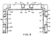
- Fig. 3 is an end view of the cable raceway duct coupler of Fig. 1;
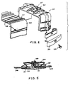
- Fig. 4 is an exploded view of a cable raceway duct system according to a second embodiment of the invention;
- Fig. 5 is a cross-sectional view of a duct retention barb member affixed to the duct coupler used to bias and retain the discrete sections of cable raceway duct within the coupler; and
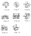
- Figs. 6-13 show various cable duct fittings that can also be affixed to each other or to a cable raceway duct by the cable raceway duct coupler.
-
- A first embodiment of a cable raceway duct system according to the invention will be described with reference to Figs. 1-3. The system includes a cable
raceway duct coupler 100 that joins various discrete cableraceway duct sections 200, which can take the form of straight raceway trough sections as shown or various cable raceway duct fittings as shown in Figs. 6-13, and aretention clip 300 that retains and locks the duct sections against thecoupler 100. - As better shown in Figs. 2-3, the
coupler 100 is shaped to correspond to and mate withduct sections 200. In the exemplary embodiments shown, the duct section and duct coupler are generally U-shaped. However, the invention is not limited to such shapes and may be formed from other shapes and configurations, i.e., circular, multi-sided, polygonal, etc., to form a cable receiving channel therebetween. The coupler can be formed from any rigid or semi-rigid material, such as metal or plastic. A preferred material is a molded or extruded plastic, such as acronitrile butadiene styrene (ABS). - The
coupler 100 has an inner wall consisting of twoside walls 110 and abottom wall 120, which are preferably integral and continuous. Asupport rib 130 outwardly extends from the U-shapcd inner wall and is substantially centrally disposed between forward andrearward edges 112, 114, respectively, of the inner wall. An axially extendingouter wall 140 is formed on thesupport rib 130.Outer wall 140 is outwardly spaced from theinner wall section receiving space 150 therebetween. - The
outer wall 140 is preferably formed from a plurality of discontinuous outer wall portions, such asportions 140A-F shown. The discontinuousouter wall portions 140A-F formopen spaces 170 therebetween. Alternatively, theopen spaces 170 could be formed by cutting or forming openings in a continuousouter wall 140 sized to receive theretention clip 300. Within one or more of these open spaces, preferably at three of these open spaces (one on each of the side walls and bottom wall), aclip mount 180 is provided for attachment ofretention clip 300. Themount clip 180 is preferably formed on thesupport rib 130. - The
outer wall portions 140A-F also act as guide elements to guide and constrain theduct elements 200 coupled by thecoupler 100. Theouter wall portions 140A-F may be reinforced by reinforcingribs 160 provided either axially, transversely or both on exterior surfaces of thewall portions 140A-F. - The
retention clip 300 will be further described with reference to Figs. 4-5.Retention clip 300 is preferably formed from a stamped metal or other resilient element and hasarms 310 that are bent inward.Retention clip 300 is attached toduct coupler 100 byfastener 400, which attachesclip 300 toclip mount 180. Fastener 400 can be any conventional fastener, but is preferably a threaded bolt. - Once
retention clip 300 is fully mounted onmounting clip 180,retention clip arms 310 extend into theduct receiving space 150 as shown in Fig. 5, with thearms 310 facing toward thecentral support rib 130. By this arrangement, an attachment end ofduct element 200, such as a trough or fitting, is able to be relatively easily slid into theduct receiving space 150 in one direction and constrained by theside walls 110, thebottom wall 120 and theouter wall portions 140A-F. Moreover, theretention clip 300 provides a retention force acting on the attachment ends of theduct elements 200 to resist disassembly of theduct element 200 from thecoupler 100 in an opposite direction. Most preferably, the retention force to resist disassembly is greater than the force to insert the duct element into thespace 150. - The retention force is created by a mechanical spring bias inherent in the
clip 300. By making the spring havearms 310 bent inward as shown,spring arms 310 are able to flex inwardly and allow the duct section to pass thereby in an insertion direction with minimal resistance. However, when the duct element is attempted to be removed in an opposite exit direction, the edges of the arms grab onto the duct section and the arms upon slight withdrawal of the duct section bend outwardly, which provides additional retention force onto the duct sections to resist further movement This retention force can be increased by making thearms 310 of the clip have a sharpened or serrated edge that will bite into theduct element 200, particularly if the duct element is attempted to be removed. Retention can be further increased by providingpliable engagement ribs 250 on external walls of theduct section 200, which upon application of the retention force deform inward preventing slippage of the duct section past thespring arms 310 and inadvertent removal of the duct sections. Thus, continued force in the exit direction results in further outward bending of the arms, which wedges the duct section even tighter against theinner wall 110. - Thus, a duct system is provided that can be easily assembled and prevented from inadvertent disassembly with a simple, reliable structure. Preferably, the duct coupler is pre-installed with the
retention clips 300 mounted in place on theclip mounts 180. This makes installation easier as all that is required is placement of the duct sections within theduct receiving space 150 of theduct coupler 100. Alternatively, the retention clips can be pre-installed in a partial mounting position where they are securely affixed to theclip mounts 180, but spaced in a retracted position such that thearms 310 are not within theduct receiving space 150. Then, upon full insertion of the duct sections into the space, theretention clips 300 can be fully tightened so that thearms 310 bias the duct section against the inner wall of the duct coupler. - The
duct coupler 100 is still capable of easy removal when desired by simply removingfastener 400, such as by unthreading when the fastener is a threaded bolt. By doing this, theretention 300 and spring are removable from the duct receiving space so that theducts 200 are freely removable from thecoupler 100. In this regard, it may not he necessary for theretention clip 300 to be completely removed fromduct coupler 100, but only sufficiently removed such thatclip arms 310 are no longer within theduct receiving space 150. Thus,fastener 400 may permanently affixretention clip 300 onto theduct coupler 100, but may be provided with detents that allow theretention clip 300 to be moved between an inserted position and a withdrawn position. - It may be desirable to provide a
cover 500, as shown in Fig. 4, to coverretention clip 300. Cover 500 should include a hole to receivefastener 400 therethrough. Alternatively, thecover 500 may include afastener 400 molded or otherwise formed on an underside thereof, which can be inserted into mountingclip 180. As such, the fastener will not be exposed. In this latter example, a hole is not necessary. - The
cover 500 supports theclip 300 so that an outward-facing surface of theretention clip 300 does not deform outward from theduct coupler 100 when force is applied to theretention clip 300. Thecover 500 can be of the same material and color asduct coupler 100 for a pleasing aesthetic appearance. Alternatively, thecover 500 could be plastic coated and colored to match the duct coupler or painted to match. - While the systems of the invention have been described in conjunction with the specific embodiments outlined above, it is evident that many alternatives, modifications and variations will be apparent to those skilled in the art. Accordingly, the exemplary embodiments are intended to be illustrative, not limiting. Various changes may be made without departing from the scope of the invention.
Claims (10)
- A cable duct coupler for coupling discrete cable duct sections together without the need for tools, comprising:an inner wall shaped to define a cable-receiving channel therebetween, said inner wall having a predefined axial length between forward and rearward edges;a support rib outwardly extending from said inner wall, said support rib being substantially centrally disposed between the forward and rearward edges of said inner wall, said support rib including at least one clip mount:an axially extending outer wall formed on said support rib, said axially extending outer wall being outwardly spaced from said inner wall by a predefined distance to define a duct section receiving space therebetween; andat least one removable retention clip matable with said clip mount through an open space provided in said outer wall, said retention clip having arms that extend into the duct section receiving space,wherein upon insertion of duct sections into said duct section receiving space, said at least one retention clip biases the duct sections against said inner wall to retain the duct sections together.
- The cable duct coupler of claim 1, wherein said inner wall is generally U-shaped and consists of a bottom wall portion and two side wall portions and preferably wherein three retention clips are provided, one for each of said bottom wall portion and said two side walls portions.
- The cable duct coupler of claim 1 or 2, wherein said axially extending outer wall is formed from a plurality of discrete outer wall portions forming said open space therebetween and preferably wherein said at least one retention clip and a corresponding said clip mount are provided at one or more of the open spaces.
- The cable duct coupler of any preceding claim, wherein said at least one removable retention clip is movable between an insert position in which said arms extend into said duct section receiving space to allow coupling and a detach position in which said arms no longer extend into said duct section receiving space to allow disassembly of the discrete duct sections and/or wherein said at least one retention clip is provided with a cover element.
- The cable duct coupler of claim 1, wherein said at least one retention clip is mated with said clip mount by a fastener and preferably wherein said fastener is a threaded bolt and/or wherein said at least one retention clip includes a hole through which said fastener passes to attach said at least one retention clip to said support rib, preferably further comprising a retention clip cover element provided with a hole, wherein said fastener passes through said hole to attach said at least one retention clip to said support rib.
- The cable duct coupler of any preceding claim wherein said at least one retention clip is formed of a resilient material and is bent to form arms that are angled towards said support rib of said duct coupler when installed and/or wherein said resilient material is metal and/or wherein each arm of the at least one retention member is sharpened or serrated at an edge thereof to increase retention of the duct section with the coupler.
- A cable duct system comprising the cable duct coupler of any preceding claim and at least one duct section.
- The cable duct system of claim 7, wherein said at least one duct section is a straight section of trough.
- The cable duct system of claim 7, wherein said duct section is a fitting and preferably wherein said fitting is one of a corner fitting, a T-fitting, and an X-fitting.
- The cable duct system of claim 7 wherein each arm of the at least one retention member is sharpened or serrated at an edge thereof to increase retention of the duct section with the coupler and preferably wherein said at least one duct section includes at least one pliable engagement rib that is engaged by said arms.
Applications Claiming Priority (2)
| Application Number | Priority Date | Filing Date | Title |
|---|---|---|---|
| US09/585,699 US6450458B1 (en) | 2000-06-01 | 2000-06-01 | Cable duct coupler with locking clip |
| US585699 | 2000-06-01 |
Publications (3)
| Publication Number | Publication Date |
|---|---|
| EP1160950A2 true EP1160950A2 (en) | 2001-12-05 |
| EP1160950A3 EP1160950A3 (en) | 2003-03-26 |
| EP1160950B1 EP1160950B1 (en) | 2008-11-19 |
Family
ID=24342581
Family Applications (1)
| Application Number | Title | Priority Date | Filing Date |
|---|---|---|---|
| EP01304535A Expired - Lifetime EP1160950B1 (en) | 2000-06-01 | 2001-05-23 | Cable duct coupler with locking clip |
Country Status (5)
| Country | Link |
|---|---|
| US (1) | US6450458B1 (en) |
| EP (1) | EP1160950B1 (en) |
| CN (2) | CN1303734C (en) |
| DE (1) | DE60136590D1 (en) |
| HK (1) | HK1044076A1 (en) |
Cited By (13)
| Publication number | Priority date | Publication date | Assignee | Title |
|---|---|---|---|---|
| EP1306951A1 (en) * | 2001-10-27 | 2003-05-02 | Panduit Corporation | Cable duct coupler |
| WO2003084018A1 (en) * | 2002-03-27 | 2003-10-09 | Adc Telecommunications, Inc. | Coupler for cable trough |
| US6709186B2 (en) | 2001-11-16 | 2004-03-23 | Adc Telecommunications, Inc. | Coupler for cable trough |
| US6715719B2 (en) | 2002-03-27 | 2004-04-06 | Adc Telecommunications, Inc. | Coupler for cable trough |
| US7315680B1 (en) | 2006-06-21 | 2008-01-01 | Adc Telecommunications, Inc. | Cable routing devices with integrated couplers |
| US7463809B2 (en) | 2007-02-21 | 2008-12-09 | Adc Telecommunications, Inc. | Coupler for cable trough |
| US7481597B2 (en) | 2007-02-21 | 2009-01-27 | Adc Telecommunications, Inc. | Coupler for cable trough |
| US7493005B2 (en) | 2007-02-21 | 2009-02-17 | Adc Telecommunications, Inc. | Coupler for cable trough |
| US7504583B2 (en) | 2007-02-21 | 2009-03-17 | Adc Telecommunications, Inc. | Coupler for cable trough |
| US7584929B2 (en) | 2007-02-21 | 2009-09-08 | Adc Telecommunications, Inc. | Coupler for cable trough |
| US7815152B2 (en) | 2007-02-21 | 2010-10-19 | Adc Telecommunications, Inc. | Coupler for cable trough |
| US7896295B2 (en) | 2007-02-21 | 2011-03-01 | Adc Telecommunications, Inc. | Coupler for cable trough |
| US8162267B2 (en) * | 2003-10-21 | 2012-04-24 | Panduit Corp. | Barb support |
Families Citing this family (33)
| Publication number | Priority date | Publication date | Assignee | Title |
|---|---|---|---|---|
| US20040103112A1 (en) * | 1999-10-08 | 2004-05-27 | Colson Thomas J. | Computer based method and apparatus for mining and displaying patent data |
| US6631875B1 (en) * | 2000-09-26 | 2003-10-14 | Adc Telecommunications, Inc. | Cable trough with separate side elements |
| WO2004017480A1 (en) * | 2002-08-19 | 2004-02-26 | Fox Ronald W | Cable trough |
| US7250574B2 (en) * | 2002-08-19 | 2007-07-31 | Fox Ronald W | Cable trough |
| SE523975E (en) * | 2002-10-10 | 2008-11-05 | Roxtec Ab | Frame |
| US6692186B1 (en) * | 2002-12-11 | 2004-02-17 | Fast Ditch, Inc. | Apparatus and method for transporting water |
| US6756539B1 (en) | 2003-03-20 | 2004-06-29 | Panduit Corp. | Adjustable mid-panel spillover fitting |
| US7246778B2 (en) * | 2003-03-27 | 2007-07-24 | Panduit Corp. | Releasable barb assembly |
| KR20050059267A (en) * | 2003-06-23 | 2005-06-17 | 홀로컴 네트웍스 | Secure conduit(pathway) system for telecommunications and communications transmission equipment, environmental analysis equipment, computer equipment and the like |
| US20060032152A1 (en) * | 2004-08-10 | 2006-02-16 | Awad Magdi M | Low clutter high flow gutter |
| US6951986B1 (en) * | 2004-12-29 | 2005-10-04 | Sbc Knowledge Ventures, L.P. | Adjustable routing device for routing fiber optic jumpers from fiber optic jumper raceways |
| FR2883108B1 (en) * | 2005-03-14 | 2007-06-08 | Icm Group Sa | WIRELESS ROAD CHURCH |
| DE202005010108U1 (en) * | 2005-06-28 | 2005-09-08 | Obo Bettermann Gmbh & Co. Kg | Connection between two cable carrying elements is in the form of a unit with spring arms that locate in slots |
| KR100745194B1 (en) | 2005-10-05 | 2007-08-01 | 주식회사 진우씨스템 | Connecting Apparatus of Duct for Wiring |
| US7471868B2 (en) | 2005-10-07 | 2008-12-30 | Adc Telecommunications, Inc. | Cable trough system and method |
| US7220923B1 (en) * | 2006-06-30 | 2007-05-22 | Internatioinal Metal Hose Company | Clip-on electrical conduit connector |
| US7453047B2 (en) * | 2006-11-07 | 2008-11-18 | Proverum Ag | Cable duct |
| US7742675B2 (en) * | 2007-01-26 | 2010-06-22 | Adc Telecommunications, Inc. | Cable trough system and method |
| US20080197243A1 (en) * | 2007-02-21 | 2008-08-21 | Adc Telecommunications, Inc. | Coupler for Cable Trough |
| US8733798B2 (en) * | 2009-02-05 | 2014-05-27 | Holocom, Inc. | Conduit connector device and conduit system |
| CN102789032B (en) * | 2011-05-20 | 2015-07-29 | 邓长霖 | The web member of trough of communication cable |
| US9297135B2 (en) | 2014-05-09 | 2016-03-29 | Fast Ditch, Inc. | Structural lining system |
| CN104466834B (en) * | 2014-12-08 | 2017-03-08 | 国家电网公司 | Cable trench joint |
| USD777115S1 (en) | 2015-09-25 | 2017-01-24 | Sumitomo Wiring Systems, Ltd. | Wire harness protector |
| JP1548602S (en) * | 2015-09-25 | 2016-05-09 | ||
| JP1548601S (en) | 2015-09-25 | 2016-05-09 | ||
| USD786198S1 (en) * | 2015-09-25 | 2017-05-09 | Sumitomo Wiring Systems, Ltd. | Wire harness protector |
| USD822615S1 (en) * | 2016-06-12 | 2018-07-10 | Jeffrey Baldwin | Corner cable conduit |
| DE202016104470U1 (en) * | 2016-08-12 | 2017-11-14 | Igus Gmbh | Connecting device and cable guide device |
| DE102017100566A1 (en) * | 2017-01-12 | 2018-07-12 | Krones Ag | Transport device and method for mounting a cable duct on a transport device |
| SE543763C2 (en) * | 2018-05-29 | 2021-07-13 | Concentus Properties Ab | A pipe shaft module and a method for mounting a pipe shaft module |
| USD954655S1 (en) * | 2020-01-02 | 2022-06-14 | The Siemon Company | Joiner for conduit for routing cable |
| FR3108210B1 (en) * | 2020-03-13 | 2022-04-01 | Legrand France | Section of cable tray s with a jointed end |
Citations (4)
| Publication number | Priority date | Publication date | Assignee | Title |
|---|---|---|---|---|
| US5035092A (en) * | 1990-08-13 | 1991-07-30 | Gsw Inc. | Nonsymmetrical eavestrough fitting |
| US5316243A (en) * | 1989-07-31 | 1994-05-31 | Adc Telecommunications, Inc. | Optic cable management |
| US5752781A (en) * | 1997-03-14 | 1998-05-19 | Adc Telecommunications, Inc. | Fiber trough coupling |
| US20020096606A1 (en) * | 2000-06-01 | 2002-07-25 | Bernard William A. | Cable duct coupler |
Family Cites Families (16)
| Publication number | Priority date | Publication date | Assignee | Title |
|---|---|---|---|---|
| US1682840A (en) * | 1927-04-12 | 1928-09-04 | Jr John W Foerch | Gutter joint |
| US1862433A (en) | 1930-12-12 | 1932-06-07 | William L Ross | Steel framework bracket |
| US3042351A (en) | 1960-05-27 | 1962-07-03 | Bois Marvin A Du | Cable trays |
| NL298903A (en) * | 1962-10-11 | |||
| US3351699A (en) | 1965-03-19 | 1967-11-07 | Danzer Metal Works Co | Raceway for electrical cables and wires adapted to retain rf energy |
| US3906146A (en) | 1974-02-06 | 1975-09-16 | Taylor Industries | Modular wiring duct and wire holder system |
| US4163572A (en) | 1977-11-07 | 1979-08-07 | Textron Inc. | Transition fitting |
| US4305236A (en) | 1980-01-14 | 1981-12-15 | Williams Robert F | Rain gutter system |
| US4306109A (en) | 1980-11-17 | 1981-12-15 | Gte Sylvania Canada Limited | Electrical wiring box arrangements |
| GB8725677D0 (en) | 1987-11-03 | 1987-12-09 | Swifts Of Scarborough Ltd | Cable trays |
| US4931597A (en) | 1988-12-12 | 1990-06-05 | Square D Company | Junction boxes |
| US5067678A (en) | 1989-07-31 | 1991-11-26 | Adc Telecommunications, Inc. | Optic cable management system |
| US4954015A (en) | 1990-04-04 | 1990-09-04 | Gsw Inc. | Gutter seal |
| US5038528A (en) | 1990-05-08 | 1991-08-13 | Gsw Inc. | Gasket seal |
| USD347209S (en) * | 1991-04-01 | 1994-05-24 | Adc Telecommunications, Inc. | Fiber trough coupling |
| GB2262192A (en) | 1991-11-28 | 1993-06-09 | Zortech Int | Insulated duct for electric cables |
-
2000
- 2000-06-01 US US09/585,699 patent/US6450458B1/en not_active Expired - Fee Related
-
2001
- 2001-05-23 DE DE60136590T patent/DE60136590D1/en not_active Expired - Lifetime
- 2001-05-23 EP EP01304535A patent/EP1160950B1/en not_active Expired - Lifetime
- 2001-05-31 CN CNB011211555A patent/CN1303734C/en not_active Expired - Fee Related
- 2001-05-31 CN CN2007100038776A patent/CN101009423B/en not_active Expired - Fee Related
-
2002
- 2002-05-31 HK HK02104189.1A patent/HK1044076A1/en unknown
Patent Citations (4)
| Publication number | Priority date | Publication date | Assignee | Title |
|---|---|---|---|---|
| US5316243A (en) * | 1989-07-31 | 1994-05-31 | Adc Telecommunications, Inc. | Optic cable management |
| US5035092A (en) * | 1990-08-13 | 1991-07-30 | Gsw Inc. | Nonsymmetrical eavestrough fitting |
| US5752781A (en) * | 1997-03-14 | 1998-05-19 | Adc Telecommunications, Inc. | Fiber trough coupling |
| US20020096606A1 (en) * | 2000-06-01 | 2002-07-25 | Bernard William A. | Cable duct coupler |
Cited By (27)
| Publication number | Priority date | Publication date | Assignee | Title |
|---|---|---|---|---|
| US8083187B2 (en) * | 2000-06-01 | 2011-12-27 | Panduit Corp. | Cable duct coupler |
| EP1306951A1 (en) * | 2001-10-27 | 2003-05-02 | Panduit Corporation | Cable duct coupler |
| US7360743B2 (en) | 2001-11-16 | 2008-04-22 | Adc Telecommunications, Inc. | Coupler for cable trough |
| US6709186B2 (en) | 2001-11-16 | 2004-03-23 | Adc Telecommunications, Inc. | Coupler for cable trough |
| US8186633B2 (en) | 2001-11-16 | 2012-05-29 | Adc Telecommunications, Inc. | Coupler for cable trough |
| US8444095B2 (en) | 2001-11-16 | 2013-05-21 | Adc Telecommunications, Inc. | Coupler for cable trough |
| US7175137B2 (en) | 2001-11-16 | 2007-02-13 | Adc Telecommunications, Inc. | Coupler for cable trough |
| US7029195B2 (en) | 2002-03-27 | 2006-04-18 | Adc Telecommunications, Inc. | Coupler for cable trough |
| US10114189B2 (en) | 2002-03-27 | 2018-10-30 | Commscope Technologies Llc | Coupler for cable trough |
| AU2003225975B2 (en) * | 2002-03-27 | 2008-07-17 | Adc Telecommunications, Inc. | Coupler for cable trough |
| US9104004B2 (en) | 2002-03-27 | 2015-08-11 | Adc Telecommunications, Inc. | Coupler for cable trough |
| US7093997B2 (en) | 2002-03-27 | 2006-08-22 | Adc Telecommunications, Inc. | Coupler for cable trough |
| US8365384B2 (en) | 2002-03-27 | 2013-02-05 | Adc Telecommunications, Inc. | Coupler for cable trough |
| US6715719B2 (en) | 2002-03-27 | 2004-04-06 | Adc Telecommunications, Inc. | Coupler for cable trough |
| US7614817B2 (en) | 2002-03-27 | 2009-11-10 | Adc Telecommunications, Inc. | Coupler for cable trough |
| WO2003084018A1 (en) * | 2002-03-27 | 2003-10-09 | Adc Telecommunications, Inc. | Coupler for cable trough |
| US8162267B2 (en) * | 2003-10-21 | 2012-04-24 | Panduit Corp. | Barb support |
| US7922129B2 (en) | 2006-06-21 | 2011-04-12 | Adc Telecommunications, Inc. | Cable routing devices with integrated couplers |
| US8256723B2 (en) | 2006-06-21 | 2012-09-04 | Adc Telecommunications, Inc. | Cable routing devices with integrated couplers |
| US7315680B1 (en) | 2006-06-21 | 2008-01-01 | Adc Telecommunications, Inc. | Cable routing devices with integrated couplers |
| US7896295B2 (en) | 2007-02-21 | 2011-03-01 | Adc Telecommunications, Inc. | Coupler for cable trough |
| US7815152B2 (en) | 2007-02-21 | 2010-10-19 | Adc Telecommunications, Inc. | Coupler for cable trough |
| US7584929B2 (en) | 2007-02-21 | 2009-09-08 | Adc Telecommunications, Inc. | Coupler for cable trough |
| US7504583B2 (en) | 2007-02-21 | 2009-03-17 | Adc Telecommunications, Inc. | Coupler for cable trough |
| US7493005B2 (en) | 2007-02-21 | 2009-02-17 | Adc Telecommunications, Inc. | Coupler for cable trough |
| US7481597B2 (en) | 2007-02-21 | 2009-01-27 | Adc Telecommunications, Inc. | Coupler for cable trough |
| US7463809B2 (en) | 2007-02-21 | 2008-12-09 | Adc Telecommunications, Inc. | Coupler for cable trough |
Also Published As
| Publication number | Publication date |
|---|---|
| DE60136590D1 (en) | 2009-01-02 |
| HK1044076A1 (en) | 2002-10-04 |
| CN101009423B (en) | 2010-06-23 |
| CN1328370A (en) | 2001-12-26 |
| CN1303734C (en) | 2007-03-07 |
| US6450458B1 (en) | 2002-09-17 |
| EP1160950A3 (en) | 2003-03-26 |
| CN101009423A (en) | 2007-08-01 |
| EP1160950B1 (en) | 2008-11-19 |
Similar Documents
| Publication | Publication Date | Title |
|---|---|---|
| EP1160950B1 (en) | Cable duct coupler with locking clip | |
| EP1306951B1 (en) | Cable duct coupler | |
| EP2795140B1 (en) | Cable tie mount | |
| US8403277B2 (en) | Electrical box mounting bracket | |
| CA2257755C (en) | Fiber optic cable capable metal raceway system | |
| US20070090245A1 (en) | Combination Spring Tension Rod and Mounting Brackets for Window Coverings | |
| US7118413B2 (en) | Quick assembling electrical connection box apparatus and method | |
| US6484360B1 (en) | Self-securing raceway end cap | |
| US7222394B2 (en) | Bushing for metal studs and the like | |
| CA2231941C (en) | Electrical outlet box and removable clamp therefor | |
| CA2551509C (en) | Pull out extension contained in electrical box | |
| US8273988B2 (en) | Cable management system | |
| US6679725B2 (en) | Clip-on cover plate for electrical fixtures | |
| US6840800B2 (en) | Deflecting securement anchor for electrical fixtures | |
| US7049511B2 (en) | Connection box stabilizer | |
| US7077695B2 (en) | Clip-on face plate for electrical fixtures | |
| US20070090246A1 (en) | Combination spring tension rod and mounting brackets for window coverings | |
| EP3680532B1 (en) | Plastic pipe clip | |
| US20040134678A1 (en) | Clip-on cover plate for electrical fixtures | |
| US7176378B1 (en) | Temporary attachment apparatus for an electrical box | |
| WO1998004023A1 (en) | Cable entry system | |
| AU733986B1 (en) | Connector for cable support apparatus | |
| EP1742317A2 (en) | Fast set screw device for non-metallic boxes |
Legal Events
| Date | Code | Title | Description |
|---|---|---|---|
| PUAI | Public reference made under article 153(3) epc to a published international application that has entered the european phase |
Free format text: ORIGINAL CODE: 0009012 |
|
| AK | Designated contracting states |
Kind code of ref document: A2 Designated state(s): AT BE CH CY DE DK ES FI FR GB GR IE IT LI LU MC NL PT SE TR |
|
| AX | Request for extension of the european patent |
Free format text: AL;LT;LV;MK;RO;SI |
|
| PUAL | Search report despatched |
Free format text: ORIGINAL CODE: 0009013 |
|
| AK | Designated contracting states |
Kind code of ref document: A3 Designated state(s): AT BE CH CY DE DK ES FI FR GB GR IE IT LI LU MC NL PT SE TR |
|
| AX | Request for extension of the european patent |
Extension state: AL LT LV MK RO SI |
|
| 17P | Request for examination filed |
Effective date: 20030829 |
|
| AKX | Designation fees paid |
Designated state(s): DE FR GB IT |
|
| 17Q | First examination report despatched |
Effective date: 20071015 |
|
| GRAP | Despatch of communication of intention to grant a patent |
Free format text: ORIGINAL CODE: EPIDOSNIGR1 |
|
| GRAS | Grant fee paid |
Free format text: ORIGINAL CODE: EPIDOSNIGR3 |
|
| GRAA | (expected) grant |
Free format text: ORIGINAL CODE: 0009210 |
|
| AK | Designated contracting states |
Kind code of ref document: B1 Designated state(s): DE FR GB IT |
|
| REG | Reference to a national code |
Ref country code: GB Ref legal event code: FG4D |
|
| REF | Corresponds to: |
Ref document number: 60136590 Country of ref document: DE Date of ref document: 20090102 Kind code of ref document: P |
|
| PLBE | No opposition filed within time limit |
Free format text: ORIGINAL CODE: 0009261 |
|
| STAA | Information on the status of an ep patent application or granted ep patent |
Free format text: STATUS: NO OPPOSITION FILED WITHIN TIME LIMIT |
|
| 26N | No opposition filed |
Effective date: 20090820 |
|
| REG | Reference to a national code |
Ref country code: HK Ref legal event code: WD Ref document number: 1044076 Country of ref document: HK |
|
| PG25 | Lapsed in a contracting state [announced via postgrant information from national office to epo] |
Ref country code: IT Free format text: LAPSE BECAUSE OF FAILURE TO SUBMIT A TRANSLATION OF THE DESCRIPTION OR TO PAY THE FEE WITHIN THE PRESCRIBED TIME-LIMIT Effective date: 20081119 |
|
| PGFP | Annual fee paid to national office [announced via postgrant information from national office to epo] |
Ref country code: DE Payment date: 20120529 Year of fee payment: 12 |
|
| PGFP | Annual fee paid to national office [announced via postgrant information from national office to epo] |
Ref country code: GB Payment date: 20130528 Year of fee payment: 13 |
|
| PGFP | Annual fee paid to national office [announced via postgrant information from national office to epo] |
Ref country code: FR Payment date: 20130606 Year of fee payment: 13 |
|
| PG25 | Lapsed in a contracting state [announced via postgrant information from national office to epo] |
Ref country code: DE Free format text: LAPSE BECAUSE OF NON-PAYMENT OF DUE FEES Effective date: 20131203 |
|
| REG | Reference to a national code |
Ref country code: DE Ref legal event code: R119 Ref document number: 60136590 Country of ref document: DE Effective date: 20131203 |
|
| GBPC | Gb: european patent ceased through non-payment of renewal fee |
Effective date: 20140523 |
|
| REG | Reference to a national code |
Ref country code: FR Ref legal event code: ST Effective date: 20150130 |
|
| PG25 | Lapsed in a contracting state [announced via postgrant information from national office to epo] |
Ref country code: FR Free format text: LAPSE BECAUSE OF NON-PAYMENT OF DUE FEES Effective date: 20140602 Ref country code: GB Free format text: LAPSE BECAUSE OF NON-PAYMENT OF DUE FEES Effective date: 20140523 |