EP1160896A2 - Electrode structure, battery and electrical double-layer capacitor and method of manufacturing same - Google Patents
Electrode structure, battery and electrical double-layer capacitor and method of manufacturing same Download PDFInfo
- Publication number
- EP1160896A2 EP1160896A2 EP01113010A EP01113010A EP1160896A2 EP 1160896 A2 EP1160896 A2 EP 1160896A2 EP 01113010 A EP01113010 A EP 01113010A EP 01113010 A EP01113010 A EP 01113010A EP 1160896 A2 EP1160896 A2 EP 1160896A2
- Authority
- EP
- European Patent Office
- Prior art keywords
- electrode
- current
- collecting member
- solvent
- battery
- Prior art date
- Legal status (The legal status is an assumption and is not a legal conclusion. Google has not performed a legal analysis and makes no representation as to the accuracy of the status listed.)
- Withdrawn
Links
Images


Classifications
-
- H—ELECTRICITY
- H01—ELECTRIC ELEMENTS
- H01M—PROCESSES OR MEANS, e.g. BATTERIES, FOR THE DIRECT CONVERSION OF CHEMICAL ENERGY INTO ELECTRICAL ENERGY
- H01M4/00—Electrodes
- H01M4/02—Electrodes composed of, or comprising, active material
- H01M4/04—Processes of manufacture in general
-
- H—ELECTRICITY
- H01—ELECTRIC ELEMENTS
- H01G—CAPACITORS; CAPACITORS, RECTIFIERS, DETECTORS, SWITCHING DEVICES OR LIGHT-SENSITIVE DEVICES, OF THE ELECTROLYTIC TYPE
- H01G11/00—Hybrid capacitors, i.e. capacitors having different positive and negative electrodes; Electric double-layer [EDL] capacitors; Processes for the manufacture thereof or of parts thereof
- H01G11/10—Multiple hybrid or EDL capacitors, e.g. arrays or modules
-
- H—ELECTRICITY
- H01—ELECTRIC ELEMENTS
- H01G—CAPACITORS; CAPACITORS, RECTIFIERS, DETECTORS, SWITCHING DEVICES OR LIGHT-SENSITIVE DEVICES, OF THE ELECTROLYTIC TYPE
- H01G11/00—Hybrid capacitors, i.e. capacitors having different positive and negative electrodes; Electric double-layer [EDL] capacitors; Processes for the manufacture thereof or of parts thereof
- H01G11/22—Electrodes
- H01G11/26—Electrodes characterised by their structure, e.g. multi-layered, porosity or surface features
- H01G11/28—Electrodes characterised by their structure, e.g. multi-layered, porosity or surface features arranged or disposed on a current collector; Layers or phases between electrodes and current collectors, e.g. adhesives
-
- H—ELECTRICITY
- H01—ELECTRIC ELEMENTS
- H01G—CAPACITORS; CAPACITORS, RECTIFIERS, DETECTORS, SWITCHING DEVICES OR LIGHT-SENSITIVE DEVICES, OF THE ELECTROLYTIC TYPE
- H01G11/00—Hybrid capacitors, i.e. capacitors having different positive and negative electrodes; Electric double-layer [EDL] capacitors; Processes for the manufacture thereof or of parts thereof
- H01G11/22—Electrodes
- H01G11/30—Electrodes characterised by their material
-
- H—ELECTRICITY
- H01—ELECTRIC ELEMENTS
- H01G—CAPACITORS; CAPACITORS, RECTIFIERS, DETECTORS, SWITCHING DEVICES OR LIGHT-SENSITIVE DEVICES, OF THE ELECTROLYTIC TYPE
- H01G11/00—Hybrid capacitors, i.e. capacitors having different positive and negative electrodes; Electric double-layer [EDL] capacitors; Processes for the manufacture thereof or of parts thereof
- H01G11/84—Processes for the manufacture of hybrid or EDL capacitors, or components thereof
- H01G11/86—Processes for the manufacture of hybrid or EDL capacitors, or components thereof specially adapted for electrodes
-
- H—ELECTRICITY
- H01—ELECTRIC ELEMENTS
- H01M—PROCESSES OR MEANS, e.g. BATTERIES, FOR THE DIRECT CONVERSION OF CHEMICAL ENERGY INTO ELECTRICAL ENERGY
- H01M4/00—Electrodes
- H01M4/02—Electrodes composed of, or comprising, active material
- H01M4/04—Processes of manufacture in general
- H01M4/0402—Methods of deposition of the material
- H01M4/0404—Methods of deposition of the material by coating on electrode collectors
-
- H—ELECTRICITY
- H01—ELECTRIC ELEMENTS
- H01M—PROCESSES OR MEANS, e.g. BATTERIES, FOR THE DIRECT CONVERSION OF CHEMICAL ENERGY INTO ELECTRICAL ENERGY
- H01M4/00—Electrodes
- H01M4/02—Electrodes composed of, or comprising, active material
- H01M4/04—Processes of manufacture in general
- H01M4/0402—Methods of deposition of the material
- H01M4/0409—Methods of deposition of the material by a doctor blade method, slip-casting or roller coating
-
- Y—GENERAL TAGGING OF NEW TECHNOLOGICAL DEVELOPMENTS; GENERAL TAGGING OF CROSS-SECTIONAL TECHNOLOGIES SPANNING OVER SEVERAL SECTIONS OF THE IPC; TECHNICAL SUBJECTS COVERED BY FORMER USPC CROSS-REFERENCE ART COLLECTIONS [XRACs] AND DIGESTS
- Y02—TECHNOLOGIES OR APPLICATIONS FOR MITIGATION OR ADAPTATION AGAINST CLIMATE CHANGE
- Y02E—REDUCTION OF GREENHOUSE GAS [GHG] EMISSIONS, RELATED TO ENERGY GENERATION, TRANSMISSION OR DISTRIBUTION
- Y02E60/00—Enabling technologies; Technologies with a potential or indirect contribution to GHG emissions mitigation
- Y02E60/10—Energy storage using batteries
-
- Y—GENERAL TAGGING OF NEW TECHNOLOGICAL DEVELOPMENTS; GENERAL TAGGING OF CROSS-SECTIONAL TECHNOLOGIES SPANNING OVER SEVERAL SECTIONS OF THE IPC; TECHNICAL SUBJECTS COVERED BY FORMER USPC CROSS-REFERENCE ART COLLECTIONS [XRACs] AND DIGESTS
- Y02—TECHNOLOGIES OR APPLICATIONS FOR MITIGATION OR ADAPTATION AGAINST CLIMATE CHANGE
- Y02E—REDUCTION OF GREENHOUSE GAS [GHG] EMISSIONS, RELATED TO ENERGY GENERATION, TRANSMISSION OR DISTRIBUTION
- Y02E60/00—Enabling technologies; Technologies with a potential or indirect contribution to GHG emissions mitigation
- Y02E60/13—Energy storage using capacitors
-
- Y—GENERAL TAGGING OF NEW TECHNOLOGICAL DEVELOPMENTS; GENERAL TAGGING OF CROSS-SECTIONAL TECHNOLOGIES SPANNING OVER SEVERAL SECTIONS OF THE IPC; TECHNICAL SUBJECTS COVERED BY FORMER USPC CROSS-REFERENCE ART COLLECTIONS [XRACs] AND DIGESTS
- Y10—TECHNICAL SUBJECTS COVERED BY FORMER USPC
- Y10T—TECHNICAL SUBJECTS COVERED BY FORMER US CLASSIFICATION
- Y10T29/00—Metal working
- Y10T29/49—Method of mechanical manufacture
- Y10T29/49002—Electrical device making
- Y10T29/49108—Electric battery cell making
- Y10T29/49115—Electric battery cell making including coating or impregnating
Definitions
- the present invention relates to a novel method of manufacturing an electrode structure, and to a manufacturing method for producing a battery and an electrical double-layer capacitor utilizing the electrode structure.
- a typical electrode structure of the prior art is manufactured by coating a current-collecting member surface with a compound mixture containing an electrode material, a powdered electrically-conducting substance, binder and solvent, vaporizing the solvent by directing hot air flow, and drying the coating to attach an electrode film to the surface of the current-collecting member.
- the electrode film is prone to peel away from the current-collecting member and as a consequence the electrical resistance of the electrode film does not decrease.
- hot air flow is generated by a hot air heater utilizing outside air of 80-200 °C at 15-25 m/second.
- the hot air heater is configured such that electrode structures containing an electrode film h coated on a current-collecting member g is moved by the conveyor d into the cabinet c and hot air flow f is directed onto the electrode film h from a hot air outlet to vaporize the solvent involved.
- the hot air flow moves the solvent outwards by way of the cabinet outlet e.
- An object of this invention is to provide an electrode film that adheres well to the current-collecting member.
- Another object of this invention is to provide an electrode film with low electrical resistance.
- Another object of this invention is to provide a battery or double-layer capacitor with an electrode film having low electrical resistance and good bonding.
- This invention relates to a method of manufacturing an electrode structure by coating a compound mixture comprising an electrode material, binder, and solvent onto a current-collecting member, directing warm breeze onto the compound mixture coating to vaporize the solvent and form an electrode film on the current-collecting member.
- the electrode structure of this invention can be used in the electrodes of electronic components wherein typically an electrolyte is provided between the electrodes.
- the electrical component is a battery
- the electrode structure exchanges electricity by way of electrolyte ions.
- the electrical component is a double-layer capacitor
- the electrode structure forms an electrical double-layer between a material with a large surface area and electrolyte.
- FIG. 1(A) illustrates examples of typical electrode structures.
- the electrode structure of FIG. 1(A) is used as the positive electrode of a battery.
- the electrode structure 1 is an electrode film 18 consisting of an electrode active material as an electrode material 11, an electrically-conductive material 14, and binder 17, attached to the surface of the current-collecting member 13.
- LiCoO 2 i.e., the powdered electrode active substance, for example, is used as the electrode active material.
- FIG. 1(B) an ion-conducting polymer 12 is attached to the powered electrode material 11 of FIG. 1(A).
- the ion-conducting polymer 12 also acts as a binder.
- FIG. 1(C) shows an electrode structure used in the negative electrode of a battery.
- the electrode structure 1 is an electrode film 18 consisting of a powdered electrode active substance as an electrode material 11 and a binder 17, attached to the surface of the current-collecting member 13.
- graphite powder is, for example, used as the powdered electrode active substance.
- FIG. 1(D) is the electrode material of FIG. 1(C) coated with the ion-conducting polymer 12. This ion-conducting polymer also functions as a binder.
- the electrode structure is used as an electrode for the double-layer capacitor.
- the electrode structure 1 is an electrode film 18 consisting of a large surface area material as an electrode material 11 and a binder 17, attached to the surface of the current-collecting member 13.
- active carbon material i.e., powdery high surface area material
- large surface area material i.e., powdery high surface area material
- an ion-conducting polymer 12 is attached to the powdery high surface area material of FIG. 1(E). This ion-conducting polymer also functions as a binder. When the electrode material 11 is covered with the ion-conducting polymer 12, this ion-conducting polymer functions as a binder. The electrode material covered with the ion-conducting polymer is described in detail later on.
- FIG. 2 An example of the manufacturing method of this invention to produce an electrode structure is shown in FIG. 2.
- the electrode material 11, electrically-conductive material 14, binder 17, and solvent 19 are mixed together by slurrying in a mixer 3 to obtain the mixed material 31.
- the mixed material 31 is lightly coated onto the surface of the current-collecting member 13.
- the method for coating the mixed material 31 may proceeded by a doctor knife applicator.
- the solvent of the mixed material coating is vaporized by brez/air heating, and the material coating dried and attached to the current-collecting member 13 as the electrode film 18.
- this invention provides the same advantages as an electrode film obtained through the method of drying the mixed material coating by infrared radiation as disclosed in Japanese Patent Application No. 2000-32279 by the present inventors.
- Brez/Air heating is a heating method for drying the mixed material 31 and is conducted by directing brez/air with heat, i.e., warm breeze 51, to the mixed material 31.
- a brez/air heater 51 is a device used to heat an object by blowing air, wherein the brez/air with heat, i.e., the warm breeze 51, is directed onto the mixed material to dry the mixed material into electrode film 18.
- the brez/air is injected from an outside air inlet 59, dried by a dry air generator 58, and heated by an air heater 52, and the warm breeze 51 is injected into the cabinet 56 via a guide tube 53.
- the electrode film 18 coated on the current-collecting member 13 is moved within the cabinet 56 by a conveying means such as a conveyer 55.
- the warm breeze 51 is directed onto the electrode film 18, vaporizes the solvent involved in the electrode film 18, and is subsequently directed into the solvent collector 57 via ducts 54, thereby collecting the vaporized solvent.
- the warm breeze 51 after removing the solvent is exhausted from partial ducts 60, and the rest of the air is returned into the dry air generator 58.
- the warm breeze 51 in this invention preferably is a gas flow such as an air flow of 60-150 °C at 0.1-3m/second or lower.
- FIG. 4 shows an enhanced view of the internal state of the mixed material 31 when the solvent 19 of the mixed material coated on the current-collecting member 13 is vaporized.
- FIG. 4(A) shows the conventional method of applying hot air flow f of 80-200 °C at 15-25 m/second onto the mixed material 31 to vaporize the solvent 32 mixed with a binder.
- FIG. 4(B) shows the method of this invention wherein the warm breeze 51 of 60-150 °C at 1-3m/second, is directed onto the mixed material 31 to vaporize the solvent 32 mixed with a binder.
- the solvent vaporization process works as follows in the case of the conventional method of directing the hot air flow f of FIG. 4(A). First, when hot air flow f is applied to the surface of the mixed material, the area around the surface of the mixed material 31 suddenly warms up in the hot air flow f, and the solvent on the surface is vaporized and blown away by the hot air flow f.
- the solvent near the surface therefore quickly vaporizes, and to compensate, the solvent at the interior of the mixed material and near the collector electrode moves to the vicinity of the surface
- the binder contained in the solvent and the powdered conducting material are at this time carried to the surface of the mixed material 31 along with the solvent. That is, migration of the binder and the powdered conducting material occurs.
- the binder concentration of the mixed material in the vicinity of the current-collecting member 13 and the powdered conducting material concentration become thin.
- the electrode film therefore tends to easily peel away from the current-collecting member 13; the relative electrical resistance in the vicinity of the current-collecting member becomes high; and the resistance of the electrode overall becomes high.
- the solvent vaporization process works as follows.
- the warm breeze 51 When the warm breeze 51 is directed onto the mixed material surface, the warm breeze 51 gradually heats up the entire mixed material and gradually vaporizes the solvent from the mixed material surface.
- the concentrations of binder and powdered conducting material 14 therefore remain uniform overall. That is, migration of the binder and the powdered conducting material is prevented.
- the binder concentration in the vicinity of the current-collecting member 13 does not become weak (or thin) in the electrode material of dried mixed material 31. Accordingly, the electrode film adheres well to the current-collecting member 13. Further, the concentration of the powdered conducting material in the vicinity of the current-collecting member 13 does not become weak either, so that the electrical resistance of the overall electrode film is low.
- the current-collecting member 13 may be any material capable of conducting electricity, and the material and shape can be selected according to the electronic component containing member 13.
- the electrically-conductive material may be aluminum or copper and formed into a plate, leaf or mesh shape. When the current-collecting member is a plate or leaf shape, one or both sides are used according to the structure of the electronic component.
- the electrode film 18 for adhering to the current-collecting member 13 may be pressed into the current-collecting member to make it further adhere.
- a fixing device 4 as shown in Fig. 10 is used.
- An electrode structure 1 made from current-collecting member coated with mixed material is enclosed by the pressure rollers 41.
- Electrode film can be bonded to the current-collecting member by applying a rotating pressure with the pressure device 43 and by means of the backroller 42 applied against pressure rollers 41.
- the fixing or adhesion device 4 is not limited to a four-roller device and is sufficient as long as it presses and adheres the electrode film to the current-collecting member .
- a two-roller press device may be appropriate.
- FIG. 1(A) or FIG. 1(B) can be used as the positive electrode while an electrode structure useful as a negative electrode is shown in FIG. 1(C) or FIG. 1(D).
- An electrolyte may be positioned between the respective electrode structures.
- FIG. 5 shows an example in which a battery comprises an electrode structure of FIG. 1(B) as the positive electrode and an electrode structure of FIG. 1(D) as the negative electrode.
- FIG. 5(A) shows the case when the electrolyte is a liquid electrolyte 16, and a separator 15 is placed between the electrodes.
- FIG. 5(B) shows the case when the electrolyte is an ion-conducting polymer 12 in solid.
- the separator 15 is installed to isolate one pair of electrode structures 1, and the electrolyte can be used in solid when required according to circumstances.
- the double-layer capacitor has a structure with electrolyte placed between one pair of electrodes of the electrode structure of FIG. 1(E) or one pair of electrodes of the electrode structure of FIG. 1(F).
- a double-layer capacitor utilizing the electrode structure of FIG. 1(E) is shown in FIG. 6(A)
- a double-layer capacitor utilizing the electrode structure of FIG. 1(F) is shown in FIG. 6(B).
- FIG. 6(A) shows the case when the electrolyte is a liquid electrolyte 16, and a separator 15 is placed between the electrodes.
- FIG. 6(B) shows the case when the electrolyte is an ion-conducting polymer 12 in solid.
- the separator 15 is installed to isolate one pair of electrode structures 1, and the electrolyte can be used in solid when required according to circumstances.
- Electrode structure sample pieces 1 - 8 were dried using two types of heating methods; one method was the hot air flow method of the prior art and the other was breezing/air heating method of this invention. The peeling strength and impedance ( ⁇ /ohm) of these sample pieces were measured. A battery using the electrode structures was prepared and a cycle degradation was measured. The ratio (proportions) of electrode material, conductive material, binder, and solvent material used in the preparation of the sample pieces are shown in Table 1.
- Samples 1 through 6 represent electrodes useful for capacitors.
- the electrode material was made from phenol active carbon (made by Kansai Chemical Corp.) which was dry mixed with carbon black, i.e., the powdered conductive material, as the conductive material, utilizing a mixer.
- Samples 7 through 8 represent positive electrodes for batteries. Carbon black of the powdered conductive material as the electrode was added to LiCoO 2 of the powdered electrode active substance which served as the electrically-conductive material by dry type mixing performed utilizing a mixer. The binder was then added to all the samples 1 through 8 and mixing performed. A specified amount of solvent was further added and mixing was performed. After mixing, the material was coated onto the collector element with a doctor knife applicator. The samples were then dried by brez/air heating or conventional hot air heating.
- the samples 1 to 6 utilized active carbon material as the electrode material.
- Sample 7 utilized LiCoO 2 as the electrode material and PVDF (polyvinylidene fluoride) as the binder.
- Sample 8 utilized LiCoO 2 as the electrode material and polymer A2 as the binder, and was covered with ion-conducting polymer.
- Samples 1 through 4 contained no carbon black powdered electrically-conducting substance, and samples 5 through 11 contained carbon black though there were differences in the concentrations used in the samples.
- Polymer A1, polymer A2, Teflon powder, and PVDF were used as the binders.
- Polymer A1 and polymer A2 were ion-conducting polymers. The raw materials used to form polymers A1 and A2 are shown in Table 2 and Table 3, respectively.
- the air heater 52, the ancillary dry air generator 58, and the solvent collector 57 are driven to generate dry air.
- the warm breeze is supplied into the cabinet 56 at 1 m/second (approximately minimum of 0.5-maximum 1.5 m/second)
- An area within the cabinet 56 wherein the warm breeze is flown through is divided into a first zone keeping the warm breeze approximately at 80 °C and a second zone keeping the warm breeze approximately at 100 °C.
- the sample material is supplied into the first zone then into the second zone at 3 m/minute.
- Length of the first and second zones each is approximately 4.5 m (total of 9 m), the time required for the air to flow though is approximately 3 minutes, and the mixed material is dried for 3 minutes. As such, the mixed material was dried so that migration of the binder and the powdered conducting material may be prevented.
- a device as shown in FIG. 11 was utilized for the hot air heating, where outside air within a room is drawn from outside of the device.
- the hot air flow had a 60 % relative humidity and was directed at the sample at 15m/second for 3 minutes to dry the mixed material.
- the same procedure as in brez/air heating was performed except for the wind velocity and drying of the hot air flow.
- the hot air flow of dried outside air as in this invention was also tested. That is, all the same steps in the above hot air flow heating are used except for the dry air instead of outside air (having 60 % relative humidity).
- cellophane tape (KOKUYO TSS18N width 18 mm, thickness 50 ⁇ m) was attached to the electrode film fabricated on the surface of the current-collecting member, and the cellophane tape was then pulled away to make the electrode film stuck onto the cellophane tape separate from the current-collecting member.
- a peeling strength ranking could then be established according to the tape separate from the current-collecting member.
- a peeling strength ranking could then be established according to the amount of electrode film peeled from the surface of the current-collecting member.
- FIG. 7 taken from photographs shows the electrode film stuck to the cellophane tape.
- FIG. 7(A) taken from photographs shows a small flaked portion of the upper electrode film, which is ranked a. (The blacken portion in the photograph is the flaked portion of the electrode film.)
- FIG. 7(B) taken from photographs shows a small flaked portion of the middle electrode film, which is ranked b. (The blacken portion in the photograph is the flaked portion of the electrode film.)
- FIG. 7(C) taken from photographs shows an electrode film completely peeled from the current-collecting member, which is ranked c. (The blacken portion in the photograph is the flaked portion of the electrode film.) For samples measurement, the results of peeling strength and impedance ( ⁇ /ohm) are shown in Table 4.
- the electrodes formed on the collector element were enclosed by copper plates of 2 centimeters in diameter and 5 millimeters thick. A pressure of 4.5 kilograms per centimeter was applied from above and below, and the resistance at 10 kilohertz AC was measured with an impedance analyzer.
- An electrode prepared according to the above-embodiment was used to prepare a battery, and Table 5 shows comparison results of dry brez/air heating, outside hot air heating, and dry hot air heating.
- a lithium ion battery was prepared by combining the positive electrode using LiCoO 2 obtained through brez/air heating and hot air heating (including outside air and dry air) of sample 7 as an active material and a negative electrode using graphite as an active material, which was used as test samples. Charging and discharging were performed using the test samples.
- the electrode thus obtained had a thickness of 80 ⁇ m.
- the battery had a separator between the positive electrode having an electrode film of 0.94 cm 2 on one surface and the negative electrode having an electrode film of 0.94 cm 2 on one surface in order to prepare a coincell. Electrolyte was filled up to prepare a test cell. EC/DEC(1/1)V/V solution dissolving 1.0 M of LiPF 6 was used as electrolyte.
- electrode materials within the electrode When air with relatively higher humidity is heated to prepare an electrode, electrode materials within the electrode sometime absorb moisture. Especially for a battery and an electrical double-layer capacitor used with high voltage (i.e., 1.5 V or more), a trace of moisture absorbed may cause electrolysis within the electrode to generate hydrogen and oxygen. As a result of the above
- LIPF 6 and LiBF 4 may be used as the ion conductive salt. Since these materials react with a trace of moisture and generate HF, HF generated corrodes a wide variety of materials to cause cycle degradation. Accordingly, zero temperature of air as dry air should be -10 °C or lower, preferably -20 °C or lower, more preferably -40 °C or lower and most preferably -50 °C or lower.
- the condition for charging should be such that charging is first conducted at a charging current of 0.21-0.26 mA/cm 2 , secondly, maintaining a charging voltage of 4.2 V for two hours upon reaching 4.2 V, and thirdly, pausing the charging for ten minutes.
- the condition for discharging should be such that discharging is conducted at a discharging current of 0.21-0.26 mA/cm 2 up to 2.7 V of final voltage and pausing the discharging for ten minutes. Charging and discharging are repeated under room temperature.
- the electrode material coated with ion-conducting polymer is described next.
- the powdered electrode active substance 11 has the shape of particles consisting of bonded particles like LiCoO 2 .
- the process for depositing the ion-conducting polymer 12 is also shown.
- “adhere” or “adhesion” means that ions are attached in such manner that the ions can migrate between the ion conductive polymer 12 and the entire surface of the powdery electrode material. It means that the ion conductive polymer 12 adheres to the surface of the powdery electrode material 11 and covers it with the ion conductive polymer 12.
- the activity is suppressed and can be turned a to more stable state.
- the deposit of ion-conducting polymer 12 is thick, the electrical conduction decreases, and the current (charge) collection is poor.
- the powder shape such as for the powdered electrode active substance 11 and powdered conducting material 14 is a fine particle substance. Further, such a powder is a collection of many substances. In certain cases, this fine particle substance refers to a state wherein a large number of substances in a fine particle state constitute an agglomeration.
- the powdered electrode active substance uses ion insertable-separable materials and ⁇ -conjugated conductive macromolecular materials.
- the electrode active substance used as the positive electrode for non-aqueous electrolyte batteries there are no particular restrictions on the electrode active substance used as the positive electrode for non-aqueous electrolyte batteries.
- chalcogen compounds allowing ion insertion/separation or composite chalcogen compounds containing lithium are recommended.
- the chalcogen compound having lithium as described above includes LiCoO 2 , LixNiyM 1 -yO 2 (where M represents at least one type of metal element selected from transition metal or aluminum, or more preferably, it represents at least one type of metal element selected from Co, Mn, Ti, Cr, V, or Al, and 0.05 ⁇ x ⁇ 1.10 and 0.5 ⁇ y ⁇ 1.0), LiNiO 2 , LiMnO 2 , LiMn 2 O 4 , etc.
- oxide, salt or hydroxide of lithium, cobalt, nickel or manganese as starting materials, these starting materials are mixed in adequate composition, and the mixture is fired in the temperature range of 600 °C - 1000 °C under oxygen atmosphere.
- the electrode active substance used as the negative electrode for non-aqueous electrolyte batteries there are no particular restrictions on the electrode active substance used as the negative electrode for non-aqueous electrolyte batteries. However, a material allowing lithium ion insertion/separation may be used, and lithium metal, lithium alloys (alloys such as lithium and aluminum, lead, indium) and carbon quality materials may be utilized.
- Polyacetylene types polyaniline types, polypyrrole types, polythiophene types, poly- ⁇ (para)-phenylene types, polycarbazole types, polyacene types and sulfur polymer types are among the useful ⁇ -conjugated conductive macromolecular materials.
- lithium metals in the negative electrode achieves a large battery capacity particularly in primary non-aqueous electrolyte batteries.
- carbon materials in the negative electrodes that are capable of lithium ion insertion/separation yields a longer battery cycle life span.
- carbon material used but materials such as pyrolytic carbon types, coke types (pitch coke, needle coke and petroleum coke, etc.) graphite types, glass carbon types, organic macromolecular compound fired products (carbonized pieces baked to a suitable temperature such as phenol resin and furan resin) carbon fibers and active carbon may be utilized.
- the powdered electrically-conducting substance raises the conductivity of the electrode structure and though there are no particular restrictions, materials such as metal powder and carbon powder may be used.
- materials such as metal powder and carbon powder may be used.
- preferred carbon powders are pyrolytic carbons such as carbon black, and their graphite products, artificial and natural scaly graphite powder, carbon fibers and their graphite products, etc. Product mixtures of these carbon powders are also utilized.
- the ion conductive polymer is a polymer, which can dissolve at least an ion conductive salt such as lithium salt at concentration of 0.1 M (mol/l) or more shows an electrical conductivity of 10 -8 S (Siemens)/cm or more at room temperature.
- it is an ion conductive polymer, which dissolves at least ion conductive salt such as lithium salt and exhibits electrical conductivity of 10 -2 S/cm - 10 -5 S/cm at room temperature.
- the lithium salt is at least one type of lithium salt having ClO 4 - , CF 3 SO 3 - , BF 4 - , PF 6 - , AsF 6 - , SbF 6 - , CF 3 CO 2 - or (CF 3 SO 2 ) 2 N - as anion.
- the ion-conducting polymer raw material is a substance which produces the ion-conducting polymer by polymerizing, crosslinking, etc., when energy is supplied externally.
- the raw material itself may be a polymer.
- the energy may be heat, ultraviolet light, light or electron radiation.
- the method of coating the powdered conductive material with the ion-conducting polymer as is shown in Fig. 8 is to press-slide the ion-conducting polymer and the powdered electrode active substance against each other.
- the particle surfaces of the powdered electrode active substance are coated with the ion-conducting polymer, no voids are formed, and gaps in the powdered substance are reduced.
- Press-sliding is the action of sliding while pressing mixtures 10 of the ion-conducting polymer 12 or the raw material of the ion-conducting polymer 12 and the powdered substance 11 together. An external force is applied to the mixtures so that they cohere to each other and the particles rotate, and this process is performed repeatedly to obtain a press-sliding product.
- the press-sliding and kneading mixer is shown, for example, in Fig. 9(A).
- the mixture 10 of the ion conductive polymer 12 and the powdered material 11, or a mixture containing this mixture and a mixture 10 containing solvent, is placed in a container 21, and a main blade 22 is rotated. There is a gap between a bottom 211 of the container 21 and the main blade 22.
- a part of the mixture 10 is moved between the bottom 211 of the container 21 and the main blade 22. It is subject to press-sliding and kneading. This process is repeated to coat the ion-conducting polymer 12 on the powdered substance 11.
- a press-sliding mixer 2 may if necessary be provided with a dispersion blade 23 in the container 21. The dispersion blade 23 is rotated at high speed via motor 231 to disperse the press-slide mixture 10.
- the container 21 is provided for holding the mixture 10 which is press-slid and stirred.
- a lower portion 2111 with a part of it at lower position.
- the bottom surface is inclined upward as it goes toward the peripheral portion of container 21. For instance, the bottom surface is lower at the center, and gradually goes up toward the periphery.
- the bottom 211 is formed in the shape of a conical mortar.
- the inclination angle of the lower portion 2111 is set to 150 °C, for example.
- the bottom 211 of the container is wear-resistant, and can be formed by thermal spraying with tungsten or carbide using SUS. Plural bottom parts of this type may also be formed on the bottom surface 2111.
- the main blade 22 functions together with the bottom surface 211 of the container 21, serving to press-slide and stir the mixture 10.
- the main blade 22, is positioned via shaft 221 to the desired location relative to the bottom 211 of the container 21 as shown for example in Figs. 9(A) and 9(B).
- the main blade 22 curves upwards corresponding to the slant of bottom 211 of the container 21.
- the main blade 22 may comprise two blades attached from the center part as shown in Fig. 9(B), or it may comprise a larger number of blades, e.g. 10 or more, depending on the amount and type of mixture.
- the number of rotations of a main motor 222 driving the main shaft 221 is set low for example to 120 rpm or less, when press-sliding is performed.
- the gap between the bottom surface 211 of the container 21 and the base surface of the main blade 22 is set as narrow as is necessary for press-sliding the mixture, for example 15 mm or less. This distance depends on the capacity of the press-sliding mixer 2 and on the shape of the main blade, etc.
- the surface in the motion direction (press-sliding direction) of the main blade 22 is formed so that a pressing angle ⁇ relative to the bottom surface of the container 21 is an acute angle.
- a pressing angle ⁇ relative to the bottom surface of the container 21 is an acute angle.
- the cross-section of the main blade 22 is a reverse trapezoid as shown in Fig. 9(C)
- the pressing angle is from 3-70 degrees.
- the cross-section of the main blade 22 may also be circular or have a rounded corner as shown in Fig. 9(D).
- the material of the main blade has wear-resistant properties, and is formed for example by thermal spraying with tungsten or carbide using SUS.
- the surface of the main blade 22 opposite to the advancing direction is designed in such manner that it runs almost perpendicularly to the bottom surface and at acute angle. As a result, when the main shaft 221 is rotated in reverse direction, the mixture 10 can be collected on the periphery of the main shaft 221.
- the center parts of the main blade 22 are also disposed in positions of the bottom part corresponding to their number.
- the dispersion blade 23 disperses the mixture 10 which is press-slid by the main blade 22.
- the dispersion blade 23 is disposed in a position at which the mixture 10 can be dispersed, and it rotates at a high speed such as 1000-4000 rpm. Due to this high speed rotation, the ion-conducting polymer 12 or its raw material coated on the particle surfaces of the powdered substance 11 uniformly disperses through the whole of the powdered substance.
- An electrode film that adheres well to the current-collecting member can be obtained.
- An electrode film with low electrical resistance can be obtained.
- a battery or double-layer capacitor with an electrode film having low electrical resistance and good bonding can be obtained.
Abstract
Description
- The present invention relates to a novel method of manufacturing an electrode structure, and to a manufacturing method for producing a battery and an electrical double-layer capacitor utilizing the electrode structure.
- A typical electrode structure of the prior art is manufactured by coating a current-collecting member surface with a compound mixture containing an electrode material, a powdered electrically-conducting substance, binder and solvent, vaporizing the solvent by directing hot air flow, and drying the coating to attach an electrode film to the surface of the current-collecting member. Unfortunately, the electrode film is prone to peel away from the current-collecting member and as a consequence the electrical resistance of the electrode film does not decrease. Here, hot air flow is generated by a hot air heater utilizing outside air of 80-200 °C at 15-25 m/second.
- For example as shown in Figure 11, the hot air heater is configured such that electrode structures containing an electrode film h coated on a current-collecting member g is moved by the conveyor d into the cabinet c and hot air flow f is directed onto the electrode film h from a hot air outlet to vaporize the solvent involved. The hot air flow moves the solvent outwards by way of the cabinet outlet e.
- An object of this invention is to provide an electrode film that adheres well to the current-collecting member.
- Another object of this invention is to provide an electrode film with low electrical resistance.
- Another object of this invention is to provide a battery or double-layer capacitor with an electrode film having low electrical resistance and good bonding.
- This invention relates to a method of manufacturing an electrode structure by coating a compound mixture comprising an electrode material, binder, and solvent onto a current-collecting member, directing warm breeze onto the compound mixture coating to vaporize the solvent and form an electrode film on the current-collecting member.
- The above and other objects and advantages of the present invention will become readily apparent by reference to the following detailed description when considered in conjunction with the accompanying drawings.
- FIGS.1A to 1F
- are plan views showing different types of electrode structures;
- FIG. 2
- is a schematic view of the fabrication of an electrode structure;
- FIG. 3
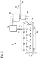
- is a plan view of a breezy/air drying device used in this invention;
- FIGS.4A and 4B
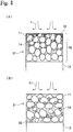
- are views illustrating the drying of the coated compound mixture by hot air flow and by breezy/air, respectively;
- FIGS.5A and 5B
- are plan views showing different battery structures;
- FIGS.6A and 6B
- are plan views showing different structures of electric double-layer capacitors;
- FIGS. 7A to 7C
- are plan views showing different levels of peeling strength.
- FIG. 8
- is a schematic view illustrating the covering of ion-conducting polymer;
- FIGS. 9A to 9D
- are, plan, perspective and cross-sectional views of the respective press-sliding and kneading device;
- FIG. 10
- is a plan view of a fixing or adhesion device; and
- Fig. 11
- is a schematic view of a prior art hot air heating device.
- The embodiments of the invention are next described while referring to the accompanying drawings.
- The electrode structure of this invention can be used in the electrodes of electronic components wherein typically an electrolyte is provided between the electrodes. When the electrical component is a battery, the electrode structure exchanges electricity by way of electrolyte ions. When the electrical component is a double-layer capacitor, the electrode structure forms an electrical double-layer between a material with a large surface area and electrolyte.
- Figure 1 illustrates examples of typical electrode structures. The electrode structure of FIG. 1(A) is used as the positive electrode of a battery. In this figure, the
electrode structure 1 is anelectrode film 18 consisting of an electrode active material as anelectrode material 11, an electrically-conductive material 14, andbinder 17, attached to the surface of the current-collectingmember 13. Here, LiCoO2, i.e., the powdered electrode active substance, for example, is used as the electrode active material. - In FIG. 1(B), an ion-conducting
polymer 12 is attached to the poweredelectrode material 11 of FIG. 1(A). The ion-conductingpolymer 12 also acts as a binder. FIG. 1(C) shows an electrode structure used in the negative electrode of a battery. In this figure, theelectrode structure 1 is anelectrode film 18 consisting of a powdered electrode active substance as anelectrode material 11 and abinder 17, attached to the surface of the current-collectingmember 13. Here, graphite powder is, for example, used as the powdered electrode active substance. - FIG. 1(D) is the electrode material of FIG. 1(C) coated with the ion-conducting
polymer 12. This ion-conducting polymer also functions as a binder. In FIG. 1(E), the electrode structure is used as an electrode for the double-layer capacitor. In this figure, theelectrode structure 1 is anelectrode film 18 consisting of a large surface area material as anelectrode material 11 and abinder 17, attached to the surface of the current-collectingmember 13. - Here, active carbon material, i.e., powdery high surface area material, is used, for example, as the large surface area material.
- In FIG. 1(F), an ion-conducting
polymer 12 is attached to the powdery high surface area material of FIG. 1(E). This ion-conducting polymer also functions as a binder. When theelectrode material 11 is covered with the ion-conductingpolymer 12, this ion-conducting polymer functions as a binder. The electrode material covered with the ion-conducting polymer is described in detail later on. - An example of the manufacturing method of this invention to produce an electrode structure is shown in FIG. 2. The
electrode material 11, electrically-conductive material 14,binder 17, andsolvent 19 are mixed together by slurrying in amixer 3 to obtain the mixedmaterial 31. The mixedmaterial 31 is lightly coated onto the surface of the current-collectingmember 13. - The method for coating the
mixed material 31 may proceeded by a doctor knife applicator. The solvent of the mixed material coating is vaporized by breezy/air heating, and the material coating dried and attached to the current-collectingmember 13 as theelectrode film 18. As such, this invention provides the same advantages as an electrode film obtained through the method of drying the mixed material coating by infrared radiation as disclosed in Japanese Patent Application No. 2000-32279 by the present inventors. - Breezy/Air heating is a heating method for drying the
mixed material 31 and is conducted by directing breezy/air with heat, i.e.,warm breeze 51, to themixed material 31. A breezy/air heater 51 is a device used to heat an object by blowing air, wherein the breezy/air with heat, i.e., thewarm breeze 51, is directed onto the mixed material to dry the mixed material intoelectrode film 18. - For example as in FIG. 3, the breezy/air is injected from an
outside air inlet 59, dried by adry air generator 58, and heated by anair heater 52, and thewarm breeze 51 is injected into thecabinet 56 via aguide tube 53. Theelectrode film 18 coated on the current-collectingmember 13 is moved within thecabinet 56 by a conveying means such as aconveyer 55. Thewarm breeze 51 is directed onto theelectrode film 18, vaporizes the solvent involved in theelectrode film 18, and is subsequently directed into thesolvent collector 57 viaducts 54, thereby collecting the vaporized solvent. - The
warm breeze 51 after removing the solvent is exhausted frompartial ducts 60, and the rest of the air is returned into thedry air generator 58. Thewarm breeze 51 in this invention preferably is a gas flow such as an air flow of 60-150 °C at 0.1-3m/second or lower. - When
warm breeze 51 is used, theelectrode film 18 from the dried mixed material adheres (or bonds) well to the current-collectingmember 13, and the electrical resistance of theelectrode film 18 is also low. The reason for the above result may be shown in a hypothetical process as depicted in FIG. 4. FIG. 4 shows an enhanced view of the internal state of themixed material 31 when the solvent 19 of the mixed material coated on the current-collectingmember 13 is vaporized. FIG. 4(A) shows the conventional method of applying hot air flow f of 80-200 °C at 15-25 m/second onto themixed material 31 to vaporize the solvent 32 mixed with a binder. FIG. 4(B) shows the method of this invention wherein thewarm breeze 51 of 60-150 °C at 1-3m/second, is directed onto themixed material 31 to vaporize the solvent 32 mixed with a binder. - The solvent vaporization process works as follows in the case of the conventional method of directing the hot air flow f of FIG. 4(A). First, when hot air flow f is applied to the surface of the mixed material, the area around the surface of the
mixed material 31 suddenly warms up in the hot air flow f, and the solvent on the surface is vaporized and blown away by the hot air flow f. - The solvent near the surface therefore quickly vaporizes, and to compensate, the solvent at the interior of the mixed material and near the collector electrode moves to the vicinity of the surface The binder contained in the solvent and the powdered conducting material are at this time carried to the surface of the
mixed material 31 along with the solvent. That is, migration of the binder and the powdered conducting material occurs. - As a result, the binder concentration of the mixed material in the vicinity of the current-collecting
member 13 and the powdered conducting material concentration become thin. The electrode film therefore tends to easily peel away from the current-collectingmember 13; the relative electrical resistance in the vicinity of the current-collecting member becomes high; and the resistance of the electrode overall becomes high. - In contrast, in the method of this invention shown in FIG. 4(B) in which the
warm breeze 51 is directed, the solvent vaporization process works as follows. When thewarm breeze 51 is directed onto the mixed material surface, thewarm breeze 51 gradually heats up the entire mixed material and gradually vaporizes the solvent from the mixed material surface. The concentrations of binder and powdered conductingmaterial 14 therefore remain uniform overall. That is, migration of the binder and the powdered conducting material is prevented. - As a result, the binder concentration in the vicinity of the current-collecting
member 13 does not become weak (or thin) in the electrode material of driedmixed material 31. Accordingly, the electrode film adheres well to the current-collectingmember 13. Further, the concentration of the powdered conducting material in the vicinity of the current-collectingmember 13 does not become weak either, so that the electrical resistance of the overall electrode film is low. - The current-collecting
member 13 may be any material capable of conducting electricity, and the material and shape can be selected according to the electroniccomponent containing member 13. As one example, the electrically-conductive material may be aluminum or copper and formed into a plate, leaf or mesh shape. When the current-collecting member is a plate or leaf shape, one or both sides are used according to the structure of the electronic component. - The
electrode film 18 for adhering to the current-collectingmember 13 may be pressed into the current-collecting member to make it further adhere. To further fixfilm 18, a fixing device 4 as shown in Fig. 10 is used. Anelectrode structure 1 made from current-collecting member coated with mixed material is enclosed by thepressure rollers 41. Electrode film can be bonded to the current-collecting member by applying a rotating pressure with thepressure device 43 and by means of thebackroller 42 applied againstpressure rollers 41. Further, the fixing or adhesion device 4 is not limited to a four-roller device and is sufficient as long as it presses and adheres the electrode film to the current-collecting member . For example, a two-roller press device may be appropriate. - The electrode structure of FIG. 1(A) or FIG. 1(B) can be used as the positive electrode while an electrode structure useful as a negative electrode is shown in FIG. 1(C) or FIG. 1(D). An electrolyte may be positioned between the respective electrode structures. FIG. 5 shows an example in which a battery comprises an electrode structure of FIG. 1(B) as the positive electrode and an electrode structure of FIG. 1(D) as the negative electrode.
- Here, FIG. 5(A) shows the case when the electrolyte is a
liquid electrolyte 16, and aseparator 15 is placed between the electrodes. FIG. 5(B) shows the case when the electrolyte is an ion-conductingpolymer 12 in solid. Theseparator 15 is installed to isolate one pair ofelectrode structures 1, and the electrolyte can be used in solid when required according to circumstances. - The double-layer capacitor has a structure with electrolyte placed between one pair of electrodes of the electrode structure of FIG. 1(E) or one pair of electrodes of the electrode structure of FIG. 1(F). A double-layer capacitor utilizing the electrode structure of FIG. 1(E) is shown in FIG. 6(A), and a double-layer capacitor utilizing the electrode structure of FIG. 1(F) is shown in FIG. 6(B).
- Here, FIG. 6(A) shows the case when the electrolyte is a
liquid electrolyte 16, and aseparator 15 is placed between the electrodes. FIG. 6(B) shows the case when the electrolyte is an ion-conductingpolymer 12 in solid. Theseparator 15 is installed to isolate one pair ofelectrode structures 1, and the electrolyte can be used in solid when required according to circumstances. - Examples of the electrode structure are described next.
- Eight electrode structure sample pieces 1 - 8 were dried using two types of heating methods; one method was the hot air flow method of the prior art and the other was breezing/air heating method of this invention. The peeling strength and impedance (Ω/ohm) of these sample pieces were measured. A battery using the electrode structures was prepared and a cycle degradation was measured. The ratio (proportions) of electrode material, conductive material, binder, and solvent material used in the preparation of the sample pieces are shown in Table 1.
ACTUAL ELECTRODE COMPOSITION (per weight) Sample Active carbon; material or LiCoO2 Powder conducting material (carbon black) Binders Thickness of electrode Solvent (per weight) Polymer A1 Polymer A2 Teflon PVDF 1 20 0 0.8 0.24 350 NMP (30) 2 20 0 1 75 NMP (30) 3 20 0 1 50 NMP (30) 4 20 0 1 75 NMP (30) 5 18 2 1 350 NMP (30) 6 18 2 1 350 NMP (30) (LiCoO2) 7 91 6 3 85 NEK(20) + NMP (10) 8 91 9 11 92 NMP (20) -
Samples 1 through 6 represent electrodes useful for capacitors. The electrode material was made from phenol active carbon (made by Kansai Chemical Corp.) which was dry mixed with carbon black, i.e., the powdered conductive material, as the conductive material, utilizing a mixer. Samples 7 through 8 represent positive electrodes for batteries. Carbon black of the powdered conductive material as the electrode was added to LiCoO2 of the powdered electrode active substance which served as the electrically-conductive material by dry type mixing performed utilizing a mixer. The binder was then added to all thesamples 1 through 8 and mixing performed. A specified amount of solvent was further added and mixing was performed. After mixing, the material was coated onto the collector element with a doctor knife applicator. The samples were then dried by breezy/air heating or conventional hot air heating. - The
samples 1 to 6 utilized active carbon material as the electrode material. Sample 7 utilized LiCoO2 as the electrode material and PVDF (polyvinylidene fluoride) as the binder.Sample 8 utilized LiCoO2 as the electrode material and polymer A2 as the binder, and was covered with ion-conducting polymer.Samples 1 through 4 contained no carbon black powdered electrically-conducting substance, andsamples 5 through 11 contained carbon black though there were differences in the concentrations used in the samples. Polymer A1, polymer A2, Teflon powder, and PVDF were used as the binders. Polymer A1 and polymer A2 were ion-conducting polymers. The raw materials used to form polymers A1 and A2 are shown in Table 2 and Table 3, respectively. NMP (N methyl-2-pyrrolidone) was mainly used as the solvent, and MEK (methyl ethyl ketone) was used only in preparing sample 7.Substance Mixing ratio (weight parts) Tri-functional (propylene glycol/ethylene glycol) random copolymer, SANNIX FA-103 (PO/EO=2/8, Mw=3,282, Sanyo Chemical Industries, Ltd.) 8.36 Difunctional 1, 4-butanediol0.34 Ethylene cyanohydrin 1.27 Reaction catalyst NC-IM (Sankyo Air Products K.K.) 0.03 Total 10 Substance Mixing ratio (weight parts) Cyanoethylated/dihydroxypropylated polyvinyl alcohol 0.625 Methoxypolyethyleneglycol methacrylate (mol. wt. 468) 3.125 Trimethylolpropanetrimethacrylate (mol. wt. 536) 6.25 Total 10 - With respect to breezy/air heating of this invention, the
air heater 52, the ancillarydry air generator 58, and thesolvent collector 57 are driven to generate dry air. The warm breeze is supplied into thecabinet 56 at 1 m/second (approximately minimum of 0.5-maximum 1.5 m/second) An area within thecabinet 56 wherein the warm breeze is flown through is divided into a first zone keeping the warm breeze approximately at 80 °C and a second zone keeping the warm breeze approximately at 100 °C. The sample material is supplied into the first zone then into the second zone at 3 m/minute. Length of the first and second zones each is approximately 4.5 m (total of 9 m), the time required for the air to flow though is approximately 3 minutes, and the mixed material is dried for 3 minutes. As such, the mixed material was dried so that migration of the binder and the powdered conducting material may be prevented. - A device as shown in FIG. 11 was utilized for the hot air heating, where outside air within a room is drawn from outside of the device. The hot air flow had a 60 % relative humidity and was directed at the sample at 15m/second for 3 minutes to dry the mixed material. The same procedure as in breezy/air heating was performed except for the wind velocity and drying of the hot air flow. For a reference purpose, the hot air flow of dried outside air as in this invention was also tested. That is, all the same steps in the above hot air flow heating are used except for the dry air instead of outside air (having 60 % relative humidity).
- To measure the peeling strength, cellophane tape (
KOKUYO TSS18N width 18 mm, thickness 50 µm) was attached to the electrode film fabricated on the surface of the current-collecting member, and the cellophane tape was then pulled away to make the electrode film stuck onto the cellophane tape separate from the current-collecting member. A peeling strength ranking could then be established according to the tape separate from the current-collecting member. A peeling strength ranking could then be established according to the amount of electrode film peeled from the surface of the current-collecting member. - FIG. 7 taken from photographs shows the electrode film stuck to the cellophane tape. FIG. 7(A) taken from photographs shows a small flaked portion of the upper electrode film, which is ranked a. (The blacken portion in the photograph is the flaked portion of the electrode film.) FIG. 7(B) taken from photographs shows a small flaked portion of the middle electrode film, which is ranked b. (The blacken portion in the photograph is the flaked portion of the electrode film.)
- FIG. 7(C) taken from photographs shows an electrode film completely peeled from the current-collecting member, which is ranked c. (The blacken portion in the photograph is the flaked portion of the electrode film.) For samples measurement, the results of peeling strength and impedance (Ω/ohm) are shown in Table 4.
Sample Dry breezy/air heating Hot outside air heating Hot dry air heating Peeling Strength Impedance (Ω/ohm) Peeling Strength Impedance (Ω/ohm) Peeling Strength Impedance (Ω/ohm) 1 a 2.5 c 96 - - 2 a 0.7 b 36 - - 3 a 0.9 b 8.6 - - 4 b 0.5 c 1.8 - - 5 a 0.3 b 1.11 - - 6 a 0.7 c 1.35 - - 7 b 2.3 c 6 c 5 8 a 0.5 b 3 b 3 - To measure the impedance (Ω/ohm), the electrodes formed on the collector element were enclosed by copper plates of 2 centimeters in diameter and 5 millimeters thick. A pressure of 4.5 kilograms per centimeter was applied from above and below, and the resistance at 10 kilohertz AC was measured with an impedance analyzer.
- On comparing dry breezy/air heated samples and outside hot air heated and dry hot air heated samples having the same sample numbers, in all cases, the peeling strength for the dry breezy/air heating samples was found to be one or two ranks higher than the hot air heated samples. In the impedance test results also, the breezy/air heated samples had an impedance (Ω/ohm) which was small, indicating low resistance. Further, comparing the outside hot air heating with dry hot air heating only as to the
samples 7 and 8, there does not exist large differences regarding the peeling strength and impedance (Ω/ohm) between the two. - An electrode prepared according to the above-embodiment was used to prepare a battery, and Table 5 shows comparison results of dry breezy/air heating, outside hot air heating, and dry hot air heating. A lithium ion battery was prepared by combining the positive electrode using LiCoO2 obtained through breezy/air heating and hot air heating (including outside air and dry air) of sample 7 as an active material and a negative electrode using graphite as an active material, which was used as test samples. Charging and discharging were performed using the test samples.
- As this negative electrode, using a normal blade mixer, 9.5 weight part of powdered graphite with average particle size of 4 µm, i.e., powdery electrode active material, was mixed with 25.5 weight part of n-methylpyrrolidone having 0.5 weight part of dissolved polyvinylidene fluoride (PVDF) without ion conductive polymer, as the macromolecular binder.
- After mixing about 8 hours, the mixed material was taken out and was placed on a copper foil of 20 µm in thickness and was cast using a doctor knife applicator with gap of 100 µm. Then, breezy/air drying with the dry air of this invention was conducted to vaporize n-methylpyrrolidone. The electrode thus obtained had a thickness of 80 µm. The battery had a separator between the positive electrode having an electrode film of 0.94 cm2 on one surface and the negative electrode having an electrode film of 0.94 cm2 on one surface in order to prepare a coincell. Electrolyte was filled up to prepare a test cell. EC/DEC(1/1)V/V solution dissolving 1.0 M of LiPF6 was used as electrolyte.
- The result of cycle degradation is shown in Table 5. The amount of charging and discharging at the first cycle (time) was assumed to be 100 and which will be compared with the amount at 200 cycles and 400 cycles. Conducting breezy/air heating accordingly was found to produce an electrode with less degradation as shown in Table 5. Further, comparing the outside air heating with dry hot air heating, the amount of charging and discharging at 200 cycles and 400 cycles regarding the dry hot air heating showed better results so far as the cycle degradation is concerned.
Condition of drying Positive electrode No. Discharging ratio at 200 cycles Discharging ratio at 400 cycles Breezy/air drying of dry air 7 96 94 Hot air drying of outside air 7 86 80 Hot air drying of dry air 7 91 87 - When air with relatively higher humidity is heated to prepare an electrode, electrode materials within the electrode sometime absorb moisture. Especially for a battery and an electrical double-layer capacitor used with high voltage (i.e., 1.5 V or more), a trace of moisture absorbed may cause electrolysis within the electrode to generate hydrogen and oxygen. As a result of the above
- Also, with respect to a lithium type battery, LIPF6 and LiBF4 may be used as the ion conductive salt. Since these materials react with a trace of moisture and generate HF, HF generated corrodes a wide variety of materials to cause cycle degradation. Accordingly, zero temperature of air as dry air should be -10 °C or lower, preferably -20 °C or lower, more preferably -40 °C or lower and most preferably -50 °C or lower.
- Here, the condition for charging should be such that charging is first conducted at a charging current of 0.21-0.26 mA/cm2, secondly, maintaining a charging voltage of 4.2 V for two hours upon reaching 4.2 V, and thirdly, pausing the charging for ten minutes. The condition for discharging should be such that discharging is conducted at a discharging current of 0.21-0.26 mA/cm2 up to 2.7 V of final voltage and pausing the discharging for ten minutes. Charging and discharging are repeated under room temperature.
- The electrode material coated with ion-conducting polymer is described next.
- In FIG. 1, the powdered electrode
active substance 11 has the shape of particles consisting of bonded particles like LiCoO2. The process for depositing the ion-conductingpolymer 12 is also shown. Here, "adhere" or "adhesion" means that ions are attached in such manner that the ions can migrate between the ionconductive polymer 12 and the entire surface of the powdery electrode material. It means that the ionconductive polymer 12 adheres to the surface of thepowdery electrode material 11 and covers it with the ionconductive polymer 12. - The finer the particles are, the more active the powdery electrode
active material 11 is. When it is adhered to and covered by the ionconductive polymer 12, the activity is suppressed and can be turned a to more stable state. When the deposit of ion-conductingpolymer 12 is thick, the electrical conduction decreases, and the current (charge) collection is poor. - Accordingly, forming a thin coating of ion-conducting polymer is preferable. Inventions relating to electrode structures coated with ion-conducting polymer have already been proposed by the applicants of this invention (Japanese Patent Application 11-262501, and Japanese Patent Application 11-262502).
- The powder shape such as for the powdered electrode
active substance 11 and powdered conductingmaterial 14 is a fine particle substance. Further, such a powder is a collection of many substances. In certain cases, this fine particle substance refers to a state wherein a large number of substances in a fine particle state constitute an agglomeration. - The powdered electrode active substance uses ion insertable-separable materials and π-conjugated conductive macromolecular materials. For example, there are no particular restrictions on the electrode active substance used as the positive electrode for non-aqueous electrolyte batteries. However, in the case of chargeable batteries, chalcogen compounds allowing ion insertion/separation or composite chalcogen compounds containing lithium are recommended.
- FeS2, TiS2, MoS2, V2O5, V6O13, and MnO2 may be employed as the above-chalcogen compounds. The chalcogen compound having lithium as described above includes LiCoO2, LixNiyM1-yO2 (where M represents at least one type of metal element selected from transition metal or aluminum, or more preferably, it represents at least one type of metal element selected from Co, Mn, Ti, Cr, V, or Al, and 0.05 ≦ x ≦1.10 and 0.5 ≦ y ≦ 1.0), LiNiO2, LiMnO2, LiMn2O4, etc. Using oxide, salt or hydroxide of lithium, cobalt, nickel or manganese as starting materials, these starting materials are mixed in adequate composition, and the mixture is fired in the temperature range of 600 °C - 1000 °C under oxygen atmosphere.
- There are no particular restrictions on the electrode active substance used as the negative electrode for non-aqueous electrolyte batteries. However, a material allowing lithium ion insertion/separation may be used, and lithium metal, lithium alloys (alloys such as lithium and aluminum, lead, indium) and carbon quality materials may be utilized.
- Polyacetylene types, polyaniline types, polypyrrole types, polythiophene types, poly-ρ(para)-phenylene types, polycarbazole types, polyacene types and sulfur polymer types are among the useful π-conjugated conductive macromolecular materials.
- Using lithium metals in the negative electrode achieves a large battery capacity particularly in primary non-aqueous electrolyte batteries.
- Also, in non-aqueous electrolyte batteries, using carbon materials in the negative electrodes, that are capable of lithium ion insertion/separation yields a longer battery cycle life span. There are no particular restrictions on the carbon material used but materials such as pyrolytic carbon types, coke types (pitch coke, needle coke and petroleum coke, etc.) graphite types, glass carbon types, organic macromolecular compound fired products (carbonized pieces baked to a suitable temperature such as phenol resin and furan resin) carbon fibers and active carbon may be utilized.
- The powdered electrically-conducting substance raises the conductivity of the electrode structure and though there are no particular restrictions, materials such as metal powder and carbon powder may be used. Particularly, preferred carbon powders are pyrolytic carbons such as carbon black, and their graphite products, artificial and natural scaly graphite powder, carbon fibers and their graphite products, etc. Product mixtures of these carbon powders are also utilized.
- The ion conductive polymer is a polymer, which can dissolve at least an ion conductive salt such as lithium salt at concentration of 0.1 M (mol/l) or more shows an electrical conductivity of 10-8 S (Siemens)/cm or more at room temperature. Preferably, it is an ion conductive polymer, which dissolves at least ion conductive salt such as lithium salt and exhibits electrical conductivity of 10-2 S/cm - 10-5 S/cm at room temperature.
- The lithium salt is at least one type of lithium salt having ClO4 -, CF3SO3 -, BF4 -, PF6 -, AsF6 -, SbF6 -, CF3CO2 - or (CF3SO2)2N- as anion.
- The ion-conducting polymer raw material is a substance which produces the ion-conducting polymer by polymerizing, crosslinking, etc., when energy is supplied externally. Also, the raw material itself may be a polymer. The energy may be heat, ultraviolet light, light or electron radiation.
- The method of manufacturing these electrode structures will now be described.
- The method of coating the powdered conductive material with the ion-conducting polymer as is shown in Fig. 8 is to press-slide the ion-conducting polymer and the powdered electrode active substance against each other. In this process, by using only a minute amount of the ion-conducting polymer, the particle surfaces of the powdered electrode active substance are coated with the ion-conducting polymer, no voids are formed, and gaps in the powdered substance are reduced.
- Press-sliding is the action of sliding while pressing
mixtures 10 of the ion-conductingpolymer 12 or the raw material of the ion-conductingpolymer 12 and thepowdered substance 11 together. An external force is applied to the mixtures so that they cohere to each other and the particles rotate, and this process is performed repeatedly to obtain a press-sliding product. - The press-sliding and kneading mixer is shown, for example, in Fig. 9(A). The
mixture 10 of the ionconductive polymer 12 and thepowdered material 11, or a mixture containing this mixture and amixture 10 containing solvent, is placed in acontainer 21, and amain blade 22 is rotated. There is a gap between a bottom 211 of thecontainer 21 and themain blade 22. When themain blade 22 is rotated, a part of themixture 10 is moved between the bottom 211 of thecontainer 21 and themain blade 22. It is subject to press-sliding and kneading. This process is repeated to coat the ion-conductingpolymer 12 on thepowdered substance 11. A press-slidingmixer 2 may if necessary be provided with adispersion blade 23 in thecontainer 21. Thedispersion blade 23 is rotated at high speed viamotor 231 to disperse the press-slide mixture 10. - The
container 21 is provided for holding themixture 10 which is press-slid and stirred. At the bottom of thecontainer 21, there is provided alower portion 2111 with a part of it at lower position. The bottom surface is inclined upward as it goes toward the peripheral portion ofcontainer 21. For instance, the bottom surface is lower at the center, and gradually goes up toward the periphery. - The bottom 211 is formed in the shape of a conical mortar. The inclination angle of the
lower portion 2111 is set to 150 °C, for example. Thebottom 211 of the container is wear-resistant, and can be formed by thermal spraying with tungsten or carbide using SUS. Plural bottom parts of this type may also be formed on thebottom surface 2111. - The
main blade 22 functions together with thebottom surface 211 of thecontainer 21, serving to press-slide and stir themixture 10. Themain blade 22, is positioned viashaft 221 to the desired location relative to thebottom 211 of thecontainer 21 as shown for example in Figs. 9(A) and 9(B). Themain blade 22 curves upwards corresponding to the slant ofbottom 211 of thecontainer 21. Themain blade 22 may comprise two blades attached from the center part as shown in Fig. 9(B), or it may comprise a larger number of blades, e.g. 10 or more, depending on the amount and type of mixture. - The number of rotations of a
main motor 222 driving themain shaft 221 is set low for example to 120 rpm or less, when press-sliding is performed. - The gap between the
bottom surface 211 of thecontainer 21 and the base surface of themain blade 22 is set as narrow as is necessary for press-sliding the mixture, for example 15 mm or less. This distance depends on the capacity of the press-slidingmixer 2 and on the shape of the main blade, etc. - The surface in the motion direction (press-sliding direction) of the
main blade 22 is formed so that a pressing angle relative to the bottom surface of thecontainer 21 is an acute angle. For example, if the cross-section of themain blade 22 is a reverse trapezoid as shown in Fig. 9(C), the pressing angle is from 3-70 degrees. The cross-section of themain blade 22 may also be circular or have a rounded corner as shown in Fig. 9(D). The material of the main blade has wear-resistant properties, and is formed for example by thermal spraying with tungsten or carbide using SUS. - The surface of the
main blade 22 opposite to the advancing direction (direction of pressurizing and grinding) is designed in such manner that it runs almost perpendicularly to the bottom surface and at acute angle. As a result, when themain shaft 221 is rotated in reverse direction, themixture 10 can be collected on the periphery of themain shaft 221. - If there are plural bottom parts on the
bottom surface 211, the center parts of themain blade 22 are also disposed in positions of the bottom part corresponding to their number. - The
dispersion blade 23 disperses themixture 10 which is press-slid by themain blade 22. Thedispersion blade 23 is disposed in a position at which themixture 10 can be dispersed, and it rotates at a high speed such as 1000-4000 rpm. Due to this high speed rotation, the ion-conductingpolymer 12 or its raw material coated on the particle surfaces of the powderedsubstance 11 uniformly disperses through the whole of the powdered substance. - This invention as described above, renders the following effects.
- An electrode film that adheres well to the current-collecting member can be obtained.
- An electrode film with low electrical resistance can be obtained.
- A battery or double-layer capacitor with an electrode film having low electrical resistance and good bonding can be obtained.
- It is readily apparent that the above-described invention has the advantages of wide commercial utility. It may be understood that the specific form of the invention hereinabove described is intended to be representative only, and certain modifications within the scope of these teachings will be apparent to those skilled in the art without departing from the spirit and scope of the invention.
- Accordingly, reference should be made to the following claims in determining the full scope of the invention.
Claims (8)
- A method of manufacturing an electrode structure (1) by coating a compound mixture (31) comprising an electrode material (11), a binder (17), and a solvent (19) onto a current-collecting member (13), directing a warm breeze (51) onto the compound mixture (31) coating to gradually vaporize the solvent (19, 32) and to form an electrode film (18) on the current-collecting member (13).
- The method according to claim 1,
wherein the mixture (31) contains a material capable of conducting electricity (conductive material) (14). - A method of manufacturing a battery with electrode structures (1) used as electrodes of the battery, wherein a compound mixture (31) comprising an electrode active material (11), a conductive material (14), a binder (17), and a solvent (19) is coated onto a current-collecting member (13), and wherein a warm breeze (51) is directed onto the coating of the mixed material (31) to vaporize the solvent (19, 32) and to form an electrode film (18) on the current-collecting member (13) to constitute the electrode structures (1).
- A method of manufacturing a battery with electrode structures (1) as battery electrodes,
wherein a compound mixture (31) comprising a powered electrode active substance (11) coated with an ion-conducting polymer (12), a powdered electrically-conducting substance (14), and a solvent (19) is coated onto a current-collecting member (13), and wherein a warm breeze (51) is directed onto the coating of mixed material (31) to vaporize the solvent (19, 32) and to form an electrode film (18) on the current-collecting member (13) to constitute the electrode structures (1). - A method of manufacturing an electrical double-layer capacitor with electrode structures (1) as electrodes, wherein a compound mixture (31) comprising a large surface area material (11), a binder (17) and a solvent (19) is coated onto a current-collecting member (13), and wherein a warm breeze (51) is directed onto the coating of mixed material (31) to vaporize the solvent (19, 32) and to form an electrode film (18) on the current-collecting member (13) to constitute the electrode structures (1).
- A method of manufacturing a double-layer capacitor with electrode structures (1) as electrodes,
wherein a compound mixture (31) comprising a large surface area material (11) coated with an ion-conducting polymer (12), a powdered electrically-conducting substance (14), and a solvent (19) is coated onto a current-collecting member (13), and wherein a warm breeze (51) is directed onto the coating of the mixed material (31) to vaporize the solvent (19, 32) and to form an electrode film (18) on the current-collecting member (13) to constitute the electrode structures (1). - The method according to any of claims 1 to 6,
wherein a warm breeze (51) in a temperature range of about 60 °C to 150 °C is used and is directed onto the compound mixture (31) at a speed of about 0.1 to 3 m/s. - The method according to any of claims 1 to 7,
wherein a dry breeze (58, 52, 53, 51) is used as the warm breeze (51) which is directed onto the compound mixture (31).
Applications Claiming Priority (2)
| Application Number | Priority Date | Filing Date | Title |
|---|---|---|---|
| JP2000164947 | 2000-06-01 | ||
| JP2000164947A JP2001345095A (en) | 2000-06-01 | 2000-06-01 | Fabricating method of electrode structure, cell and electric double layer capacitor |
Publications (2)
| Publication Number | Publication Date |
|---|---|
| EP1160896A2 true EP1160896A2 (en) | 2001-12-05 |
| EP1160896A3 EP1160896A3 (en) | 2004-04-07 |
Family
ID=18668495
Family Applications (1)
| Application Number | Title | Priority Date | Filing Date |
|---|---|---|---|
| EP01113010A Withdrawn EP1160896A3 (en) | 2000-06-01 | 2001-05-28 | Electrode structure, battery and electrical double-layer capacitor and method of manufacturing same |
Country Status (8)
| Country | Link |
|---|---|
| US (1) | US20020069514A1 (en) |
| EP (1) | EP1160896A3 (en) |
| JP (1) | JP2001345095A (en) |
| KR (1) | KR20010109216A (en) |
| CN (1) | CN1252845C (en) |
| CA (1) | CA2348858A1 (en) |
| SG (1) | SG101975A1 (en) |
| TW (1) | TW510065B (en) |
Cited By (2)
| Publication number | Priority date | Publication date | Assignee | Title |
|---|---|---|---|---|
| EP1241720A3 (en) * | 2001-03-15 | 2004-10-20 | Wilson Greatbatch Ltd. | Process for fabricating continuously coated electrodes on a porous current collector and cell designs incorporating said electrodes |
| WO2005119717A1 (en) * | 2004-06-03 | 2005-12-15 | Epcos Ag | Method for producing electrodes for passive components and batteries, and device for producing electrodes |
Families Citing this family (13)
| Publication number | Priority date | Publication date | Assignee | Title |
|---|---|---|---|---|
| US20050175890A1 (en) * | 2000-10-31 | 2005-08-11 | Kazuo Tsutsumi | Battery |
| JP4276063B2 (en) * | 2003-12-26 | 2009-06-10 | Tdk株式会社 | Electrode capacitor electrode manufacturing method and electrochemical capacitor manufacturing method |
| JPWO2005117043A1 (en) * | 2004-05-27 | 2008-04-03 | 日本ゼオン株式会社 | Electrode device electrode manufacturing method and apparatus |
| JP4571841B2 (en) * | 2004-09-30 | 2010-10-27 | 大日本印刷株式会社 | Electrode plate manufacturing method |
| EP1657730A3 (en) | 2004-11-15 | 2007-05-30 | Mitsubishi Gas Chemical Company, Inc. | Electrode sheet and electric double layer capacitor using the same |
| JP2012146852A (en) * | 2011-01-13 | 2012-08-02 | Tokyo Electron Ltd | Electrode manufacturing device, electrode manufacturing method, program, and computer storage medium |
| JP2013134909A (en) * | 2011-12-27 | 2013-07-08 | Toray Eng Co Ltd | Drying method for coating of collector electrode |
| WO2013153603A1 (en) * | 2012-04-09 | 2013-10-17 | 株式会社日本マイクロニクス | Secondary battery |
| JP6003560B2 (en) * | 2012-11-15 | 2016-10-05 | 株式会社豊田自動織機 | Electrode manufacturing method |
| JP6003559B2 (en) * | 2012-11-15 | 2016-10-05 | 株式会社豊田自動織機 | Electrode manufacturing method |
| JP6858663B2 (en) * | 2017-07-26 | 2021-04-14 | 旭化成株式会社 | Constant temperature bath for power storage devices |
| CN112055909A (en) | 2018-05-03 | 2020-12-08 | 株式会社Lg化学 | Method for manufacturing all-solid-state battery including polymer solid electrolyte and all-solid-state battery obtained by the method |
| CN114229920B (en) * | 2021-12-20 | 2024-01-26 | 蜂巢能源科技股份有限公司 | Positive electrode material, preparation method thereof, positive electrode plate and battery |
Citations (5)
| Publication number | Priority date | Publication date | Assignee | Title |
|---|---|---|---|---|
| US4969254A (en) * | 1988-06-08 | 1990-11-13 | Moli Energy Limited | Electrochemical cells, electrodes and methods of manufacture |
| EP0633618A1 (en) * | 1992-12-25 | 1995-01-11 | TDK Corporation | Lithium secondary cell |
| US5426561A (en) * | 1992-09-29 | 1995-06-20 | The United States Of America As Represented By The United States National Aeronautics And Space Administration | High energy density and high power density ultracapacitors and supercapacitors |
| US5682928A (en) * | 1996-06-20 | 1997-11-04 | Entek Manufacturing Inc. | Method and apparatus for making battery plates |
| EP0814521A2 (en) * | 1996-06-17 | 1997-12-29 | Dai Nippon Printing Co., Ltd. | Process for producing porous coating layer, electrode plate for secondary battery with nonaqueous electrolyte, process for producing same and sheet for peeling active material layer |
Family Cites Families (16)
| Publication number | Priority date | Publication date | Assignee | Title |
|---|---|---|---|---|
| JPS6386350A (en) * | 1986-09-30 | 1988-04-16 | Shin Kobe Electric Mach Co Ltd | Manufacture of plate for sealed alkaline storage battery |
| JPH07130341A (en) * | 1993-11-02 | 1995-05-19 | Fuji Photo Film Co Ltd | Nonaqueous battery |
| JP3348513B2 (en) * | 1994-03-31 | 2002-11-20 | ソニー株式会社 | Polymer solid electrolyte battery |
| JPH08111222A (en) * | 1994-10-12 | 1996-04-30 | Fuji Photo Film Co Ltd | Manufacture of sheet-form electrode plate |
| JPH08227714A (en) * | 1995-02-21 | 1996-09-03 | Mitsubishi Pencil Co Ltd | Carbon material for negative electrode of lithium ion secondary battery and manufacture thereof |
| JPH09115504A (en) * | 1995-10-17 | 1997-05-02 | Nikkiso Co Ltd | Electrode for battery and its manufacture |
| JP3553244B2 (en) * | 1995-11-11 | 2004-08-11 | 大日本印刷株式会社 | Method for producing electrode plate for non-aqueous electrolyte secondary battery |
| US5945159A (en) * | 1996-12-12 | 1999-08-31 | Dcv, Inc. | Method for encapsulating very finely divided particles |
| US6127065A (en) * | 1997-04-25 | 2000-10-03 | Sony Corporation | Method of manufacturing cathode active material and nonaqueous electrolyte secondary battery |
| JPH1145716A (en) * | 1997-05-27 | 1999-02-16 | Tdk Corp | Manufacture of electrode for nonaqueous electrolytic battery |
| JPH11102696A (en) * | 1997-09-26 | 1999-04-13 | Sony Corp | Electrode manufacture device and its manufacture |
| JP3046790B2 (en) * | 1997-11-11 | 2000-05-29 | 東芝機械株式会社 | Apparatus and method for drying coating substrate |
| JP4095144B2 (en) * | 1997-12-09 | 2008-06-04 | Tdk株式会社 | Method for manufacturing battery electrode |
| JPH11339781A (en) * | 1998-05-28 | 1999-12-10 | Matsushita Electric Ind Co Ltd | Battery electrode plate, manufacture therefor and battery with the battery electrode plate |
| JP2000012004A (en) * | 1998-06-24 | 2000-01-14 | Toshiba Battery Co Ltd | Coating method for electrode active material and coating device for electrode active material |
| JP2000123839A (en) * | 1998-10-13 | 2000-04-28 | Toshiba Battery Co Ltd | Conductive agent applicator for sheet type current collector |
-
2000
- 2000-06-01 JP JP2000164947A patent/JP2001345095A/en active Pending
-
2001
- 2001-05-25 SG SG200103148A patent/SG101975A1/en unknown
- 2001-05-28 EP EP01113010A patent/EP1160896A3/en not_active Withdrawn
- 2001-05-29 CA CA002348858A patent/CA2348858A1/en not_active Abandoned
- 2001-05-30 CN CNB011161906A patent/CN1252845C/en not_active Expired - Fee Related
- 2001-05-30 TW TW090112989A patent/TW510065B/en not_active IP Right Cessation
- 2001-06-01 KR KR1020010030701A patent/KR20010109216A/en not_active Application Discontinuation
- 2001-06-01 US US09/870,771 patent/US20020069514A1/en not_active Abandoned
Patent Citations (5)
| Publication number | Priority date | Publication date | Assignee | Title |
|---|---|---|---|---|
| US4969254A (en) * | 1988-06-08 | 1990-11-13 | Moli Energy Limited | Electrochemical cells, electrodes and methods of manufacture |
| US5426561A (en) * | 1992-09-29 | 1995-06-20 | The United States Of America As Represented By The United States National Aeronautics And Space Administration | High energy density and high power density ultracapacitors and supercapacitors |
| EP0633618A1 (en) * | 1992-12-25 | 1995-01-11 | TDK Corporation | Lithium secondary cell |
| EP0814521A2 (en) * | 1996-06-17 | 1997-12-29 | Dai Nippon Printing Co., Ltd. | Process for producing porous coating layer, electrode plate for secondary battery with nonaqueous electrolyte, process for producing same and sheet for peeling active material layer |
| US5682928A (en) * | 1996-06-20 | 1997-11-04 | Entek Manufacturing Inc. | Method and apparatus for making battery plates |
Cited By (2)
| Publication number | Priority date | Publication date | Assignee | Title |
|---|---|---|---|---|
| EP1241720A3 (en) * | 2001-03-15 | 2004-10-20 | Wilson Greatbatch Ltd. | Process for fabricating continuously coated electrodes on a porous current collector and cell designs incorporating said electrodes |
| WO2005119717A1 (en) * | 2004-06-03 | 2005-12-15 | Epcos Ag | Method for producing electrodes for passive components and batteries, and device for producing electrodes |
Also Published As
| Publication number | Publication date |
|---|---|
| US20020069514A1 (en) | 2002-06-13 |
| KR20010109216A (en) | 2001-12-08 |
| EP1160896A3 (en) | 2004-04-07 |
| CA2348858A1 (en) | 2001-12-01 |
| JP2001345095A (en) | 2001-12-14 |
| TW510065B (en) | 2002-11-11 |
| CN1327274A (en) | 2001-12-19 |
| CN1252845C (en) | 2006-04-19 |
| SG101975A1 (en) | 2004-02-27 |
Similar Documents
| Publication | Publication Date | Title |
|---|---|---|
| US7397650B2 (en) | Electric double layer capacitor utilizing a multi-layer electrode structure and method for manufacturing the same | |
| EP1160896A2 (en) | Electrode structure, battery and electrical double-layer capacitor and method of manufacturing same | |
| US6234225B1 (en) | Cell electrode with thick tip portion | |
| CN1251347C (en) | Solid polymer elecrolytes | |
| US20140099538A1 (en) | Solid-State Battery Electrodes | |
| JP3652769B2 (en) | Electrode plate for non-aqueous electrolyte secondary battery | |
| JP2001307716A (en) | Multilayer electrode structure, battery using the same, electrical double layer capacitor, and their manufacturing methods | |
| KR20050028863A (en) | Method for producing an electrochemical device | |
| US20070154813A1 (en) | Electrode Structure Secondary Cell and Electrode Double Layer Capacitor | |
| JP2001035495A (en) | Positive electrode paste composition for lithium secondary battery, positive electrode, and its manufacture | |
| CN108365164B (en) | Method for manufacturing battery | |
| KR20020067676A (en) | Multi-Layer Electrode Structure, Battery and Electric Double Layer Capacitor Using the Same, and Method of Fabricating Them | |
| US20040058239A1 (en) | Electrode structure, battery and electrical double-layer capacitor and method of manufacturing same | |
| JP4355970B2 (en) | Solid electrolyte battery and manufacturing method thereof | |
| KR20020042685A (en) | Electrode structure, and rolling machine for working electrode structure | |
| EP1130667A1 (en) | Press-slide kneader, method for coating with ionic-conductive polymer, and powdery material | |
| JP2003132877A (en) | Positive electrode method for manufacturing the same and solid electrolyte battery | |
| JP2006107753A (en) | Coating composition for cathode active substance layer, cathode plate for nonaqueous electrolyte solution secondary battery, and nonaqueous electrolyte solution secondary battery | |
| US20040234677A1 (en) | Mixer for coating an ion-conducting polymer on a powdered substance and method for coating the same | |
| CN101578676A (en) | Binder for capacitor electrode | |
| JP2003173780A (en) | Coating composition for anode, anode plate, and nonaqueous electrolyte solution secondary battery | |
| JP2005078963A (en) | Nonaqueous electrolyte secondary battery and its manufacturing method | |
| WO2022261332A1 (en) | Processes for making batteries comprising polymer matrix electrolytes | |
| JP2003151631A (en) | Method of manufacturing lithium ion polymer battery and lithium ion polymer battery obtained by this method | |
| JP2002157998A (en) | Method of manufacturing composite positive electrode for solid lithium secondary battery and solid lithium secondary battery using same |
Legal Events
| Date | Code | Title | Description |
|---|---|---|---|
| PUAI | Public reference made under article 153(3) epc to a published international application that has entered the european phase |
Free format text: ORIGINAL CODE: 0009012 |
|
| AK | Designated contracting states |
Kind code of ref document: A2 Designated state(s): AT BE CH CY DE DK ES FI FR GB GR IE IT LI LU MC NL PT SE TR |
|
| AX | Request for extension of the european patent |
Free format text: AL;LT;LV;MK;RO;SI |
|
| PUAL | Search report despatched |
Free format text: ORIGINAL CODE: 0009013 |
|
| AK | Designated contracting states |
Kind code of ref document: A3 Designated state(s): AT BE CH CY DE DK ES FI FR GB GR IE IT LI LU MC NL PT SE TR |
|
| AX | Request for extension of the european patent |
Extension state: AL LT LV MK RO SI |
|
| RIC1 | Information provided on ipc code assigned before grant |
Ipc: 7H 01G 9/00 B Ipc: 7H 01M 4/04 A |
|
| AKX | Designation fees paid | ||
| REG | Reference to a national code |
Ref country code: DE Ref legal event code: 8566 |
|
| STAA | Information on the status of an ep patent application or granted ep patent |
Free format text: STATUS: THE APPLICATION IS DEEMED TO BE WITHDRAWN |
|
| 18D | Application deemed to be withdrawn |
Effective date: 20041201 |