EP1159999A1 - Method and apparatus for the recuperation of nitrogen during the polyethelene production - Google Patents
Method and apparatus for the recuperation of nitrogen during the polyethelene production Download PDFInfo
- Publication number
- EP1159999A1 EP1159999A1 EP00810678A EP00810678A EP1159999A1 EP 1159999 A1 EP1159999 A1 EP 1159999A1 EP 00810678 A EP00810678 A EP 00810678A EP 00810678 A EP00810678 A EP 00810678A EP 1159999 A1 EP1159999 A1 EP 1159999A1
- Authority
- EP
- European Patent Office
- Prior art keywords
- nitrogen
- ethylene
- polyethylene
- membrane
- vacuum pump
- Prior art date
- Legal status (The legal status is an assumption and is not a legal conclusion. Google has not performed a legal analysis and makes no representation as to the accuracy of the status listed.)
- Withdrawn
Links
Images
Classifications
-
- B—PERFORMING OPERATIONS; TRANSPORTING
- B01—PHYSICAL OR CHEMICAL PROCESSES OR APPARATUS IN GENERAL
- B01D—SEPARATION
- B01D53/00—Separation of gases or vapours; Recovering vapours of volatile solvents from gases; Chemical or biological purification of waste gases, e.g. engine exhaust gases, smoke, fumes, flue gases, aerosols
- B01D53/22—Separation of gases or vapours; Recovering vapours of volatile solvents from gases; Chemical or biological purification of waste gases, e.g. engine exhaust gases, smoke, fumes, flue gases, aerosols by diffusion
- B01D53/229—Integrated processes (Diffusion and at least one other process, e.g. adsorption, absorption)
-
- B—PERFORMING OPERATIONS; TRANSPORTING
- B01—PHYSICAL OR CHEMICAL PROCESSES OR APPARATUS IN GENERAL
- B01D—SEPARATION
- B01D19/00—Degasification of liquids
- B01D19/0005—Degasification of liquids with one or more auxiliary substances
- B01D19/001—Degasification of liquids with one or more auxiliary substances by bubbling steam through the liquid
- B01D19/0015—Degasification of liquids with one or more auxiliary substances by bubbling steam through the liquid in contact columns containing plates, grids or other filling elements
Definitions
- the invention relates to a process for the recovery of nitrogen in the Production of polyethylene according to the preamble of claim 1. Die The invention further relates to a device for recovering nitrogen in the production of polyethylene according to the preamble of claim 7.
- Polyethylene is made by polymerizing ethylene. After this Manufacture of polyethylene requires a cleaning process be subjected.
- Raw polyethylene contains a significant amount of unreacted hydrocarbons. Before the raw polyethylene extrudes , the unreacted hydrocarbons must be removed. These hydrocarbons are placed in a stripping column Subtracted using nitrogen. Usually the withdrawn hydrocarbons together with the nitrogen over a Flare released to the environment.
- the object of the present invention is an economically more advantageous one Method or a corresponding device for generating Propose polyethylene.
- the recovered nitrogen is returned to the stripping column.
- the process according to the invention thus has the advantage that the nitrogen (N 2 ) can be recycled, as a result of which the production of polyethylene is less expensive.
- the recovered Ethylene back to the reactor in which the polymerization takes place fed.
- the method according to the invention thus has the advantage that ethlen is recyclable.
- the method and the device according to the invention thus have the Advantage that the ethylene and / or nitrogen with such a high Purity levels can be obtained that reuse the Nitrogen as a stripping medium in the stripping column and a Reuse of ethylene as a starting product in the reactor is possible.
- the separated ethylene together with the Nitrogen, and optionally with further hydrocarbons, Polyethylene dust and catalyst components, as a fluid or gas mixture deducted, then compressed by the compressor, and then one Membrane supplied.
- A is preferably used for compaction Liquid ring compressor used, which preferably with water is operated, and which the fluid to a pressure of, for example, 10th compressed to 15 bar.
- Such a liquid ring compressor compresses the gas mixture almost isothermally, which has the advantage that the temperature of the gas mixture does not increase due to the compression becomes.
- a liquid ring compressor also has the advantage that both solid parts like polyethylene dust and liquid parts like the cathalyser, which is carried away from the stripping column, with the water system of the liquid ring compressor can.
- the liquid ring compressor is thus washed promoted fluid, in particular the fluid contained Polyethylene dust is washed out, remains in the water, and can be deducted in a decanter, for example.
- On Liquid ring compressor also has the advantage that the Parts of the catalyst are washed out by the water.
- hexane is often used as a catalyst, a carcinogen. This hexane can thus be the stripping column at least partially withdrawn.
- the compressed ethylene-hydrocarbon gas-nitrogen mixture which is saturates with water vapor in the liquid ring compressor, one becomes organophilic membrane surface supplied, which the ethylene and the Permits hydrocarbons to pass through, while water vapor and Nitrogen is retained as a retentate.
- Embodiment is the nitrogen along with the water vapor Stripping column fed again.
- the stripping process takes place with the Nitrogen / water vapor mixture, the recycled Nitrogen / water vapor mixture after the membrane preferably through An activated carbon filter is passed to the rest of the carcinogen Reduce Hexans to an acceptable concentration. So that's an advantage the fact that the general nitrogen consumption to a minimum is reduced.
- the relatively high pressure caused by the compressor for example 10 to 15 bar has the advantage that the one arranged below Membrane can have a small area, and that the membrane has higher permeability, so that the membrane device is relatively small can be designed.
- the high pressure occurs on Liquid ring compressor no polymerization due to the compression in the essentially isothermal. That in the device according to the invention conveyed fluid does not have to be heated up or cooled down, so that the fluid delivered is neither particularly high nor high have a particularly low temperature. In particular, none occurs Liquefaction of components of the fluid. That aspect is of particular importance for the life of the membrane, since the Membrane itself is temperature sensitive.
- Another advantage of The inventive device is the fact that due to the in Plant prevailing, relatively high pressure, the plant is very small and can be compactly designed and dimensioned.
- the vacuum pump system and the compressor preferably comprise one Liquid ring compressor, such as this in the publication EP 0 967 393 A2.
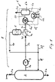
- Fig. 1 shows a first device for the recovery of nitrogen.
- the ethylene becomes raw polyethylene polymerized.
- a stripping column 2 follows the reactor arranged, which via the feed line 2 a fluid conducting with the reactor connected is. Inside the stripping column 2 is the raw polyethylene cleaned with a method known per se, by the raw Polyethylene using unreacted nitrogen Hydrocarbons are removed. The polyethylene cleaned in this way becomes fed to further processing via the derivation 2b.
- the stripping column 2 is connected to a nitrogen recovery device 1 in a fluid-conducting manner.
- a membrane device 4 with membrane 4a is connected to the stripping column 2 in a fluid-conducting manner via a feed line 7b, an oil-free compressor 3 and a feed line 7a.
- the compressor 3 is designed, for example, as a labyrinth piston compressor.
- a filter 5 is arranged downstream of the membrane device 4 via a connecting line 7d, the filter 5 being fluidly connected to the stripping column 2 via the connecting lines 7e, 7f.
- the membrane device 4 is also connected to a vacuum pump system 6 via the connecting line 7c.
- the vacuum pump system 6 comprises a liquid ring pump 6a, which, forming a liquid circuit, is connected in a fluid-conducting manner via the connecting lines 6d, 6e, 6f to a separator 6b, also referred to as a gas-liquid separator, and a cooler 6c to the cooling conductor 6h.
- the liquid ring pump 6a is arranged such that it generates a vacuum with respect to the membrane device 4.
- water is particularly suitable for use in the liquid circuit.
- the liquid and gaseous constituents are separated in the separator 6b, the gaseous components being discharged via the discharge line 6g, for example to a flare. In the illustrated embodiment, between 700 and 1500 kg of nitrogen (N 2 ) per hour are converted in stripping column 2.
- the gas mixture comprising ethylene and nitrogen is extracted using the Compressor 3 withdrawn from the stripping column 2 and the Membrane device 4 supplied.
- the membrane 4a has the property that it is much more permeable to hydrocarbons than to nitrogen.
- the Hydrocarbons, especially ethylene is produced through the Aspirated connecting line 7c, while the one depleted of ethylene Nitrogen in the filter 5 is filtered with activated carbon, and then cleaned the Stripping column 2 is fed.
- the nitrogen purified in this way can for example, have a purity of 99.5%.
- the membrane 4a can consist of a multi-layer composite, for example English also referred to as "multilayer composite membrane".
- a Such thin film membrane has, for example, a 10 to 100 times higher Permeability to hydrocarbons compared to nitrogen.
- That of the membrane device 4 with the help of the liquid ring pump 6a withdrawn ethylene is separated from the liquid in the separator 6b and the lead 6g fed.
- the ethylene withdrawn in this way can be burned be used, or a subsequent processing.
- the Withdrawn ethylene can also be used to manufacture polyethylene can be used by the polyethylene for example the reactor is fed.
- Additional nitrogen can be supplied via the connecting line 7f to compensate for the loss that occurs in the recovery process compensate.
- the nitrogen recovery device enables To produce polyethylene inexpensively.
- the loss of ethylene will reduced.
- the environmental impact and energy consumption Production of ethylene reduced.
- the compressor 3 shown in FIG. 2 is designed as a liquid ring compressor system 3, with a liquid ring compressor 3a, a separator 3b and a cooler 3c, the three latter components being connected via connecting lines 3d, 3e, 3f , and with the formation of a circuit, fluid are connected conductively.
- the cooler 3c is also connected to a cooling line 3h.
- water is preferably used as the conveying liquid.
- the exemplary embodiment shown in FIG. 2 has the advantage that the fluid drawn off from the stripping column 2 via the connecting line 7a is compressed isothermally or almost isothermally. In addition, the withdrawn fluid is washed in the liquid ring compressor 3a.
Abstract
Description
Die Erfindung betrifft ein Verfahren zur Rückgewinnung von Stickstoff bei der
Herstellung von Polyethylen gemäss dem Oberbegriff von Anspruch 1. Die
Erfindung betrifft weiter eine Vorrichtung zur Rückgewinnung von Stickstoff
bei der Herstellung von Polyethylen gemäss dem Oberbegriff von Anspruch
7.The invention relates to a process for the recovery of nitrogen in the
Production of polyethylene according to the preamble of
Polyethylen wird durch Polymerisation von Ethylen hergestellt. Nach dem Herstellen von Polyethylen muss dieses einem Reinigungsprozess unterzogen werden. Rohes Polyethylen enthält einen signifikanten Anteil an nicht reagierten Kohlenwassenstoffen. Bevor das rohe Polyethylen extrudiert wird, müssen die nicht reagierten Kohlenwasserstoffe entzogen werden. Diese Kohlenwasserstoffe werden in einer Stripping-Kolonne unter Verwendung von Stickstoff abgezogen. Üblicherweise werden die abgezogenen Kohlenwasserstoffe zusammen mit dem Stickstoff über einen Flare an die Umwelt abgegeben.Polyethylene is made by polymerizing ethylene. After this Manufacture of polyethylene requires a cleaning process be subjected. Raw polyethylene contains a significant amount of unreacted hydrocarbons. Before the raw polyethylene extrudes , the unreacted hydrocarbons must be removed. These hydrocarbons are placed in a stripping column Subtracted using nitrogen. Usually the withdrawn hydrocarbons together with the nitrogen over a Flare released to the environment.
Es ist Aufgabe der vorliegenden Erfindung ein wirtschaftlich vorteilhafteres Verfahren bzw. eine entsprechende Vorrichtung zur Erzeugung von Polyethylen vorzuschlagen.The object of the present invention is an economically more advantageous one Method or a corresponding device for generating Propose polyethylene.
Diese Aufgabe wird gelöst mit einem Verfahren aufweisend die Merkmale von
Anspruch 1. Die Unteransprüche 2 bis 6 betreffen weitere, vorteilhafte
Verfahrensschritte. Die Aufgabe wird weiter gelöst mit einer Vorrichtung
aufweisend die Merkmale von Anspruch 7. Die Unteransprüche 8 bis 11
betreffen weitere vorteilhafte Ausgestaltungen.This object is achieved with a method having the features of
Die Aufgabe wird insbesondere gelöst mit einem Verfahren zur Rückgewinnung von Stickstoff bei der Herstellung von Polyethylen,
- indem in einer Stripping-Kolonne das nicht polymerisierte Ethylen unter Verwendung von Stickstoff vom Polyethylen getrennt wird,
- indem ein Gasgemisch umfassend Ethylen und Stickstoff von der Stripping-Kolonne abgezogen und einer Membran zugeführt wird, welche derart ausgestaltet ist, dass das Ethylen zumindest teilweise vom Stickstoff abtrennt wird,
- indem der mit Ethylen abgereicherte Stickstoff gefiltert und danach zurückgewonnen wird,
- und indem das Ethylen mit einem Vakuumpumpsystem von der Membran abgezogen wird.
- by separating the unpolymerized ethylene from the polyethylene using nitrogen in a stripping column,
- by withdrawing a gas mixture comprising ethylene and nitrogen from the stripping column and feeding it to a membrane which is designed in such a way that the ethylene is at least partially separated from the nitrogen,
- by filtering the nitrogen-depleted nitrogen and then recovering it,
- and by withdrawing the ethylene from the membrane using a vacuum pump system.
Die Aufgabe wird zudem insbesondere gelöst mit einer Vorrichtung zur Rückgewinnung von Stickstoff bei der Herstellung von Polyethylen, umfassend
- einen Kompressor der Fluid leitend mit einer Stripping-Kolonne verbindbar ist,
- eine Membranvorrichtung welche derart ausgestaltet ist, dass diese aus einem Ethylen und Stickstoff umfassenden Gasgemisch den Stickstoff zumindest teilweise vom Ethylen abzutrennen erlaubt,
- eine Filtervorrichtung
- sowie ein Vakuumpumpsystem
- wobei die Membranvorrichtung Fluid leitend mit der Kompressor verbunden ist, und wobei die Membranvorrichtung einerseits mit der Filtervorrichtung und andererseits mit dem Vakuumpumpsystem Fluid leitend verbunden ist, und wobei der zurückgewonnene Stickstoff nach der Filtervorrichtung zur Verfügung steht.
- a compressor which can be fluidly connected to a stripping column,
- a membrane device which is designed in such a way that it allows at least partially the nitrogen to be separated from the ethylene from a gas mixture comprising ethylene and nitrogen,
- a filter device
- as well as a vacuum pump system
- wherein the membrane device is fluidly connected to the compressor, and the membrane device is fluidly connected on the one hand to the filter device and on the other hand to the vacuum pump system, and wherein the recovered nitrogen is available after the filter device.
In einem bevorzugten Verfahrensschritt wird der zurückgewonnene Stickstoff wieder der Stripping-Kolonne zugeführt. Das erfindungsgemässe Verfahren weist somit den Vorteil auf, dass der Stickstoff (N2) wieder verwertbar ist, wodurch die Herstellung von Polyethylen kostengünstiger wird. In a preferred process step, the recovered nitrogen is returned to the stripping column. The process according to the invention thus has the advantage that the nitrogen (N 2 ) can be recycled, as a result of which the production of polyethylene is less expensive.
In einem weiteren, bevorzugten Verfahrensschritt wird das zurückgewonnene Ethylen wieder dem Reaktor, in welchem die Polymerisation abläuft, zugeführt. Das erfindungsgemässe Verfahren weist somit den Vorteil auf, dass das Ethlen wieder verwertbar ist.In a further, preferred process step, the recovered Ethylene back to the reactor in which the polymerization takes place, fed. The method according to the invention thus has the advantage that ethlen is recyclable.
Das erfindungsgemässe Verfahren bzw. die Vorrichtung weisen somit den Vorteil auf, dass das Ethylen und/oder der Stickstoff mit einem derart hohen Reinheitsgrad gewonnen werden können, dass eine Wiederverwendung des Stickstoffs als Strippingmedium in der Stripping-Kolonne und ein Wiedereinsatz des Ethylens als Ausgangsprodukt im Reaktor möglich ist.The method and the device according to the invention thus have the Advantage that the ethylene and / or nitrogen with such a high Purity levels can be obtained that reuse the Nitrogen as a stripping medium in the stripping column and a Reuse of ethylene as a starting product in the reactor is possible.
In der Stripping-Kolonne wird das abgetrennte Ethylen zusammen mit dem Stickstoff, und gegebenenfalls noch mit weiteren Kohlenwasserstoffen, Polyethylenstaub und Kathalysatoranteilen, als Fluid bzw. Gasgemisch abgezogen, danach durch den Kompressor verdichtet, und danach einer Membran zugeführt. Zum Verdichten wird vorzugsweise ein Flüssigkeitsringkompressor verwendet, welcher vorzugsweise mit Wasser betrieben wird, und welcher das Fluid auf einen Druck von beispielsweise 10 bar bis 15 bar verdichtet. Ein derartiger Flüssigkeitsringkompressor verdichtet das Gasgemisch nahezu isotherm, was den Vorteil aufweist, dass die Temperatur des Gasgemisches auf Grund der Kompression nicht erhöht wird. Würde bei der Kompression eine wesentliche Temperaturerhöhung auftreten, so besteht die Gefahr, dass das im Gasgemisch enthaltene Etylen polymerisiert. Ein Flüssigkeitsringkompressor weist zudem den Vorteil auf, dass sowohl feste Anteile wie Polyethylenstaub als auch flüssige Anteile wie der Kathalysator, welche aus der Stripping-Kolonne mitgerissen werden, mit dem Wassersystem des Flüssigkeitsringkompressors ausgeschleust werden können. Im Flüssigkeitsringkompressor erfolgt somit ein Waschen des geförderten Fluides, wobei insbesondere der im Fluid enthaltene Polyethylenstaub ausgewaschen wird, im Wasser verbleibt, und beispielsweise im einem Dekanter abgezogen werden kann. Ein Flüssigkeitsringkompressor weist zudem den Vorteil auf, dass die Kathalysatoranteile durch das Wasser ausgewaschen werden. Bei der Herstellung von Polyethylen wird als Kathalysator häufig Hexan verwendet, ein Krebs erzeugendes Mittel. Dieses Hexan kann somit der Stripping-Kolonne zumindest teilweise entzogen werden. In the stripping column, the separated ethylene together with the Nitrogen, and optionally with further hydrocarbons, Polyethylene dust and catalyst components, as a fluid or gas mixture deducted, then compressed by the compressor, and then one Membrane supplied. A is preferably used for compaction Liquid ring compressor used, which preferably with water is operated, and which the fluid to a pressure of, for example, 10th compressed to 15 bar. Such a liquid ring compressor compresses the gas mixture almost isothermally, which has the advantage that the temperature of the gas mixture does not increase due to the compression becomes. Would increase the temperature significantly during compression occur, there is a risk that the ethylene contained in the gas mixture polymerized. A liquid ring compressor also has the advantage that both solid parts like polyethylene dust and liquid parts like the cathalyser, which is carried away from the stripping column, with the water system of the liquid ring compressor can. The liquid ring compressor is thus washed promoted fluid, in particular the fluid contained Polyethylene dust is washed out, remains in the water, and can be deducted in a decanter, for example. On Liquid ring compressor also has the advantage that the Parts of the catalyst are washed out by the water. In the Production of polyethylene, hexane is often used as a catalyst, a carcinogen. This hexane can thus be the stripping column at least partially withdrawn.
Das verdichtete Ethylen -Kohlenwasserstoffgas-Stickstoffgemisch, das sich im Flüssigkeitsringkompressor mit Wasserdampf sättigt, wird einer organophilen Membranfläche zugeführt, welche das Ethylen und die Kohlenwasserstoffe als Permeat passieren lässt, wogegen Wasserdampf und Stickstoff als Retentat zurückgehalten wird. In einer bevorzugten Ausführungsform wird der Stickstoff zusammen mit dem Wasserdampf der Stripping-Kolonne wieder zugeführt. Der Stripping-Vorgang erfolgt mit dem Stickstoff/Wasserdampfgemisch, wobei das zurückgeführte Stickstoff/Wasserdampfgemisch nach der Membran vorzugsweise durch einen Aktivkohlefilter geleitet wird, um den Rest des krebserzeugenden Hexans auf eine vertretbare Konzentration zu reduzieren. Ein Vorteil ist somit die Tatsache, dass der allgemeine Stickstoffverbrauch auf ein Minimum reduziert wird.The compressed ethylene-hydrocarbon gas-nitrogen mixture, which is saturates with water vapor in the liquid ring compressor, one becomes organophilic membrane surface supplied, which the ethylene and the Permits hydrocarbons to pass through, while water vapor and Nitrogen is retained as a retentate. In a preferred one Embodiment is the nitrogen along with the water vapor Stripping column fed again. The stripping process takes place with the Nitrogen / water vapor mixture, the recycled Nitrogen / water vapor mixture after the membrane preferably through An activated carbon filter is passed to the rest of the carcinogen Reduce Hexans to an acceptable concentration. So that's an advantage the fact that the general nitrogen consumption to a minimum is reduced.
Der durch den Kompressor bewirkte, relativ hohe Druck von beispielsweise 10 bis 15 bar weist den Vorteil auf, dass die nachfolgend angeordnete Membran eine kleine Fläche aufweisen kann, und dass die Membran eine höhere Permeabilität aufweist, sodass die Membranvorrichtung relativ klein ausgestaltet sein kann. Trotz des hohen Druckes tritt am Flüssigkeitsringkompressor keine Polymerisation auf, da die Kompression im wesentlichen isotherm erfolgt. Das in der erfindungsgemässen Vorrichtung geförderte Fluid muss weder stark erwärmt noch stark abgekühlt werden, sodass das geförderte Fluid weder eine besonders hohe noch eine besonders tiefe Temperatur aufweisen. Insbesondere tritt auch keine Verflüssigung von Bestandteilen des Fluides auf. Dieser Aspekt ist insbesondere für die Lebensdauer der Membran von Wichtigkeit, da die Membran an sich temperaturempfindlich ist. Ein weiterer Vorteil der erfindungsgemässen Vorrichtung ist die Tatsache, dass auf Grund des in der Anlage vorherrschenden, relativ hohen Drucks, die Anlage sehr klein und kompakt ausgestaltet und dimensioniert werden kann.The relatively high pressure caused by the compressor, for example 10 to 15 bar has the advantage that the one arranged below Membrane can have a small area, and that the membrane has higher permeability, so that the membrane device is relatively small can be designed. Despite the high pressure occurs on Liquid ring compressor no polymerization due to the compression in the essentially isothermal. That in the device according to the invention conveyed fluid does not have to be heated up or cooled down, so that the fluid delivered is neither particularly high nor high have a particularly low temperature. In particular, none occurs Liquefaction of components of the fluid. That aspect is of particular importance for the life of the membrane, since the Membrane itself is temperature sensitive. Another advantage of The inventive device is the fact that due to the in Plant prevailing, relatively high pressure, the plant is very small and can be compactly designed and dimensioned.
Das Vakuumpumpsystem und der Kompressor umfassen vorzugsweise einen Flüssigkeitsringkompressor, wie dieser beispielsweise in der Druckschrift EP 0 967 393 A2 offenbart ist. The vacuum pump system and the compressor preferably comprise one Liquid ring compressor, such as this in the publication EP 0 967 393 A2.
Die Erfindung wird nachfolgend an Hand von Ausführungsbeispielen beschrieben.
- Fig. 1
- zeigt schematisch eine Vorrichtung zur Rückgewinnung von Stickstoff bei der Herstellung von Polyethlyen;
- Fig. 2
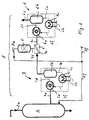
- zeigt schematisch eine weitere Vorrichtung zur Rückgewinnung von Stickstoff bei der Herstellung von Polyethylen.
- Fig. 1
- schematically shows a device for the recovery of nitrogen in the production of polyethylene;
- Fig. 2
- shows schematically another device for the recovery of nitrogen in the production of polyethylene.
Fig. 1 zeigt eine erste Vorrichtung zur Rückgewinnung von Stickstoff. In
einem nicht dargestellten Reaktor wird das Ethylen zu rohem Polyethylen
polymerisiert. Dem Reaktor nachfolgend ist eine Stripping-Kolonne 2
angeordnet, welche über die Zuleitung 2a Fluid leitend mit dem Reaktor
verbunden ist. Innerhalb der Stripping-Kolonne 2 wird das rohe Polyethylen
mit einem an sich bekannten Verfahren gereinigt, indem dem rohen
Polyethylen unter Verwendung von Stickstoff die nicht reagierten
Kohlenwasserstoffe entzogen werden. Das derart gereinigte Polyethylen wird
über die Ableitung 2b einer weiteren Verarbeitung zugeführt.Fig. 1 shows a first device for the recovery of nitrogen. In
In a reactor, not shown, the ethylene becomes raw polyethylene
polymerized. A stripping
Die Stripping-Kolonne 2 ist Fluid leitend mit einer
Stickstoffrückgewinnungsvorrichtung 1 verbunden. Eine Membranvorrichtung
4 mit Membran 4a ist über eine Zuleitung 7b, einen ölfreien Kompressor 3
und eine Zuleitung 7a Fluid leitend mit der Stripping-Kolonne 2 verbunden.
Der Kompressor 3 ist beispielsweise als Labyrinth-Kolbenkompressor
ausgestaltet. Der Membranvorrichtung 4 ist über eine Verbindungsleitung 7d
ein Filter 5 nachgeordnet, wobei das Filter 5 über die Verbindungsleitungen
7e, 7f Fluid leitend mit der Stripping-Kolonne 2 verbunden ist. Die
Membranvorrichtung 4 ist über die Verbindungsleitung 7c zudem mit einem
Vakuumpumpsystem 6 verbunden. Das Vakuumpumpsystem 6 umfasst eine
Flüssigkeitsringpumpe 6a, welche, unter Ausbildung eines
Flüssigkeitskreislaufes, über die Verbindungsleitungen 6d, 6e, 6f Fluid
leitend mit einem Separator 6b, auch als Gas-Flüssigkeitsabscheider
bezeichnet, sowie einem Kühler 6c mit Kühlleiter 6h verbunden ist. Die
Flüssigkeitsringpumpe 6a ist derart angeordnet, dass sie bezüglich der
Membranvorrichtung 4 ein Vakuum erzeugt. Nebst anderen Flüssigkeiten ist
zur Verwendung im Flüssigkeitskreislauf insbesondere Wasser geeignet. Im
Separator 6b werden die flüssigen und gasförmigen Bestandteile getrennt,
wobei die gasförmigen Anteile über die Ableitung 6g abgeführt werden,
beispielsweise an einen Flare. Im dargestellten Ausführungsbeispiel wird in
der Stripping-Kolonne 2 zwischen 700 und 1500 kg Stickstoff (N2) pro Stunde
umgesetzt.The stripping
Das Gasgemisch umfassend Ethylen und Stickstoff wird mit Hilfe des
Kompressors 3 aus der Stripping-Kolonne 2 abgezogen und der
Membranvorrichtung 4 zugeführt. Die Membran 4a hat die Eigenschaft, dass
sie für Kohlenwasserstoffe wesentlich durchlässiger ist als für Stickstoff. Die
Kohlenwasserstoffe, insbesondere das Ethylen, wird über die
Verbindungsleitung 7c abgesaugt, wogegen der mit Ethylen abgereicherte
Stickstoff im Filter 5 mit Aktivekohle gefiltert wird, und danach gereinigt der
Stripping-Kolonne 2 zugeführt wird. Der derart gereinigte Stickstoff kann
beispielsweise eine Reinheit von 99,5% aufweisen. Die Membran 4a kann
beispielsweise aus einem Mehrschichtverbundwerkstoff bestehen, im
Englischen auch als "Multilayer Composite Membrane" bezeichnet. Eine
derartige Dünnfilm-Membran weist beispielsweise eine 10 bis 100 mal höhere
Permeabilität für Kohlenwasserstoffe im Vergleich zu Stickstoff auf.The gas mixture comprising ethylene and nitrogen is extracted using the
Das von der Membranvorrichtung 4 mit Hilfe der Flüssigkeitsringpumpe 6a
abgezogene Ethylen wird im Separator 6b von der Flüssigkeit getrennt und
der Ableitung 6g zugeführt. Das derart abgezogene Ethylen kann verbrannt
werden, oder einer nachfolgenden Verarbeitung zugeführt werden. Das
abgezogene Ethylen kann auch wieder zur Herstellung von Polyethylen
verwendet werden, indem das Polyethylen beispielsweise dem Reaktor
zugeführt wird.That of the
Über die Verbindungsleitung 7f kann zusätzlicher Stickstoff zugeführt
werden, um den im Rückgewinnungsverfahren auftretenden Verlust zu
kompensieren.Additional nitrogen can be supplied via the connecting
Die erfindungsgemässe Stickstoffrückgewinnungsvorrichtung ermöglicht Polyethylen kostengünstig herzustellen. Der Verlust an Ethylen wird reduziert. Zudem wird die Umweltbelastung sowie der Energieverbrauch zur Herstellung von Ethylen reduziert. The nitrogen recovery device according to the invention enables To produce polyethylene inexpensively. The loss of ethylene will reduced. In addition, the environmental impact and energy consumption Production of ethylene reduced.
Im Unterschied zu dem in Fig. 1 dargestellten Ausführungsbeispiel ist der in
Fig. 2 dargestellte Kompressor 3 als ein Flüssigkeitsringkompressorsystem 3
ausgestaltet, mit einem Flüssigkeitsringkompressor 3a, einem Separator 3b
und einem Kühler 3c, wobei die drei letztgenannten Komponenten über
Verbindungsleitungen 3d, 3e, 3f, und unter Ausbildung eines Kreislaufes,
Fluid leitend verbunden sind. Der Kühler 3c ist zudem mit einer Kühlleitung
3h verbunden. In diesem Kreislauf wird als Förderflüssigkeit vorzugsweise
Wasser verwendet.
Das in Fig. 2 dargestellte Ausführungsbeispiel weist den Vorteil auf, dass das
aus der Stripping-Kolonne 2 über die Verbindungsleitung 7a abgezogene
Fluid isotherm oder nahezu isotherm komprimiert wird. Zudem wird das
abgezogene Fluid im Flüssigkeitsringkompressor 3a gewaschen.In contrast to the exemplary embodiment shown in FIG. 1, the
The exemplary embodiment shown in FIG. 2 has the advantage that the fluid drawn off from the stripping
Claims (11)
Priority Applications (1)
| Application Number | Priority Date | Filing Date | Title |
|---|---|---|---|
| EP00810678A EP1159999A1 (en) | 2000-05-31 | 2000-07-28 | Method and apparatus for the recuperation of nitrogen during the polyethelene production |
Applications Claiming Priority (3)
| Application Number | Priority Date | Filing Date | Title |
|---|---|---|---|
| EP00810483 | 2000-05-31 | ||
| EP00810483 | 2000-05-31 | ||
| EP00810678A EP1159999A1 (en) | 2000-05-31 | 2000-07-28 | Method and apparatus for the recuperation of nitrogen during the polyethelene production |
Publications (1)
| Publication Number | Publication Date |
|---|---|
| EP1159999A1 true EP1159999A1 (en) | 2001-12-05 |
Family
ID=26073906
Family Applications (1)
| Application Number | Title | Priority Date | Filing Date |
|---|---|---|---|
| EP00810678A Withdrawn EP1159999A1 (en) | 2000-05-31 | 2000-07-28 | Method and apparatus for the recuperation of nitrogen during the polyethelene production |
Country Status (1)
| Country | Link |
|---|---|
| EP (1) | EP1159999A1 (en) |
Cited By (3)
| Publication number | Priority date | Publication date | Assignee | Title |
|---|---|---|---|---|
| EP2197562A1 (en) * | 2007-08-30 | 2010-06-23 | Environmental Protection Agency | Liquid separation by membrane assisted vapor process |
| CN107513005A (en) * | 2017-09-27 | 2017-12-26 | 中科瑞奥能源科技股份有限公司 | The technique and system of ethene, iso-butane and nitrogen are reclaimed from polyethylene engineering tail gas |
| CN112265970A (en) * | 2020-10-22 | 2021-01-26 | 吉林工程技术师范学院 | Polyethylene tail gas completely-recycling device |
Citations (4)
| Publication number | Priority date | Publication date | Assignee | Title |
|---|---|---|---|---|
| US4501885A (en) * | 1981-10-14 | 1985-02-26 | Phillips Petroleum Company | Diluent and inert gas recovery from a polymerization process |
| US5127926A (en) * | 1991-05-06 | 1992-07-07 | Membrane Technology & Research, Inc. | Membrane process for treating pump exhausts |
| EP0585161A1 (en) * | 1992-08-26 | 1994-03-02 | L'air Liquide, Societe Anonyme Pour L'etude Et L'exploitation Des Procedes Georges Claude | Fast response membrane generator using heat accumulation |
| US5769927A (en) * | 1997-01-24 | 1998-06-23 | Membrane Technology And Research, Inc. | Monomer recovery process |
-
2000
- 2000-07-28 EP EP00810678A patent/EP1159999A1/en not_active Withdrawn
Patent Citations (4)
| Publication number | Priority date | Publication date | Assignee | Title |
|---|---|---|---|---|
| US4501885A (en) * | 1981-10-14 | 1985-02-26 | Phillips Petroleum Company | Diluent and inert gas recovery from a polymerization process |
| US5127926A (en) * | 1991-05-06 | 1992-07-07 | Membrane Technology & Research, Inc. | Membrane process for treating pump exhausts |
| EP0585161A1 (en) * | 1992-08-26 | 1994-03-02 | L'air Liquide, Societe Anonyme Pour L'etude Et L'exploitation Des Procedes Georges Claude | Fast response membrane generator using heat accumulation |
| US5769927A (en) * | 1997-01-24 | 1998-06-23 | Membrane Technology And Research, Inc. | Monomer recovery process |
Cited By (5)
| Publication number | Priority date | Publication date | Assignee | Title |
|---|---|---|---|---|
| EP2197562A1 (en) * | 2007-08-30 | 2010-06-23 | Environmental Protection Agency | Liquid separation by membrane assisted vapor process |
| EP2197562A4 (en) * | 2007-08-30 | 2010-12-15 | Environmental Prot Agency | Liquid separation by membrane assisted vapor process |
| CN107513005A (en) * | 2017-09-27 | 2017-12-26 | 中科瑞奥能源科技股份有限公司 | The technique and system of ethene, iso-butane and nitrogen are reclaimed from polyethylene engineering tail gas |
| CN107513005B (en) * | 2017-09-27 | 2022-11-15 | 中科瑞奥能源科技股份有限公司 | Process and system for recovering ethylene, isobutane and nitrogen from polyethylene engineering tail gas |
| CN112265970A (en) * | 2020-10-22 | 2021-01-26 | 吉林工程技术师范学院 | Polyethylene tail gas completely-recycling device |
Similar Documents
| Publication | Publication Date | Title |
|---|---|---|
| DE60112813T2 (en) | METHOD FOR TREATING A CONSUMED GLYCOL TUBE | |
| DE69926526T2 (en) | RECOVERY OF C02 AND H2 FROM PSA EXHAUST GASES IN A H2 PRODUCTION PLANT | |
| DE60009920T2 (en) | METHOD FOR REMOVING CONTAMINATION FROM A GAS USING POLYETHYLENE GLYCLE | |
| DE60033881T2 (en) | Process for treating a waste oil | |
| EP0144956B1 (en) | Process and apparatus for regenerating a solvent | |
| WO2017020919A1 (en) | Method for obtaining a helium-rich product fraction | |
| DE2441304C3 (en) | Method and device for reducing the content of gaseous monomers in polyvinyl chloride-water dispersions | |
| GB2092170A (en) | Process for the purification of crude glyceride oil compossitions | |
| DE2818127C2 (en) | Method and device for the ultrafiltration of liquid mixtures | |
| DE102015005203A1 (en) | Process and apparatus for decomposing synthesis gases | |
| DE2713359A1 (en) | PROCESS FOR THE FRACTIONATION OF CRACK GASES WITH THE HELP OF REFRIGERATION TECHNOLOGY | |
| EP1159999A1 (en) | Method and apparatus for the recuperation of nitrogen during the polyethelene production | |
| DE102009034949A1 (en) | Process for the preparation of a suspension | |
| EP0230543B1 (en) | Process for recycling spent oil | |
| DE60320477T2 (en) | Method for lowering or removing NH3 / HF by-products in the preparation of nitrogen triflouride | |
| EP1160000A1 (en) | Method and apparatus for the recuperation of nitrogen and/or propylene during the polypropylene production | |
| DE602005004939T2 (en) | EPOXIDATION OF PROPYLENE WHERE A MEMBRANE IS USED FOR SEPARATING THE PHOSPIN AND / OR PHOSPHINOXIDE PROMOTER FROM THE PRODUCT | |
| DE3237930C1 (en) | Cleaning of hydrogen-free, fluorinated lubricants | |
| DE2854151A1 (en) | METHOD FOR PRODUCING COPOLYMERISATS OF AETHYLENE | |
| DE2521507A1 (en) | METHOD OF TREATMENT OF WATER VAPOR FORMED WHEN CONCENTRATING AN AQUATIC UREA SOLUTION | |
| EP1160001A1 (en) | Method and apparatus to compress a fluid containing ethylene and nitrogen | |
| EP1847587B1 (en) | Process for reprocessing waste oil to obtain base oils with a high viscosity index | |
| DE2618244C2 (en) | Process for the production of unreacted monomers from polymers of vinyl chloride | |
| DE102021203708B3 (en) | Process and device for the recycling of Low Density Polyethylene (LDPE) | |
| DE102007055297A1 (en) | Method for degassing of waste water containing dissolved gases, loaded with soot by oil- and/or coal gasification, comprises separating gas dissolved in the waste water by vacuum treatment to produce degassed waste water |
Legal Events
| Date | Code | Title | Description |
|---|---|---|---|
| PUAI | Public reference made under article 153(3) epc to a published international application that has entered the european phase |
Free format text: ORIGINAL CODE: 0009012 |
|
| AK | Designated contracting states |
Kind code of ref document: A1 Designated state(s): AT BE CH CY DE DK ES FI FR GB GR IE IT LI LU MC NL PT SE |
|
| AX | Request for extension of the european patent |
Free format text: AL;LT;LV;MK;RO;SI |
|
| AKX | Designation fees paid | ||
| REG | Reference to a national code |
Ref country code: DE Ref legal event code: 8566 |
|
| STAA | Information on the status of an ep patent application or granted ep patent |
Free format text: STATUS: THE APPLICATION IS DEEMED TO BE WITHDRAWN |
|
| 18D | Application deemed to be withdrawn |
Effective date: 20020606 |