EP1158803A2 - Rendering device for generating a display image - Google Patents
Rendering device for generating a display image Download PDFInfo
- Publication number
- EP1158803A2 EP1158803A2 EP01112379A EP01112379A EP1158803A2 EP 1158803 A2 EP1158803 A2 EP 1158803A2 EP 01112379 A EP01112379 A EP 01112379A EP 01112379 A EP01112379 A EP 01112379A EP 1158803 A2 EP1158803 A2 EP 1158803A2
- Authority
- EP
- European Patent Office
- Prior art keywords
- vehicle
- generating
- rudder angle
- display image
- calculation
- Prior art date
- Legal status (The legal status is an assumption and is not a legal conclusion. Google has not performed a legal analysis and makes no representation as to the accuracy of the status listed.)
- Withdrawn
Links
- 238000009877 rendering Methods 0.000 title claims abstract description 62
- 238000000034 method Methods 0.000 claims description 24
- 238000012545 processing Methods 0.000 description 26
- 238000005070 sampling Methods 0.000 description 25
- 238000010586 diagram Methods 0.000 description 21
- 108091093018 PVT1 Proteins 0.000 description 9
- 238000001514 detection method Methods 0.000 description 9
- 102100038712 Cap-specific mRNA (nucleoside-2'-O-)-methyltransferase 1 Human genes 0.000 description 7
- 101710203121 Cap-specific mRNA (nucleoside-2'-O-)-methyltransferase 1 Proteins 0.000 description 7
- 101100258233 Caenorhabditis elegans sun-1 gene Proteins 0.000 description 5
- 102100038716 Cap-specific mRNA (nucleoside-2'-O-)-methyltransferase 2 Human genes 0.000 description 5
- 101710203126 Cap-specific mRNA (nucleoside-2'-O-)-methyltransferase 2 Proteins 0.000 description 5
- 101100024583 Mus musculus Mtf1 gene Proteins 0.000 description 5
- 230000004044 response Effects 0.000 description 4
- 102100040079 A-kinase anchor protein 4 Human genes 0.000 description 3
- 101100490737 Mus musculus Akap4 gene Proteins 0.000 description 3
- 238000012986 modification Methods 0.000 description 3
- 230000004048 modification Effects 0.000 description 3
- 230000007935 neutral effect Effects 0.000 description 2
- 101150101654 PSR1 gene Proteins 0.000 description 1
- 238000006243 chemical reaction Methods 0.000 description 1
- 238000005516 engineering process Methods 0.000 description 1
- 239000004973 liquid crystal related substance Substances 0.000 description 1
- 239000007787 solid Substances 0.000 description 1
- 238000013519 translation Methods 0.000 description 1
Images


Classifications
-
- H—ELECTRICITY
- H04—ELECTRIC COMMUNICATION TECHNIQUE
- H04N—PICTORIAL COMMUNICATION, e.g. TELEVISION
- H04N7/00—Television systems
- H04N7/18—Closed-circuit television [CCTV] systems, i.e. systems in which the video signal is not broadcast
-
- B—PERFORMING OPERATIONS; TRANSPORTING
- B60—VEHICLES IN GENERAL
- B60R—VEHICLES, VEHICLE FITTINGS, OR VEHICLE PARTS, NOT OTHERWISE PROVIDED FOR
- B60R1/00—Optical viewing arrangements; Real-time viewing arrangements for drivers or passengers using optical image capturing systems, e.g. cameras or video systems specially adapted for use in or on vehicles
- B60R1/20—Real-time viewing arrangements for drivers or passengers using optical image capturing systems, e.g. cameras or video systems specially adapted for use in or on vehicles
- B60R1/22—Real-time viewing arrangements for drivers or passengers using optical image capturing systems, e.g. cameras or video systems specially adapted for use in or on vehicles for viewing an area outside the vehicle, e.g. the exterior of the vehicle
- B60R1/23—Real-time viewing arrangements for drivers or passengers using optical image capturing systems, e.g. cameras or video systems specially adapted for use in or on vehicles for viewing an area outside the vehicle, e.g. the exterior of the vehicle with a predetermined field of view
- B60R1/27—Real-time viewing arrangements for drivers or passengers using optical image capturing systems, e.g. cameras or video systems specially adapted for use in or on vehicles for viewing an area outside the vehicle, e.g. the exterior of the vehicle with a predetermined field of view providing all-round vision, e.g. using omnidirectional cameras
-
- H—ELECTRICITY
- H04—ELECTRIC COMMUNICATION TECHNIQUE
- H04N—PICTORIAL COMMUNICATION, e.g. TELEVISION
- H04N7/00—Television systems
- H04N7/18—Closed-circuit television [CCTV] systems, i.e. systems in which the video signal is not broadcast
- H04N7/181—Closed-circuit television [CCTV] systems, i.e. systems in which the video signal is not broadcast for receiving images from a plurality of remote sources
-
- B—PERFORMING OPERATIONS; TRANSPORTING
- B60—VEHICLES IN GENERAL
- B60R—VEHICLES, VEHICLE FITTINGS, OR VEHICLE PARTS, NOT OTHERWISE PROVIDED FOR
- B60R2300/00—Details of viewing arrangements using cameras and displays, specially adapted for use in a vehicle
- B60R2300/10—Details of viewing arrangements using cameras and displays, specially adapted for use in a vehicle characterised by the type of camera system used
- B60R2300/105—Details of viewing arrangements using cameras and displays, specially adapted for use in a vehicle characterised by the type of camera system used using multiple cameras
-
- B—PERFORMING OPERATIONS; TRANSPORTING
- B60—VEHICLES IN GENERAL
- B60R—VEHICLES, VEHICLE FITTINGS, OR VEHICLE PARTS, NOT OTHERWISE PROVIDED FOR
- B60R2300/00—Details of viewing arrangements using cameras and displays, specially adapted for use in a vehicle
- B60R2300/30—Details of viewing arrangements using cameras and displays, specially adapted for use in a vehicle characterised by the type of image processing
- B60R2300/302—Details of viewing arrangements using cameras and displays, specially adapted for use in a vehicle characterised by the type of image processing combining image information with GPS information or vehicle data, e.g. vehicle speed, gyro, steering angle data
-
- B—PERFORMING OPERATIONS; TRANSPORTING
- B60—VEHICLES IN GENERAL
- B60R—VEHICLES, VEHICLE FITTINGS, OR VEHICLE PARTS, NOT OTHERWISE PROVIDED FOR
- B60R2300/00—Details of viewing arrangements using cameras and displays, specially adapted for use in a vehicle
- B60R2300/30—Details of viewing arrangements using cameras and displays, specially adapted for use in a vehicle characterised by the type of image processing
- B60R2300/304—Details of viewing arrangements using cameras and displays, specially adapted for use in a vehicle characterised by the type of image processing using merged images, e.g. merging camera image with stored images
-
- B—PERFORMING OPERATIONS; TRANSPORTING
- B60—VEHICLES IN GENERAL
- B60R—VEHICLES, VEHICLE FITTINGS, OR VEHICLE PARTS, NOT OTHERWISE PROVIDED FOR
- B60R2300/00—Details of viewing arrangements using cameras and displays, specially adapted for use in a vehicle
- B60R2300/40—Details of viewing arrangements using cameras and displays, specially adapted for use in a vehicle characterised by the details of the power supply or the coupling to vehicle components
- B60R2300/404—Details of viewing arrangements using cameras and displays, specially adapted for use in a vehicle characterised by the details of the power supply or the coupling to vehicle components triggering from stand-by mode to operation mode
-
- B—PERFORMING OPERATIONS; TRANSPORTING
- B60—VEHICLES IN GENERAL
- B60R—VEHICLES, VEHICLE FITTINGS, OR VEHICLE PARTS, NOT OTHERWISE PROVIDED FOR
- B60R2300/00—Details of viewing arrangements using cameras and displays, specially adapted for use in a vehicle
- B60R2300/70—Details of viewing arrangements using cameras and displays, specially adapted for use in a vehicle characterised by an event-triggered choice to display a specific image among a selection of captured images
-
- B—PERFORMING OPERATIONS; TRANSPORTING
- B60—VEHICLES IN GENERAL
- B60R—VEHICLES, VEHICLE FITTINGS, OR VEHICLE PARTS, NOT OTHERWISE PROVIDED FOR
- B60R2300/00—Details of viewing arrangements using cameras and displays, specially adapted for use in a vehicle
- B60R2300/80—Details of viewing arrangements using cameras and displays, specially adapted for use in a vehicle characterised by the intended use of the viewing arrangement
- B60R2300/802—Details of viewing arrangements using cameras and displays, specially adapted for use in a vehicle characterised by the intended use of the viewing arrangement for monitoring and displaying vehicle exterior blind spot views
Definitions
- the present invention relates to rendering devices and, more specifically, to a rendering device for processing images of around a vehicle captured by image capture devices, and generating an image for display on a display device.
- the drive assistant device is placed in a vehicle, and includes two wheel speed sensors, a computing unit, a graphic controller corresponding to the conventional rendering device, and a display.
- One of the wheel speed sensors takes charge of two wheels on the left side of the vehicle, and detects a travelling quantity thereof.
- detected is a travelling quantity by two other wheels on the right side of the vehicle.
- detected quantities are accumulated together by the computing unit, and based on the accumulated value, a radius of a circle traceable by the vehicle, when rotated, is estimated.
- the graphic controller Based on the estimated rotation radius, the graphic controller generates an image showing predictive trajectories on the road surface. The resulting image is displayed on the display.
- Such drive assistant device carries two problems.
- a driver of the vehicle needs to be attentive, when parking, if any part of the vehicle with some height from the ground such as front and rear bumpers, mirrors, and fenders hits any object (e.g. , other vehicles, wall) in a close range.
- the image generated by the graphic controller only shows predictive trajectories on the road surface. Therefore, with such image on the display, the driver finds it difficult to determine if his/her bumper, and the like, is likely to hit any object therearound.
- the driver when parallel parking, the driver may have a hard time to park his/her vehicle if the initial position thereof is not appropriate. If failed, the driver tries again all the way from the beginning. During that time, any information about trajectories so far tried but failed may help the driver not to try the same trajectories.
- displayed on the conventional drive assistant device are only the predictive trajectories on the road surface, the driver thus cannot learn from failure.
- the display image provided by the conventional drive assistant device is not driver-friendly enough.
- an object of the present invention is to provide a rendering device, a display image generated thereby being informative enough for the driver.
- the present invention is directed to a rendering device for generating a display image for drive assistance, the device comprising: a first generation part for generating a surrounding image corresponding to an area surrounding the vehicle; a reception part for receiving a current rudder angle from a rudder angle sensor placed in the vehicle; a calculation part for calculating, based on the rudder angle received by the reception part, a three-dimensional predictive trajectory of the vehicle; and a second generation part for generating the display image showing the three-dimensional predictive trajectory calculated in the calculation part rendered on the surrounding image generated by the first generation part.
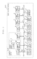
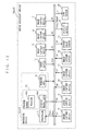
- FIG. 1 is a block diagram showing the hardware structure of a rendering device Urnd1 according to a first embodiment of the present invention.
- the rendering device Urnd1 includes a processor 1, program memory 2, and a working area 3.
- the program memory 2 is typically ROM (Read Only Memory), and stores a program PGa for defining the processing procedure in the processor 1.
- the program memory 2 also stores vehicle model data Dmd, which will be described below.
- FIGS. 2A and 2B are diagrams for demonstrating the vehicle model data Dmd.
- FIG. 2A is a slanted view of a vehicle Vusr standing still on a road surface Frd
- FIG. 2B is a diagram showing the top view of the vehicle Vusr of FIG. 2A viewed from a virtual viewpoint Pvt1 .
- a longitudinal plane passing through both a midpoint of a line between rotation centers of the front wheels, and another midpoint of a line between rotation centers of the rear wheels is referred to as a longitudinal median plane Fwc.
- the longitudinal median plane Fwc is rotated by 90 degrees around a vertical line passing through the center of the vehicle Vusr, and the resulting lateral plane is referred to as a lateral median plane Flc .
- These longitudinal median plane Fwc and lateral median plane F1c are indicated in FIG. 2B by a one-dot line and a two-dot line, respectively.
- FIGS. 2A and 2B both show, a little away from the vehicle Vusr, a first 3D (three dimensional) coordinate system CSa including three axes of X, Y, and Z.
- the Z-axis is equal to a line of intersection of the longitudinal median plane Fwc and the lateral median plane Flc .
- the X-axis is equal to a line of intersection of the lateral median plane Flc and the road surface Frd, while the Y-axis of the longitudinal median plane Fwc and the road surface Frd.
- an origin Oa of the first 3D coordinate system Csa is a point of intersection of the road surface Frd, the longitudinal median plane Fwc, and the lateral median plane F1c .
- the virtual viewpoint Pvt1 in FIGS. 2A and 2B is previously set high up above the vehicle Vusr, specifically 3D coordinates of which is (0, 0, zv).
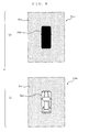
- the vehicle model data Dmd represents, as shown in FIG. 3, a vehicle model image Smd.
- the vehicle model image Smd shows the vehicle Vusr on the road surface Frd viewed from the virtual viewpoint Pvt1, and reduced in size by a predetermined scaling factor Fscl.
- the working area 3 is typically RAM (Random Access Memory) , and used by the processor 1 when executing the program PGa.
- the rendering device Urnd1 in such structure is typically incorporated into the drive assistant device Uast1 .
- the drive assistant device Uast1 is placed in the vehicle Vusr, and includes an input device 4, eight image capture devices 5 to 12, a rudder angle sensor 13, and a display device 14.
- the input device 4 is, typically, operated by the driver when he/she parks the vehicle Vusr .
- the input device 4 generates a start instruction signal Istr, and transmits the start instruction signal Istr to the processor 1.
- this start instruction signal Istr instructs the processor 1 to start executing the program PGa.
- FIGS. 4A and 4B show the positions of the vehicle Vusr, and their positions are exemplarily shown in FIGS. 4A and 4B.
- FIG. 4A shows four planes of the longitudinal median plane Fwc, the lateral median plane Flc , a first reference plane Frf1 , and a second reference plane Frf2 .
- the longitudinal and lateral median planes Fwc and Flc are both rotated by 45 degrees, as a rotation axis, with respect to a line of intersection thereof, and the resulting planes are the first and second reference planes Frf1 and Frf2.
- the area surrounding the vehicle Vusr is divided into eight regions R1 to R8.
- the regions R1, R2, R7, and R8 are located on the front side of the vehicle Vusr, while the regions R3, R4, R5, and R6 on the rear side.
- the front side denotes the front-half of the vehicle Vusr with reference to the lateral median plane Flc, and the rear side the rear-half.
- the heading direction of the vehicle Vusr is A1 , which is denoted by an arrow in the drawing.
- the image capture devices 5 and 6 are both fixedly placed at the front-end of the vehicle Vusr.
- the image capture device 5 captures an image corresponding to the region R1 of FIG. 4A as a surrounding image S1, which is enclosed by dotted lines in the drawing.
- the first surrounding image S1 shows an area ahead of the vehicle Vusr on the right side, inclusive of the road surface Frd.
- the image capture device 6 is similarly in charge of the area ahead of the vehicle Vusr but on the left side, inclusive of the road surface Frd, and captures an image corresponding to the region R8.
- a surrounding image S2 which is enclosed by one-dotted lines.
- the image capture devices 7 and 8 are both fixedly placed on the right side of the vehicle Vusr with respect to the heading direction indicated by an arrow of A1, and take charge of an area on the right side of the vehicle Vusr. Specifically, the image capture device 7 is directed toward the rear-right side and takes charge of the area corresponding to the region R3, while the image capture device 8 is directed toward the front-right side and takes charge of the area corresponding to the region R2.
- captured images are respectively referred to as surrounding images S3 and S4, both inclusive of the road surface Frd.
- the image capture devices 9 and 10 are both fixedly placed at the rear-end of the vehicle Vusr. Specifically, the image capture device 9 takes charge of an area rear of the vehicle Vusr on the left side, inclusive of the road surface Frd, and captures an image corresponding to the region R5. Thus captured image is referred to as a surrounding image S5.
- the image capture device 10 is similarly in charge of the area rear of the vehicle Vusr but on the right side, inclusive of the road surface Frd, and captures an image corresponding to the region R4. Thus captured image is referred to as a surrounding image S6.
- the image capture devices 11 and 12 are both fixedly placed on the left side of the vehicle Vusr , and take charge of an area on the left side of the vehicle Vusr. Specifically, the image capture device 11 is directed toward the front-left side and takes charge of the area corresponding to the region R7, while the image capture device 12 is directed toward the rear-left side and takes charge of the area corresponding to the region R6.
- captured images are respectively referred to as surrounding images S7 and S8, both inclusive of the road surface Frd.
- those surrounding images S1 to S8 do not limitedly correspond to the regions R1 to R8, but each extensively include its adjacent regions.
- the surrounding image S1 which mainly corresponds to the region R1, partially includes the bordering area of each adjacent surrounding images S2 and S8.
- the rudder angle sensor 13 detects a rudder angle ⁇ of the steering wheel of the vehicle Vusr, and transmits the detected rudder angle 0 to the processor 1.
- the rudder angle ⁇ here indicates at what angle the steering wheel is turned with respect to the initial position.
- the steering wheel is considered in the initial position when not turned, that is, when the vehicle Vusr is in the straight-ahead position.
- the display device 14 is typically a liquid crystal display.
- the processor 1 then generates an image capture instruction signal Icpt, and transmits the image capture instruction signal Icpt to all of the image capture devices 5 to 12 (step S2).
- the image capture instruction signal Icpt is the signal instructing the image capture devices 5 to 12 for image capturing.
- the image capture devices 5 to 12 accordingly capture the above described surrounding images S1 to S8, and store the surrounding images S1 to S8 in the working area 3 (step S3).
- the processor 1 subjects, to image processing, those surrounding images S1 to S8 stored in step S3, and then generates a viewpoint-converted image Scvt on frame memory reserved in the working area 3 (step S4).
- the viewpoint-converted image Scvt covers the view around the vehicle Vusr.
- the view around the vehicle Vusr in the viewpoint-converted image Scvt is the one viewing the surroundings of the vehicle Vusr from the virtual viewpoint Pvt1 of FIG. 2. This is a rather conspicuous difference.
- step S4 is a well-known technology, thus is not described here in detail.
- the surrounding images S1 to S8 hardly include the vehicle Vusr.
- the resulting viewpoint-converted image Scvt does not include the vehicle Vusr in a region Rvhc where the vehicle Vusr is supposed to appear.
- the viewpoint-converted image Scvt used are the same virtual viewpoint Pvt1 and scaling factor Fsc1 as for the vehicle model image Smd (see FIG. 3). Therefore, the shape of the region Rvhc coincides with that of the vehicle model image Smd.
- the processor 1 processes the vehicle model data Dmd on the working area 3.
- the vehicle model image Smd stored on the working area 3 is overlaid (placed) on the region Rvhc in the viewpoint-converted image Scvt (step S5).
- the resulting vehicle overlaid image Svhc is as shown in FIG. 6B.
- the processor 1 then generates a detection instruction signal Idtc, and transmits the detection instruction signal Idtc to the rudder angle sensor 13 (step S6).
- the rudder angle sensor 13 With the detection instruction signal Idtc, the rudder angle sensor 13 is instructed to detect the rudder angle ⁇ .
- the rudder angle sensor 13 then responsively detects the rudder angle ⁇ , and stores the detected rudder angle ⁇ in the working area 3 (step S7).
- the processor 1 calculates predictive trajectories Tr1 and Tr2 (step S8).
- the predictive trajectories Tr1 and Tr2 indicate the predictive movement of the rear-right and rear-left wheels, respectively, of the vehicle Vusr on the 2D plane, i.e., the road surface Frd.
- Ackermann's model two-wheel model
- a method of calculating such predictive trajectories on the road surface under the Ackermann's model is popularly applied to calculate such 2D predictive trajectories.
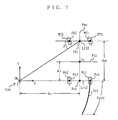
- FIG. 7 shows four wheels of the vehicle Vusr (not shown) , that is, a front-right wheel Wf1 , a front-left wheel Wf2, a rear-right wheel Wr1 , and a rear-left wheel Wr2.
- the distance between a rotation center Pf1 of the front-right wheel Wf1 and a rotation center Pr1 of the rear-right wheel Wr1 is denoted by Dwb. That is, the distance Dwb is a wheel base of the vehicle Vusr, and is an eigenvalue and known quantity for the vehicle Vusr.
- FIG. 7 also shows line segments Lr12 and Lr12 , the longitudinal median plane Fwc, and the lateral median plane Flc .
- the line segment Lf12 connects the rotation center Pf1 and a rotation center Pf2 of the front-left wheel Wf2, while the line segment Lr12 connects the rotation center Pr1 and a rotation center Pr2 of the rear-left wheel Wr2 .
- Those line segments Lf12 and Lr12 are both eigenvalues and known in length. In this embodiment, for convenience, those line segments Lf12 and Lr12 are presumably equal in length of Dr12.
- FIG. 7 also shows, for convenience, a second 3D coordinate system CSb , including three axes of X, Y, and Z.
- the vehicle Vusr circles around a point Ob which is observed on a line extended from the line segment Lr12 .
- the point Ob is the origin of the second 3D coordinate system CSb, and thus all of the axes of X, Y, and Z pass through the origin Ob .
- the X-axis includes the line segment Lr12
- the Y-axis is parallel to the longitudinal median plane Fwc
- the Z-axis is parallel to the vertical direction.
- the radius Rs is calculated by the following equation (1).
- the radius Rs is the distance from the point Ob to a midpoint Prc of the line segment Lr12 .
- Rs Dwb / tan ⁇
- the distance Dwb is a known value
- a steered angle ⁇ indicates at what angle the front wheels Wf1 and Wf2 are turned.
- the steered angle ⁇ is, as shown in FIG. 7, formed by a line connecting the point Ob and a midpoint Pfc of the line segment Lf12 , and a ray connecting the midpoint Pfc and the rotation center Pf2.
- the X coordinate of the rotation center Pr1 of the rear-right wheel Wr1 is Rs + Dr12/2, while the Y coordinate thereof is 0.
- the circle traceable by the rear-right wheel Wr1 , on the rotation center Pr1 , around the origin Ob can be expressed by the following equation (4).
- X 2 + Y 2 (Rs + Dr12/2) 2
- the predictive trajectory Tr1 is an arc in a predetermined length of Lprd starting from the rear-right wheel Wr1 .
- the rudder angle ⁇ is the only unknown value. It means substituting the rudder angle ⁇ stored in step S7 to the above equation (4) will find the predictive trajectory Tr1 of the rear-right wheel Wr1 .
- the circle traceable by the rear-left wheel Wr2, on the rotation center Pr2, around the origin Ob can be expressed by an equation, and thus the predictive trajectory Tr2 of the rear-left wheel Wr2 can be derived.
- step S8 the processor 1 adds a height value hprd to thus calculated predictive trajectories Tr1 and Tr2 so that predictive upper trajectories Tur1 and Tur2 are derived (step S9).
- the height hprd is preferably positive, and equal to or smaller than the height of the vehicle Vusr.
- the processor 1 produces a 3D predictive trajectory T3d of the vehicle Vusr.
- the 3D predictive trajectory T3d is a region enclosed by the predictive trajectories Tr1 and Tr2, and the predictive upper trajectories Tur1 and Tur2, and three-dimensionally indicates how the vehicle Vusr moves on the road surface Frd from now on.
- the processor 1 overlays thus calculated 3D predictive trajectory T3d onto the vehicle overlaid image Svhc on the frame memory (step S10).
- the resulting image is referred to as a display image Sdsp .
- the origin Oa of the first 3D coordinate system CSa is a point of intersection of the road surface Frd, the longitudinal median plane Fwc, and the lateral median plane Flc .
- the origin Oa is away from the origin Ob of the second 3D coordinate system Csb by Rs in the X-axis direction and ⁇ y in the Y-axis direction.
- ⁇ y denotes a distance from the midpoint Prc to the lateral median plane Flc , and is an eigenvalue (i.e., known quantity) of the vehicle Vusr.
- the processor 1 For conversion to the first 3D coordinate system CSa, the processor 1 translates both the predictive trajectory Tr1 and the predictive upper trajectory Tur1 by Rs in the X-axis direction and ⁇ y in the Y-axis direction.
- those predictive trajectory Tr1 and the predictive upper trajectory Tur1 after translation are respectively referred to as a translated predictive trajectory Tmr1 and a translated predictive upper trajectory Tmur1 .
- the translated predictive trajectory Tmr1 is expressed by the following equation (6) , and as shown in FIG. 8, extended in the direction of an arrow A2 from the rear-right wheel Wr1 as the vehicle Vusr (not shown) moves backward.
- the translated predictive upper trajectory Tmur1 is expressed by the following equation (7), and extended in the same direction as the translated predictive trajectory Tmr1 but away therefrom by the height hprd in the vertical direction.
- (X - Rs) 2 + (Y - ⁇ y) 2 (Rs + Dr12/2) 2
- (X - Rs) 2 + (Y - ⁇ y) 2 + (Z - hprd) 2 (Rs + Dr12/2) 2
- the processor 1 produces such translated predictive trajectory Tmr2 and translated predictive upper trajectory Tmur2 as shown in FIG. 8.
- the processor 1 samples n points (where n is a natural number being 2 or larger) from the translated predictive upper trajectory Tmur1 as sampling points Ps11 to Ps1n (FIG. 9 shows the sampling point Ps11 only).
- the sampling points are so taken as to be regular in interval from/to adjacent sampling points Ps1i and Ps1 (i+1) , where i is a natural number between 1 and ( n -1).
- the processor 1 projects the sampling points Ps11 to Ps1n on the road surface Frd (i.e., XY plane) from the virtual viewpoint Pvt1 , and calculates 3D coordinates for each of projected sampling points Ps11' to Ps1n' .
- FIG. 9 described in detail is a method of calculating 3D coordinates for those projected sampling points Ps11' to Ps1n' .
- Xs11 , Ys11, and hprd are, respectively, the X coordinate, Y coordinate, and Z coordinate of the sampling point Ps11 in the first 3D coordinate system Csa, and all known values.
- zv is the Z coordinate of the virtual viewpoint Pvt1
- t is a variable.
- the 3D coordinates of the projected sampling point Ps11' is calculated as (-zv ⁇ n1/n3, -zv ⁇ n2/n3, 0).
- the processor 1 calculates the 3D coordinates for each of the projected sampling points Ps12' to Ps1n' in the same manner.
- the processor 1 also samples n sampling points of Ps21 to Ps2n from the translated predictive upper trajectory Tmur2, and then calculates the 3D coordinates for each of projected sampling points Ps21' to Ps2n'.
- the processor 1 takes n sampling points of Psr11 to Psr1n from the predictive trajectory Tr1 , and Psr21 to Psr2n on the predictive trajectory Tr2.
- the processor 1 produces a rendering 3D predictive trajectory Tr3d, which is the one obtained by projecting the 3D predictive trajectory T3d on the road surface Frd .
- the rendering 3D predictive trajectory Tr3d is a region enclosed by the projected sampling points Ps11' to Ps1n', Ps21' to Ps2n' , and the sampling points Psr11 to Psr1n, and Psr21 to Psr2n.
- the processor 1 renders the rendering 3D predictive trajectory Tr3d on the vehicle overlaid image Svhc on the frame memory, and generates such display image Sdsp as shown in FIG. 10 (step S10). More specifically, the processor 1 first selects, from among all of the sampling points found on the rendering 3D predictive trajectory Tr3d, the projected sampling points Ps1i' and Ps1(i+1), Ps2i' and Ps2 (i+1) , and the sampling points Psr1i and Psr1(i+1), and Psr2i and Psr2(i+1) . With those selected sampling points, the processor 1 then renders a rectangular solid projected on the road surface Frd with the same scaling factor Fsc1 as above.
- the processor 1 then repeats the same processing until i changes from 1 to (n - 1).
- the rendering 3D predictive trajectory Tr3d is successfully rendered on the vehicle overlaid image Svhc .
- the rendering 3D predictive trajectory Tr3d in the drawing is extending from the rear wheels of the vehicle model image Smd.
- the rendering 3D predictive image Tr3d in the display image Sdsp is so rendered as to extend from the rear end of the vehicle model image Smd.
- the processor 1 then transfers the display image Sdsp on the frame memory to the display device 14 for display on its screen (step S11).
- the driver can check whether or not his/her current steering makes the vehicle Vusr fit into the parking space without hitting any object in a close range, or causing wheel stuck in a ditch.
- the display image Sdsp three-dimensionally shows the predictive trajectory of the vehicle Vusr . Therefore, the driver can also check whether or not the vehicle Vusr fits into the parking space without causing any part of the vehicle Vusr placed high up from the road surface Frd (e.g.,fender) to hit any object.
- Frd e.g.,fender
- step S12 the processor 1 determines whether now is the time to end the processing of FIG. 5 (step S12). To see whether to end the processing, as one example, the processor 1 checks whether the engine of the vehicle Vusr has been stopped. If stopped, the processor 1 determines that the vehicle Vusr is now in the parking space, and thus ends the processing of FIG. 5. If not yet, the procedure returns to step S2 to generate another display image Sdsp.
- the processor 1 calculates the rendering 3D predictive trajectory Trd3 based on the predictive trajectory Tr1 and the predictive upper trajectory Tur1 of the rear-right wheel Wr1 of the vehicle Vusr, and the predictive trajectory Tr2 and the predictive upper trajectory Tur2 of the rear-left wheel Wr2 .
- the processor 1 may render, in addition to the rendering 3D predictive trajectory Tr3d , another rendering 3D predictive trajectory Tr3d' as shown in FIG. 11.
- the rendering 3D predictive trajectory Tr3d' is the one derived based on a predictive trajectory and a predictive upper trajectory for the upper-right part Pc1 of the vehicle Vusr.
- the direction to which the steering wheel is turned is determined by whether the rudder angle ⁇ is positive or negative.
- the processor 1 may detect to which direction the steering wheel is now turned based on whether the rudder angle ⁇ is positive or negative, and with reference to the rear corner (the upper-right part Pc1 ) of the vehicle Vusr on the side opposite to the detected direction with respect to the heading direction, calculate the rendering 3D predictive trajectory Tr3d'.
- the processor 1 can calculate the rendering 3D predictive trajectory based on any arbitrary position in the space enclosed by the surface of the vehicle Vusr.
- the processor 1 generates the viewpoint-converted image Scvt from the surrounding images S1 to S8, and thereonto, overlays the vehicle model image Smd and the rendering 3D predictive trajectory Tr3d.
- the processor 1 may overlay the vehicle model image Smd and the rendering 3D predictive trajectory Tr3d onto the surrounding images S4 and S5 to generate the above display image Sdsp.
- image capture devices 5 to 12 are fixedly placed in the vehicle Vusr. However, at least one image capture device will do as long as capturing a view image extending toward the rear of the vehicle Vusr.
- the predictive trajectories Tr1 and Tr2 are both calculated based on the rudder angle ⁇ .
- the wheel speed may be considered.
- FIG. 12 described next is another drive assistant device Uast2 incorporating a rendering device Urnd2, which is an exemplary modification of the rendering device Urnd1 .
- the rendering device Urnd2 compared with the rendering device Urnd1 , includes program memory 21 instead of the program memory 2. This is the only structural difference therebetween, and thus any component appeared in the rendering device Urnd1 is under the same reference numeral, and not described again.
- the program memory 21 is typically ROM, and stores a program PGb for defining the processing procedure in the processor 1, and the vehicle model data Dmd described above with reference to FIG. 3.
- the drive assistant device Uast2 is placed in the vehicle Vusr as is the drive assistant device Uast1.
- the drive assistant device Uast2 is additionally provided with a gear sensor 22, and the rendering device Urnd2 instead of the rendering device Urnd1 .
- the driver moves a gearshift to shift gears to an upper or lower.
- the gear sensor 22 detects in what gear the gearshift is, and the detected gear ⁇ is transmitted to the processor 1.
- the input device 4 is, typically, operated by the driver when he/she parks the vehicle Vusr.
- the input device 4 generates a start instruction signal Istr, and transmits the start instruction signal Istr to the processor 1.
- the processor 1 then responsively starts executing the program PGb.
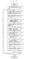
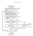
- FIG. 13 a flowchart of FIG. 13 for the processing procedure in the processor 1 described in the program PGb.
- the processor 1 first reads the vehicle model data Dmd from the program memory 21 to the working area 3 (step S21).
- the processor 1 generates a gear detection instruction signal Isdtc , and transmits the gear detection instruction signal Isdtc to the gear sensor 22 (step S22).
- the gear detection instruction signal Isdtc is a signal for instructing the gear sensor 22 to detect the gear ⁇ .
- the gear sensor 22 accordingly detects the gear ⁇ , and transmits the detected gear ⁇ to the processor 1 (step S23).
- the processor 1 determines whether the vehicle Vusr is going to move forward or backward (step S24). In detail, when the received gear ⁇ indicates other than Neutral and Reverse, the processor 1 determines as the vehicle Vusr moving forward.
- the processor 1 determines as the vehicle Vusr is moving backward.
- the procedure repeats step S22 again (not shown in FIG. 13).
- the processor 1 executes a rearward mode (step S25).
- the processor 1 derives, as described in the first embodiment, the predictive trajectories indicating how the rear wheels of the vehicle Vusr will move on the road surface Frd, and the predictive upper trajectories with the height added thereto. Then, based on those predictive trajectories and predictive upper trajectories, the processor 1 generates such display image Sdsp as shown in FIG. 10. The display image Sdsp is then transferred to the display device 14 for display thereon.
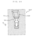
- the processor 1 executes a forward mode (step S26). Unlike the rearward mode, the wheels trailed along in the forward mode for the predictive trajectories are the front wheels of the vehicle Vusr. This is rather a conspicuous difference.
- the processor 1 calculates the predictive trajectories indicating how the front wheels of the vehicle Vusr will move on the road surface Frd , and the predictive upper trajectories with the height added thereto. Then, based on those predictive trajectories and predictive upper trajectories, the processor 1 renders a rendering 3D predictive trajectory Tr3df, as shown in FIG. 14, and then generates a display image Sdspf.
- the rendering 3D predictive trajectory Tr3df is so rendered on the road surface Frd as to extend from the front end of the vehicle model image Smd to the heading direction of an arrow A3.
- the display image Sdspf is transferred to the display device 14 for display thereon.
- step S25 or S26 the processor 1 determines whether now is the time to end the processing of FIG. 13 with the method described in step S12 of FIG. 5 (step S27). If the processor 1 determines that the vehicle Vusr is now in the parking space, this is the end of the processing of FIG. 13. If determined not yet, the procedure returns to step S22 to repeat the same processing.
- the processor 1 automatically determines whether the vehicle Vusr is now going to move forward or backward based on the gear ⁇ received from the gear sensor 22, and generates a display image meeting the driver's needs. Accordingly, the drive assistant device Uast2 is considered more driver-friendly than the drive assistant device Uast1.
- FIG. 15 is a block diagram showing the hardware structure of a rendering device Urnd3 according to a second embodiment of the present invention.
- the rendering device Urnd3 includes program memory 31 instead of the program memory 2. This is the only structural difference therebetween, and thus any component appeared in the rendering device Urnd1 is under the same reference numeral, and not described again.
- the program memory 31 is typically ROM, and stores a program PGc for defining the processing procedure in the processor 1, and the vehicle model data Dmd described above with reference to FIG. 3.
- the drive assistant device Uast3 is placed in the vehicle Vusr of FIG. 2 as is the drive assistant device Uast1 .
- incorporated in the drive assistant device Uast3 is not the rendering device Urnd1 but the rendering device Urnd2, and at least two wheel speed sensors 32 and 33 are further provided therein.
- FIG. 15 shows only four image capture devices 5, 6, 11, and 12 due to limited space, but the drive assistant device Uast3 actually carries 8 image capture devices 5 to 12 as the drive assistant device Uast1.
- the wheel speed sensor 32 and 33 detect a wheel speed Vr of the rear-right wheel of the vehicle Vusr and a wheel speed V1 of the rear-left wheel, respectively, and transmits those wheel speeds Vr and V1 to the processor 1.
- FIG. 16 is a flowchart showing the processing procedure in the processor 1 described in the program PGc .
- the flowchart of FIG. 16 includes steps S31 to S36 as alternatives to steps S8 to S11. This is the only difference therebetween, and thus any step appeared in FIG. 5 is under the same step number and not described again.
- step S7 the frame memory stores such vehicle overlaid image Svhc as shown in FIG. 6B, and the working area 3 stores the rudder angle ⁇ .
- the processor 1 After step S7, the processor 1 generates a wheel speed detection instruction signal Iwdtc, and transmits the wheel speed detection instruction signal Iwdtc to both the wheel speed sensors 32 and 33 (step S31).
- the wheel speed detection instruction signal Iwdtc is a signal for instructing the wheel speed sensors 32 and 33 to detect the wheel speeds Vr and Vl.
- the wheel speed sensors 32 and 33 thus responsively detect the wheel speeds Vr and Vl, and store the detected wheel speeds Vr and V1 in the working area 3 (step S32).
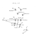
- step S33 the processor 1 specifies each current position of the wheels of the vehicle Vusr (step S33).
- FIG. 17 shows the four wheels of the vehicle Vusr (not shown) on the road surface Frd, that is, the front-right wheel Wf1 , the front-left wheel Wf2, the rear-right wheel Wr1 , and the rear-left wheel Wr2.
- FIG. 7 also shows a line segment Lr12 connecting a rotation center Pr1 of the rear-right wheel Wr1 and a rotation center Pr2 of the rear-left wheel Wr2 . Also, the midpoint of the line segment Lr12 is Prc.
- the midpoint Prc starts moving from a point Ct as the vehicle Vusr moves backward.
- the positions of the rotation centers Pr1 and Pr2 are referred to as, respectively, an initial position Pr1t of the rear-right wheel Wr1 and an initial position Pr2t of the right-left wheel Wr2 .
- the positions of rotation centers Pf1 and Pf2 of the front-right wheel Wf1 and front-left wheel Wf2 are referred to as, respectively, an initial position Pf1t and an initial position Pf2t .
- Vr and Vl denote the wheel speeds of the rear-right wheel Wr1 and the rear-left wheel Wr2, respectively.
- Rs is a radius of a circle traceable by the midpoint Prc as described by referring to FIG. 7.
- ⁇ is a rotation angle of the midpoint Prc , and formed by a line segment Ct Ob and a line segment Ob Ct+1 .
- Ob is a center of the circle traceable by the midpoint Prc as described above.
- a 2D coordinate system Csc including axes of X and Y is defined.
- the X-axis is set to direct toward the rotation center Pf1 of the front-right wheel Wf1 , while the Y-axis toward the rotation center Pr2 from the same rotation center Pr1.
- a vector Trc from the point Ct to Ct+1 is expressed by the following equation (15) .
- the processor 1 stores the resulting position Pr1(t+1) of the rear-right wheel Wr1, the position Pr2(t+1) of the rear-left wheel Wr2, the position Pf1 (t+1) of the front-right wheel Wf1, and the position Pf2 (t+1) of the front-left wheel Wf2 to the working area 3 (step S34).
- the procedure returns to step S2 from step S12 in some cases, and if so, step S34 is repeatedly carried out until the vehicle Vusr is parked.
- step S34 those calculated positions of Pr1(t+1) , Pr2(t+1), Pf1(t+1) , and Pf2(t+1) are not deleted by those newly calculated, but stored form number of times (where m is a natural number being 1 or larger) in the working area 3.
- the processor 1 renders, on the vehicle overlaid image Svhc on the frame memory, a trail MTr1 of the rear-right wheel Wr1 , a trail MTr2 of the rear-left wheel Wr2, a trail MTf1 of the front-right wheel Wf1 , and a trail MTf2 of the front-left wheel Wf2.
- the resulting image is a display image Sdspm as shown in FIG. 18 (step S35).
- the processor 1 connects m points of Pr1 (t+1) in the working area 3 so that the trail MTr1 is generated.
- the trail MTr1 shows previous movement of the rear-right wheel Wr1 of the vehicle Vusr on the road surface Frd.
- the processor 1 then renders, in the scaling factor Fsc1 , thus generated trail MTr1 from the rear-right wheel part of the vehicle model image Smd to the inverse direction of the heading direction of the vehicle Vusr.
- the processor 1 renders the trails MTr2, MTf1 , and MTf2.
- FIG. 18 shows, for convenience, the trails MTr1, MTr2, MTf1, and MTf2 extending from the wheel positions of the vehicle model image Smd.
- the trails MTr1, MTr2, MTf1 , and MTf2 in the display image Sdspm are so rendered as to extend from the front end of the vehicle model image Smd.
- the processor 1 then transfers the display image Sdspm on the frame memory to the display device 14 for display thereon (step S36).
- parking especially parallel parking, the driver may have a hard time to park the vehicle Vusr if the initial position thereof is not appropriate.
- the driver can see which trails so far tried but failed. Therefore, the driver can recognize which initial position so far failed him/her, and he/she can try more appropriate initial position to park the vehicle Vusr.
- step S12 the processor 1 determines whether now is the time to end the processing of FIG. 16 (step S12). If the processor 1 determines that the vehicle Vusr is now parked, this is the end of the processing of FIG. 16. If not yet, the procedure returns to step S2 to generate another display image Sdspm.
- the wheel speed sensors 32 and 33 are incorporated in the drive assistant device Uast3 to produce the trails MTr1, MTr2, MTf1, and MTf2 .
- any type of sensor will do as long as detecting the speed of the vehicle Vusr.
- the programs PGa to PGc are stored in the rendering devices Urnd1 to Urnd3, respectively.
- those programs PGa to PGc may be distributed in a recording medium typified by CD-ROM, or over a communications network such as the Internet.
Abstract
Description
Claims (15)
- A rendering device (Urndl, Urnd2) for generating a display image for drive assistance, said device comprising:a first generation part (1) for generating a surrounding image corresponding to an area surrounding the vehicle; anda reception part (1) for receiving a current rudder angle from a rudder angle sensor placed in said vehicle;a calculation part (1) for calculating, based on the rudder angle received by said reception part, a three-dimensional predictive trajectory of said vehicle; anda second generation part (1) for generating the display image showing the three-dimensional predictive trajectory calculated in said calculation part rendered on the surrounding image generated by said first generation part.
- The rendering device according to claim 1, wherein said calculation part calculates said three-dimensional predictive trajectory with reference to a wheel position of said vehicle.
- The rendering device according to claim 1, wherein said calculation part calculates said three-dimensional predictive trajectory with reference to a point on a surface of said vehicle farthest from a longitudinal median plane of the vehicle.
- The rendering device according to claim 1, wherein when said vehicle is moving backward, said calculation part calculates the three-dimensional predictive trajectory extending toward the back of the vehicle.
- The rendering device according to claim 1, wherein when said vehicle is moving forward, said calculation part calculates the three-dimensional predictive trajectory extending toward the front of the vehicle.
- The rendering device according to claim 1, wherein said calculation part calculates, by referring to the rudder angle received from said rudder angle sensor, the three-dimensional predictive trajectory with reference to a corner on the opposite side to the rudder angle and on the rear side of the vehicle with respect to a heading direction.
- The rendering device according to claim 1, wherein a gear sensor is provided in said vehicle for detecting a current gear thereof, andsaid device further includes a determination part (1) for determining whether said vehicle is moving forward or backward based on the gear provided by said gear sensor, andsaid calculation partcalculates, when said determination part determines that said vehicle is moving forward, the three-dimensional predictive trajectory extending in a forward direction, andcalculates, when said determination part determines that said vehicle is moving backward, the three-dimensional predictive trajectory extending in a backward direction.
- A rendering device (Urnd3) for generating a display image for drive assistance, said device comprising:a first generation part (1) for generating a surrounding image corresponding to an area surrounding the vehicle;a calculation part (1) for calculating a trail of said vehicle; anda second generation part (1) for generating the display image showing the trail calculated in said calculation part rendered on the surrounding image received by said first generation part.
- The rendering device according to claim 8, further comprising:a first reception part (1) for receiving a current rudder angle of said vehicle from a rudder angle sensor placed in the vehicle; anda second reception part (1) for receiving a wheel speed of each wheel of said vehicle from a wheel speed sensor placed in the vehicle, andsaid calculation part calculates the trail of said vehicle based on the rudder angle received by said first reception part and the wheel speeds received by said second reception part.
- A rendering method for generating a display image for drive assistance, said method comprising:a first generation step (S5) of generating a surrounding image corresponding to an area surrounding the vehicle; anda reception step (S7) of receiving a current rudder angle from a rudder angle sensor placed in said vehicle;a calculation step (S8, S9) of calculating a three-dimensional predictive trajectory of said vehicle based on the rudder angle received in said reception step; anda second generation step (S10) of generating the display image showing the three-dimensional predictive trajectory calculated in said calculation step rendered on the surrounding image received in said first generation step.
- A rendering method for generating a display image for drive assistance, said method comprising:a first generation step (S5) of receiving a surrounding image corresponding to an area surrounding the vehicle; anda calculation step (S33) of calculating a trail of said vehicle; anda second generation step (S35) of generating the display image showing the trail calculated in said calculation step rendered on the surrounding image received in said first reception step.
- A recording medium on which a program for generating a display image for drive assistance is recorded, said program comprising:a first generation step (S5) of generating a surrounding image corresponding to an area surrounding the vehicle; anda reception step (S7) of receiving a current rudder angle from a rudder angle sensor placed in said vehicle;a calculation step (S8, S9) of calculating, based on the rudder angle received in said reception step, a three-dimensional predictive trajectory indicating of said vehicle; anda second generation step (S10) of generating the display image showing the three-dimensional predictive trajectory calculated in said calculation step rendered on the surrounding image received in said first reception step.
- A recording medium on which a program for generating a display image for drive assistance is recorded, said program comprising:a first generation step (S5) of generating a surrounding image corresponding to an area surrounding the vehicle; anda calculation step (S33) calculating a trail of said vehicle; anda second generation step (S35) of generating the display image showing the trail calculated in said calculation step rendered on the surrounding image received in said first reception step.
- A program for generating a display image for drive assistance is recorded, comprising:a first generation step (S5) of generating a surrounding image corresponding to an area surrounding the vehicle; anda reception step (S7) of receiving a current rudder angle from a rudder angle sensor placed in said vehicle;a calculation step (S8, S9) of calculating, based on the rudder angle received in said reception step, a three-dimensional predictive trajectory of said vehicle; anda second generation step (S10) of generating the display image showing the three-dimensional predictive trajectory calculated in said calculation step rendered on the surrounding image received in said first reception step.
- A program for generating a display image for drive assistance is recorded, comprising:a first generation step (S5) of generating a surrounding image corresponding an area surrounding the vehicle; anda calculation step (S33) of calculating a trail of said vehicle; anda second generation step (S35) of generating the display image showing the trail calculated in said calculation step rendered on the surrounding image received in said first reception step.
Applications Claiming Priority (2)
| Application Number | Priority Date | Filing Date | Title |
|---|---|---|---|
| JP2000152381 | 2000-05-24 | ||
| JP2000152381 | 2000-05-24 |
Publications (2)
| Publication Number | Publication Date |
|---|---|
| EP1158803A2 true EP1158803A2 (en) | 2001-11-28 |
| EP1158803A3 EP1158803A3 (en) | 2003-12-10 |
Family
ID=18657811
Family Applications (2)
| Application Number | Title | Priority Date | Filing Date |
|---|---|---|---|
| EP01112379A Withdrawn EP1158803A3 (en) | 2000-05-24 | 2001-05-21 | Rendering device for generating a display image |
| EP01112420A Withdrawn EP1158804A3 (en) | 2000-05-24 | 2001-05-21 | Rendering device for generating a display image |
Family Applications After (1)
| Application Number | Title | Priority Date | Filing Date |
|---|---|---|---|
| EP01112420A Withdrawn EP1158804A3 (en) | 2000-05-24 | 2001-05-21 | Rendering device for generating a display image |
Country Status (4)
| Country | Link |
|---|---|
| US (2) | US7304651B2 (en) |
| EP (2) | EP1158803A3 (en) |
| KR (1) | KR100425383B1 (en) |
| CN (1) | CN100386223C (en) |
Cited By (2)
| Publication number | Priority date | Publication date | Assignee | Title |
|---|---|---|---|---|
| EP1696669A1 (en) * | 2005-02-24 | 2006-08-30 | Aisin Seiki Kabushiki Kaisha | Vehicle surrounding monitoring device |
| FR2890614A1 (en) * | 2005-09-14 | 2007-03-16 | Renault Sas | Computerised system for aiding reverse manoeuvring of motor vehicle has transparent display on rear screen showing vehicle dimensions and optimum trajectory |
Families Citing this family (93)
| Publication number | Priority date | Publication date | Assignee | Title |
|---|---|---|---|---|
| EP1158803A3 (en) * | 2000-05-24 | 2003-12-10 | Matsushita Electric Industrial Co., Ltd. | Rendering device for generating a display image |
| US6825779B2 (en) * | 2000-06-30 | 2004-11-30 | Matsushita Electric Industrial Co., Ltd. | Rendering device |
| JP4156214B2 (en) * | 2001-06-13 | 2008-09-24 | 株式会社デンソー | Vehicle periphery image processing apparatus and recording medium |
| DE10140146A1 (en) * | 2001-08-16 | 2003-02-27 | Philips Corp Intellectual Pty | Arrangement for vehicle position assignment of wheels of a vehicle |
| JP3947375B2 (en) * | 2001-08-24 | 2007-07-18 | アイシン精機株式会社 | Parking assistance device |
| US6916584B2 (en) * | 2002-08-01 | 2005-07-12 | Molecular Imprints, Inc. | Alignment methods for imprint lithography |
| WO2005050543A1 (en) * | 2003-11-13 | 2005-06-02 | Honda Motor Co., Ltd. | Adaptive probabilistic visual tracking with incremental subspace update |
| US7219766B2 (en) * | 2004-06-29 | 2007-05-22 | Deuer Joseph F | Mid-span fall protection system |
| US7460953B2 (en) * | 2004-06-30 | 2008-12-02 | Navteq North America, Llc | Method of operating a navigation system using images |
| US8751156B2 (en) | 2004-06-30 | 2014-06-10 | HERE North America LLC | Method of operating a navigation system using images |
| US20060002590A1 (en) * | 2004-06-30 | 2006-01-05 | Borak Jason M | Method of collecting information for a geographic database for use with a navigation system |
| US7369682B2 (en) * | 2004-07-09 | 2008-05-06 | Honda Motor Co., Ltd. | Adaptive discriminative generative model and application to visual tracking |
| DE102005004394B4 (en) * | 2005-01-31 | 2012-09-06 | Continental Automotive Gmbh | Return assistant |
| US7451041B2 (en) * | 2005-05-06 | 2008-11-11 | Facet Technology Corporation | Network-based navigation system having virtual drive-thru advertisements integrated with actual imagery from along a physical route |
| US7623731B2 (en) * | 2005-06-20 | 2009-11-24 | Honda Motor Co., Ltd. | Direct method for modeling non-rigid motion with thin plate spline transformation |
| DE112006001864T5 (en) * | 2005-07-14 | 2008-06-05 | GM Global Technology Operations, Inc., Detroit | System for monitoring the vehicle environment from a remote perspective |
| FR2891934B1 (en) * | 2005-10-12 | 2008-01-18 | Valeo Electronique Sys Liaison | DEVICE FOR PROCESSING VIDEO DATA FOR A MOTOR VEHICLE |
| US8535791B2 (en) * | 2006-06-30 | 2013-09-17 | The University Of Akron | Aligned carbon nanotube-polymer materials, systems and methods |
| GB2447672B (en) * | 2007-03-21 | 2011-12-14 | Ford Global Tech Llc | Vehicle manoeuvring aids |
| KR100974704B1 (en) * | 2007-04-30 | 2010-08-06 | 현대자동차주식회사 | Parking Guidance Method for Vehicle |
| CA2692277A1 (en) * | 2007-07-03 | 2009-01-08 | J. Edward Ramsey | Trailer hitch alignment device and method |
| JP5120880B2 (en) * | 2007-10-15 | 2013-01-16 | アルパイン株式会社 | Image processing apparatus and image processing method |
| DE102008034594B4 (en) * | 2008-07-25 | 2021-06-24 | Bayerische Motoren Werke Aktiengesellschaft | Method and information system for informing an occupant of a vehicle |
| JP5420216B2 (en) * | 2008-09-16 | 2014-02-19 | 本田技研工業株式会社 | Vehicle perimeter monitoring device |
| JP2010093605A (en) * | 2008-10-09 | 2010-04-22 | Sanyo Electric Co Ltd | Maneuvering assisting apparatus |
| KR100966288B1 (en) * | 2009-01-06 | 2010-06-28 | 주식회사 이미지넥스트 | Around image generating method and apparatus |
| US8935055B2 (en) * | 2009-01-23 | 2015-01-13 | Robert Bosch Gmbh | Method and apparatus for vehicle with adaptive lighting system |
| JP5102795B2 (en) * | 2009-03-13 | 2012-12-19 | パナソニック株式会社 | Driving support display device |
| JP5439890B2 (en) * | 2009-03-25 | 2014-03-12 | 富士通株式会社 | Image processing method, image processing apparatus, and program |
| KR100956858B1 (en) * | 2009-05-19 | 2010-05-11 | 주식회사 이미지넥스트 | Sensing method and apparatus of lane departure using vehicle around image |
| US8502860B2 (en) * | 2009-09-29 | 2013-08-06 | Toyota Motor Engineering & Manufacturing North America (Tema) | Electronic control system, electronic control unit and associated methodology of adapting 3D panoramic views of vehicle surroundings by predicting driver intent |
| DE102010048185B4 (en) * | 2010-10-13 | 2021-10-28 | Wirtgen Gmbh | Self-propelled construction machine |
| US9513103B2 (en) | 2011-04-19 | 2016-12-06 | Ford Global Technologies, Llc | Hitch angle sensor assembly |
| US9506774B2 (en) | 2011-04-19 | 2016-11-29 | Ford Global Technologies, Llc | Method of inputting a path for a vehicle and trailer |
| US10196088B2 (en) | 2011-04-19 | 2019-02-05 | Ford Global Technologies, Llc | Target monitoring system and method |
| US9723274B2 (en) | 2011-04-19 | 2017-08-01 | Ford Global Technologies, Llc | System and method for adjusting an image capture setting |
| US9969428B2 (en) | 2011-04-19 | 2018-05-15 | Ford Global Technologies, Llc | Trailer backup assist system with waypoint selection |
| US9500497B2 (en) | 2011-04-19 | 2016-11-22 | Ford Global Technologies, Llc | System and method of inputting an intended backing path |
| US9937953B2 (en) | 2011-04-19 | 2018-04-10 | Ford Global Technologies, Llc | Trailer backup offset determination |
| US9926008B2 (en) | 2011-04-19 | 2018-03-27 | Ford Global Technologies, Llc | Trailer backup assist system with waypoint selection |
| US9683848B2 (en) | 2011-04-19 | 2017-06-20 | Ford Global Technologies, Llc | System for determining hitch angle |
| US9854209B2 (en) | 2011-04-19 | 2017-12-26 | Ford Global Technologies, Llc | Display system utilizing vehicle and trailer dynamics |
| JP5124671B2 (en) * | 2011-06-07 | 2013-01-23 | 株式会社小松製作所 | Work vehicle perimeter monitoring device |
| JP5845794B2 (en) * | 2011-10-11 | 2016-01-20 | 富士通株式会社 | Moving locus interpolation apparatus, moving locus interpolation method, and program |
| EP2581268B2 (en) * | 2011-10-13 | 2019-09-11 | Harman Becker Automotive Systems GmbH | Method of controlling an optical output device for displaying a vehicle surround view and vehicle surround view system |
| WO2013086249A2 (en) * | 2011-12-09 | 2013-06-13 | Magna Electronics, Inc. | Vehicle vision system with customized display |
| JP5811260B2 (en) * | 2012-02-16 | 2015-11-11 | トヨタ自動車株式会社 | Vehicle height estimation device and vehicle height estimation method |
| DE102012202916A1 (en) * | 2012-02-27 | 2013-08-29 | Robert Bosch Gmbh | Method and device for operating a vehicle |
| KR101376211B1 (en) * | 2012-06-01 | 2014-03-21 | 현대모비스 주식회사 | Image composing apparatus of around view monitor system for changing view mode easily and method thereof |
| JP6079131B2 (en) * | 2012-10-25 | 2017-02-15 | 富士通株式会社 | Image processing apparatus, method, and program |
| US9511799B2 (en) | 2013-02-04 | 2016-12-06 | Ford Global Technologies, Llc | Object avoidance for a trailer backup assist system |
| US9592851B2 (en) | 2013-02-04 | 2017-03-14 | Ford Global Technologies, Llc | Control modes for a trailer backup assist system |
| KR101510336B1 (en) * | 2013-11-14 | 2015-04-07 | 현대자동차 주식회사 | Device for inspecting driver assistance system of vehicle |
| KR101510338B1 (en) * | 2013-11-22 | 2015-04-07 | 현대자동차 주식회사 | Device for inspecting lane departure warning system of vehicle |
| US9963004B2 (en) | 2014-07-28 | 2018-05-08 | Ford Global Technologies, Llc | Trailer sway warning system and method |
| US9517668B2 (en) | 2014-07-28 | 2016-12-13 | Ford Global Technologies, Llc | Hitch angle warning system and method |
| US10112537B2 (en) | 2014-09-03 | 2018-10-30 | Ford Global Technologies, Llc | Trailer angle detection target fade warning |
| US10399495B1 (en) * | 2014-09-05 | 2019-09-03 | United Services Automobile Association (Usaa) | Systems and methods for indicating proximity conditions for a vehicle |
| US9533683B2 (en) | 2014-12-05 | 2017-01-03 | Ford Global Technologies, Llc | Sensor failure mitigation system and mode management |
| US9522677B2 (en) | 2014-12-05 | 2016-12-20 | Ford Global Technologies, Llc | Mitigation of input device failure and mode management |
| US9607242B2 (en) | 2015-01-16 | 2017-03-28 | Ford Global Technologies, Llc | Target monitoring system with lens cleaning device |
| US9522699B2 (en) | 2015-02-05 | 2016-12-20 | Ford Global Technologies, Llc | Trailer backup assist system with adaptive steering angle limits |
| US9616923B2 (en) | 2015-03-03 | 2017-04-11 | Ford Global Technologies, Llc | Topographical integration for trailer backup assist system |
| US9804022B2 (en) | 2015-03-24 | 2017-10-31 | Ford Global Technologies, Llc | System and method for hitch angle detection |
| US9849864B2 (en) | 2015-07-31 | 2017-12-26 | Ford Global Technologies, Llc | Vehicle parking assist system |
| CN105128760B (en) * | 2015-08-27 | 2018-10-16 | 惠州华阳通用电子有限公司 | Backing track plotting method and device |
| US9896130B2 (en) | 2015-09-11 | 2018-02-20 | Ford Global Technologies, Llc | Guidance system for a vehicle reversing a trailer along an intended backing path |
| US9981656B2 (en) | 2015-10-13 | 2018-05-29 | Ford Global Technologies, Llc | Vehicle parking assist system |
| US10384607B2 (en) | 2015-10-19 | 2019-08-20 | Ford Global Technologies, Llc | Trailer backup assist system with hitch angle offset estimation |
| US10611407B2 (en) | 2015-10-19 | 2020-04-07 | Ford Global Technologies, Llc | Speed control for motor vehicles |
| US9836060B2 (en) | 2015-10-28 | 2017-12-05 | Ford Global Technologies, Llc | Trailer backup assist system with target management |
| US10328933B2 (en) | 2015-10-29 | 2019-06-25 | Ford Global Technologies, Llc | Cognitive reverse speed limiting |
| CN106683037A (en) * | 2015-11-06 | 2017-05-17 | 阿里巴巴集团控股有限公司 | Method and equipment for three-dimensional visualized movement of track data |
| US10017115B2 (en) | 2015-11-11 | 2018-07-10 | Ford Global Technologies, Llc | Trailer monitoring system and method |
| US9934572B2 (en) | 2015-12-17 | 2018-04-03 | Ford Global Technologies, Llc | Drawbar scan solution for locating trailer hitch point |
| US9610975B1 (en) | 2015-12-17 | 2017-04-04 | Ford Global Technologies, Llc | Hitch angle detection for trailer backup assist system |
| US9798953B2 (en) | 2015-12-17 | 2017-10-24 | Ford Global Technologies, Llc | Template matching solution for locating trailer hitch point |
| US10155478B2 (en) | 2015-12-17 | 2018-12-18 | Ford Global Technologies, Llc | Centerline method for trailer hitch angle detection |
| US9827818B2 (en) | 2015-12-17 | 2017-11-28 | Ford Global Technologies, Llc | Multi-stage solution for trailer hitch angle initialization |
| US10005492B2 (en) | 2016-02-18 | 2018-06-26 | Ford Global Technologies, Llc | Trailer length and hitch angle bias estimation |
| US10112646B2 (en) | 2016-05-05 | 2018-10-30 | Ford Global Technologies, Llc | Turn recovery human machine interface for trailer backup assist |
| JP6555195B2 (en) * | 2016-06-13 | 2019-08-07 | 株式会社デンソー | Image generation device |
| US10106193B2 (en) | 2016-07-01 | 2018-10-23 | Ford Global Technologies, Llc | Enhanced yaw rate trailer angle detection initialization |
| US10046800B2 (en) | 2016-08-10 | 2018-08-14 | Ford Global Technologies, Llc | Trailer wheel targetless trailer angle detection |
| US10222804B2 (en) | 2016-10-21 | 2019-03-05 | Ford Global Technologies, Llc | Inertial reference for TBA speed limiting |
| US10684625B2 (en) * | 2017-08-30 | 2020-06-16 | Robert Bosch Gmbh | Automated parking for virtual parking spot |
| US10710585B2 (en) | 2017-09-01 | 2020-07-14 | Ford Global Technologies, Llc | Trailer backup assist system with predictive hitch angle functionality |
| US10744941B2 (en) | 2017-10-12 | 2020-08-18 | Magna Electronics Inc. | Vehicle vision system with bird's eye view display |
| US11521298B2 (en) * | 2018-09-10 | 2022-12-06 | Lumileds Llc | Large LED array with reduced data management |
| US11077795B2 (en) | 2018-11-26 | 2021-08-03 | Ford Global Technologies, Llc | Trailer angle detection using end-to-end learning |
| US10829046B2 (en) | 2019-03-06 | 2020-11-10 | Ford Global Technologies, Llc | Trailer angle detection using end-to-end learning |
| US11600181B2 (en) * | 2019-03-28 | 2023-03-07 | Honda Motor Co., Ltd. | Saddle-riding type vehicle |
| CN113525232A (en) * | 2020-04-16 | 2021-10-22 | 上海途擎微电子有限公司 | Method for forming and displaying vehicle reversing auxiliary line, vehicle, equipment and storage medium |
Citations (1)
| Publication number | Priority date | Publication date | Assignee | Title |
|---|---|---|---|---|
| JP2000067395A (en) | 1998-08-26 | 2000-03-03 | Nissan Motor Co Ltd | Parking guiding device |
Family Cites Families (36)
| Publication number | Priority date | Publication date | Assignee | Title |
|---|---|---|---|---|
| JPS6414700A (en) | 1987-07-08 | 1989-01-18 | Aisin Aw Co | Device for displaying prospective track of vehicle |
| US5163095A (en) * | 1988-04-22 | 1992-11-10 | Toa Medical Electronics Co., Ltd. | Processor for extracting and memorizing cell images, and method of practicing same |
| US5065447A (en) * | 1989-07-05 | 1991-11-12 | Iterated Systems, Inc. | Method and apparatus for processing digital data |
| JP2901112B2 (en) * | 1991-09-19 | 1999-06-07 | 矢崎総業株式会社 | Vehicle periphery monitoring device |
| US5670935A (en) * | 1993-02-26 | 1997-09-23 | Donnelly Corporation | Rearview vision system for vehicle including panoramic view |
| JP2799375B2 (en) * | 1993-09-30 | 1998-09-17 | 本田技研工業株式会社 | Anti-collision device |
| JPH07248821A (en) | 1994-03-10 | 1995-09-26 | Fujitsu Ltd | Line tracking device |
| JPH0850899A (en) | 1994-05-30 | 1996-02-20 | Sanyo Electric Co Ltd | Cell for solid electrolyte fuel cell |
| JP3395393B2 (en) | 1994-08-05 | 2003-04-14 | 日産自動車株式会社 | Vehicle periphery display device |
| JP3475507B2 (en) * | 1994-08-08 | 2003-12-08 | 日産自動車株式会社 | Ambient monitoring device for vehicles |
| JPH0935196A (en) | 1995-07-17 | 1997-02-07 | Mitsubishi Electric Corp | Periphery monitoring device and method for vehicle |
| US6507025B1 (en) * | 1995-10-23 | 2003-01-14 | Science Applications International Corporation | Density detection using real time discrete photon counting for fast moving targets |
| US5742141A (en) * | 1996-06-04 | 1998-04-21 | Ford Motor Company | Semi-autonomous parking control system for a vehicle providing tactile feedback to a vehicle operator |
| US5680123A (en) * | 1996-08-06 | 1997-10-21 | Lee; Gul Nam | Vehicle monitoring system |
| JP3711705B2 (en) * | 1996-10-15 | 2005-11-02 | いすゞ自動車株式会社 | Vehicle rear view support device |
| US5995903A (en) * | 1996-11-12 | 1999-11-30 | Smith; Eric L. | Method and system for assisting navigation using rendered terrain imagery |
| JPH10257482A (en) | 1997-03-13 | 1998-09-25 | Nissan Motor Co Ltd | Vehicle surrounding condition display device |
| JP3284917B2 (en) | 1997-03-17 | 2002-05-27 | 三菱自動車工業株式会社 | Perimeter recognition device for vehicles |
| US6049171A (en) * | 1998-09-18 | 2000-04-11 | Gentex Corporation | Continuously variable headlamp control |
| JPH1155656A (en) | 1997-08-06 | 1999-02-26 | Matsushita Electric Ind Co Ltd | Device for monitoring side of vehicle |
| JPH1178692A (en) * | 1997-09-03 | 1999-03-23 | Nissan Motor Co Ltd | Image display device for vehicle |
| JP3528548B2 (en) * | 1997-11-18 | 2004-05-17 | トヨタ自動車株式会社 | Vehicle moving image processing method and vehicle moving image processing device |
| JP2986439B2 (en) * | 1998-01-12 | 1999-12-06 | 松下電器産業株式会社 | Vehicle image processing device |
| JP3511892B2 (en) | 1998-05-25 | 2004-03-29 | 日産自動車株式会社 | Ambient monitoring device for vehicles |
| JP4114292B2 (en) * | 1998-12-03 | 2008-07-09 | アイシン・エィ・ダブリュ株式会社 | Driving support device |
| US6421081B1 (en) * | 1999-01-07 | 2002-07-16 | Bernard Markus | Real time video rear and side viewing device for vehicles void of rear and quarter windows |
| US6184781B1 (en) * | 1999-02-02 | 2001-02-06 | Intel Corporation | Rear looking vision system |
| JP4287532B2 (en) * | 1999-03-01 | 2009-07-01 | 矢崎総業株式会社 | Vehicle rear side monitoring device |
| EP1033693B1 (en) * | 1999-03-01 | 2004-04-21 | Yazaki Corporation | Rear and side view monitor with camera for a vehicle |
| DE60004121T2 (en) * | 1999-03-19 | 2004-04-15 | Yazaki Corp. | Rearview device for a vehicle |
| EP1094337B1 (en) * | 1999-10-21 | 2004-03-17 | Matsushita Electric Industrial Co., Ltd. | Parking assistance system |
| US6515597B1 (en) * | 2000-01-31 | 2003-02-04 | Matsushita Electric Industrial Co. Ltd. | Vicinity display for car |
| EP1158803A3 (en) * | 2000-05-24 | 2003-12-10 | Matsushita Electric Industrial Co., Ltd. | Rendering device for generating a display image |
| US6369701B1 (en) * | 2000-06-30 | 2002-04-09 | Matsushita Electric Industrial Co., Ltd. | Rendering device for generating a drive assistant image for drive assistance |
| EP1167120B1 (en) * | 2000-06-30 | 2014-08-27 | Panasonic Corporation | Rendering device for parking aid |
| US6424273B1 (en) * | 2001-03-30 | 2002-07-23 | Koninklijke Philips Electronics N.V. | System to aid a driver to determine whether to change lanes |
-
2001
- 2001-05-21 EP EP01112379A patent/EP1158803A3/en not_active Withdrawn
- 2001-05-21 EP EP01112420A patent/EP1158804A3/en not_active Withdrawn
- 2001-05-22 US US09/861,548 patent/US7304651B2/en not_active Expired - Fee Related
- 2001-05-23 US US09/862,312 patent/US6539288B2/en not_active Expired - Fee Related
- 2001-05-23 KR KR10-2001-0028342A patent/KR100425383B1/en not_active IP Right Cessation
- 2001-05-24 CN CNB011197234A patent/CN100386223C/en not_active Expired - Fee Related
Patent Citations (1)
| Publication number | Priority date | Publication date | Assignee | Title |
|---|---|---|---|---|
| JP2000067395A (en) | 1998-08-26 | 2000-03-03 | Nissan Motor Co Ltd | Parking guiding device |
Cited By (3)
| Publication number | Priority date | Publication date | Assignee | Title |
|---|---|---|---|---|
| EP1696669A1 (en) * | 2005-02-24 | 2006-08-30 | Aisin Seiki Kabushiki Kaisha | Vehicle surrounding monitoring device |
| US8872919B2 (en) | 2005-02-24 | 2014-10-28 | Aisin Seiki Kabushiki Kaisha | Vehicle surrounding monitoring device |
| FR2890614A1 (en) * | 2005-09-14 | 2007-03-16 | Renault Sas | Computerised system for aiding reverse manoeuvring of motor vehicle has transparent display on rear screen showing vehicle dimensions and optimum trajectory |
Also Published As
| Publication number | Publication date |
|---|---|
| EP1158804A3 (en) | 2003-12-17 |
| EP1158803A3 (en) | 2003-12-10 |
| EP1158804A2 (en) | 2001-11-28 |
| CN100386223C (en) | 2008-05-07 |
| US6539288B2 (en) | 2003-03-25 |
| KR20010107676A (en) | 2001-12-07 |
| US20020002427A1 (en) | 2002-01-03 |
| US20010048446A1 (en) | 2001-12-06 |
| KR100425383B1 (en) | 2004-03-30 |
| US7304651B2 (en) | 2007-12-04 |
| CN1324739A (en) | 2001-12-05 |
Similar Documents
| Publication | Publication Date | Title |
|---|---|---|
| EP1158803A2 (en) | Rendering device for generating a display image | |
| US6369701B1 (en) | Rendering device for generating a drive assistant image for drive assistance | |
| EP2974909B1 (en) | Periphery surveillance apparatus and program | |
| JP7151293B2 (en) | Vehicle peripheral display device | |
| JP2002373327A (en) | Apparatus for processing image around vehicle and recording medium | |
| US10703275B2 (en) | Image generation apparatus | |
| JPH07105496A (en) | Backward picture display device | |
| JP2020120327A (en) | Peripheral display control device | |
| JP2004254219A (en) | Vehicular surrounding image processing apparatus and program, and recording medium | |
| US6999602B2 (en) | Image generation for assistance of drivers of vehicles | |
| JP2014004930A (en) | Parking support device, parking support method, and parking support program | |
| JP2022048455A (en) | Vehicle display device | |
| JP2019054420A (en) | Image processing system | |
| US20200169662A1 (en) | Periphery monitoring device | |
| JP2004147083A (en) | Driving support apparatus | |
| JP3620647B2 (en) | Drawing device | |
| JP2009056848A (en) | Driving support system | |
| JP2019054439A (en) | Image processing system | |
| US11475676B2 (en) | Periphery monitoring device | |
| JP2004252837A (en) | Vehicle periphery display device and vehicle periphery display program | |
| JP2014004931A (en) | Parking support device, parking support method, and parking support program | |
| JP2004123057A (en) | Parking support device | |
| JP2001322519A (en) | Vehicle backing aiding device during parking | |
| JP2003030627A (en) | Vehicle peripheral image processor and recording medium | |
| JP3830025B2 (en) | Drawing device |
Legal Events
| Date | Code | Title | Description |
|---|---|---|---|
| PUAI | Public reference made under article 153(3) epc to a published international application that has entered the european phase |
Free format text: ORIGINAL CODE: 0009012 |
|
| AK | Designated contracting states |
Kind code of ref document: A2 Designated state(s): AT BE CH CY DE DK ES FI FR GB GR IE IT LI LU MC NL PT SE TR |
|
| AX | Request for extension of the european patent |
Free format text: AL;LT;LV;MK;RO;SI |
|
| PUAL | Search report despatched |
Free format text: ORIGINAL CODE: 0009013 |
|
| AK | Designated contracting states |
Kind code of ref document: A3 Designated state(s): AT BE CH CY DE DK ES FI FR GB GR IE IT LI LU MC NL PT SE TR |
|
| AX | Request for extension of the european patent |
Extension state: AL LT LV MK RO SI |
|
| RIC1 | Information provided on ipc code assigned before grant |
Ipc: 7B 60R 1/08 B Ipc: 7H 04N 7/18 B Ipc: 7G 06T 15/10 A |
|
| 17P | Request for examination filed |
Effective date: 20040116 |
|
| AKX | Designation fees paid |
Designated state(s): DE FR IT |
|
| 17Q | First examination report despatched |
Effective date: 20060802 |
|
| RAP1 | Party data changed (applicant data changed or rights of an application transferred) |
Owner name: PANASONIC CORPORATION |
|
| STAA | Information on the status of an ep patent application or granted ep patent |
Free format text: STATUS: THE APPLICATION IS DEEMED TO BE WITHDRAWN |
|
| 18D | Application deemed to be withdrawn |
Effective date: 20100407 |