EP1158769A1 - Scanner with prepress mode - Google Patents
Scanner with prepress mode Download PDFInfo
- Publication number
- EP1158769A1 EP1158769A1 EP01110175A EP01110175A EP1158769A1 EP 1158769 A1 EP1158769 A1 EP 1158769A1 EP 01110175 A EP01110175 A EP 01110175A EP 01110175 A EP01110175 A EP 01110175A EP 1158769 A1 EP1158769 A1 EP 1158769A1
- Authority
- EP
- European Patent Office
- Prior art keywords
- image data
- digital
- data
- digital image
- image
- Prior art date
- Legal status (The legal status is an assumption and is not a legal conclusion. Google has not performed a legal analysis and makes no representation as to the accuracy of the status listed.)
- Withdrawn
Links
Images


Classifications
-
- H—ELECTRICITY
- H04—ELECTRIC COMMUNICATION TECHNIQUE
- H04N—PICTORIAL COMMUNICATION, e.g. TELEVISION
- H04N1/00—Scanning, transmission or reproduction of documents or the like, e.g. facsimile transmission; Details thereof
- H04N1/40—Picture signal circuits
- H04N1/40068—Modification of image resolution, i.e. determining the values of picture elements at new relative positions
Definitions
- the present invention relates to scanning devices according to the preamble of Claim 6 and a method for manipulating images.
- the original When scanning documents, the original is scanned and as a digital image in one Main computer, a so-called host and / or a workstation stored. If the scanned image is not suitable for printing or other types of publication, the scanner parameters are adjusted and the image is re-scanned and processed. If the image was captured with the highest resolution, it can be varied Further processing in the host can be used. Implementation of the changes and their Processing takes on due to the high amount of image processing required the host and / or the workstation often takes a long time. The image adjustment for Compensation of scanner parameters is therefore time-consuming and labor-intensive.
- Finite impulse response filters are for a specific image aperture constructed. By changing the scanning speed, this aperture is in Scanning direction changed. The filters can be used to adapt to different ones Apertures can be changed, but support a non-symmetrical FIR filter is neither an easy task nor an inexpensive solution.
- the object of the present invention is to provide a scanning device and a method for To scale an image that does not have the disadvantages mentioned above and in which the raw image data is stored in a data buffer and the Operator has the possibility in a prepress mode the raw data before Check and manipulate printing or other reproduction of the image.
- Another object of the present invention is to provide a scanning device using a Scaling without changing the speed of the scanner motor.
- a scanning device which is operated by an operator and in which printed material is converted into electronic data by a User equipment used includes a converter that converts light into digital Converts raw image data, an image processor, which the digital raw image data receives and manipulates and provides manipulated image data, an output data path, via which the data is forwarded to the user device, a Buffer for storing data and a control device which checks whether the digital image data is stored in the buffer by which Image processor can be manipulated, forwarded via the output data path or manipulated by the image processor and then stored in the buffer become.
- the present invention provides a useful prepress mode for one Scanner, because not all scanned image data are acceptable to a viewer straight away are. It is therefore an advantage if the operator has the opportunity to register display the scanned image, edit it and display it again without that an additional scan is necessary.
- FIG. 1 is a digital copy / print reproduction system 10 shown, which is a (marking or) Printing device 12, an original document reading device, in particular one Scanning device 14 and a computer or a workstation 16 with a Operator interface, e.g. B. a monitor 18 and a keyboard 20 comprises.
- the Marking device 12, the computer / workstation 16, the monitor 18 and the keyboard 20 together or in each case form a user device 30 which is used by the scanning device 14 receives digital image data output via a data output line 15 and it reproduced in any way.
- a digital printer is a printing device 12 that receives digital image data and the images defined by the data on a medium (e.g. B. paper).
- a typical application of a scanner 14 is reading Original documents 24, their digital reproduction for verification by an operator, who decides which data is finally sent to a printing device for reproducing the Images can be shared on paper.
- the operation of the scanner 14 is similar to that of a conventional copier, as an original document 24 is first exposed by a lamp.
- the light is from the light and dark areas of the original are proportional to the brightness of the Originals reflect.
- the light is directed through mirrors and onto the Directed photodetector elements.
- the image is created by the photodetector elements resolved sequentially into small dots (so-called picture elements or pixels) and the light for converted every point into a proportional electrical signal.
- They are different Types of photoelectric converters are known, e.g. B. photodiodes, phototransistors and Charge-coupled devices (CCDs) (on these
- the tones of the original are fashioned into a pattern of proportional, sequential Voltage values resolved.
- the sequential electrical signal sent by the CCD corresponds in analog form to the image density recorded for each pixel.
- the electrical Signal is then converted from an A / D converter to an equivalent digital signal converted.
- an output of only one bit (a signal line) to indicate the entire tonal range.
- gray values are also reproduced.
- the (analog) Input signal accordingly if the density of the original changes from white to gray changed black.
- a two-bit output enables a division of this color range in four gray values for conversion into a digital signal.
- the picture can by means of electronic circuits in an image processor by signal processing to be changed.
- the scanning device 14 generates a series of electrical signals, which reproduce the image content of the original document 24.
- a user device e.g. Legs Printer unit 12 or other operator interface, e.g. B.
- a computer / a Workstation 16 communicates where the image is displayed.
- the scanning device 14 further includes an automatic document feeder 32, the consecutively one after the other original templates in paper form Scanner mechanism with platen 38 feeds where the originals automatically the read head, e.g. B. a linear arrangement of solid-state CCDs can be read.
- the originals automatically the read head e.g. B. a linear arrangement of solid-state CCDs can be read.
- documents in book or sheet form can also be placed on the Scanner mechanism be placed with platen 38.
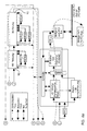
- FIG. 2 shows the functional blocks of a scanner 14 according to the invention, which an automatic document feeder 32, an exposure subsystem 34 optical subsystem 36, a scanner mechanism with platen 38, a Motion control and corresponding sensors 40, scanner interface software 42, Scanner control software 44, logic and control device 46, communication interface hardware 48, CCD and analog front-end electronics 50, a digital one Image processing processor 52, a first buffer 54 for raw image data (so-called. raw image data or RID) and a second buffer 56 for manipulated Image data (so-called manipulated image data or MID).
- the digital image processor 52 and the Buffer 54, 56 form an image processing or [P block 60.
- Die automatic document feeder 32, exposure subsystem 34, the optical subsystem 36, the scanner mechanism with platen 38 and the CCDs and the analog front-end electronics 50 supply digital image data in "raw form", ie. H. raw form, to a buffer 54.
- "raw form" ie. H. raw form
- the original was read in and digitized, but the image data was only slight or not at all edited or manipulated to change the properties of the image.
- only system or hardware errors usually occur Corrected image areas, d. H. z.
- the raw image data stored in the raw image data buffer can be for many different purposes are used, as explained in more detail below.
- the raw image data can e.g. B. directly for viewing or printing on Operator block 30 are directed. This gives the operator the opportunity to review the scanned image and decide whether to continue editing the image is necessary or the data should be changed in the digital image processor. In this It is advantageous if the data in the clipboard is as long as possible to stay saved, the period of the available storage capacity is dependent.
- the raw image data can also be sent to the IP block for manipulation.
- the IP block receives the raw image data (from a camera card interface via the Buffer) for editing and storage in an external memory (or a local memory) located on a PCI bus.
- the one in external storage stored image data can then be forwarded to the host or in digital Image processor can be used for further processing.
- the processing consists of several functions for manipulating the raw image data, e.g. B. pixel correction, Skew correction, screen display, FIR filtering, scaling, Compression, color simulation by random scattering, so-called error diffusion or error diffusion, automatic brightness and color value adjustment etc.
- the manipulated data of the image processor are then in a second Intermediate memory 56 for manipulated image data (MID) is stored.
- MID manipulated image data
- exemplary here two separate image buffers 54, 56 are shown, both buffers 54, 56 can be provided on the same memory chip or on the same card. If the Data from the MID buffer 56 are required, they are stored on the Data interface 48 called.
- FIGS. 3a-d an embodiment of the present invention is shown which is a CCD 70, which passes analog image information to an A / D converter 72.
- For Clarification are process, image and data paths that one of the detail views 3b to 3d lead to another detailed view 3b to 3d marked with letters. The corresponding path continues on the same letter in which it is in the previous figure ends. The same applies to FIGS. 4b to 4e.
- the digital raw image data are transmitted via a clock and a linearity correction block passed to a raw image buffer 54. Then the data extracted and one machining operation or several machining operations in which the data is manipulated before being in a MID Buffer 56 are stored.
- the image editing operations include e.g. B. (but not only) skew corrections, screen display, FIR filtering, Scaling, compression, error diffusion and automatic brightness and color value Adaptation .
- the linearity correction eliminates irregularities in the output of the CCDs constant input balanced.
- pixel correction individual pixel data corrected that deviate from an expected pixel value.
- the skew correction compensates for misalignment of the original documents during scanning occured.
- Screen display, error diffusion and threshold Segmentation method, (so-called thresholding) is the number of data per pixel (from eight Bits per pixel reduced to two bits per pixel).
- FIR filtering is a low-pass filter technique for edge sharpening.
- scaling the image is enlarged or downsized. Compression refers to a typical data compression technique to reduce the amount of memory required to save the image.
- the Error diffusion algorithm is an adaptive method based on the following observation based: The decision was made in a simple binary threshold procedure hit a particular pixel to print, so the error is caused by that decision emerges in the picture, known. If e.g. B. A template is 75% black and a black one Bit is printed, so 25% of a bit is too much black on the print. The error value is distributed to neighboring, randomly selected points. So if too much black was printed, the error is counted towards the surrounding points, so that these contain a little more white. If, on the other hand, too little black was printed, the Error value subtracted from the surrounding points so that these are slightly more black contain. No grid is used for this procedure.
- 4a-e show the sequence of the data flow through the image processor: After the Data formatting 80, gain correction 82, zero offset correction are carried out 84, automatic brightness and color value adjustment 86, Skew correction 88, FIR filtering 90, scaling 92 and a block 94 which Thresholding, screening and error diffusion (as a reproduction method) contains.
- An example of the data manipulation carried out in the IP block is scaling.
- the purpose of scaling is to enlarge a digital image into one Range between 100% and 400% (in 1% steps) or the reduction of the image in a range between 100% and 25% (in 1% increments).
- the scanned images in the scan direction and transverse to the scan direction or enlarged downsized, with the enlargement or reduction in the scan direction and the Enlargement or reduction across the scan direction take place independently of each other, so there is a possibility to enlarge the image in one direction and it zoom out in the other direction at the same time.
- the image reproduction to 100% as well Reductions (in both directions) can be done at full productivity.
- an algorithm decides pixel by pixel whether the pixel in the final image appears (with interpolation) or is omitted. With a 100% Playback is preserved every pixel.
- additional pixels are added used the image to enlarge it.
- the picture to be enlarged is first displayed in the Storage stored, then called up and enlarged.
- the system runs when enlarging at the same clock speed, but has to process a larger amount of data.
- the engine speed of the scanner 14 cannot be changed because the scaling is mathematical, in particular is performed algorithmically by storing the stored raw data in "scaled" Image data (i.e., data stored in the reproducing device / marking device 12 display scaled image to be used).
- An algorithm that can be used for scaling works with a bilinear interpolation method, in which the value of the current pixel and the value of three neighboring pixels are used to determine the pixel value to be stored. Since the position of the desired output pixel can lie between two pixels, a method for interpolating the pixel value from the neighboring pixels is required.
- the bilinear interpolation method has interpolation precision bits and pixel address bits. Two-dimensional scaling can easily be achieved through the use of address registers which define the pixel position of the pixel to be processed for the output scaled image.
- the registers have an integer part and a fractional part, the latter containing a user definable number of precision and interpolation bits.
- Independent X and Y scaling requires the calculation of two delta variables namely one in the scanning direction and one transverse to the scanning direction. For each axis two separate address counters must be provided.
- Bits 9 and 10 determine the interpolation factors involved in the interpolation Pixels can be used. It is both an arithmetic register in the scan direction and a Computing registers are provided transversely to the scanning direction, which work in parallel, so that the final interpolation factor based on the results of both computational registers. Bit 11 can be viewed as an extension or roll-over bit. If this bit is 1 the address counter goes to the next pixel. In Fig. 6 it is shown how a value is determined for a "new pixel". A given pixel A is of a 4x4 matrix of the possible interpolation positions. These 16 positions are calculated using the two bits from the arithmetic register across the scan direction (bits 9 and 10) and the Computing register addressed in scan direction (bits 9 and 10).
- Another scaling method provides that the image lines are stored in a FIFO memory and then called up one after the other in order to decide whether the data should be retained or not.
- a pixel value (800H) for each input pixel is added to the arithmetic register and the result is compared with the magnification value to decide whether there is a rollover case. If the arithmetic register value is equal to or larger than the magnification value, there is a rollover case and the pixel is retained.
- bits 9 and 10 are no longer automatically the interpolation bits. If bits 0 to 11 in the accumulator are zero, the interpolation is "00". If bits 0 to 8 in the accumulator are zero, the following table is used: Bits 10 and 9 Interpolation results 00 00 01 11 10 10 11 01
- the same table can be used for a reduction or enlargement or a combination in order to determine the correct factors for A, B, C, D for determining the new pixel value.
- the calculation is: ((A_Factor x A) + (B_Faktor x B) + (C_Faktor x C) + (D_Faktor x D)) / 16
- Fig. 6 the bilinear interpolation calculation is shown when two interpolation bits be used.
- the integer part of the X and Y address registers has periods and Pixel A towards each other.
- the desired output pixel is in the range of pixels A, B, C and D.
- the fractional part of the X address register contains both Interpolation bits 11.
- the fractional part of the Y address register contains in both Interpolation bits 10.
- the position of the desired output pixel is relative to the four pixels that border it. It should be noted here that it is a 4x4 grid is involved - with three interpolation bits an 8x8 grid would result.
- the Equation to calculate the new pixel has the following coefficients: 2/16 for A, 6/16 for B, 2/16 for C and 6/16 for D. The closer a pixel of the desired the more weighted it is.
- the address registers are used to determine the x and y coordinates of the position of the desired pixels used.
- the following examples illustrate
- a second process is launched Gear set in which the multibit image from the raw image data buffer read out and processed in the image processor 52, e.g. B. on the desired by the operator Dimension is enlarged.
- An advantage of this method is that the FIR filter is not on asymmetrical apertures must be adjusted since the picture in the normal Operating speed was scanned.
- the electronic hardware generates data in the Standard bandwidth, but reads the data at a lower speed than the data coming in from an image. Because the scaling process is in the same mode takes place like the rest of the prepress processes, is a fine adjustment of the Scaling window and the other scaling parameters possible without that Original must be re-scanned.
- the scanner operation according to the invention with the Prepress mode setting in scanner 14 begins.
- This mode allows the image or image data to be viewed at different stages, i.e. H. from the raw image data generated in the scanning device 14 to the “finished” version of the Image after the manipulation of the data in the context of one or more Image editing operations.
- One or more original documents 24 are inserted and scanned.
- the raw image data is stored in the raw image data buffer 54 saved. If necessary, the raw image data is sent to the operator interface 18 or the printer 12 passed. Otherwise it takes place in one Image processing operation or in several image processing operations Data manipulation of the raw image data. After the image processing, the manipulated Image data is stored in a manipulated data buffer 56.
- the manipulated data On request the manipulated data will be sent to the viewer to view or create a printout Operator interface 18 passed.
- the raw image data remain in the raw image data buffer for so long 54 until they are no longer used. That way a scanned image of an original document 24 is repeatedly edited, checked or be scanned until it reaches the desired one, suitable for high-volume printing Has reached state.
- This scanner mode is called "prepress mode", because it allows the image to be processed before the actual printing process.
Abstract
Description
Die vorliegende Erfindung betrifft Scanvorrichtungen gemäß dem Oberbegriff des
Anspruchs 6 und eine Verfahren zur Manipulation von Bildern.The present invention relates to scanning devices according to the preamble of
Die in der vorliegenden Anmeldung verwendeten Bezeichnungen haben dieselbe Bedeutung wie dem Fachmann aus dem Bereich des Digitaldrucks und des Scannens bekannt ist. Der Nutzen der vorliegenden Erfindungen ist jedoch nicht auf diese Bereiche beschränkt, auch wenn der Hauptnutzen der hier beschriebenen Erfindungen besonders in diesen Bereichen deutlich wird.The terms used in the present application have the same Meaning as the specialist in the field of digital printing and scanning is known. However, the utility of the present inventions is not in these areas limited, even if the main benefit of the inventions described here is particularly in in these areas.
Beim Scannen von Dokumenten wird das Original gescannt und als digitales Bild in einem Hauptcomputer, einem sogenannten Host und/oder einer Workstation gespeichert. Wenn das gescannte Bild nicht zum Drucken oder für andere Veröffentlichungsarten geeignet ist, werden die Scanner-Parameter angepasst und das Bild wird neu gescannt und bearbeitet. Wurde das Bild mit höchster Auflösung erfasst, so kann es zur vielfältigen Weiterverarbeitung im Host genutzt werden. Die Durchführung der Änderungen und deren Verarbeitung nimmt aufgrund des hohen dazu benötigten Bildbearbeitungsaufwands in dem Host und/oder der Workstation häufig viel Zeit in Anspruch. Die Bildanpassung zur Kompensation von Scannerparametern ist demgemäß zeit- und arbeitsaufwändig.When scanning documents, the original is scanned and as a digital image in one Main computer, a so-called host and / or a workstation stored. If the scanned image is not suitable for printing or other types of publication, the scanner parameters are adjusted and the image is re-scanned and processed. If the image was captured with the highest resolution, it can be varied Further processing in the host can be used. Implementation of the changes and their Processing takes on due to the high amount of image processing required the host and / or the workstation often takes a long time. The image adjustment for Compensation of scanner parameters is therefore time-consuming and labor-intensive.
Bei Hochleistungs-Scannern tritt dieses Problem in verstärkter Form auf. Bei dieser Art von Scannern werden in einem Stapel angeordnete Vorlagen in Serie einer Bilderfassungsvorrichtung zugeführt. Ist eines der gescannten Bilder aufgrund unzureichender Scannerparameter inakzeptabel, so muss der gesamte Vorlagenstapel neu eingelegt und gescannt werden, damit die inakzeptablen Bilder in der korrekten Reihenfolge bleiben.With high-performance scanners, this problem occurs to an increased extent. With this type from scanners, documents are stacked in a series Image capture device supplied. Is due to one of the scanned images insufficient scanner parameters unacceptable, the entire stack of originals must be new inserted and scanned so that the unacceptable images are correct Order remain.
Ein weiteres Problem von Scannern tritt bei deren Einsatz beim Vergrößern oder Verkleinern von Bildern oder Dokumenten, dem sog. Skalieren auf. Das Vergrößern wird in der Regel durch Reduzieren der Motorgeschwindigkeit des Scanners erreicht, wodurch die Geschwindigkeit reduziert wird, mit welcher der Lesekopf die Vorlage passiert. Dieses Verfahren wird wegen der fest vorgegebenen maximalen Bandbreite der Bildbearbeitungs-Hardware eingesetzt. Die erhöhte Bearbeitungszeit ist direkt proportional zum Skalierungsfaktor. Eine 200%-ige Vergrößerung verursacht z. B. eine 200%-ige Verlängerung der Bearbeitungszeit, da die Motorgeschwindigkeit auf die Hälfte verringert wird. Bei Scannern, die eine 400%-ige Vergrößerung ermöglichen, muss das Motorsteuerungssystem im Bereich von einem Viertel der normalen Geschwindigkeit bis zur normalen Geschwindigkeit korrekt und störungsfrei arbeiten. Anders ausgedrückt: Die maximale Scangeschwindigkeit beträgt das Dreifache der minimalen Scangeschwindigkeit. Dieses Skalierungsverfahren wird auch durch Probleme bei der Filterung mit endlicher Kanalimpulsantwort, der sogenannten Finite Impulse Response (FIR)-Filterung beeinträchtigt. Finite Impulse Response-Filter sind für eine bestimmte Bildblenden konstruiert. Durch Veränderung der Scangeschwindigkeit wird diese Blende in Scanrichtung verändert. Die Filter können zwar zur Anpassung an unterschiedliche Blenden verändert werden, aber die Unterstützung eines nicht-symmetrischen FIR-Filters ist weder eine einfache Aufgabe noch eine kostengünstige Lösung.Another problem with scanners occurs when using them when zooming in or out Shrinking of pictures or documents, the so-called scaling up. The enlargement will usually achieved by reducing the motor speed of the scanner, causing the speed at which the reading head passes the original is reduced. This Process is due to the fixed maximum bandwidth of the image processing hardware used. The increased processing time is directly proportional to the Scaling factor. A 200% increase causes e.g. B. a 200% Extension of the processing time because the motor speed is reduced by half becomes. With scanners that allow a 400% enlargement, this has to be done Motor control system ranging from a quarter of normal speed to work correctly and trouble-free at normal speed. In other words: the maximum scan speed is three times the minimum scan speed. This scaling method is also caused by problems with filtering with finite Channel impulse response, the so-called finite impulse response (FIR) filtering impaired. Finite impulse response filters are for a specific image aperture constructed. By changing the scanning speed, this aperture is in Scanning direction changed. The filters can be used to adapt to different ones Apertures can be changed, but support a non-symmetrical FIR filter is neither an easy task nor an inexpensive solution.
Anstrengungen im Bezug auf derartige Systeme haben zu kontinuierlichen Entwicklungen zur Verbesserung ihrer Vielseitigkeit, ihrer praktischen Einsatzfähigkeit und Effizienz geführt.Efforts related to such systems have continued to evolve to improve their versatility, practicality and efficiency guided.
Aufgabe der vorliegenden Erfindung ist es, eine Scanvorrichtung und eine Verfahren zur Skalierung eines Bildes zu schaffen, das die oben genannten Nachteile nicht aufweist und bei dem die Rohbilddaten in einem Daten-Zwischenspeicher gespeichert werden und der Bediener die Möglichkeit hat, in einem Druckvorstufen-Modus die Rohdaten vor dem Drucken oder der sonstigen Wiedergabe des Bildes zu überprüfen und zu manipulieren.The object of the present invention is to provide a scanning device and a method for To scale an image that does not have the disadvantages mentioned above and in which the raw image data is stored in a data buffer and the Operator has the possibility in a prepress mode the raw data before Check and manipulate printing or other reproduction of the image.
Eine weitere Aufgabe der vorliegenden ist es, eine Scanvorrichtung zu schaffen, der ein Skalieren ohne Veränderung der Geschwindigkeit des Scannermotors ermöglicht. Another object of the present invention is to provide a scanning device using a Scaling without changing the speed of the scanner motor.
Eine erfindungsgemäße Scanvorrichtung, die von einem Bediener bedient wird und in dem gedrucktes Material in elektronische Daten umgewandelt wird, die von einem Anwendergerät verwendet werden, umfasst einen Wandler, welcher Licht in digitale Rohbilddaten umwandelt, einen Bildprozessor, welcher die digitalen Rohbilddaten empfängt und manipuliert sowie manipulierte Bilddaten bereitstellt, einen Ausgabe-Datenpfad, über den die Daten an das Anwendergerät weitergeleitet werden, einen Zwischenspeicher zum Speichern von Daten und eine Kontrollvorrichtung, welche überprüft, ob die digitalen Bilddaten im Zwischenspeicher gespeichert sind, durch den Bildprozessor manipuliert werden, über den Ausgabe-Datenpfad weitergeleitet werden oder durch den Bildprozessor manipuliert und dann im Zwischenspeicher gespeichert werden.A scanning device according to the invention, which is operated by an operator and in which printed material is converted into electronic data by a User equipment used includes a converter that converts light into digital Converts raw image data, an image processor, which the digital raw image data receives and manipulates and provides manipulated image data, an output data path, via which the data is forwarded to the user device, a Buffer for storing data and a control device which checks whether the digital image data is stored in the buffer by which Image processor can be manipulated, forwarded via the output data path or manipulated by the image processor and then stored in the buffer become.
Die vorliegende Erfindung schafft einen nützlichen Druckvorstufen-Modus für einen Scanner, da nicht alle gescannten Bilddaten auf Anhieb für einen Betrachter akzeptabel sind. Deshalb ist es von Vorteil, wenn der Bediener die Möglichkeit hat, sich ein gescanntes Bild anzeigen zu lassen, es zu editieren und wieder anzeigen zu lassen, ohne dass ein zusätzlicher Scanvorgang nötig ist.The present invention provides a useful prepress mode for one Scanner, because not all scanned image data are acceptable to a viewer straight away are. It is therefore an advantage if the operator has the opportunity to register display the scanned image, edit it and display it again without that an additional scan is necessary.
Zur Lösung der genannten Aufgaben sowie ähnlicher Aufgaben umfasst die Erfindung demgemäß die im Folgenden ausführlich beschriebenen und insbesondere in den Ansprüchen aufgeführten Merkmale. Die folgende Beschreibung und die beigefügten Zeichnungen erläutern beispielhafte Ausführungsformen der Erfindung, die jedoch nur einige der Einsatzmöglichkeiten des Grundgedankens der vorliegenden Erfindung aufzeigen. Weitere Aufgaben, Vorteile und neue Merkmale der Erfindung ergeben sich aus der folgenden näheren Beschreibung der Erfindung in Zusammenhang mit den Zeichnungen.The invention comprises the solution to the stated problems and similar problems accordingly those described in detail below and in particular in the Characteristics listed claims. The following description and the attached Drawings illustrate exemplary embodiments of the invention, but only some of the possible uses of the basic idea of the present invention point out. Further objects, advantages and new features of the invention result from the following detailed description of the invention in connection with the Drawings.
Es zeigen:
- Fig. 1
- ein schematisches Blockdiagramm eines erfindungsgemäßen Bildreproduktionssystems;
- Fig. 2
- ein schematisches Diagramm der erfindungsgemäß in einer Scanvorrichtung vorgesehenen Funktionsblöcke;
- Fig. 3a
- ein schematisches Blockdiagramm der Datenleitung durch einen erfindungsgemäßen Scanner
- Fig. 3b-d
- detailliertere Untereinheiten des schematischen Blockdiagramms der Datenleitung durch einen erfindungsgemäßen Scanner;
- Fig. 4a
- ein schematisches Blockdiagramm eines erfindungsgemäßen Bildprozessors;
- Fig. 4b-e
- detailliertere Untereinheiten des schematischen Blockdiagramms eines erfindungsgemäßen Bildprozessors;
- Fig. 5
- eine schematische Darstellung einer Adresse in einem Adresszähler gemäß der vorliegenden Erfindung;
- Fig. 6
- eine Darstellung eines bilinearen Interpolations-Beispiels für ein Pixel gemäß der vorliegenden Erfindung;
- Fig. 7
- ein Flussdiagramm des Betriebs des erfindungsgemäßen Scanners.
- Fig. 1
- a schematic block diagram of an image reproduction system according to the invention;
- Fig. 2
- a schematic diagram of the function blocks provided according to the invention in a scanning device;
- Fig. 3a
- a schematic block diagram of the data line by a scanner according to the invention
- 3b-d
- more detailed subunits of the schematic block diagram of the data line by a scanner according to the invention;
- Fig. 4a
- a schematic block diagram of an image processor according to the invention;
- Fig. 4b-e
- more detailed subunits of the schematic block diagram of an image processor according to the invention;
- Fig. 5
- is a schematic representation of an address in an address counter according to the present invention;
- Fig. 6
- an illustration of a bilinear interpolation example for a pixel according to the present invention;
- Fig. 7
- a flowchart of the operation of the scanner according to the invention.
In den Zeichnungen werden ähnliche oder einander entsprechende Teile in den
unterschiedlichen Ansichten mit ähnlichen Bezugszeichen bezeichnet. In Fig. 1 ist ein
digitales Kopier-/Druckreproduktionssystem 10 gezeigt, das eine (Markier- oder)
Druckvorrichtung 12, eine Originaldokument-Lesevorrichtung, insbesondere eine
Scanvorrichtung 14 und einen Computer bzw. eine Workstation 16 mit einer
Bedienerschnittstelle, z. B. einem Monitor 18 und einer Tastatur 20, umfasst. Die
Markiervorrichtung 12, der Computer/die Workstation 16, der Monitor 18 und die Tastatur
20 bilden gemeinsam oder jeweils ein Anwendergerät 30, der die von der Scanvorrichtung
14 ausgegebenen digitalen Bilddaten über eine Datenausgangsleitung 15 aufnimmt und sie
in irgendeiner Weise reproduziert. Ein Digitaldrucker ist eine Druckvorrichtung 12, die
digitale Bilddaten empfängt und die durch die Daten definierten Bilder auf ein Medium (z.
B. Papier) aufdruckt. Eine typische Einsatzmöglichkeit eines Scanners 14 ist das Lesen von
Originaldokumenten 24, deren digitale Wiedergabe zur Überprüfung durch einen Bediener,
der entscheidet, welche Daten schließlich an eine Druckvorrichtung zur Reproduktion der
Bilder auf Papier weitergegeben werden.In the drawings, similar or corresponding parts in the
different views with similar reference numerals. 1 is a
digital copy /
Die Funktionsweise des Scanners 14 ähnelt insoweit der eines herkömmlichen Kopierers,
als ein Originaldokument 24 zunächst von einer Lampe belichtet wird. Das Licht wird von
den hellen und dunklen Bildbereichen des Originals proportional zur Helligkeit des
Originals reflektiert. Das Licht wird über Spiegel geleitet und mittels einer Linse auf die
Photodetektorelemente gerichtet. Durch die Photodetektorelemente wird das Bild
sequenziell in kleine Punkte (sog. Bildelemente oder Pixel) aufgelöst und das Licht für
jeden Punkt in ein proportionales elektrisches Signal umgewandelt. Es sind verschiedene
Arten von photoelektrischen Wandlern bekannt, z. B. Photodioden, Phototransistoren und
ladungsträgergekoppelten Schaltungen, sog. Charge-Coupled Devices (CCDs) (Auf diese
Weise werden die Tonwerte des Originals in ein Muster aus proportionalen, sequenziellen
Spannungswerten aufgelöst. Das von der CCD gesendete sequenzielle elektrische Signal
entspricht in analoger Form der für jedes Pixel aufgezeichneten Bilddichte. Das elektrische
Signal wird dann von einem A/D-Wandler in ein äquivalentes digitales Signal
umgewandelt. Enthält das Originalbild nur schwarz und weiß, so genügt eine Ausgabe von
nur einem Bit (einer Signallinie) zur Angabe des gesamten Tonwertbereichs. Vorzugsweise
werden jedoch auch Grauwerte wiedergegeben. Mit einer Ausgabe von zwei Bits können
Werte durch vier unterschiedliche Kombinationen aus "1" und "0", nämlich durch "00",
"01", "10" und "11" wiedergegeben werden. Demgemäß verändert sich das (analoge)
Eingabesignal entsprechend, wenn sich die Dichte des Originals von weiß über grau zu
schwarz verändert. Eine Zwei-Bit-Ausgabe ermöglicht eine Einteilung dieses Farbbereichs
in vier Grauwerte zur Umwandlung in ein digitales Signal. Wird eine Vier-Bit-Ausgabe
verwendet, so sind 16 Grauwerte möglich. Hierbei wird deutlich, dass ein digitales Signal
mit einer größeren Zahl von Ausgabe-Bits eine genauere Wiedergabe der unterschiedlichen
Dichten des Originals ermöglicht. Eine Erhöhung der Anzahl von Ausgabe-Bits erfordert
jedoch eine Erhöhung der Speicherkapazität und der Rechenleistung, damit die durch den
Scanvorgang erzeugte größere Datenmenge verarbeitet werden kann. Die vorliegende
Erfindung ermöglicht z. B. eine Ausgabe von acht oder mehr Bits.The operation of the
Nach Umwandlung der einzelnen Spannungswerte in ein elektrisches Signal kann das Bild
mittels eines elektronischer Schaltkreise in einem Bildprozessor durch Signalbearbeitung
verändert werden. Die Scanvorrichtung 14 erzeugt eine Reihe von elektrischen Signalen,
die den Bildgehalt des Originaldokuments 24 wiedergeben. Nach der Bildbearbeitung wird
das elektrische Signal über Übertragungskabel an ein Anwendergerät, z. B. eine
Druckereinheit 12 oder eine andere Bedienerschnittstelle, z. B. einen Computer / eine
Workstation 16, übermittelt, wo das Bild wiedergegeben wird.After converting the individual voltage values into an electrical signal, the picture can
by means of electronic circuits in an image processor by signal processing
to be changed. The
Die Scanvorrichtung 14 umfasst ferner eine automatische Dokumenten-Einzugsvorrichtung
32, die fortlaufend nacheinander Originalvorlagen in Papierform einem
Scannermechanismus mit Auflageplatte 38 zuführt, wo die Vorlagen automatisch durch
den Lesekopf, z. B. eine lineare Anordnung von Festkörper-CCDs eingelesen werden.
Anstelle der Zufuhr von Bogen können auch Dokumente in Buch- oder Bogenform auf den
Scannermechanismus mit Auflageplatte 38 aufgelegt werden.The
In Fig. 2 sind die Funktionsblocks eines erfindungsgemäßen Scanners 14 dargestellt, der
eine automatische Dokumenten-Zuführeinrichtung 32, ein Belichtungs-Untersystem 34, ein
optisches Untersystem 36, einen Scannermechanismus mit Auflageplatte 38, eine
Bewegungssteuerung und entsprechende Sensoren 40, Scanner-Schnittstellensoftware 42,
Scanner-Steuerungssoftware 44, Logik- und Kontrollvorrichtung 46, Kommunikations-Schnittstellenhardware
48, CCD und analoge Frontend-Elektronik 50, einen digitalen
Bildbearbeitungsprozessor 52, einen ersten Zwischenspeicher 54 für Rohbilddaten (sog.
raw image data oder RID) und einen zweiten Zwischenspeicher 56 für manipulierte
Bilddaten (sog. manipulated image data oder MID). Der digitale Bildprozessor 52 und die
Zwischenspeicher 54, 56 bilden einen Bildbearbeitungs- oder [P-Block 60. Die
automatische Dokumenten-Zuführeinrichtung 32, das Belichtungs-Untersystem 34, das
optische Untersystem 36, der Scannermechanismus mit Auflageplatte 38 und die CCDs
sowie die analoge Frontend-Elektronik 50 liefern digitale Bilddaten in "Rohform", d. h.
unbearbeiteter Form, an einen Zwischenspeicher 54. Dies bedeutet, dass das Original
eingelesen und digitalisiert wurde, die Bilddaten aber nur geringfügig oder gar nicht
bearbeitet oder manipuliert wurden, um die Eigenschaften des Bildes zu verändern. Zu
diesem Zeitpunkt werden in der Regel nur system- oder hardwarebedingt fehlerhafte
Bildstellen korrigiert, d. h. es werden z. B. Korrekturen der CCD-Taktgebung sowie
Linearitätskorrekturen und Pixelkorrekturen vorgenommen.2 shows the functional blocks of a
Die im Rohbilddaten-Zwischenspeicher gespeicherten Rohbilddaten können für viele
unterschiedliche Zwecke herangezogen werden, wie im Folgenden näher erläutert wird.
Die Rohbilddaten können z. B. direkt zur Ansicht oder zum Ausdrucken an den
Bedienerblock 30 geleitet werden. Dadurch erhält der Bediener die Möglichkeit, das
gescannte Bild zu überprüfen und zu entscheiden, ob eine weitere Bearbeitung des Bildes
nötig ist oder die Daten im digitalen Bildprozessor geändert werden sollen. In diesem
Zusammenhang ist es von Vorteil, wenn die Daten im Zwischenspeicher so lange wie
möglich gespeichert bleiben, wobei der Zeitraum von der verfügbaren Speicherkapazität
abhängig ist.The raw image data stored in the raw image data buffer can be for many
different purposes are used, as explained in more detail below.
The raw image data can e.g. B. directly for viewing or printing on
Die Rohbilddaten (RID) können auch zur Manipulation an den IP-Block geleitet werden. Der IP-Block erhält die Rohbilddaten (von einer Kamera-Kartenschnittstelle über den Zwischenspeicher) zur Bearbeitung und zur Speicherung in einem externen Speicher (oder einem lokalen Speicher) der sich an einem PCI Bus befindet. Die im externen Speicher gespeicherten Bilddaten können dann an den Host weitergeleitet werden oder im digitalen Bildprozessor zur weiteren Bearbeitung verwendet werden. Die Bearbeitung besteht aus mehreren Funktionen zur Manipulation der Rohbilddaten, z. B. Pixelkorrektur, Schrägstellungskorrektur, Bildschirmdarstellung, FIR Filterung, Skalierung, Komprimierung, Farbsimulation durch zufälliges Streuen, sog. Fehlerdiffusion oder error diffusion, automatische Helligkeits- und Farbwert Anpassung etc. The raw image data (RID) can also be sent to the IP block for manipulation. The IP block receives the raw image data (from a camera card interface via the Buffer) for editing and storage in an external memory (or a local memory) located on a PCI bus. The one in external storage stored image data can then be forwarded to the host or in digital Image processor can be used for further processing. The processing consists of several functions for manipulating the raw image data, e.g. B. pixel correction, Skew correction, screen display, FIR filtering, scaling, Compression, color simulation by random scattering, so-called error diffusion or error diffusion, automatic brightness and color value adjustment etc.
Die manipulierten Daten des Bildprozessors werden anschließend in einem zweiten
Zwischenspeicher 56 für manipulierte Bilddaten (MID) abgelegt. Obwohl hier beispielhaft
zwei separate Bild-Zwischenspeicher 54, 56 gezeigt sind, können beide Zwischenspeicher
54, 56 auf demselben Speicherchip oder auf derselben Karte vorgesehen sein. Wenn die
Daten aus dem MID-Zwischenspeicher 56 benötigt werden, werden sie über die
Datenschnittstelle 48 aufgerufen.The manipulated data of the image processor are then in a
In Fig. 3a-d ist eine Ausführungsform der vorliegenden Erfindung gezeigt, die eine CCD
70 umfasst, die analoge Bildinformationen an einen A/D-Wandler 72 leitet. Zur
Verdeutlichung sind Prozess-, Bild- und Datenpfade, die von einer der Detailansichten 3b
bis 3d zu einer anderen Detailansicht 3b bis 3d führen mit Buchstaben markiert. Der
entsprechende Pfad setzt sich am selben Buchstaben fort, in dem er in der
vorangegangenen Figur endet. Entsprechendes gilt für die Fig. 4b bis 4e.In Figures 3a-d an embodiment of the present invention is shown which is a CCD
70, which passes analog image information to an A /
Die digitalen Rohbilddaten werden über einen Taktgeber und einen Linearitätskorrektur-Block
an einen Rohbild-Zwischenspeicher 54 geleitet. Anschließend werden die Daten
extrahiert und einem Bearbeitungsvorgang oder mehreren Bearbeitungsvorgängen
unterzogen, in denen die Daten manipuliert werden, bevor sie in einem MID
Zwischenspeicher 56 abgelegt werden. Die Bildbearbeitungsvorgänge umfassen z. B. (aber
nicht ausschließlich) Schräglaufkorrekturen, Bildschirmdarstellung, FIR-Filterung,
Skalierung, Komprimierung, Fehlerdiffusion und automatische Helligkeits- und Farbwert
Anpassung .The digital raw image data are transmitted via a clock and a linearity correction block
passed to a
Durch die Linearitätskorrektur werden Unregelmäßigkeiten in den Ausgaben der CCDs bei konstanter Eingabe ausgeglichen. Bei der Pixelkorrektur werden einzelne Pixeldaten korrigiert, die von einem erwarteten Pixelwert abweichen. Die Schrägstellungskorrektur gleicht eine Fehlausrichtung der Originaldokumente aus, die während des Scannens aufgetreten ist. Bei der Bildschirmwiedergabe, der Fehlerdiffusion und dem Schwellenwert Segmentierungsverfahren, (sog. Thresholding) wird die Datenanzahl pro Pixel (von acht Bits pro Pixel auf zwei Bits pro Pixel) reduziert. Die FIR-Filterung ist eine Tiefpass-Filtertechnik zur Kantenschärfung. Beim Skalieren wird das Bild vergrößert oder verkleinert. Komprimierung bezieht sich auf eine typische Datenkomprimierungstechnik zur Reduzierung der zum Speichern des Bildes erforderlichen Speicherkapazität. Der Fehlerdiffusions-Algorithmus ist ein adaptives Verfahren, das auf folgender Beobachtung basiert: Wurde in einem einfachen binären Threshold-Verfahren die Entscheidung getroffen ein bestimmtes Pixel zu drucken, so ist der Fehler, der durch diese Entscheidung im Bild entsteht, bekannt. Wenn z. B. eine Vorlage zu 75% schwarz ist und ein schwarzes Bit gedruckt wird, so ist 25% eines Bits zu viel Schwarz auf dem Druck. Der Fehlerwert wird auf benachbarte, zufällig ausgewählte Punkte verteilt. Wenn also zu viel Schwarz gedruckt wurde, so wird der Fehler auf die umliegenden Punkte angerechnet, so dass diese etwas mehr Weiß enthalten. Wurde dagegen zu wenig Schwarz gedruckt, so wird der Fehlerwert von den umliegenden Punkten abgezogen, so dass diese etwas mehr Schwarz enthalten. Für dieses Verfahren wird kein Raster verwendet. Das entstehende Bild ist stark abhängig von der Wahl der Nachbarpunkte und der Fehlerverteilung. Bei der automatischen Belichtung werden unzureichende Belichtungsniveaus korrigiert. All diese und andere, auch im Rahmen der vorliegenden Erfindung mögliche Bildbearbeitungsfunktionen sind dem Fachmann bekannt, wobei die jeweils angewandte Technik von vielen scannerbedingten Faktoren und Bedienerbedürfnissen abhängig ist.The linearity correction eliminates irregularities in the output of the CCDs constant input balanced. In pixel correction, individual pixel data corrected that deviate from an expected pixel value. The skew correction compensates for misalignment of the original documents during scanning occured. Screen display, error diffusion and threshold Segmentation method, (so-called thresholding) is the number of data per pixel (from eight Bits per pixel reduced to two bits per pixel). FIR filtering is a low-pass filter technique for edge sharpening. When scaling, the image is enlarged or downsized. Compression refers to a typical data compression technique to reduce the amount of memory required to save the image. The Error diffusion algorithm is an adaptive method based on the following observation based: The decision was made in a simple binary threshold procedure hit a particular pixel to print, so the error is caused by that decision emerges in the picture, known. If e.g. B. A template is 75% black and a black one Bit is printed, so 25% of a bit is too much black on the print. The error value is distributed to neighboring, randomly selected points. So if too much black was printed, the error is counted towards the surrounding points, so that these contain a little more white. If, on the other hand, too little black was printed, the Error value subtracted from the surrounding points so that these are slightly more black contain. No grid is used for this procedure. The resulting picture is strong depending on the choice of neighboring points and the error distribution. In the automatic exposure will correct insufficient exposure levels. All these and others, also possible within the scope of the present invention Image editing functions are known to those skilled in the art, with the particular one used Technology depends on many scanner-related factors and operator needs.
In Fig. 4a-e ist der Ablauf des Datenflusses durch den Bildprozessor dargestellt: Nach der
Datenformatierung 80, erfolgen Verstärkungs-Korrektur 82, Nullpunktverschiebungs-Korrektur
84, automatische Helligkeits- und Farbwert Anpassung 86,
Schrägstellungskorrektur 88, FIR-Filterung 90, Skalierung 92 und ein Block 94, der
Thresholding, Rasterung und Fehlerdiffusion (als Wiedergabeverfahren) enthält.4a-e show the sequence of the data flow through the image processor: After the
Ein Beispiel für die im IP-Block vorgenommenen Datenmanipulationen ist die Skalierung.
Der Zweck der Skalierung besteht in der Vergrößerung eines digitalen Bildes in einem
Bereich zwischen 100% und 400% (in 1%-Schritten) oder der Verkleinerung des Bildes in
einem Bereich zwischen 100% und 25% (in 1%-Schritten). Beim Skalieren werden die
gescannten Bilder in die Scanrichtung und quer zur Scanrichtung vergrößert oder
verkleinert, wobei die Vergrößerung oder Verkleinerung in die Scanrichtung und die
Vergrößerung oder Verkleinerung quer zur Scanrichtung unabhängig voneinander erfolgen,
so dass die Möglichkeit besteht, das Bild in die eine Richtung zu vergrößern und es
gleichzeitig in die andere Richtung zu verkleinern. Die Bildwiedergabe zu 100% sowie
Verkleinerungen (in beide Richtungen) können bei voller Produktivität erfolgen. Beim
Verkleinern wird durch einen Algorithmus pixelweise entschieden, ob das Pixel im
endgültigen Bild erscheint (mit Interpolation) oder ausgelassen wird. Bei einer 100%-igen
Wiedergabe bleibt jedes Pixel erhalten. Bei der Vergrößerung werden zusätzliche Pixel in
das Bild eingesetzt, um es zu vergrößern. Das zu vergrößernde Bild wird zunächst im
Speicher abgelegt, dann aufgerufen und vergrößert. Bei der Vergrößerung läuft das System
mit derselben Taktgeschwindigkeit, muss jedoch eine größere Datenmenge verarbeiten.
Durch den Einsatz des Rohdaten-Zwischenspeichers 54 muss die Motorgeschwindigkeit
des Scanners 14 also nicht verändert werden, da das Skalieren mathematisch, insbesondere
algorithmisch durchgeführt wird, indem die gespeicherten Rohdaten in "skalierte"
Bilddaten (d. h. in Daten, die ein in dem Reproduktionsgerät/der Markierungsvorrichtung
12 zu verwendendes skaliertes Bild wiedergeben) umgewandelt werden.An example of the data manipulation carried out in the IP block is scaling.
The purpose of scaling is to enlarge a digital image into one
Range between 100% and 400% (in 1% steps) or the reduction of the image in
a range between 100% and 25% (in 1% increments). When scaling, the
scanned images in the scan direction and transverse to the scan direction or enlarged
downsized, with the enlargement or reduction in the scan direction and the
Enlargement or reduction across the scan direction take place independently of each other,
so there is a possibility to enlarge the image in one direction and it
zoom out in the other direction at the same time. The image reproduction to 100% as well
Reductions (in both directions) can be done at full productivity. At the
Zooming out, an algorithm decides pixel by pixel whether the pixel in the
final image appears (with interpolation) or is omitted. With a 100%
Playback is preserved every pixel. When zooming in, additional pixels are added
used the image to enlarge it. The picture to be enlarged is first displayed in the
Storage stored, then called up and enlarged. The system runs when enlarging
at the same clock speed, but has to process a larger amount of data.
By using the
Ein für die Skalierung verwendbarer Algorithmus arbeitet mit einem bilinearen
Interpolationsverfahren, bei dem der Wert des aktuellen Pixels und der Wert von drei
benachbarten Pixels zur Bestimmung des zu speichernden Pixelswerts herangezogen wird.
Da die Position des gewünschten Ausgabepixels zwischen zwei Pixeln liegen kann, ist ein
Verfahren zur Interpolation des Pixelwerts aus den benachbarten Pixeln erforderlich. Bei
dem bilinearen Interpolationsverfahren gibt es Interpolations-Präzisionsbits und
Pixeladressen-Bits. Zweidimensionale Skalierung kann problemlos durch den Einsatz von
Adressregistern erreicht werden, welche die Pixelposition des zu bearbeitenden Pixels für
das ausgegebene skalierte Bild definieren. Die Register haben einen ganzzahligen Teil und
einen gebrochenen Teil, wobei letzterer eine vom Benutzer definierbare Anzahl von
Präzisions- und Interpolationsbits enthält. Die Anzahl der Präzisionsbits beeinflusst den
Unterschied zwischen dem gewünschten und dem tatsächlichen Skalierungsfaktor: je mehr
Präzisionsbits, desto weniger Fehler. In Fig. 5 ist diese Adresszähler-Komponente in
Interpolationsbits dargestellt. Für jedes Eingabe-Pixel wird dem Adresszähler ein (auf der
Basis des gewählten Skalierungsfaktors) berechneter Delta-Wert hinzugefügt. Dieser Wert
wird wie folgt berechnet:
Werden z. B. 11 Präzisionsbits eingesetzt, so gilt: 211 = 2048. Bei einem Skalierungsfaktor von 150% oder 1,5 ergibt sich: delta = 2048/1,5 = 1365. Der Delta-Wert liegt zwischen 512 und 8192 (für 11 Präzisionsbits und 25% bis 400%).Are z. For example, if 11 precision bits are used, the following applies: 2 11 = 2048. With a scaling factor of 150% or 1.5, the result is: delta = 2048 / 1.5 = 1365. The delta value is between 512 and 8192 (for 11 precision bits and 25% to 400%).
Eine unabhängige X- und Y-Skalierung erfordert die Berechung von zwei Deltavariablen nämlich jeweils eine in Scanrichtung und eine quer zur Scanrichtung. Für jede Achse müssen zwei separate Adresszähler vorgesehen sein.Independent X and Y scaling requires the calculation of two delta variables namely one in the scanning direction and one transverse to the scanning direction. For each axis two separate address counters must be provided.
Beim Vergrößern wird der Adressenwert für jedes Ausgabepixel durch Addition des
Vergrößerungswerts zum vorhergehenden Wert im Adresszählerrechenregister berechnet.
Die Bits 9 und 10 bestimmen die Interpolationsfaktoren, die bei der Interpolation zwischen
Pixeln verwendet werden. Es ist sowohl ein Rechenregister in Scanrichtung und ein
Rechenregister quer zur Scanrichtung vorgesehen, die parallel arbeiten, so dass der
endgültige Interpolationsfaktor auf den Ergebnissen beider Rechenregister basiert. Bit 11
kann als Verlängerungs- oder Roll-over-Bit betrachtet werden. Wenn dieses Bit den Wert 1
hat, so geht der Adresszähler zum nächsten Pixel über. In Fig. 6 ist gezeigt, wie ein Wert
für ein "neues Pixel" bestimmt wird. Ein vorgegebenes Pixel A ist von einer 4x4-Matrix
der möglichen Interpolationspositionen umgeben. Diese 16 Positionen werden mittels der
zwei Bits aus dem Rechenregister quer zur Scanrichtung (Bits 9 und 10) und des
Rechenregister in Scanrichtung (Bits 9 und 10) adressiert.When zooming in, the address value for each output pixel is added by adding the
Increase value to the previous value calculated in the address counter calculation register.
Ein weiteres erfindungsgemäßes Skalierungsverfahren sieht vor, dass die Bildlinien in
einem FIFO-Speicher gespeichert werden und dann eine nach der anderen aufgerufen
werden, um zu entscheiden, ob die Daten erhalten bleiben sollen oder nicht. Anstelle der
Addition des Vergrößerungswerts zum Rechenregister wird ein Pixelwert (800H) für jedes
eingegebene Pixel zum Rechenregister addiert und das Ergebnis mit dem
Vergrößerungswert verglichen, um zu entscheiden, ob ein Roll-over-Fall vorliegt. Ist der
Rechenregister-Wert gleich dem Vergrößerungswert oder größer als der
Vergrößerungswert, so liegt ein Roll-over-Fall vor und das Pixel bleibt erhalten. Bei
diesem Verfahren sind die Bits 9 und 10 nicht mehr automatisch die Interpolationsbits.
Sind die Bits 0 bis 11 im Akkumulator gleich Null, so ist die Interpolation gleich "00".
Wenn die Bits 0 bis 8 im Akkumulator gleich Null sind, kommt die folgende Tabelle zum
Einsatz:
Ansonsten gilt: Interpolation = Inverses der Bits 9 und 10.Otherwise: Interpolation = inverse of
Mit der Translation der Interpolationsbits sowohl in Scanrichtung als auch quer zur
Scanrichtung kann bei einer Verkleinerung oder einer Vergrößerung oder einer
Kombination dieselbe Tabelle eingesetzt werden, um zur Bestimmung des neuen
Pixelwerts die korrekten Faktoren zu A, B, C, D zu ermitteln. Die Berechnung lautet:
In Fig. 6 ist die bilineare Interpolationsberechnung gezeigt, wenn zwei Interpolationsbits
verwendet werden. Der ganzzahlige Teil der X- und Y-Adressregister weist Punkt und
Pixel A einander zu. Das gewünschte Ausgabepixel liegt im Bereich der Pixel A, B, C und
D. In Fig. 6 enthält der gebrochene Teil des X-Adressenregisters in beiden
Interpolationsbits 11. Der gebrochene Teil des Y-Adressregisters enthält in beiden
Interpolationsbits 10. In Fig. 6 ist die Position des gewünschten Ausgabepixels relativ zu
den vier Pixel gezeigt, die es begrenzen. Zu beachten ist hierbei, dass es sich um ein 4x4-Gitternetz
handelt - bei drei Interpolationsbits würde sich ein 8x8-Gitternetz ergeben. Die
Gleichung zur Berechnung des neuen Pixels hat die folgenden Koeffizienten: 2/16 für A,
6/16 für B, 2/16 für C und 6/16 für D. Je näher ein Pixel der gewü
liegt, desto stärker wird es gewichtet.In Fig. 6 the bilinear interpolation calculation is shown when two interpolation bits
be used. The integer part of the X and Y address registers has periods and
Pixel A towards each other. The desired output pixel is in the range of pixels A, B, C and
D. In Fig. 6, the fractional part of the X address register contains both
Interpolation bits 11. The fractional part of the Y address register contains in both
Die Adressenregister werden zur Bestimmung der x- und y-Koordinaten der Position des gewünschten Pixels eingesetzt. Die folgenden Beispiele verdeutlicThe address registers are used to determine the x and y coordinates of the position of the desired pixels used. The following examples illustrate
Für jede Adresse wird die Adresse um 2048/0,50 = 4096 erhöht.

Für jede Adresse wird die Adresse um 2048/0,75 = 2731 erhöht.

Für jede Adresse wird die Adresse um 2048/2,0 = 1024 erhöht.

Bei der vorliegenden Skalierungstechnik wird ein Multibit-Bild mit normaler
Geschwindigkeit erfasst und in einem Multibit-Rohbilddaten-Zwischenspeicher 54
gespeichert. Kurz nach Beginn des Bilderfassungsprozesses wird ein zweiter Prozess in
Gang gesetzt, in dem das Multibit-Bild aus dem Rohbilddaten-Zwischenspeicher
ausgelesen und im Bildprozessor 52 bearbeitet, z. B. auf das vom Bediener gewünschte
Maß vergrößert wird. Ein Vorteil dieses Verfahrens liegt darin, dass der FIR-Filter nicht an
asymmetrische Blenden angepasst werden muss, da das Bild in der normalen
Betriebsgeschwindigkeit gescannt wurde. Die elektronische Hardware erzeugt Daten in der
Standard-Bandbreite, liest jedoch die Daten mit einer geringeren Geschwindigkeit ein als
die von einem Bild eingehenden Daten. Da der Skalierungsprozess im selben Modus
stattfindet wie der Rest der Druckvorstufen-Prozesse, ist eine Feineinstellung des
Skalierungsfensters und der sonstigen Skalierungsparameter möglich, ohne dass das
Original neu eingescannt werden muss.In the present scaling technique, a multibit picture with normal
Speed recorded and in a multibit raw
Anhand von Fig. 7 wird deutlich, dass der Scannerbetrieb erfindungsgemäß mit der
Einstellung des Druckvorstufen-Modus im der Scanvorrichtung 14 beginnt. Dieser Modus
ermöglicht die Ansicht des Bildes oder der Bilddaten in unterschiedlichen Stadien, d. h.
von den in der Scanvorrichtung 14 erzeugten Rohbilddaten bis zur "fertigen" Version des
Bildes nach der Manipulation der Daten im Rahmen einer oder mehrerer
Bildbearbeitungsvorgänge. Ein Originaldokument oder mehrere Originaldokumente 24
werden eingelegt und gescannt. Die Rohbilddaten werden im Rohbilddaten-Zwischenspeicher
54 gespeichert. Bei Bedarf werden die Rohbilddaten an die Bediener-Schnittstelle
18 oder den Drucker 12 geleitet. Andernfalls erfolgt in einem
Bildbearbeitungsvorgang oder in mehreren Bildbearbeitungsvorgängen eine
Datenmanipulation der Rohbilddaten. Nach der Bildbearbeitung werden die manipulierten
Bilddaten in einem Zwischenspeicher für manipulierte Daten 56 gespeichert. Auf Abfrage
werden die manipulierten Daten zur Ansicht oder zur Erstellung eines Ausdrucks an die
Bediener-Schnittstelle 18 geleitet. Die Rohbilddaten verbleiben so lange im Rohbilddaten-Zwischenspeicher
54, bis keine Verwendung mehr für sie besteht. Auf diese Weise kann
ein gescanntes Bild einer Originalvorlage 24 so lange immer wieder editiert, überprüft oder
gescannt werden, bis es den gewünschten, zum Drucken mit hoher Auflage geeigneten
Zustand erreicht hat. Dieser Scannermodus wird als "Druckvorstufen-Modus" bezeichnet,
da er eine Bearbeitung des Bildes vor dem eigentlichen Druckvorgang ermöglicht.It is clear from FIG. 7 that the scanner operation according to the invention with the
Prepress mode setting in
Hierbei wird deutlich, dass die vorliegende Erfindung eine neues Merkmal für einen hochauflösenden Hochleistungsscanner vorschlägt. Obwohl die Erfindung anhand beispielhafter Ausführungsformen gezeigt und beschrieben wurde, sollte für den Fachmann klar sein, dass Änderungen, Auslassungen und Zusätze möglich sind, ohne von dem Grundgedanken und dem Gültigkeitsbereich der Erfindung abzuweichen. It is clear here that the present invention is a new feature for a proposes high-resolution high-performance scanner. Although the invention is based on exemplary embodiments have been shown and described, should be understood by those skilled in the art be clear that changes, omissions and additions are possible without this To deviate basic ideas and the scope of the invention.
- 1010th
- Kopier-/DruckreproduktionssystemCopy / print reproduction system
- 1212th
- Markier-/DruckvorrichtungMarking / printing device
- 1414
- ScanvorrichtungScanning device
- 1515
- DatenausgangsleitungData output line
- 1616
- Computer / WorkstationComputer / workstation
- 1818th
- Monitormonitor
- 2020th
- Tastaturkeyboard
- 2424th
- OriginaldokumentOriginal document
- 3030th
- AnwendergerätUser device
- 3232
- automatische Dokumenten-Einzugsvorrichtungautomatic document feeder
- 3434
- Belichtungs-UntersystemExposure subsystem
- 3636
- optisches Untersystemoptical subsystem
- 3838
- Scannermechanismus mit AuflageplatteScanner mechanism with platen
- 4040
- SensorenSensors
- 4242
- Scanner-SchnittstellensoftwareScanner interface software
- 4444
- Scanner-SteuerungssoftwareScanner control software
- 4646
- KontrollvorrichtungControl device
- 4848
- Kommunikations-SchnittstellenhardwareCommunication interface hardware
- 5050
- CCD und analoge Frontend-ElektronikCCD and analog front-end electronics
- 5252
- digitaler Bildprozessordigital image processor
- 5454
- Rohbilddaten-ZwischenspeicherRaw image data buffer
- 5656
- Zwischenspeicher für manipulierte DatenCache for manipulated data
- 6060
- BildbearbeitungsblockImaging block
- 7272
- A/D-WandlerA / D converter
- 8080
- DatenformatierungData formatting
- 8282
- Tonwertzunahme-KorrekturDot gain correction
- 8484
- Nullpunktverschiebungs-KorrekturZero offset correction
- 8686
- automatische Helligkeits- und Farbwert Anpassungautomatic brightness and color value adjustment
- 8888
- SchrägstellungskorrekturSkew correction
- 9090
- FIR-FilterungFIR filtering
- 9292
- SkalierungScaling
- 9494
- Block für WiedergabeverfahrenPlayback block
Claims (16)
dadurch gekennzeichnet, dass das Bild in digitale Bilddaten konvertiert (34, 36, 50) wird, die in einem Zwischenspeicher (54, 56) gespeichert werden und wahlweise zur Manipulation der digitalen Bilddaten an einen Bildprozessor (52) oder an die Anwendervorrichtung (12, 14, 16, 18) geleitet werden.Method for reproducing the image of a printed original document (24) in the form of electronic data for use by a user device (12, 14, 16, 18),
characterized in that the image is converted (34, 36, 50) into digital image data, which are stored in a buffer (54, 56) and optionally for manipulating the digital image data to an image processor (52) or to the user device (12, 14, 16, 18).
dadurch gekennzeichnet, dass es sich bei dem Anwendergerät um eine Scanvorrichtung (14) handelt.Method according to claim 1,
characterized in that the user device is a scanning device (14).
dadurch gekennzeichnet, dass die Wiedergabe des Bildes mittels einer digitalen Markier-/Druckvorrichtung (12) und/oder Computer/Werkstation (16) durchgeführt wird.Method according to one of claims 1 to 2,
characterized in that the reproduction of the image is carried out by means of a digital marking / printing device (12) and / or computer / work station (16).
dadurch gekennzeichnet, dass die Manipulation des Bildes ein Skalieren des Bildes (40) umfasst.Method according to one of claims 1 to 3,
characterized in that the manipulation of the image comprises scaling the image (40).
dadurch gekennzeichnet, dass bei der Manipulation der digitalen Bilddaten eine bilineare Interpolation erfolgt. Method according to one of claims 1 to 4,
characterized in that a bilinear interpolation takes place in the manipulation of the digital image data.
gekennzeichnet durch,
einen Bildprozessor (52), der die digitalen Bilddaten empfängt und manipuliert und manipulierte Bilddaten erzeugt und einen Zwischenspeicher (54, 56) zum Speichern der Daten.Scanning device (14) for converting original documents (24) into electronic data, which are used by a user device (12, 16, 18), with a converter (34, 36, 50) for converting the image into digital image data and with a Output data path (15) for forwarding the manipulated digital image data to the user device (12, 16, 18),
characterized by
an image processor (52) which receives and manipulates the digital image data and generates manipulated image data and an intermediate memory (54, 56) for storing the data.
dadurch gekennzeichnet, dass es eine Kontrollvorrichtung (46) beeinhaltet, welche die digitalen Bilddaten an den Bildprozessor (52), den Ausgabedatenpfad (15) und den Zwischenspeicher (54, 56) leitet.Scanning device according to claim 6,
characterized in that it includes a control device (46) which forwards the digital image data to the image processor (52), the output data path (15) and the buffer (54, 56).
gekennzeichnet durch
eine Kontrollvorrichtung (46), die überprüft, ob die digitalen Bilddaten
marked by
a control device (46) which checks whether the digital image data
gekennzeichnet durch
eine Kontrollvorrichtung (46), die die Verwendung der digitalen Bilddaten in mindestens zwei Betriebsarten zulässt:
marked by
a control device (46) which permits the use of the digital image data in at least two operating modes:
gekennzeichnet durch
eine Kontrollvorrichtung (46) zur Verwendung der digitalen Bilddaten in mindestens drei Betriebsarten:
marked by
a control device (46) for using the digital image data in at least three operating modes:
gekennzeichnet durch
marked by
dadurch gekennzeichnet, dass die Scanvorrichtung Einzugsmittel (32) zur Zufuhr der Originaldokumente umfasst.Scanning device according to one of claims 6 to 12,
characterized in that the scanning device comprises feed means (32) for feeding the original documents.
dadurch gekennzeichnet, dass das Anwendergerät eine digitale Markier-/Druckvorrichtung (12) und/oder ein Workstation /Computer (16) ist.Scanning device according to one of claims 6 to 13,
characterized in that the user device is a digital marking / printing device (12) and / or a workstation / computer (16).
dadurch gekennzeichnet, dass die Manipulation des Bildes ein Skalieren des Bildes (40) einschließt. Scanning device according to one of claims 6 to 14,
characterized in that the manipulation of the image includes scaling the image (40).
dadurch gekennzeichnet, dass bei der Manipulation der digitalen Bilddaten eine bilineare Interpolation erfolgt.Scanning device according to one of claims 6 to 15,
characterized in that a bilinear interpolation takes place in the manipulation of the digital image data.
Applications Claiming Priority (2)
| Application Number | Priority Date | Filing Date | Title |
|---|---|---|---|
| US20494300P | 2000-05-17 | 2000-05-17 | |
| US204943P | 2000-05-17 |
Publications (1)
| Publication Number | Publication Date |
|---|---|
| EP1158769A1 true EP1158769A1 (en) | 2001-11-28 |
Family
ID=22760114
Family Applications (1)
| Application Number | Title | Priority Date | Filing Date |
|---|---|---|---|
| EP01110175A Withdrawn EP1158769A1 (en) | 2000-05-17 | 2001-05-07 | Scanner with prepress mode |
Country Status (2)
| Country | Link |
|---|---|
| EP (1) | EP1158769A1 (en) |
| DE (1) | DE10122102A1 (en) |
Citations (6)
| Publication number | Priority date | Publication date | Assignee | Title |
|---|---|---|---|---|
| EP0009378A1 (en) * | 1978-09-14 | 1980-04-02 | Xerox Corporation | Image transcribing apparatus |
| GB2117902A (en) * | 1982-04-06 | 1983-10-19 | Loge Interpretation Syst | Colour detection and-or modification |
| US4468755A (en) * | 1980-10-31 | 1984-08-28 | Tokyo Shibaura Denki Kabushiki Kaisha | Document size conversion circuit for a document filing system |
| US4533942A (en) * | 1982-05-28 | 1985-08-06 | Dr. -Ing. Rudolf Hell Gmbh | Method and apparatus for reproducing an image which has a coarser resolution than utilized in scanning of the image |
| EP0246010A1 (en) * | 1986-05-12 | 1987-11-19 | Crosfield Electronics Limited | Image display |
| US4833625A (en) * | 1986-07-09 | 1989-05-23 | University Of Arizona | Image viewing station for picture archiving and communications systems (PACS) |
-
2001
- 2001-05-07 EP EP01110175A patent/EP1158769A1/en not_active Withdrawn
- 2001-05-07 DE DE2001122102 patent/DE10122102A1/en not_active Withdrawn
Patent Citations (6)
| Publication number | Priority date | Publication date | Assignee | Title |
|---|---|---|---|---|
| EP0009378A1 (en) * | 1978-09-14 | 1980-04-02 | Xerox Corporation | Image transcribing apparatus |
| US4468755A (en) * | 1980-10-31 | 1984-08-28 | Tokyo Shibaura Denki Kabushiki Kaisha | Document size conversion circuit for a document filing system |
| GB2117902A (en) * | 1982-04-06 | 1983-10-19 | Loge Interpretation Syst | Colour detection and-or modification |
| US4533942A (en) * | 1982-05-28 | 1985-08-06 | Dr. -Ing. Rudolf Hell Gmbh | Method and apparatus for reproducing an image which has a coarser resolution than utilized in scanning of the image |
| EP0246010A1 (en) * | 1986-05-12 | 1987-11-19 | Crosfield Electronics Limited | Image display |
| US4833625A (en) * | 1986-07-09 | 1989-05-23 | University Of Arizona | Image viewing station for picture archiving and communications systems (PACS) |
Also Published As
| Publication number | Publication date |
|---|---|
| DE10122102A1 (en) | 2001-11-22 |
Similar Documents
| Publication | Publication Date | Title |
|---|---|---|
| DE3645046C2 (en) | ||
| DE3224319C2 (en) | Method and device for determining the type of density level distribution of an image area | |
| US6469801B1 (en) | Scanner with prepress scaling mode | |
| DE19816123B4 (en) | A method of generating multiple renditions of an image with a multiple image scanner | |
| DE3339002C2 (en) | Method and device for processing an image signal | |
| DE2948341A1 (en) | METHOD FOR PROCESSING IMAGE ELEMENTS AND DEVICE FOR PROCESSING AN IMAGE DATA SERIES | |
| DE60111816T2 (en) | Adaptive filtering method and apparatus for descreening sampled halftone image data | |
| DE3522707A1 (en) | IMAGE PROCESSING DEVICE | |
| DE3640369C2 (en) | ||
| DE2654481A1 (en) | FAKSIMILE REMOTE IMAGE TRANSFER DEVICE | |
| DE3520405C2 (en) | ||
| DE69631812T2 (en) | System and method for a highly addressable printing system | |
| DE3037127A1 (en) | IMAGE GENERATION METHOD AND DEVICE | |
| DE3436631C2 (en) | ||
| EP0095514A1 (en) | Method and apparatus for the reproduction of an image with a coarser resolution than during picture scanning | |
| EP0132453A1 (en) | Method and apparatus for minimizing errors during the digital processing of electric signals | |
| DE69937985T2 (en) | Image processing apparatus and method | |
| DE3527301A1 (en) | Image reading device | |
| DE3521682A1 (en) | METHOD FOR SCANING AND RECORDING IMAGES | |
| DE19538030A1 (en) | Access table with higher accuracy from a access table with lower accuracy for improved sound adjustment | |
| DE4409389A1 (en) | Image processing device | |
| DE4028973A1 (en) | IMAGE READING DEVICE FOR AN IMAGE RECORDING DEVICE | |
| DE3505796A1 (en) | METHOD FOR COMPRESSING IMAGE SIGNALS | |
| EP1158769A1 (en) | Scanner with prepress mode | |
| DE102006053351A1 (en) | Methods and apparatus for merging and outputting images |
Legal Events
| Date | Code | Title | Description |
|---|---|---|---|
| PUAI | Public reference made under article 153(3) epc to a published international application that has entered the european phase |
Free format text: ORIGINAL CODE: 0009012 |
|
| 17P | Request for examination filed |
Effective date: 20010827 |
|
| AK | Designated contracting states |
Kind code of ref document: A1 Designated state(s): AT BE CH CY DE DK ES FI FR GB GR IE IT LI LU MC NL PT SE TR |
|
| AX | Request for extension of the european patent |
Free format text: AL;LT;LV;MK;RO;SI |
|
| AKX | Designation fees paid |
Free format text: AT BE CH CY DE DK ES FI FR GB GR IE IT LI LU MC NL PT SE TR |
|
| RAP1 | Party data changed (applicant data changed or rights of an application transferred) |
Owner name: EASTMAN KODAK COMPANY |
|
| STAA | Information on the status of an ep patent application or granted ep patent |
Free format text: STATUS: THE APPLICATION HAS BEEN WITHDRAWN |
|
| 18W | Application withdrawn |
Effective date: 20060316 |