EP1158456B1 - Barcode system - Google Patents
Barcode system Download PDFInfo
- Publication number
- EP1158456B1 EP1158456B1 EP01304584A EP01304584A EP1158456B1 EP 1158456 B1 EP1158456 B1 EP 1158456B1 EP 01304584 A EP01304584 A EP 01304584A EP 01304584 A EP01304584 A EP 01304584A EP 1158456 B1 EP1158456 B1 EP 1158456B1
- Authority
- EP
- European Patent Office
- Prior art keywords
- barcode
- image
- message
- visually significant
- matrices
- Prior art date
- Legal status (The legal status is an assumption and is not a legal conclusion. Google has not performed a legal analysis and makes no representation as to the accuracy of the status listed.)
- Expired - Lifetime
Links
Images


Classifications
-
- G—PHYSICS
- G06—COMPUTING; CALCULATING OR COUNTING
- G06K—GRAPHICAL DATA READING; PRESENTATION OF DATA; RECORD CARRIERS; HANDLING RECORD CARRIERS
- G06K19/00—Record carriers for use with machines and with at least a part designed to carry digital markings
- G06K19/06—Record carriers for use with machines and with at least a part designed to carry digital markings characterised by the kind of the digital marking, e.g. shape, nature, code
- G06K19/06009—Record carriers for use with machines and with at least a part designed to carry digital markings characterised by the kind of the digital marking, e.g. shape, nature, code with optically detectable marking
- G06K19/06037—Record carriers for use with machines and with at least a part designed to carry digital markings characterised by the kind of the digital marking, e.g. shape, nature, code with optically detectable marking multi-dimensional coding
-
- G—PHYSICS
- G06—COMPUTING; CALCULATING OR COUNTING
- G06K—GRAPHICAL DATA READING; PRESENTATION OF DATA; RECORD CARRIERS; HANDLING RECORD CARRIERS
- G06K1/00—Methods or arrangements for marking the record carrier in digital fashion
- G06K1/12—Methods or arrangements for marking the record carrier in digital fashion otherwise than by punching
- G06K1/121—Methods or arrangements for marking the record carrier in digital fashion otherwise than by punching by printing code marks
-
- G—PHYSICS
- G06—COMPUTING; CALCULATING OR COUNTING
- G06K—GRAPHICAL DATA READING; PRESENTATION OF DATA; RECORD CARRIERS; HANDLING RECORD CARRIERS
- G06K19/00—Record carriers for use with machines and with at least a part designed to carry digital markings
- G06K19/06—Record carriers for use with machines and with at least a part designed to carry digital markings characterised by the kind of the digital marking, e.g. shape, nature, code
- G06K19/06009—Record carriers for use with machines and with at least a part designed to carry digital markings characterised by the kind of the digital marking, e.g. shape, nature, code with optically detectable marking
- G06K19/06018—Record carriers for use with machines and with at least a part designed to carry digital markings characterised by the kind of the digital marking, e.g. shape, nature, code with optically detectable marking one-dimensional coding
- G06K19/06028—Record carriers for use with machines and with at least a part designed to carry digital markings characterised by the kind of the digital marking, e.g. shape, nature, code with optically detectable marking one-dimensional coding using bar codes
Definitions
- the present invention relates generally to bar codes and more specifically to a method and apparatus for generating and decoding a visually significant barcode.
- Barcodes are information carrying graphical patterns designed for easy and reliable automatic retrieval.
- the most common barcodes are known as one-dimensional barcodes . These graphical patterns vary in a single dimension (e.g. the horizontal dimension), and are constant in the other dimension (e.g., the vertical dimension).
- One-dimensional barcodes are employed in low information content applications like product index registry (e.g. automatic price tagging and inventory management), or serial number registry (e.g. test-tube tagging in automated medical tests).
- product index registry e.g. automatic price tagging and inventory management
- serial number registry e.g. test-tube tagging in automated medical tests.
- Common examples of one-dimensional barcodes are those barcodes that are affixed or printed on the packages of items purchased at a supermarket or department store. These barcodes typically can only encode limited information, such as the price of the item and the manufacturer. The items having the barcodes are scanned at a checkout counter to facilitate the tallying up of a total receipt.
- Two-dimensional barcodes In order to convey more information on the same surface area, two-dimensional barcodes were developed. Two-dimensional barcodes involve intricate patterns that vary in both the horizontal and the vertical dimensions. Two-dimensional barcodes are used in applications that require more information contents. For example, two-dimensional barcodes can be used to encode mail addresses for automated mail reading and distribution systems. Mail carrier companies can use the two-dimensional bar code on shipping packages to encode shipper information, recipient information, tracking information, etc. In another example, two-dimensional barcodes can be used to encode the compressed content of a printed page to avoid the need for optical character recognition at the receiving end.
- U.S. Pat. Nos. 5,060,980, 5,486,686, and 5,459,307 illustrate an exemplary 2D barcode system.
- This system utilizes short black bars that have a forward orientation or a backward orientation (e.g., bars that are orientated at either 45% or 135% with respect to a reference) to render the barcode.
- the two possible orientations of the bar allow information (e.g., 1 or 0) to be encoded therein.
- This system offers a limited improvement over the traditional 2D barcode in that the appearance of these short black bars while still distracting to the human visual system is less so than the traditional 2D barcode. Consequently, it is asserted by these patents that a barcode utilizing these bars can be placed in the background of a document without excessively distracting a person reading such a document.
- WO-A-00/11599 discloses a method for decoding a message embedded in a pattern of pixels.
- the method includes the steps of determining the pixel values for pixels from the pattern of pixels, determining binary values from the pixel values for pixels from the pattern of pixels; and determining the embedded message from the binary values.
- the pixels have a range of pixel values between a maximum and a minimum.
- the pixels are divided into cells each having glyph cell and background pixels.
- the binary value of a glyph pixel is determined by the contrast the glyph pixel has with its background pixels.
- the method can be used to decode embedded web-site address from an image with a foreground image and the embedded web-site address.
- the present invention seeks to provide an improved barcode system.
- the preferred embodiment can provide a barcode which can be reliably generated and scanned regardless of the type of machine and the manufacturer of the machine.
- the barcode can be robust to photocopying (i.e., the barcode can be scanned and information embedded therein decoded from a copy of the originally rendered barcode) and common office document degradation.
- the preferred embodiments can also provide a visually significant 2D bar code that is robust to distortions in the paper path and that overcomes the disadvantages set forth previously.
- the preferred barcode pattern with visual significance can be printed and read by standard office equipment.
- the preferred system includes an encoding module for receiving a message and a logo and generating a visually significant barcode based on these inputs.
- a decoding module is also provided for receiving an acquired version of a visually significant barcode that may have been degraded in a typical document handling channel (e.g., through the printing, scanning, or copying process) and for recovering the message specified by the visually significant barcode.
- FIG. 1 is a block diagram illustrating an office environment in which one embodiment of the visually significant bar code system (VSBCS) 10 that does not accept user input can be implemented.
- the visually significant bar code system (VSBCS) 10 includes an encoding module 14 for generating a visually significant bar code (VSBC) 20 by utilizing a rendering technique and a decoding module 24 for decoding an acquired version 48 of a hard copy (e.g., a first hard copy 38, a copy 54 of the first hard copy 38, or a second hard copy 56) that includes a visually significant bar code (VSBC) and for recovering a message 60 that is specified in the acquired version 48.
- the VSBC 20 can be rendered by utilizing rendering techniques that are well-known to those of ordinary skill in the art.
- the VSBC 20 is rendered by utilizing a halftone algorithm to generate a halftoned VSBC 20.
- the system 10 can communicate with a driving program 15 for providing the logo 16 and the message 18 and also communicate with a driven program 70 for utilizing the recovered message 48 for a particular application.
- the encoding module 14 includes a first input for receiving a logo 16, a second input for receiving a message 18, and an output for generating the visually significant bar code (VSBC) 20.
- the message 18 can be any information that a system designer specifies.
- logo 16 can be any graphical pattern that has visual significance, which is in sharp contrast to prior 2D bar codes that do not make sense as graphical entities.
- logo 16 can include, but is not limited to, an actual logo, graphics, a picture, text, a text box, an image, or any other pattern that has visual significance.
- Exemplary logos can include a company logo, an application logo, or action logo.
- Exemplary graphics can be frames, button marks, or background.
- An example of text is a text box having the words "This box contains important data!"
- the VSBC can be a bar code pattern that is embedded in the graphical design of text, pictures, images, borders, or the background of a document.
- the VSBC pattern may be, but is not limited to, a binary image (e.g., a black and white dot pattern), a multi-level image (e.g., a gray-level image), or a multilevel color image that is generated by encoding module 14.
- the encoding module 14 is described in greater detail hereinafter with reference to FIG. 5.
- the office environment typically includes office equipment, such as a personal computer (PC) (not shown), a printer 30 having a print engine 34, a scanner 40 having a scan engine 44, a facsimile machine (not shown), and a copier 50 for making copies of documents (e.g., copy 54).
- the print engine 34 receives images (e.g., halftoned images) from sources, such as the encode module 14, and renders these images to create hard copies, such as hard copy 38 with a first VSBC (L1).
- the scan engine 44 receives a hard copy (e.g., a hard copy 38 or 54 with a first VSBC (L1) or a second hard copy 56 with a second VSBC (L2)), generates an acquired version 48 (e.g.
- the scanner 40 can be replaced with a digital camera for acquiring a version of the visually significant barcode.
- the scan engine 44 can be any acquisition engine for capturing the VSBC and providing an acquired version (e.g., a digital representation) of the VSBC.
- the VSBC along with the remainder of the document is provided to a printer, such as printer 30.
- the printer 30 then utilizes the print engine 34 to render a first hard copy 38 that includes a first VSBC (L1).
- the hard copy 38 may then be provided directly to a scanner, such as scanner 44, to generate a scanned version 48.
- the hard copy 38 can first be copied once or several times utilizing a copier, such as the copier 50. Thereafter, the copied version (e.g., copy 54) can be provided to the scanner 44 to generate the scanned version 48.
- a second hard copy (e.g., hard copy 56) can be generated (e.g., printed or copied) by utilizing a printer (not shown) different from printer 30 that is part of a separate office.
- the logo 16 can vary from application to application (e.g., first VSBC (L1) or second VSBC (L2)) and can be specified by a system designer
- the decoding module 24 receives the acquired version 48 and recovers the message 60 encoded in the acquired version 48. For example, if the acquired version corresponds to the first hard copy 38 or to the copy 54, then the message in the first VSBC (L1) is recovered as the message 60. Alternatively, if the acquired version corresponds to the second hard copy 56 or photocopies thereof, then the message in the second VSBC (L2) is recovered as the message 60.
- the message 60 is then provided to a driven application 70 that performs one or more pre-determined functions or tasks, examples of which are described in greater detail hereinafter with reference to FIG. 3.
- FIG. 2 is a block diagram illustrating an office environment in which an alternative embodiment of the visually significant bar code system 10A that accepts user input can be implemented.
- This visually significant bar code system 10B is similar to the system 10A illustrated in FIG. 1, except that this system 10A is configured to accept user input.
- a user can input information to the first hard copy 38, the copy 54, or the second hard copy 56 in the form of marks made by using a writing utensil (e.g., a pencil or pen) as will be explained in greater detail hereinafter with reference to FIG. 3.
- the system 10A includes a user input decoding module 26 for decoding the user input, such as (1) user input 64 that may be provided to the hard copy 38; or (2) user input 65 that may be provided to the copy 54 or the second hard copy 56. It is noted that the user input decoding module 26 may be integrated with the decoding module 24 or be separate from the decoding module 24 as shown.
- the decoded user input 66 and the message 60 specified by the acquired image 48 are provided to a decision module 68 that generates one or more signals based on the user input 66 and the message 60. These signals can specify or select from one of several options provided by the message. These signals are then provided to one or more driven programs or applications 70 that perform pre-determined tasks or functions, launch other applications, or control other applications to perform the determined tasks. Examples of such task are described hereinafter with reference to FIG. 3.
- driving application 15 and the driven application 70 can be the same application or different applications. Furthermore, the driving application 15 and the driven application 70 can be incorporated into the visually significant bar code system (VSBCS) 10 or be separate from the VSBC system 10.
- VSCS visually significant bar code system
- FIG. 3 illustrates a logo 304 of a picture 304A without any user input feature and a logo 304B of a picture having a user input feature.
- a document 300 e.g., documents 38, 54, or 56
- L1 or second VSBC (L2) e.g., first VSBC (L1) or second VSBC (L2)
- the VSBC 20 is provided along with the non-logo portion so that a printer (e.g., the printer 30) can render the entire document 300. Since the rendering and decoding non-logo portions of documents are well known by those of ordinary skill in the art, these operations are not described herein.
- the logo 304 can be a picture 304A without any user input feature or a picture 304B with a user input feature.
- the picture (304A or 304B) includes an encoded message 308 that can be, but is not limited to, an Internet address (e.g., a World Wide Web address), an electronic mail address, authentication information (e.g., a digital signature or the author or sender of the document), a file name and file location, a facsimile number for "fax-back" applications, or a combination thereof.
- One embodiment provides a VSBC to increase the value of documents and to create "living documents".
- Living documents are those documents that have more information (e.g., encoded messages) than meets the eye or is apparent in viewing the documents.
- Living documents have encoded messages in the form of VSBCs that can be used to dynamically retrieve additional information (e.g., updated versions of the document), to reduce human intervention, to increase convenience, to improve efficiency in the office, to increase security in the distribution of documents, to increase productivity and to facilitate interaction and communication between people in the office.
- one application is to use the VSBC to store the file name and the file location (e.g., path to access the document on a server, Web site, etc.).
- a Most-Recent Document Application can utilize this information to access the most recent or updated electronic version of the document and launch the document by using a word processing application.
- the system can provide significant improvements over the prior art approach that would attempt to convert the scanned version into a text-editable version via some type of OCR.
- the OCR approach is prone to many errors and mistakes in recognition.
- regardless how accurate the OCR utilized only the version as shown on the physical document can be accessed. If that document has been subsequently revised, there is no mechanism that would allow for the retrieval of the most up-to-date version.
- This application retrieves the most-current electronic version even if the document has poor quality text that is inadequate for recognition by prior art OCR methods because the file name and file path are encoded in the VSBC.
- the encoded name and location of the original electronic version of the document allows a copier to utilize the original document to be utilized as a copy source instead of having to rely on the document in-hand with the VSBC, which may have been severely degraded in the typical paper handling path.
- This is an example of a Copy-from-Electronic-Version Application.
- a security application can utilize authentication information encoded in the VSBC for authentication purposes or other secure communication functions.
- a digital signature can be encoded into the VSBC so that the source of the document can be authenticated.
- the facsimile number is encoded in the VSBC so that an Automatic Fax-Back Application can utilize the encoded facsimile number to automatically dial the number when the document is fed into a facsimile machine without user intervention.
- an e-mail address may be encoded in the VSBC so that an Automatic Electronic-Mail Response Application can utilize the encoded electronic mail address to automatically send more information (e.g., a response) via e-mail to the author of the document.
- the picture 304B with a user input feature can include one or more user input forms.
- a Check Box Form 314 can be provided for a user to select from one of several options by simply checking the appropriate box.
- the text message box "Check Appropriate Box” 315 can be a visually significant barcode.
- a Circle Selection Form 318 can be provided for a user to select from one of several options by simply circling the appropriate selection.
- the text message box "Circle Desired Option” 319 can be a visually significant barcode.
- a Fill-In Form 324 can be provided for a user to fill in information requested by the form.
- the text message box "Fill In” 325 can be a visually significant barcode.
- Each of these forms request user input 330, such as a check mark, a circle, or text input.
- the user input 330 can then be decoded by the user input decode module 26 to recover the user input.
- the decision module 68 utilizes the user input in conjunction with the recovered message to select one of several available functions or tasks, and the driven application 70 for performing the selected tasks can be launched.
- the user input can be utilized to arbitrate between different messages encoded in the different visually significant text boxes.
- the user input and the different visually significant text boxes can be utilized to (1) reply only to the sender or (2) to reply to all recipients including the sender.
- the VSBC system 10 or 10A can be embodied on a media that is incorporated in office equipment (e.g., a personal computer (PC), printer, facsimile machine, scanner, copier, all-in-one machine, etc.) or separate from office equipment.
- office equipment e.g., a personal computer (PC), printer, facsimile machine, scanner, copier, all-in-one machine, etc.
- the media, having the VSBC system 10 or 10A embodied therein can be in the form of a memory (e.g., random access memory (RAM), read only memory (ROM), etc.).
- RAM random access memory
- ROM read only memory
- the media, having VSBC system 10 or 10A embodied therein can be in the form of a computer-readable medium, such as a floppy disk, compact disc (CD), etc.
- FIG. 4A is a block diagram illustrating an office machine 400 in which the VSBC system 10 or 10A can be implemented.
- the office machine 400 includes a memory 410 in which the VSBCS 10 or 10A of the present invention can reside.
- the office machine 400 may be a personal computer (PC). If this is the case, the PC can be coupled to a printer, scanner, an all-in-one machine or other peripheral machine.
- the VSBCS 10 or 10A may reside in the PC in the form of a driver program associated with one of these peripheral machines or can be stored in a memory that is located in the peripheral machines.
- the office machine can be an all-in-one office machine (e.g., an integrated scanner, printer, and facsimile machine) or any rendering machine.
- an all-in-one office machine e.g., an integrated scanner, printer, and facsimile machine
- any rendering machine e.g., any rendering machine.
- FIG. 4B is a block diagram illustrating a computer-readable medium 420 in which the VSBC system 10 or 10A of the present invention can be implemented.
- the computer-readable medium 420 may be a floppy disk 440, a compact disc (CD) 430, or other computer-readable medium, etc.
- CD compact disc
- the VSBC system 10 or 10A can be implemented in a variety of other ways and in a variety of other components that are commonly found in an office environment.
- FIG. 5 is a block diagram illustrating in greater detail the encoding module 14 and the decoding module 24 of FIG. 1 and FIG. 2.
- the encoding module 14 includes an encoder 500 for receiving a message 18 and generating an encoded message 504 based on the message 18.
- Encoding module 14 also includes a graphic modulation unit 510 for receiving the logo 16 and the encoded message 504 and based thereon, generates the VSBC 20.
- the VSBC 20 can be a specific pattern. In the channel 514, the VSBC 20 can be rendered directly on a document or incorporated into a document and rendered thereon.
- the visually significant two-dimensional bar codes are graphical patterns composed, usually though not necessarily, of dots.
- the visually significant bar codes are rendered, usually though not necessarily, using two-toned dots (e.g. black dots on a white background), and occupy, usually though not necessarily, a rectangular area.
- the visually significant bar codes can incorporate various registration and fiducial marks, which are generally well known to those of ordinary skill in the art, for enabling automated identification and accurate registration of the bar code, which may be read in arbitrary orientations.
- the visually significant bar code system can employ various error correcting codes, which are generally well known to those of ordinary skill in the art, for reliable automated retrieval of the bar codes.
- Channel 514 represents a typical office document-handling path for hard copies by standard office equipment. For example, a hard copy can be printed, photocopied, and scanned. It is understood that one or more of these standard office handling steps can be carried out by multi-functional equipment. Since the barcode pattern is subject to noise and office document degradation (e.g., folds, stains, marks, and staples) in the channel 514, a standard cleaning process to address the noise and degradation of barcode pattern can be employed.
- noise and office document degradation e.g., folds, stains, marks, and staples
- FIG. 6 illustrates a method of encoding a message 18 into a visually significant barcode 20 according to one embodiment of the present invention.
- the message 18 and the logo 16 are received.
- the message 18 can also be compressed by utilizing well known compression techniques in this step. For certain applications, such as universal resource locators (URLs), a tailored or customized compression scheme may be preferable.
- URLs universal resource locators
- step 610 the compressed message is encoded by utilizing an error correction code with an output alphabet L to generate a message encoded in a sequence of Q symbols.
- the logo 16 which can be an M x N pixel image, is partitioned in a plurality of image matrices.
- the values of K, M and N can be modified and predetermined by a system designer to suit a particular application.
- an image area corresponding to R logo matrices is used for pre-defined fiducial marks.
- the four corners of the image can be reserved for fiducial marks.
- an area of 4 x 4 pixels (2 x 2 matrices) can be designated for fiducial marks.
- the fiducial marks can be the whole area rendered white, except for an isolated location in each corner that is set apart or separate from adjacent matrices, which is rendered black.
- the upper-left fiducial mark for example, can be all white except for the upper-left pixel, which is rendered black. It is preferable that the pattern for the fiducial mark be as robust to channel noise as possible.
- this pattern ensures that the black fiducial dots do not merge with neighboring dots, and instead stand out clearly on a white background.
- Various other fiducial patterns can be utilized depending on the particular types of noise in a particular channel of interest.
- K x K binary barcode matrices by utilizing one of a predefined set of L distinct maps (e.g., halftoning algorithms) based on a corresponding symbol in the coded message.
- Each batch codes two batches of 16 input bits: (1) one batch for the BCH MS bits, and (2) the other batch for the BCH LS bits.
- FIG. 7A illustrates an exemplary implementation of encoding step 640 of FIG. 6 in accordance with one embodiment of the present invention.
- the logo 16 includes a plurality of pixels having one of two different gray levels: 25% and 75%.
- pixels 704, 706 have a 25% gray level
- pixel 708 has a 75% gray level.
- one of the four bar code matrices in the first row is used to render the based on the data to be encoded. For example, if the data to be encoded is "11", pixel 704 is rendered by utilizing the bar code matrix 710. Similarly, if the data to be encoded is "01", pixel 706 is rendered by utilizing the bar code matrix 730. Similarly, for those pixels in the logo 16 that have a 75% gray level, one of the four bar code matrices in the second row is used to render the based on the data to be encoded. For example, if the data to be encoded is "00", pixel 708 is rendered by utilizing the bar code matrix 720.
- this implementation utilizes two gray levels, 25% and 75%, it is noted that the system can be extended to include multiple levels can be utilized to suit a particular application. In addition, it can be extended to pixels of different colors.
- the remaining image-matrices can be ordered with interleaving methods that are known in the art, to provide robustness to burst-type degradations expected from stains, marks, or systematic printer/scanner distortions.
- the K x K binary barcode matrices can then be sent to a printer for printing onto a hard copy, such as a piece of paper.
- L distinct maps There are many rendering methodologies from which one can choose the L distinct maps. For example, when halftoning algorithms are selected as the L distinct maps, there are many type of halftone methodologies one can choose from.
- the L halftoning algorithms correspond to L distinct K x K pattern-matrices, where each pattern matrix contains b • K x K black dots on white background.
- halftoning methods such as cluster dithering, disperse dithering (e.g., blue noise), and error diffusion methods can be utilized.
- error diffusion algorithm When an error diffusion algorithm is employed, one can select from many different methods to diffuse the error.
- disperse dithering algorithm one can select from many methods to define the dither matrices (also known as screens) of various sizes.
- the resulting barcode-matrix contains the pattern matrix values in the places corresponding to the bright pixels in the logo-matrix, and their complementary otherwise.
- the dots are preferably rendered as square dots at 120 dots-per-inch (dpi). It is noted that larger dots are more robust to channel degradations, but smaller dots enable more information on the same area of the paper.
- the dots can be rendered at a dpi higher than 120dpi as long as acceptable error resilience can be assured.
- the size of the dots can be varied according to intensity.
- An example of varying the size of dots based on intensity is to make the black dots slightly larger than the white dots.
- the size of the dots can be varied according to neighborhood.
- An example of varying the size of dots based on neighborhood is to make minority colored dots larger.
- FIG. 9 illustrates an exemplary logo 16 and message 18 that are used to generate a corresponding VSBC 20 by the disclosed encoding method.
- the image 48 acquired by the scanner 40 and introduced to the decoding module 24 is a degraded version of the original bar code-image. These degradations are attributed to the channel 514, namely, the printing and scanning processes, and potential office type degradations, such as copying, stains, folds, staples, and marks.
- FIG. 8 illustrates a method of decoding a visually significant barcode according to one embodiment of the present invention.
- the acquired image is received, for example, from the scanner.
- the bar code image is located in the received image.
- the received image can be a whole page of information, whereas the barcode image can be limited to a barcode zone, which may be a portion of the whole page.
- the barcodes are located roughly at a same predetermined location in the acquired image and are surrounded by white pixels. This predetermined location is referred to herein as the barcode-zone.
- the barcodes can be disposed in varying locations on a page, as background, or as a frame for the page. When barcodes are disposed in such a manner, a barcode locating procedure can be utilized to locate the barcode image on the page.
- the fiducial marks are detected.
- the configuration of these fiducial marks indicates the type of global deformation introduced by the channel.
- the fiducial marks are detected by using a zigzag scan.
- FIG. 10 illustrates a zigzag scan 1000 that can be used in step 820 to detect the fiducial marks.
- the zigzag scan 1000 begins at the upper-left corner 1010.
- the first dark pixel 1020 of each scan (requires a threshold) is detected and considered to be a part of the corresponding fiducial pixel.
- the first dark pixel 1020 is also used as an anchor pixel for that mark (red dot in Figure 5).
- a flood-fill algorithm which is known in the art, locates all the dark pixels 1030 connected to these anchors.
- the centers 1040 of the fiducial marks are then computed as the average (center of mass) of the pixels of each mark.
- step 830 viewing transformation distortions (e.g., translation, rotation, and affine) are corrected.
- viewing transformation distortions e.g., translation, rotation, and affine
- the skew factor which is the horizontal translation of the centers of lower marks relative to the horizontal translation of the centers of the upper mark. If a skew is detected, the image is corrected for the detected skew.
- bilinear interpolation is utilized although other interpolators can be used. It is noted that a single affine transformation can be utilized to correct for both the rotation and the skew.
- the four fiducial marks enable correction of global transformations with up to eight degrees of freedom.
- there are four degrees of freedom two - translation, one - rotation, and one- skew).
- step 840 the acquired barcode image is partitioned into a plurality of sub-images that can be arranged in a rectangular array, where each sub-image corresponds to a single barcode matrix.
- Step 830 provides a rectangular image.
- each sub-image is compared against the set of L possible barcode-matrices (i.e., the outputs of the L distinct maps (e.g., halftoning algorithms) given the corresponding image),
- L possible barcode-matrices i.e., the outputs of the L distinct maps (e.g., halftoning algorithms) given the corresponding image
- the halftone patterns of FIG. 7B are used, and the logo design is required to have a constant brightness in every logo-matrix
- the four vectors are Gaussian profiles that are each centered at the center of a quadrant of the sub-image. For dark sub-images, the pattern of FIG. 7B corresponds to the quadrant having the maximal value, and for bright sub-images, the pattern corresponds to the quadrant having the minimal value. This approach is also known as the matched filter approach in the image processing arts.
- a best match is selected to represent the sub-image in a sequence of P symbols over ⁇ 1,2,... L ⁇ .
- any maximum-likelihood-type of detector or any other match estimator can be utilized to determine which of the L possible maps (e.g., halftones) is the most likely to have produced the corresponding sub-image.
- the best match is performed on a group of sub-images.
- step 870 the (possibly erroneous) sequence that was originally coded with an error-correcting code is decoded, thereby eliminating the effect of possible errors due to the degradations of the channel.
- the corresponding standard BCH error correction may be performed followed by the appropriate re-ordering of the bits.
- step 880 the sequence is decompressed to give the original message.
- the present invention provides a barcode pattern with visual significance, thereby increasing its acceptance and use in the business environment and even the home environment.
- the barcode pattern with visual significance changes the sentimental value attached the use of barcodes in more personal contexts from unfavorable to favorable.
- the system utilizes techniques, such as error correction and the use of fiducial marks, to make the visually significant barcode pattern robust to imperfections and noise in the hardcopy-handling channel.
- the barcode pattern is robust to consecutive photocopying by common office copiers (e.g., analog and digital copiers).
- the barcode pattern is resilient to common office document degradations, such as folds, stains, marks, and staples.
- the visually significant barcode pattern can be printed by and read by standard office equipment, such as printers, scanners, copiers, and multi-functional equipment.
Description
- The present invention relates generally to bar codes and more specifically to a method and apparatus for generating and decoding a visually significant barcode.
- Barcodes are information carrying graphical patterns designed for easy and reliable automatic retrieval. The most common barcodes are known as one-dimensional barcodes. These graphical patterns vary in a single dimension (e.g. the horizontal dimension), and are constant in the other dimension (e.g., the vertical dimension). One-dimensional barcodes are employed in low information content applications like product index registry (e.g. automatic price tagging and inventory management), or serial number registry (e.g. test-tube tagging in automated medical tests). Common examples of one-dimensional barcodes are those barcodes that are affixed or printed on the packages of items purchased at a supermarket or department store. These barcodes typically can only encode limited information, such as the price of the item and the manufacturer. The items having the barcodes are scanned at a checkout counter to facilitate the tallying up of a total receipt.
- In order to convey more information on the same surface area, two-dimensional barcodes were developed. Two-dimensional barcodes involve intricate patterns that vary in both the horizontal and the vertical dimensions. Two-dimensional barcodes are used in applications that require more information contents. For example, two-dimensional barcodes can be used to encode mail addresses for automated mail reading and distribution systems. Mail carrier companies can use the two-dimensional bar code on shipping packages to encode shipper information, recipient information, tracking information, etc. In another example, two-dimensional barcodes can be used to encode the compressed content of a printed page to avoid the need for optical character recognition at the receiving end.
- U.S. Pat. Nos. 5,060,980, 5,486,686, and 5,459,307 illustrate an exemplary 2D barcode system. This system utilizes short black bars that have a forward orientation or a backward orientation (e.g., bars that are orientated at either 45% or 135% with respect to a reference) to render the barcode. The two possible orientations of the bar allow information (e.g., 1 or 0) to be encoded therein. This system offers a limited improvement over the traditional 2D barcode in that the appearance of these short black bars while still distracting to the human visual system is less so than the traditional 2D barcode. Consequently, it is asserted by these patents that a barcode utilizing these bars can be placed in the background of a document without excessively distracting a person reading such a document.
- Unfortunately, the unsightly appearance of 2D bar codes relegates these bar codes to impersonal commercial and industrial setting regardless of whether the barcode less distracting and can be incorporated into the background of a document. For example, in many consumer applications, the current visually meaningless barcode patterns are prohibitive, since users are more likely to decline the benefits of the application rather than to include a "barcode" on their letterhead.
- WO-A-00/11599 discloses a method for decoding a message embedded in a pattern of pixels. The method includes the steps of determining the pixel values for pixels from the pattern of pixels, determining binary values from the pixel values for pixels from the pattern of pixels; and determining the embedded message from the binary values. The pixels have a range of pixel values between a maximum and a minimum. The pixels are divided into cells each having glyph cell and background pixels. The binary value of a glyph pixel is determined by the contrast the glyph pixel has with its background pixels. The method can be used to decode embedded web-site address from an image with a foreground image and the embedded web-site address.
- Another challenge in the design and use of 2D barcodes is the ability to produce barcodes by using office equipment (e.g., printers) that can be subsequently read back also using office equipment (e.g., scanners). A problem is printer and scanner distortions that can vary across different types and manufacturers of the office equipment.
- The present invention seeks to provide an improved barcode system.
- According the invention, there is provided a visually significant barcode system as specified in
claim 1, and claim 10, and a system for decoding according toclaim 11. - According to another aspect of the present invention, there is provided a method of generating a visually significant barcode as specified in claim 8.
- According to another aspect of the present invention, there is provided a method of decoding a visually significant barcode as specified in claim 9.
- The preferred embodiment can provide a barcode which can be reliably generated and scanned regardless of the type of machine and the manufacturer of the machine. The barcode can be robust to photocopying (i.e., the barcode can be scanned and information embedded therein decoded from a copy of the originally rendered barcode) and common office document degradation.
- The preferred embodiments can also provide a visually significant 2D bar code that is robust to distortions in the paper path and that overcomes the disadvantages set forth previously.
- The preferred barcode pattern with visual significance can be printed and read by standard office equipment.
- The preferred system includes an encoding module for receiving a message and a logo and generating a visually significant barcode based on these inputs. A decoding module is also provided for receiving an acquired version of a visually significant barcode that may have been degraded in a typical document handling channel (e.g., through the printing, scanning, or copying process) and for recovering the message specified by the visually significant barcode.
- An embodiment of the present invention is described below, by way of example only, with reference to the accompanying drawings, in which:
- FIG. 1 is a block diagram illustrating an office environment in which one embodiment of the visually significant bar code system that does not accept user input can be implemented.
- FIG. 2 is a block diagram illustrating an office environment in which an alternative embodiment of the visually significant bar code system that accepts user input can be implemented.
- FIG. 3 illustrates a logo of a picture without any user input feature and a logo of a picture having a user input feature.
- FIG. 4A is a block diagram illustrating an office machine in which the visually significant bar code systems of FIG. 1 or FIG. 2 can be implemented. FIG. 4B is a block diagram illustrating a computer-readable medium in which the visually significant bar code systems of FIG. 1 or FIG. 2 can be implemented.
- FIG. 5 is a block diagram illustrating in greater detail the encoding modules and the decoding modules of FIG. 1 or FIG. 2.
- FIG. 6 illustrates a method of encoding a message into a visually significant barcode according to one embodiment of the present invention.
- FIG. 7A illustrates an exemplary implementation of the encoding step of FIG. 6 in accordance with one embodiment of the present invention.
- FIG. 7B illustrates pattern matrices according to one embodiment of the present invention that can be used in the encoding scheme of FIG. 7A.
- FIG. 8 illustrates a method of decoding a visually significant bar code according to one embodiment of the present invention.
- FIG. 9 illustrates an exemplary logo image and a corresponding visually significant barcode
- FIG. 10 illustrates a zigzag scan that can be used in the decoding method of FIG. 6 to locate the barcode zone.
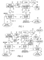
- FIG. 1 is a block diagram illustrating an office environment in which one embodiment of the visually significant bar code system (VSBCS) 10 that does not accept user input can be implemented. The visually significant bar code system (VSBCS) 10 includes an
encoding module 14 for generating a visually significant bar code (VSBC) 20 by utilizing a rendering technique and adecoding module 24 for decoding an acquiredversion 48 of a hard copy (e.g., a firsthard copy 38, acopy 54 of the firsthard copy 38, or a second hard copy 56) that includes a visually significant bar code (VSBC) and for recovering amessage 60 that is specified in the acquiredversion 48. The VSBC 20 can be rendered by utilizing rendering techniques that are well-known to those of ordinary skill in the art. In one embodiment, the VSBC 20 is rendered by utilizing a halftone algorithm to generate ahalftoned VSBC 20. - The
system 10 can communicate with adriving program 15 for providing thelogo 16 and themessage 18 and also communicate with a drivenprogram 70 for utilizing the recoveredmessage 48 for a particular application. - The
encoding module 14 includes a first input for receiving alogo 16, a second input for receiving amessage 18, and an output for generating the visually significant bar code (VSBC) 20. Themessage 18 can be any information that a system designer specifies. -
Logo 16 can be any graphical pattern that has visual significance, which is in sharp contrast to prior 2D bar codes that do not make sense as graphical entities. For example,logo 16 can include, but is not limited to, an actual logo, graphics, a picture, text, a text box, an image, or any other pattern that has visual significance. Exemplary logos can include a company logo, an application logo, or action logo. Exemplary graphics can be frames, button marks, or background. An example of text is a text box having the words "This box contains important data!" The VSBC can be a bar code pattern that is embedded in the graphical design of text, pictures, images, borders, or the background of a document. - The VSBC pattern may be, but is not limited to, a binary image (e.g., a black and white dot pattern), a multi-level image (e.g., a gray-level image), or a multilevel color image that is generated by encoding
module 14. Theencoding module 14 is described in greater detail hereinafter with reference to FIG. 5. - The office environment typically includes office equipment, such as a personal computer (PC) (not shown), a
printer 30 having aprint engine 34, ascanner 40 having ascan engine 44, a facsimile machine (not shown), and acopier 50 for making copies of documents (e.g., copy 54). Theprint engine 34 receives images (e.g., halftoned images) from sources, such as the encodemodule 14, and renders these images to create hard copies, such ashard copy 38 with a first VSBC (L1). Thescan engine 44 receives a hard copy (e.g., ahard copy hard copy 56 with a second VSBC (L2)), generates an acquired version 48 (e.g. a scanned version) of the received hard copy, and provides the acquiredversion 48 to applications, such asdecoding module 24. It is noted that thescanner 40 can be replaced with a digital camera for acquiring a version of the visually significant barcode. Furthermore, thescan engine 44 can be any acquisition engine for capturing the VSBC and providing an acquired version (e.g., a digital representation) of the VSBC. The operation and construction of these office machines and their respective components are generally well known by those of ordinary skill in the art and are not described herein. - In a typical document-handling path, the VSBC along with the remainder of the document is provided to a printer, such as
printer 30. Theprinter 30 then utilizes theprint engine 34 to render a firsthard copy 38 that includes a first VSBC (L1). Thehard copy 38 may then be provided directly to a scanner, such asscanner 44, to generate a scannedversion 48. Alternatively, thehard copy 38 can first be copied once or several times utilizing a copier, such as thecopier 50. Thereafter, the copied version (e.g., copy 54) can be provided to thescanner 44 to generate the scannedversion 48. It is noted that a second hard copy (e.g., hard copy 56) can be generated (e.g., printed or copied) by utilizing a printer (not shown) different fromprinter 30 that is part of a separate office. Also, it is noted that thelogo 16 can vary from application to application (e.g., first VSBC (L1) or second VSBC (L2)) and can be specified by a system designer - The
decoding module 24 receives the acquiredversion 48 and recovers themessage 60 encoded in the acquiredversion 48. For example, if the acquired version corresponds to the firsthard copy 38 or to thecopy 54, then the message in the first VSBC (L1) is recovered as themessage 60. Alternatively, if the acquired version corresponds to the secondhard copy 56 or photocopies thereof, then the message in the second VSBC (L2) is recovered as themessage 60. Themessage 60 is then provided to a drivenapplication 70 that performs one or more pre-determined functions or tasks, examples of which are described in greater detail hereinafter with reference to FIG. 3. - FIG. 2 is a block diagram illustrating an office environment in which an alternative embodiment of the visually significant
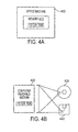
bar code system 10A that accepts user input can be implemented. This visually significant bar code system 10B is similar to thesystem 10A illustrated in FIG. 1, except that thissystem 10A is configured to accept user input. A user can input information to the firsthard copy 38, thecopy 54, or the secondhard copy 56 in the form of marks made by using a writing utensil (e.g., a pencil or pen) as will be explained in greater detail hereinafter with reference to FIG. 3. Thesystem 10A includes a userinput decoding module 26 for decoding the user input, such as (1)user input 64 that may be provided to thehard copy 38; or (2)user input 65 that may be provided to thecopy 54 or the secondhard copy 56. It is noted that the userinput decoding module 26 may be integrated with thedecoding module 24 or be separate from thedecoding module 24 as shown. - In this embodiment, the decoded
user input 66 and themessage 60 specified by the acquiredimage 48 are provided to adecision module 68 that generates one or more signals based on theuser input 66 and themessage 60. These signals can specify or select from one of several options provided by the message. These signals are then provided to one or more driven programs orapplications 70 that perform pre-determined tasks or functions, launch other applications, or control other applications to perform the determined tasks. Examples of such task are described hereinafter with reference to FIG. 3. - It is noted that the driving
application 15 and the drivenapplication 70 can be the same application or different applications. Furthermore, the drivingapplication 15 and the drivenapplication 70 can be incorporated into the visually significant bar code system (VSBCS) 10 or be separate from theVSBC system 10. - FIG. 3 illustrates a
logo 304 of apicture 304A without any user input feature and a logo 304B of a picture having a user input feature. A document 300 (e.g., documents 38, 54, or 56) includes a non-logo portion 302 (e.g., text, images, pictures etc.) and a logo portion 304 (e.g., first VSBC (L1) or second VSBC (L2)) that is can be a VSBC 20. It is noted that theVSBC 20 is provided along with the non-logo portion so that a printer (e.g., the printer 30) can render theentire document 300. Since the rendering and decoding non-logo portions of documents are well known by those of ordinary skill in the art, these operations are not described herein. - The
logo 304 can be apicture 304A without any user input feature or a picture 304B with a user input feature. In either case, the picture (304A or 304B) includes an encodedmessage 308 that can be, but is not limited to, an Internet address (e.g., a World Wide Web address), an electronic mail address, authentication information (e.g., a digital signature or the author or sender of the document), a file name and file location, a facsimile number for "fax-back" applications, or a combination thereof. - One embodiment provides a VSBC to increase the value of documents and to create "living documents". Living documents are those documents that have more information (e.g., encoded messages) than meets the eye or is apparent in viewing the documents. Living documents have encoded messages in the form of VSBCs that can be used to dynamically retrieve additional information (e.g., updated versions of the document), to reduce human intervention, to increase convenience, to improve efficiency in the office, to increase security in the distribution of documents, to increase productivity and to facilitate interaction and communication between people in the office.
- There are numerous applications that use one or more of the types of messages, described above, and encodes these types of messages into documents. It is to be appreciated that there are many other types of messages or information that may be encoded into documents and numerous applications related thereto. The cornerstone of these applications is the VSBCS described herein.
- For example, one application is to use the VSBC to store the file name and the file location (e.g., path to access the document on a server, Web site, etc.). When a document having a VSBC that contains file and file location information is scanned into or otherwise acquired by a personal computer, a Most-Recent Document Application can utilize this information to access the most recent or updated electronic version of the document and launch the document by using a word processing application.
- As can be appreciated, the system can provide significant improvements over the prior art approach that would attempt to convert the scanned version into a text-editable version via some type of OCR. The OCR approach is prone to many errors and mistakes in recognition. In addition, regardless how accurate the OCR utilized, only the version as shown on the physical document can be accessed. If that document has been subsequently revised, there is no mechanism that would allow for the retrieval of the most up-to-date version. This application retrieves the most-current electronic version even if the document has poor quality text that is inadequate for recognition by prior art OCR methods because the file name and file path are encoded in the VSBC.
- Similarly, the encoded name and location of the original electronic version of the document, allows a copier to utilize the original document to be utilized as a copy source instead of having to rely on the document in-hand with the VSBC, which may have been severely degraded in the typical paper handling path. This is an example of a Copy-from-Electronic-Version Application.
- A security application can utilize authentication information encoded in the VSBC for authentication purposes or other secure communication functions. For example, a digital signature can be encoded into the VSBC so that the source of the document can be authenticated.
- In another example, the facsimile number is encoded in the VSBC so that an Automatic Fax-Back Application can utilize the encoded facsimile number to automatically dial the number when the document is fed into a facsimile machine without user intervention. Alternatively, an e-mail address may be encoded in the VSBC so that an Automatic Electronic-Mail Response Application can utilize the encoded electronic mail address to automatically send more information (e.g., a response) via e-mail to the author of the document.
- The picture 304B with a user input feature can include one or more user input forms. For example, a
Check Box Form 314 can be provided for a user to select from one of several options by simply checking the appropriate box. The text message box "Check Appropriate Box" 315 can be a visually significant barcode. In another example, aCircle Selection Form 318 can be provided for a user to select from one of several options by simply circling the appropriate selection. The text message box "Circle Desired Option" 319 can be a visually significant barcode. In yet another example, a Fill-InForm 324 can be provided for a user to fill in information requested by the form. The text message box "Fill In" 325 can be a visually significant barcode. - Each of these forms request
user input 330, such as a check mark, a circle, or text input. Theuser input 330 can then be decoded by the userinput decode module 26 to recover the user input. Thereafter, thedecision module 68 utilizes the user input in conjunction with the recovered message to select one of several available functions or tasks, and the drivenapplication 70 for performing the selected tasks can be launched. For example, the user input can be utilized to arbitrate between different messages encoded in the different visually significant text boxes. In the automatic e-mail response application, the user input and the different visually significant text boxes can be utilized to (1) reply only to the sender or (2) to reply to all recipients including the sender. - The
VSBC system VSBC system VSBC system - FIG. 4A is a block diagram illustrating an
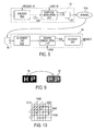
office machine 400 in which theVSBC system office machine 400 includes amemory 410 in which theVSBCS office machine 400 may be a personal computer (PC). If this is the case, the PC can be coupled to a printer, scanner, an all-in-one machine or other peripheral machine. It is noted that theVSBCS - Alternatively, the office machine can be an all-in-one office machine (e.g., an integrated scanner, printer, and facsimile machine) or any rendering machine.
- FIG. 4B is a block diagram illustrating a computer-
readable medium 420 in which theVSBC system readable medium 420 may be afloppy disk 440, a compact disc (CD) 430, or other computer-readable medium, etc. As can be appreciated, theVSBC system - FIG. 5 is a block diagram illustrating in greater detail the
encoding module 14 and thedecoding module 24 of FIG. 1 and FIG. 2. Theencoding module 14 includes anencoder 500 for receiving amessage 18 and generating an encodedmessage 504 based on themessage 18.Encoding module 14 also includes agraphic modulation unit 510 for receiving thelogo 16 and the encodedmessage 504 and based thereon, generates theVSBC 20. TheVSBC 20 can be a specific pattern. In thechannel 514, the VSBC 20 can be rendered directly on a document or incorporated into a document and rendered thereon. - Preferably, the visually significant two-dimensional bar codes are graphical patterns composed, usually though not necessarily, of dots. The visually significant bar codes are rendered, usually though not necessarily, using two-toned dots (e.g. black dots on a white background), and occupy, usually though not necessarily, a rectangular area. The visually significant bar codes can incorporate various registration and fiducial marks, which are generally well known to those of ordinary skill in the art, for enabling automated identification and accurate registration of the bar code, which may be read in arbitrary orientations. In addition, the visually significant bar code system can employ various error correcting codes, which are generally well known to those of ordinary skill in the art, for reliable automated retrieval of the bar codes.
- The steps carried out by encoding
module 14 to process themessage 18 and thelogo 16 to generate the VSBC 20 are described in greater detail hereinafter with reference to FIG. 6. -
Channel 514 represents a typical office document-handling path for hard copies by standard office equipment. For example, a hard copy can be printed, photocopied, and scanned. It is understood that one or more of these standard office handling steps can be carried out by multi-functional equipment. Since the barcode pattern is subject to noise and office document degradation (e.g., folds, stains, marks, and staples) in thechannel 514, a standard cleaning process to address the noise and degradation of barcode pattern can be employed. - The steps carried out by the
decoding module 24 to recover themessage 60 from the acquiredimage 48 are described in greater detail hereinafter with reference to FIG. 8. - FIG. 6 illustrates a method of encoding a
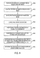
message 18 into a visuallysignificant barcode 20 according to one embodiment of the present invention. Instep 600, themessage 18 and thelogo 16 are received. Themessage 18 can also be compressed by utilizing well known compression techniques in this step. For certain applications, such as universal resource locators (URLs), a tailored or customized compression scheme may be preferable. - In
step 610, the compressed message is encoded by utilizing an error correction code with an output alphabet L to generate a message encoded in a sequence of Q symbols. This encoding step provides robustness to errors in thechannel 514. For example, a standard 16 → 31 bit BCH code that corrects for three errors, where L = 4 (2 bits) can be used. - In
step 620, thelogo 16, which can be an M x N pixel image, is partitioned in a plurality of image matrices. In one example, K is equal to two (2), and M and N (i.e., the size of the logo 16) are even values (e.g., N = 80 and M = 40). The values of K, M and N can be modified and predetermined by a system designer to suit a particular application. - In
step 630, an image area corresponding to R logo matrices is used for pre-defined fiducial marks. For example, the four corners of the image can be reserved for fiducial marks. In each corner, an area of 4 x 4 pixels (2 x 2 matrices) can be designated for fiducial marks. The fiducial marks can be the whole area rendered white, except for an isolated location in each corner that is set apart or separate from adjacent matrices, which is rendered black. The upper-left fiducial mark, for example, can be all white except for the upper-left pixel, which is rendered black. It is preferable that the pattern for the fiducial mark be as robust to channel noise as possible. Since dots may be blurred or move relative to each other due to noise in thechannel 514, this pattern ensures that the black fiducial dots do not merge with neighboring dots, and instead stand out clearly on a white background. Various other fiducial patterns can be utilized depending on the particular types of noise in a particular channel of interest. - In
step 640, the remaining logo matrices (i.e., P = M x Nl(K x K) - R logo matrices) are converted to K x K binary barcode matrices by utilizing one of a predefined set of L distinct maps (e.g., halftoning algorithms) based on a corresponding symbol in the coded message. In one example, there are 784 remaining image-matrices (based on N =80 and M =40) that can be ordered in raster scan. The 784 image matrices can accommodate slightly more than 25 batches of 31 matrices (Q = 25 × 31= 775). It is important to note that P should be greater than Q. Each batch codes two batches of 16 input bits: (1) one batch for the BCH MS bits, and (2) the other batch for the BCH LS bits. Thus, for the parameters specified above, the barcode can encode 25 x 16 x 2 = 800 bits of information. - FIG. 7A illustrates an exemplary implementation of
encoding step 640 of FIG. 6 in accordance with one embodiment of the present invention. Thelogo 16 includes a plurality of pixels having one of two different gray levels: 25% and 75%. For example,pixels pixel 708 has a 75% gray level. - Referring to FIG. 7B, for those pixels in the
logo 16 that have a 25% gray level, one of the four bar code matrices in the first row is used to render the based on the data to be encoded. For example, if the data to be encoded is "11",pixel 704 is rendered by utilizing thebar code matrix 710. Similarly, if the data to be encoded is "01",pixel 706 is rendered by utilizing thebar code matrix 730. Similarly, for those pixels in thelogo 16 that have a 75% gray level, one of the four bar code matrices in the second row is used to render the based on the data to be encoded. For example, if the data to be encoded is "00",pixel 708 is rendered by utilizing thebar code matrix 720. - Although this implementation utilizes two gray levels, 25% and 75%, it is noted that the system can be extended to include multiple levels can be utilized to suit a particular application. In addition, it can be extended to pixels of different colors.
- Alternatively, the remaining image-matrices can be ordered with interleaving methods that are known in the art, to provide robustness to burst-type degradations expected from stains, marks, or systematic printer/scanner distortions. The K x K binary barcode matrices can then be sent to a printer for printing onto a hard copy, such as a piece of paper.
- There are many rendering methodologies from which one can choose the L distinct maps. For example, when halftoning algorithms are selected as the L distinct maps, there are many type of halftone methodologies one can choose from. In an exemplary implementation a fixed-halftone-pattern halftoning method is utilized. This method specifies that the image be a 2-tone image. If black is 0, and white is 1, the bright tone b, and the dark tone d, are such that d = 1 - b. Also, the L halftoning algorithms correspond to L distinct K x K pattern-matrices, where each pattern matrix contains b • K x K black dots on white background. However, it is noted that other well-known halftoning methods, such as cluster dithering, disperse dithering (e.g., blue noise), and error diffusion methods can be utilized. When an error diffusion algorithm is employed, one can select from many different methods to diffuse the error. Similarly, when a disperse dithering algorithm is utilized, one can select from many methods to define the dither matrices (also known as screens) of various sizes.
- Given a logo-matrix, and the selected pattern-matrix, the resulting barcode-matrix contains the pattern matrix values in the places corresponding to the bright pixels in the logo-matrix, and their complementary otherwise.
- In this embodiment, the dots are preferably rendered as square dots at 120 dots-per-inch (dpi). It is noted that larger dots are more robust to channel degradations, but smaller dots enable more information on the same area of the paper. The dots can be rendered at a dpi higher than 120dpi as long as acceptable error resilience can be assured.
- It is noted that the size of the dots can be varied according to intensity. An example of varying the size of dots based on intensity is to make the black dots slightly larger than the white dots. It is also noted that the size of the dots can be varied according to neighborhood. An example of varying the size of dots based on neighborhood is to make minority colored dots larger.
- FIG. 9 illustrates an
exemplary logo 16 andmessage 18 that are used to generate acorresponding VSBC 20 by the disclosed encoding method. - The
image 48 acquired by thescanner 40 and introduced to thedecoding module 24 is a degraded version of the original bar code-image. These degradations are attributed to thechannel 514, namely, the printing and scanning processes, and potential office type degradations, such as copying, stains, folds, staples, and marks. - FIG. 8 illustrates a method of decoding a visually significant barcode according to one embodiment of the present invention. In
step 800, the acquired image is received, for example, from the scanner. Instep 810, the bar code image is located in the received image. For example, the received image can be a whole page of information, whereas the barcode image can be limited to a barcode zone, which may be a portion of the whole page. In one embodiment, the barcodes are located roughly at a same predetermined location in the acquired image and are surrounded by white pixels. This predetermined location is referred to herein as the barcode-zone. Alternatively, the barcodes can be disposed in varying locations on a page, as background, or as a frame for the page. When barcodes are disposed in such a manner, a barcode locating procedure can be utilized to locate the barcode image on the page. - In
step 820, the fiducial marks are detected. The configuration of these fiducial marks indicates the type of global deformation introduced by the channel. In one embodiment, the fiducial marks are detected by using a zigzag scan. - FIG. 10 illustrates a
zigzag scan 1000 that can be used instep 820 to detect the fiducial marks. Thezigzag scan 1000 begins at the upper-leftcorner 1010. The firstdark pixel 1020 of each scan (requires a threshold) is detected and considered to be a part of the corresponding fiducial pixel. The firstdark pixel 1020 is also used as an anchor pixel for that mark (red dot in Figure 5). Next, a flood-fill algorithm, which is known in the art, locates all thedark pixels 1030 connected to these anchors. Thecenters 1040 of the fiducial marks are then computed as the average (center of mass) of the pixels of each mark. An advantage of this zigzag scan is that it enables a robust detection of the anchor points even in the presence of significant rotations. This scan can be repeated at each corner of the barcode. - In
step 830, viewing transformation distortions (e.g., translation, rotation, and affine) are corrected. By setting the center of the coordinate system to be ten pixels above and ten pixels to the left of the center of the upper-left fiducial mark, translation problems can be eliminated. The relative rotation of the center of the upper-right fiducial mark is then determined, and the image is rotated back accordingly. - Next, the skew factor, which is the horizontal translation of the centers of lower marks relative to the horizontal translation of the centers of the upper mark, is determined. If a skew is detected, the image is corrected for the detected skew. These transformation procedures can be implemented with standard procedures known in the computer vision and image processing areas.
- In one embodiment, bilinear interpolation is utilized although other interpolators can be used. It is noted that a single affine transformation can be utilized to correct for both the rotation and the skew.
- The four fiducial marks enable correction of global transformations with up to eight degrees of freedom. In this embodiment, there are four degrees of freedom (two - translation, one - rotation, and one- skew).
- In
step 840, the acquired barcode image is partitioned into a plurality of sub-images that can be arranged in a rectangular array, where each sub-image corresponds to a single barcode matrix. Step 830 provides a rectangular image. In one embodiment, the step of partitioning the acquired barcode image involves the steps of measuring the image and slicing the image into rectangular sub-images. In our case M / K = 20, and N / K = 40 so each rectangular sub-image had the dimensions of 20 x 40. - In
step 850, each sub-image is compared against the set of L possible barcode-matrices (i.e., the outputs of the L distinct maps (e.g., halftoning algorithms) given the corresponding image), When the halftone patterns of FIG. 7B are used, and the logo design is required to have a constant brightness in every logo-matrix, four vector products can be applied to every sub-image. The four vectors are Gaussian profiles that are each centered at the center of a quadrant of the sub-image. For dark sub-images, the pattern of FIG. 7B corresponds to the quadrant having the maximal value, and for bright sub-images, the pattern corresponds to the quadrant having the minimal value. This approach is also known as the matched filter approach in the image processing arts. - In
step 860, a best match is selected to represent the sub-image in a sequence of P symbols over {1,2,... L}. It is noted that any maximum-likelihood-type of detector or any other match estimator can be utilized to determine which of the L possible maps (e.g., halftones) is the most likely to have produced the corresponding sub-image. Preferably, the best match is performed on a group of sub-images. - In
step 870, the (possibly erroneous) sequence that was originally coded with an error-correcting code is decoded, thereby eliminating the effect of possible errors due to the degradations of the channel. The corresponding standard BCH error correction may be performed followed by the appropriate re-ordering of the bits. - In step 880, the sequence is decompressed to give the original message.
- The present invention provides a barcode pattern with visual significance, thereby increasing its acceptance and use in the business environment and even the home environment. Whereas the prior art bar codes were limited to impersonal commercial and industrial applications, the barcode pattern with visual significance changes the sentimental value attached the use of barcodes in more personal contexts from unfavorable to favorable.
- In addition, different applications can easily incorporate the visually significant barcode pattern and different variations thereof (e.g., different logos or other graphics), thereby enabling a user to customize or personalize the barcode pattern.
- Moreover, the system utilizes techniques, such as error correction and the use of fiducial marks, to make the visually significant barcode pattern robust to imperfections and noise in the hardcopy-handling channel. For example, the barcode pattern is robust to consecutive photocopying by common office copiers (e.g., analog and digital copiers). Also, the barcode pattern is resilient to common office document degradations, such as folds, stains, marks, and staples.
- Furthermore, the visually significant barcode pattern can be printed by and read by standard office equipment, such as printers, scanners, copiers, and multi-functional equipment.
Claims (11)
- A visually significant barcode system (10) including:an encoding module (14) configured to receive a message (18) and a base image (16) and to modulate the base image (16) with a graphical encoding of the message to produce a visually significant barcode (20) having the message encoded therein and having a pattern which is visually understandable to a person, the encoding module being operable:to divide the base image (16) into multiple image areas (704-708),to segment image areas to be encoded into multiple groups (704, 706; 708) based on pixel values in the image areas to be encoded, andto encode the segmented image areas with sets of two-dimensional code patterns (710-730) to graphically encode the message in the visually significant barcode (20), wherein each set of code patterns encodes a respective corresponding group of image areas.
- A system as in claim 1, including:a print engine (34) coupled to the encoding module for receiving the visually significant barcode and based thereon for rendering a hard copy of the visually significant barcode.
- A system as in claim 2, wherein the print engine utilizes a halftone algorithm to render the hard copy of the visually significant barcode.
- A system as in any preceding claim, including:a decoding module (24) for receiving an acquired version (48) of the visually significant barcode and based thereon for recovering a message (60) encoded therein.
- A system as in claim 4, wherein the encoding module and the decoding module are embodied on a medium.
- A system as in claim 5, wherein the media is incorporated in an office machine in the form of a memory.
- A system as in claim 4, 5 or 6, including:an acquisition engine (44) coupled to the decoding module for receiving a hard copy having a visually significant barcode and, based thereon, for generating the acquired version of the visually significant barcode.
- A method of generating a visually significant barcode comprising:receiving an M x N pixel image (600);receiving a message having a plurality of bit patterns (600);partitioning the M x N pixel image into a plurality of image matrices (620); andconverting the image matrices to K x K barcode matrices by utilizing one of a predetermined set of L distinct maps; wherein the selection of the particular map is based on a corresponding symbol of the message (640).
- A method of decoding a visually significant barcode comprising:receiving the barcode image (800);partitioning the barcode image into a plurality of sub-images (840);comparing each-sub-image with a set of L possible barcode matrices (850); anddecoding a message based on a match estimation of each sub-image to each one of the L possible barcode matrices in a sequence of P symbols over {1, 2, ...L} (860).
- A system for generating a visually significant barcode comprising:means for receiving an M x N pixel image (600);means for receiving a message having a plurality of bit patterns (600);means for partitioning the M x N pixel image into a plurality of image matrices (620); andmeans for converting the image matrices to K x K barcode matrices by utilizing one of a predetermined set of L distinct maps; wherein the selection of the particular map is based on a corresponding field of the message (640).
- A system for decoding a visually significant barcode comprising:means for receiving the barcode image (800);means for partitioning the barcode image into a plurality of sub-images (840);means for comparing each-sub-image with a set of L possible barcode matrices (850); andmeans for decoding a message based on a match estimation of each sub-image to each one of the L possible barcode matrices in a sequence of P symbols over {1, 2, ...L} (860).
Applications Claiming Priority (2)
| Application Number | Priority Date | Filing Date | Title |
|---|---|---|---|
| US579070 | 2000-05-25 | ||
| US09/579,070 US6751352B1 (en) | 2000-05-25 | 2000-05-25 | Method and apparatus for generating and decoding a visually significant barcode |
Publications (3)
| Publication Number | Publication Date |
|---|---|
| EP1158456A2 EP1158456A2 (en) | 2001-11-28 |
| EP1158456A3 EP1158456A3 (en) | 2002-05-08 |
| EP1158456B1 true EP1158456B1 (en) | 2007-01-10 |
Family
ID=24315450
Family Applications (1)
| Application Number | Title | Priority Date | Filing Date |
|---|---|---|---|
| EP01304584A Expired - Lifetime EP1158456B1 (en) | 2000-05-25 | 2001-05-24 | Barcode system |
Country Status (5)
| Country | Link |
|---|---|
| US (2) | US6751352B1 (en) |
| EP (1) | EP1158456B1 (en) |
| JP (1) | JP4883662B2 (en) |
| CN (1) | CN1211754C (en) |
| DE (1) | DE60125862T2 (en) |
Cited By (7)
| Publication number | Priority date | Publication date | Assignee | Title |
|---|---|---|---|---|
| WO2009058268A1 (en) * | 2007-10-31 | 2009-05-07 | Ncr Corporation | Lumid barcode format |
| US7684618B2 (en) | 2002-10-31 | 2010-03-23 | Microsoft Corporation | Passive embedded interaction coding |
| US7729539B2 (en) | 2005-05-31 | 2010-06-01 | Microsoft Corporation | Fast error-correcting of embedded interaction codes |
| US7817816B2 (en) | 2005-08-17 | 2010-10-19 | Microsoft Corporation | Embedded interaction code enabled surface type identification |
| US7826074B1 (en) | 2005-02-25 | 2010-11-02 | Microsoft Corporation | Fast embedded interaction code printing with custom postscript commands |
| US7920753B2 (en) | 2005-05-25 | 2011-04-05 | Microsoft Corporation | Preprocessing for information pattern analysis |
| US8156153B2 (en) | 2005-04-22 | 2012-04-10 | Microsoft Corporation | Global metadata embedding and decoding |
Families Citing this family (74)
| Publication number | Priority date | Publication date | Assignee | Title |
|---|---|---|---|---|
| US7387253B1 (en) | 1996-09-03 | 2008-06-17 | Hand Held Products, Inc. | Optical reader system comprising local host processor and optical reader |
| US6938017B2 (en) * | 2000-12-01 | 2005-08-30 | Hewlett-Packard Development Company, L.P. | Scalable, fraud resistant graphical payment indicia |
| US7075676B2 (en) * | 2000-12-19 | 2006-07-11 | Sharp Laboratories Of America, Inc. | Method for attaching file as a barcode to the printout |
| US7028009B2 (en) * | 2001-01-17 | 2006-04-11 | Contentguardiholdings, Inc. | Method and apparatus for distributing enforceable property rights |
| JP4759844B2 (en) * | 2001-05-18 | 2011-08-31 | ソニー株式会社 | Information providing apparatus and method, information processing apparatus and method, recording medium, and program |
| US7386129B2 (en) * | 2001-05-30 | 2008-06-10 | Digeo, Inc. | System and method for multimedia content simulcast |
| US7093277B2 (en) * | 2001-05-30 | 2006-08-15 | Digeo, Inc. | System and method for improved multi-stream multimedia transmission and processing |
| AU2002345270B2 (en) * | 2001-07-11 | 2007-11-29 | Ecole Polytechnique Federale De Lausanne | Images incorporating microstructures |
| US7463737B2 (en) | 2001-08-15 | 2008-12-09 | Digeo, Inc. | System and method for conditional access key encryption |
| ES2295457T3 (en) * | 2001-12-05 | 2008-04-16 | Rodenstock Gmbh | METHOD TO MARK OBJECTS. |
| US6915020B2 (en) * | 2001-12-19 | 2005-07-05 | Hewlett-Packard Development Company, L.P. | Generating graphical bar codes by halftoning with embedded graphical encoding |
| AU2003205539A1 (en) * | 2002-01-21 | 2003-07-30 | Tracexpert A/S | Method for identification and registration of received items before storage in a factory stock |
| US7206431B2 (en) * | 2002-02-22 | 2007-04-17 | Symbol Technologies, Inc. | System and method for generating and verifying a self-authenticating document |
| US7028902B2 (en) | 2002-10-03 | 2006-04-18 | Hewlett-Packard Development Company, L.P. | Barcode having enhanced visual quality and systems and methods thereof |
| US7009594B2 (en) | 2002-10-31 | 2006-03-07 | Microsoft Corporation | Universal computing device |
| US7430497B2 (en) | 2002-10-31 | 2008-09-30 | Microsoft Corporation | Statistical model for global localization |
| US7502507B2 (en) | 2002-10-31 | 2009-03-10 | Microsoft Corporation | Active embedded interaction code |
| US7116840B2 (en) | 2002-10-31 | 2006-10-03 | Microsoft Corporation | Decoding and error correction in 2-D arrays |
| JP4181881B2 (en) * | 2003-01-22 | 2008-11-19 | キヤノン株式会社 | Image processing apparatus and method |
| US7274831B2 (en) | 2003-04-03 | 2007-09-25 | Microsoft Corporation | High quality anti-aliasing |
| EP1668446A2 (en) * | 2003-09-05 | 2006-06-14 | Oliver Foehr | Method, device and system for a machine-readable code enabled device enabling e-commerce transactions |
| US20060064308A1 (en) * | 2004-09-02 | 2006-03-23 | Oliver Foehr | Method, device and system for a machine-readable code enabled device enabling E-commerce transactions |
| US8363282B2 (en) | 2003-10-31 | 2013-01-29 | Hewlett-Packard Development Company, L.P. | Halftone screening and bitmap based encoding of information in images |
| JP4534561B2 (en) * | 2004-04-13 | 2010-09-01 | 株式会社日立製作所 | Reliability judgment method for printed matter |
| US8316068B2 (en) * | 2004-06-04 | 2012-11-20 | Telefonaktiebolaget Lm Ericsson (Publ) | Memory compression |
| US7823784B2 (en) | 2004-06-14 | 2010-11-02 | Fujifilm Corporation | Barcode creation apparatus, barcode creation method and program |
| WO2006009565A2 (en) * | 2004-06-22 | 2006-01-26 | United States Postal Service | Method and system for providing a barcode image over a network |
| US7304585B2 (en) * | 2004-07-02 | 2007-12-04 | Nokia Corporation | Initiation of actions with compressed action language representations |
| EP1653395A3 (en) * | 2004-10-01 | 2006-05-10 | Axalto SA | Protection method for a portable personal object |
| US7578436B1 (en) | 2004-11-08 | 2009-08-25 | Pisafe, Inc. | Method and apparatus for providing secure document distribution |
| KR100636197B1 (en) * | 2004-11-26 | 2006-10-19 | 삼성전자주식회사 | Method and apparatus for printing image using barcode firmware information |
| WO2006089247A2 (en) * | 2005-02-16 | 2006-08-24 | Pisafe, Inc. | Method and system for creating and using redundant and high capacity barcodes |
| US20060210192A1 (en) * | 2005-03-17 | 2006-09-21 | Symagery Microsystems Inc. | Automatic perspective distortion detection and correction for document imaging |
| US7747544B2 (en) * | 2005-12-07 | 2010-06-29 | Pitney Bowes Inc. | Meter tape with location indicator used for unique identification |
| WO2007075719A2 (en) | 2005-12-16 | 2007-07-05 | Pisafe, Inc. | Method and system for creating and using barcodes |
| US7909256B2 (en) * | 2005-12-31 | 2011-03-22 | Motorola Mobility, Inc. | Method and system for automatically focusing a camera |
| JP4758238B2 (en) * | 2006-01-31 | 2011-08-24 | 株式会社リコー | Data processing apparatus, data processing method, program, and recording medium |
| US8150163B2 (en) * | 2006-04-12 | 2012-04-03 | Scanbuy, Inc. | System and method for recovering image detail from multiple image frames in real-time |
| US8166003B2 (en) * | 2006-05-05 | 2012-04-24 | Microsoft Corporation | Permission-based document server |
| US7627191B2 (en) * | 2006-08-14 | 2009-12-01 | Xerox Corporation | Image manipulation |
| US8116550B2 (en) * | 2006-12-20 | 2012-02-14 | Cytyc Corporation | Method and system for locating and focusing on fiducial marks on specimen slides |
| JP5257568B2 (en) * | 2007-07-20 | 2013-08-07 | 富士ゼロックス株式会社 | Image forming apparatus, image forming system, and image forming program |
| GB2451437B (en) * | 2007-07-27 | 2012-11-14 | Hewlett Packard Development Co | Content encoder and decoder and methods of encoding and decoding content |
| US8086502B2 (en) * | 2008-03-31 | 2011-12-27 | Ebay Inc. | Method and system for mobile publication |
| JP5385388B2 (en) | 2008-08-04 | 2014-01-08 | エフ.ホフマン−ラ ロシュ アーゲー | Encoding method for encoding medical articles |
| US8865293B2 (en) | 2008-12-15 | 2014-10-21 | 3M Innovative Properties Company | Optically active materials and articles and systems in which they may be used |
| US8825660B2 (en) | 2009-03-17 | 2014-09-02 | Ebay Inc. | Image-based indexing in a network-based marketplace |
| BR112012007870A2 (en) | 2009-10-08 | 2020-08-18 | 3M Innovative Properties Company | retroreflective lamination, license plate and optical character recognition system |
| JP5671047B2 (en) * | 2009-10-16 | 2015-02-18 | スリーエム イノベイティブ プロパティズ カンパニー | A prismatic retroreflective sheet with reduced infrared retroreflectivity |
| JP4629788B1 (en) | 2009-11-20 | 2011-02-09 | 進 辻 | Article with display code, display code generation device, and information transmission method |
| US8430301B2 (en) * | 2009-11-23 | 2013-04-30 | Konica Minolta Laboratory U.S.A., Inc. | Document authentication using hierarchical barcode stamps to detect alterations of barcode |
| US8593697B2 (en) * | 2010-01-11 | 2013-11-26 | Hewlett-Packard Development Company, L.P. | Document processing |
| JP5609469B2 (en) * | 2010-09-15 | 2014-10-22 | 富士ゼロックス株式会社 | Image processing apparatus, identification apparatus, electronic writing instrument, and program |
| US9947050B1 (en) | 2011-03-21 | 2018-04-17 | Allstate Insurance Company | Claims adjuster allocation |
| WO2012177249A1 (en) | 2011-06-22 | 2012-12-27 | Hewlett-Packard Development Company, L.P. | Systems and methods for tracing the source of printed pages |
| US8632013B2 (en) * | 2011-08-09 | 2014-01-21 | Intellectual Ventures Fund 83 Llc | Information retrieval using decoded machine-readable optical codes |
| WO2013048459A1 (en) | 2011-09-30 | 2013-04-04 | Hewlett-Packard Development Company, L. P. | Decision device and method thereof |
| JP6576240B2 (en) * | 2012-03-30 | 2019-09-18 | スリーエム イノベイティブ プロパティズ カンパニー | Retroreflective article having machine-readable code |
| US8948445B2 (en) | 2012-05-03 | 2015-02-03 | The Hong Kong University Of Science And Technology | Embedding visual information in a two-dimensional bar code |
| US9170874B2 (en) | 2012-07-17 | 2015-10-27 | Hewlett-Packard Development Company, L.P. | Providing a potential solution |
| WO2014021819A1 (en) * | 2012-07-30 | 2014-02-06 | Hewlett-Packard Development Company, L.P. | Document copy with data-bearing halftone image |
| CN104021409B (en) * | 2013-02-28 | 2017-03-01 | 国际商业机器公司 | The method and apparatus of automatic conversion mark and the automatic method reading mark |
| CN104525487B (en) * | 2014-12-29 | 2016-11-02 | 施展 | A kind of intelligence secrecy postal delivery transceiver protecting personal information during postal delivery and method of work thereof |
| US10885587B1 (en) | 2015-05-05 | 2021-01-05 | Allstate Insurance Company | Catastrophe resource system |
| US10896340B2 (en) | 2015-08-21 | 2021-01-19 | 3M Innovative Properties Company | Encoding data in symbols disposed on an optically active article |
| CN109476262B (en) | 2016-05-13 | 2022-04-26 | 3M创新有限公司 | Anti-counterfeit detection of optically active articles using security elements |
| CN109791623B (en) | 2016-09-28 | 2022-06-28 | 3M创新有限公司 | Article having a substrate including a physical surface and method of construction thereof |
| CN109791624B (en) | 2016-09-28 | 2022-06-07 | 3M创新有限公司 | Machine-readable article comprising a masked elastic optical code |
| JP2019534507A (en) | 2016-09-28 | 2019-11-28 | スリーエム イノベイティブ プロパティズ カンパニー | Multidimensional optical code including static data and dynamic lookup data optical element sets |
| US20180350021A1 (en) | 2017-03-16 | 2018-12-06 | Sawar PEDAWI | Global address system and method |
| US20180268369A1 (en) * | 2017-03-16 | 2018-09-20 | Sarwar PEDAWI | Global address system and method |
| US11429803B2 (en) | 2018-03-27 | 2022-08-30 | 3M Innovative Properties Company | Identifier allocation for optical element sets in machine-read articles |
| US10997448B2 (en) * | 2019-05-15 | 2021-05-04 | Matterport, Inc. | Arbitrary visual features as fiducial elements |
| US11580064B2 (en) | 2021-06-22 | 2023-02-14 | Cypherpunk Llc | Methods and systems for encoding URI for arbitrary payload data based on alphanumeric encoding methods |
Family Cites Families (79)
| Publication number | Priority date | Publication date | Assignee | Title |
|---|---|---|---|---|
| US4637051A (en) | 1983-07-18 | 1987-01-13 | Pitney Bowes Inc. | System having a character generator for printing encrypted messages |
| JPS62111367A (en) | 1985-11-11 | 1987-05-22 | Hitachi Ltd | Bar code reader |
| US4901073A (en) | 1986-12-04 | 1990-02-13 | Regent Of The University Of California | Encoder for measuring the absolute position of moving elements |
| US4822986A (en) | 1987-04-17 | 1989-04-18 | Recognition Equipment Incorporated | Method of detecting and reading postal bar codes |
| US4924078A (en) | 1987-11-25 | 1990-05-08 | Sant Anselmo Carl | Identification symbol, system and method |
| US5195123A (en) * | 1988-11-23 | 1993-03-16 | Clement Richard J | Radiograph identification method and device |
| US5304786A (en) * | 1990-01-05 | 1994-04-19 | Symbol Technologies, Inc. | High density two-dimensional bar code symbol |
| US5075862A (en) | 1989-12-26 | 1991-12-24 | Pitney Bowes Inc. | System for printing value indicia with diagrammatic data representation |
| US5337361C1 (en) | 1990-01-05 | 2001-05-15 | Symbol Technologies Inc | Record with encoded data |
| CA2039652C (en) | 1990-05-30 | 1996-12-24 | Frank Zdybel, Jr. | Hardcopy lossless data storage and communications for electronic document processing systems |
| US5060980A (en) | 1990-05-30 | 1991-10-29 | Xerox Corporation | Form utilizing encoded indications for form field processing |
| US5091966A (en) | 1990-07-31 | 1992-02-25 | Xerox Corporation | Adaptive scaling for decoding spatially periodic self-clocking glyph shape codes |
| US5120940A (en) | 1990-08-10 | 1992-06-09 | The Boeing Company | Detection of barcodes in binary images with arbitrary orientation |
| US6076733A (en) * | 1993-11-24 | 2000-06-20 | Metrologic Instruments, Inc. | Web-based system and method for enabling a viewer to access and display HTML-encoded documents located on the world wide web (WWW) by reading URL-encoded bar code symbols printed on a web-based information resource guide |
| US5315098A (en) | 1990-12-27 | 1994-05-24 | Xerox Corporation | Methods and means for embedding machine readable digital data in halftone images |
| US5818970A (en) | 1991-04-26 | 1998-10-06 | Canon Kabushiki Kaisha | Image encoding apparatus |
| US5541396A (en) | 1991-07-19 | 1996-07-30 | Rentsch; Frederic | Method of representing binary data |
| US5339170A (en) | 1991-12-31 | 1994-08-16 | Xerox Corporation | Image processing system and method employing hybrid filtering to provide improved reconstruction of continuous tone images from halftone screen-structured images |
| US5329105A (en) | 1992-08-10 | 1994-07-12 | United Parcel Service Of America, Inc. | Method and apparatus for determining the width of elements of bar code symbols |
| US5535020A (en) | 1992-10-15 | 1996-07-09 | Digital Equipment Corporation | Void and cluster apparatus and method for generating dither templates |
| US5527407A (en) * | 1992-12-30 | 1996-06-18 | The Goodyear Tire & Rubber Company | Apparatus and method for marking a rubber article with a message readable by a light scanning device |
| EP0682795A1 (en) | 1993-02-02 | 1995-11-22 | Label Vision Systems, Inc. | Method and apparatus for decoding bar code data from a video signal and applications thereof |
| US6983051B1 (en) | 1993-11-18 | 2006-01-03 | Digimarc Corporation | Methods for audio watermarking and decoding |
| US6345104B1 (en) * | 1994-03-17 | 2002-02-05 | Digimarc Corporation | Digital watermarks and methods for security documents |
| US5459307A (en) | 1993-11-30 | 1995-10-17 | Xerox Corporation | System for storage and retrieval of digitally encoded information on a medium |
| US5606507A (en) | 1994-01-03 | 1997-02-25 | E-Stamp Corporation | System and method for storing, retrieving and automatically printing postage on mail |
| US5591956A (en) | 1995-05-15 | 1997-01-07 | Welch Allyn, Inc. | Two dimensional data encoding structure and symbology for use with optical readers |
| US5523552A (en) | 1994-10-19 | 1996-06-04 | Symbol Technologies, Inc. | Method and apparatus to scan randomly oriented two-dimensional bar code symbols |
| US5513563A (en) | 1994-11-14 | 1996-05-07 | Pitney Bowes Inc. | Indicia security via variable dot size |
| JP2952170B2 (en) | 1994-12-16 | 1999-09-20 | オリンパス光学工業株式会社 | Information reproduction system |
| US6032861A (en) | 1995-01-03 | 2000-03-07 | Lemelson; Jerome H. | Method and apparatus for encoding and decoding bar codes with primary and secondary information and method of using such bar codes |
| US5661284A (en) | 1995-03-13 | 1997-08-26 | Albert J. Freeman | Commercial transaction system |
| JPH0944592A (en) | 1995-05-23 | 1997-02-14 | Olympus Optical Co Ltd | Information reproduction system |
| US5706099A (en) | 1995-06-05 | 1998-01-06 | Xerox Corporation | Method and apparatus for generating serpentine halftone images |
| US5710636A (en) * | 1995-06-05 | 1998-01-20 | Xerox Corporation | Method and apparatus for generating halftone images having human readable patterns formed therein |
| US6311214B1 (en) | 1995-07-27 | 2001-10-30 | Digimarc Corporation | Linking of computers based on optical sensing of digital data |
| JPH0981711A (en) | 1995-09-20 | 1997-03-28 | Olympus Optical Co Ltd | Information recording medium, information reproduction system, and information recording the system |
| US5819240A (en) | 1995-10-11 | 1998-10-06 | E-Stamp Corporation | System and method for generating personalized postage indica |
| US5801944A (en) | 1995-10-11 | 1998-09-01 | E-Stamp Corporation | System and method for printing postage indicia directly on documents |
| US6151590A (en) | 1995-12-19 | 2000-11-21 | Pitney Bowes Inc. | Network open metering system |
| US5969325A (en) | 1996-06-03 | 1999-10-19 | Accu-Sort Systems, Inc. | High speed image acquisition system and method of processing and decoding barcode symbol |
| US5710814A (en) | 1996-07-23 | 1998-01-20 | Cheyenne Property Trust | Cryptographic unit touch point logic |
| US5799112A (en) | 1996-08-30 | 1998-08-25 | Xerox Corporation | Method and apparatus for wavelet-based universal halftone image unscreening |
| US5946415A (en) | 1996-10-24 | 1999-08-31 | The United States Of America As Represented By The Secretary Of The Army | Method and apparatus to process drawing images |
| US5974147A (en) | 1996-11-07 | 1999-10-26 | Pitney Bowes Inc. | Method of verifying unreadable indicia for an information-based indicia program |
| US6064738A (en) | 1996-12-10 | 2000-05-16 | The Research Foundation Of State University Of New York | Method for encrypting and decrypting data using chaotic maps |
| US5982896A (en) | 1996-12-23 | 1999-11-09 | Pitney Bowes Inc. | System and method of verifying cryptographic postage evidencing using a fixed key set |
| US5871288A (en) | 1996-12-24 | 1999-02-16 | Pitney Bowes Inc. | Method for customer selectable module size for an information based indicia |
| JPH10198774A (en) * | 1997-01-09 | 1998-07-31 | Olympus Optical Co Ltd | Medium and device for information recording |
| US5790703A (en) | 1997-01-21 | 1998-08-04 | Xerox Corporation | Digital watermarking using conjugate halftone screens |
| US5953426A (en) | 1997-02-11 | 1999-09-14 | Francotyp-Postalia Ag & Co. | Method and arrangement for generating and checking a security imprint |
| US5974200A (en) | 1997-03-20 | 1999-10-26 | Matsushita Electric Industrial Company, Ltd. | Method of locating a machine readable two dimensional barcode within an image |
| US5835615A (en) | 1997-03-24 | 1998-11-10 | Synex | Bar code printability gauge |
| US5880451A (en) | 1997-04-24 | 1999-03-09 | United Parcel Service Of America, Inc. | System and method for OCR assisted bar code decoding |
| JPH10320497A (en) | 1997-05-16 | 1998-12-04 | Olympus Optical Co Ltd | Code reading and recording device |
| KR100251048B1 (en) | 1997-06-19 | 2000-04-15 | 윤종용 | Context based scan inter leaving method that has single path coding structure |
| US5947200A (en) * | 1997-09-25 | 1999-09-07 | Atlantic Richfield Company | Method for fracturing different zones from a single wellbore |
| US5996893A (en) | 1997-10-28 | 1999-12-07 | Eastman Kodak Company | Method and apparatus for visually identifying an area on a photograph or image where digital data is stored |
| TW355781B (en) | 1998-01-09 | 1999-04-11 | Winbond Electronics Corp | Apparatus and method for 2-stage compression using half-tone method |
| US6212504B1 (en) | 1998-01-12 | 2001-04-03 | Unisys Corporation | Self-authentication of value documents using encoded indices |
| US6064764A (en) | 1998-03-30 | 2000-05-16 | Seiko Epson Corporation | Fragile watermarks for detecting tampering in images |
| US6175827B1 (en) | 1998-03-31 | 2001-01-16 | Pitney Bowes Inc. | Robus digital token generation and verification system accommodating token verification where addressee information cannot be recreated automated mail processing |
| US6263086B1 (en) | 1998-04-15 | 2001-07-17 | Xerox Corporation | Automatic detection and retrieval of embedded invisible digital watermarks from halftone images |
| US6252675B1 (en) | 1998-05-08 | 2001-06-26 | Xerox Corporation | Apparatus and method for halftone hybrid screen generation |
| US6201901B1 (en) | 1998-06-01 | 2001-03-13 | Matsushita Electronic Industrial Co., Ltd. | Border-less clock free two-dimensional barcode and method for printing and reading the same |
| KR100715879B1 (en) * | 1998-07-31 | 2007-05-09 | 소니 가부시끼 가이샤 | An information processing apparatus, an information processing method and a medium |
| US6256398B1 (en) | 1998-08-22 | 2001-07-03 | Kenneth H. P. Chang | Encoding and decoding a message within an image |
| US5946414A (en) * | 1998-08-28 | 1999-08-31 | Xerox Corporation | Encoding data in color images using patterned color modulated image regions |
| US6141441A (en) | 1998-09-28 | 2000-10-31 | Xerox Corporation | Decoding data from patterned color modulated image regions in a color image |
| US6470096B2 (en) | 1998-11-13 | 2002-10-22 | Xerox Corporation | Method for locating user interface tags in a document processing system |
| US6427021B1 (en) | 1998-12-02 | 2002-07-30 | Pitney Bowes Inc. | Recording graphical and tracking information on the face of a mailpiece |
| US6240196B1 (en) | 1998-12-18 | 2001-05-29 | Pitney Bowes Inc. | Mail generation system with enhanced security by use of modified print graphic information |
| JP2000235617A (en) | 1999-02-17 | 2000-08-29 | Olympus Optical Co Ltd | Data reader |
| US6457651B2 (en) | 1999-10-01 | 2002-10-01 | Xerox Corporation | Dual mode, dual information, document bar coding and reading system |
| US6526155B1 (en) | 1999-11-24 | 2003-02-25 | Xerox Corporation | Systems and methods for producing visible watermarks by halftoning |
| US6398117B1 (en) | 2000-01-14 | 2002-06-04 | Hewlett-Packard Co. | Method and system for combining bar codes of different encoding dimensions |
| US6493110B1 (en) | 2000-04-05 | 2002-12-10 | Gregory B. Roberts | System and method for bar code rendering and recognition |
| US6373587B1 (en) | 2000-05-19 | 2002-04-16 | Pitney Bowes Inc. | Method for printing electronic tickets |
| US7107453B2 (en) | 2000-05-25 | 2006-09-12 | Hewlett-Packard Development Company, L.P. | Authenticatable graphical bar codes |
-
2000
- 2000-05-25 US US09/579,070 patent/US6751352B1/en not_active Expired - Lifetime
-
2001
- 2001-03-26 CN CNB011120231A patent/CN1211754C/en not_active Expired - Fee Related
- 2001-05-24 EP EP01304584A patent/EP1158456B1/en not_active Expired - Lifetime
- 2001-05-24 DE DE60125862T patent/DE60125862T2/en not_active Expired - Lifetime
- 2001-05-25 JP JP2001156701A patent/JP4883662B2/en not_active Expired - Fee Related
-
2003
- 2003-10-24 US US10/692,610 patent/US20040089727A1/en not_active Abandoned
Cited By (7)
| Publication number | Priority date | Publication date | Assignee | Title |
|---|---|---|---|---|
| US7684618B2 (en) | 2002-10-31 | 2010-03-23 | Microsoft Corporation | Passive embedded interaction coding |
| US7826074B1 (en) | 2005-02-25 | 2010-11-02 | Microsoft Corporation | Fast embedded interaction code printing with custom postscript commands |
| US8156153B2 (en) | 2005-04-22 | 2012-04-10 | Microsoft Corporation | Global metadata embedding and decoding |
| US7920753B2 (en) | 2005-05-25 | 2011-04-05 | Microsoft Corporation | Preprocessing for information pattern analysis |
| US7729539B2 (en) | 2005-05-31 | 2010-06-01 | Microsoft Corporation | Fast error-correcting of embedded interaction codes |
| US7817816B2 (en) | 2005-08-17 | 2010-10-19 | Microsoft Corporation | Embedded interaction code enabled surface type identification |
| WO2009058268A1 (en) * | 2007-10-31 | 2009-05-07 | Ncr Corporation | Lumid barcode format |
Also Published As
| Publication number | Publication date |
|---|---|
| DE60125862D1 (en) | 2007-02-22 |
| US20040089727A1 (en) | 2004-05-13 |
| CN1326165A (en) | 2001-12-12 |
| CN1211754C (en) | 2005-07-20 |
| EP1158456A2 (en) | 2001-11-28 |
| DE60125862T2 (en) | 2007-10-04 |
| JP4883662B2 (en) | 2012-02-22 |
| JP2002056352A (en) | 2002-02-20 |
| US6751352B1 (en) | 2004-06-15 |
| EP1158456A3 (en) | 2002-05-08 |
Similar Documents
| Publication | Publication Date | Title |
|---|---|---|
| EP1158456B1 (en) | Barcode system | |
| US6176427B1 (en) | Variable formatting of digital data into a pattern | |
| US6641053B1 (en) | Foreground/background document processing with dataglyphs | |
| US5710636A (en) | Method and apparatus for generating halftone images having human readable patterns formed therein | |
| US8281999B2 (en) | Variable formatting of digital data into a pattern | |
| JP4000316B2 (en) | Generation of figure codes by halftoning using embedded figure coding | |
| KR100341504B1 (en) | Machine readable code for representing information and method and apparatus for encoding/decoding the same | |
| EP0493053B1 (en) | Method and means for embedding machine readable digital data in halftone images | |
| JP3600263B2 (en) | Data recording device, data decoding device, data recording method, data recording / reproducing device, and data reproducing method | |
| US5706099A (en) | Method and apparatus for generating serpentine halftone images | |
| US20140097250A1 (en) | Variable formatting of digital data into a pattern | |
| JP3964390B2 (en) | Graphical barcode generation and decoding | |
| JP4495908B2 (en) | A method for machine coding based on a graphical two-dimensional code. | |
| US8508793B2 (en) | System and method for calibrating a document processing device from a composite document | |
| JP2004530227A (en) | Reference mark pattern of graphical barcode | |
| JP4173994B2 (en) | Detection of halftone modulation embedded in an image | |
| MXPA06001533A (en) | Machine readable data. | |
| US20070133036A1 (en) | Image-processing apparatus, image-processing method, and program product for image processing | |
| US20030026448A1 (en) | Data encoding and decoding using angular symbology | |
| US6546151B1 (en) | Information processing apparatus and information equipment using the information processing apparatus | |
| Shaked et al. | A visually significant two dimensional barcode | |
| JP4124016B2 (en) | Image processing system |
Legal Events
| Date | Code | Title | Description |
|---|---|---|---|
| PUAI | Public reference made under article 153(3) epc to a published international application that has entered the european phase |
Free format text: ORIGINAL CODE: 0009012 |
|
| AK | Designated contracting states |
Kind code of ref document: A2 Designated state(s): AT BE CH CY DE DK ES FI FR GB GR IE IT LI LU MC NL PT SE TR |
|
| AX | Request for extension of the european patent |
Free format text: AL;LT;LV;MK;RO;SI |
|
| RIN1 | Information on inventor provided before grant (corrected) |
Inventor name: SHAKED, DORON Inventor name: HERLEY, CORMAC Inventor name: YEN, JONATHAN Inventor name: HARRISON, TIMOTHY Inventor name: XU, YIHONG Inventor name: BAHARAV, IZHAK Inventor name: HANSON, ANGELA K. Inventor name: LEVY, AVRAHAM |
|
| PUAL | Search report despatched |
Free format text: ORIGINAL CODE: 0009013 |
|
| AK | Designated contracting states |
Kind code of ref document: A3 Designated state(s): AT BE CH CY DE DK ES FI FR GB GR IE IT LI LU MC NL PT SE TR |
|
| AX | Request for extension of the european patent |
Free format text: AL;LT;LV;MK;RO;SI |
|
| RIC1 | Information provided on ipc code assigned before grant |
Free format text: 7G 06K 19/06 A, 7G 06K 7/14 B |
|
| 17P | Request for examination filed |
Effective date: 20021105 |
|
| AKX | Designation fees paid |
Designated state(s): DE FR GB |
|
| GRAP | Despatch of communication of intention to grant a patent |
Free format text: ORIGINAL CODE: EPIDOSNIGR1 |
|
| GRAS | Grant fee paid |
Free format text: ORIGINAL CODE: EPIDOSNIGR3 |
|
| GRAA | (expected) grant |
Free format text: ORIGINAL CODE: 0009210 |
|
| AK | Designated contracting states |
Kind code of ref document: B1 Designated state(s): DE FR GB |
|
| REG | Reference to a national code |
Ref country code: GB Ref legal event code: FG4D |
|
| REF | Corresponds to: |
Ref document number: 60125862 Country of ref document: DE Date of ref document: 20070222 Kind code of ref document: P |
|
| ET | Fr: translation filed | ||
| PLBE | No opposition filed within time limit |
Free format text: ORIGINAL CODE: 0009261 |
|
| STAA | Information on the status of an ep patent application or granted ep patent |
Free format text: STATUS: NO OPPOSITION FILED WITHIN TIME LIMIT |
|
| 26N | No opposition filed |
Effective date: 20071011 |
|
| PGFP | Annual fee paid to national office [announced via postgrant information from national office to epo] |
Ref country code: FR Payment date: 20100601 Year of fee payment: 10 |
|
| REG | Reference to a national code |
Ref country code: FR Ref legal event code: ST Effective date: 20120131 |
|
| REG | Reference to a national code |
Ref country code: GB Ref legal event code: 732E Free format text: REGISTERED BETWEEN 20120329 AND 20120404 |
|
| PG25 | Lapsed in a contracting state [announced via postgrant information from national office to epo] |
Ref country code: FR Free format text: LAPSE BECAUSE OF NON-PAYMENT OF DUE FEES Effective date: 20110531 |
|
| PGFP | Annual fee paid to national office [announced via postgrant information from national office to epo] |
Ref country code: GB Payment date: 20170426 Year of fee payment: 17 |
|
| PGFP | Annual fee paid to national office [announced via postgrant information from national office to epo] |
Ref country code: DE Payment date: 20171011 Year of fee payment: 18 |
|
| GBPC | Gb: european patent ceased through non-payment of renewal fee |
Effective date: 20180524 |
|
| PG25 | Lapsed in a contracting state [announced via postgrant information from national office to epo] |
Ref country code: GB Free format text: LAPSE BECAUSE OF NON-PAYMENT OF DUE FEES Effective date: 20180524 |
|
| REG | Reference to a national code |
Ref country code: DE Ref legal event code: R119 Ref document number: 60125862 Country of ref document: DE |
|
| PG25 | Lapsed in a contracting state [announced via postgrant information from national office to epo] |
Ref country code: DE Free format text: LAPSE BECAUSE OF NON-PAYMENT OF DUE FEES Effective date: 20191203 |