EP1157906A2 - Biometric key - Google Patents
Biometric key Download PDFInfo
- Publication number
- EP1157906A2 EP1157906A2 EP20010201081 EP01201081A EP1157906A2 EP 1157906 A2 EP1157906 A2 EP 1157906A2 EP 20010201081 EP20010201081 EP 20010201081 EP 01201081 A EP01201081 A EP 01201081A EP 1157906 A2 EP1157906 A2 EP 1157906A2
- Authority
- EP
- European Patent Office
- Prior art keywords
- key
- biometric
- receptor
- contact
- receptor body
- Prior art date
- Legal status (The legal status is an assumption and is not a legal conclusion. Google has not performed a legal analysis and makes no representation as to the accuracy of the status listed.)
- Granted
Links
Images


Classifications
-
- G—PHYSICS
- G07—CHECKING-DEVICES
- G07C—TIME OR ATTENDANCE REGISTERS; REGISTERING OR INDICATING THE WORKING OF MACHINES; GENERATING RANDOM NUMBERS; VOTING OR LOTTERY APPARATUS; ARRANGEMENTS, SYSTEMS OR APPARATUS FOR CHECKING NOT PROVIDED FOR ELSEWHERE
- G07C9/00—Individual registration on entry or exit
- G07C9/00174—Electronically operated locks; Circuits therefor; Nonmechanical keys therefor, e.g. passive or active electrical keys or other data carriers without mechanical keys
- G07C9/00563—Electronically operated locks; Circuits therefor; Nonmechanical keys therefor, e.g. passive or active electrical keys or other data carriers without mechanical keys using personal physical data of the operator, e.g. finger prints, retinal images, voicepatterns
-
- B—PERFORMING OPERATIONS; TRANSPORTING
- B60—VEHICLES IN GENERAL
- B60R—VEHICLES, VEHICLE FITTINGS, OR VEHICLE PARTS, NOT OTHERWISE PROVIDED FOR
- B60R25/00—Fittings or systems for preventing or indicating unauthorised use or theft of vehicles
- B60R25/20—Means to switch the anti-theft system on or off
- B60R25/25—Means to switch the anti-theft system on or off using biometry
- B60R25/252—Fingerprint recognition
-
- B—PERFORMING OPERATIONS; TRANSPORTING
- B60—VEHICLES IN GENERAL
- B60R—VEHICLES, VEHICLE FITTINGS, OR VEHICLE PARTS, NOT OTHERWISE PROVIDED FOR
- B60R2325/00—Indexing scheme relating to vehicle anti-theft devices
- B60R2325/10—Communication protocols, communication systems of vehicle anti-theft devices
- B60R2325/101—Bluetooth
-
- G—PHYSICS
- G07—CHECKING-DEVICES
- G07C—TIME OR ATTENDANCE REGISTERS; REGISTERING OR INDICATING THE WORKING OF MACHINES; GENERATING RANDOM NUMBERS; VOTING OR LOTTERY APPARATUS; ARRANGEMENTS, SYSTEMS OR APPARATUS FOR CHECKING NOT PROVIDED FOR ELSEWHERE
- G07C9/00—Individual registration on entry or exit
- G07C9/00174—Electronically operated locks; Circuits therefor; Nonmechanical keys therefor, e.g. passive or active electrical keys or other data carriers without mechanical keys
- G07C2009/00753—Electronically operated locks; Circuits therefor; Nonmechanical keys therefor, e.g. passive or active electrical keys or other data carriers without mechanical keys operated by active electrical keys
- G07C2009/00761—Electronically operated locks; Circuits therefor; Nonmechanical keys therefor, e.g. passive or active electrical keys or other data carriers without mechanical keys operated by active electrical keys with data transmission performed by connected means, e.g. mechanical contacts, plugs, connectors
-
- G—PHYSICS
- G07—CHECKING-DEVICES
- G07C—TIME OR ATTENDANCE REGISTERS; REGISTERING OR INDICATING THE WORKING OF MACHINES; GENERATING RANDOM NUMBERS; VOTING OR LOTTERY APPARATUS; ARRANGEMENTS, SYSTEMS OR APPARATUS FOR CHECKING NOT PROVIDED FOR ELSEWHERE
- G07C9/00—Individual registration on entry or exit
- G07C9/00174—Electronically operated locks; Circuits therefor; Nonmechanical keys therefor, e.g. passive or active electrical keys or other data carriers without mechanical keys
- G07C9/00944—Details of construction or manufacture
-
- Y—GENERAL TAGGING OF NEW TECHNOLOGICAL DEVELOPMENTS; GENERAL TAGGING OF CROSS-SECTIONAL TECHNOLOGIES SPANNING OVER SEVERAL SECTIONS OF THE IPC; TECHNICAL SUBJECTS COVERED BY FORMER USPC CROSS-REFERENCE ART COLLECTIONS [XRACs] AND DIGESTS
- Y10—TECHNICAL SUBJECTS COVERED BY FORMER USPC
- Y10T—TECHNICAL SUBJECTS COVERED BY FORMER US CLASSIFICATION
- Y10T70/00—Locks
- Y10T70/70—Operating mechanism
- Y10T70/7441—Key
- Y10T70/778—Operating elements
- Y10T70/7785—Tumblers
-
- Y—GENERAL TAGGING OF NEW TECHNOLOGICAL DEVELOPMENTS; GENERAL TAGGING OF CROSS-SECTIONAL TECHNOLOGIES SPANNING OVER SEVERAL SECTIONS OF THE IPC; TECHNICAL SUBJECTS COVERED BY FORMER USPC CROSS-REFERENCE ART COLLECTIONS [XRACs] AND DIGESTS
- Y10—TECHNICAL SUBJECTS COVERED BY FORMER USPC
- Y10T—TECHNICAL SUBJECTS COVERED BY FORMER US CLASSIFICATION
- Y10T70/00—Locks
- Y10T70/70—Operating mechanism
- Y10T70/7441—Key
- Y10T70/778—Operating elements
- Y10T70/7791—Keys
- Y10T70/7842—Single shank or stem
- Y10T70/7859—Flat rigid
- Y10T70/7864—Cylinder lock type
Definitions
- THIS INVENTION relates to a biometric key and more particularly relates to a biometric key having a key body which contains a biometric sensor capable of capturing a key holder's biometric data and transmitting the data through the biometric sensor to a processor in order to validate authorised use of the key through biometric verification.
- keys are used for a wide variety of applications that comprise a mechanical or electromechanical cipher, which carries coded information.
- One example of the latter is keys described in European Patent 472495 which has a specific mechanism located on opposed edges of the key which co-operates with a corresponding mechanism built into a mating lock cylinder before a locking system incorporating the lock cylinder may be opened.
- biometric control systems are well known and refer to encoding of a person's specific biometric features into a memory of the biometric control apparatus with an external process (e.g. storage memory, matching algorithm and return signal).
- an external process e.g. storage memory, matching algorithm and return signal.
- a coded version of an authorised biometric feature can be stored.
- the biometric control apparatus When verification is required, it is necessary for the user to present his biometric characteristic feature to the biometric control apparatus, which then compares the biometric characteristic feature with the authorised biometric feature. If a match occurs, then the biometric control system permits access to a facility controlled by the biometric control system.
- Biometrically secured control systems for preventing unauthorised use of vehicles are described in US Patent 5867802.
- This reference describes a method and system for restricting use of a vehicle to person(s) whose fingerprints match biometric data stored within a memory in the control system of the vehicle.
- a user's digitised fingerprints are stored in a ROM in the BIOS of a microcontroller or in a ROM accessed by a microcontroller.
- the microprocessor's primary task is that of executing instructions, which are related to the operation of the vehicle such as regulation of the fuel flow rate, and other tasks. Before the microprocessor can execute its instructions related to the primary task, it must complete and exit a conditional loop of instructions that relate to validating the user's "real input" biometric data.
- Real scanned fingerprints must be compared with fingerprints(s) stored in ROM. If the result of the comparison is a match, then the operating loop is satisfied and the microprocessor can execute its instructions relating to operation of the vehicle.
- US Patent 5607802 use is made of a conventional fingerprint scanning device and related circuitry coupled to the microprocessor.
- a key operated ignition switch is coupled to the microprocessor to provide a signal for providing power to the microprocessor before it may control operations related to the vehicle.
- US Patent 5915936 refers to a firearm which incorporates a pressure sensor for sensing grasping of a butt section of the firearm by a palm of the user as well as a scanning sensor for scanning a palm print of the user and generating a data signal representative of the scanned palm print after actuation of the pressure sensor.
- the firearm can only be used by authorised users wherein a memory unit stores data signals representative of the authorised users.
- US Patent 5987155 refers to a biometric information input device having an integral smart card reader.
- the device provides co-operative operation of the smart card and the input device to provide user specific processing of biometric information provided by the user.
- biometric input devices referred to in this reference are those incorporating a microphone or those which comprise a contact imaging device such as a fingerprint scanner.
- the invention provides a biometric key, having a key body incorporating a biometric sensor for transmission of a signal representing a biocode of data generated by the biometric sensor, said key body in use engageable with a receptor body for interaction with the key body to forward the signal to processing means for granting access to an authorised user to a facility accessible by the biometric key.
- the interaction between the key body and the receptor body may, for forwarding of the signal to the processing means, involve the use of electrical contacts, wherein the key body has one or more contacts as hereinafter described with touch mating contact(s) of the receptor body.
- such interaction may also involve a transmitter of the key interacting with a receiver of the receptor body and such interaction may be of an optical, infra-red, radio-frequency or fibre-optic nature.
- the key body may be similar to a conventional key which unlocks mechanical locks wherein the key has a blade with a plurality of wards that co-operate with lock tumblers in a conventional manner to unlock the mechanical lock as hereinafter described.
- the key body may also have a handle or gripping part; which may have the biometric sensor, applied or attached thereto or embedded therein.
- the sensor is accommodated within a mating recess of the key body and is provided with contacts or pins forming one example of the contact means which may engage with a circuit board also accommodated within the key body.
- the sensor is surrounded by an insulator insert.
- the key body may omit wards and have a blade or end portion, which engages with a mating slot in the receptor body discussed above.
- the receptor body may interface with the processing means, whereby upon recognition of an authorised signal by the processing means, access to the facility may be provided.
- the sensor may be a solid state sensor manufactured by Pollex or Siemens and the sensor may scan an appropriate biometric characteristic of the key holder.
- the sensor may be manufactured by Thompson, Veridicon or Harris, which are all well known solid state manufacturers.
- the scanning sensor may be carried out using a number of techniques which may include capacitance, resistance, thermal imagery, structure geometry, bone structure or vein structure. Suitably the scanning sensor scans a fingerprint or thumb print.
- the key body may also have embedded therein a smart card chip such as a wired logic chip also known as an "intelligent memory” chip, which has inbuilt logic.
- Embedded processor chips added to the key body, may contain memory and local processor capabilities.
- the embedded processor chip, embedded within the key body, may be used to encrypt/decrypt data, which makes this type of biometric key a unique person identification key.
- biometric key of the invention may be as an ignition key of a vehicle, a key to a storage facility such as a drawer or lid of a box, a security facility such as a security door or security window, to operate an elevator or lift or to initiate actuation of an electric motor, hydraulic motor, engine or other form of drive means or even hydraulic or pneumatically actuated ram assemblies.
- a storage facility such as a drawer or lid of a box
- a security facility such as a security door or security window
- biometric key of the invention is extremely versatile having many applications or uses and also extremely simple in structure to at least partially overcome the disadvantages of conventional biometric control systems as described above.
- the biometric key of the invention also involves a high degree of security to overcome the problems of conventional keys as described above.
- the invention also includes within its scope a receptor body engageable with a biometric key, said biometric key having a key body incorporating a biometric sensor for transmission of a signal representing a biocode of data generated by the biometric sensor, wherein said receptor body interacts with the key body to forward the signal to processing means for granting access to an authorised user to a facility accessible by the biometric key.
- the receptor body may comprise a lock component such as a lock cylinder as shown in FIGS. 1-10A or a stationary body forming part of a drawer or door as shown in FIGS. 11-19.
- a lock component such as a lock cylinder as shown in FIGS. 1-10A or a stationary body forming part of a drawer or door as shown in FIGS. 11-19.
- the invention also provides a security system for use with a facility to prevent unauthorised access to the facility which includes the biometric key as described above as well as the receptor body as described above.
- the invention also relates to a method for providing access to a facility, which includes the steps of:
- FIG. 1 there is provided a biometric key 10 of the invention held in the hand 11 having control portals 12.
- the key 10 has a key body 13 and a sensor 14 being contacted by thumb 15.
- the key 10 is also provided with blade 16 having wards 17.
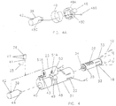
- FIG. 2 the key 10 is shown inserted into lock barrel 31 which is fitted into mating aperture 19 of lock body 20 having lock tongue 21.
- the barrel 31 has contact portals 22 and also has upper component 23 which fits into mating recess 24.
- the barrel 31 is also provided with wires 25.
- the lock body 20 is of mechanical nature having a custom wire bus (not shown).
- the lock body 20 incorporates a slider bar 21A having slot 21 B for engagement with trigger latch 48 shown in FIG. 4A.
- FIGS. 3A and 3C the key 10 is shown having components in the form of the sensor 14, insulator insert 27 and circuit board 28 which fits into recess 29 of insulator insert 27.
- Insulator insert 27 is slidably attached to key body 13 and bonded thereto.
- the circuit board 28 is shown on both sides as is key body 13, which is formed from sensor 14, insulator insert 27 and circuit board 28 as illustrated.
- Sensor 14 fits within recess 30 of insulator 27 and, more specifically, is retained by retaining flange 30A of recess 30.
- the circuit board 28 has wire leads or contact traces 28A which bond or solder to corresponding tabs 26 on sensor 14.
- Circuit board 28 also has at the end adjacent wire leads 28A sloping side edges 28B, which engage with corresponding edges 28C of recess 29.
- the key body 13 as shown in FIG. 3A and 3C also includes body plates or flanges 13A and 13B separated by a slot 13C of complementary shape to insulator insert 27 which receives insulator insert 27 as shown in FIG. 3A.
- FIG. 4 the key 10 is shown fitted into a lock cylinder 18 having contact portals 32.
- the cylinder 18 has flange 33 and end 34 having a slot 35.
- the cylinder 18 also has tumblers 36.
- Contact portals 32 touch mating contact portals 22, when cylinder 18 is inserted into lock barrel 31.
- the contact portals 22 transmit electronic signals with an external processor as hereinafter described through lock body 20.
- the contact portals 22 exchange electronic signals with an processing unit in lock body 20 which has an electronic interface with an external processor, such as a host computer, as described hereinafter.
- the electronic interface with the outside processor may be of any suitable type, such as USB, parallel, serial or IEEE1384 firewire signals. This does not preclude conforming to IEEE 802.15 Wireless Personal Area Network (WPAN) including Bluetooth, HomeRF, HighRate RF and wide spectrum RF.
- WPAN Wireless Personal Area Network
- the processing unit may also provide return electrical signals that control a linear motor or solenoid 38 which releases a cylindrical locking pin 39 which fits within bore 40 of cylinder 18.
- Motor 38 has a spring loaded piston 41, which engages with aperture 42 of locking pin 39.
- Motor 38 also fits within mating socket 43 of barrel 31.
- Locking pin 39 has projection 44, which engages with slot 35 of cylinder 18.
- Motor 38 also has contacts 47, which engage with wires 25.
- trigger latch 48 of barrel 31 shown in the locked position and which is located on rotatable gear 48A shown in FIG. 4A which has a protective sheath 49. The trigger latch 48 engages with slot 50 in an unlocked position providing for maintenance of barrel 31.
- piston 41 retracts within motor 38 thereby allowing locking pin 39 to rotate.
- a small pin 48B which interconnects locking pin 39 and gear wheel 48A as shown in FIG. 4A wherein pin 48B engages in hole 48C of locking pin 39 and also engages in a selected recess 48D of gear wheel 48A.
- Latch 48 moves downwardly from the position shown in FIG. 4 to unlock tongue or latch plate 21 by engagement with slot 21B shown in FIG. 2.
- the upper component 23 of barrel 31 has screw threaded attachment holes 51A which facilitate attachment to lock body 20.
- lock 20 may incorporate a suitable processing unit (not shown) which includes suitable software and a database to match and validate biometric data in the form of a biocode provided by an electrical signal from sensor 14.
- the processing unit may also interface with a host computer, through which biocodes may be enrolled as described hereinafter. Wires 25 may be connected to the processing unit or to the host computer.
- the lock 20 body controls access in two different ways i.e. requiring a valid return signal from the processing unit to unlock the locking pin 39 as well as mechanical tumblers 36 adding further security.
- FIG. 5 shows key 10 inserted into keyway or slot 31A of cylinder 18 and FIG. 6 is taken along line A-A of FIG. 5.
- FIG. 6 there is shown individual insulators or insulator sleeves 50A and 51, which contact pins 52 and 53.
- FIG. 6A shows insulators 50A and 51 engaging in a press fit within key body 13 and contact pins 52 and 53 engaging within a press fit within mating insulators 50A and 51.
- Contact pins 52 and 53 each have a barbed point 52A, which drive into a solder puddle on circuit board 28. Insulators 50A and 51 are aligned normally to a longitudinal axis of key body 13.
- FIG. 7 is taken along line B-B of FIG. 5.
- contact pin 55 which is a sliding fit within insulator 54
- fuzz button 57 The purpose of fuzz button 57 is to provide electrical continuity between contact pins 55 and 56 under the influence of its own spring pressure.
- Insulators 57. are shown aligned normally to the longitudinal axis of the key body 13. A closer detail of this arrangement is shown in FIG. 8. An exploded view is also shown in FIG. 8A.
- FIG. 9 is a section along line C-C of FIG. 4, a detailed view of the contact detail shown in FIG. 10, shows insulator 63 which is bonded within barrel 31, contact pin 62 adapted for press fit within insulator 63, fuzz button 64 and additional contact pin 65 which has a sliding fit within insulator 63.
- An exploded view is shown in FIG. 10A.
- the processing unit may be operated in either a stand alone environment (platform independent) i.e. as described above or aided with a remote host computer connected by any suitable means including serial, parallel, or USB connection or IEEE 802.15 WPAN RF technology.
- the processing unit may comprise a Digital Signal Process (DSP) unit or ASIC processor.
- DSP Digital Signal Process
- the processing unit captures and extracts a biocode of the fingerprint scanned by the biometric key.
- the biocode is a fingerprint map or digital signature that permits identity verification of a person.
- the extraction and matching algorithm is based upon minutiae comparison.
- the maximum size of a biocode in this particular context may be 254 bytes.
- the processing unit can manage up to 2048 biocodes in its own database or a remote host computer may manage the database if more biocodes are needed. In order to take full advantage of the features available, such as administrative reports and user queries, a remote computer may interface to the processing unit.
- the processing unit may be a self-contained board using only an external power source, an interface to the biometric sensor, and a connection to the host computer.
- the processing unit may also contain on- board RAM, ROM, communications interface, fingerprint recognition software and database manager, all integrated into an optimised device. It is the task of the system integrator to fulfil the relevant specifications for the entire system operation.
- the processing unit may also enrol biocodes directly to the point of origin via the key. Users are grouped into two categories: administrator and regular users. The administrator registers, checks and deletes the authorised people in tne database.
- FIG. 11 there is shown an alternative embodiment of the invention, wherein key 10 is fitted within a stationary receptor body 18A and electrical continuity is provided by FIGS. 12 and 13, which represent sections along lines A-A and D-D of FIG. 11 and which relevant contact detail is shown in a similar manner as shown in FIGS. 6 and FIG. 8.
- FIG. 12 there is shown contact pins 52 and 53 which are bounded by insulators 50A and 51 as described previously.
- Contact pins 52 and 53 touch mating contacts 56 of receptor body 18A, which touch fuzz button 57.
- Wiring 66 is attached to fuzz button 57 by solder 67 as shown in FIG. 14.
- Key 10 is inserted in slot 68 of receptor body 18A as shown in FIG. 16.
- Wiring 66 is routed in wire access grooves 69, which are shown in FIGS. 13 and 17.
- Receptor body 18A is also provided with a light emitting diode 70, shown in i FIG. 16, which is a visual signal for acceptance (i.e. green) or rejection of the signal (i.e. red).
- Wiring 66 has soldered points 66A, 66B, 66C and 67D as shown in FIG. 17.
- Receptor body 18A may be mounted inside a drawer, box, housing of any security system whereby receptor body 18A may be wired to the processing unit (not shown) in the security system which requires access by biometric key 10.
- processing unit not shown
- biometric key 10 a mechanical or electromechanical lock body 20 as shown in the embodiment of FIGS. 1-10.
- the sensor 14 may be obtained commercially from Siemens and is sold under the Registered Trade Mark FingerTip. It is sold as part of a module, which also includes a processing unit connected to the FingerTip sensor chip by a conductor and the module is marketed by Siemens under the Trade Mark TopSec 10 - Module A1.0.
- the module reads out of the FingerTip sensor the biometric data, evaluates it and compares it to a database contained in the memory of the module. It is emphasised that it is only the sensor component that is utilised in the present invention and which is incorporated in key body 13 as described herein.
- processing unit from the module is an example of a suitable processing unit utilised in the present invention.
- the key 10 may also include a smart card chip 14A (not shown) shown on the same side as sensor 14 or on the opposite or obverse side.
- the invention may include within its scope the abovementioned receptor body in the form of lock cylinder 18 or stationary body 18A.
- the invention may also include the barrel 31 per se.
- the smart card chip 14A may comprise an integrated circuit with ISO 7816 interface and/or a processor integrated circuit and/or a personal identity token containing IC-S.
- FIG. 18 there is shown a block diagram representing the chain of events upon use of the biometric key of the invention wherein the following events take place, i.e.
- FIG. 19 there is shown a schematic diagram how enrolment of biometric data signature may be accomplished via a host computer whereby:
- biometric key of the invention is versatile in operation, has relatively simple structure and provides a high degree of security.
- the key body may have inbuilt processor chip or processing unit instead of the processing unit being incorporated in the receptor body.
Abstract
Description
- THIS INVENTION relates to a biometric key and more particularly relates to a biometric key having a key body which contains a biometric sensor capable of capturing a key holder's biometric data and transmitting the data through the biometric sensor to a processor in order to validate authorised use of the key through biometric verification.
- Currently keys are used for a wide variety of applications that comprise a mechanical or electromechanical cipher, which carries coded information. One example of the latter is keys described in European Patent 472495 which has a specific mechanism located on opposed edges of the key which co-operates with a corresponding mechanism built into a mating lock cylinder before a locking system incorporating the lock cylinder may be opened.
- While such keys are simple to use, it will be appreciated that the level of security is not high because there are no means currently available for verifying that the person using the key is an authorised user. This means that while a conventional mechanical or electromechanical lock operated by a key presents physical access to a building such a key may be readily copied or it may be lost or given to other persons who may then gain access to the building on an unauthorised basis. Thus, physical access to the building is provided by those in control of the key.
- Conventional biometric control systems are well known and refer to encoding of a person's specific biometric features into a memory of the biometric control apparatus with an external process (e.g. storage memory, matching algorithm and return signal). A coded version of an authorised biometric feature can be stored. When verification is required, it is necessary for the user to present his biometric characteristic feature to the biometric control apparatus, which then compares the biometric characteristic feature with the authorised biometric feature. If a match occurs, then the biometric control system permits access to a facility controlled by the biometric control system.
- Biometrically secured control systems for preventing unauthorised use of vehicles are described in US Patent 5867802. This reference describes a method and system for restricting use of a vehicle to person(s) whose fingerprints match biometric data stored within a memory in the control system of the vehicle. A user's digitised fingerprints are stored in a ROM in the BIOS of a microcontroller or in a ROM accessed by a microcontroller. The microprocessor's primary task is that of executing instructions, which are related to the operation of the vehicle such as regulation of the fuel flow rate, and other tasks. Before the microprocessor can execute its instructions related to the primary task, it must complete and exit a conditional loop of instructions that relate to validating the user's "real input" biometric data. Real scanned fingerprints must be compared with fingerprints(s) stored in ROM. If the result of the comparison is a match, then the operating loop is satisfied and the microprocessor can execute its instructions relating to operation of the vehicle. In US Patent 5607802 use is made of a conventional fingerprint scanning device and related circuitry coupled to the microprocessor. A key operated ignition switch is coupled to the microprocessor to provide a signal for providing power to the microprocessor before it may control operations related to the vehicle.
- Another example of biometrically secured control systems is described in US Patent 5915936 which refers to a firearm which incorporates a pressure sensor for sensing grasping of a butt section of the firearm by a palm of the user as well as a scanning sensor for scanning a palm print of the user and generating a data signal representative of the scanned palm print after actuation of the pressure sensor. The firearm can only be used by authorised users wherein a memory unit stores data signals representative of the authorised users.
- US Patent 5987155 refers to a biometric information input device having an integral smart card reader. The device provides co-operative operation of the smart card and the input device to provide user specific processing of biometric information provided by the user. Examples of biometric input devices referred to in this reference are those incorporating a microphone or those which comprise a contact imaging device such as a fingerprint scanner.
- The abovementioned prior art references are illustrative of biometric control systems which can only be operated upon use of a vehicle ignition key as described in US Patent 5867802, a pressure sensor in the case of US Patent 5915936 or a smart card in the case of US Patent 5987155. It therefore will be appreciated that such conventional biometric control systems are non-versatile in being restricted to a specific application, and also require the use of additional structure relative to the specific application. Thus for example the biometric input device of US 5987155 requires as an essential component a card slot for acceptance of the smart card.
- It is an object of the present invention to provide a biometric key, which may reduce the disadvantages of the prior art, discussed above.
- The invention provides a biometric key, having a key body incorporating a biometric sensor for transmission of a signal representing a biocode of data generated by the biometric sensor, said key body in use engageable with a receptor body for interaction with the key body to forward the signal to processing means for granting access to an authorised user to a facility accessible by the biometric key.
- The interaction between the key body and the receptor body may, for forwarding of the signal to the processing means, involve the use of electrical contacts, wherein the key body has one or more contacts as hereinafter described with touch mating contact(s) of the receptor body. However, such interaction may also involve a transmitter of the key interacting with a receiver of the receptor body and such interaction may be of an optical, infra-red, radio-frequency or fibre-optic nature.
- The key body may be similar to a conventional key which unlocks mechanical locks wherein the key has a blade with a plurality of wards that co-operate with lock tumblers in a conventional manner to unlock the mechanical lock as hereinafter described. The key body may also have a handle or gripping part; which may have the biometric sensor, applied or attached thereto or embedded therein. Preferably the sensor is accommodated within a mating recess of the key body and is provided with contacts or pins forming one example of the contact means which may engage with a circuit board also accommodated within the key body.
Preferably the sensor is surrounded by an insulator insert. - Alternatively the key body may omit wards and have a blade or end portion, which engages with a mating slot in the receptor body discussed above. In this embodiment the receptor body may interface with the processing means, whereby upon recognition of an authorised signal by the processing means, access to the facility may be provided.
- The sensor may be a solid state sensor manufactured by Pollex or Siemens and the sensor may scan an appropriate biometric characteristic of the key holder. Alternatively the sensor may be manufactured by Thompson, Veridicon or Harris, which are all well known solid state manufacturers. The scanning sensor may be carried out using a number of techniques which may include capacitance, resistance, thermal imagery, structure geometry, bone structure or vein structure. Suitably the scanning sensor scans a fingerprint or thumb print.
- The key body may also have embedded therein a smart card chip such as a wired logic chip also known as an "intelligent memory" chip, which has inbuilt logic. Embedded processor chips, added to the key body, may contain memory and local processor capabilities. The embedded processor chip, embedded within the key body, may be used to encrypt/decrypt data, which makes this type of biometric key a unique person identification key.
- Examples of use of the biometric key of the invention may be as an ignition key of a vehicle, a key to a storage facility such as a drawer or lid of a box, a security facility such as a security door or security window, to operate an elevator or lift or to initiate actuation of an electric motor, hydraulic motor, engine or other form of drive means or even hydraulic or pneumatically actuated ram assemblies. Each of the foregoing are examples of facilities which may be accessible by the biometric key of the invention.
- It therefore will be appreciated from the foregoing that the biometric key of the invention is extremely versatile having many applications or uses and also extremely simple in structure to at least partially overcome the disadvantages of conventional biometric control systems as described above. The biometric key of the invention also involves a high degree of security to overcome the problems of conventional keys as described above.
- The invention also includes within its scope a receptor body engageable with a biometric key, said biometric key having a key body incorporating a biometric sensor for transmission of a signal representing a biocode of data generated by the biometric sensor, wherein said receptor body interacts with the key body to forward the signal to processing means for granting access to an authorised user to a facility accessible by the biometric key.
- It will be appreciated from the illustrated embodiments hereinafter that the receptor body may comprise a lock component such as a lock cylinder as shown in FIGS. 1-10A or a stationary body forming part of a drawer or door as shown in FIGS. 11-19.
- The invention also provides a security system for use with a facility to prevent unauthorised access to the facility which includes the biometric key as described above as well as the receptor body as described above.
- The invention also relates to a method for providing access to a facility, which includes the steps of:
- (i) inserting a key having a biometric sensor into a receptor body whereby upon engagement of the key with the receptor body a signal representing a biocode of data generated by the biometric sensor is forwarded to processing means;
- (ii) matching the biocode with a database associated with the processing means to permit validation of the biocode; and
- (iii) providing access to a facility, which incorporates the receptor body, to an authorised person, when said validation has taken place.
-
- Reference may now be made to a preferred embodiment of the present invention as described in the accompanying drawings wherein:
- FIG. 1 is a view of the biometric key of the invention held in a person's hand;
- FIG. 2 is a perspective view of a biometric key of the invention, which is inserted into a corresponding lock barrel of a lock body;
- FIG. 3A is an exploded perspective view of the key of FIG. 1 showing all parts thereof;
- FIG. 3B is a perspective view of the circuit board shown in FIG. 1 from an opposite side;
- FIG. 3C is a perspective view of the key shown in FIG. 3A from an opposite side;
- FIG. 4 is an exploded perspective view of components of a lock body comprising a lock cylinder and associated barrel;
- FIG. 4A is an exploded perspective view of components of the lock body shown in FIG. 4;
- FIG. 5 is a plan view of the biometric key of the invention shown in FIG. 1 inserted in the lock cylinder;
- FIG. 6 is a section through line A-A of FIG. 5;
- FIG. 6A is an exploded view of the components of FIG. 6;
- FIG. 7 is a section through line B-B of FIG. 5;
- FIG. 8 is a detailed view of contact detail shown in FIG. 7;
- FIG. 8A is an exploded view of the components of FIG. 8;
- FIG. 9 is a section through line C-C of FIG. 4;
- FIG. 10 is a detailed view of contact detail shown in FIG. 9;
- FIG. 10A is an exploded view of the components of FIG. 10;
- FIG. 11 is a plan view of a biometric key of the invention inserted into a stationary receptor body in another embodiment of the invention;
- FIG. 12 is a section through line A-A of FIG. 11;
- FIG. 13 is a section through line D-D of FIG. 11;
- FIG. 14 is a detailed view of a contact shown in FIG. 13;
- FIG. 15 is an exploded perspective view of the key of FIG. 11 separated from the receptor body;
- FIG. 16 is a perspective view of the receptor body barrel of FIG. 15 from another orientation:
- FIG. 17 is a detailed view of a contact shown in FIG. 15;
- FIG. 18 is a block diagram describing the chain of events upon operation of the biometric key of the invention; and
- FIG. 19 is a schematic view showing enrolment of biometric data signature via an external host computer.
-
- In FIG. 1 there is provided a
biometric key 10 of the invention held in thehand 11 havingcontrol portals 12. The key 10 has akey body 13 and asensor 14 being contacted bythumb 15. The key 10 is also provided withblade 16 having wards 17. - In FIG. 2 the key 10 is shown inserted into
lock barrel 31 which is fitted intomating aperture 19 oflock body 20 havinglock tongue 21. Thebarrel 31 hascontact portals 22 and also hasupper component 23 which fits intomating recess 24. Thebarrel 31 is also provided withwires 25. Thelock body 20 is of mechanical nature having a custom wire bus (not shown). - The
lock body 20 incorporates aslider bar 21A having slot 21 B for engagement withtrigger latch 48 shown in FIG. 4A. - In FIGS. 3A and 3C the key 10 is shown having components in the form of the
sensor 14,insulator insert 27 andcircuit board 28 which fits intorecess 29 ofinsulator insert 27. Insulator insert 27 is slidably attached tokey body 13 and bonded thereto. Thecircuit board 28 is shown on both sides as iskey body 13, which is formed fromsensor 14,insulator insert 27 andcircuit board 28 as illustrated.Sensor 14 fits withinrecess 30 ofinsulator 27 and, more specifically, is retained by retainingflange 30A ofrecess 30. Thecircuit board 28 has wire leads or contact traces 28A which bond or solder to correspondingtabs 26 onsensor 14.Circuit board 28 also has at the end adjacent wire leads 28A sloping side edges 28B, which engage withcorresponding edges 28C ofrecess 29. - The
key body 13 as shown in FIG. 3A and 3C also includes body plates orflanges 13A and 13B separated by aslot 13C of complementary shape to insulator insert 27 which receivesinsulator insert 27 as shown in FIG. 3A. - In FIG. 4 the key 10 is shown fitted into a
lock cylinder 18 havingcontact portals 32. Thecylinder 18 hasflange 33 and end 34 having aslot 35. Thecylinder 18 also hastumblers 36. -
Contact portals 32 touchmating contact portals 22, whencylinder 18 is inserted intolock barrel 31. Thecontact portals 22 transmit electronic signals with an external processor as hereinafter described throughlock body 20. Alternatively, and more preferably, thecontact portals 22 exchange electronic signals with an processing unit inlock body 20 which has an electronic interface with an external processor, such as a host computer, as described hereinafter. The electronic interface with the outside processor may be of any suitable type, such as USB, parallel, serial or IEEE1384 firewire signals. This does not preclude conforming to IEEE 802.15 Wireless Personal Area Network (WPAN) including Bluetooth, HomeRF, HighRate RF and wide spectrum RF. The processing unit may also provide return electrical signals that control a linear motor orsolenoid 38 which releases acylindrical locking pin 39 which fits within bore 40 ofcylinder 18.Motor 38 has a spring loadedpiston 41, which engages withaperture 42 of lockingpin 39.Motor 38 also fits withinmating socket 43 ofbarrel 31. Lockingpin 39 hasprojection 44, which engages withslot 35 ofcylinder 18.Motor 38 also hascontacts 47, which engage withwires 25. There is also providedtrigger latch 48 ofbarrel 31, shown in the locked position and which is located onrotatable gear 48A shown in FIG. 4A which has aprotective sheath 49. Thetrigger latch 48 engages withslot 50 in an unlocked position providing for maintenance ofbarrel 31. When unlocking oflock body 20 is initiated,piston 41 retracts withinmotor 38 thereby allowing lockingpin 39 to rotate. There is provided a small pin 48B which interconnects lockingpin 39 andgear wheel 48A as shown in FIG. 4A wherein pin 48B engages inhole 48C of lockingpin 39 and also engages in a selected recess 48D ofgear wheel 48A.Latch 48 moves downwardly from the position shown in FIG. 4 to unlock tongue or latchplate 21 by engagement with slot 21B shown in FIG. 2. Theupper component 23 ofbarrel 31 has screw threadedattachment holes 51A which facilitate attachment to lockbody 20. It will also be appreciated that as referred toabove lock 20 may incorporate a suitable processing unit (not shown) which includes suitable software and a database to match and validate biometric data in the form of a biocode provided by an electrical signal fromsensor 14. The processing unit may also interface with a host computer, through which biocodes may be enrolled as described hereinafter.Wires 25 may be connected to the processing unit or to the host computer. Thelock 20 body controls access in two different ways i.e. requiring a valid return signal from the processing unit to unlock the lockingpin 39 as well asmechanical tumblers 36 adding further security. - FIG. 5 shows key 10 inserted into keyway or
slot 31A ofcylinder 18 and FIG. 6 is taken along line A-A of FIG. 5. In FIG. 6 there is shown individual insulators orinsulator sleeves insulators key body 13 and contact pins 52 and 53 engaging within a press fit withinmating insulators barbed point 52A, which drive into a solder puddle oncircuit board 28.Insulators key body 13. - FIG. 7 is taken along line B-B of FIG. 5. There is shown
contact pin 55, which is a sliding fit withininsulator 54, andfuzz button 57. The purpose offuzz button 57 is to provide electrical continuity between contact pins 55 and 56 under the influence of its own spring pressure.Insulators 57. are shown aligned normally to the longitudinal axis of thekey body 13. A closer detail of this arrangement is shown in FIG. 8. An exploded view is also shown in FIG. 8A. - FIG. 9 is a section along line C-C of FIG. 4, a detailed view of the contact detail shown in FIG. 10, shows
insulator 63 which is bonded withinbarrel 31,contact pin 62 adapted for press fit withininsulator 63,fuzz button 64 andadditional contact pin 65 which has a sliding fit withininsulator 63. An exploded view is shown in FIG. 10A. - The processing unit may be operated in either a stand alone environment (platform independent) i.e. as described above or aided with a remote host computer connected by any suitable means including serial, parallel, or USB connection or IEEE 802.15 WPAN RF technology. The processing unit may comprise a Digital Signal Process (DSP) unit or ASIC processor. The processing unit captures and extracts a biocode of the fingerprint scanned by the biometric key. The biocode is a fingerprint map or digital signature that permits identity verification of a person. The extraction and matching algorithm is based upon minutiae comparison. The maximum size of a biocode in this particular context may be 254 bytes. The processing unit can manage up to 2048 biocodes in its own database or a remote host computer may manage the database if more biocodes are needed. In order to take full advantage of the features available, such as administrative reports and user queries, a remote computer may interface to the processing unit.
- The processing unit may be a self-contained board using only an external power source, an interface to the biometric sensor, and a connection to the host computer. The processing unit may also contain on- board RAM, ROM, communications interface, fingerprint recognition software and database manager, all integrated into an optimised device. It is the task of the system integrator to fulfil the relevant specifications for the entire system operation.
- There is a variety of enrolment means to enter a biocode into the processor database. The most common is the remote host computer via a suitable connection. A Smartcard Reader may also be used in conjunction with a 10-key pad to control the processing unit. There is a multitude of ways to initiate administrator functions in a stand alone environment.
- The processing unit may also enrol biocodes directly to the point of origin via the key. Users are grouped into two categories: administrator and regular users. The administrator registers, checks and deletes the authorised people in tne database.
- In FIG. 11, there is shown an alternative embodiment of the invention, wherein key 10 is fitted within a
stationary receptor body 18A and electrical continuity is provided by FIGS. 12 and 13, which represent sections along lines A-A and D-D of FIG. 11 and which relevant contact detail is shown in a similar manner as shown in FIGS. 6 and FIG. 8. In FIG. 12 there is shown contact pins 52 and 53 which are bounded byinsulators touch mating contacts 56 ofreceptor body 18A, which touchfuzz button 57.Wiring 66 is attached tofuzz button 57 by solder 67 as shown in FIG. 14.Key 10 is inserted inslot 68 ofreceptor body 18A as shown in FIG. 16.Wiring 66 is routed inwire access grooves 69, which are shown in FIGS. 13 and 17.Receptor body 18A is also provided with alight emitting diode 70, shown in i FIG. 16, which is a visual signal for acceptance (i.e. green) or rejection of the signal (i.e. red).Wiring 66 has solderedpoints -
Receptor body 18A may be mounted inside a drawer, box, housing of any security system wherebyreceptor body 18A may be wired to the processing unit (not shown) in the security system which requires access bybiometric key 10. Thus in this embodiment there is no requirement of a mechanical orelectromechanical lock body 20 as shown in the embodiment of FIGS. 1-10. - The
sensor 14 may be obtained commercially from Siemens and is sold under the Registered Trade Mark FingerTip. It is sold as part of a module, which also includes a processing unit connected to the FingerTip sensor chip by a conductor and the module is marketed by Siemens under the Trade Mark TopSec 10 - Module A1.0. The module reads out of the FingerTip sensor the biometric data, evaluates it and compares it to a database contained in the memory of the module. It is emphasised that it is only the sensor component that is utilised in the present invention and which is incorporated inkey body 13 as described herein. - However, the processing unit from the module is an example of a suitable processing unit utilised in the present invention.
- The key 10 may also include a smart card chip 14A (not shown) shown on the same side as
sensor 14 or on the opposite or obverse side. - It will also be appreciated that the invention may include within its scope the abovementioned receptor body in the form of
lock cylinder 18 orstationary body 18A. The invention may also include thebarrel 31 per se. - The smart card chip 14A may comprise an integrated circuit with ISO 7816 interface and/or a processor integrated circuit and/or a personal identity token containing IC-S.
- In FIG. 18 there is shown a block diagram representing the chain of events upon use of the biometric key of the invention wherein the following events take place, i.e.
- (i) the key 10 or 10A is inserted into
lock cylinder 18 orstationary receptor body 18A; - (ii) the key contacts make connection with the receptor body contacts;
- (iii) power is provided to the
sensor 14 in the key 10, via thereceptor body - (iv) a biometric is read through the
sensor 14, and that data is passed through the key contacts and sent to the processing unit; - (v) the processing unit extracts biometric data signature, and compares to previously stored biometric data signature for match;
- (vi) if a match exists, the external signal latches or unlatches (i.e. open/closed); and
- (vii) the key 10 is removed from the receptor body.
-
- In FIG. 19 there is shown a schematic diagram how enrolment of biometric data signature may be accomplished via a host computer whereby:
- (a) the host computer software requests personal and/or demographic information relative to the authorised user;
- (b) the biometric data signature is captured from the sensor through the key, via the receptor body interfaced to the host computer;
- (c) personal and/or demographic information is stored with biometric data signature and stored within database of the host computer;
- (d) a search is performed against the database for previous enrolments (i.e. prevents multiple enrolments under assumed names);
- (e) if not found, authorised user is enrolled into database;
- (f) if found, enrolment is denied; and
- (g) database located on the processing unit and host computer database is updated to reflect new enrolment.
-
- It will be appreciated from the foregoing that the biometric key of the invention is versatile in operation, has relatively simple structure and provides a high degree of security.
- In a variation of the foregoing it will be appreciated that the key body may have inbuilt processor chip or processing unit instead of the processing unit being incorporated in the receptor body.
Claims (39)
- A biometric key having a key body incorporating a biometric sensor for transmission of a signal representing a biocode of data generated by the biometric sensor, said key body in use engageable with a receptor body for interaction with the key body to forward the signal to processing means for granting access to an authorised user to a facility accessible by the biometric key.
- A biometric key as claimed in claim 1, wherein the key body has one or more electrical contact(s) which, in use, touch mating contact(s), of the receptor body.
- A biometric key as claimed in claim 1, wherein the sensor is surrounded by an insulator in the key body.
- A biometric key as claimed in claim 3, wherein the insulator is insertable into a slot of the key body and attached thereto.
- A biometric key as claimed in claim 3, wherein the insulator is slidably attached to the key body and bonded thereto.
- A biometric key as claimed in claim 3, 4 or 5, wherein the biometric sensor is accommodated within a mating recess in the insulator.
- A biometric key as claimed in any one of claims 2-6, wherein the key body incorporates a circuit board engaging with said one or more contacts.
- A biometric key as claimed in claim 3, wherein key body incorporates a circuit board engaging with said one or more contacts, said circuit board being accommodated within a cavity of the insulator adjacent the biometric key.
- A biometric key as claimed in claim 8, wherein the circuit board at one end has contact traces or wire leads which engage with corresponding contact traces of an adjacent end of the biometric sensor.
- A biometric key as claimed in claim 9, wherein the insulator incorporates a plurality of contact portals in contact with corresponding contacts or wire leads of the circuit board.
- A biometric key as claimed in any one of claims 2-10, wherein the or each contact is at least partly surrounded by an insulator sleeve.
- A biometric key as claimed in claim 11, wherein the, or each insulator sleeve is aligned normally to a longitudinal axis of the key body.
- A biometric key as claimed in any preceding claim, wherein the key body has a handle or gripping part incorporating the biometric sensor and a blade portion.
- A biometric key as claimed in claim 13, wherein the blade portion has a plurality of wards.
- A biometric key as claimed in any one of claims 1-13, wherein the blade portion is plate like in shape not incorporating wards, for insertion into a slot of the receptor body.
- A biometric key as claimed in claim 11 or 12, wherein each contact comprises a pair of contact pins located in accommodating insulator sleeves, wherein each contact pin is separated by the circuit board.
- A biometric key as claimed in any preceding claim, wherein the key body incorporates a smart chip.
- A biometric key as claimed in claim 1, wherein the key body has a transmitter for interaction with a receiver of the receptor body for transmission of the signal.
- A biometric key substantially has herein described with reference to the accompanying drawings.
- A receptor body engageable with a biometric key, said biometric key having a key body incorporating a biometric sensor for transmission of a signal representing a biocode of data generated by the biometric sensor, wherein said receptor body interacts with the key body to forward the signal to processing means for granting access to an authorised user to a facility accessible by the biometric key.
- A receptor body as claimed in claim 20, wherein the receptor body has one or more electrical contacts, which in use, touch mating contact(s) of the biometric key for forwarding of the signal to the processing means.
- A reader as claimed in claim 21, wherein the receptor body is a mechanical lock body engageable with the biometric key, which key has a blade portion with a plurality of wards which engage with corresponding tumblers in the lock body.
- A receptor body as claimed in claim 22, wherein the lock body includes a barrel having said tumblers and also a plurality of contacts as well as a lock cylinder for engagement with the barrel, which lock cylinder has a plurality of contact portals for touching corresponding contacts of the barrel.
- A receptor body as claimed in any one of claims 20-23, which incorporates an internal processing unit, which corresponds to said processing means.
- A receptor body as claimed in claim 24, wherein the internal processing unit has an interface with an external processor or computer for enrolment of biometric data.
- A receptor body as claimed in claim 22, wherein after analysis of the signal by the processing means, access to the facility is provided by activation of a linear motor or solenoid of a lock cylinder located within the lock body, which is in electrical connection with the processing means, wherein said linear motor or solenoid is actuated to rotate a locking pin within the lock body to facilitate unlocking of the lock body.
- A receptor body as claimed in claim 26, wherein the rotation of the locking pin causes corresponding rotation of a barrel engageable with the lock cylinder.
- A receptor body as claimed in claim 20, 21, 24 or 25, which has a slot engageable with a blade portion of the biometric key, wherein said blade portion does not incorporate wards.
- A receptor body as claimed in any one of claims 20-28, wherein each of the contacts contained therein are spring biased to a position in abutment with a corresponding contact pin of the biometric key body.
- A receptor body as claimed in claim 29, wherein each of the contacts contained therein are normal to a longitudinal axis of the biometric key in use
- A receptor body as claimed in claim 29, wherein each of the contacts are accommodated within an insulator.
- A receptor body as claimed in claim 31, wherein within each insulator there are provided an inner contact for touching corresponding contacts of the biometric key in use and an outer contact separated from an adjacent inner contact by a spring.
- A receptor body as claimed in any one of claims 20-32, wherein there is incorporated an indicator means indicating validation or rejection of biometric data generated by the sensor.
- A receptor body as claimed in claim 31, wherein the indicator means is a light emitting diode.
- A receptor body as claimed in claim 26, which incorporates a receiver for interaction with a transmitter of the key body for transmission of the signal.
- A security system for use. with a facility to prevent unauthorised access to the facility, which includes:(a) a biometric key having a key body incorporating a biometric sensor for transmission of a signal representing a biocode of data generated by the biometric sensor; and(b) a receptor body engageable with the biometric key, wherein said receptor body upon engagement with the key body interacts with the key body to forward the signal to processing means associated with the receptor body for granting access to the facility to an authorised user.
- A security system as claimed in claim 36, wherein the key body has one or more electrical contacts, which touch mating contact(s), when forwarding said signal.
- A method for providing access to a facility which includes the steps of:(i) inserting a key having a biometric sensor into a receptor body, whereby upon engagement of the key with the receptor body a signal representing a biocode of data generated by the biometric sensor is forwarded to processing means;(ii) matching the biocode with a database associated with the processing means to permit validation of the biocode; and(iii) providing access to a facility, which incorporates the receptor body to an authorised user, when said validation has taken place.
- A method as claimed in claim 38, wherein the processing means is interfaced with an external computer, which accepts enrolments to said database.
Applications Claiming Priority (2)
| Application Number | Priority Date | Filing Date | Title |
|---|---|---|---|
| AU7164400 | 2000-05-16 | ||
| AU71644/00A AU757159C (en) | 2000-05-16 | 2000-11-16 | Biometric key |
Publications (3)
| Publication Number | Publication Date |
|---|---|
| EP1157906A2 true EP1157906A2 (en) | 2001-11-28 |
| EP1157906A3 EP1157906A3 (en) | 2001-12-05 |
| EP1157906B1 EP1157906B1 (en) | 2005-07-13 |
Family
ID=3754477
Family Applications (1)
| Application Number | Title | Priority Date | Filing Date |
|---|---|---|---|
| EP20010201081 Expired - Lifetime EP1157906B1 (en) | 2000-05-16 | 2001-03-23 | Biometric key |
Country Status (5)
| Country | Link |
|---|---|
| US (1) | US7218202B2 (en) |
| EP (1) | EP1157906B1 (en) |
| AT (1) | ATE299451T1 (en) |
| DE (1) | DE60111892T2 (en) |
| ES (1) | ES2245665T3 (en) |
Cited By (7)
| Publication number | Priority date | Publication date | Assignee | Title |
|---|---|---|---|---|
| EP1647942A2 (en) * | 2004-10-13 | 2006-04-19 | Mua Hua Investments Ltd. | Biometric security assembly |
| WO2006132576A1 (en) * | 2005-06-10 | 2006-12-14 | Assa Ab | A lock key and a method of its manufacture |
| WO2007144766A2 (en) * | 2006-06-14 | 2007-12-21 | Gironi System S.R.L. | Electronic locking/unlocking apparatus |
| US9607189B2 (en) | 2015-01-14 | 2017-03-28 | Tactilis Sdn Bhd | Smart card system comprising a card and a carrier |
| US10037528B2 (en) | 2015-01-14 | 2018-07-31 | Tactilis Sdn Bhd | Biometric device utilizing finger sequence for authentication |
| WO2019077354A1 (en) * | 2017-10-17 | 2019-04-25 | Vam System Limited | Electromechanic protection device for the motor vehicles, mainly for interruption of the electric and/or electronic circuits |
| US10395227B2 (en) | 2015-01-14 | 2019-08-27 | Tactilis Pte. Limited | System and method for reconciling electronic transaction records for enhanced security |
Families Citing this family (31)
| Publication number | Priority date | Publication date | Assignee | Title |
|---|---|---|---|---|
| US7958359B2 (en) * | 2001-04-30 | 2011-06-07 | Digimarc Corporation | Access control systems |
| US20030061364A1 (en) * | 2001-09-26 | 2003-03-27 | International Business Machines Corporation | Method and system in electronic commerce for providing a secure wireless connection service for mobile personal area networks |
| US6696970B2 (en) * | 2001-12-20 | 2004-02-24 | Xerox Corporation | Retractable pin array identification apparatus and method |
| US20040232228A1 (en) * | 2003-05-20 | 2004-11-25 | Gotfried Bradley L. | Monitoring system |
| US6888445B2 (en) * | 2003-05-20 | 2005-05-03 | Bradley L. Gotfried | Vehicle identification system |
| US6923370B2 (en) * | 2003-05-20 | 2005-08-02 | Bradley L. Gotfried | Access system |
| US20050044909A1 (en) * | 2003-08-28 | 2005-03-03 | Volker Lange | Knob cylinder with biometrical sensor |
| JP4603350B2 (en) * | 2004-12-24 | 2010-12-22 | 富士通株式会社 | Personal authentication device |
| WO2006119127A2 (en) * | 2005-05-03 | 2006-11-09 | Pocrass Alan L | Electronic lock system and method of use thereof |
| US20070171027A1 (en) * | 2006-01-25 | 2007-07-26 | Odi Security; Llc | Biometric anti-theft system and method |
| US20080190749A1 (en) * | 2007-02-13 | 2008-08-14 | Julian Poyner | Safety switch |
| US8203426B1 (en) | 2007-07-11 | 2012-06-19 | Precision Edge Access Control, Inc. | Feed protocol used to report status and event information in physical access control system |
| US8009013B1 (en) * | 2007-09-21 | 2011-08-30 | Precision Control Systems of Chicago, Inc. | Access control system and method using user location information for controlling access to a restricted area |
| GB0803281D0 (en) * | 2008-02-22 | 2008-04-02 | Mccormack Scott A | Locks and inserts therefor |
| US20100085146A1 (en) * | 2008-09-08 | 2010-04-08 | Linsley Anthony Johnson | JSI residential and commercial access unit (RCA) |
| US20100156594A1 (en) * | 2008-12-19 | 2010-06-24 | Jason Chaikin | Biometric Lock |
| AU2010224455B8 (en) * | 2010-09-28 | 2011-05-26 | Mu Hua Investments Limited | Biometric key |
| CN101967915B (en) * | 2010-10-25 | 2014-03-19 | 淮阴工学院 | Control method for safety box with palmprint recognition system |
| US9043048B2 (en) | 2011-10-13 | 2015-05-26 | Panasonic Automotive Systems Company Of America, Division Of Panasonic Corporation Of North America | RF biometric ignition control system |
| US8892272B1 (en) * | 2013-08-08 | 2014-11-18 | David Wooding | Chauffeur function thumbprint lock and ignition systems |
| US9686274B2 (en) | 2013-10-11 | 2017-06-20 | Microsoft Technology Licensing, Llc | Informed implicit enrollment and identification |
| CN104658073A (en) * | 2013-11-20 | 2015-05-27 | 鸿富锦精密工业(武汉)有限公司 | Iris key and method for unlocking electronic apparatus therewith |
| US9381890B2 (en) * | 2014-02-04 | 2016-07-05 | Ford Global Technologies, Llc | Method and apparatus for biometric vehicle activation |
| US9210979B2 (en) * | 2014-03-11 | 2015-12-15 | Nanokeys, Inc. | Convenient key solution |
| US9805534B2 (en) * | 2014-12-23 | 2017-10-31 | Gate Labs Inc. | Increased security electronic lock |
| US10074224B2 (en) | 2015-04-20 | 2018-09-11 | Gate Labs Inc. | Access management system |
| GB2541679A (en) * | 2015-08-25 | 2017-03-01 | Int Cons Airlines Group | System and method for dynamic identity authentication |
| GB2547954B (en) * | 2016-03-03 | 2021-12-22 | Zwipe As | Attack resistant biometric authorised device |
| US10521662B2 (en) | 2018-01-12 | 2019-12-31 | Microsoft Technology Licensing, Llc | Unguided passive biometric enrollment |
| JP7391685B2 (en) | 2020-01-30 | 2023-12-05 | 株式会社東芝 | access control device |
| CN211900116U (en) * | 2020-03-27 | 2020-11-10 | 蔡海善 | Motor lock core |
Citations (4)
| Publication number | Priority date | Publication date | Assignee | Title |
|---|---|---|---|---|
| WO1999013434A1 (en) | 1997-09-10 | 1999-03-18 | Lewis William H | Portable system for personal identification |
| EP0924657A2 (en) | 1997-12-22 | 1999-06-23 | TRW Inc. | Remote idendity verification technique using a personal identification device |
| JP2000048177A (en) | 1998-07-30 | 2000-02-18 | Fujitsu Takamisawa Component Ltd | Card with fingerprint scanner |
| WO2000042491A1 (en) | 1999-01-15 | 2000-07-20 | Rainbow Technologies, Inc. | Usb-compliant personal key with integral input and output devices |
Family Cites Families (23)
| Publication number | Priority date | Publication date | Assignee | Title |
|---|---|---|---|---|
| ES2010274A6 (en) * | 1988-06-01 | 1989-11-01 | Talleres Escoriaza Sa | Electronic locking device |
| US5055658A (en) | 1988-07-25 | 1991-10-08 | Cockburn John B | Security system employing digitized personal physical characteristics |
| US5140317A (en) * | 1990-05-11 | 1992-08-18 | Medeco Security Locks, Inc. | Electronic security system |
| CA2048180C (en) | 1990-08-22 | 2001-03-06 | Ernst Keller | Key and rotary lock cylinder fro a safety lock |
| US5337588A (en) | 1990-10-11 | 1994-08-16 | Intellikey Corporation | Electronic lock and key system |
| WO1992007342A1 (en) | 1990-10-11 | 1992-04-30 | Intellikey Corporation | Electronic lock and key system |
| US5933086A (en) | 1991-09-19 | 1999-08-03 | Schlage Lock Company | Remotely-operated self-contained electronic lock security system assembly |
| DE9202995U1 (en) * | 1992-03-06 | 1992-06-11 | Aug. Winkhaus Gmbh & Co Kg, 4404 Telgte, De | |
| US5933088A (en) * | 1993-01-22 | 1999-08-03 | Uniden America Corporation | Pager with message sequencing |
| US5592169A (en) * | 1993-12-24 | 1997-01-07 | Mitsui Kinzoku Kogyo Kabushiki Kaisha | Transmitter for vehicle remote control system |
| DE19516316C2 (en) * | 1995-05-04 | 1998-11-26 | Kiekert Ag | Safety device on a motor vehicle, which only allows a person authorized to open the motor vehicle to open the motor vehicle |
| CA2156236C (en) | 1995-08-16 | 1999-07-20 | Stephen J. Borza | Biometrically secured control system for preventing the unauthorized use of a vehicle |
| AT405218B (en) * | 1995-12-21 | 1999-06-25 | Siemens Ag Oesterreich | IDENTIFICATION SYSTEM WITH ELECTRONIC CHIP CARD |
| US5987155A (en) | 1997-10-27 | 1999-11-16 | Dew Engineering And Development Limited | Biometric input device with peripheral port |
| DE19747654A1 (en) | 1997-10-29 | 1999-05-20 | Telefunken Microelectron | Procedure for operating a security system |
| WO1999027501A1 (en) * | 1997-11-19 | 1999-06-03 | Siemens Aktiengesellschaft | Method for transmitting a biometrically defined authorization and access control system with biometrically defined access control |
| US5915936A (en) | 1997-12-01 | 1999-06-29 | Brentzel; John Charles | Firearm with identification safety system |
| US5956972A (en) | 1997-12-23 | 1999-09-28 | The Boc Group, Inc. | Method of operating a lower pressure column of a double column distillation unit |
| US6078265A (en) | 1998-02-11 | 2000-06-20 | Nettel Technologies, Inc. | Fingerprint identification security system |
| DE19823731A1 (en) | 1998-05-27 | 1999-12-02 | Bayerische Motoren Werke Ag | Remote control device for vehicles |
| DE19842544A1 (en) * | 1998-09-17 | 2000-04-13 | Bosch Gmbh Robert | Device for determining the driving authorization |
| US6325285B1 (en) | 1999-11-12 | 2001-12-04 | At&T Corp. | Smart card with integrated fingerprint reader |
| JP2001237441A (en) | 2000-02-24 | 2001-08-31 | Matsushita Battery Industrial Co Ltd | Solar cell and manufacturing method therefor |
-
2001
- 2001-01-17 US US09/764,729 patent/US7218202B2/en not_active Expired - Fee Related
- 2001-03-23 DE DE2001611892 patent/DE60111892T2/en not_active Expired - Lifetime
- 2001-03-23 ES ES01201081T patent/ES2245665T3/en not_active Expired - Lifetime
- 2001-03-23 AT AT01201081T patent/ATE299451T1/en not_active IP Right Cessation
- 2001-03-23 EP EP20010201081 patent/EP1157906B1/en not_active Expired - Lifetime
Patent Citations (4)
| Publication number | Priority date | Publication date | Assignee | Title |
|---|---|---|---|---|
| WO1999013434A1 (en) | 1997-09-10 | 1999-03-18 | Lewis William H | Portable system for personal identification |
| EP0924657A2 (en) | 1997-12-22 | 1999-06-23 | TRW Inc. | Remote idendity verification technique using a personal identification device |
| JP2000048177A (en) | 1998-07-30 | 2000-02-18 | Fujitsu Takamisawa Component Ltd | Card with fingerprint scanner |
| WO2000042491A1 (en) | 1999-01-15 | 2000-07-20 | Rainbow Technologies, Inc. | Usb-compliant personal key with integral input and output devices |
Cited By (15)
| Publication number | Priority date | Publication date | Assignee | Title |
|---|---|---|---|---|
| US7305563B2 (en) | 2004-10-13 | 2007-12-04 | Mu Hua Investment Limited | Biometric security assembly |
| EP1647942A3 (en) * | 2004-10-13 | 2006-10-11 | Mua Hua Investments Ltd. | Biometric security assembly |
| EP1647942A2 (en) * | 2004-10-13 | 2006-04-19 | Mua Hua Investments Ltd. | Biometric security assembly |
| CN101194292B (en) * | 2005-06-10 | 2010-05-19 | Assa股份公司 | A lock key and a method of its manufacture |
| WO2006132576A1 (en) * | 2005-06-10 | 2006-12-14 | Assa Ab | A lock key and a method of its manufacture |
| WO2007144766A2 (en) * | 2006-06-14 | 2007-12-21 | Gironi System S.R.L. | Electronic locking/unlocking apparatus |
| WO2007144766A3 (en) * | 2006-06-14 | 2009-10-29 | Gironi System S.R.L. | Electronic locking/unlocking apparatus |
| US9607189B2 (en) | 2015-01-14 | 2017-03-28 | Tactilis Sdn Bhd | Smart card system comprising a card and a carrier |
| US10037528B2 (en) | 2015-01-14 | 2018-07-31 | Tactilis Sdn Bhd | Biometric device utilizing finger sequence for authentication |
| US10147091B2 (en) | 2015-01-14 | 2018-12-04 | Tactilis Sdn Bhd | Smart card systems and methods utilizing multiple ATR messages |
| US10223555B2 (en) | 2015-01-14 | 2019-03-05 | Tactilis Pte. Limited | Smart card systems comprising a card and a carrier |
| US10229408B2 (en) | 2015-01-14 | 2019-03-12 | Tactilis Pte. Limited | System and method for selectively initiating biometric authentication for enhanced security of access control transactions |
| US10395227B2 (en) | 2015-01-14 | 2019-08-27 | Tactilis Pte. Limited | System and method for reconciling electronic transaction records for enhanced security |
| WO2019077354A1 (en) * | 2017-10-17 | 2019-04-25 | Vam System Limited | Electromechanic protection device for the motor vehicles, mainly for interruption of the electric and/or electronic circuits |
| GB2582081A (en) * | 2017-10-17 | 2020-09-09 | Vam Systems Ltd | Electromechanic protection device for the motor vehicles, mainly for interruption of the electric and/or electronic circuits |
Also Published As
| Publication number | Publication date |
|---|---|
| ATE299451T1 (en) | 2005-07-15 |
| EP1157906B1 (en) | 2005-07-13 |
| DE60111892T2 (en) | 2006-04-20 |
| EP1157906A3 (en) | 2001-12-05 |
| US7218202B2 (en) | 2007-05-15 |
| DE60111892D1 (en) | 2005-08-18 |
| ES2245665T3 (en) | 2006-01-16 |
| US20020059523A1 (en) | 2002-05-16 |
Similar Documents
| Publication | Publication Date | Title |
|---|---|---|
| EP1157906B1 (en) | Biometric key | |
| JP2006257871A (en) | Biometric key | |
| US8255697B2 (en) | Portable or embedded access and input devices and methods for giving access to access limited devices, apparatuses, appliances, systems or networks | |
| US8952781B2 (en) | Method and apparatus for access control using dual biometric authentication | |
| CA2592749C (en) | Biometric identification device with smartcard capabilities | |
| US20050077995A1 (en) | Universal key security method and system | |
| US6374652B1 (en) | Locking doorknob which recognizes a finger print | |
| US8307207B2 (en) | Biometric key | |
| US8112632B2 (en) | Security devices, systems and computer program products | |
| EP2172608B1 (en) | Method for identifying keys for controlling locks | |
| US20060056663A1 (en) | Keyless entry using biometric identification | |
| US20050226475A1 (en) | Method of, and system for, accessing a home or dwelling | |
| WO2006081672A1 (en) | Database employing biometric indexing and method therefor | |
| JP2001323691A5 (en) | ||
| WO2008038899A1 (en) | A rfid terminal having a personal authentification device | |
| JP2007217903A (en) | Key, unlocking device, key device, program for key, and program for unlocking device | |
| KR100345387B1 (en) | Door Lock/Unlock System Using Fingerprint Recognizing Key and Control Method thereof | |
| NL1010508C2 (en) | Door lock operated by finger- or thumb-print sensor uses data processor and solenoid to operate lock mechanism | |
| JP2002147081A (en) | Electric lock device | |
| WO2022254260A1 (en) | Electronic lock and implemantation process of said electronic lock | |
| JP3100065U (en) | Game machine locking device and game machine | |
| JPH1139489A (en) | Fingerprint collating device | |
| JP2001090406A (en) | Personal identification type keyless lock system | |
| KR20060053472A (en) | Apparatus for electronic key switch | |
| JPH10111938A (en) | Access control system |
Legal Events
| Date | Code | Title | Description |
|---|---|---|---|
| PUAI | Public reference made under article 153(3) epc to a published international application that has entered the european phase |
Free format text: ORIGINAL CODE: 0009012 |
|
| PUAL | Search report despatched |
Free format text: ORIGINAL CODE: 0009013 |
|
| AK | Designated contracting states |
Kind code of ref document: A2 Designated state(s): AT BE CH CY DE DK ES FI FR GB GR IE IT LI LU MC NL PT SE TR |
|
| AX | Request for extension of the european patent |
Free format text: AL;LT;LV;MK;RO;SI |
|
| AK | Designated contracting states |
Kind code of ref document: A3 Designated state(s): AT BE CH CY DE DK ES FI FR GB GR IE IT LI LU MC NL PT SE TR |
|
| AX | Request for extension of the european patent |
Free format text: AL;LT;LV;MK;RO;SI |
|
| 17P | Request for examination filed |
Effective date: 20020201 |
|
| AKX | Designation fees paid |
Free format text: AT BE CH CY DE DK ES FI FR GB GR IE IT LI LU MC NL PT SE TR |
|
| 17Q | First examination report despatched |
Effective date: 20030217 |
|
| RAP1 | Party data changed (applicant data changed or rights of an application transferred) |
Owner name: MU HUA INVESTMENT LIMITED |
|
| GRAP | Despatch of communication of intention to grant a patent |
Free format text: ORIGINAL CODE: EPIDOSNIGR1 |
|
| TPAC | Observations by third parties |
Free format text: ORIGINAL CODE: EPIDOSNTIPA |
|
| GRAJ | Information related to disapproval of communication of intention to grant by the applicant or resumption of examination proceedings by the epo deleted |
Free format text: ORIGINAL CODE: EPIDOSDIGR1 |
|
| GRAP | Despatch of communication of intention to grant a patent |
Free format text: ORIGINAL CODE: EPIDOSNIGR1 |
|
| GRAS | Grant fee paid |
Free format text: ORIGINAL CODE: EPIDOSNIGR3 |
|
| GRAA | (expected) grant |
Free format text: ORIGINAL CODE: 0009210 |
|
| AK | Designated contracting states |
Kind code of ref document: B1 Designated state(s): AT BE CH CY DE DK ES FI FR GB GR IE IT LI LU MC NL PT SE TR |
|
| PG25 | Lapsed in a contracting state [announced via postgrant information from national office to epo] |
Ref country code: NL Free format text: LAPSE BECAUSE OF FAILURE TO SUBMIT A TRANSLATION OF THE DESCRIPTION OR TO PAY THE FEE WITHIN THE PRESCRIBED TIME-LIMIT Effective date: 20050713 Ref country code: FI Free format text: LAPSE BECAUSE OF FAILURE TO SUBMIT A TRANSLATION OF THE DESCRIPTION OR TO PAY THE FEE WITHIN THE PRESCRIBED TIME-LIMIT Effective date: 20050713 Ref country code: AT Free format text: LAPSE BECAUSE OF FAILURE TO SUBMIT A TRANSLATION OF THE DESCRIPTION OR TO PAY THE FEE WITHIN THE PRESCRIBED TIME-LIMIT Effective date: 20050713 Ref country code: BE Free format text: LAPSE BECAUSE OF FAILURE TO SUBMIT A TRANSLATION OF THE DESCRIPTION OR TO PAY THE FEE WITHIN THE PRESCRIBED TIME-LIMIT Effective date: 20050713 Ref country code: TR Free format text: LAPSE BECAUSE OF FAILURE TO SUBMIT A TRANSLATION OF THE DESCRIPTION OR TO PAY THE FEE WITHIN THE PRESCRIBED TIME-LIMIT Effective date: 20050713 |
|
| REG | Reference to a national code |
Ref country code: GB Ref legal event code: FG4D |
|
| RIN1 | Information on inventor provided before grant (corrected) |
Inventor name: BACCHIAZ, JOHN. Inventor name: CHRISTENSEN, ROBERT SENIOR |
|
| REG | Reference to a national code |
Ref country code: CH Ref legal event code: EP |
|
| REG | Reference to a national code |
Ref country code: IE Ref legal event code: FG4D |
|
| REF | Corresponds to: |
Ref document number: 60111892 Country of ref document: DE Date of ref document: 20050818 Kind code of ref document: P |
|
| PG25 | Lapsed in a contracting state [announced via postgrant information from national office to epo] |
Ref country code: GR Free format text: LAPSE BECAUSE OF FAILURE TO SUBMIT A TRANSLATION OF THE DESCRIPTION OR TO PAY THE FEE WITHIN THE PRESCRIBED TIME-LIMIT Effective date: 20051013 Ref country code: DK Free format text: LAPSE BECAUSE OF FAILURE TO SUBMIT A TRANSLATION OF THE DESCRIPTION OR TO PAY THE FEE WITHIN THE PRESCRIBED TIME-LIMIT Effective date: 20051013 |
|
| REG | Reference to a national code |
Ref country code: CH Ref legal event code: NV Representative=s name: N&G PATENT SERVICES SA |
|
| REG | Reference to a national code |
Ref country code: SE Ref legal event code: TRGR |
|
| PG25 | Lapsed in a contracting state [announced via postgrant information from national office to epo] |
Ref country code: PT Free format text: LAPSE BECAUSE OF FAILURE TO SUBMIT A TRANSLATION OF THE DESCRIPTION OR TO PAY THE FEE WITHIN THE PRESCRIBED TIME-LIMIT Effective date: 20051219 |
|
| NLV1 | Nl: lapsed or annulled due to failure to fulfill the requirements of art. 29p and 29m of the patents act | ||
| REG | Reference to a national code |
Ref country code: ES Ref legal event code: FG2A Ref document number: 2245665 Country of ref document: ES Kind code of ref document: T3 |
|
| PG25 | Lapsed in a contracting state [announced via postgrant information from national office to epo] |
Ref country code: LU Free format text: LAPSE BECAUSE OF NON-PAYMENT OF DUE FEES Effective date: 20060331 Ref country code: MC Free format text: LAPSE BECAUSE OF NON-PAYMENT OF DUE FEES Effective date: 20060331 |
|
| ET | Fr: translation filed | ||
| PLBE | No opposition filed within time limit |
Free format text: ORIGINAL CODE: 0009261 |
|
| STAA | Information on the status of an ep patent application or granted ep patent |
Free format text: STATUS: NO OPPOSITION FILED WITHIN TIME LIMIT |
|
| 26N | No opposition filed |
Effective date: 20060418 |
|
| PGFP | Annual fee paid to national office [announced via postgrant information from national office to epo] |
Ref country code: IE Payment date: 20060801 Year of fee payment: 6 |
|
| REG | Reference to a national code |
Ref country code: IE Ref legal event code: MM4A |
|
| PG25 | Lapsed in a contracting state [announced via postgrant information from national office to epo] |
Ref country code: IE Free format text: LAPSE BECAUSE OF NON-PAYMENT OF DUE FEES Effective date: 20070323 |
|
| PG25 | Lapsed in a contracting state [announced via postgrant information from national office to epo] |
Ref country code: CY Free format text: LAPSE BECAUSE OF FAILURE TO SUBMIT A TRANSLATION OF THE DESCRIPTION OR TO PAY THE FEE WITHIN THE PRESCRIBED TIME-LIMIT Effective date: 20050713 |
|
| PG25 | Lapsed in a contracting state [announced via postgrant information from national office to epo] |
Ref country code: IT Free format text: LAPSE BECAUSE OF NON-PAYMENT OF DUE FEES Effective date: 20100323 |
|
| PGRI | Patent reinstated in contracting state [announced from national office to epo] |
Ref country code: IT Effective date: 20110616 |
|
| PGFP | Annual fee paid to national office [announced via postgrant information from national office to epo] |
Ref country code: GB Payment date: 20140331 Year of fee payment: 14 |
|
| PGFP | Annual fee paid to national office [announced via postgrant information from national office to epo] |
Ref country code: SE Payment date: 20140416 Year of fee payment: 14 Ref country code: FR Payment date: 20140411 Year of fee payment: 14 Ref country code: DE Payment date: 20140417 Year of fee payment: 14 Ref country code: IT Payment date: 20140422 Year of fee payment: 14 Ref country code: CH Payment date: 20140418 Year of fee payment: 14 Ref country code: ES Payment date: 20140430 Year of fee payment: 14 |
|
| REG | Reference to a national code |
Ref country code: DE Ref legal event code: R119 Ref document number: 60111892 Country of ref document: DE |
|
| REG | Reference to a national code |
Ref country code: CH Ref legal event code: PL |
|
| GBPC | Gb: european patent ceased through non-payment of renewal fee |
Effective date: 20150323 |
|
| PG25 | Lapsed in a contracting state [announced via postgrant information from national office to epo] |
Ref country code: SE Free format text: LAPSE BECAUSE OF NON-PAYMENT OF DUE FEES Effective date: 20150324 |
|
| REG | Reference to a national code |
Ref country code: SE Ref legal event code: EUG |
|
| PG25 | Lapsed in a contracting state [announced via postgrant information from national office to epo] |
Ref country code: IT Free format text: LAPSE BECAUSE OF NON-PAYMENT OF DUE FEES Effective date: 20150323 |
|
| REG | Reference to a national code |
Ref country code: FR Ref legal event code: ST Effective date: 20151130 |
|
| PG25 | Lapsed in a contracting state [announced via postgrant information from national office to epo] |
Ref country code: CH Free format text: LAPSE BECAUSE OF NON-PAYMENT OF DUE FEES Effective date: 20150331 Ref country code: LI Free format text: LAPSE BECAUSE OF NON-PAYMENT OF DUE FEES Effective date: 20150331 Ref country code: GB Free format text: LAPSE BECAUSE OF NON-PAYMENT OF DUE FEES Effective date: 20150323 Ref country code: DE Free format text: LAPSE BECAUSE OF NON-PAYMENT OF DUE FEES Effective date: 20151001 |
|
| PG25 | Lapsed in a contracting state [announced via postgrant information from national office to epo] |
Ref country code: FR Free format text: LAPSE BECAUSE OF NON-PAYMENT OF DUE FEES Effective date: 20150331 |
|
| REG | Reference to a national code |
Ref country code: ES Ref legal event code: FD2A Effective date: 20160429 |
|
| PG25 | Lapsed in a contracting state [announced via postgrant information from national office to epo] |
Ref country code: ES Free format text: LAPSE BECAUSE OF NON-PAYMENT OF DUE FEES Effective date: 20150324 |