EP1156384A2 - Method and apparatus for adjusting registration in a colour printer and colour printer - Google Patents
Method and apparatus for adjusting registration in a colour printer and colour printer Download PDFInfo
- Publication number
- EP1156384A2 EP1156384A2 EP01111089A EP01111089A EP1156384A2 EP 1156384 A2 EP1156384 A2 EP 1156384A2 EP 01111089 A EP01111089 A EP 01111089A EP 01111089 A EP01111089 A EP 01111089A EP 1156384 A2 EP1156384 A2 EP 1156384A2
- Authority
- EP
- European Patent Office
- Prior art keywords
- image
- positions
- printing
- cylinders
- carrier
- Prior art date
- Legal status (The legal status is an assumption and is not a legal conclusion. Google has not performed a legal analysis and makes no representation as to the accuracy of the status listed.)
- Granted
Links
Images


Classifications
-
- G—PHYSICS
- G03—PHOTOGRAPHY; CINEMATOGRAPHY; ANALOGOUS TECHNIQUES USING WAVES OTHER THAN OPTICAL WAVES; ELECTROGRAPHY; HOLOGRAPHY
- G03G—ELECTROGRAPHY; ELECTROPHOTOGRAPHY; MAGNETOGRAPHY
- G03G15/00—Apparatus for electrographic processes using a charge pattern
- G03G15/01—Apparatus for electrographic processes using a charge pattern for producing multicoloured copies
- G03G15/0142—Structure of complete machines
- G03G15/0178—Structure of complete machines using more than one reusable electrographic recording member, e.g. one for every monocolour image
- G03G15/0194—Structure of complete machines using more than one reusable electrographic recording member, e.g. one for every monocolour image primary transfer to the final recording medium
-
- G—PHYSICS
- G03—PHOTOGRAPHY; CINEMATOGRAPHY; ANALOGOUS TECHNIQUES USING WAVES OTHER THAN OPTICAL WAVES; ELECTROGRAPHY; HOLOGRAPHY
- G03G—ELECTROGRAPHY; ELECTROPHOTOGRAPHY; MAGNETOGRAPHY
- G03G2215/00—Apparatus for electrophotographic processes
- G03G2215/01—Apparatus for electrophotographic processes for producing multicoloured copies
- G03G2215/0103—Plural electrographic recording members
- G03G2215/0119—Linear arrangement adjacent plural transfer points
-
- G—PHYSICS
- G03—PHOTOGRAPHY; CINEMATOGRAPHY; ANALOGOUS TECHNIQUES USING WAVES OTHER THAN OPTICAL WAVES; ELECTROGRAPHY; HOLOGRAPHY
- G03G—ELECTROGRAPHY; ELECTROPHOTOGRAPHY; MAGNETOGRAPHY
- G03G2215/00—Apparatus for electrophotographic processes
- G03G2215/01—Apparatus for electrophotographic processes for producing multicoloured copies
- G03G2215/0151—Apparatus for electrophotographic processes for producing multicoloured copies characterised by the technical problem
- G03G2215/0158—Colour registration
- G03G2215/0161—Generation of registration marks
Definitions
- the invention relates to a method for register adjustment on a multi-color printing press with different printing inks assigned color printing units with image cylinders, Devices for generating images, in particular electrostatic latent images, on the image cylinders, a carrier for printing substrates and image transfer points for the transfer of the partial color images from the color printing units to the printing substrates, with an assignment of the image generation on the image cylinders to achieve a register match of the part-color images when printing becomes.
- the invention further relates to a device for register adjustment after Process described above on a multi-color printing machine with different Color printing units assigned to printing inks with image cylinders, devices for Generation of images, in particular electrostatic latent images, on the Image cylinders, a carrier for printing substrates and image transfer points for the Transfer of the partial color images from the color printing units to printing substrates, sensors for position detection and at least one setting device for Assignment of the positions of the image generation points on the image cylinders to the Printing substrates to achieve register matching of the partial color images when printing.
- the invention further relates to a suitably equipped multicolor printing machine.
- the image cylinders are each made by means of an image generation device described with pixels, for example by electrostatic Charges generated and these are provided with adhering color pigments.
- the color pigments are then transferred to a printing substrate.
- the printing process can maintain register accuracy by using the image forming devices be controlled accordingly. Since the illustration for every print new, does not have to be a one-off as with conventional printing processes Setting can be made, but it can be a preset and a Regulation should be provided, which makes corrections for each individual print. Of course, this does not only apply to the application of electrostatic latent materials Images but also all other printing processes, in which by means of a digital Control pixels can be applied.
- Such errors can occur at the beginning of the picture or can change in quality Errors in partial areas of images, for example as cross-strip-like register inaccuracies to make noticable. Since such frequency-like fluctuations of the Drive system with other errors, such as the out-of-roundness of image cylinders, it is no longer possible with reasonable effort to calibrate calibration tables Create correction. These could no longer be determined by the angular positions of the Image cylinder or other cylinder for one revolution or for a manageable Orientation sequence of revolutions, but it should - as far as this by the Complexity is possible at all - a course of calibration values over complex Machine constellations determined until a repetition situation occurs become.
- the invention is therefore based on the object of a method, a device and to design a printing press of the type mentioned in such a way that a high Precision of register setting with reasonable effort, especially if possible without waste prints, can be achieved. It should be both quick and possible exact presetting as well as constant quick correction of the register setting be made possible.
- the object is achieved with respect to the method in that a time-independent position assignment of the image generation on the image cylinders to the Print substrates of at least a defined area of all part color images.
- the object is achieved in that the Sensors for the detection of the positions of image- and substrate-bearing elements are formed and that at least one setting device is designed such that they match the positions of the imaging on the imaging cylinders to the printing substrates independent of time with respect to at least one defined area of the partial color images assigns.
- a multi-color printing machine with such a device is also proposed.
- the invention is based on the observation that presetting and / or regulation of a register, in which recorded times are related to one another an increase in the complexity of error overlays leads to the actual Register error causes errors due to the determination of positions by times to be added. This addition of another cause of error is for countermeasures problematic because the latter errors are occurring at short notice and asynchronous to the angular positions of the image cylinders cautious error.
- the invention is further based on the knowledge that if one instead of the times positions directly related to each other that are out of sync For the most part, angular positions of cylinders no longer cause errors occur because they come from the time-position assignment. So you influence one Setting the register does not occur when there is an immediate mutual assignment from positions to the basis of control or regulation. Such immediate Position assignments can for example be designed such that one Associates distances or paths or angular positions.
- the frequency-like fluctuations of the drive system have a measure or similar sources of error no longer influence the register setting, because the positions are recorded immediately and no longer by way of detours.
- the invention ensures that the short-term fluctuations still remaining are essentially synchronous with the angular positions of the image cylinders or other cylinders, related to one revolution or a short sequence of revolutions, to repeat. It is therefore also possible to use calibration tables for image generation in to create each printing unit that is valid for a certain period. Long term Changes can then be taken into account during printing by that calibration tables, which are based on the acquisition of positions, again and again to be renewed. Such a renewal of calibration tables corrects a slow one Drift.
- the calibration tables are almost only through the measure according to the invention error-free, because the short-term, asynchronous to the angular positions of the Image cylinder-related errors are largely avoided and that on position assignment no longer influence the register settings.
- the invention is not limited to calibration tables. Calibration tables are only an embodiment, but these are only for precision adjustment by the invention useful.
- the invention makes it possible to eliminate almost all sources of errors in image or print substrate transmission Capture and eliminate items since the short term Most of the errors are reduced to errors that occur synchronously with angular positions and the longer-term in relation to one repetition per revolution Have errors separated from the latter. It does not matter whether they are still remaining errors on diameter errors or imbalance of image cylinders or further cylinders transferring the images are based.
- a calibration table can be provided for each image cylinder, which cycle up to for the occurrence of a repetition. Such a cycle can be one revolution or be a sequence of revolutions.
- other image or substrate transmitting elements with respect to all positions up to Repeat the same calibration tables to create the imaging of the image cylinder by a calculation from the values of all calibration tables with an elimination of all differences that occur in their impact on those to be coordinated Positions.
- By constantly determining positions during the Pressure can also be drifted slowly, for example due to temperature differences and detect and eliminate tensions in the machine. Of course, too Errors can be detected and eliminated due to changes in the printing substrate used, Changes to the images or the toner or due to other influences occur.
- the position assignment according to the invention is different with or without a calibration table Way possible.
- angular positions or paths from Surfaces of image- and substrate-bearing elements can be assigned to each other.
- a combination of angular positions and paths is possible. It is convenient one of the elements taken as a reference.
- An embodiment of the The method therefore proposes that the at least one for the partial color images defined area on the image cylinders at predetermined positions of the support is produced.
- Another suggestion is that at least one is defined Area of the partial color image of a reference printing unit at least one defined Area of the partial color images of the other color printing units is assigned and that then an assignment to a position of the carrier is made.
- the at least one Setting device is designed such that it generates at least one defined area of all partial color images on the respective image cylinders to predetermined Carrier positions caused.
- the setting device can also have another corresponding training exhibit.
- a proposal provides that the angular positions the drive roller of the carrier can be used. Position assignments for you too the angular positions of the image cylinders can be used. Another possibility is to use the for the position assignments of the carrier Ways of using the surface of the carrier. Accordingly, for the Position assignments of the image cylinders the paths of the surfaces of the image cylinders be used.
- At least one Sensor is designed to detect paths, with each element, the paths to be detected, a sensor is proposed.
- a sensor is proposed.
- an embodiment consist in the fact that sensors are trained for the detection of path markings and the latter are attached to the corresponding surfaces. Then must continue at least one setting device can be designed to assign routes.
- An embodiment of the method according to the invention provides that the one another assigned defined areas of the partial color images are the beginning of the image.
- at least one setting device is designed such that it specifies the positions of the carrier at which the start of the imaging of the Image cylinder takes place.
- the mutually assigned defined areas are the areas of the partial color images in which the image areas are divided.
- the areas of partial color images can be individual or a number of pixel lines of the Trade partial color images.
- the pixel rows are assigned the partial color images, in the latter case an assignment of the number of pixel lines, to achieve register consistency.
- One for the assignment of An advantageous embodiment provides that the number of pixel lines of a range from the assignment to defined angular intervals of the Image cylinder results.
- the lateral position of the areas can be determined and adjusted. Preferably, too Errors in the lateral extent of the areas determined and corrected.
- At least one setting device designed such that it positions the Carrier specifies in which the imaging of the image cylinder with the areas in which is divided into the image area.
- the areas can be strips that extend across the image area transversely to the direction of movement.
- these strips can also be divided transversely again or it a lateral adjustment is made that directly relates to the spacing of the pixels relates.
- a particularly useful embodiment of the invention provides that the positions be determined by means of register marks. Such a determination of the positions can both before performing a print to make the adjustment, as well as while printing to make corrections to the values.
- the register marks preferably have arranged in the transport direction, spaced elements in a predetermined manner, wherein the distances are detected. Such register marks are printed by each color printing unit, the individual color printing units can form individual elements printed rows or several spaced elements printed one after the other by individual color printing units can be.
- the register marks can be continuous or in groups, which in turn can have defined distances from one another. This allows the positions mentioned to be determined and assigned. Should they Positions are determined before printing, it is advisable to use the registration marks to print directly on the carrier and to remove it again after determining the position.
- the device can provide at least one sensor for detecting register marks become. This is expediently designed such that it the distances of the in elements of the register marks spaced apart in a predetermined manner.
- Adjustment devices can be designed such that they correct values after the start of printing account for the positions.
- the individual image cylinders defined these positions for the image generation of the others Areas on the individual image cylinders based on the former are determined and in this sequence is used for control or regulation. To this The register for the position of the beginning of the partial color images and is first of all made then set the position for individual image areas.
- the remaining fluctuations in the determined position values are also the in terms of magnitude and repetition of a repeatable position of a Cylinders are assignable, separated from long-term fluctuations.
- the fluctuations of the determined position values, their magnitude and repetition a repeatable position of an image cylinder can be assigned in at least one calibration table for this image cylinder and for the error-compensating one Control of the positions of the imaging stations to generate the Images of the respective image cylinders are used.
- the calibration tables are expedient both for the beginning of the partial color images and for the defined ones Areas of the partial color images created.
- Deviations of the actual positions that can be assigned to positions in a movement cycle captured by the target values and in the calculation of the imaging sites for elimination of these deviations are included. These are, for example, at machines designed the image transfer cylinders accordingly. Even for such Image or substrate-transferring elements can be created and then calibrated Include all calibration tables in the calculation of the positions of the imaging stations. Longer-term fluctuations, the non-repeatable positions of a movement cycle are assignable through continuous renewal of the calibration tables considered. The calibration tables are corrected before each print job however, it is also possible to correct them continuously during printing. In terms of The device can store such calibration tables in corresponding files for the Control of the setting facilities are available.
- Such files are initially available as machine-specific nominal values and are used by setting devices even before the start of printing as correction values for the positions of the image generation taken into account on the image cylinders.
- correction values can also be used are taken into account for the positions on the image transfer cylinders, the latter correction values also via a correction of the image generation be implemented on the image cylinders to achieve register accuracy.
- First register marks are printed and their position is measured to determine the result Correction values for determining the positions of the image generation consider.
- you can also edit a print job Register marks can also be printed to record changes and more To be able to make corrections.
- Boundary conditions that influence the register should be as early as possible by correcting the position values. For good print quality and the avoidance of waste is therefore desirable Include changes as early as possible in the calculation of the position values. For this reason, it is proposed that longer-term and not through their Repetition of a repeatable position of an image- or substrate-bearing Elements assignable errors of the determined position values by acquisition and Inclusion of their influencing factors in the correction for register control be taken into account. This recording and inclusion of the influencing variables The correction is expediently based on stored empirical values. To For this purpose, the setting devices are designed in such a way that they start before printing Take into account correction values for the determination of the positions, the recordable Influencing variables can be assigned and as at least one selectable file with empirical values be available.
- the selection of such a file can be done via a Input device done, so be activated by manual input, or it it is also possible that the selection by an adjustment device based on at least a measurement of at least one influencing variable takes place, i.e. the inclusion a file is activated for correction by measuring the influencing variable. Farther can be measured an influencing variable with regard to its effect on the register and a correction of the image generation takes place according to these deviations.
- Another influencing variable is the type of paper, in this case the empirical values for the respective paper type and is loaded with a new paper type accessed the corresponding file.
- the toner profile of the one to be printed Image is influential, and consideration can be given to the fact that the Color printing machine equipped with a device for measuring a toner profile or is measured beforehand and entered into the controller. Then there are expediently experience values for different toner profiles.
- a sensor for detecting a displacement of a substrate is provided on the carrier and the setting devices are designed in this way are that the positions of the imaging to compensate for this shift Getting corrected.
- the carrier is periodic Any irregularities that occur are recorded beforehand and included in the calculation or it is also possible that the circumference of the drive roller of the carrier is proportional is dimensioned to the distance between the image transfer points of the color printing units, that the assignment of the angular positions of the drive roller to the image cylinders to repeat.
- the scope of the drive roller of the Carrier can be inserted into the distance between the image transfer points of the color printing units. It can be inserted in half or preferably in whole numbers.
- Such Training is especially useful if the drive roller over the carrier and possibly drives the image cylinder via the image transfer cylinder, since irregularities due to a runout of the drive roller on all color printing units simultaneously act and can no longer influence the register setting.
- the said Design is also appropriate if the paths of the wearer by means of a Angular position encoder of the drive roller can be detected because of the angular position encoder undetected speed differences of the carrier due to non-roundness the drive role also no longer need to be recorded, since their influence on the above Way is already switched off.
- the device for register setting that at least one device for determining the corrections for the beginning of the picture with the sensor for detecting the positions of the carrier and with the sensor for detecting the register marks is connected.
- the facility receives for investigation the corrections the data on the deviations of the positions of the register marks from the calculated positions and can thus calculate the corrections and cause.
- the start signal for the beginning of the picture is given with the start of the other areas the picture areas are linked by a device for emitting start signals for the beginning of the picture, at the same time start signals to allocation devices of the areas into which the image area is divided, this device with and the sensor for detecting the positions of the image cylinders is connected Positions the areas into which the image area is divided.
- a Sensor for detecting a printing substrate that is fed to the printing press arranged the way of the printing substrates to the printing press and with the setting devices is connected, the calculation of the mutual association of the Positions of the image formation sites is started when a print substrate is detected. Because this sensor on the path of the printing substrates to the printing machine, their leading edge can not detect precisely enough, it is further proposed that a sensor arranged on the carrier for accurate detection of the leading edges of printing substrates and connected to means that compute the paths that the print substrate from this sensor to the positions at the beginning of the respective imaging covered, in order to then get the start of the imaging in the correct position.
- a sensor arranged on the carrier can also do both Take over functions if there is a sufficient distance available.
- the device for register setting can of course be designed such that it can carry out all of the aforementioned procedures and vice versa.
- the multi-color printing machine proposed according to the invention can also do all of the device features described above and can be configured in this way be that it can work according to all the above-described procedural features.
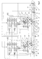
- Multi-color printing machines 1 generally have four color printing units 6, 6 ', 6 ", 6"'', as shown in FIG. 4.
- FIG. 1 In the illustration of FIG. 1, only two color printing units 6 and 6 'have been drawn in, since this is sufficient for the explanation of the function according to the invention.
- the illustration must be supplemented mentally in such a way that four or sometimes more color printing units 6, 6', 6 ", 6 ''' register correspondence must be brought in the manner described.
- Each of the illustrated color printing units 6, 6 ', ... has an image cylinder 2, 2', ..., which is assigned a device 3, 3 ', ... for generating images. It acts it is usually digital imaging, in the form of electrostatic latent images or by direct or other digital image generation, such as for example by ink jet.
- Multi-color printing machines 1 can be designed in this way be that the transfer of the images from the image cylinders 2, 2 ', ... immediately on Printing substrates 15 takes place.
- the multicolor printing machine 1 shown has additionally via image transfer cylinders 13, 13 ', ..., the images from the image cylinders 2, 2 ', ... at image transfer points 53, 53', ... on the image transfer cylinders 13, 13 ', ... are transmitted. Of the image transfer cylinders 13, 13 ', ... the images are then finally transferred to the printing substrates 15 at image transfer points 5, 5 ', 5' ', 5' ''.
- the printing substrates 15 are transported by a carrier 4 in the direction of the arrow 33. They pass through the image transmission points 5, 5 ', 5 “, 5"' 'one after the other each image transfer point 5, 5 ', 5 “, 5" “of a color printing unit 6, 6', 6", 6 "" becomes one Partial color image 7, 7 ', ... transferred to the printing substrate 15. That through register settings Problem to be solved is that the partial color images 7, 7 ', ... extremely have to be printed exactly on top of each other in order to achieve high print quality. At electrostatic or similar digital printing processes will print the images on the Image cylinders 2, 2 ', ... by means of devices 3, 3', ... new for each individual print generated, transmitted and then removed by a device 61, 61 ', ... again. A such device 61, 61 ', ... is shown in FIGS. 2 and 4.
- FIGS. 1, 2 and 4 set Embodiment and are to achieve completeness of a Put machine representation together.
- a register setting is made on printing presses digital printing process in that the image generation points 11, 11 ', ... at the individual color printing units 6, 6 ', 6 ", 6' '' can be selected such that at Transfer of the images on the printing substrates 15 a register accuracy is achieved.
- times have been recorded for this purpose, which are a printing substrate needed until it reaches the image transfer points. These times were with the times in which an image from its creation to Transfer to the print substrate required. So there was an acquisition Printing substrate and it was then the time of imaging for each color printing unit calculated so that it achieves the registration of all part-color images is.
- the invention now provides for achieving register matching of the partial color images 7, 7 ', ... that the positions of the generation 11, 11', ... of the partial color images 7, 7 ', ... to each other and to the positions 25, 25', ... of a printing substrate 15 in Be matched. All positions 11, 11 ', ..., 8, 8', ..., 9, 9 ', ..., 12, 12', ..., 14, 14 ', ..., 22, 22', ..., 25, 25 ', ... as paths or as Defined angular positions and for calculating the positions of generation 11, 11 ', ... of the partial color images 7, 7', ... are used.
- the position assignment according to the invention begins with a sensor 23 as the detection point 23 serves for the front edge 24 of a printing substrate 15.
- a sensor 44 for Detection of a printing substrate 15 is already arranged in front of the carrier 4
- Printing substrates 15, which are fed to the printing press 1, are already on their way to detect the printing press 1 and the calculation process for the assignment of To set partial color images 7, 7 ', ... in motion.
- the device for register setting calculates the starting point 23 Positions 25, 25 ', ... for example as paths 22, 22', ..., which the printing substrate 15 on the carrier 4 must travel. These positions 25, 25 ', ... are defined in that when they are reached by a printing substrate 15, the imaging of the image cylinders 2, 2 ', ... starts. Positions 25 and 25 'are, so to speak, the positions of equality the leading edge 24 of a printing substrate 15 with the leading edge 10 of the partial color images 7, 7 ', ... up to the image transmission points 5, 5', 5 "and 5 '' '- or the Angular equality expressed in the above. Angles. Needless to say normally, as shown in FIG. 4, at least 4 color printing units 6, 6 ', 6 ′′, 6 ′′ ′′ are brought into this positional correspondence is a simplification.
- the right printing substrate 15 still bears no partial color image
- the middle printing substrate 15 the partial color image 7 of the color printing unit 6 and the left printing substrate 15 both partial color images 7 and 7 '.
- the pressure will then on further color printing units 6 "and 6 '' 'and possibly also by special colors completed.
- the transport of the printing substrates 15 takes place by means of the Carrier 4 instead, which is designed as a belt running on rollers 52 and 52 '.
- a The roller is the drive roller 52 and the other roller is a guide roller 52 '.
- For transmission of the partial color images 7, 7 ', ... on the printing substrates 15 are at the image transfer points 5, 5 ', 5 ", 5" "attached to the impression cylinder 20. These serve the Transfer of electrically charged color particles in printing processes using electrostatic latent images on the printing substrates 15. They are not in FIGS. 1 and 2 is shown, but its location can be seen in FIG. 4.
- Fig. 1 are the directions of rotation 16, 16 ', ... the image cylinder 2, 2', ... and the directions of rotation 60, 60 ', ... the image transfer cylinder 13, 13', ... drawn.
- the direction of conveyance of the carrier 4 results from the arrow 33.
- FIG. 2 shows the basic structure of a register setting device for performing the setting according to the invention of positions 8, 8 ', ..., 9, 9', ..., 12, 12 ', ..., 14, 14',. .., 22, 22 ', ..., 25, 25', ....
- Whose positions can be determined by a sensor 27, which as. Angle position transmitter is designed to be detected.
- a sensor 32 can also be arranged on the carrier 4, which detects path markings of the carrier 4.
- Detection of register marks 17, 17 ′, 17 ′′, 17 ′′ ′′ by a sensor 29 can also be used for position detection.
- a sensor designed as an angular position transmitter is used to detect the positions of the image cylinders 2, 2 ′, 26, 26 ', ... and for detecting the position of the image transmission cylinders 13, 13', ... sensors 28, 28 ', also in the form of angular position sensors.
- the cylinders 2, 2', ..., 13, 13 ', ... sensors 26, 26', ... which detect the path by way of markings. This is indicated in Fig. 4 by the arrangement of such sensors 26, 26 ', ....
- Upstream of the carrier 4 is a conveyor belt 45 for feeding printing substrates 15 to the printing press 1.
- a printing substrate 15 passes the sensor 44, the assignment of positions 8, 8 ', ..., 9, 9', ... is calculated. , 12, 12 ', ..., 14, 14',, 22, 22 ', ..., 25, 25, ... started.
- the front edge 24 of the printing substrate 15 hits the sensor 23, the calculations are ready and devices 46, 46 ', ... are started which record the travel of the paths 22 and 22' and then the start signals 48 and Give 48 'for the image starts 10 and start signals 49 and 49' for the areas 10 ', 10', ..., 10 n of the partial color images 7, 7 '.
- the paths 22, 22 ', ... In order to detect the paths 22, 22 ', ...
- the devices 46, 46 ', ... are connected to all position-sensing sensors. These are the sensors 26, 26 ', ... for detecting the positions of the image cylinders 2, 2', ..., the sensor 27 for detecting the positions of the carrier 4 and the sensors 28, 28 ', ... for detecting of the positions of the image transfer cylinders 13, 13 ', .... Furthermore, the devices 46, 46', ... for calculating the positions 25, 25 ', ... are connected to setting devices 30, 30', ... which calculate positions 12, 12 ', ... and 14, 14', ... for the beginning of the picture 10.
- the start signals 48, 48 ', ... for the image starts 10 and the start signals 49, 49', ... for the areas 10 ', 10 ", 10''', ..., 10 n of the partial color images 7, 7 ', ..., into which the image area is divided, are given when the front edge 24, or the future image start of the printing substrate 15, the positions 25, 25', ... of the start of the imaging of the image cylinders 2, 2 ',. ..
- the setting devices 30 serve , 30 ', ... for the calculations of the paths 8, 8', ..., 9, 9 ', ... of the image beginnings 10 and the setting devices 31, 31', ... for the calculations of the paths 8, 8 ', ..., 9, 9', ... of the areas 10 ', 10 ", ..., 10 n of the partial color images 7, 7', ....
- a first setting of the positions for the image production 11, 11 ', ... is thereby made that the setting devices 30, 30 ', ..., 31, 31', ... all relevant data 8, 8 ', ..., 9, 9', ..., 12, 12 ', ..., 14, 14', ..., 22, 22 ', ..., 25, 25 ', ... receive.
- the capture and assignment of the positions for example the paths or angles 8, 8 ', ..., 9, 9', ... and 12, 12 ', ..., 14, 14', ..., 22, 22 ', ..., 25, 25', ... is sufficient.
- the setting devices 30, 30 ', ... have machine-specific nominal values 34, 34', ... of positions 8, 8 ', ..., 9, 9', ... of the beginning of the picture 10.
- the setting devices 31, 31 ', ... also have machine-specific nominal values 35, 35', ... with regard to positions 8, 8 ', ..., 9, 9', ... of the areas 10 ', 10 ",. .., 10 n of the partial color images 7, 7 ', ....
- These machine-specific nominal values 35, 35', ... are constantly corrected in order to achieve high accuracy, for the first time before a printing process is carried out
- the setting devices 30, 30 ', ..., 31, 31', ... receive correction values 37, 37 ', ... for positions 9, 9', ... the image transfer cylinder 13, 13 ', ....
- These correction values 37, 37', ... come from the sensors 28, 28 ', ... for detecting the angular positions or the paths of the surfaces of the image transfer cylinders 13, 13', .. ..
- the distances 64 between the color printing units 6, 6 ', 6 ", 6'" and the position of the sensor 23 can also be entered as machine-specific nominal values. Corrections of the same may be necessary due to various influences, for example due to measured temperatures or due to mechanical stresses in the printing press 1.
- These correction values 38, 38 ', ... can be empirical values for Types of paper, for toner application, image widths, paper widths, the fact that in Backprint is printed, temperature, tensions in machine parts, the displacement a printing substrate 15 on the carrier 4 and so on. In this regard, the referenced above description.
- These correction values 38, 38 ', ... are empirical values ready. You can send an input device, not shown, to the Setting devices 30, 30 ', ..., 31, 31', ... are given or it is possible they based on a measurement, for example a temperature or a voltage Setting devices 30, 30 ', ..., 31, 31', ... to be transmitted.
- Both the machine-specific nominal values 34, 34 ', ..., 35, 35', ... and the Correction values 38, 38 ', ... can be available as calibration tables.
- Others already described above Assignments are possible, however, then several calibration tables have to be assigned to the Calculation of the image generation points 11, 11 ', ... on the image cylinders 2, 2', ... included become.
- Calibration tables for other values are then different, for example Assigned temperatures or different voltages. You can also these calibration tables can be assigned to angular positions of the image cylinders 2, 2 ', ...
- Experience values stored correction values 38, 38 ', ... are as files 39, 39', ... retrievable filed.
- a series of spaced-apart elements 18 can be printed in which successively one element 18 is printed by a color printing unit 6, 6 ', 6 ", 6"' ' becomes. However, it is also possible that color printing units 6, 6 ', 6 ", 6' '' one after the other print multiple spaced elements 18. If the register marks 17, 17 ', 17 ", 17 '' 'are not printed as continuous tapes, so the distances between the individual register mark groups can be recorded.
- the register marks 17, 17 ', 17 ", 17 '' ' can be printed directly on the carrier 4, as long as no printing substrates 15 are on it, they can be on those not covered by printing substrates 15 Places of the carrier 4 are printed, on test sheets or on non-image areas of the Printing substrates 15, e.g. B. on the edges.
- the measured values of the sensor 29 are transmitted to devices 40, 40 ', ... for determining the corrections 42, 42', ... for the image beginnings 10, these devices 40, 40 ', ... the corrections 42, 42' , ... to the setting devices 30, 30 ', ...
- These devices 41, 41 ', ... also give the corrections 43, 43', ... to the setting devices 31 , 31 ', ..., so that the positions for the defined areas 10', 10 ", ..., 10 n are corrected based on this feedback.
- FIG. 2 is only for the sake of clarity limited to two printing units 6, 6 ', in fact there are usually four Printing units 6, 6 ', 6 ", 6' '' available. Correspondingly longer must of course then the carrier 4 can be designed.
- the conveyor belt 45 for feeding a Printing substrate 15 to printing machine 1 is shown shortened, path 21 one Print substrate from sensor 44 to sensor 23 is significantly longer to during The calculation process for positions 8, 8 ', ..., 9, 9', ..., 12, 12 ', ..., 14, 14 ', ..., 22, 22', ..., 25, 25 ', ....
- Usually four printing units 6, 6 ', 6 ", 6' '' are present, are also those described above, those shown Elements 6 and 6 'associated with printing units are present four times. Or it is a Calculator provided that contains all elements.
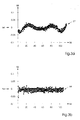
- 3a shows register deviations in a machine that was set on the basis of a time measurement.
- the deviations 55 from the nominal value 54 of a register are plotted when measuring points are detected along a path 56 in the transport direction 33.
- the measuring points 57 show oscillation-like deviations from the nominal value 54, which is shown as the zero line.
- 3b shows register deviations in a printing press 1 which was set according to the principle according to the invention. Due to the register setting made there according to positions, a setting with significantly smaller deviations is achieved. Here, too, the deviations 55 from the nominal value 54 are plotted against the path 56 of measuring points along the transport direction 33. The vibration-like deviations as in the time control do not occur here, even if the cause, for example the poles of the electric motor of a drive machine, is still present. The reason is that such vibrations are based on the assignment of positions to times and therefore cannot influence control.
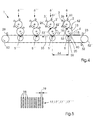
- FIGS. 1 and 2 show a schematic illustration of a multicolor printing machine 1 with four color printing units, 6, 6 ', 6 ", 6"''. This is the normal design of a multicolor printing machine 1, but there may also be more printing units.
- the reference numerals are identical with those already described, all components of the machine shown having already been discussed in the explanations for FIGS. 1 and 2.
- the printing machine shown as an exemplary embodiment has the four color printing units 6, 6 ', 6 ", 6"", where each the elements acc. 1 and 2 are assigned.
- the distance 64 between two color printing units 6, 6 'or 6', 6 "or 6", 6 '' '.
- Such a distance 64 is expedient dimensioned such that a runout of the drive roller 52 on all printing units 6, 6 ', 6 '', 6 '' 'comes into play simultaneously. Through this even influence avoided an impact of this error.
- the scope of the Drive roller 52 correspond to the distance 64, it can also be a fraction of this Distance 64 or a whole multiple. From the machine dimensioning is likely to be an identity of the extent with the distance 64 or a whole multiple in Question come.
- register marks 17, 17 ', 17 ", 17"'' which are particularly useful for position detection.
- These register marks 17, 17', 17 ", 17”" have spaced elements 18. They represent, so to speak, a scale that specifies positions defined as a path or, for example, as an angular interval and thus makes the position of the partial color images 7, 7 ', 7 ", 7"''relative to one another and to the printing substrate 15 detectable.
- Fig. 6 shows a schematic diagram for register mark detection. From the color printing units 6, 6 ', 6 ", 6' '' - only one is shown symbolically - becomes one at a time Register mark 17, 17 ', 17 ", 17”' printed. These are by a sensor 29 for Detection of register marks 17, 17 ', 17 “, 17”' with respect to their position a reference line 66 is defined in the register control, which is a substrate 15 on the Carrier 4 is assigned.
- FIG. 7 shows an example of a time-independent position assignment.
- the angular positions 68 of the image cylinder and the image transfer cylinder are plotted against the positions 69 of the carrier 4 for printing substrates.
- the angular position 70 of an image cylinder 2 and the angular position 71 of an image transfer cylinder 13 were shown.
- the angular positions of the further image cylinders 2 'etc. would have to be drawn in by means of curves which are shifted with respect to curves 70 and 71. This has been omitted for the sake of clarity.
- the illustration shows that an angular position of an image cylinder 2 and an angular position of an image transfer cylinder 13 belong to each position 69 of the carrier 4 for printing substrates 15. In this way, a time-independent position assignment is carried out in order to start certain processes in the correct positions.
- the first preparation for printing is initiated in position 72, this is the position of the detection of a printing substrate 15 by a sensor 44, which registers the feeding of the printing substrate 15 to the multicolor printing machine 1. From this point in time, the image generation 11, 11 ', ... of the partial color images 7, 7', ... is calculated, the relative assignments being calculated.
- a position 73 the printing substrate 15 is detected by the sensor 23 and thus its exact position on the carrier 4 is determined, as a result of which an exact assignment of the image generations 11, 11 ', ... of the partial color images 7, 7', ... to the carrier 4 is possible.
- the print substrate travels the path 21 between the position 72 and the position 73.
- the path or the angular position of the drive roller 52 is calculated in order to determine the position 25.
- This is the position of the carrier 4 at which the start of image generation 11 of a partial color image 7 on the image cylinder 2 begins.
- the transfer of the partial color image 7 from the image cylinder 2 to the image transfer cylinder 13 takes place.
- the carrier 4 reaches the position 75 for the start of the transfer of the partial color image 7 from the image transfer cylinder 13 on a substrate 15.
- the paths 14 and 12 of the carrier 4 are assigned angular positions 8 of the image cylinder and angular positions 9 of the image transfer cylinder 13.
- the position assignments of the defined areas 10, 10 ', 10 ", ..., 10 n of all partial color images 7, 7', ... are carried out in a manner corresponding to the beginning of the image 10 of the partial color image 7.
- the position assignments according to the invention do not mean that the Path lengths on the cylinders 2, 2 ', ..., 13, 13', ... and the carrier 4 are the same since it in the transmissions of the partial color images 7, 7 ', ..., for example from one Image cylinder 2, 2 ', ..., to an image transfer cylinder 13, 13', ... to one Overdrive is coming.
- the illustrated embodiment serves only to explain the invention and at the same time represents an advantageous embodiment
- the method and the device of the invention can of course be varied Be realized in one machine. Not just alternatives regarding the Position registration, which were mentioned, are possible, also the concrete registration and Processing of the data can of course be done in different ways become.
Abstract
Description
Die Erfindung betrifft ein Verfahren zur Registereinstellung an einer Mehrfarbendruckmaschine mit verschiedenen Druckfarben zugeordneten Farbdruckwerken mit Bildzylindern, Einrichtungen zur Erzeugung von Bildern, insbesondere von elektrostatischen latenten Bildern, auf den Bildzylindern, einem Träger für Drucksubstrate und Bildübertragungsstellen für die Übertragung der Teilfarbenbilder von den Farbdruckwerken auf die Drucksubstrate, wobei eine Zuordnung der Bilderzeugungen auf den Bildzylindern zur Erzielung einer Registerübereinstimmung der Teilfarbenbilder beim Druck vorgenommen wird.The invention relates to a method for register adjustment on a multi-color printing press with different printing inks assigned color printing units with image cylinders, Devices for generating images, in particular electrostatic latent images, on the image cylinders, a carrier for printing substrates and image transfer points for the transfer of the partial color images from the color printing units to the printing substrates, with an assignment of the image generation on the image cylinders to achieve a register match of the part-color images when printing becomes.
Die Erfindung betrifft weiterhin eine Vorrichtung zur Registereinstellung nach dem oben beschriebenen Verfahren an einer Mehrfarbendruckmaschine mit verschiedenen Druckfarben zugeordneten Farbdruckwerken mit Bildzylindern, Einrichtungen zur Erzeugung von Bildern, insbesondere von elektrostatischen latenten Bildern, auf den Bildzylindern, einem Träger für Drucksubstrate und Bildübertragungsstellen für die Übertragung der Teilfarbenbilder von den Farbdruckwerken auf Drucksubstrate, Sensoren zur Positionserfassung, sowie mindestens einer Einstellungseinrichtung zur Zuordnung der Positionen der Bilderzeugungsstellen auf den Bildzylindern zu den Drucksubstraten zur Erzielung einer Registerübereinstimmung der Teilfarbenbilder beim Druck. Weiterhin betrifft die Erfindung eine entsprechend ausgestattete Mehrfarbendruckmaschine.The invention further relates to a device for register adjustment after Process described above on a multi-color printing machine with different Color printing units assigned to printing inks with image cylinders, devices for Generation of images, in particular electrostatic latent images, on the Image cylinders, a carrier for printing substrates and image transfer points for the Transfer of the partial color images from the color printing units to printing substrates, sensors for position detection and at least one setting device for Assignment of the positions of the image generation points on the image cylinders to the Printing substrates to achieve register matching of the partial color images when printing. The invention further relates to a suitably equipped multicolor printing machine.
Der Druck farbiger Darstellungen, insbesondere farbiger Bilder, erfolgt dadurch, daß mehrere Teilfarbenbilder übereinandergedruckt werden. Dies sind in der Regel die Farben Gelb, Magenta und Zyan sowie Schwarz. Bei Bedarf kommen noch Sonderfarben hinzu. Durch das Übereinanderdrucken dieser Farben lassen sich alle Farbkompositionen erzielen. Die Qualität der Drucke hängt dabei wesentlich von dem register-haltigen Übereinanderdrucken der Teilfarbenbilder ab. In herkömmlichen, nicht automatisierten Druckverfahren werden die Druckformen mittels Probedrucken und mit diesen mitgedruckten Registermarken so lange korrigiert, bis ein exaktes Übereinanderdrucken, also eine Registerhaltigkeit des Drucks, erzielt ist.The printing of colored representations, in particular colored images, takes place in that several partial color images are printed on top of each other. These are usually the ones Colors yellow, magenta and cyan as well as black. Special colors are also available if required added. By printing these colors on top of each other you can create all color compositions achieve. The quality of the prints depends largely on the register Print the partial color images on top of each other. In conventional, not automated Printing processes are the printing forms by means of test printing and with corrected the printed register marks until an exact overprinting, that is, a register of the print is achieved.
Bei digitalen Druckverfahren werden die Bildzylinder mittels jeweils einer Bilderzeugungseinrichtung mit Bildpunkten beschrieben, indem beispielsweise elektrostatische Aufladungen erzeugt und diese mit anhaftenden Farbpigmenten versehen werden. Danach werden die Farbpigmente auf ein Drucksubstrat übertragen. Bei digitalen Druckverfahren kann die Registerhaltigkeit dadurch erzielt werden, daß die Bilderzeugungseinrichtungen entsprechend gesteuert werden. Da die Bebilderung für jeden Druck neu erfolgt, muß nicht wie bei herkömmlichen Druckverfahren eine einmalige Einstellung vorgenommen werden, sondern es kann eine Voreinstellung und eine Regelung vorgesehen sein, die für jeden einzelnen Druck Korrekturen vornimmt. Selbstverständlich gilt dies nicht nur für die Aufbringung elektrostatischer latenter Bilder sondern auch alle anderen Druckverfahren, bei denen mittels einer digitalen Steuerung Bildpunkte aufgebracht werden.In digital printing processes, the image cylinders are each made by means of an image generation device described with pixels, for example by electrostatic Charges generated and these are provided with adhering color pigments. The color pigments are then transferred to a printing substrate. With digital The printing process can maintain register accuracy by using the image forming devices be controlled accordingly. Since the illustration for every print new, does not have to be a one-off as with conventional printing processes Setting can be made, but it can be a preset and a Regulation should be provided, which makes corrections for each individual print. Of course, this does not only apply to the application of electrostatic latent materials Images but also all other printing processes, in which by means of a digital Control pixels can be applied.
Für ein elektrostatisches Druckverfahren der eingangs genannten Art wurde daher von der US 5, 287, 162 vorgeschlagen, Registermarken vorzugsweise auf den Träger für die Drucksubstrate zu drucken und diese durch eine Vorrichtung zu erfassen. Ermittelt werden dabei die Zeiten, die die Registermarken von der Erzeugung durch die Bilderzeugungseinrichtungen bis zu einer Erfassungsstelle brauchen. Diese Zeiten werden dann herangezogen, um die Zeitpunkte zu bestimmen, zu denen die Bilderzeugungseinrichtungen an den einzelnen Bildzylindern deren Bebilderung vornehmen, um die Registerhaltigkeit nach Übertragung der Bilder auf ein Drucksubstrat zu erzielen. For an electrostatic printing process of the type mentioned at the outset, of US 5, 287, 162 proposed register marks preferably on the carrier for the Print substrates and capture them by a device. Ascertained are the times that the registration marks are generated by the image generation devices up to a registration point. These times will be then used to determine the times at which the imaging devices undertake the imaging of the individual image cylinders in order to achieve the To achieve register accuracy after transferring the images to a printing substrate.
Da eine Erzielung einer Übereinstimmung bezüglich der Bebilderung der Bildzylinder bei Geschwindigkeitsdifferenzen bezüglich der Oberflächen der Bildzylinder zu Ungenauigkeiten führt, wurde von der US 5, 287, 162 vorgeschlagen, Eichtabellen mit Zeiten aufzunehmen, die verschiedenen Winkelstellungen der Bildzylinder zugeordnet sind, um mit Hilfe dieser Eichwerte regelmäßig auftretende Schwankungen - die meist von Unrundheiten der Zylinder herrühren - zu eliminieren, und auf diese Weise die Korrekturen für jeden einzelnen Druck vorzunehmen.Since achieving agreement on the imaging of the image cylinders with speed differences with respect to the surfaces of the image cylinders to inaccuracies leads has been proposed by US 5, 287, 162, calibration tables with times to record the different angular positions of the image cylinders, in order to use the calibration values to make regular fluctuations - mostly from Out of roundness of the cylinders result - to eliminate, and in this way the Make corrections for each individual print.
Da die für hohe Druckqualitäten erforderliche Registerhaltigkeit eine äußerst hohe Präzision erfordert, sind derartige Eichtabellen, in die Zeitwerte eingestellt werden, jedoch unzureichend. Nicht berücksichtigbar sind dabei Unregelmäßigkeiten, die sich nicht in Differenzen von Zeitspannen, welche Drehwinkeln der Bildzylinder zugeordnet werden können, niederschlagen. Gerade für letztere hilft auch nicht ein Vorschlag der US 5, 287, 162, die Eichtabellen immer wieder neu zu erstellen, da dadurch nur ein langfristiges und langsames Triften der Werte, aber keine kurzfristigen, nicht Winkelstellungen der Bildzylinder zuordenbare Differenzen berücksichtigt werden können.Because the register accuracy required for high print quality is extremely high Precision is required, such calibration tables, in which time values are set, however insufficient. Irregularities that are not taken into account not in differences of time spans which rotation angles are assigned to the image cylinder can be put down. For the latter in particular, a suggestion from the does not help US 5, 287, 162, to recreate the calibration tables again and again, because this means only one long-term and slow drifting of values, but no short-term, not angular positions the image cylinder assignable differences can be taken into account.
Ein typisches Beispiel für solche Unregelmäßigkeiten, die sich nicht in Differenzen von Zeitspannen niederschlagen, sind Schwankungen in der Geschwindigkeit des Antriebssystems, da die Zuordnung derselben zu bestimmten Drehwinkeln der Bildzylinder oder anderer Zylinder nicht möglich ist, weil diese Schwankungen keine Synchronität zu den Winkelstellungen der Bildzylinder oder anderer Zylinder aufweisen. Eine Regelung durch eine Eichtabelle der vorgeschlagenen Art mit Zeitwerten, die den Drehwinkeln der Bildzylinder zugeordnet ist, würde somit eher Fehler produzieren als Fehler zu eliminieren. So wurde bei Untersuchungen beispielsweise festgestellt, daß die Pole der Antriebselektromotoren als Verursacher von frequenzartigen Geschwindigkeitsschwankungen des Antriebs auftreten, welche aufgrund der unterschiedlichen Übertragungswege auch kein zeitgleiches Auftreten an allen Bildzylindern aufweisen und daher zur Zeit-Positions-Differenzen an den einzelnen Bildzylindern führen. Diese frequenzartigen Schwankungen reichen aus, um Fehler in der Registereinstellung zu verursachen. A typical example of such irregularities that do not differ in differences from Periods of time, fluctuations in the speed of the drive system, since the assignment of the same to certain angles of rotation of the image cylinder or other cylinders is not possible because these fluctuations are not synchronous with the Have angular positions of the image cylinder or other cylinders. A regulation through a calibration table of the proposed type with time values representing the angles of rotation the image cylinder is assigned, would therefore produce errors rather than errors eliminate. For example, studies have found that the poles of the Electric drive motors as the cause of frequency-like speed fluctuations of the drive occur due to the different transmission paths also have no simultaneous occurrence on all image cylinders and therefore lead to time-position differences on the individual image cylinders. These frequency-like Variations are sufficient to cause errors in the register setting.
Derartige Fehler können bereits am Bildanfang auftreten oder sich in der Bildqualität als Fehler in Teilbereichen von Bildern, beispielsweise als querstreifenförmige Registerungenauigkeiten bemerkbar machen. Da sich solche frequenzartigen Schwankungen des Antriebssystems mit anderen Fehlern, wie die Unrundheiten von Bildzylindern, überlagern, ist es auch nicht mehr mit vertretbarem Aufwand möglich, Eichtabellen zur Korrektur zu erstellen. Diese könnten sich nicht mehr an den Winkelstellungen der Bildzylinder oder anderer Zylinder für eine Umdrehung oder für eine überschaubare Folge von Umdrehungen orientieren, sondern es müßte - soweit dies durch die Komplexität überhaupt möglich ist - einen Verlauf von Eichwerten über komplexe Maschinenkonstellationen bis zum Auftritt einer Wiederholungssituation ermittelt werden. Einer solchen Erstellung von Korrekturwerten über längere Zeiträume steht aber wiederum entgegen, daß es auch noch weitere Fehlerursachen wie Unregelmäßigkeiten der Führung des Trägers und vor allem auch langfristige Änderungen gibt, wie Temperaturänderungen, Änderung von mechanischen Spannungen in der Maschine, Änderungen der Papierart, der Tonermenge usw. Eine derartige "bunte Mischung" von Fehlern, die sich kurzfristig ändern und synchron zu den Winkelstellungen von Zylindern verhalten, mit Fehlern, die sich ebenfalls kurzfristig aber nicht synchron mit den Winkelstellungen ändern und langfristigen asynchronen Änderungen, steht der Erzielung einer hohen Präzision durch eine Korrektur mit Hilfe der vorgeschlagenen Eichtabellen mit Zeitwerten entgegen.Such errors can occur at the beginning of the picture or can change in quality Errors in partial areas of images, for example as cross-strip-like register inaccuracies to make noticable. Since such frequency-like fluctuations of the Drive system with other errors, such as the out-of-roundness of image cylinders, it is no longer possible with reasonable effort to calibrate calibration tables Create correction. These could no longer be determined by the angular positions of the Image cylinder or other cylinder for one revolution or for a manageable Orientation sequence of revolutions, but it should - as far as this by the Complexity is possible at all - a course of calibration values over complex Machine constellations determined until a repetition situation occurs become. Such a creation of correction values over longer periods is available but again counter that there are other causes of error such as irregularities the leadership of the carrier and, above all, long-term changes, such as Temperature changes, change of mechanical stresses in the machine, Changes in paper type, amount of toner, etc. Such a "colorful mix" of Errors that change at short notice and synchronized with the angular positions of cylinders behave with errors that are also in the short term but not in sync with the Changing angular positions and long-term asynchronous changes is the achievement high precision through a correction using the suggested calibration tables with current values.
Der Erfindung liegt daher die Aufgabe zugrunde, ein Verfahren, eine Vorrichtung und eine Druckmaschine der eingangs genannten Art derart auszugestalten, daß eine hohe Präzision der Registereinstellung mit vertretbarem Aufwand, insbesondere möglichst ohne Makulaturdrucke, erzielbar ist. Es soll dabei sowohl eine schnelle und möglichst exakte Voreinstellung als auch eine ständige schnelle Korrektur der Registereinstellung ermöglicht werden. The invention is therefore based on the object of a method, a device and to design a printing press of the type mentioned in such a way that a high Precision of register setting with reasonable effort, especially if possible without waste prints, can be achieved. It should be both quick and possible exact presetting as well as constant quick correction of the register setting be made possible.
Die Aufgabe wird bezüglich des Verfahrens erfindungsgemäß dadurch gelöst, daß eine zeitunabhängige Positionszuordnung der Bilderzeugungen auf den Bildzylindern zu den Drucksubstraten mindestens eines definierten Bereichs aller Teilfarbenbilder erfolgt.The object is achieved with respect to the method in that a time-independent position assignment of the image generation on the image cylinders to the Print substrates of at least a defined area of all part color images.
Bezüglich der Vorrichtung wird die Aufgabe erfindungsgemäß dadurch gelöst, daß die Sensoren zur Erfassung der Positionen von bild- und substrattragenden Elementen ausgebildet sind und daß mindestens eine Einstellungseinrichtung derart ausgebildet ist, daß sie die Positionen der Bilderzeugungen auf den Bildzylindern zu den Drucksubstraten bezüglich mindestens eines definierten Bereichs der Teilfarbenbilder zeitunabhängig zuordnet.With regard to the device, the object is achieved in that the Sensors for the detection of the positions of image- and substrate-bearing elements are formed and that at least one setting device is designed such that they match the positions of the imaging on the imaging cylinders to the printing substrates independent of time with respect to at least one defined area of the partial color images assigns.
Ebenso wird eine Mehrfarbendruckmaschine mit einer derartigen Vorrichtung vorgeschlagen.A multi-color printing machine with such a device is also proposed.
Der Erfindung liegt die Beobachtung zugrunde, daß eine Voreinstellung und/oder Regelung eines Registers, bei welchen erfaßte Zeiten zueinander in Bezug gesetzt werden, zu einer Erhöhung der Komplexität von Fehlerüberlagerungen führt, da zu den eigentlichen Registerfehlerursachen noch Fehler durch die Bestimmung von Positionen durch Zeiten hinzugefügt werden. Diese Hinzufügung einer weiteren Fehlerursache ist für Gegenmaßnahmen deshalb problematisch, weil es sich bei den letztgenannten Fehlern um kurzfristig auftretende und sich asynchron zu den Winkelstellungen der Bildzylinder verhaltende Fehler handelt.The invention is based on the observation that presetting and / or regulation of a register, in which recorded times are related to one another an increase in the complexity of error overlays leads to the actual Register error causes errors due to the determination of positions by times to be added. This addition of another cause of error is for countermeasures problematic because the latter errors are occurring at short notice and asynchronous to the angular positions of the image cylinders cautious error.
Der Erfindung liegt weiterhin die Erkenntnis zugrunde, daß, wenn man statt der Zeiten die Positionen unmittelbar zueinander in Bezug setzt, die sich nicht synchron zu Winkelstellungen von Zylindern verhaltenden Fehler zu einem großen Teil nicht mehr auftreten, da sie von der Zeit-Position-Zuordnung herrühren. Sie beeinflussen also eine Einstellung des Registers dann nicht, wenn man eine unmittelbare gegenseitige Zuordnung von Positionen zur Steuerungs- oder Regelungsgrundlage macht. Solche unmittelbare Positionszuordnungen können beispielsweise derart ausgebildet sein, daß man Entfernungen bzw. Wege oder Winkelstellungen einander zuordnet. Durch die erfindungsgemäße Maßnahme haben die frequenzartigen Schwankungen des Antriebssystems oder ähnliche Fehlerquellen keinen Einfluß mehr auf die Registereinstellung, da die Positionen unmittelbar und nicht mehr auf dem Umweg über Zeiten erfaßt werden.The invention is further based on the knowledge that if one instead of the times positions directly related to each other that are out of sync For the most part, angular positions of cylinders no longer cause errors occur because they come from the time-position assignment. So you influence one Setting the register does not occur when there is an immediate mutual assignment from positions to the basis of control or regulation. Such immediate Position assignments can for example be designed such that one Associates distances or paths or angular positions. By the invention The frequency-like fluctuations of the drive system have a measure or similar sources of error no longer influence the register setting, because the positions are recorded immediately and no longer by way of detours.
Durch die Erfindung wird erreicht, daß die noch verbleibenden kurzfristigen Schwankungen sich im wesentlichen synchron zu den Winkelstellungen der Bildzylinder oder anderer Zylinder, bezogen auf eine Umdrehung oder eine kurze Abfolge von Umdrehungen, wiederholen. Es ist somit auch möglich, Eichtabellen für die Bilderzeugung in jedem Fardruckwerk zu erstellen, die für eine gewisse Dauer Gültigkeit haben. Langfristige Änderungen können dann während des Drucks dadurch berücksichtigt werden, daß Eichtabellen, welche auf einer Erfassung von Positionen beruhen, immer wieder erneuert werden. Eine solche Erneuerung von Eichtabellen korrigiert ein langsames Triften. Die Eichtabellen sind erst durch die erfindungsgemäße Maßnahme nahezu fehlerfrei erstellbar, da die kurzfristigen, sich asynchron zu den Winkelstellungen der Bildzylinder verhaltenden Fehler größtenteils vermieden sind und die auf Positionszuordnung basierende Einstellung der Register nicht mehr beeinflussen. Selbstverständlich ist aber die Erfindung nicht auf Eichtabellen beschränkt. Eichtabellen sind lediglich eine Ausgestaltung, jedoch sind diese durch die Erfindung erst für eine Präzisionseinstellung brauchbar.The invention ensures that the short-term fluctuations still remaining are essentially synchronous with the angular positions of the image cylinders or other cylinders, related to one revolution or a short sequence of revolutions, to repeat. It is therefore also possible to use calibration tables for image generation in to create each printing unit that is valid for a certain period. Long term Changes can then be taken into account during printing by that calibration tables, which are based on the acquisition of positions, again and again to be renewed. Such a renewal of calibration tables corrects a slow one Drift. The calibration tables are almost only through the measure according to the invention error-free, because the short-term, asynchronous to the angular positions of the Image cylinder-related errors are largely avoided and that on position assignment no longer influence the register settings. Of course However, the invention is not limited to calibration tables. Calibration tables are only an embodiment, but these are only for precision adjustment by the invention useful.
Durch die Erfindung ist es möglich, nahezu alle Fehlerquellen von bild- oder drucksubstratübertragenden Elementen zu erfassen und zu eliminieren, da die kurzfristigen Fehler größtenteils auf die synchron zu Winkelstellungen auftretenden Fehler reduziert sind und sich die im Verhältnis zu einer Wiederholung pro Umdrehung längerfristigen Fehler von letzteren trennen lassen. Dabei kommt es nicht darauf an, ob die noch verbleibenden Fehler auf Durchmesserfehlern oder Unwuchten von Bildzylindern oder weiteren die Bilder übertragenden Zylindern beruhen. Es lassen sich auch Übertragungsfehler durch das Verhalten elastischen Materials wie das von Zylindermänteln, durch unterschiedliche Anpreßkräfte oder durch Differenzen bei mechanischen Spannungen von Trägern für Drucksubstrate oder der Zustellung einer Gegendruckwalze, die der Bildübertragung auf ein Substrat dient, erfassen und eliminieren, da diese Fehler den Winkelstellungen der jeweiligen bild- oder substrattragenden Bauteile in synchrone Weise zuordenbar und daher durch jeweils zu erstellende Eichtabellen korrigierbar sind.The invention makes it possible to eliminate almost all sources of errors in image or print substrate transmission Capture and eliminate items since the short term Most of the errors are reduced to errors that occur synchronously with angular positions and the longer-term in relation to one repetition per revolution Have errors separated from the latter. It does not matter whether they are still remaining errors on diameter errors or imbalance of image cylinders or further cylinders transferring the images are based. There can also be transmission errors through the behavior of elastic material like that of cylinder jackets different contact forces or due to differences in mechanical stresses of substrates for printing substrates or the delivery of a backing roller that the Image transmission to a substrate is used to capture and eliminate, since these errors the Angular positions of the respective image- or substrate-bearing components in synchronous Can be assigned in this way and can therefore be corrected using calibration tables to be created in each case.
Für die Ermittlung der Korrekturwerte für die Bilderzeugung gibt es zwei Möglichkeiten: Es kann pro Bildzylinder eine Eichtabelle vorgesehen sein, die einen Zyklus bis zum Auftreten einer Wiederholung beinhaltet. Ein derartiger Zyklus kann eine Umdrehung oder eine Abfolge von Umdrehungen sein. Es wäre jedoch denkbar, auch für andere bild- oder substratübertragende Elemente bezüglich aller Positionen bis zur Wiederholung derselben Eichtabellen zu erstellen, um die Bebilderung des Bildzylinders durch eine Berechnung aus den Werten aller Eichtabellen mit einer Eliminierung aller auftretenden Differenzen in ihrer Auswirkung auf die aufeinander abzustimmenden Positionen vorzunehmen. Durch eine ständige Ermittlung der Positionen während des Drucks lassen sich auch langsames Triften, beispielsweise durch Temperaturdifferenzen und Spannungen in der Maschine erfassen und eliminieren. Selbstverständlich sind auch Fehler erfaß- und eliminierbar, die durch Änderungen des verwendeten Drucksubstrats, Änderungen der Bilder oder des Toners oder durch sonstige Einflüsse auftreten.There are two ways of determining the correction values for image generation: A calibration table can be provided for each image cylinder, which cycle up to for the occurrence of a repetition. Such a cycle can be one revolution or be a sequence of revolutions. However, it would also be conceivable for other image or substrate transmitting elements with respect to all positions up to Repeat the same calibration tables to create the imaging of the image cylinder by a calculation from the values of all calibration tables with an elimination of all differences that occur in their impact on those to be coordinated Positions. By constantly determining positions during the Pressure can also be drifted slowly, for example due to temperature differences and detect and eliminate tensions in the machine. Of course, too Errors can be detected and eliminated due to changes in the printing substrate used, Changes to the images or the toner or due to other influences occur.
Die erfindungsgemäße Positionszuordnung ist mit oder ohne Eichtabelle auf verschiedene Weise möglich. So können beispielsweise Winkelstellungen oder auch Wege von Oberflächen bild- und substrattragender Elemente einander zugeordnet werden. Auch eine Kombination von Winkelstellungen und Wegen ist möglich. Dabei wird zweckmäßigerweise eines der Elemente als Referenz genommen. Eine Ausgestaltung des Verfahrens schlägt daher vor, daß für die Teilfarbenbilder jeweils der mindestens eine definierte Bereich auf den Bildzylindern zu vorgegebenen Positionen des Trägers erzeugt wird. Ein anderer Vorschlag besteht darin, daß zumindest einem definierten Bereich des Teilfarbenbildes eines Referenzdruckwerks mindestens je ein definierter Bereich der Teilfarbenbilder der anderen Farbdruckwerke zugeordnet wird und daß dann eine Zuordnung zu einer Position des Trägers erfolgt. The position assignment according to the invention is different with or without a calibration table Way possible. For example, angular positions or paths from Surfaces of image- and substrate-bearing elements can be assigned to each other. Also a combination of angular positions and paths is possible. It is convenient one of the elements taken as a reference. An embodiment of the The method therefore proposes that the at least one for the partial color images defined area on the image cylinders at predetermined positions of the support is produced. Another suggestion is that at least one is defined Area of the partial color image of a reference printing unit at least one defined Area of the partial color images of the other color printing units is assigned and that then an assignment to a position of the carrier is made.
Bezüglich der Vorrichtung besteht ein Vorschlag darin, daß die mindestens eine Einstellungseinrichtung derart ausgebildet ist, daß sie die Erzeugung mindestens eines definierten Bereichs aller Teilfarbenbilder auf den jeweiligen Bildzylindern zu vorgegebenen Positionen des Trägers veranlaßt. Je nach dem oben genannten gewählten Verfahren kann die Einstellungseinrichtung auch eine andere entsprechende Ausbildung aufweisen.With regard to the device, one proposal is that the at least one Setting device is designed such that it generates at least one defined area of all partial color images on the respective image cylinders to predetermined Carrier positions caused. Depending on the above chosen The setting device can also have another corresponding training exhibit.
Für die Positionszuordnungen des Trägers sieht ein Vorschlag vor, daß die Winkelstellungen der Antriebsrolle des Trägers herangezogen werden. Auch für dir Positionszuordnungen der Bildzylinder können deren Winkelstellungen herangezogen werden. Eine weitere Möglichkeit besteht darin, für die Positionszuordnungen des Trägers die Wege der Oberfläche des Trägers heranzuziehen. Entsprechend können für die Positionszuordnungen der Bildzylinder die Wege der Oberflächen der Bildzylinder herangezogen werden.For the position assignments of the carrier, a proposal provides that the angular positions the drive roller of the carrier can be used. Position assignments for you too the angular positions of the image cylinders can be used. Another possibility is to use the for the position assignments of the carrier Ways of using the surface of the carrier. Accordingly, for the Position assignments of the image cylinders the paths of the surfaces of the image cylinders be used.
Bezüglich der Vorrichtung wird für die Heranziehung der Winkelstellungen als Positionszuordnung vorgeschlagen, daß mindestens ein Sensor als Winkelstellungsgeber ausgebildet ist, wobei für jedes Element, dessen Winkelstellungen erfaßt werden sollen, ein Sensor vorgeschlagen wird. Weiterhin muß mindestens eine Einstellungseinrichtung zur Zuordnung von Winkelstellungen ausgebildet sein. Es kann zusätzlich mindestens ein Sensor zur Erfassung eines Rundlauffehlers vorgesehen sein, sowie mindestens eine Einstellungseinrichtung, die Positionen aus Winkelstellungen und Rundlauffehlern ermittelt. Der Zweck besteht darin, daß es auf die tatsächlich zurückgelegten Wege der definierten Bereiche der Teilfarbenbilder ankommt und Rundlauffehler dazu führen, daß die Winkelstellungen dafür kein exaktes Maß sind. Eine entsprechende Korrektur kann durch die vorgeschlagene Erfassung der Rundlauffehler erfolgen, wobei die genannten Fehler vermieden werden und trotzdem die relativ einfache Positionserfassung und-zuordnung durch die Winkelstellungen möglich ist. Regarding the device is used for the use of the angular positions Position assignment suggested that at least one sensor as an angular position transmitter is formed, wherein for each element whose angular positions are to be detected, a sensor is proposed. Furthermore, at least one setting device be designed to assign angular positions. It can additionally at least a sensor for detecting a concentricity error can be provided, and at least one Adjustment device, the positions from angular positions and concentricity errors determined. The purpose is that it is based on the paths actually traveled defined areas of the partial color images arrives and runout errors lead to the fact that the angular positions are not an exact measure. A corresponding correction can by the proposed detection of concentricity errors, the said Errors can be avoided and still the relatively simple position detection and assignment through the angular positions is possible.
Für eine Positionsbestimmung durch Wege wird vorgeschlagen, daß mindestens ein Sensor zur Erfassung von Wegen ausgebildet ist, wobei für jedes Element, dessen Wege erfaßt werden sollen, ein Sensor vorgeschlagen wird. Dabei kann eine Ausgestaltung darin bestehen, daß Sensoren für die Erfassung von Wegmarkierungen ausgebildet und letztere an den entsprechenden Oberflächen angebracht sind. Dann muß weiterhin mindestens eine Einstellungseinrichtung zur Zuordnung von Wegen ausgebildet sein.For a position determination by paths, it is proposed that at least one Sensor is designed to detect paths, with each element, the paths to be detected, a sensor is proposed. Here, an embodiment consist in the fact that sensors are trained for the detection of path markings and the latter are attached to the corresponding surfaces. Then must continue at least one setting device can be designed to assign routes.
Für Maschinen, welche zusätzlich Bildübertragungszylinder aufweisen, welche zwischen den Bildzylindern und dem Träger angeordnet sind, wird vorgeschlagen, daß in die Positionszuordnungen auch die Positionen von Bildübertragungszylindern einbezogen werden. Für die Positionszuordnungen der Bildübertragungszylinder können deren Winkelstellungen herangezogen werden oder es ist möglich, daß die Wege der Oberflächen der Bildübertragungszylinder der Positionszuordnung derselben dienen. Bezüglich der Vorrichtung muß dann jeweils mindestens ein Sensor zur Erfassung der Positionen der Bildübertragungszylinder vorgesehen sein und diese Positionen mindestens einer Einstellungseinrichtung zur Berechnung der Zuordnung übermittelt werden. Als Sensor kann auch hier sowohl ein Winkelstellungsgeber, gegebenenfalls kombiniert mit einem Sensor zur Erfassung eines Rundlauffehlers, eingesetzt werden, oder es ist möglich, daß ein Sensor zur Erfassung von Wegen vorgesehen ist.For machines which additionally have image transfer cylinders, which are arranged between the image cylinders and the carrier, it is proposed that the positions of image transfer cylinders are also included in the position assignments become. For the position assignments of the image transfer cylinders whose angular positions are used or it is possible that the paths of the Surfaces of the image transfer cylinders serve to assign the same position. With regard to the device, at least one sensor must then be used to detect the Positions of the image transfer cylinder can be provided and these positions at least transmitted to a setting device for calculating the assignment become. Here too, both an angular position transmitter, if appropriate, can serve as the sensor combined with a sensor to detect a concentricity error, or it is possible that a sensor is provided for the detection of paths.
Eine Ausgestaltung des erfindungsgemäßen Verfahrens sieht vor, daß die einander zugeordneten definierten Bereiche der Teilfarbenbilder die Bildanfänge sind. Zur Vornahme dieser Zuordnung ist mindestens eine Einstellungseinrichtung derart ausgebildet, daß sie die Positionen des Trägers vorgibt, bei denen der Beginn der Bebilderung der Bildzylinder erfolgt.An embodiment of the method according to the invention provides that the one another assigned defined areas of the partial color images are the beginning of the image. For making this assignment, at least one setting device is designed such that it specifies the positions of the carrier at which the start of the imaging of the Image cylinder takes place.
Um über alle Bildbereiche eine exakte Registerhaltigkeit der Bilder zu erzielen, wird vorgesehen, daß die einander zugeordneten definierten Bereiche die Bereiche der Teilfarbenbilder sind, in welche die Bildflächen unterteilt sind. Bei den Bereichen der Teilfarbenbilder kann es sich um einzelne oder um eine Anzahl von Bildpunktzeilen der Teilfarbenbilder handeln. Im ersteren Fall erfolgt eine Zuordnung der Bildpunktzeilen der Teilfarbenbilder, im letztgenannten Fall eine Zuordnung der Anzahl von Bildpunktzeilen, um die Registerübereinstimmung zu erzielen. Eine für die Zuordnung von Winkelstellungen zweckmäßige Ausgestaltung sieht vor, daß die Anzahl der Bildpunktzeilen eines Bereichs sich aus der Zuordnung zu festgelegten Winkelintervallen der Bildzylinder ergibt. Außer den Positionen in Bewegungsrichtung kann jedoch auch die laterale Lage der Bereiche ermittelt und eingestellt werden. Vorzugsweise werden auch Fehler bezüglich der lateralen Ausdehnung der Bereiche ermittelt und korrigiert.In order to achieve exact register accuracy of the images across all image areas, provided that the mutually assigned defined areas are the areas of the partial color images in which the image areas are divided. In the areas of partial color images can be individual or a number of pixel lines of the Trade partial color images. In the former case, the pixel rows are assigned the partial color images, in the latter case an assignment of the number of pixel lines, to achieve register consistency. One for the assignment of An advantageous embodiment provides that the number of pixel lines of a range from the assignment to defined angular intervals of the Image cylinder results. In addition to the positions in the direction of movement, the lateral position of the areas can be determined and adjusted. Preferably, too Errors in the lateral extent of the areas determined and corrected.
Zur Vornahme dieser Einstellungen und Korrekturen ist bezüglich des Verfahrens mindestens eine Einstellungseinrichtung derart ausgebildet, daß sie die Positionen des Trägers vorgibt, bei denen die Bebilderung der Bildzylinder mit den Bereichen, in welche die Bildfläche unterteilt ist, erfolgt. Dabei können die Bereiche Streifen sein, die sich quer zur Bewegungsrichtung über die Bildfläche erstrecken. Für eine laterale Einstellung können jedoch auch diese Streifen nochmals quer unterteilt werden oder es wird eine laterale Einstellung vorgenommen, die sich direkt auf die Abstände der Bildpunkte bezieht.To make these adjustments and corrections is regarding the procedure at least one setting device designed such that it positions the Carrier specifies in which the imaging of the image cylinder with the areas in which is divided into the image area. The areas can be strips that extend across the image area transversely to the direction of movement. For a lateral Setting, however, these strips can also be divided transversely again or it a lateral adjustment is made that directly relates to the spacing of the pixels relates.
Eine besonders zweckmäßige Ausgestaltung der Erfindung sieht vor, daß die Positionen mittels Registermarken ermittelt werden. Eine derartige Ermittlung der Positionen kann sowohl vor der Durchführung eines Drucks erfolgen, um die Einstellung vorzunehmen, als auch während der Durchführung eines Drucks, um Korrekturen der Werte durchzuführen. Die Registermarken weisen vorzugsweise in Transportrichtung angeordnete, in vorgegebener Weise beabstandete Elemente auf, wobei die Abstände erfaßt werden. Derartige Registermarken werden von jedem Farbdruckwerk gedruckt, wobei von den einzelnen Farbdruckwerken gedruckte einzelne Elemente Reihen bilden können oder von einzelnen Farbdruckwerken mehrere beabstandete Elemente nacheinander gedruckt werden können. Die Registermarken können fortlaufend ausgebildet sein oder in Gruppen, wobei diese untereinander wiederum definierte Abstände aufweisen können. Dadurch lassen sich die genannten Positionen ermitteln und zuordnen. Sollen die Positionen vor dem Druck ermittelt werden, ist es zweckmäßig die Registermarken direkt auf den Träger zu drucken und nach der Positionsermittlung wieder zu entfernen. Während des Drucks ist es zweckmäßig, wenn die Registermarken in den nicht von Drucksubstraten bedeckten Raum des Trägers gedruckt werden. Es ist jedoch auch möglich, die Registermarken auf Papier zu drucken, dies kann ein Probeblatt sein oder es ist möglich, dafür bildfreie Ränder der Drucksubstrate zu verwenden. Bezüglich der Vorrichtung kann mindestens ein Sensor zur Erfassung von Registermarken vorgesehen werden. Dieser wird zweckmäßigerweise derart ausgebildet, daß er die Abstände der in vorgegebener Weise beabstandeten Elemente der Registermarken erfaßt.A particularly useful embodiment of the invention provides that the positions be determined by means of register marks. Such a determination of the positions can both before performing a print to make the adjustment, as well as while printing to make corrections to the values. The register marks preferably have arranged in the transport direction, spaced elements in a predetermined manner, wherein the distances are detected. Such register marks are printed by each color printing unit, the individual color printing units can form individual elements printed rows or several spaced elements printed one after the other by individual color printing units can be. The register marks can be continuous or in groups, which in turn can have defined distances from one another. This allows the positions mentioned to be determined and assigned. Should they Positions are determined before printing, it is advisable to use the registration marks to print directly on the carrier and to remove it again after determining the position. During printing it is useful if the register marks are not in the Print substrates covered space of the carrier can be printed. However, it is also possible to print the register marks on paper, this can be a sample sheet or it is possible to use image-free edges of the printing substrates for this. Regarding the The device can provide at least one sensor for detecting register marks become. This is expediently designed such that it the distances of the in elements of the register marks spaced apart in a predetermined manner.
Nach einer Erfassung der Daten für alle Farbdruckwerke werden zweckmäßigerweise mittels einer entsprechend programmierten Recheneinrichtung durch eine Analyse der ermittelten Positionen die Abweichungen der Istwerte von den Sollwerten für die Bildanfänge von den Abweichungen der Istwerte von den Sollwerten für die übrigen Bereiche, in welche die Bildflächen unterteilt sind, getrennt. Die Werte werden dann an Einstellungseinrichtungen für die Bildanfänge und an Einstellungseinrichtungen für die definierten Bereiche der Teilfarbenbilder gegeben. Diese Einstellungseinrichtungen sind mit maschinenspezifischen Nennwerten ausgestattet, wobei sie derart ausgebildet sind, daß sie vor Druckbeginn Korrekturwerte für die Ermittlung der Positionen auf den Bildzylindern berücksichtigen. Handelt es sich dabei um eine Maschine, bei der die Bildzylinder unmittelbar das Bild auf die Substrate übertragen, so ist dabei der Weg von den Bilderzeugungsstellen bis zu den Bildübertragungsstellen der Bildzylinder maßgeblich. Handelt es sich um eine Maschine, die über Bildübertragungszylinder verfügt, so kommt der Weg von der Bildübertragungsstelle zwischen Bildzylinder und Bildübertragungszylinder bis zur Bildübertragungsstelle auf das Substrat hinzu. Weiterhin können die Einstelleinrichtungen derart ausgebildet sein, daß sie nach Druckbeginn Korrekturwerte für die Positionen berücksichtigen.After collecting the data for all color printing units are expedient by means of an appropriately programmed computing device by analyzing the positions determined the deviations of the actual values from the target values for the image starts the deviations of the actual values from the target values for the other areas, into which the image areas are divided. The values are then on Setting devices for the beginning of the picture and setting devices for the given defined areas of the partial color images. These settings are equipped with machine-specific nominal values, which are designed in such a way that they have correction values for determining the positions on the image cylinders before the start of printing consider. Is it a machine in which the image cylinder transfer the image directly to the substrates, so is the way of the Image generation points up to the image transfer points of the image cylinders are decisive. If it is a machine that has image transfer cylinders, it comes the path from the image transfer point between the image cylinder and the image transfer cylinder up to the image transfer point on the substrate. Furthermore, the Adjustment devices can be designed such that they correct values after the start of printing account for the positions.
Vorzugsweise werden nach der Ermittlung der Positionen für die Bildanfänge auf den einzelnen Bildzylindern diese Positionen für die Bilderzeugung der anderen definierten Bereiche auf den einzelnen Bildzylindern anknüpfend an die ersteren ermittelt und in dieser Reihenfolge zur Steuerung beziehungsweise Regelung herangezogen. Auf diese Weise wird zuerst das Register für die Lage des Beginns der Teilfarbenbilder und danach die Lage für einzelne Bildbereiche eingestellt.After the positions for the beginning of the image have been determined, the individual image cylinders defined these positions for the image generation of the others Areas on the individual image cylinders based on the former are determined and in this sequence is used for control or regulation. To this The register for the position of the beginning of the partial color images and is first of all made then set the position for individual image areas.
Vorteilhafterweise werden bei den erfaßten Werten ein Rauschen, also sehr kurzfristig auftretende Schwankungen (zur Vermeidung einer Regelinstabilität) für die Auswertung eliminiert. Auch werden die übrigen Schwankungen der ermittelten Positionswerte, die bezüglich ihrer Größenordnung und Wiederholung einer wiederholbaren Position eines Zylinders zuordenbar sind, von längerfristigen Schwankungen getrennt. Die Schwankungen der ermittelten Positionswerte, die bezüglich ihrer Größenordnung und Wiederholung einer wiederholbaren Position eines Bildzylinders zuordenbar sind, werden in mindestens eine Eichtabelle für diesen Bildzylinder aufgenommen und für die fehlerkompensierende Steuerung der Positionen der Bilderzeugungsstellen zur Erzeugung der Bilder der jeweiligen Bildzylinder herangezogen. Die Eichtabellen werden zweckmäßigerweise sowohl für die Bildanfänge der Teilfarbenbilder als auch für die definierten Bereiche der Teilfarbenbilder erstellt.Advantageously, there is noise in the recorded values, that is to say very briefly Fluctuations that occur (to avoid regular instability) for the evaluation eliminated. The remaining fluctuations in the determined position values are also the in terms of magnitude and repetition of a repeatable position of a Cylinders are assignable, separated from long-term fluctuations. The fluctuations of the determined position values, their magnitude and repetition a repeatable position of an image cylinder can be assigned in at least one calibration table for this image cylinder and for the error-compensating one Control of the positions of the imaging stations to generate the Images of the respective image cylinders are used. The calibration tables are expedient both for the beginning of the partial color images and for the defined ones Areas of the partial color images created.
Auch für weitere bild- oder substratübertragende Elemente können ihren wiederholbaren Positionen in einem Bewegungszyklus zuordenbare Abweichungen der Ist-Positionen von den Sollwerten erfaßt und in die Berechnung der Bilderzeugungsstellen zur Eliminierung dieser Abweichungen einbezogen werden. Dies sind beispielsweise bei entsprechend gestalteten Maschinen die Bildübertragungszylinder. Auch für derartige bild- oder substratübertragende Elemente können Eichtabellen erstellt werden, um dann alle Eichtabellen in die Berechnung der Positionen der Bilderzeugungsstellen einzubeziehen. Längerfristige Schwankungen, die nicht wiederholbaren Positionen eines Bewegungszykluses zuordenbar sind, werden durch fortlaufende Erneuerungen der Eichtabellen berücksichtigt. Die Eichtabellen werden vor jedem Druckauftrag korrigiert, es ist jedoch auch möglich, sie während des Drucks fortlaufend zu korrigieren. Bezüglich der Vorrichtung können solche Eichtabellen in entsprechenden Dateien für die Steuerung der Einstellungseinrichtungen zur Verfügung stehen. Derartige Dateien sind zunächst als maschinenspezifische Nennwerte vorhanden und werden von Einstellungseinrichtungen bereits vor Druckbeginn als Korrekturwerte für die Positionen der Bilderzeugungen auf den Bildzylindern berücksichtigt. Ebenso können derartige Korrekturwerte für die Positionen auf den Bildübertragungszylindern berücksichtigt werden, wobei die letzteren Korrekturwerte ebenfalls über eine Korrektur der Bilderzeugungen auf den Bildzylindern zur Erzielung einer Registerhaltigkeit umgesetzt werden. Danach findet ein Druck statt, wobei zweckmäßigerweise vor Durchführung des Druckauftrags zuerst Registermarken gedruckt und deren Lage gemessen wird, um die dadurch ermittelten Korrekturwerte für die Bestimmung der Positionen der Bilderzeugungen zu berücksichtigen. Danach können auch bei der Bearbeitung eines Druckauftrags Registermarken mitgedruckt werden, um Veränderungen zu erfassen und weitere Korrekturen vornehmen zu können.For other image- or substrate-transferring elements you can also repeat them Deviations of the actual positions that can be assigned to positions in a movement cycle captured by the target values and in the calculation of the imaging sites for elimination of these deviations are included. These are, for example, at machines designed the image transfer cylinders accordingly. Even for such Image or substrate-transferring elements can be created and then calibrated Include all calibration tables in the calculation of the positions of the imaging stations. Longer-term fluctuations, the non-repeatable positions of a movement cycle are assignable through continuous renewal of the calibration tables considered. The calibration tables are corrected before each print job however, it is also possible to correct them continuously during printing. In terms of The device can store such calibration tables in corresponding files for the Control of the setting facilities are available. Such files are initially available as machine-specific nominal values and are used by setting devices even before the start of printing as correction values for the positions of the image generation taken into account on the image cylinders. Such correction values can also be used are taken into account for the positions on the image transfer cylinders, the latter correction values also via a correction of the image generation be implemented on the image cylinders to achieve register accuracy. After that printing takes place, expediently before carrying out the print job First register marks are printed and their position is measured to determine the result Correction values for determining the positions of the image generation consider. After that, you can also edit a print job Register marks can also be printed to record changes and more To be able to make corrections.
Randbedingungen, welche auf das Register Einfluß haben, sollen möglichst rechtzeitig durch Korrekturen der Positionswerte berücksichtigt werden. Für eine gute Druckqualität und die Vermeidung von Makulatur ist es daher wünschenswert, derartige Veränderungen so früh wie möglich in die Berechnung der Positionswerte einzubeziehen. Aus diesem Grund wird vorgeschlagen, daß längerfristige und nicht durch ihre Wiederholung einer wiederholbaren Position eines bild- oder substrattragenden Elements zuordenbare Fehler der ermittelten Positionswerte durch Erfassung und Einbeziehung ihrer verursachenden Einflußgrößen in die Korrektur für die Registersteuerung berücksichtigt werden. Diese Erfassung und Einbeziehung der Einflußgrößen in die Korrektur erfolgt zweckmäßigerweise aufgrund abgelegter Erfahrungswerte. Zu diesem Zweck sind die Einstellungseinrichtungen derart ausgebildet, daß sie vor Druckbeginn Korrekturwerte für die Ermittlung der Positionen berücksichtigen, die erfaßbaren Einflußgrößen zuordenbar sind und als mindestens eine auswählbare Datei mit Erfahrungswerten zur Verfügung stehen. Die Auswahl einer solchen Datei kann über eine Eingabeeinrichtung erfolgen, also durch eine manuelle Eingabe aktiviert werden, oder es ist auch möglich, daß die Auswahl durch eine Einstellungseinrichtung aufgrund mindestens einer Messung mindestens einer Einflußgröße erfolgt, also die Einbeziehung einer Datei zur Korrektur durch eine Messung der Einflußgröße aktiviert wird. Weiterhin kann eine Einflußgröße bezüglich ihrer Auswirkung auf das Register gemessen werden und entsprechend dieser Abweichungen eine Korrektur der Bilderzeugung erfolgen.Boundary conditions that influence the register should be as early as possible by correcting the position values. For good print quality and the avoidance of waste is therefore desirable Include changes as early as possible in the calculation of the position values. For this reason, it is proposed that longer-term and not through their Repetition of a repeatable position of an image- or substrate-bearing Elements assignable errors of the determined position values by acquisition and Inclusion of their influencing factors in the correction for register control be taken into account. This recording and inclusion of the influencing variables The correction is expediently based on stored empirical values. To For this purpose, the setting devices are designed in such a way that they start before printing Take into account correction values for the determination of the positions, the recordable Influencing variables can be assigned and as at least one selectable file with empirical values be available. The selection of such a file can be done via a Input device done, so be activated by manual input, or it it is also possible that the selection by an adjustment device based on at least a measurement of at least one influencing variable takes place, i.e. the inclusion a file is activated for correction by measuring the influencing variable. Farther can be measured an influencing variable with regard to its effect on the register and a correction of the image generation takes place according to these deviations.
Es gibt zahlreiche derartige Einflußgrößen, die mit Druckauftrag oder Umgebungseinflüssen zusammenhängen, die man also weiß oder die meßbar sind. Ein Beispiel hierfür ist die Temperatur an bestimmten Stellen der Druckmaschine. Um diese zu berücksichtigen, wird vorgeschlagen, daß mindestens ein Temperatursensor in der Druckmaschine angeordnet ist und die gemessenen Temperaturen zur Grundlage für eine Korrektur gemacht werden. Auch mechanische Spannungen an bestimmten Maschinenteilen der Druckmaschine können von Einfluß für die Registerhaltigkeit sein. Deshalb wird vorgeschlagen, daß diese Einflußgröße durch die Anordnung von mindestens einem Spannungssensor erfaßt wird und daß die gemessenen Werte zur Grundlage für eine Korrektur gemacht werden.There are numerous such influencing variables, those with print jobs or environmental influences that are known or that are measurable. An example of this is the temperature at certain points on the press. To take this into account it is proposed that at least one temperature sensor in the printing press is arranged and the measured temperatures as the basis for a correction be made. Mechanical stresses on certain machine parts of the Printing presses can have an influence on the register accuracy. Therefore it is suggested that this influencing variable by the arrangement of at least one voltage sensor is recorded and that the measured values are the basis for a correction be made.
Eine weitere Einflußgröße ist die Papiersorte, in diesem Fall werden die Erfahrungswerte für die jeweilige Papiersorte abgelegt und mit Zufuhr einer neuen Papiersorte wird auf die entsprechende Datei zurückgegriffen. Auch das Tonerprofil des zu druckenden Bildes ist von Einfluß, wobei die Berücksichtigung dadurch möglich ist, daß die Farbdruckmaschine mit einer Einrichtung zur Messung eines Tonerprofils ausgestattet ist oder dieses vorher gemessen und der Steuerung eingegeben wird. Es stehen dann zweckmäßigerweise Erfahrungswerte für unterschiedliche Tonerprofile bereit.Another influencing variable is the type of paper, in this case the empirical values for the respective paper type and is loaded with a new paper type accessed the corresponding file. Also the toner profile of the one to be printed Image is influential, and consideration can be given to the fact that the Color printing machine equipped with a device for measuring a toner profile or is measured beforehand and entered into the controller. Then there are expediently experience values for different toner profiles.
Da es während des Drucks zu einer Verschiebung eines Substrats auf dem Träger kommen kann, ist es möglich, auch diese zu erfassen und die Bilderzeugungen zur Kompensation einer solchen Verschiebung zu korrigieren. Bezüglich der Vorrichtung wird vorgeschlagen, daß ein Sensor zur Erfassung einer Verschiebung eines Substrats auf dem Träger vorgesehen ist und die Einstellungseinrichtungen derart ausgebildet sind, daß die Positionen der Bilderzeugungen zur Kompensation dieser Verschiebung korrigiert werden.As there is a displacement of a substrate on the substrate during printing can come, it is possible to capture this and the image generation for Correct compensation for such a shift. Regarding the device it is proposed that a sensor for detecting a displacement of a substrate is provided on the carrier and the setting devices are designed in this way are that the positions of the imaging to compensate for this shift Getting corrected.
Weitere Erfahrungswerte können für verschiedene Bildbreiten oder für verschiedene Papierbreiten bereitstehen, um die entsprechenden Korrekturen auszuführen. Auch ist es möglich, daß Erfahrungswerte für Änderungen der Substratabmessungen nach einseitiger Bebilderung dazu berücksichtigt werden, daß die Bildgröße des Wiederdrucks der Bildgröße des Schöndrucks entspricht. Dadurch können Änderungen der Substratabmessungen durch eine Auswalkung desselben beim Druck, durch die Farbaufbringung oder durch die Fixierung der Farben durch Fusen berücksichtigt werden. Durch Erfahrungswerte kann auch der nachwirkende Einfluß des einer Änderung vorausgegangenen Zustandes berücksichtigt werden. Eine solche Nachwirkung tritt beispielsweise bei einem Papiersortenwechsel auf, wenn der Bildzylinder bereits mit dem Bild für die neue Papiersorte bebildert wird, während das vorangegangene Bild noch auf die bisherige Papiersorte gedruckt wird.Other empirical values can be for different image widths or for different ones Paper widths are available to make the appropriate corrections. It is too possible that empirical values for changes in substrate dimensions after one-sided Images are taken into account that the image size of the reprint of the Image size of the face print corresponds. This can cause changes in substrate dimensions by spreading it out during printing, by applying color or by fixing the colors with fuses. Through experience can also be the after-influence of the previous change Condition are taken into account. Such an aftereffect occurs, for example a change of paper type if the image cylinder is already with the image for the new one Paper type is illustrated, while the previous image is still on the previous one Paper type is printed.
Neben den genannten Korrekturen sind jedoch auch weitere denkbar. So kann vorgesehen sein, daß Schwankungen der Positionswerte, die bezüglich ihrer Wiederholung nicht der Winkelstellung eines Bildzylinders zuordenbar sind, aber regelmäßig wiederkehrend auftreten, in gesonderten Eichtabellen aufgenommen und für die fehlerkompensierende Steuerung der Einrichtung zur Erzeugung der Bilder auf dem jeweiligen Bildzylinder herangezogen werden. Beispielswerte können Schwankungen der Positionswerte, die bezüglich ihrer Wiederholung der Stellung des Trägers für die Drucksubstrate zuordenbar sind, entsprechend der Stellung des Trägers korrigiert werden, wobei diese Korrektur zu den Korrekturen der Positionswerte, die der Stellung der Bildzylinder zuordenbar sind, hinzugefügt und für die Lage der Erzeugung der Teilfarbenbilder auf den Bildzylindern berücksichtigt werden. Selbstverständlich können Schwankungen der Positionswerte auch durch Ausschaltung ihrer Ursachen vermieden werden. In addition to the corrections mentioned, other ones are also conceivable. So can be provided be that fluctuations in position values related to their repetition cannot be assigned to the angular position of an image cylinder, but regularly recurring occur, recorded in separate calibration tables and for the error-compensating Control of the device for generating the images on the respective Image cylinders are used. Example values can fluctuate Position values that relate to the repetition of the position of the carrier for the Print substrates can be assigned, corrected according to the position of the carrier be, this correction to the corrections of the position values that the position the image cylinder can be assigned, added and for the location of the generation of the partial color images be taken into account on the image cylinders. Of course you can Fluctuations in position values also avoided by eliminating their causes become.
Beispielsweise kann bezüglich des Trägers vorgesehen sein, daß dessen periodisch auftretende Unregelmäßigkeiten vorher erfaßt und in die Berechnung eingestellt werden oder es ist auch möglich, daß der Umfang der Antriebsrolle des Trägers im Verhältnis zu dem Abstand der Bildübertragungsstellen der Farbdruckwerke derart bemessen ist, daß sich die Zuordnung der Winkelstellungen der Antriebsrolle zu den Bildzylindern wiederholen. Dies läßt sich dadurch realisieren, daß der Umfang der Antriebsrolle des Trägers in den Abstand der Bildübertragungsstellen der Farbdruckwerke einfügbar ist. Er kann dabei zur Hälfte oder vorzugsweise ganzzahlig einfügbar sein. Eine derartige Weiterbildung ist vor allem zweckmäßig, wenn die Antriebsrolle über den Träger und eventuell über die Bildübertragungszylinder die Bildzylinder antreibt, da Unregelmäßigkeiten durch eine Unrundheit der Antriebsrolle dann auf alle Farbdruckwerke simultan wirken und die Registereinstellung nicht mehr beeinflussen können. Die genannte Ausgestaltung ist auch dann zweckmäßig, wenn die Wege des Trägers mittels eines Winkelstellungsgebers der Antriebsrolle erfaßt werden, weil die durch den Winkelstellungsgeber nicht erfaßten Geschwindigkeitsdifferenzen des Trägers durch Unrundheiten der Antriebsrolle auch nicht mehr erfaßt werden müssen, da ihr Einfluß auf die genannte Weise bereits ausgeschaltet ist.For example, it can be provided that the carrier is periodic Any irregularities that occur are recorded beforehand and included in the calculation or it is also possible that the circumference of the drive roller of the carrier is proportional is dimensioned to the distance between the image transfer points of the color printing units, that the assignment of the angular positions of the drive roller to the image cylinders to repeat. This can be realized in that the scope of the drive roller of the Carrier can be inserted into the distance between the image transfer points of the color printing units. It can be inserted in half or preferably in whole numbers. Such Training is especially useful if the drive roller over the carrier and possibly drives the image cylinder via the image transfer cylinder, since irregularities due to a runout of the drive roller on all color printing units simultaneously act and can no longer influence the register setting. The said Design is also appropriate if the paths of the wearer by means of a Angular position encoder of the drive roller can be detected because of the angular position encoder undetected speed differences of the carrier due to non-roundness the drive role also no longer need to be recorded, since their influence on the above Way is already switched off.
Oftmals ist eine völlig exakte Bestimmung der Positionswerte aufgrund der erfaßten Daten nicht möglich. Beispielsweise haben Messungen meistens eine gewisse Streuung, sie können über die Bildbreite Unterschiede aufweisen oder es treten kurzfristige Schwankungen durch Schwingungen auf. Für solche Fälle wird vorgeschlagen, daß innerhalb einer tollerierbaren Bandbreite erfaßter Wegwerte die Korrektur auf einen mittleren Bereich eingestellt wird. Beispielsweise kann bei verschiedenen Positionswerten quer zur Transportrichtung ein mittlerer Wert eingestellt werden. Dabei ist es möglich, daß zur Berechnung des mittleren Werts die ermittelten Abweichungen gewichtet werden, beispielsweise wird eine quadratische Gewichtung vorgeschlagen. Andere Gewichtungen sind natürlich möglich, sie werden in der Hinsicht vorgenommen, daß der Einfluß der Abweichungen auf die Bildqualität bei einem Minimum liegt. Zweckmäßigerweise werden die im mittleren Bereich liegenden Werte der Farbdruckwerke zu dem im mittleren Bereich liegenden Wert eines Referenzdruckwerks in Übereinstimmung gebracht.It is often a completely exact determination of the position values on the basis of the detected Data not possible. For example, measurements usually have a certain spread, they may differ across the width of the image, or there may be short-term ones Fluctuations due to vibrations. In such cases it is proposed that the correction to one within a tolerable range of measured path values middle range is set. For example, at different position values an average value must be set across the direction of transport. It is possible that the calculated deviations to calculate the mean value weighted, for example, a quadratic weighting is proposed. Other weightings are of course possible, they are made in the respect that the influence of the deviations on the image quality is at a minimum. The values of the color printing units lying in the middle range are expedient to the value of a reference printing unit in the middle range brought.
Bezüglich der Berechnung der Positionen der Bildzylinder, in denen die Bilder erzeugt werden, wird vorgeschlagen, daß die Ankunft eines Drucksubstrats erfaßt und dann die Positionen für den jeweiligen Beginn der Bebilderung der Bildzylinder als Positionen, z. B. als Wege des Trägers ab einer Erfassungsstelle für Drucksubstrate ermittelt werden. Diese Berechnungen werden zuerst anhand der vorab ermittelten und eingegebenen Werte vorgenommen, wobei nachfolgende Korrekturen erfolgen, indem mindestens eine Einrichtung aufgrund der Erfassung der Positionen während des Drucks erforderliche Korrekturen der Positionen ermittelt und diese an die Einstellungseinrichtungen zur Durchführung übermittelt.Regarding the calculation of the positions of the image cylinders in which the images are generated , it is proposed that the arrival of a printing substrate be detected and then the Positions for the respective start of the imaging of the image cylinders as positions, e.g. B. determined as the way of the carrier from a detection point for printing substrates become. These calculations are first based on the previously determined and entered Values are made, with subsequent corrections made by at least a device based on the detection of the positions during printing necessary corrections of the positions are determined and these are sent to the adjustment devices submitted for implementation.
Da in bereits vorgeschlagener Weise eine Analyse der ermittelten Werte dahingehend vorgenommen werden kann, daß die Positionsdifferenzen für die Bildanfänge von den Positionsdifferenzen für die übrigen Bereiche, in welche die Bildflächen unterteilt sind, getrennt sind, wird bezüglich der Vorrichtung zur Registereinstellung vorgeschlagen, daß mindestens eine Einrichtung zur Ermittlung der Korrekturen für die Bildanfänge mit dem Sensor zur Erfassung der Positionen des Trägers und mit dem Sensor zur Erfassung der Registermarken verbunden ist. Auf diese Weise erhält die Einrichtung zur Ermittlung der Korrekturen die Daten über die Abweichungen der Positionen der Registermarken von den vorauskalkulierten Positionen und kann dadurch die Korrekturen berechnen und veranlassen.Since an analysis of the determined values in this way has already been proposed can be made that the position differences for the beginning of the picture from the Positional differences for the other areas into which the image areas are divided, are separated, it is proposed with regard to the device for register setting, that at least one device for determining the corrections for the beginning of the picture with the sensor for detecting the positions of the carrier and with the sensor for detecting the register marks is connected. In this way, the facility receives for investigation the corrections the data on the deviations of the positions of the register marks from the calculated positions and can thus calculate the corrections and cause.
Weiterhin wird vorgeschlagen, daß eine Einrichtung zur Ermittlung der Korrekturen für die Bereiche der Teilfarbenbilder, in welche die Bildflächen unterteilt sind, mit dem Sensor zur Erfassung der Positionen des Trägers und mit dem Sensor zur Erfassung der Registermarken verbunden ist. Auf diese Weise können auch für die Bereiche der Teilfarbenbilder, in welche die Bildflächen unterteilt sind, die Differenzen der vorberechneten Positionen zu den durch die Registermarken erfaßten Positionen erfaßt und die Korrekturen berechnet werden.It is also proposed that a device for determining the corrections for the areas of the partial color images into which the image areas are divided with the Sensor for detecting the positions of the carrier and with the sensor for detecting the Register marks is connected. This way you can also apply to the areas of Partial color images into which the image areas are divided, the differences of the precalculated positions for the positions recorded by the register marks and the corrections are calculated.
Das Startsignal für die Bildanfänge wird mit dem Start der übrigen Bereiche, in welche die Bildflächen unterteilt sind verknüpft, indem eine Einrichtung zur Abgabe von Startsignalen für die Bildanfänge gleichzeitig Startsignale an Einrichtungen zur Zuordnung der Bereiche, in welche die Bildfläche unterteilt ist, gibt, wobei diese Einrichtung mit dem Sensor zur Erfassung der Positionen der Bildzylinder verbunden ist und diesen Positionen die Bereiche, in welche die Bildfläche unterteilt ist, zuordnet.The start signal for the beginning of the picture is given with the start of the other areas the picture areas are linked by a device for emitting start signals for the beginning of the picture, at the same time start signals to allocation devices of the areas into which the image area is divided, this device with and the sensor for detecting the positions of the image cylinders is connected Positions the areas into which the image area is divided.
Um genügend Zeit zur Berechnung der für eine genaue Registereinstellung erforderlichen Positionen zur Verfügung zu haben, wird weiterhin vorgeschlagen, daß ein Sensor zur Erfassung eines Drucksubstrats, das der Druckmaschine zugeführt wird, an dem Weg der Drucksubstrate zur Druckmaschine angeordnet und mit den Einstellungseinrichtungen verbunden ist, wobei die Berechnung der gegenseitigen Zuordnung der Positionen der Bilderzeugungsstellen gestartet wird, wenn ein Drucksubstrat erfaßt wird. Da dieser Sensor an dem Weg der Drucksubstrate zur Druckmaschine deren Vorderkante nicht exakt genug erfassen kann, wird weiterhin vorgeschlagen, daß ein Sensor zur genauen Erfassung der Vorderkanten von Drucksubstraten auf dem Träger angeordnet und mit Einrichtungen verbunden ist, die die Wege berechnet, die das Drucksubstrat von diesem Sensor bis zu den Positionen des Beginns der jeweiligen Bebilderung zurücklegt, um dann den Beginn der Bebilderung positionsrichtig zu veranlassen. Selbstverständlich kann jedoch auch ein Sensor, der am Träger angeordnet ist, beide Funktionen übernehmen, wenn eine ausreichende Wegstrecke zur Verfügung steht.To allow enough time to calculate what is required for accurate register setting Having positions available also suggests that a Sensor for detecting a printing substrate that is fed to the printing press arranged the way of the printing substrates to the printing press and with the setting devices is connected, the calculation of the mutual association of the Positions of the image formation sites is started when a print substrate is detected. Because this sensor on the path of the printing substrates to the printing machine, their leading edge can not detect precisely enough, it is further proposed that a sensor arranged on the carrier for accurate detection of the leading edges of printing substrates and connected to means that compute the paths that the print substrate from this sensor to the positions at the beginning of the respective imaging covered, in order to then get the start of the imaging in the correct position. Of course, however, a sensor arranged on the carrier can also do both Take over functions if there is a sufficient distance available.
Die Vorrichtung zur Registereinstellung kann selbstverständlich derart ausgebildet sein, daß sie sämtliche der vorgenannten Verfahren ausführen kann und umgekehrt. The device for register setting can of course be designed such that it can carry out all of the aforementioned procedures and vice versa.
Auch die gemäß der Erfindung vorgeschlagene Mehrfarbendruckmaschine kann sämtliche der vorbeschriebenen Vorrichtungsmerkmale aufweisen und kann derart ausgebildet sein, daß sie nach allen vorbeschriebenen Verfahrensmerkmalen arbeiten kann.The multi-color printing machine proposed according to the invention can also do all of the device features described above and can be configured in this way be that it can work according to all the above-described procedural features.
Die Erfindung wird nachfolgend anhand eines in der Zeichnung dargestellten Ausführungsbeispiels erläutert. Es zeigen
- Fig. 1
- eine schematische Darstellung der erfindungsgemäßen Funktion einer Mehrfarbendruckmaschine,
- Fig. 2
- den prinzipiellen Aufbau einer Registereinstellungsvorrichtung der Mehrfarbendruckmaschine,
- Fig. 3a
- Registerabweichungen bei einer Maschine, die aufgrund einer Zeitmessung eingestellt wurde,
- Fig. 3b
- Registerabweichungen bei einer Maschine, die nach dem erfindungsgemäßen Prinzip eingestellt wurde,
- Fig. 4
- eine schematische Darstellung einer Mehrfarbendruckmaschine mit vier Farbdruckwerken,
- Fig. 5
- eine Registermarke für eine Positionsmessung,
- Fig. 6.
- eine Prinzipskizze für eine Registermarkenerfassung und
- Fig. 7
- ein Beispiel einer zeitunabhängigen Positionszuordnung.
- Fig. 1
- 1 shows a schematic representation of the function of a multicolor printing machine according to the invention,
- Fig. 2
- the basic structure of a register setting device of the multicolor printing machine,
- Fig. 3a
- Register deviations on a machine that was set due to a time measurement
- Fig. 3b
- Register deviations in a machine that was set according to the principle according to the invention,
- Fig. 4
- 1 shows a schematic representation of a multicolor printing machine with four color printing units,
- Fig. 5
- a register mark for a position measurement,
- Fig. 6.
- a schematic diagram for register mark registration and
- Fig. 7
- an example of a time-independent position assignment.
Fig. 1 zeigt eine schematische Darstellung der erfindungsgemäßen Funktion einer Mehrfarbendruckmaschine
1. Mehrfarbendruckmaschinen 1 haben in der Regel vier
Farbdruckwerke 6, 6', 6", 6''', wie dies in Fig. 4 dargestellt ist. Bei der Darstellung der
Fig. 1 wurden lediglich zwei Farbdruckwerke 6 und 6' eingezeichnet, da dies für die
Erläuterung der erfindungsgemäßen Funktion ausreicht. Die Darstellung muß gedanklich
dahingehend ergänzt werden, daß im Normalfall vier oder manchmal auch mehr
Farbdruckwerke 6, 6', 6", 6''' in der beschriebenen Weise Registerübereinstimmung
gebracht werden müssen. 1 shows a schematic illustration of the function of a
Jedes der dargestellten Farbdruckwerke 6, 6', ..., weist einen Bildzylinder 2, 2', ... auf,
dem eine Einrichtung 3, 3', ... zur Erzeugung von Bildern zugeordnet ist. Dabei handelt
es sich in der Regel um eine digitale Bilderzeugung, in Form von elektrostatischen
latenten Bildern oder durch eine unmittelbare oder sonstige digitale Bilderzeugung, wie
beispielsweise durch Ink-Jet. Mehrfarbendruckmaschinen 1 können derart ausgebildet
sein, daß die Übertragung der Bilder von den Bildzylindern 2, 2', ... unmittelbar auf
Drucksubstrate 15 erfolgt. Die dargestellte Mehrfarbendruckmaschine 1 verfügt jedoch
zusätzlich über Bildübertragungszylinder 13, 13', ..., wobei die Bilder von den Bildzylindern
2, 2', ... an Bildübertragungsstellen 53, 53', ... auf die Bildübertragungszylinder
13, 13', ... übertragen werden. Von den Bildübertragungszylindern 13, 13', ...
erfolgt dann schließlich die Übertragung der Bilder auf die Drucksubstrate 15 an Bildübertragungsstellen
5, 5', 5'', 5'''.Each of the illustrated
Die Drucksubstrate 15 werden von einem Träger 4 in Richtung des Pfeils 33 transportiert.
Dabei passieren sie nacheinander die Bildübertragungsstellen 5, 5', 5", 5'''. An
jeder Bildübertragungsstelle 5, 5', 5", 5''' eines Farbdruckwerks 6, 6', 6", 6''' wird ein
Teilfarbenbild 7, 7', ... auf das Drucksubstrat 15 übertragen. Das durch Registereinstellungen
zu lösende Problem besteht darin, daß die Teilfarbenbilder 7, 7', ... äußerst
exakt aufeinander gedruckt werden müssen, um eine hohe Druckqualität zu erzielen. Bei
elektrostatischen oder ähnlichen digitalen Druckverfahren werden die Bilder auf den
Bildzylindern 2, 2', ... mittels Einrichtungen 3, 3', ... für jeden einzelnen Druck neu
erzeugt, übertragen und danach durch eine Einrichtung 61, 61', ... wieder entfernt. Eine
solche Einrichtung 61, 61', ... ist in der Fig. 2 und 4 eingezeichnet. The printing substrates 15 are transported by a
Der besseren Übersichtlichkeit wegen wurden nicht alle Bestandteile der Maschine in allen Figuren eingezeichnet, die Darstellungen der Fig. 1, 2 und 4 stellen jedoch ein Ausführungsbeispiel dar und sind zur Erzielung einer Vollständigkeit zu einer Maschinendarstellung zusammenzufügen.For the sake of clarity, not all components of the machine have been included drawn in all figures, however, the representations of FIGS. 1, 2 and 4 set Embodiment and are to achieve completeness of a Put machine representation together.
Da die Bildzylinder 2, 2', ... an frei wählbaren Bilderzeugungsstellen 11, 11', ...
bebildert werden können, erfolgt eine Registereinstellung bei Druckmaschinen mit
digitalen Druckverfahren dadurch, daß die Bilderzeugungsstellen 11, 11', ... an den
einzelnen Farbdruckwerken 6, 6', 6", 6''' derart gewählt werden, daß bei der
Übertragung der Bilder auf die Drucksubstrate 15 eine Registerhaltigkeit erzielt wird.
Nach dem Stand der Technik wurden zu diesem Zweck Zeiten erfaßt, die ein Drucksubstrat
benötigt, bis es zu den Bildübertragungsstellen gelangt. Diese Zeiten wurden mit
den Zeiten in Übereinstimmung gebracht, die ein Bild von seiner Erzeugung bis zur
Übertragung auf das Drucksubstrat benötigt. Es erfolgte also eine Erfassung eines
Drucksubstrats und es wurde dann für jedes Farbdruckwerk der Zeitpunkt der Bebilderung
berechnet, derart, daß dadurch die Registerhaltigkeit aller Teilfarbenbilder erzielt
ist.Since the
Die Erfindung sieht nun zur Erzielung einer Registerübereinstimmung der Teilfarbenbilder
7, 7', ... vor, daß die Positionen der Erzeugung 11, 11', ... der Teilfarbenbilder 7,
7', ...zueinander und zu den Positionen 25, 25', ... eines Drucksubstrats 15 in
Übereinstimmung gebracht werden. Dabei können alle Positionen 11, 11', ..., 8, 8', ...,
9, 9', ..., 12, 12', ..., 14, 14', ..., 22, 22', ..., 25, 25', ... als Wege oder als
Winkelstellungen definiert und für die Berechnung der Positionen der Erzeugung 11,
11', ... der Teilfarbenbilder 7, 7', ... herangezogen werden.The invention now provides for achieving register matching of the
Beispielsweise ist es möglich, daß die Wege 8, 8', ..., 9, 9', ... der Teilfarbenbilder 7,
7', ... von den Bilderzeugungsstellen 11, 11', ... der Einrichtungen 3, 3', ... zur
Erzeugung von Bildern bis zu den Bildübertragungsstellen 5, 5', 5", 5''' mit den
Wegen 12, 12', ..., 14, 14', ..., 22, 22', ... eines Drucksubstrats 15 auf dem Träger 4 in
Übereinstimmung gebracht werden. Die Wege 12, 12', ..., 14, 14', ..., 22, 22', ... legt
das Drucksubstrat 15 mit dem Träger 4 von einer Erfassungsstelle 23 bis zu den
Bildübertragungsstellen 5, 5', 5", 5''' der Druckwerke 6, 6', 6", 6''' zurück.For example, it is possible that the
Eine solche Zuordnung kann in entsprechender Weise unter Heranziehung der Winkelstellungen
8, 8', ..., der Bildzylinder und der Winkelstellungen 9, 9', ..., der
Bildübertragungszylinder 13, 13', ... erfolgen. Auch die Wege 12, 12', ..., 14, 14', ...
des Trägers 4 können als Winkelstellungen 12, 12', ..., 14, 14', ... der Antriebsrolle 52
des Trägers 4 erfaßt und für die Einstellungen herangezogen werden. Um die genannten
und weiteren Arten von Positionsbestimmungen zu charakterisieren, wird im folgenden
von Positionen 11, 11', ..., 8,8', ..., 9,9', ..., 12, 12', ..., 14, 14', ..., 22, 22', ..., 25,
25', ... gesprochen.Such an assignment can be made in a corresponding manner using the
Zur Erzielung der Registergenauigkeit werden zum einen die Bildanfänge 10 der
Teilfarbenbilder 7, 7', ... in Übereinstimmung gebracht, zum anderen aber auch
definierte Bereiche 10', 10", ..., 10n der Teilfarbenbilder 7, 7', ... . Letzteres dient
dazu, die an den Bildanfängen 10 erzielte Registergenauigkeit über das gesamte
gedruckte Bild zu erhalten.In order to achieve register accuracy, on the one hand the beginning of the
Die erfindungsgemäße Positionszuordnung beginnt mit einem Sensor 23 der als Erfassungsstelle
23 für die Vorderkante 24 eines Drucksubstrats 15 dient. Dabei ist es jedoch
möglich, den Rechenvorgang für die Zuordnung der Teilfarbenbilder 7, 7', ... der
einzelnen Farbdruckwerke 6, 6', 6", 6''' vorzuverlagern, indem ein Sensor 44 zur
Erfassung eines Drucksubstrats 15 bereits vor dem Träger 4 angeordnet wird, um
Drucksubstrate 15, die der Druckmaschine 1 zugeführt werden, bereits auf ihrem Weg
zur Druckmaschine 1 zu erfassen und den Rechenvorgang für die Zuordnung der
Teilfarbenbilder 7, 7', ... in Gang zu setzen. The position assignment according to the invention begins with a
Die Vorrichtung zur Registereinstellung berechnet ab der Erfassungsstelle 23 die
Positionen 25, 25', ... beispielsweise als Wege 22, 22', ..., die das Drucksubstrat 15 auf
dem Träger 4 zurücklegen muß. Diese Positionen 25, 25', ... sind dadurch definiert, daß
mit ihrer Erreichung durch ein Drucksubstrat 15 die Bebilderung der Bildzylinder 2, 2',
... beginnt. Die Positionen 25 und 25' sind sozusagen die Positionen der Weggleichheit
der Vorderkante 24 eines Drucksubstrats 15 mit der Vorderkante 10 der Teilfarbenbilder
7, 7', ... bis zu den Bildübertragungsstellen 5, 5', 5" und 5''' - oder der
Winkelgleichheit ausgedrückt in den o. g. Winkeln. Selbstverständlich müssen
normalerweise, wie dies in Fig. 4 gezeichnet ist, mindestens 4 Farbdruckwerke 6, 6',
6", 6''' in diese Positionsübereinstimmung gebracht werden. Die Fig. 1 stellt insofern
eine Vereinfachung dar.The device for register setting calculates the
Sind nun die Positionen 25, 25', ... des Beginns der Bebilderung erreicht, so muß der
Bildanfang 10 dieselbe Strecke zurücklegen wie die Vorderkante 24 des Drucksubstrats
15. Dabei wurde jetzt allerdings außer Acht gelassen, daß das Drucksubstrat gegebenenfalls
einen druckfreien Rand aufweist, der dann natürlich miteinberechnet werden
müßte. Legt ab den Positionen 25, 25', ... ein Drucksubstrat 15 die Wege oder Winkel
14, 14', ... (z. B. der Antriebsrolle 52) zurück, so legen die Teilfarbenbilder 7, 7', ...
auf den Bildzylindern 2, 2', ... die Wege oder Winkel 8, 8', ... zurück. Dann findet die
Bildübergabe 53, 53', ... an die Bildübertragungszylinder 13, 13', ... statt. Die weiteren
Wege oder Winkel 9, 9', ... der Teilfarbenbilder 7, 7', ... auf den Bildübertragungszylindern
13, 13', ... entsprechen dann den Wegen oder Winkeln 12, 12', ...
des Drucksubstrats 15 auf dem Träger 4. Auf diese Weise wird bei der Ankunft des
Drucksubstrats 15 an den jeweiligen Bildübertragungsstellen 5, 5', 5", 5''' jeweils das
entsprechende Teilfarbenbild 7, 7' nicht "just in time" sondern positionsidentisch
"geliefert". Dadurch erhält das Drucksubstrat in seiner Transportrichtung 33 am
Farbdruckwerk 6 das erste Teilfarbenbild 7 und dann am zweiten Druckwerk 6' das
zweite Teilfarbenbild 7' usw. In der Fig. 1 trägt daher das rechte Drucksubstrat 15 noch
kein Teilfarbenbild, das mittlere Drucksubstrat 15 das Teilfarbenbild 7 des Farbdruckwerks
6 und das linke Drucksubstrat 15 beide Teilfarbenbilder 7 und 7'. Der Druck wird
dann an weiteren Farbdruckwerken 6" und 6''' und gegebenenfalls noch durch Sonderfarben
vervollständigt. Der Transport der Drucksubstrate 15 findet dabei mittels des
Trägers 4 statt, der als ein auf Rollen 52 und 52' laufendes Band ausgebildet ist. Eine
Rolle ist die Antriebsrolle 52 und die andere Rolle eine Führungsrolle 52'. Zur Übertragung
der Teilfarbenbilder 7, 7', ... auf die Drucksubstrate 15 sind an den Bildübertragungsstellen
5, 5', 5", 5''' Gegendruckzylinder 20 angebracht. Diese dienen der
Übertragung der elektrisch aufgeladenen Farbteilchen bei Druckverfahren mit elektrostatischen
latenten Bildern auf die Drucksubstrate 15. Sie sind in Fig. 1 und 2 nicht
eingezeichnet, ihre Lage kann jedoch der Fig. 4 entnommen werden.If
In der Fig. 1 sind noch die Drehrichtungen 16, 16', ... der Bildzylinder 2, 2', ... sowie
die Drehrichtungen 60, 60', ... der Bildübertragungszylinder 13, 13', ... eingezeichnet.
Die Förderrichtung des Trägers 4 ergibt sich aus dem Pfeil 33.In Fig. 1 are the directions of
Die Fig. 2 zeigt den prinzipiellen Aufbau einer Registereinstellungsvorrichtung zur
Durchführung der erfindungsgemäßen Einstellung der Positionen 8, 8', ..., 9, 9', ..., 12,
12', ..., 14, 14', ..., 22, 22', ..., 25, 25', .... Um Positionen einander zuordnen zu
können, ist es zunächst erforderlich, alle Elemente zu erfassen, die für den Bild- oder
Substrattransport relevante Positionen einnehmen. Dies ist zunächst der Träger 4 für die
Drucksubstrate 15. Dessen Positionen können durch einen Sensor 27, der als. Winkelstellungsgeber
ausgebildet ist, erfaßt werden. Alternativ kann jedoch auch ein Sensor 32
am Träger 4 angeordnet sein, der Wegmarkierungen des Trägers 4 erfaßt. Auch eine
Erfassung von Registermarken 17, 17', 17", 17''' durch einen Sensor 29 kann der Positionserfassung
dienen. Zur Erfassung der Positionen der Bildzylinder 2, 2', ... dient im
dargestellten Ausführungsbeispiel jeweils ein als Winkelstellungsgeber ausgebildeter
Sensor 26, 26', ... und zur Positionserfassung der Bildübertragungszylinder 13, 13', ...
ebenfalls als Winkelstellungsgeber ausgebildete Sensoren 28, 28', .... Jedoch könnten
auch an den Zylindern 2, 2', ..., 13, 13', ... Sensoren 26, 26', ... angeordnet werden, die
den Weg durch Wegmarkierungen erfassen. Dies ist in Fig. 4 durch Anordnung solcher
Sensoren 26, 26', ... angedeutet. 2 shows the basic structure of a register setting device for performing the setting according to the invention of
Dem Träger 4 vorgeordnet ist ein Transportband 45 zur Zuführung von Drucksubstraten
15 zur Druckmaschine 1. Passiert ein Drucksubstrat 15 den Sensor 44, so wird die
Berechnung der Zuordnungen der Positionen 8, 8', ..., 9, 9', ..., 12, 12', ..., 14, 14', ,
22, 22', ..., 25, 25, ...begonnen. Trifft dann die Vorderkante 24 des Drucksubstrats 15
auf den Sensor 23, so stehen die Berechnungen bereit und es werden Einrichtungen 46,
46', ... in Gang gesetzt, welche die Zurücklegung der Wege 22 und 22' erfassen und
dann die Startsignale 48 und 48' für die Bildanfänge 10 und Startsignale 49 und 49' für
die Bereiche 10', 10', ..., 10n der Teilfarbenbilder 7, 7' geben. Um die Wege 22, 22', ...
beziehungsweise die Erreichung der Positionen 25, 25', ... zu erfassen, um die Startsignale
48, 48', ..., 49, 49', ... geben zu können, sind die Einrichtungen 46, 46', ... mit
allen positionserfassenden Sensoren verbunden. Dies sind die Sensoren 26, 26', ... zur
Erfassung der Positionen der Bildzylinder 2, 2', ..., der Sensor 27 zur Erfassung der
Positionen des Trägers 4 sowie die Sensoren 28, 28', ... zur Erfassung der Positionen
der Bildübertragungszylinder 13, 13', .... Weiterhin sind die Einrichtungen 46, 46', ...
zur Berechnung der Positionen 25, 25', ... mit Einstellungseinrichtungen 30, 30', ...
verbunden, welche die Positionen 12, 12', ... sowie 14, 14', ... für die Bildanfänge 10
berechnen. Die Startsignale 48, 48', ... für die Bildanfänge 10 und die Startsignale 49,
49', ... für die Bereiche 10', 10", 10''', ..., 10n der Teilfarbenbilder 7, 7', ..., in welche
die Bildfläche unterteilt ist, werden gegeben, wenn die Vorderkante 24, beziehungsweise
der zukünftige Bildbeginn des Drucksubstrats 15 die Positionen 25, 25', ... des
Beginns der Bebilderung der Bildzylinder 2, 2', ... erreicht haben. Diesbezüglich wird
auf die Fig. 1 verwiesen.Upstream of the
Da die Startsignale 49, 49', ... für die Bereiche 10', 10", ..., 10n exakt den Positionen
der Bildzylinder 2, 2', ... zugeordnet sein müssen, besteht eine Verbindung 50, 50', ...
der Einrichtungen 47, 47', ... zu den Sensoren 26, 26', ... zur Erfassung der Positionen
der Bildzylinder 2, 2', .... Die Verbildungen 50, 51', ... der Einrichtungen 46, 46', ...
zu den Einrichtungen 47, 47', ... dienen dazu, daß gleichzeitig mit den Bildanfängen 10
auch die Bereiche 10', 10'', ..., 10n gestartet werden. Die Einrichtungen 47, 47', ...
dienen der Zuordnung der Bereiche 10', 10", ..., 10n der Teilfarbenbilder 7, 7', ... zu
den Positionen der Bildzylinder 2, 2', ....Since the start signals 49, 49 ', ... for the
Für die Berechnung der Positionen 8, 8', ..., 9, 9', ..., 12, 12', ..., 14, 14', ..., 22, 22',
..., 25, 25', ... der definierten Bereiche 10, 10', 10", ..., 10n dienen Einstellungseinrichtungen
30, 30', ..., 31, 31', .... Dabei dienen die Einstellungseinrichtungen 30,
30', ... für die Berechnungen der Wege 8, 8', ..., 9, 9', ... der Bildanfänge 10 und die
Einstellungseinrichtungen 31, 31', ... für die Berechnungen der Wege 8, 8', ..., 9, 9', ...
der Bereiche 10', 10", ..., 10n der Teilfarbenbilder 7, 7', .... Die Einstellungseinrichtungen
30, 30', ..., 31, 31', ... sind derart ausgebildet und vernetzt, daß sie
sämtliche für die Berechnungen der Positionen erforderlichen Informationen erhalten
und somit derartige Befehle an die Einrichtungen 3, 3', ... zur Erzeugen der Bilder
geben können, daß die Bilderzeugungsstellen 11, 11', ... bezüglich ihrer jeweiligen
Lage, der Abstimmung der Positionen 8, 8', ..., 9, 9', ... mit den Positionen 12, 12', ...,
14, 14', ... entsprechen. Diese Abstimmung erfolgt sowohl vor der Bedruckung eines
Drucksubstrats 15 durch maschinenspezifische Nennwerte mit einer Korrektur durch
den Druck und die Erfassung von Registermarken 17, 17', 17'', 17''', als auch während
der Bedruckung von Drucksubstraten 15, wobei auch hier Registermarken 17, 17', 17'',
17''' erfaßt werden können. Auf diese Art und Weise sind Korrekturen der Voreinstellungen
zwischen jeder einzelnen Bebilderung möglich. Nach der Übertragung der Teilfarbenbilder
7, 7', ... von den Bildzylindern 2, 2', ... auf die Bildübertragungszylinder
13, 13', ... werden die Bildreste mittels Einrichtungen 61, 61', ... wieder von den
Bildzylindern 2, 2', ...entfernt. Ebenso sind den Bildübertragungszylindern 13, 13', ...
derartige Einrichtungen 62, 62', ... zur Entfernung der Bildreste zugeordnet.For the calculation of
Eine erste Einstellung der Positionen für die Bilderzeugungen 11, 11', ... wird dadurch
vorgenommen, daß die Einstellungseinrichtungen 30, 30', ..., 31, 31', ... sämtliche
relevante Daten 8, 8', ..., 9, 9', ..., 12, 12', ..., 14, 14', ..., 22, 22', ..., 25, 25', ...
erhalten. Um diese Daten verfügbar zu machen, ist es nicht erforderlich, ein Substrat 15
zu bedrucken, es ist sogar überhaupt kein Druckvorgang erforderlich, da die Erfassung
und Zuordnung der Positionen, beispielsweise der Wege oder Winkel 8, 8',..., 9, 9', ...
und 12, 12', ..., 14, 14', ..., 22, 22', ..., 25, 25', ... ausreicht .A first setting of the positions for the
Zunächst verfügen die Einstellungseinrichtungen 30, 30', ... über maschinenspezifische
Nennwerte 34, 34', ... der Positionen 8, 8', ..., 9, 9', ... der Bildanfänge 10. Die
Einstellungseinrichtungen 31, 31', ... verfügen ebenfalls über maschinenspezifische
Nennwerte 35, 35', ... und zwar bezüglich der Positionen 8, 8', ..., 9, 9', ... der
Bereiche 10', 10", ..., 10n der Teilfarbenbilder 7, 7', .... Diese maschinenspezifische
Nennwerte 35, 35', ... werden, um eine hohe Genauigkeit zu erzielen, ständig korrigiert,
erstmals vor Durchführung eines Druckvorganges. Zu diesem Zweck erhalten die
Einstellungseinrichtungen 30, 30', ..., 31, 31'; ... Korrekturwerte 36, 36', ... über die
Positionen 8, 8', ... auf den Bildzylindern 2, 2', ... von den Sensoren 26, 26', ... zur
Erfassung der Positionen der Bildzylinder 2, 2', ... . Weiterhin erhalten die
Einstellungseinrichtungen 30, 30', ..., 31, 31', ... Korrekturwerte 37, 37', ... für die
Positionen 9, 9', ... der Bildübertragungszylinder 13, 13', .... Diese Korrekturwerte 37,
37', ... stammen von den Sensoren 28, 28', ... zur Erfassung der Winkelstellungen oder
der Wege der Oberflächen der Bildübertragungszylinder 13, 13', .... Als maschinenspezifische
Nennwerte können auch die Abstände 64 zwischen den Farbdruckwerken 6,
6', 6", 6'" und die Lage des Sensors 23 eingegeben sein. Korrekturen derselben können
aufgrund von verschiedenen Einflüssen erforderlich sein, beispielsweise aufgrund
gemessener Temperaturen oder aufgrund mechanischer Spannungen in der Druckmaschine
1.First of all, the
Da jedoch weitere Umstände Einfluß auf die Berechnung der Wege haben, werden die
Einstellungseinrichtungen 30, 30', ..., 31, 31', ... noch mit weiteren Korrekturwerten
38, 38', ... versorgt. Diese Korrekturwerte 38, 38', ... können Erfahrungswerte für
Papiersorten, für den Tonerauftrag, Bildbreiten, Papierbreiten, die Tatsache, daß im
Widerdruck gedruckt wird, Temperatur, Spannungen in Maschinenteilen, die Verschiebung
eines Drucksubstrats 15 auf dem Träger 4 usw. sein. Diesbezüglich wird auf die
obige Beschreibung verwiesen. Diese Korrekturwerte 38, 38', ... stehen als Erfahrungswerte
bereit. Sie können durch eine nicht dargestellte Eingabeeinrichtung an die
Einstellungseinrichtungen 30, 30', ..., 31, 31', ... gegeben werden oder es ist möglich,
sie aufgrund einer Messung, beispielsweise einer Temperatur oder einer Spannung den
Einstellungseinrichtungen 30, 30', ..., 31, 31', ... zu übermitteln.However, since other circumstances influence the calculation of the routes, the
Sowohl die maschinenspezifischen Nennwerte 34, 34', ..., 35, 35', ... als auch die
Korrekturwerte 38, 38', ... können als Eichtabellen zur Verfügung stehen. Dabei sind
die maschinenspezifischen Nennwerte 34, 34', ..., 35, 35', ... den Winkelstellungen,
vorzugsweise der Bildzylinder 2, 2', ... zugeordnet. Andere, bereits oben beschriebene
Zuordnungen sind jedoch möglich, dann müssen mehrere Eichtabellen bei der
Berechnung der Bilderzeugungsstellen 11, 11 ', ... auf den Bildzylindern 2, 2', ... einbezogen
werden. Eichtabellen für andere Werte sind dann beispielsweise verschiedenen
Temperaturen oder verschiedenen Spannungen zugeordnet. Außerdem können auch
diese Eichtabellen Winkelstellungen der Bildzylinder 2, 2', ... zugeordnet sein. Die als
Erfahrungswerte abgelegten Korrekturwerte 38, 38', ... sind als Dateien 39, 39', ...
abrufbar abgelegt.Both the machine-specific
Auf Grund eines Probebetriebs oder während des Drucks ist es möglich, weitere
Korrekturen als Feedback zu berücksichtigen. Diese weiteren Korrekturen lassen sich
beispielsweise dadurch ermitteln, daß Registermarken 17, 17', 17", 17''' durch die
Farbdruckwerke 6, 6', 6", 6''' auf den Träger 4 gedruckt und durch einen Sensor 29 zur
Erfassung der Registermarken 17, 17', 17'', 17''' erfaßt werden. Bei diesen Registermarken
17, 17', 17", 17''' ist wesentlich, daß auch sie durch ihre Positionen dem
Träger 4 zugeordnet sind und beispielsweise über regelmäßig beabstandete Elemente 18
verfügen. Dabei kann eine Reihe beabstandeter Elemente 18 gedruckt werden, bei der
nacheinander jeweils ein Element 18 von einem Farbdruckwerk 6, 6', 6", 6''' gedruckt
wird. Es ist jedoch auch möglich, daß Farbdruckwerke 6, 6', 6", 6''' hintereinander
mehrere beabstandete Elemente 18 drucken. Werden die Registermarken 17, 17', 17",
17''' nicht als fortlaufende Bänder gedruckt, so können auch die Abstände zwischen den
einzelnen Registermarkengruppen erfaßt werden. Die Registermarken 17, 17', 17",
17''' können direkt auf den Träger 4 gedruckt werden, solange noch keine Drucksubstrate
15 auf ihm sind, sie können auf die nicht von Drucksubstraten 15 bedeckten
Stellen des Trägers 4 gedruckt werden, auf Probebögen oder auf bildfreie Stellen der
Drucksubstrate 15, z. B. auf die Ränder.On the basis of a trial run or during printing, it is possible to do more
Consider corrections as feedback. These further corrections can be made
For example, determine that register marks 17, 17 ', 17 ", 17' '' by the
Die Meßwerte des Sensors 29 werden Einrichtungen 40, 40', ... zur Ermittlung der
Korrekturen 42, 42', ... für die Bildanfänge 10 übermittelt, wobei diese Einrichtungen
40, 40', ... die Korrekturen 42, 42', ... an die Einstellungseinrichtungen 30, 30', ...
geben. In entsprechender Weise werden die Werte vom Sensor 29 zur Erfassung der
Registermarken 17, 17', 17", 17''' an Einrichtungen 41, 41', ... zur Ermittlung der
Korrekturen 43, 43', ... für Bereiche 10', 10'', ..., 10n der Teilfarbenbilder 7, 7', ...
gegeben. Auch diese Einrichtungen 41, 41', ... geben die Korrekturen 43, 43', ... an die
Einstellungseinrichtungen 31, 31', ..., damit dort die Positionen für die definierten
Bereiche 10', 10", ..., 10n aufgrund dieses Feedbacks korrigiert werden.The measured values of the
Selbstverständlich ist auch die Darstellung der Fig. 2 der Übersichtlichkeit halber lediglich
auf zwei Druckwerke 6, 6' beschränkt worden, tatsächlich sind in der Regel vier
Druckwerke 6, 6', 6", 6''' vorhanden. Entsprechend länger muß dann selbstverständlich
der Träger 4 ausgestaltet sein. Auch das Transportband 45 zur Zuführung eines
Drucksubstrats 15 zur Druckmaschine 1 ist verkürzt dargestellt, der Weg 21 eines
Drucksubstrats vom Sensor 44 zum Sensor 23 ist wesentlich länger, um während dessen
Zurücklegung den Rechenvorgang für die Positionen 8, 8', ..., 9, 9', ..., 12, 12', ..., 14,
14', ..., 22, 22', ..., 25, 25', ... durchführen zu können. Da normalerweise vier Druckwerke
6, 6', 6", 6''' vorhanden sind, sind auch die oben beschriebenen, den dargestellten
Druckwerken 6 und 6' zugeordneten Elemente viermal vorhanden. Oder es ist ein
Rechner vorgesehen, der alle Elemente enthält.Of course, the illustration in FIG. 2 is only for the sake of clarity
limited to two
Die Fig. 3a zeigt Registerabweichungen bei einer Maschine, die aufgrund einer Zeitmessung
eingestellt wurde. Aufgetragen sind die Abweichungen 55 vom Sollwert 54
eines Registers bei einer Erfassung von Meßpunkten entlang eines Wegs 56 in Transportrichtung
33. Wie zu erkennen ist, zeigen die Meßpunkte 57 schwingungsähnliche
Abweichungen vom Sollwert 54, der als Nullinie dargestellt ist. 3a shows register deviations in a machine that was set on the basis of a time measurement. The
Fig. 3b zeigt Registerabweichungen bei einer Druckmaschine 1, die nach dem erfindungsgemäßen
Prinzip eingestellt wurde. Durch die dort vorgenommene Registereinstellung
nach Positionen, wird eine Einstellung mit wesentlich geringeren Abweichungen
erzielt. Auch hier sind die Abweichungen 55 vom Sollwert 54 gegen den Weg 56
von Meßpunkten entlang der Transportrichtung 33 aufgetragen. Die schwingungsförmigen
Abweichungen wie bei der Zeitsteuerung treten hier nicht auf, auch wenn der
Verursacher, beispielsweise die Pole des Elektromotors einer Antriebsmaschine, nach
wie vor vorhanden ist. Der Grund besteht darin, daß derartige Schwingungen in der
Zuordnung von Positionen zu Zeiten begründet sind und daher eine Steuerung nicht
beeinflussen können. 3b shows register deviations in a
Fig. 4 zeigt eine schematische Darstellung einer Mehrfarbendruckmaschine 1 mit vier
Farbdruckwerken, 6, 6', 6", 6'''. Dies ist der normale Aufbau einer Mehrfarbendruckmaschine
1, es können jedoch auch noch mehr Druckwerke vorhanden sein. Die
Bezugszeichen sind identisch mit den bereits beschriebenen, wobei bei den Ausführungen
zu den Fig. 1 und Fig. 2 auf alle dargestellten Bestandteile der Maschine bereits
eingegangen wurde. Die als Ausführungsbeispiel dargestellte Druckmaschine hat die
vier Farbdruckwerke 6, 6', 6", 6''', wobei jedem die Elemente gem. Fig. 1 und 2
zugeordnet sind. 4 shows a schematic illustration of a
Zusätzlich ist hier noch der Abstand 64 zwischen zwei Farbdruckwerken 6, 6' oder 6',
6" oder 6", 6''' eingezeichnet. Ein derartiger Abstand 64 wird zweckmäßigerweise
derart bemessen, daß eine Unrundheit der Antriebsrolle 52 an allen Druckwerken 6, 6',
6'', 6''' simultan zum Einfluß kommt. Durch diese gleichmäßige Beeinflussung wird
eine Auswirkung dieses Fehlers vermieden. Zu diesem Zweck kann der Umfang der
Antriebsrolle 52 dem Abstand 64 entsprechen, er kann auch ein Bruchteil dieses
Abstands 64 oder ein ganzes Vielfaches sein. Von der Maschinendimensionierung
dürfte eine Identität des Umfangs mit dem Abstand 64 oder ein ganzes Vielfaches in
Frage kommen.In addition, here is the
Fig. 5 zeigt Registermarken 17, 17', 17", 17''' welche für Positionserfassungen
besonders zweckmäßig sind. Diese Registermarken 17, 17', 17", 17''' weisen
beabstandete Elemente 18 auf. Sie stellen sozusagen einen Maßstab dar, der Positionen
definiert als Weg oder beispielsweise als Winkelintervall angibt und so die Lage der
Teilfarbenbilder 7, 7', 7", 7''' zueinander und zum Drucksubstrat 15 erfaßbar macht. 5 shows register marks 17, 17 ', 17 ", 17"''which are particularly useful for position detection. These register marks 17, 17', 17 ", 17""have spaced
Fig. 6 zeigt eine Prinzipskizze für eine Registermarkenerfassung. Von den Farbdruckwerken
6, 6', 6", 6''' - dargestellt ist symbolisch nur eines - wird jeweils eine
Registermarke 17, 17', 17", 17''' gedruckt. Diese werden durch einen Sensor 29 zur
Erfassung von Registermarken 17, 17', 17", 17''' bezüglich ihrer Position erfaßt. Dazu
ist in der Registersteuerung eine Bezugslinie 66 definiert, die einem Substrat 15 auf dem
Träger 4 zugeordnet ist. Erreicht diese Bezugslinie 66 mit dem Substrat 15 eine
bestimmte Position vor dem Registersensor 29, wird dieser aktiviert, um die Abstände
der Registermarken 17, 17', 17", 17''' zu dieser Bezugslinie 66 zu messen. Dabei
können der jeweilige Abstand 65 der Bezugslinie 66 zur Erfassungsstelle 23 für die
Vorderkante 24 eines Drucksubstrats 15 und die ermittelten Abstände der
Registermarken 17, 17', 17", 17''' zu dieser Bezugslinie 66 z. B. als Wege erfaßt
werden. Vorzugsweise wird jedoch vorgeschlagen, sie Winkelstellungen der
Antriebsrolle 52 des Trägers 4 zuzuordnen, wobei diese Winkelstellungen durch einen
als Winkelstellungsgeber ausgebildeten Sensor 27 erfaßt werden. Die Daten gehen in
oben dargestellter Weise an Einrichtungen 40, 40', ..., 41, 41', ... zur Ermittlung von
Korrekturen für die Bilderzeugung 11, 11', ....Fig. 6 shows a schematic diagram for register mark detection. From the
Fig. 7 zeigt ein Beispiel einer zeitunabhängigen Positionszuordnung. Bei der
Darstellung sind die Winkelpositionen 68 der Bildzylinder und der
Bildübertragungszylinder gegen die Positionen 69 des Trägers 4 für Drucksubstrate
aufgetragen. Dabei wurde allerdings nur die Winkelposition 70 eines Bildzylinders 2
und die Winkelposition 71 eines Bildübertragungszylinders 13 eingezeichnet. Die
Winkelpositionen der weiteren Bildzylinder 2' usw. müßten mittels Kurven
eingezeichnet werden, die gegenüber den Kurven 70 und 71 verschoben sind. Darauf
wurde der Übersichtlichkeit halber verzichtet. Die Darstellung zeigt, daß zu jeder
Position 69 des Trägers 4 für Drucksubstrate 15 eine Winkelposition eines Bildzylinders
2 und eine Winkelposition eines Bildübertragungszylinders 13 gehört. Es wird also auf
diese Art und Weise eine zeitunabhängige Positionszuordnung vorgenommen, um in
den richtigen Positionen bestimmte Vorgänge zu starten. 7 shows an example of a time-independent position assignment. In the illustration, the
Die erste Vorbereitung für einen Druck wird in der Position 72 angestoßen, dies ist die
Position der Erfassung eines Drucksubstrats 15 durch einen Sensor 44, der die
Zuführung des Drucksubstrats 15 zur Mehrfarbendruckmaschine 1 registriert. Ab
diesem Zeitpunkt findet die Berechnung der Bilderzeugungen 11, 11', ... der
Teilfarbenbilder 7, 7', ... statt, wobei die Relativzuordnungen berechnet werden. In
einer Position 73 wird das Drucksubstrat 15 durch den Sensor 23 erfaßt und damit
dessen exakte Position auf dem Träger 4 bestimmt, wodurch eine exakte Zuordnung der
Bilderzeugungen 11, 11', ... der Teilfarbenbilder 7, 7', ... zum Träger 4 möglich ist.
Zwischen der Position 72 und der Position 73 legt das Drucksubstrat den Weg 21
zurück. Mit der Erfassung des Drucksubstrats in der Position 73 wird der Weg oder die
Winkelstellung der Antriebsrolle 52 berechnet, um die Position 25 zu bestimmen. Dies
ist die Position des Trägers 4, bei der der Beginn einer Bilderzeugung 11 eines
Teilfarbenbildes 7 auf dem Bildzylinder 2 beginnt. Nach einem Weg 14 des Trägers 4
erfolgt in der Position 74 der Beginn der Übertragung des Teilfarbenbildes 7 von dem
Bildzylinder 2 auf den Bildübertragungszylinder 13. Nach einem weiteren Weg 12 des
Trägers 4 erreicht dieser die Position 75 für den Beginn der Übertragung des
Teilfarbenbildes 7 von dem Bildübertragungszylinder 13 auf ein Substrat 15. Dabei sind
den Wegen 14 und 12 des Trägers 4 Winkelpositionen 8 des Bildzylinders und
Winkelpositionen 9 des Bildübertragungszylinders 13 zugeordnet. Wesentlich ist, daß
durch diese Positionszuordnungen die Bilderzeugung und somit die Übertragungen der
Teilfarbenbilder 7, 7', ... bestimmt werden. In entsprechender Weise wie der Bildanfang
10 des Teilfarbenbildes 7 werden die Positionszuordnungen der definierten
Bereiche 10, 10', 10", ..., 10n aller Teilfarbenbilder 7, 7', ... vorgenommen.The first preparation for printing is initiated in
Die erfindungsgemäßen Positionszuordnungen bedeuten jedoch nicht, daß die
Pfadlängen auf den Zylindern 2, 2', ..., 13, 13', ... und dem Träger 4 gleich sind, da es
bei den Übertragungen der Teilfarbenbilder 7, 7', ..., beispielsweise von einem
Bildzylinder 2, 2', ..., auf einen Bildübertragungszylinder 13, 13', ... zu einem
Overdrive kommt. Dies bedeutet, daß durch die Gummieigenschaft der Zylindermäntel
kein weggleiches Abrollen stattfindet, sondern die Oberfläche der
Bildübertragungszylinder 13, 13', ... sich schneller bewegt, wie dies beim
Aufeinanderabrollen idealer Zylinder der Fall wäre. Weiterhin entsteht ein Schlupf, der
ebenfalls dazu führt, daß keine exakte Pfadlängenzuordnung möglich ist. Derartige
Erscheinungen, welche Unterschiede in den Pfadlängen bewirken, müssen bei der
Zuordnung von Positionen, beispielsweise von Winkelpositionen 68 der Bildzylinder 2,
2', ... und der Bildübertragungszylinder 13, 13', ... zu Positionen 69 des Trägers 4
berücksichtigt werden, um die richtige Position 25 für die Bilderzeugungen 11, 11', ...
zu bestimmen. Werden Wege zueinander in Beziehungen gesetzt, so müssen ebenfalls
Korrekturen für Wegeunterschiede, beispielsweise durch Overdrive, Schlupf und
ähnliche Erscheinungen einberechnet werden.However, the position assignments according to the invention do not mean that the
Path lengths on the
Es ist zweckmäßig, wenn die Grundzuordnungen als maschinenspezifische Parameter eingegeben sind, die dann vor und während des Drucks laufend überprüft und korrigiert werden. Durch diese Korrekturen können Overdrive, Schlupf und ähnliche Änderungen kompensiert werden, welche durch unterschiedlichen Tonerauftrag oder vielzählige weitere Ursachen auftreten. Variieren diese Werte über die Breite des Drucksubstrats, so ist es zweckmäßig, wenn diesen Zuordnungen die Mittelwerte zugrunde gelegt werden.It is useful if the basic assignments as machine-specific parameters entered, which are then continuously checked and corrected before and during printing become. These corrections can overdrive, slip and similar changes can be compensated for by different toner application or many other causes occur. These values vary across the width of the print substrate, so it is useful if these assignments are based on the mean values.
Das dargestellte Ausführungsbeispiel dient lediglich zur Erläuterung der Erfindung und stellt gleichzeitig eine vorteilhafte Ausführungsform dar. Das eingangs beschriebene Verfahren sowie die Vorrichtung der Erfindung kann selbstverständlich auf vielfältige Weise in einer Maschine realisiert werden. Nicht nur Alternativen bezüglich der Positionserfassung, die erwähnt wurden, sind möglich, auch die konkrete Erfassung und Verarbeitung der Daten kann selbstverständlich auf unterschiedliche Weise ausgebildet werden. The illustrated embodiment serves only to explain the invention and at the same time represents an advantageous embodiment The method and the device of the invention can of course be varied Be realized in one machine. Not just alternatives regarding the Position registration, which were mentioned, are possible, also the concrete registration and Processing of the data can of course be done in different ways become.
- 11
- MehrfarbendruckmaschineMulticolour printing machine
- 2, 2', ...2, 2 ', ...
- BildzylinderImage cylinder
- 3, 3', ...3, 3 ', ...
- Einrichtungen zur Erzeugung von Bildern, beispielsweise von elektrostatischen latenter BildernDevices for generating images, for example of electrostatic latent images
- 44th
- Träger für DrucksubstrateCarrier for printing substrates
- 5, 5', 5'', 5'''5, 5 ', 5' ', 5' ''
- BildübertragungsstellenImage transmission points
- 6, 6', 6'', 6'''6, 6 ', 6' ', 6' ''
- FarbdruckwerkeColor printing units
- 7, 7', ...7, 7 ', ...
- TeilfarbenbilderPart color images
- 8, 8', ...8, 8 ', ...
- Positionen (z. B. als Wege oder Winkelstellungen) definierter Bereiche der Teilfarbenbilder auf den BildzylindernPositions (e.g. as paths or angular positions) of defined areas the part color images on the image cylinders
- 9, 9', ...9, 9 ', ...
- Positionen (z. B. als Wege oder Winkelstellungen) definierter Bereiche der Teilfarbenbilder auf den BildübertragungszylindernPositions (e.g. as paths or angular positions) of defined areas of the partial color images on the image transfer cylinders
- 10, 10', 10", ..., 10n 10, 10 ', 10 ", ..., 10 n
- definierte Bereiche der Teilfarbenbilderdefined areas of the partial color images
- 1010th
- Bildanfänge / Beginn der BebilderungBeginning of the picture / beginning of the illustration
- 10', 10", ..., 10n 10 ', 10 ", ..., 10 n
- Bereiche der Teilfarbenbilder, in welche die Bildfläche unterteilt istAreas of the partial color images into which the image area is divided
- 11, 11', ...11, 11 ', ...
- BilderzeugungenImaging
- 12, 12', ...12, 12 ', ...
-
Positionen (z. B. als Wege oder Winkelstellungen der Antriebsrolle) auf
dem Träger entsprechend den Positionen 9, 9', ...Positions (e.g. as paths or angular positions of the drive roller)
the wearer according to
positions 9, 9 ', ... - 13, 13', ...13, 13 ', ...
- BildübertragungszylinderImage transfer cylinder
- 14, 14', ...14, 14 ', ...
-
Positionen (z. B. als Wege oder Winkelstellungen der Antriebsrolle) auf
dem Träger entsprechend den Positionen 8, 8', ... Positions (e.g. as paths or angular positions of the drive roller)
the wearer according to
positions 8, 8 ', ... - 1515
- DrucksubstratePrinting substrates
- 16, 16', ...16, 16 ', ...
- Drehrichtung der BildzylinderDirection of rotation of the image cylinder
- 17, 17', 17'', 17'''17, 17 ', 17 '', 17 '' '
- Registermarken (verschiedener Farbdruckwerke)Register marks (different color printing units)
- 1818th
- regelmäßig beabstandete Elemente der Registermarkenregularly spaced elements of the register marks
- 1919th
- Abstände der regelmäßig beabstandeten ElementeDistances of the regularly spaced elements
- 2020th
- GegendruckzylinderImpression cylinder
- 2121
- Weg des Drucksubstrats, während dem die Positionen 12, 12', ..., 14, 14', ..., 22, 22', ... berechnet werdenPath of the printing substrate during which positions 12, 12 ', ..., 14, 14 ', ..., 22, 22', ... can be calculated
- 22, 22', ...22, 22 ', ...
- Positionen (Wege oder Winkelstellungen der Antriebsrolle) des Trägers von einer Erfassungsstelle für ein Substrat bis zum Beginn der BebilderungPositions (paths or angular positions of the drive roller) of the carrier from a detection point for a substrate to the beginning of the Illustration
- 2323
- Sensor: Erfassungsstelle für Drucksubstrate (Vorderkante)Sensor: detection point for printing substrates (leading edge)
- 2424th
- Vorderkante eines DrucksubstratsLeading edge of a printing substrate
- 25, 25', ...25, 25 ', ...
- Positionen des Trägers, bei denen der Beginn einer Bebilderung oder der Bebilderung mit einem der Bereiche der Teilfarbenbilder auf einem Bildzylinder stattfindet.Positions of the carrier at which the start of an illustration or the Imaging with one of the areas of the partial color images on an image cylinder takes place.
- 26, 26', ...26, 26 ', ...
- Sensoren zur Erfassung der Positionen der Bildzylinder (z. B. Winkelstellungsgeber)Sensors for detecting the positions of the image cylinders (e.g. angular position transmitter)
- 2727
- Sensor zur Erfassung des Trägers (z. B. Winkelstellungsgeber)Sensor for detecting the carrier (e.g. angular position transmitter)
- 28, 28', ...28, 28 ', ...
- Sensoren zur Erfassung der Positionen der Bildübertragungszylinder (z. B. Winkelstellungsgeber)Sensors for detecting the positions of the image transfer cylinders (e.g. angular position transmitter)
- 2929
- Sensor zur Erfassung der RegistermarkenSensor for register mark registration
- 30, 30', ...30, 30 ', ...
- Einstellungseinrichtungen für die BildanfängeSetting devices for the beginning of the picture
- 31, 31', ...31, 31 ', ...
- Einstellungseinrichtungen für definierte Bereiche der TeilfarbenbilderSetting devices for defined areas of the partial color images
- 3232
- Sensor zur Erfassung von Wegmarkierungen auf dem TrägerSensor for the detection of path markings on the carrier
- 3333
- Pfeil: Transportrichtung der DrucksubstrateArrow: transport direction of the printing substrates
- 34, 34', ...34, 34 ', ...
- maschinenspezifische Nennwerte der Positionen der Bildanfängemachine-specific nominal values of the positions of the image starts
- 35, 35', ...35, 35 ', ...
- maschinenspezifische Nennwerte der Positionen der Bereiche der Teilfarbenbilder, in welche die Bildfläche unterteilt ist machine-specific nominal values of the positions of the areas of the partial color images, into which the image area is divided
- 36, 36', ...36, 36 ', ...
- Korrekturwerte für die Positionen auf den BildzylindernCorrection values for the positions on the image cylinders
- 37, 37', ...37, 37 ', ...
- Korrekturwerte für die Positionen auf den BildübertragungszylindernCorrection values for the positions on the image transfer cylinders
- 38, 38', ...38, 38 ', ...
- Korrekturwerte als ErfahrungswerteCorrection values as empirical values
- 39, 39', ...39, 39 ', ...
- Dateifile
- 40, 40', ...40, 40 ', ...
- Einrichtungen zur Ermittlung der Korrekturen für die BildanfängeDevices for determining the corrections for the beginning of the picture
- 41, 41', ...41, 41 ', ...
- Einrichtungen zur Ermittlung der Korrekturen für Bereiche der Teilfarbenbilder, in welche die Bildfläche unterteilt ist.Devices for determining the corrections for areas of the partial color images, into which the image area is divided.
- 42, 42', ...42, 42 ', ...
- Korrekturen für die BildanfängeCorrections for the beginning of the picture
- 43, 43', ...43, 43 ', ...
- Korrekturen für Bereiche der Teilfarbenbilder, in welche die Bildfläche unterteilt ist.Corrections for areas of the partial color images in which the image area is divided.
- 4444
- Sensor zur Erfassung eines Drucksubstrats, das der Druckmaschine zugeführt wirdSensor for detecting a printing substrate, that of the printing press is fed
- 4545
- Transportband zur Zuführung eines Drucksubstrats zur DruckmaschineConveyor belt for feeding a printing substrate to the printing machine
- 46, 46', ...46, 46 ', ...
-
Einrichtungen zur Berechnung der Positionen 25, 25', ..., z. B. in Form
von Wegen 22, 22', ... oder entsprechenden Winkelstellungen der
Antriebsrolle des TrägersDevices for calculating
positions 25, 25 ', ..., z. B. in the form ofpaths 22, 22 ', ... or corresponding angular positions of the Drive role of the carrier - 47, 47', ...47, 47 ', ...
- Einrichtungen zur Zuordnung der Bereiche der Teilfarbenbilder, in welche die Bildfläche unterteilt ist, zu den Positionen der BildzylinderMeans for assigning the areas of the partial color images, in which divides the image area to the positions of the image cylinders
- 48, 48', ...48, 48 ', ...
- Startsignale für die BildanfängeStart signals for the beginning of the picture
- 49, 49', ...49, 49 ', ...
- Startsignale für die Bereiche der Teilfarbenbilder, in welche die Bildfläche unterteilt istStart signals for the areas of the partial color images in which the image area is divided
- 50, 50', ...50, 50 ', ...
-
Verbindungen der Sensoren 26, 26', ... mit den Einrichtungen 47, 47', ...Connections of
sensors 26, 26 ', ... withdevices 47, 47', ... - 51, 51', ...51, 51 ', ...
-
Verbindungen der Einrichtungen 46, 46', ... und 47, 47', ...Connections of
devices 46, 46 ', ... and 47, 47', ... - 5252
- Antriebsrolle des Trägerbandes (Träger 4)Drive roller of the carrier tape (carrier 4)
- 52'52 '
- Führungsrolle des TrägerbandesGuide role of the carrier tape
- 53, 53', ...53, 53 ', ...
- Bildübertragungsstellen Bildzylinder - BildübertragungszylinderImage transfer points Image cylinder - Image transfer cylinder
- 5454
- Sollwert (Gerade)Setpoint (straight line)
- 5555
- Abweichungen vom SollwertDeviations from the target value
- 5656
- Weg der Meßpunkte entlang der Transportrichtung Path of the measuring points along the transport direction
- 5757
- Meßpunkte bei ZeitsteuerungMeasuring points with time control
- 5858
- Meßpunkte bei PositionssteuerungMeasuring points for position control
- 5959
- Drehrichtung der GegendruckzylinderDirection of rotation of the impression cylinder
- 60, 60', ...60, 60 ', ...
- Drehrichtungen der BildübertragungszylinderDirection of rotation of the image transfer cylinder
- 61, 61', ...61, 61 ', ...
- Einrichtungen zur Entfernung der Bebilderung der BildzylinderMeans for removing the imaging of the image cylinders
- 62, 62', ...62, 62 ', ...
- Einrichtungen zur Entfernung der Bebilderung des BildübertragungszylindersMeans for removing the imaging of the image transfer cylinder
- 6363
- Einrichtung zur Entfernung von auf den Träger gedruckten RegistermarkenDevice for removing register marks printed on the carrier
- 6464
- Abstand zweier FarbdruckwerkeDistance between two color printing units
- 6565
-
momentaner Abstand der Bezugslinie 66 von der Erfassungsstelle 23current distance of the
reference line 66 from thedetection point 23 - 6666
- BezugslinieReference line
- 67, 67' 67", 67'''67, 67 ' 67 ", 67 '' '
-
Abstände von aus jeweils aus einem Element 18 bestehenden Registermarken
17, 17', 17", 17''' der Teilfarbenbilder 7, 7', ... von der Bezugslinie
66Distances from register marks each consisting of an
element 18 17, 17 ', 17 ", 17"' of thepartial color images 7, 7 ', ... from thereference line 66 - 6868
- Winkelpositionen der Bildzylinder und der BildübertragungszylinderAngular positions of the image cylinder and the image transfer cylinder
- 6969
- Positionen des Trägers für DrucksubstratePositions of the substrate for printing substrates
- 7070
- Winkelpositionen eines BildzylindersAngular positions of an image cylinder
- 7171
- Winkelpositionen eines BildübertragungszylindersAngular positions of an image transfer cylinder
- 7272
-
Position der Erfassung eines Drucksubstrats durch den Sensor 44Position of the detection of a print substrate by the
sensor 44 - 7373
-
Position der Erfassung eines Drucksubstrats durch den Sensor 23Position of the detection of a printing substrate by the
sensor 23 - 7474
-
Position für den Beginn der Übertragung des Teilfarbenbildes 7 von dem
Bildzylinder 2 auf den Bildübertragungszylinder 13Position for the start of the transfer of the
partial color image 7 from theImage cylinder 2 on theimage transfer cylinder 13 - 7575
-
Position für den Beginn der Übertragung des Teilfarbenbildes 7 von dem
Bildübertragungszylinder 2 auf ein Drucksubstrat 15Position for the start of the transfer of the
partial color image 7 from theImage transfer cylinder 2 on aprinting substrate 15
Claims (96)
dadurch gekennzeichnet, daß eine zeitunabhängige Positionszuordnung der Bilderzeugungen (11, 11', ...) auf den Bildzylindern (2, 2', ...) zu den Drucksubstraten (15) mindestens eines definierten Bereichs (10, 10', 10", ..., 10n) aller Teilfarbenbilder (7, 7', ...) erfolgt.Method for register setting on a multicolor printing machine (1) with color printing units (6, 6 ', 6 ", 6''') assigned to different printing colors, with image cylinders (2, 2 ', ...), devices (3, 3', .. .) for generating images, in particular electrostatic latent images, on the image cylinders (2, 2 ', ...), a support (4) for printing substrates (15) and image transfer points (5, 5', 5 ", 5 ''') for the transfer of the partial color images (7, 7 ', ...) from the color printing units (6, 6', 6 ", 6 ''') to the printing substrates (15), with an assignment of the image generations (11, 11 ', ...) on the image cylinders (2, 2', ...) to the printing substrates (15) in order to achieve a register match of the partial color images (7, 7 ', ...) during printing,
characterized in that a time-independent position assignment of the image generations (11, 11 ', ...) on the image cylinders (2, 2', ...) to the printing substrates (15) of at least one defined area (10, 10 ', 10 " , ..., 10 n ) of all part-color images (7, 7 ', ...).
dadurch gekennzeichnet, daß für die Teilfarbenbilder (7, 7', ...) jeweils der mindestens eine definierte Bereich (10, 10', 10'', ..., 10n) auf den Bildzylindern (2, 2', ...) zu vorgegebenen Positionen (25, 25', ...) des Trägers (4) erzeugt werden. Method according to claim 1,
characterized in that for the partial color images (7, 7 ', ...) each have at least one defined area (10, 10', 10 '', ..., 10 n ) on the image cylinders (2, 2 ',. ..) to predetermined positions (25, 25 ', ...) of the carrier (4) are generated.
dadurch gekennzeichnet, daß zu mindestens einem definierten Bereich (10, 10', 10'', ..., 10n) des Teilfarbenbildes (7) eines Referenzfarbdruckwerks (6) mindestens je ein definierter Bereich (10, 10', 10", ..., 10n) der Teilfarbenbilder (7', ...) der anderen Farbdruckwerke (6', 6", 6''') zugeordnet wird und daß dann eine Zuordnung zu einer Position (25, 25', ...) des Trägers (4) erfolgt.Method according to claim 1,
characterized in that at least one defined area (10, 10 ', 10'', ..., 10 n ) of the partial color image (7) of a reference color printing unit (6) has at least one defined area (10, 10', 10 "), ..., 10 n ) of the partial color images (7 ', ...) of the other color printing units (6', 6 ", 6 ''') and that then an assignment to a position (25, 25', .. .) of the carrier (4).
dadurch gekennzeichnet, daß für die Positionszuordnungen (25, 25', ...) des Trägers (4) die Winkelstellungen der Antriebsrolle (52) des Trägers (4) herangezogen werden.Method according to one of claims 1 to 3,
characterized in that the angular positions of the drive roller (52) of the carrier (4) are used for the position assignments (25, 25 ', ...) of the carrier (4).
dadurch gekennzeichnet, daß für die Positionsanordnungen der Bildzylinder (2, 2', ...) deren Winkelstellungen (8, 8', ...) herangezogen werden.Method according to one of claims 1 to 4,
characterized in that their angular positions (8, 8 ', ...) are used for the position arrangements of the image cylinders (2, 2', ...).
dadurch gekennzeichnet, daß für die Positionsanordnungen (25, 25', ...) des Trägers (4) die Wege (12, 12', ..., 14, 14', ..., 22, 22', ...) der Oberfläche des Trägers (4) herangezogen werden.Method according to one of claims 1 to 3 or 4,
characterized in that the paths (12, 12 ', ..., 14, 14', ..., 22, 22 ', .. for the position arrangements (25, 25', ...) of the carrier (4) .) The surface of the carrier (4) can be used.
dadurch gekennzeichnet, daß für die Positionsanordnungen der Bildzylinder (2, 2', ...) die Wege (8, 8', ...) der Oberflächen der Bildzylinder (2, 2', ...) herangezogen werden. Method according to one of claims 1 to 4 or 6,
characterized in that the paths (8, 8 ', ...) of the surfaces of the image cylinders (2, 2', ...) are used for the position arrangements of the image cylinders (2, 2 ', ...).
dadurch gekennzeichnet, daß in die Positionszuordnungen auch die Positionen (9, 9', ...) von Bildübertragungszylindern (13, 13', ...) einbezogen werden.Method according to one of claims 1 to 7,
characterized in that the positions (9, 9 ', ...) of image transfer cylinders (13, 13', ...) are also included in the position assignments.
dadurch gekennzeichnet, daß für die Positionszuordnungen der Bildübertragungszylinder (13, 13', ...) deren Winkelstellungen (9, 9', ...) herangezogen werden.A method according to claim 8,
characterized in that their angular positions (9, 9 ', ...) are used for the position assignments of the image transfer cylinders (13, 13', ...).
dadurch gekennzeichnet, daß für die Positionszuordnungen der Bildübertragungszylinder (13, 13', ...) die Wege (9, 9', ...) der Oberflächen der Bildübertragungszylinder (13, 13', ...) herangezogen werden.A method according to claim 8,
characterized in that the paths (9, 9 ', ...) of the surfaces of the image transfer cylinders (13, 13', ...) are used for the position assignments of the image transfer cylinders (13, 13 ', ...).
dadurch gekennzeichnet, daß die einander zugeordneten definierten Bereiche der Teilfarbenbilder (7, 7', ...) die Bildanfänge (10) sind.Method according to one of claims 1 to 10,
characterized in that the mutually assigned defined areas of the partial color images (7, 7 ', ...) are the image beginnings (10).
dadurch gekennzeichnet, daß die einander zugeordneten definierten Bereiche (10', 10'', ..., 10n) Bereiche (10', 10", ..., 10n) der Teilfarbenbilder (7, 7', ...) sind, in welche die Bildflächen unterteilt sind.Method according to one of claims 1 to 11,
characterized in that the mutually assigned defined areas (10 ', 10'', ..., 10 n ) areas (10', 10 ", ..., 10 n ) of the partial color images (7, 7 ', ... ) into which the image areas are divided.
dadurch gekennzeichnet, daß die Bereiche (10, 10', 10'', ..., 10n) Bildpunktzeilen der Teilfarbenbilder (7, 7', ...) sind. Method according to one of claims 1 to 12,
characterized in that the areas (10, 10 ', 10'', ..., 10 n ) are pixel lines of the partial color images (7, 7', ...).
dadurch gekennzeichnet, daß die Bereiche (10', 10", ..., 10") jeweils eine Anzahl von Bildpunktzeilen der Teilfarbenbilder (7, 7', ...) sind.Method according to one of claims 1 to 12,
characterized in that the areas (10 ', 10 ", ..., 10") are each a number of pixel lines of the partial color images (7, 7', ...).
dadurch gekennzeichnet, daß die Anzahl der Bildpunktzeilen sich aus der Zuordnung zu festgelegten Winkelintervallen der Bildzylinder (2, 2', ...) ergibt.The method of claim 14
characterized in that the number of pixel rows results from the assignment to fixed angular intervals of the image cylinders (2, 2 ', ...).
dadurch gekennzeichnet, daß auch die laterale Lage der Bereiche (10, 10', 10'', ..., 10n) ermittelt und eingestellt wird.Method according to one of claims 1 to 15,
characterized in that the lateral position of the areas (10, 10 ', 10'', ..., 10 n ) is also determined and adjusted.
dadurch gekennzeichnet, daß auch Fehler bezüglich der lateralen Ausdehnung der Bereiche (10, 10', 10", ..., 10n) ermittelt und korrigiert werden.Method according to one of claims 1 to 16,
characterized in that errors relating to the lateral extent of the regions (10, 10 ', 10 ", ..., 10 n ) are also determined and corrected.
dadurch gekennzeichnet, daß die Positionen (8, 8', ..., 9, 9, ..., 12, 12', ..., 14, 14', ..., 25, 25', ...) vor der Bearbeitung eines Druckauftrags ermittelt und aufeinander abgestimmt werden.Method according to one of claims 1 to 17,
characterized in that the positions (8, 8 ', ..., 9, 9, ..., 12, 12', ..., 14, 14 ', ..., 25, 25', ... ) are determined and coordinated before processing a print job.
dadurch gekennzeichnet, daß die Positionen (8, 8', ..., 9, 9', ..., 12, 12', ..., 14, 14', ..., 22, 22'..., 25, 25', ...) bei der Bearbeitung eines Druckauftrags ständig erfaßt und aufeinander abgestimmt werden. Method according to one of claims 1 to 18,
characterized in that the positions (8, 8 ', ..., 9, 9', ..., 12, 12 ', ..., 14, 14', ..., 22, 22 '... , 25, 25 ', ...) are constantly recorded and coordinated with each other when processing a print job.
dadurch gekennzeichnet, daß die Positionen (8, 8', ..., 9,9', ..., 12, 12', ..., 14, 14', ..., 22, 22', ..., 25, 25', ...) mittels Registermarken (17, 17') ermittelt werden.Method according to one of claims 1 to 19,
characterized in that the positions (8, 8 ', ..., 9.9', ..., 12, 12 ', ..., 14, 14', ..., 22, 22 ', .. ., 25, 25 ', ...) can be determined by means of register marks (17, 17').
dadurch gekennzeichnet, daß die Registermarken (17, 17', 17", 17''') in Transportrichtung (14) angeordnete, in vorgegebener Weise beabstandete Elemente (18) aufweisen.A method according to claim 20,
characterized in that the register marks (17, 17 ', 17 ", 17''') have elements (18) which are arranged in the transport direction (14) and are spaced apart in a predetermined manner.
dadurch gekennzeichnet, daß Abstände (19) der regelmäßig beabstandeten Elemente (18) erfaßt werden.22. The method of claim 21,
characterized in that distances (19) of the regularly spaced elements (18) are detected.
dadurch gekennzeichnet, daß die Registermarken (17, 17', 17", 17''') auf den Träger (4) gedruckt und nach der Positionsermittlung wieder entfernt werden.Method according to one of claims 20 to 22,
characterized in that the register marks (17, 17 ', 17 ", 17''') are printed on the carrier (4) and removed again after the position has been determined.
dadurch gekennzeichnet, daß die Registermarken (17, 17', 17'', 17''') in den nicht von Drucksubstraten (15) bedeckten Raum des Trägers (4) gedruckt werden.The method of claim 23
characterized in that the register marks (17, 17 ', 17'',17''') are printed in the space of the carrier (4) which is not covered by printing substrates (15).
dadurch gekennzeichnet, daß die Registermarken (17, 17', 17'', 17''') auf Papier gedruckt werden. A method according to claim 24,
characterized in that the register marks (17, 17 ', 17'',17''') are printed on paper.
dadurch gekennzeichnet, daß durch eine Analyse der ermittelten Positionen (8, 8', ..., 9, 9', ..., 12, 12', ..., 14, 14', ..., 22, 22', ..., 25, 25', ...) die Abweichungen der Istwerte von den Sollwerten für die Bildanfänge (10) von den Abweichungen der Istwerte für die übrigen Bereiche (10', 10'', ..., 10n), in welche die Bildflächen unterteilt sind, getrennt werden.Method according to one of claims 1 to 25,
characterized in that by analyzing the determined positions (8, 8 ', ..., 9, 9', ..., 12, 12 ', ..., 14, 14', ..., 22, 22 ', ..., 25, 25', ...) the deviations of the actual values from the target values for the image beginnings (10) from the deviations of the actual values for the other areas (10 ', 10'', ..., 10 n ) into which the image areas are divided.
dadurch gekennzeichnet, daß nach der Ermittlung der Positionen (8, 8', ..., 9, 9', ..., 12, 12', ..., 14, 14', ..., 25, 25', ...) für die Bildanfänge (10) auf den einzelnen Bildzylindern (2, 2', ...) diese Positionen für die Bilderzeugung der anderen definierten Bereiche (10, 10', ..., 10n) auf den einzelnen Bildzylindern (2, 2', ...) anknüpfend an die ersteren ermittelt und in dieser Reihenfolge zur Steuerung beziehungsweise Regelung der Bilderzeugungen (11, 11', ...) herangezogen werden.Method according to one of claims 1 to 26,
characterized in that after determining the positions (8, 8 ', ..., 9, 9', ..., 12, 12 ', ..., 14, 14', ..., 25, 25 ' , ...) for the image starts (10) on the individual image cylinders (2, 2 ', ...) these positions for the image generation of the other defined areas (10, 10', ..., 10 n ) on the individual Image cylinders (2, 2 ', ...) based on the former are determined and used in this order to control or regulate the image production (11, 11', ...).
dadurch gekennzeichnet, daß bei den erfaßten Werten ein Rauschen - also sehr kurzfristig auftretende Schwankungen - zur Vermeidung einer Regelungsinstabilität für die Auswertung eliminiert wird.Method according to one of claims 1 to 27,
characterized in that a noise - that is to say fluctuations that occur very briefly - is eliminated from the recorded values in order to avoid control instability for the evaluation.
dadurch gekennzeichnet, daß Schwankungen der ermittelten Positionswerte, die bezüglich ihrer Größenordnung und Wiederholung einer wiederholbaren Position eines Zylinders (2, 2', ..., 13, 13', ...) zuordenbar sind, von längerfristigen Schwankungen getrennt werden. Method according to one of claims 1 to 28,
characterized in that fluctuations in the determined position values, which can be assigned in terms of their magnitude and repetition to a repeatable position of a cylinder (2, 2 ', ..., 13, 13', ...), are separated from longer-term fluctuations.
dadurch gekennzeichnet, daß die Schwankungen der ermittelten Positionswerte (8, 8', ..., 9, 9', ..., 12, 12', ..., 14, 14', ..., 25, 25', ...), die bezüglich ihrer Größenordnung und Wiederholung einer wiederholbaren Position eines Bildzylinders (2, 2', ...) zuordenbar sind, in mindestens eine Eichtabelle für diesen Bildzylinder (2, 2', ...) aufgenommen und für die fehlerkompensierende Steuerung der Positionen der Bilderzeugung (11, 11', ...) herangezogen werden.The method of claim 29
characterized in that the fluctuations in the determined position values (8, 8 ', ..., 9, 9', ..., 12, 12 ', ..., 14, 14', ..., 25, 25 ' , ...), which can be assigned to a repeatable position of an image cylinder (2, 2 ', ...) with regard to their size and repetition, included in at least one calibration table for this image cylinder (2, 2', ...) and for the error-compensating control of the positions of the image generation (11, 11 ', ...) are used.
dadurch gekennzeichnet, daß Eichtabellen für die Bildanfänge (10) der Teilfarbenbilder (7, 7', ...) erstellt werden.A method according to claim 30,
characterized in that calibration tables for the beginning of the image (10) of the partial color images (7, 7 ', ...) are created.
dadurch gekennzeichnet, daß Eichtabellen für die anderen definierten Bereiche (10', 10", ..., 10n) der Teilfarbenbilder (7, 7', ...) erstellt werden.Method according to claim 30 or 31,
characterized in that calibration tables for the other defined areas (10 ', 10 ", ..., 10 n ) of the partial color images (7, 7', ...) are created.
dadurch gekennzeichnet, daß auch für mindestens ein weiteres bild- oder substratübertragendes Element (13,13', ..., 4, 20, 52, 52') seinen wiederholbaren Positionen in einem Bewegungszyklus zuordenbare Abweichungen der Positionen (8, 8', ..., 9, 9', ..., 12, 12', ..., 14, 14', ..., 25, 25', ...) von den Sollwerten erfaßt und in die Berechnung der Positionen der Bilderzeugungsstellen (11, 11', ...) einbezogen werden. Method according to one of claims 29 to 32,
characterized in that for at least one further image- or substrate-transmitting element (13, 13 ', ..., 4, 20, 52, 52') its repetitive positions in a movement cycle can be assigned deviations of the positions (8, 8 ',. .., 9, 9 ', ..., 12, 12', ..., 14, 14 ', ..., 25, 25', ...) of the target values and included in the calculation of the positions of the Imaging sites (11, 11 ', ...) are included.
dadurch gekennzeichnet, daß auch für dieses mindestens eine Element (13, 13', ..., 4, 20, 52, 52') mindestens eine Eichtabelle erstellt wird und alle Eichtabellen in die Berechnung der Positionen der Bilderzeugungsstellen (11, 11', ...) einbezogen werden.A method according to claim 33,
characterized in that at least one calibration table is also created for this at least one element (13, 13 ', ..., 4, 20, 52, 52') and all calibration tables are included in the calculation of the positions of the image generation points (11, 11 ', ...) be included.
dadurch gekennzeichnet, daß die längerfristigen Schwankungen der ermittelten Positions-Werte durch Erneuerung der Eichtabellen berücksichtigt werden.Method according to one of claims 30 to 34,
characterized in that the longer-term fluctuations of the determined position values are taken into account by renewing the calibration tables.
dadurch gekennzeichnet, daß längerfristige und nicht durch ihre Wiederholung einer wiederholbaren Position eines bild- oder substratübertragenden Elements (2, 2', ..., 13, 13', ..., 4, 20, 52, 52') zuordenbare Fehler der ermittelten Positionswerte durch Einbeziehung ihrer verursachenden Einflußgrößen in die Korrektur für die Registersteuerung berücksichtigt werden.Method according to one of claims 1 to 35,
characterized in that longer-term errors which cannot be assigned by their repetition of a repeatable position of an image- or substrate-transmitting element (2, 2 ', ..., 13, 13', ..., 4, 20, 52, 52 ') determined position values are taken into account by including their causal influencing variables in the correction for register control.
dadurch gekennzeichnet, daß die Einbeziehung der Einflußgrößen in die Korrektur aufgrund abgelegter Erfahrungswerte erfolgtA method according to claim 36,
characterized in that the influencing variables are included in the correction on the basis of stored empirical values
dadurch gekennzeichnet, daß die Einbeziehung der Einflußgrößen durch eine manuelle Eingabe aktiviert wird. A method according to claim 37,
characterized in that the inclusion of the influencing variables is activated by a manual input.
dadurch gekennzeichnet, daß die Einbeziehung der Einflußgrößen durch eine Messung derselben aktiviert wird.A method according to claim 37,
characterized in that the inclusion of the influencing variables is activated by measuring the same.
dadurch gekennzeichnet, daß die Einflußgrößen bezüglich ihrer Auswirkungen auf das Register gemessen werden und entsprechend dieser Abweichungen eine Korrektur der Bilderzeugungen (11, 11', ...) erfolgt.Method according to one of claims 1 to 39,
characterized in that the influencing variables are measured with regard to their effects on the register and the image production (11, 11 ', ...) is corrected in accordance with these deviations.
dadurch gekennzeichnet, daß eine Erfassung der Temperatur an ausgesuchten Stellen der Druckmaschine (1) Grundlage für eine Korrektur ist.A method according to claim 39 or 40,
characterized in that a detection of the temperature at selected points on the printing press (1) forms the basis for a correction.
dadurch gekennzeichnet, daß die Erfassung von Spannungen an ausgesuchten Maschinenteilen der Druckmaschine (1) Grundlage für eine Korrektur ist.Method according to one of claims 39 to 41,
characterized in that the detection of tensions on selected machine parts of the printing press (1) is the basis for a correction.
dadurch gekennzeichnet, daß Erfahrungswerte für verschiedene Papiersorten für eine Korrektur bei einem Papiersortenwechsel bereitstehen.Method according to one of claims 37 to 42,
characterized in that empirical values for different types of paper are available for a correction when changing the type of paper.
dadurch gekennzeichnet, daß Erfahrungswerte für unterschiedliche Tonerprofile für eine Korrektur bereitstehen. Method according to one of claims 37 to 43,
characterized in that empirical values for different toner profiles are available for correction.
dadurch gekennzeichnet, daß eine Verschiebung eines Substrats (15) auf dem Träger (4) erfaßt und die Positionen der Bilderzeugungen (11, 11', ...) zur Kompensation dieser Verschiebung korrigiert werden.Method according to one of claims 37 to 44,
characterized in that a displacement of a substrate (15) on the carrier (4) is detected and the positions of the image generations (11, 11 ', ...) are corrected to compensate for this displacement.
dadurch gekennzeichnet, daß Erfahrungswerte für verschiedene Bildbreiten für eine Korrektur bereitstehen.Method according to one of claims 37 to 45,
characterized in that empirical values for different image widths are available for correction.
dadurch gekennzeichnet, daß Erfahrungswerte für verschiedene Papierbreiten für die Korrektur bereitstehen.Method according to one of claims 37 to 46,
characterized in that empirical values for different paper widths are available for the correction.
dadurch gekennzeichnet, daß Erfahrungswerte für Änderungen der Substratabmessungen nach einseitiger Bedruckung eines Substrats (15) dazu berücksichtigt werden, daß die Bildgröße des Widerdrucks der Bildgröße des Schöndrucks entspricht.Method according to one of claims 37 to 47
characterized in that empirical values for changes in the substrate dimensions after one-sided printing of a substrate (15) are taken into account so that the image size of the backprint corresponds to the image size of the face print.
dadurch gekennzeichnet, daß bei den Erfahrungswerten der nachwirkende Einfluß des einer Änderung vorausgegangenen Zustands berücksichtigt wird. Method according to one of claims 37 to 48,
characterized in that the after-effect of the state preceding a change is taken into account in the empirical values.
dadurch gekennzeichnet, daß Schwankungen der Positionswerte, die bezüglich ihrer Wiederholung nicht der Winkelstellung eines Bildzylinders (2, 2', ...) zuordenbar sind, aber regelmäßig wiederkehrend auftreten, in gesonderten Eichtabellen aufgenommen und für die fehlerkompensierende Steuerung der Einrichtungen (3, 3', ...) zur Erzeugung von Bildern auf den jeweiligen Bildzylindern (2, 2', ...) herangezogen werden.Method according to one of claims 1 to 49,
characterized in that fluctuations in the position values, which cannot be assigned to the angular position of an image cylinder (2, 2 ', ...) with regard to their repetition, but occur regularly, are recorded in separate calibration tables and used for the error-compensating control of the devices (3, 3 ', ...) can be used to generate images on the respective image cylinders (2, 2', ...).
dadurch gekennzeichnet, daß Schwankungen der Positionswerte, die bezüglich ihrer Wiederholung einer Stellung des Trägers (4) für die Drucksubstrate (15) zuordenbar sind, entsprechend der Stellungen des Trägers (4) korrigiert werden, wobei diese Korrektur zu den Korrekturen der Positionswerte, die der Stellung der Bildzylinder (2, 2', ...) zuordenbar sind, hinzugefügt werden.A method according to claim 50,
characterized in that fluctuations in the position values, which can be assigned to a position of the carrier (4) for the printing substrates (15) with regard to their repetition, are corrected in accordance with the positions of the carrier (4), this correction in addition to the corrections of the position values which the Position of the image cylinder (2, 2 ', ...) can be assigned, are added.
dadurch gekennzeichnet, daß Schwankungen der Positionswerte durch Ausschaltung ihrer Ursachen vermieden werden.Method according to one of claims 50 or 51,
characterized in that fluctuations in the position values are avoided by eliminating their causes.
dadurch gekennzeichnet, daß der Umfang der Antriebsrolle (52) des Trägers (4) im Verhältnis zu dem Abstand (64) der Bildübertragungsstellen (5, 5', 5", 5''') der Farbdruckwerke (6, 6', 6'', 6''') derart bemessen ist, daß sich die Zuordnung der Winkelstellungen der Antriebsrolle (52) zu den Bildzylindern (2, 2', ...) wiederholen. A method according to claim 52,
characterized in that the circumference of the drive roller (52) of the carrier (4) in relation to the distance (64) of the image transfer points (5, 5 ', 5 ", 5''') of the color printing units (6, 6 ', 6'',6''') is dimensioned such that the assignment of the angular positions of the drive roller (52) to the image cylinders (2, 2 ', ...) is repeated.
dadurch gekennzeichnet, daß innerhalb einer tollerierbaren Bandbreite erfaßter Positionswerte die Korrektur auf einen mittleren Bereich eingestellt wird.Method according to one of claims 1 to 51,
characterized in that the correction is set to a middle range within a tolerable range of detected position values.
dadurch gekennzeichnet, daß bei verschiedenen Positionswerten quer zur Transportrichtung (33) ein mittlerer Wert eingestellt wird.The method of claim 54
characterized in that an average value is set at different position values transverse to the transport direction (33).
dadurch gekennzeichnet, daß zur Berechnung des mittleren Bereichs die ermittelten Abweichungen gewichtet werden.The method of claim 54 or 55,
characterized in that the deviations determined are weighted for calculating the central area.
dadurch gekennzeichnet, daß eine quadratische Gewichtung erfolgt.The method of claim 56,
characterized in that a quadratic weighting takes place.
dadurch gekennzeichnet, daß die im mittleren Bereich liegenden Werte der Farbdruckwerke (6', 6", 6''') zu dem im mittleren Bereich liegenden Wert eines Referenzdruckwerks (6) in Übereinstimmung gebracht werden.Method according to one of claims 54 to 57,
characterized in that the values of the color printing units (6 ', 6 ", 6''') lying in the middle range are brought into agreement with the value of a reference printing unit (6) lying in the middle range.
dadurch gekennzeichnet, daß die Ankunft eines Drucksubstrats (15) erfaßt und daß die Positionen (25, 25') für den jeweiligen Beginn der Bebilderung der Bildzylinder (2, 2', ...) als Positionen (22, 22', ...) des Trägers (4) ab der Erfassungsstelle (23) für Drucksubstrate (15) ermittelt werden. Method according to one of claims 1 to 58,
characterized in that the arrival of a printing substrate (15) is detected and that the positions (25, 25 ') for the respective start of the imaging of the image cylinders (2, 2', ...) as positions (22, 22 ', .. .) of the carrier (4) from the detection point (23) for printing substrates (15) can be determined.
dadurch gekennzeichnet, daß die Sensoren (23, 26, 26', ..., 27, 28, 28', ..., 29) zur Erfassung der Positionen von bild- und substrattragenden Elementen (2, 2', ..., 4, 13, 13', ...) ausgebildet sind und daß mindestens eine Einstellungseinrichtung (30, 30', ..., 31, 31', ...) derart ausgebildet ist, daß sie die Positionen der Bilderzeugungen (11, 11', ...) auf den Bildzylindern (2, 2', ...) zu den Drucksubstraten (15) bezüglich mindestens eines definierten Bereichs (10, 10', 10'', ..., 10n) der Teilfarbenbilder (7, 7', ...) zeitunabhängig zuordnet.Device for register adjustment according to a method according to one of claims 1 to 59 on a multi-color printing press (1) with color printing units (6, 6 ', 6 ", 6''') assigned to different printing colors with image cylinders (2, 2 ', ...) , Devices (3, 3 ', ...) for generating images, in particular electrostatic latent images, on the image cylinders (2, 2', ...), a support (4) for printing substrates (15) and image transfer points ( 5, 5 ', 5'',5''') for the transfer of the partial color images (7, 7 ', ...) from the color printing units (6, 6', 6 ", 6 ''') to printing substrates (15 ), Sensors (23, 26, 26 ', ..., 27, 28, 28', ..., 29) for position detection and at least one setting device (30, 30 ', ..., 31, 31',. ..) for the assignment of the positions of the image generation points (11, 11 ', ...) on the image cylinders (2, 2', ...) to the printing substrates (15) in order to achieve a register match of the partial color images (7, 7 ', ...) when printing,
characterized in that the sensors (23, 26, 26 ', ..., 27, 28, 28', ..., 29) for detecting the positions of elements carrying the image and the substrate (2, 2 ', ... , 4, 13, 13 ', ...) and that at least one setting device (30, 30', ..., 31, 31 ', ...) is designed such that it positions the positions of the image generation (11 , 11 ', ...) on the image cylinders (2, 2', ...) to the printing substrates (15) with respect to at least one defined area (10, 10 ', 10'', ..., 10 n ) of the Partial color images (7, 7 ', ...) assigned independent of time.
dadurch gekennzeichnet, daß die mindestens eine Einstellungseinrichtung (30, 30', ..., 31, 31', ...) derart ausgebildet ist, daß sie die Erzeugung (11, 11', ...) mindestens eines definierten Bereichs (10, 10', 10", ..., 10n) aller Teilfarbenbilder (7, 7', ...) auf den jeweiligen Bildzylindern (2, 2', ...) zu vorgegebenen Positionen (25, 25', ...) des Trägers (4) veranlaßt. An apparatus according to claim 60,
characterized in that the at least one setting device (30, 30 ', ..., 31, 31', ...) is designed in such a way that it generates (11, 11 ', ...) at least one defined area ( 10, 10 ', 10 ", ..., 10 n ) of all partial color images (7, 7', ...) on the respective image cylinders (2, 2 ', ...) at predetermined positions (25, 25', ...) of the carrier (4).
dadurch gekennzeichnet, daß mindestens ein Sensor (26, 26', ..., 27, 28, 28', ...) als Winkelstellungsgeber ausgebildet ist.Device according to claim 60 or 61,
characterized in that at least one sensor (26, 26 ', ..., 27, 28, 28', ...) is designed as an angular position transmitter.
dadurch gekennzeichnet, daß mindestens eine Einstellungseinrichtung (30, 30', ..., 31, 31', ...) zur Zuordnung von Winkelstellungen ausgebildet ist.Device according to claim 60, 61 or 62,
characterized in that at least one setting device (30, 30 ', ..., 31, 31', ...) is designed to assign angular positions.
dadurch gekennzeichnet, daß mindesten ein Sensor zur Erfassung eines Rundlauffehlers vorgesehen ist, sowie mindestens eine Einstelleinrichtung (30, 30', ..., 31, 31', ...) die Positionen (8, 8', ..., 9, 9', ..., 12, 12', ..., 14, 14', ..., 22, 22', ...) aus Winkelstellungen und Rundlauffehlern ermittelt.Apparatus according to claim 63,
characterized in that at least one sensor is provided for detecting a concentricity error, and at least one adjusting device (30, 30 ', ..., 31, 31', ...) the positions (8, 8 ', ..., 9 , 9 ', ..., 12, 12', ..., 14, 14 ', ..., 22, 22', ...) determined from angular positions and concentricity errors.
dadurch gekennzeichnet, daß mindestens ein Sensor (26, 26', ..., 27, 32) zur Erfassung von Wegen (8, 8', ..., 9, 9', ..., 12, 12', ..., 14, 14', ..., 22, 22', ...) ausgebildet ist.Device according to one of claims 60 to 64,
characterized in that at least one sensor (26, 26 ', ..., 27, 32) for detecting routes (8, 8', ..., 9, 9 ', ..., 12, 12',. .., 14, 14 ', ..., 22, 22', ...) is formed.
dadurch gekennzeichnet, daß Sensoren (26, 26', ..., 27, 28, 28', ..., 32) für die Erfassung von Wegemarkierungen ausgebildet und letztere an den entsprechenden Oberflächen angebracht sind. Apparatus according to claim 65,
characterized in that sensors (26, 26 ', ..., 27, 28, 28', ..., 32) are designed for the detection of route markings and the latter are attached to the corresponding surfaces.
dadurch gekennzeichnet, daß mindestens eine Einstellungseinrichtung (30, 30', ..., 31, 31',...) zur Zuordnung von Wegen (8, 8', ..., 9, 9', ..., 12, 12', ..., 14, 14', ..., 22, 22', ...) ausgebildet ist.Device according to one of claims 60 to 66,
characterized in that at least one setting device (30, 30 ', ..., 31, 31', ...) for assigning routes (8, 8 ', ..., 9, 9', ..., 12 , 12 ', ..., 14, 14', ..., 22, 22 ', ...) is formed.
dadurch gekennzeichnet, daß jeweils mindestens ein Sensor (28, 28', ...) zur Erfassung der Positionen der Bildübertragungszylinder (13, 13', ...) vorgesehen ist und diese der mindestens einen Einstellungseinrichtung (30, 30', ..., 31, 31', ...) zur Berechnung der Bilderzeugungen (11, 11',...) übermittelt werden.Device according to one of claims 60 to 67,
characterized in that at least one sensor (28, 28 ', ...) is provided for detecting the positions of the image transfer cylinders (13, 13', ...) and this of the at least one setting device (30, 30 ', .. ., 31, 31 ', ...) for the calculation of the image generation (11, 11', ...) are transmitted.
dadurch gekennzeichnet, daß mindestens eine Einstellungseinrichtung (30, 30', ...) derart ausgebildet ist, daß sie die Positionen (25, 25', ...) des Trägers (4) vorgibt, bei denen der Beginn (10) der Bebilderung der Bildzylinder (2, 2', ...) erfolgt.Device according to one of claims 60 to 68,
characterized in that at least one setting device (30, 30 ', ...) is designed such that it specifies the positions (25, 25', ...) of the carrier (4) at which the start (10) of the The image cylinders (2, 2 ', ...) are imaged.
dadurch gekennzeichnet, daß mindestens eine Einstellungseinrichtung (31, 31', ...) derart ausgebildet ist, daß sie die Positionen (25, 25', ...) des Trägers (4) vorgibt, bei denen die Bebilderung der Bildzylinder (2, 2') mit den Bereichen (10', 10", ..., 10n), in welche die Bildfläche unterteilt ist, erfolgt.Device according to one of claims 60 to 69,
characterized in that at least one setting device (31, 31 ', ...) is designed such that it specifies the positions (25, 25', ...) of the carrier (4) at which the imaging of the image cylinders (2 , 2 ') with the areas (10', 10 ", ..., 10 n ) into which the image area is divided.
dadurch gekennzeichnet, daß mindestens ein Sensor (29) zur Erfassung von Registermarken (17, 17', 17'', 17''') vorgesehen ist. Device according to one of claims 60 to 70,
characterized in that at least one sensor (29) is provided for detecting register marks (17, 17 ', 17'',17''').
dadurch gekennzeichnet, daß der mindestens eine Sensor (29) zur Erfassung von Abständen (19) von in vorgegebener Weise beabstandeten Elementen (18) der Registermarken (17, 17', 17", 17''') ausgebildet ist.Apparatus according to claim 71,
characterized in that the at least one sensor (29) is designed to detect distances (19) from elements (18) of the register marks (17, 17 ', 17 ", 17''') which are spaced apart in a predetermined manner.
dadurch gekennzeichnet, daß die Einstellungseinrichtungen (30, 30', ..., 31, 31', ...) mit maschinenspezifischen Nennwerten (34, 34', ..., 35, 35', ...) der Positionen (8, 8', ..., 9, 9', ...,12, 12', ...,14, 14', ..., 22, 22', ..., 25, 25', ...) ausgestattet sind.Device according to one of claims 60 to 72,
characterized in that the setting devices (30, 30 ', ..., 31, 31', ...) with machine-specific nominal values (34, 34 ', ..., 35, 35', ...) of the positions ( 8, 8 ', ..., 9, 9', ..., 12, 12 ', ..., 14, 14', ..., 22, 22 ', ..., 25, 25', ...) are equipped.
dadurch gekennzeichnet, daß die Einstellungseinrichtungen (30, 30', ..., 31, 31', ...) derart ausgebildet sind, daß sie vor Druckbeginn Korrekturwerte (36, 36', ...) für die Positionen (8, 8', ...) der Bilderzeugungen (11, 11', ...) auf den Bildzylindern (2, 2', ...) berücksichtigen.Device according to one of claims 60 to 73,
characterized in that the setting devices (30, 30 ', ..., 31, 31', ...) are designed in such a way that they correct values (36, 36 ', ...) for the positions (8, 8 ', ...) of the image generation (11, 11', ...) on the image cylinders (2, 2 ', ...).
dadurch gekennzeichnet, daß die Einstellungseinrichtungen (30, 30', ..., 31, 31', ...) derart ausgebildet sind, daß sie vor Druckbeginn Korrekturwerte (37, 37', ...) für die Positionen (9, 9', ...) auf den Bildübertragungszylindern (13, 13', ...) berücksichtigen.Device according to one of claims 60 to 74,
characterized in that the setting devices (30, 30 ', ..., 31, 31', ...) are designed in such a way that they correct values (37, 37 ', ...) for the positions (9, 9 ', ...) on the image transfer cylinders (13, 13', ...).
dadurch gekennzeichnet, daß die Einstelleinrichtungen (30, 30', ..., 31, 31', ...) derart ausgebildet sind, daß sie nach Druckbeginn Korrekturwerte (36, 36', ..., 37, 37', ..., 38, 38', ...) für die Positionen (8, 8', ..., 9, 9', ..., 12, 12', ..., 14, 14', ..., 22, 22', ..., 25, 25', ...) berücksichtigen. Device according to one of claims 60 to 75,
characterized in that the setting devices (30, 30 ', ..., 31, 31', ...) are designed in such a way that they correct values (36, 36 ', ..., 37, 37',. .., 38, 38 ', ...) for the positions (8, 8', ..., 9, 9 ', ..., 12, 12', ..., 14, 14 ', .. ., 22, 22 ', ..., 25, 25', ...).
dadurch gekennzeichnet, daß die Einstellungseinrichtungen (30, 30', ..., 31, 31', ...) derart ausgebildet sind, daß sie vor Druckbeginn Korrekturwerte (38, 38', ...) für die Ermittlung der Positionen (8, 8', ..., 9, 9', ..., 12, 12', ..., 14, 14', ..., 22, 22', ..., 25, 25', ...) berücksichtigen, die erfaßbaren Einflußgrößen zuordenbar sind und als mindestens eine auswählbare Datei (39, 39', ...) mit Erfahrungswerten zur Verfügung stehen.Device according to one of claims 60 to 76,
characterized in that the setting devices (30, 30 ', ..., 31, 31', ...) are designed in such a way that they correct values (38, 38 ', ...) for determining the positions ( 8, 8 ', ..., 9, 9', ..., 12, 12 ', ..., 14, 14', ..., 22, 22 ', ..., 25, 25', ...) take into account, the determinable influencing variables can be assigned and are available as at least one selectable file (39, 39 ', ...) with empirical values.
dadurch gekennzeichnet, daß die Auswahl mindestens einer Datei (39, 39', ...) über eine Eingabeeinrichtung erfolgt.The device of claim 77,
characterized in that the selection of at least one file (39, 39 ', ...) is made via an input device.
dadurch gekennzeichnet, daß die Auswahl von mindestens einer Datei (39, 39', ...) durch mindestens eine Einstellungseinrichtung (30, 30', ..., 31, 31', ...) aufgrund mindestens einer Messung mindestens einer Einflußgröße erfolgt.The device of claim 77,
characterized in that the selection of at least one file (39, 39 ', ...) by at least one setting device (30, 30', ..., 31, 31 ', ...) based on at least one measurement of at least one influencing variable he follows.
dadurch gekennzeichnet, daß die Sensoren (23, 26, 26', ..., 27, 28, 28', ..., 29, 32) und die Einstellungseinrichtungen (30, 30', ..., 31, 31', ...) derart ausgebildet sind, daß die Auswirkungen der Einflußgrößen auf das Register gemessen werden und entsprechend dieser Abweichungen eine Korrektur der Bebilderung erfolgt.Device according to one of claims 60 to 79,
characterized in that the sensors (23, 26, 26 ', ..., 27, 28, 28', ..., 29, 32) and the setting devices (30, 30 ', ..., 31, 31' , ...) are designed such that the effects of the influencing variables on the register are measured and the imaging is corrected in accordance with these deviations.
dadurch gekennzeichnet, daß die Einflußgröße mindestens eine Temperatur in der Druckmaschine (1) ist. Device according to one of claims 77 to 80,
characterized in that the influencing variable is at least one temperature in the printing press (1).
dadurch gekennzeichnet, daß in der Druckmaschine (1) mindestens ein Temperatursensor angeordnet ist.Device according to claim 81,
characterized in that at least one temperature sensor is arranged in the printing press (1).
dadurch gekennzeichnet, daß die Einflußgröße mindestens eine mechanische Spannung in der Druckmaschine (1) ist.Device according to one of claims 77 to 82,
characterized in that the influencing variable is at least one mechanical tension in the printing press (1).
dadurch gekennzeichnet, daß in der Druckmaschine (1) mindestens ein Spannungssensor angeordnet ist.Device according to claim 83,
characterized in that at least one voltage sensor is arranged in the printing press (1).
dadurch gekennzeichnet, daß die Einflußgröße die Papiersorte ist.Device according to one of claims 77 to 84,
characterized in that the influencing variable is the paper type.
dadurch gekennzeichnet, daß die Einflußgröße das Tonerprofil ist.Device according to one of claims 77 to 85,
characterized in that the influencing variable is the toner profile.
dadurch gekennzeichnet, daß sie mit einer Einrichtung zur Messung eines Tonerprofils ausgestattet ist.Apparatus according to claim 86,
characterized in that it is equipped with a device for measuring a toner profile.
dadurch gekennzeichnet, daß ein Sensor zur Erfassung einer Verschiebung eines Substrats (15) auf dem Träger (4) vorgesehen ist und die Einstellungseinrichtungen (30, 30', ..., 31, 31', ...) derart ausgebildet sind, daß die Positionen der Bilderzeugungen (11, 11', ...) zur Kompensation dieser Verschiebung korrigiert werden. Device according to one of claims 77 to 87,
characterized in that a sensor for detecting a displacement of a substrate (15) is provided on the carrier (4) and the setting devices (30, 30 ', ..., 31, 31', ...) are designed such that the positions of the image generations (11, 11 ', ...) are corrected to compensate for this shift.
dadurch gekennzeichnet, daß der Umfang der Antriebsrolle (52) des Trägers (4) in den Abstand (64) der Bildübertragungsstellen (5, 5', 5", 5''') der Farbdruckwerke (6, 6', 6", 6''') ganzzahlig einfügbar ist.Device according to one of claims 60 to 88,
characterized in that the circumference of the drive roller (52) of the carrier (4) at a distance (64) between the image transfer points (5, 5 ', 5 ", 5''') of the color printing units (6, 6 ', 6", 6 ''') can be inserted as an integer.
dadurch gekennzeichnet, daß mindestens eine Einrichtung (40, 40', ..., 41, 41', ...) aufgrund der Erfassung der Positionen (8, 8', ..., 9, 9', ..., 12, 12', ..., 14, 14', ..., 22, 22', ..., 25, 25', ...) während des Drucks, erforderliche Korrekturen (42, 42', ..., 43, 43', ...) der Positionen (8, 8', ..., 9, 9', ..., 12, 12', ..., 14, 14', ..., 22, 22', ..., 25, 25', ...) ermittelt und diese an die Einstellungseinrichtungen (30, 30', ..., 31, 31', ...) zur Durchführung übermittelt.Device according to one of claims 60 to 89,
characterized in that at least one device (40, 40 ', ..., 41, 41', ...) based on the detection of the positions (8, 8 ', ..., 9, 9', ..., 12, 12 ', ..., 14, 14', ..., 22, 22 ', ..., 25, 25', ...) during printing, necessary corrections (42, 42 ', .. ., 43, 43 ', ...) of the positions (8, 8', ..., 9, 9 ', ..., 12, 12', ..., 14, 14 ', ..., 22, 22 ', ..., 25, 25', ...) determined and transmitted to the setting devices (30, 30 ', ..., 31, 31', ...) for implementation.
dadurch gekennzeichnet, daß mindestens eine Einrichtung (40, 40', ...) zur Ermittlung der Korrekturen (42, 42', ...) für die Bildanfänge (10) mit dem Sensor (27) zur Erfassung der Positionen (12, 12', ..., 14, 14', ..., 22, 22', ..., 25, 25' ...,) des Trägers (4) und mit dem Sensor (29) zur Erfassung der Registermarken (17, 17', 17", 17''') verbunden ist.Apparatus according to claim 90,
characterized in that at least one device (40, 40 ', ...) for determining the corrections (42, 42', ...) for the image beginnings (10) with the sensor (27) for detecting the positions (12, 12 ', ..., 14, 14', ..., 22, 22 ', ..., 25, 25' ...,) of the carrier (4) and with the sensor (29) for detecting the register marks (17, 17 ', 17 ", 17''').
dadurch gekennzeichnet, daß mindestens eine Einrichtung (41, 41', ...) zur Ermittlung der Korrekturen (43, 43', ...) für Bereiche (10', 10'', ..., 10n) der Teilfarbenbilder (7, 7', ...), in welche die Bildflächen unterteilt sind, mit dem Sensor (27 und/oder 32) zur Erfassung der Positionen (12, 12', ..., 14, 14', ...) des Trägers (4) und mit dem Sensor (29) zur Erfassung der Registermarken (17, 17', 17", 17''') verbunden (44) ist. Apparatus according to claim 90 or 91,
characterized in that at least one device (41, 41 ', ...) for determining the corrections (43, 43', ...) for areas (10 ', 10'', ..., 10 n ) of the partial color images (7, 7 ', ...), into which the image areas are divided, with the sensor (27 and / or 32) for detecting the positions (12, 12', ..., 14, 14 ', ... ) of the carrier (4) and with the sensor (29) for detecting the register marks (17, 17 ', 17 ", 17''') is connected (44).
dadurch gekennzeichnet, daß Einrichtungen (46, 46', ...) zur Abgabe von Startsignalen (48, 48', ...) für die Bildanfänge (10) gleichzeitig Startsignale an eine Einrichtungen (47, 47', ...) zur Zuordnung der Bereiche (10', 10'',..., 10n), in welche die Bildfläche unterteilt ist, gibt, wobei diese Einrichtungen (47, 47', ...) mit Sensoren (26, 26', ...) zur Erfassung der Positionen der Bildzylinder (2, 2', ...) verbunden sind und diesen Positionen die Bereiche (10', 10", ..., 10n), in welche die Bildfläche unterteilt ist, zuordnet.Device according to claim 92,
characterized in that devices (46, 46 ', ...) for emitting start signals (48, 48', ...) for the image starts (10) simultaneously start signals to devices (47, 47 ', ...) for assigning the areas (10 ', 10'', ..., 10 n ) into which the image area is divided, these devices (47, 47', ...) having sensors (26, 26 ', ...) for detecting the positions of the image cylinders (2, 2 ', ...) are connected and these positions are assigned to the areas (10', 10 ", ..., 10 n ) into which the image area is divided .
dadurch gekennzeichnet, daß ein Sensor (44) zur Erfassung eines Drucksubstrats (15), das der Druckmaschine (1) zugeführt wird, an dem Weg der Drucksubstrate (15) zur Druckmaschine (1) angeordnet und mit den Einstellungseinrichtungen (30, 30', ..., 31, 31', ...) verbunden ist, wobei die Berechnung der Zuordnung der Positionen der Bilderzeugungsstellen (11, 11', ...) zu dem Drucksubstrat (15) gestartet wird, wenn ein Drucksubstrat (15) erfaßt wird.Device according to one of claims 60 to 93,
characterized in that a sensor (44) for detecting a printing substrate (15) which is fed to the printing press (1) is arranged on the path of the printing substrates (15) to the printing press (1) and with the setting devices (30, 30 ', ..., 31, 31 ', ...) is connected, wherein the calculation of the assignment of the positions of the image forming sites (11, 11', ...) to the printing substrate (15) is started when a printing substrate (15) is detected.
dadurch gekennzeichnet, daß ein Sensor (23) zur genauen Erfassung der Vorderkanten (24) von Drucksubstraten (15) auf dem Träger (4) angeordnet und mit einer Einrichtungen (46, 46', ...) verbunden ist, die die Wege oder Winkelstellungen (22, 22', ...) berechnet, die das Drucksubstrat vom Sensor (23) bis zu den Positionen (25, 25', ...) des Beginns der jeweiligen Bebilderung zurücklegt und den Beginn derselben in diesen Positionen veranlaßt. 94. The apparatus of claim 94,
characterized in that a sensor (23) for precisely detecting the front edges (24) of printing substrates (15) is arranged on the carrier (4) and is connected to a device (46, 46 ', ...) which connects the paths or Calculates angular positions (22, 22 ', ...), which the printing substrate travels from the sensor (23) to the positions (25, 25', ...) of the start of the respective imaging and causes the beginning of the same in these positions.
dadurch gekennzeichnet, daß die Sensoren (23, 26, 26', ..., 27, 28, 28', ..., 29) zur Erfassung der Positionen von bild- und substrattragenden Elementen (2, 2', ..., 4, 13, 13', ...) ausgebildet sind und daß mindestens eine Einstellungseinrichtung (30, 30', ..., 31, 31', ...) derart ausgebildet ist, daß sie die Positionen der Bilderzeugungen (11, 11', ...) auf den Bildzylindern (2, 2', ...) zu den Drucksubstraten (15) bezüglich mindestens eines definierten Bereichs (10, 10', 10", ..., 10n) der Teilfarbenbilder (7, 7', ...) zeitunabhängig zuordnet.Multi-color printing machine (1) with a device for register adjustment according to a method according to one of claims 1 to 59, wherein the multi-color printing machine (1) with different printing colors assigned color printing units (6, 6 ', ...) with image cylinders (2, 2',. ..), devices (3, 3 ', ...) for generating images, in particular electrostatic latent images, on the image cylinders (2, 2', ...), a carrier (4) for printing substrates (15) and image transfer points (5, 5 ', 5 ", 5''') for the transfer of the partial color images (7, 7 ', ...) from the color printing units (6, 6', 6", 6 ''') to printing substrates (15), sensors (23, 26, 26 ', ..., 27, 28, 28', ..., 29) for position detection and at least one control and regulating device (30, 30 ', ..., 31 , 31 ', ...) for assigning the positions of the image generation points (11, 11', ...) on the image cylinders (2, 2 ', ...) to printing substrates (15) in order to achieve a register match of the partial color images (7 , 7 ', ...) at the D is quickly equipped
characterized in that the sensors (23, 26, 26 ', ..., 27, 28, 28', ..., 29) for detecting the positions of elements carrying the image and the substrate (2, 2 ', ... , 4, 13, 13 ', ...) and that at least one setting device (30, 30', ..., 31, 31 ', ...) is designed such that it positions the positions of the image generation (11 , 11 ', ...) on the image cylinders (2, 2', ...) to the printing substrates (15) with respect to at least one defined area (10, 10 ', 10 ", ..., 10 n ) of the partial color images (7, 7 ', ...) independent of time.
Applications Claiming Priority (2)
| Application Number | Priority Date | Filing Date | Title |
|---|---|---|---|
| US20468200P | 2000-05-17 | 2000-05-17 | |
| US204682P | 2000-05-17 |
Publications (3)
| Publication Number | Publication Date |
|---|---|
| EP1156384A2 true EP1156384A2 (en) | 2001-11-21 |
| EP1156384A3 EP1156384A3 (en) | 2005-03-23 |
| EP1156384B1 EP1156384B1 (en) | 2008-04-16 |
Family
ID=22758983
Family Applications (1)
| Application Number | Title | Priority Date | Filing Date |
|---|---|---|---|
| EP01111089A Expired - Lifetime EP1156384B1 (en) | 2000-05-17 | 2001-05-09 | Method and apparatus for adjusting registration in a colour printer and colour printer |
Country Status (5)
| Country | Link |
|---|---|
| US (1) | US6493012B2 (en) |
| EP (1) | EP1156384B1 (en) |
| JP (1) | JP4588919B2 (en) |
| AT (1) | ATE392646T1 (en) |
| DE (1) | DE50113847D1 (en) |
Cited By (3)
| Publication number | Priority date | Publication date | Assignee | Title |
|---|---|---|---|---|
| DE10231801B3 (en) * | 2002-07-15 | 2004-03-04 | Nexpress Solutions Llc | Register control method for color printing via electrophotographic printer has single sensor device with 2 operating modes used for checking printed image position and alignment of different color images |
| DE10304763A1 (en) * | 2003-02-05 | 2004-08-26 | Nexpress Solutions Llc | Procedure for correcting the calibration of a register-accurate printing process |
| DE102005027352A1 (en) * | 2004-10-20 | 2006-04-27 | Eastman Kodak Co. | Method and device for controlling the peripheral pass |
Families Citing this family (10)
| Publication number | Priority date | Publication date | Assignee | Title |
|---|---|---|---|---|
| EP1157837B1 (en) * | 2000-05-17 | 2009-06-24 | Eastman Kodak Company | Method for registration in a multi-colour printing press |
| DE10208597B4 (en) * | 2002-02-27 | 2013-03-21 | Eastman Kodak Co. | Method for avoiding registry errors in a printing machine |
| US6999108B2 (en) * | 2004-02-17 | 2006-02-14 | Eastman Kodak Company | Method and apparatus for image registration improvements in a printer having plural printing stations |
| JP4496020B2 (en) * | 2004-06-29 | 2010-07-07 | 株式会社リコー | Image forming apparatus |
| US7593656B2 (en) * | 2004-10-20 | 2009-09-22 | Eastman Kodak Company | Method and device for controlling registration |
| US9145014B1 (en) | 2014-05-19 | 2015-09-29 | Eastman Kodak Company | Drive gears providing improved registration in digital printing systems |
| US9227434B2 (en) | 2014-05-19 | 2016-01-05 | Eastman Kodak Company | Precision registration in a digital printing system |
| US9316989B1 (en) | 2015-01-27 | 2016-04-19 | Eastman Kodak Company | Electrophotographic printers having spatial self-compensation for image cylinder runout |
| US11822262B2 (en) | 2021-09-28 | 2023-11-21 | Eastman Kodak Company | Registration of white toner using sensing system with colored reflector plate |
| US11829084B2 (en) | 2021-09-28 | 2023-11-28 | Eastman Kodak Company | Registration of white toner in an electrophotographic printer |
Citations (5)
| Publication number | Priority date | Publication date | Assignee | Title |
|---|---|---|---|---|
| US3998156A (en) * | 1972-09-08 | 1976-12-21 | Peter Zimmer | Rotary screen registration system |
| WO1987006190A1 (en) * | 1986-04-14 | 1987-10-22 | Valtion Teknillinen Tutkimuskeskus | Method for controlling print quality |
| US4932320A (en) * | 1985-03-08 | 1990-06-12 | Michel Brunetti | Method and device for registering colors in an offset rotary press |
| GB2226736A (en) * | 1986-04-15 | 1990-07-04 | Canon Kk | Multiple image forming apparatus |
| US5523823A (en) * | 1993-03-29 | 1996-06-04 | Fuji Xerox Co., Ltd. | Method and apparatus for correcting a color registration error |
Family Cites Families (7)
| Publication number | Priority date | Publication date | Assignee | Title |
|---|---|---|---|---|
| JP2769349B2 (en) * | 1989-03-23 | 1998-06-25 | 株式会社リコー | Image forming device |
| US5287162A (en) * | 1992-06-16 | 1994-02-15 | Xerox Corporation | Method and apparatus for correction of color registration errors |
| JP3538446B2 (en) * | 1993-03-15 | 2004-06-14 | 株式会社東芝 | Image forming device |
| EP0770480B1 (en) * | 1995-10-25 | 2001-12-19 | Heidelberger Druckmaschinen Aktiengesellschaft | Printing press with register control system |
| JPH09236963A (en) * | 1996-02-28 | 1997-09-09 | Ricoh Co Ltd | Image forming device |
| JP3530997B2 (en) * | 1997-11-06 | 2004-05-24 | ミノルタ株式会社 | Image forming device |
| JP3932715B2 (en) * | 1999-03-02 | 2007-06-20 | 松下電器産業株式会社 | Color image forming apparatus |
-
2001
- 2001-05-09 EP EP01111089A patent/EP1156384B1/en not_active Expired - Lifetime
- 2001-05-09 DE DE50113847T patent/DE50113847D1/en not_active Expired - Lifetime
- 2001-05-09 AT AT01111089T patent/ATE392646T1/en not_active IP Right Cessation
- 2001-05-17 US US09/860,120 patent/US6493012B2/en not_active Expired - Lifetime
- 2001-05-17 JP JP2001148241A patent/JP4588919B2/en not_active Expired - Fee Related
Patent Citations (5)
| Publication number | Priority date | Publication date | Assignee | Title |
|---|---|---|---|---|
| US3998156A (en) * | 1972-09-08 | 1976-12-21 | Peter Zimmer | Rotary screen registration system |
| US4932320A (en) * | 1985-03-08 | 1990-06-12 | Michel Brunetti | Method and device for registering colors in an offset rotary press |
| WO1987006190A1 (en) * | 1986-04-14 | 1987-10-22 | Valtion Teknillinen Tutkimuskeskus | Method for controlling print quality |
| GB2226736A (en) * | 1986-04-15 | 1990-07-04 | Canon Kk | Multiple image forming apparatus |
| US5523823A (en) * | 1993-03-29 | 1996-06-04 | Fuji Xerox Co., Ltd. | Method and apparatus for correcting a color registration error |
Cited By (6)
| Publication number | Priority date | Publication date | Assignee | Title |
|---|---|---|---|---|
| DE10231801B3 (en) * | 2002-07-15 | 2004-03-04 | Nexpress Solutions Llc | Register control method for color printing via electrophotographic printer has single sensor device with 2 operating modes used for checking printed image position and alignment of different color images |
| US6889028B1 (en) | 2002-07-15 | 2005-05-03 | Eastman Kodak Company | Technique and device for controlling the position accuracy in color printing |
| DE10304763A1 (en) * | 2003-02-05 | 2004-08-26 | Nexpress Solutions Llc | Procedure for correcting the calibration of a register-accurate printing process |
| EP1445662B1 (en) * | 2003-02-05 | 2008-12-31 | Eastman Kodak Company | Method for correcting the calibration of a registered printing process |
| DE102005027352A1 (en) * | 2004-10-20 | 2006-04-27 | Eastman Kodak Co. | Method and device for controlling the peripheral pass |
| WO2006045487A1 (en) | 2004-10-20 | 2006-05-04 | Eastman Kodak Company | Method and device for controlling the circumferential register |
Also Published As
| Publication number | Publication date |
|---|---|
| ATE392646T1 (en) | 2008-05-15 |
| JP2002049203A (en) | 2002-02-15 |
| DE50113847D1 (en) | 2008-05-29 |
| EP1156384A3 (en) | 2005-03-23 |
| EP1156384B1 (en) | 2008-04-16 |
| JP4588919B2 (en) | 2010-12-01 |
| US6493012B2 (en) | 2002-12-10 |
| US20020001491A1 (en) | 2002-01-03 |
Similar Documents
| Publication | Publication Date | Title |
|---|---|---|
| DE3136705C1 (en) | Process for the production of precise prints in printing machines | |
| EP2481585B1 (en) | Method and device for processing a sheet of a printing material into printed products | |
| EP1157837B1 (en) | Method for registration in a multi-colour printing press | |
| EP1156384A2 (en) | Method and apparatus for adjusting registration in a colour printer and colour printer | |
| DE10132266B4 (en) | Method for controlling the transfer pass in a sheet-fed rotary printing machine | |
| DE10154003A1 (en) | Device and method for positioning a cross section on a printing material in web printing machines | |
| DE19721955A1 (en) | Roll pressure control system | |
| EP3539777B1 (en) | Method and device for correcting the printing position of a printing unit and printing machine | |
| DE102006009773A1 (en) | Method for avoiding a registration error during printing | |
| DE19781048B4 (en) | print Setup | |
| DE10254836A1 (en) | Method and device for regulating the register of a printing press | |
| DE10139310B4 (en) | Method for determining START OF FRAME correction data and START OF LINE correction data for register setting for printing presses in multi-color printing | |
| EP1759844B1 (en) | Process for printing correcting | |
| DE10149158B4 (en) | Method and device for determining the position of a printed paper web | |
| DE102005054975A1 (en) | Register control in a printing machine | |
| EP1155846B1 (en) | Method for adjusting the register in a multicolour printing machine | |
| DE10208597B4 (en) | Method for avoiding registry errors in a printing machine | |
| DE10227766A1 (en) | Method and control device for avoiding register errors | |
| DE102011081619B4 (en) | A method for determining a respective position of at least one in a printing machine on a material web to be provided with at least one print image type area | |
| EP1156387B1 (en) | Method and apparatus for adjusting registration | |
| DE2812453C2 (en) | Device for controlling and presetting the register and for removing waste on rotary multicolor printing machines | |
| EP0095437A1 (en) | Registration control device for a printing machine | |
| EP0311729A1 (en) | Method and device for positioning cylindrical printing elements in a printing device with at least two printing units | |
| EP1156382B1 (en) | Method and apparatus for adjusting registration in a colour printer | |
| DE10318997A1 (en) | Method and control device for avoiding register errors |
Legal Events
| Date | Code | Title | Description |
|---|---|---|---|
| PUAI | Public reference made under article 153(3) epc to a published international application that has entered the european phase |
Free format text: ORIGINAL CODE: 0009012 |
|
| AK | Designated contracting states |
Kind code of ref document: A2 Designated state(s): AT BE CH CY DE DK ES FI FR GB GR IE IT LI LU MC NL PT SE TR |
|
| AX | Request for extension of the european patent |
Free format text: AL;LT;LV;MK;RO;SI |
|
| RIN1 | Information on inventor provided before grant (corrected) |
Inventor name: HUNOLD, HEIKO Inventor name: METZLER, PATRICK, DR. Inventor name: MORDHORST, MICHAEL Inventor name: PEFFER, ROBERT Inventor name: LISTON, CHRISTOPHER Inventor name: DREHER, INGO Inventor name: BUCH, DONALD Inventor name: THOMPSON, JOHN ROBERT |
|
| RAP1 | Party data changed (applicant data changed or rights of an application transferred) |
Owner name: EASTMAN KODAK COMPANY |
|
| PUAL | Search report despatched |
Free format text: ORIGINAL CODE: 0009013 |
|
| AK | Designated contracting states |
Kind code of ref document: A3 Designated state(s): AT BE CH CY DE DK ES FI FR GB GR IE IT LI LU MC NL PT SE TR |
|
| AX | Request for extension of the european patent |
Extension state: AL LT LV MK RO SI |
|
| RIC1 | Information provided on ipc code assigned before grant |
Ipc: 7B 41F 33/00 B Ipc: 7G 03G 15/01 A |
|
| 17P | Request for examination filed |
Effective date: 20050413 |
|
| AKX | Designation fees paid |
Designated state(s): AT BE CH CY DE DK ES FI FR GB GR IE IT LI LU MC NL PT SE TR |
|
| 17Q | First examination report despatched |
Effective date: 20070523 |
|
| GRAP | Despatch of communication of intention to grant a patent |
Free format text: ORIGINAL CODE: EPIDOSNIGR1 |
|
| GRAS | Grant fee paid |
Free format text: ORIGINAL CODE: EPIDOSNIGR3 |
|
| GRAA | (expected) grant |
Free format text: ORIGINAL CODE: 0009210 |
|
| AK | Designated contracting states |
Kind code of ref document: B1 Designated state(s): AT BE CH CY DE DK ES FI FR GB GR IE IT LI LU MC NL PT SE TR |
|
| REG | Reference to a national code |
Ref country code: CH Ref legal event code: EP |
|
| REG | Reference to a national code |
Ref country code: IE Ref legal event code: FG4D Free format text: LANGUAGE OF EP DOCUMENT: GERMAN |
|
| REF | Corresponds to: |
Ref document number: 50113847 Country of ref document: DE Date of ref document: 20080529 Kind code of ref document: P |
|
| PG25 | Lapsed in a contracting state [announced via postgrant information from national office to epo] |
Ref country code: ES Free format text: LAPSE BECAUSE OF FAILURE TO SUBMIT A TRANSLATION OF THE DESCRIPTION OR TO PAY THE FEE WITHIN THE PRESCRIBED TIME-LIMIT Effective date: 20080727 Ref country code: FI Free format text: LAPSE BECAUSE OF FAILURE TO SUBMIT A TRANSLATION OF THE DESCRIPTION OR TO PAY THE FEE WITHIN THE PRESCRIBED TIME-LIMIT Effective date: 20080416 Ref country code: PT Free format text: LAPSE BECAUSE OF FAILURE TO SUBMIT A TRANSLATION OF THE DESCRIPTION OR TO PAY THE FEE WITHIN THE PRESCRIBED TIME-LIMIT Effective date: 20080916 |
|
| BERE | Be: lapsed |
Owner name: EASTMAN KODAK CY Effective date: 20080531 |
|
| REG | Reference to a national code |
Ref country code: IE Ref legal event code: FD4D |
|
| PG25 | Lapsed in a contracting state [announced via postgrant information from national office to epo] |
Ref country code: MC Free format text: LAPSE BECAUSE OF NON-PAYMENT OF DUE FEES Effective date: 20080531 |
|
| REG | Reference to a national code |
Ref country code: CH Ref legal event code: PL |
|
| PG25 | Lapsed in a contracting state [announced via postgrant information from national office to epo] |
Ref country code: DK Free format text: LAPSE BECAUSE OF FAILURE TO SUBMIT A TRANSLATION OF THE DESCRIPTION OR TO PAY THE FEE WITHIN THE PRESCRIBED TIME-LIMIT Effective date: 20080416 Ref country code: LI Free format text: LAPSE BECAUSE OF NON-PAYMENT OF DUE FEES Effective date: 20080531 Ref country code: CH Free format text: LAPSE BECAUSE OF NON-PAYMENT OF DUE FEES Effective date: 20080531 Ref country code: SE Free format text: LAPSE BECAUSE OF FAILURE TO SUBMIT A TRANSLATION OF THE DESCRIPTION OR TO PAY THE FEE WITHIN THE PRESCRIBED TIME-LIMIT Effective date: 20080716 Ref country code: IE Free format text: LAPSE BECAUSE OF FAILURE TO SUBMIT A TRANSLATION OF THE DESCRIPTION OR TO PAY THE FEE WITHIN THE PRESCRIBED TIME-LIMIT Effective date: 20080416 |
|
| PLBE | No opposition filed within time limit |
Free format text: ORIGINAL CODE: 0009261 |
|
| STAA | Information on the status of an ep patent application or granted ep patent |
Free format text: STATUS: NO OPPOSITION FILED WITHIN TIME LIMIT |
|
| EN | Fr: translation not filed | ||
| 26N | No opposition filed |
Effective date: 20090119 |
|
| PG25 | Lapsed in a contracting state [announced via postgrant information from national office to epo] |
Ref country code: BE Free format text: LAPSE BECAUSE OF NON-PAYMENT OF DUE FEES Effective date: 20080531 |
|
| PG25 | Lapsed in a contracting state [announced via postgrant information from national office to epo] |
Ref country code: IT Free format text: LAPSE BECAUSE OF FAILURE TO SUBMIT A TRANSLATION OF THE DESCRIPTION OR TO PAY THE FEE WITHIN THE PRESCRIBED TIME-LIMIT Effective date: 20080416 Ref country code: AT Free format text: LAPSE BECAUSE OF NON-PAYMENT OF DUE FEES Effective date: 20080509 |
|
| PG25 | Lapsed in a contracting state [announced via postgrant information from national office to epo] |
Ref country code: CY Free format text: LAPSE BECAUSE OF FAILURE TO SUBMIT A TRANSLATION OF THE DESCRIPTION OR TO PAY THE FEE WITHIN THE PRESCRIBED TIME-LIMIT Effective date: 20080416 |
|
| PG25 | Lapsed in a contracting state [announced via postgrant information from national office to epo] |
Ref country code: LU Free format text: LAPSE BECAUSE OF NON-PAYMENT OF DUE FEES Effective date: 20080509 |
|
| PG25 | Lapsed in a contracting state [announced via postgrant information from national office to epo] |
Ref country code: TR Free format text: LAPSE BECAUSE OF FAILURE TO SUBMIT A TRANSLATION OF THE DESCRIPTION OR TO PAY THE FEE WITHIN THE PRESCRIBED TIME-LIMIT Effective date: 20080416 |
|
| PG25 | Lapsed in a contracting state [announced via postgrant information from national office to epo] |
Ref country code: GR Free format text: LAPSE BECAUSE OF FAILURE TO SUBMIT A TRANSLATION OF THE DESCRIPTION OR TO PAY THE FEE WITHIN THE PRESCRIBED TIME-LIMIT Effective date: 20080717 |
|
| PG25 | Lapsed in a contracting state [announced via postgrant information from national office to epo] |
Ref country code: FR Free format text: LAPSE BECAUSE OF FAILURE TO SUBMIT A TRANSLATION OF THE DESCRIPTION OR TO PAY THE FEE WITHIN THE PRESCRIBED TIME-LIMIT Effective date: 20090227 |
|
| PGFP | Annual fee paid to national office [announced via postgrant information from national office to epo] |
Ref country code: GB Payment date: 20130425 Year of fee payment: 13 |
|
| GBPC | Gb: european patent ceased through non-payment of renewal fee |
Effective date: 20140509 |
|
| PG25 | Lapsed in a contracting state [announced via postgrant information from national office to epo] |
Ref country code: GB Free format text: LAPSE BECAUSE OF NON-PAYMENT OF DUE FEES Effective date: 20140509 |
|
| PGFP | Annual fee paid to national office [announced via postgrant information from national office to epo] |
Ref country code: DE Payment date: 20200417 Year of fee payment: 20 Ref country code: NL Payment date: 20200421 Year of fee payment: 20 |
|
| REG | Reference to a national code |
Ref country code: DE Ref legal event code: R071 Ref document number: 50113847 Country of ref document: DE |
|
| REG | Reference to a national code |
Ref country code: NL Ref legal event code: MK Effective date: 20210508 |