EP1149552A1 - Absorbent paper product such as serviettes or handkerchiefs, processes for the manufacture of such a product and devices for the carrying out of such processes - Google Patents
Absorbent paper product such as serviettes or handkerchiefs, processes for the manufacture of such a product and devices for the carrying out of such processes Download PDFInfo
- Publication number
- EP1149552A1 EP1149552A1 EP00401192A EP00401192A EP1149552A1 EP 1149552 A1 EP1149552 A1 EP 1149552A1 EP 00401192 A EP00401192 A EP 00401192A EP 00401192 A EP00401192 A EP 00401192A EP 1149552 A1 EP1149552 A1 EP 1149552A1
- Authority
- EP
- European Patent Office
- Prior art keywords
- engraved
- cylinder
- zone
- format
- patterns
- Prior art date
- Legal status (The legal status is an assumption and is not a legal conclusion. Google has not performed a legal analysis and makes no representation as to the accuracy of the status listed.)
- Withdrawn
Links
Images


Classifications
-
- B—PERFORMING OPERATIONS; TRANSPORTING
- B31—MAKING ARTICLES OF PAPER, CARDBOARD OR MATERIAL WORKED IN A MANNER ANALOGOUS TO PAPER; WORKING PAPER, CARDBOARD OR MATERIAL WORKED IN A MANNER ANALOGOUS TO PAPER
- B31F—MECHANICAL WORKING OR DEFORMATION OF PAPER, CARDBOARD OR MATERIAL WORKED IN A MANNER ANALOGOUS TO PAPER
- B31F1/00—Mechanical deformation without removing material, e.g. in combination with laminating
- B31F1/07—Embossing, i.e. producing impressions formed by locally deep-drawing, e.g. using rolls provided with complementary profiles
-
- A—HUMAN NECESSITIES
- A41—WEARING APPAREL
- A41B—SHIRTS; UNDERWEAR; BABY LINEN; HANDKERCHIEFS
- A41B15/00—Handkerchiefs
-
- A—HUMAN NECESSITIES
- A47—FURNITURE; DOMESTIC ARTICLES OR APPLIANCES; COFFEE MILLS; SPICE MILLS; SUCTION CLEANERS IN GENERAL
- A47K—SANITARY EQUIPMENT NOT OTHERWISE PROVIDED FOR; TOILET ACCESSORIES
- A47K10/00—Body-drying implements; Toilet paper; Holders therefor
- A47K10/16—Paper towels; Toilet paper; Holders therefor
-
- B—PERFORMING OPERATIONS; TRANSPORTING
- B31—MAKING ARTICLES OF PAPER, CARDBOARD OR MATERIAL WORKED IN A MANNER ANALOGOUS TO PAPER; WORKING PAPER, CARDBOARD OR MATERIAL WORKED IN A MANNER ANALOGOUS TO PAPER
- B31D—MAKING ARTICLES OF PAPER, CARDBOARD OR MATERIAL WORKED IN A MANNER ANALOGOUS TO PAPER, NOT PROVIDED FOR IN SUBCLASSES B31B OR B31C
- B31D1/00—Multiple-step processes for making flat articles ; Making flat articles
- B31D1/04—Multiple-step processes for making flat articles ; Making flat articles the articles being napkins, handkerchiefs, towels, doilies, or the like
-
- B—PERFORMING OPERATIONS; TRANSPORTING
- B31—MAKING ARTICLES OF PAPER, CARDBOARD OR MATERIAL WORKED IN A MANNER ANALOGOUS TO PAPER; WORKING PAPER, CARDBOARD OR MATERIAL WORKED IN A MANNER ANALOGOUS TO PAPER
- B31D—MAKING ARTICLES OF PAPER, CARDBOARD OR MATERIAL WORKED IN A MANNER ANALOGOUS TO PAPER, NOT PROVIDED FOR IN SUBCLASSES B31B OR B31C
- B31D3/00—Making articles of cellular structure, e.g. insulating board
- B31D3/002—Methods for making cellular structures; Cellular structures
-
- B—PERFORMING OPERATIONS; TRANSPORTING
- B32—LAYERED PRODUCTS
- B32B—LAYERED PRODUCTS, i.e. PRODUCTS BUILT-UP OF STRATA OF FLAT OR NON-FLAT, e.g. CELLULAR OR HONEYCOMB, FORM
- B32B1/00—Layered products having a general shape other than plane
-
- B—PERFORMING OPERATIONS; TRANSPORTING
- B32—LAYERED PRODUCTS
- B32B—LAYERED PRODUCTS, i.e. PRODUCTS BUILT-UP OF STRATA OF FLAT OR NON-FLAT, e.g. CELLULAR OR HONEYCOMB, FORM
- B32B29/00—Layered products comprising a layer of paper or cardboard
- B32B29/002—Layered products comprising a layer of paper or cardboard as the main or only constituent of a layer, which is next to another layer of the same or of a different material
- B32B29/005—Layered products comprising a layer of paper or cardboard as the main or only constituent of a layer, which is next to another layer of the same or of a different material next to another layer of paper or cardboard layer
-
- B—PERFORMING OPERATIONS; TRANSPORTING
- B32—LAYERED PRODUCTS
- B32B—LAYERED PRODUCTS, i.e. PRODUCTS BUILT-UP OF STRATA OF FLAT OR NON-FLAT, e.g. CELLULAR OR HONEYCOMB, FORM
- B32B29/00—Layered products comprising a layer of paper or cardboard
- B32B29/08—Corrugated paper or cardboard
-
- B—PERFORMING OPERATIONS; TRANSPORTING
- B32—LAYERED PRODUCTS
- B32B—LAYERED PRODUCTS, i.e. PRODUCTS BUILT-UP OF STRATA OF FLAT OR NON-FLAT, e.g. CELLULAR OR HONEYCOMB, FORM
- B32B3/00—Layered products comprising a layer with external or internal discontinuities or unevennesses, or a layer of non-planar form; Layered products having particular features of form
- B32B3/02—Layered products comprising a layer with external or internal discontinuities or unevennesses, or a layer of non-planar form; Layered products having particular features of form characterised by features of form at particular places, e.g. in edge regions
-
- B—PERFORMING OPERATIONS; TRANSPORTING
- B32—LAYERED PRODUCTS
- B32B—LAYERED PRODUCTS, i.e. PRODUCTS BUILT-UP OF STRATA OF FLAT OR NON-FLAT, e.g. CELLULAR OR HONEYCOMB, FORM
- B32B3/00—Layered products comprising a layer with external or internal discontinuities or unevennesses, or a layer of non-planar form; Layered products having particular features of form
- B32B3/26—Layered products comprising a layer with external or internal discontinuities or unevennesses, or a layer of non-planar form; Layered products having particular features of form characterised by a particular shape of the outline of the cross-section of a continuous layer; characterised by a layer with cavities or internal voids ; characterised by an apertured layer
- B32B3/28—Layered products comprising a layer with external or internal discontinuities or unevennesses, or a layer of non-planar form; Layered products having particular features of form characterised by a particular shape of the outline of the cross-section of a continuous layer; characterised by a layer with cavities or internal voids ; characterised by an apertured layer characterised by a layer comprising a deformed thin sheet, i.e. the layer having its entire thickness deformed out of the plane, e.g. corrugated, crumpled
-
- D—TEXTILES; PAPER
- D21—PAPER-MAKING; PRODUCTION OF CELLULOSE
- D21H—PULP COMPOSITIONS; PREPARATION THEREOF NOT COVERED BY SUBCLASSES D21C OR D21D; IMPREGNATING OR COATING OF PAPER; TREATMENT OF FINISHED PAPER NOT COVERED BY CLASS B31 OR SUBCLASS D21G; PAPER NOT OTHERWISE PROVIDED FOR
- D21H27/00—Special paper not otherwise provided for, e.g. made by multi-step processes
- D21H27/30—Multi-ply
- D21H27/40—Multi-ply at least one of the sheets being non-planar, e.g. crêped
-
- B—PERFORMING OPERATIONS; TRANSPORTING
- B31—MAKING ARTICLES OF PAPER, CARDBOARD OR MATERIAL WORKED IN A MANNER ANALOGOUS TO PAPER; WORKING PAPER, CARDBOARD OR MATERIAL WORKED IN A MANNER ANALOGOUS TO PAPER
- B31F—MECHANICAL WORKING OR DEFORMATION OF PAPER, CARDBOARD OR MATERIAL WORKED IN A MANNER ANALOGOUS TO PAPER
- B31F2201/00—Mechanical deformation of paper or cardboard without removing material
- B31F2201/07—Embossing
- B31F2201/0707—Embossing by tools working continuously
- B31F2201/0715—The tools being rollers
- B31F2201/0723—Characteristics of the rollers
- B31F2201/0733—Pattern
-
- B—PERFORMING OPERATIONS; TRANSPORTING
- B31—MAKING ARTICLES OF PAPER, CARDBOARD OR MATERIAL WORKED IN A MANNER ANALOGOUS TO PAPER; WORKING PAPER, CARDBOARD OR MATERIAL WORKED IN A MANNER ANALOGOUS TO PAPER
- B31F—MECHANICAL WORKING OR DEFORMATION OF PAPER, CARDBOARD OR MATERIAL WORKED IN A MANNER ANALOGOUS TO PAPER
- B31F2201/00—Mechanical deformation of paper or cardboard without removing material
- B31F2201/07—Embossing
- B31F2201/0707—Embossing by tools working continuously
- B31F2201/0715—The tools being rollers
- B31F2201/0723—Characteristics of the rollers
- B31F2201/0738—Cross sectional profile of the embossments
-
- B—PERFORMING OPERATIONS; TRANSPORTING
- B31—MAKING ARTICLES OF PAPER, CARDBOARD OR MATERIAL WORKED IN A MANNER ANALOGOUS TO PAPER; WORKING PAPER, CARDBOARD OR MATERIAL WORKED IN A MANNER ANALOGOUS TO PAPER
- B31F—MECHANICAL WORKING OR DEFORMATION OF PAPER, CARDBOARD OR MATERIAL WORKED IN A MANNER ANALOGOUS TO PAPER
- B31F2201/00—Mechanical deformation of paper or cardboard without removing material
- B31F2201/07—Embossing
- B31F2201/0758—Characteristics of the embossed product
- B31F2201/0761—Multi-layered
- B31F2201/0764—Multi-layered the layers being nested
-
- B—PERFORMING OPERATIONS; TRANSPORTING
- B31—MAKING ARTICLES OF PAPER, CARDBOARD OR MATERIAL WORKED IN A MANNER ANALOGOUS TO PAPER; WORKING PAPER, CARDBOARD OR MATERIAL WORKED IN A MANNER ANALOGOUS TO PAPER
- B31F—MECHANICAL WORKING OR DEFORMATION OF PAPER, CARDBOARD OR MATERIAL WORKED IN A MANNER ANALOGOUS TO PAPER
- B31F2201/00—Mechanical deformation of paper or cardboard without removing material
- B31F2201/07—Embossing
- B31F2201/0758—Characteristics of the embossed product
- B31F2201/0761—Multi-layered
- B31F2201/0766—Multi-layered the layers being superposed tip to tip
-
- B—PERFORMING OPERATIONS; TRANSPORTING
- B32—LAYERED PRODUCTS
- B32B—LAYERED PRODUCTS, i.e. PRODUCTS BUILT-UP OF STRATA OF FLAT OR NON-FLAT, e.g. CELLULAR OR HONEYCOMB, FORM
- B32B2250/00—Layers arrangement
- B32B2250/02—2 layers
-
- B—PERFORMING OPERATIONS; TRANSPORTING
- B32—LAYERED PRODUCTS
- B32B—LAYERED PRODUCTS, i.e. PRODUCTS BUILT-UP OF STRATA OF FLAT OR NON-FLAT, e.g. CELLULAR OR HONEYCOMB, FORM
- B32B2250/00—Layers arrangement
- B32B2250/26—All layers being made of paper or paperboard
-
- B—PERFORMING OPERATIONS; TRANSPORTING
- B32—LAYERED PRODUCTS
- B32B—LAYERED PRODUCTS, i.e. PRODUCTS BUILT-UP OF STRATA OF FLAT OR NON-FLAT, e.g. CELLULAR OR HONEYCOMB, FORM
- B32B2307/00—Properties of the layers or laminate
- B32B2307/70—Other properties
- B32B2307/726—Permeability to liquids, absorption
-
- B—PERFORMING OPERATIONS; TRANSPORTING
- B32—LAYERED PRODUCTS
- B32B—LAYERED PRODUCTS, i.e. PRODUCTS BUILT-UP OF STRATA OF FLAT OR NON-FLAT, e.g. CELLULAR OR HONEYCOMB, FORM
- B32B2555/00—Personal care
- B32B2555/02—Diapers or napkins
-
- Y—GENERAL TAGGING OF NEW TECHNOLOGICAL DEVELOPMENTS; GENERAL TAGGING OF CROSS-SECTIONAL TECHNOLOGIES SPANNING OVER SEVERAL SECTIONS OF THE IPC; TECHNICAL SUBJECTS COVERED BY FORMER USPC CROSS-REFERENCE ART COLLECTIONS [XRACs] AND DIGESTS
- Y10—TECHNICAL SUBJECTS COVERED BY FORMER USPC
- Y10T—TECHNICAL SUBJECTS COVERED BY FORMER US CLASSIFICATION
- Y10T428/00—Stock material or miscellaneous articles
- Y10T428/24—Structurally defined web or sheet [e.g., overall dimension, etc.]
- Y10T428/24355—Continuous and nonuniform or irregular surface on layer or component [e.g., roofing, etc.]
- Y10T428/24446—Wrinkled, creased, crinkled or creped
- Y10T428/24455—Paper
- Y10T428/24463—Plural paper components
-
- Y—GENERAL TAGGING OF NEW TECHNOLOGICAL DEVELOPMENTS; GENERAL TAGGING OF CROSS-SECTIONAL TECHNOLOGIES SPANNING OVER SEVERAL SECTIONS OF THE IPC; TECHNICAL SUBJECTS COVERED BY FORMER USPC CROSS-REFERENCE ART COLLECTIONS [XRACs] AND DIGESTS
- Y10—TECHNICAL SUBJECTS COVERED BY FORMER USPC
- Y10T—TECHNICAL SUBJECTS COVERED BY FORMER US CLASSIFICATION
- Y10T428/00—Stock material or miscellaneous articles
- Y10T428/24—Structurally defined web or sheet [e.g., overall dimension, etc.]
- Y10T428/24479—Structurally defined web or sheet [e.g., overall dimension, etc.] including variation in thickness
- Y10T428/24488—Differential nonuniformity at margin
-
- Y—GENERAL TAGGING OF NEW TECHNOLOGICAL DEVELOPMENTS; GENERAL TAGGING OF CROSS-SECTIONAL TECHNOLOGIES SPANNING OVER SEVERAL SECTIONS OF THE IPC; TECHNICAL SUBJECTS COVERED BY FORMER USPC CROSS-REFERENCE ART COLLECTIONS [XRACs] AND DIGESTS
- Y10—TECHNICAL SUBJECTS COVERED BY FORMER USPC
- Y10T—TECHNICAL SUBJECTS COVERED BY FORMER US CLASSIFICATION
- Y10T428/00—Stock material or miscellaneous articles
- Y10T428/24—Structurally defined web or sheet [e.g., overall dimension, etc.]
- Y10T428/24479—Structurally defined web or sheet [e.g., overall dimension, etc.] including variation in thickness
- Y10T428/24562—Interlaminar spaces
-
- Y—GENERAL TAGGING OF NEW TECHNOLOGICAL DEVELOPMENTS; GENERAL TAGGING OF CROSS-SECTIONAL TECHNOLOGIES SPANNING OVER SEVERAL SECTIONS OF THE IPC; TECHNICAL SUBJECTS COVERED BY FORMER USPC CROSS-REFERENCE ART COLLECTIONS [XRACs] AND DIGESTS
- Y10—TECHNICAL SUBJECTS COVERED BY FORMER USPC
- Y10T—TECHNICAL SUBJECTS COVERED BY FORMER US CLASSIFICATION
- Y10T428/00—Stock material or miscellaneous articles
- Y10T428/24—Structurally defined web or sheet [e.g., overall dimension, etc.]
- Y10T428/24479—Structurally defined web or sheet [e.g., overall dimension, etc.] including variation in thickness
- Y10T428/24612—Composite web or sheet
-
- Y—GENERAL TAGGING OF NEW TECHNOLOGICAL DEVELOPMENTS; GENERAL TAGGING OF CROSS-SECTIONAL TECHNOLOGIES SPANNING OVER SEVERAL SECTIONS OF THE IPC; TECHNICAL SUBJECTS COVERED BY FORMER USPC CROSS-REFERENCE ART COLLECTIONS [XRACs] AND DIGESTS
- Y10—TECHNICAL SUBJECTS COVERED BY FORMER USPC
- Y10T—TECHNICAL SUBJECTS COVERED BY FORMER US CLASSIFICATION
- Y10T428/00—Stock material or miscellaneous articles
- Y10T428/24—Structurally defined web or sheet [e.g., overall dimension, etc.]
- Y10T428/24628—Nonplanar uniform thickness material
- Y10T428/24661—Forming, or cooperating to form cells
Definitions
- the invention relates to a paper towel product for sanitary use and domesticated. It relates more particularly to products cut or precut in formats such as tissues, disposable paper napkins, or similar products. These products include at least two folds or sheets of cellulose wadding, superimposed and combined by any known means.
- Marking consists of compressing certain parts of a fold or sheet consisting of several plies of cellulose wadding, forming compacted areas and by significantly reducing the thickness of the fold or sheet in these areas without form corresponding relief on the opposite face. When multiple folds are marked together, in particular two folds, the latter are associated and linked.
- the marked product includes compressed areas of reduced thickness forming marking patterns on the product.
- embossing consists in creating on a ply of cellulose wadding or several plies superimposed, reliefs on a first face with corresponding depressions on the opposite side of the folds, increasing the thickness of the overlapped fold (s).
- the reliefs and depressions thus obtained form embossing patterns on the surface of the paper products. This technique can also provide a association of folds.
- One of the marking methods consists in passing two plies of cotton wool cellulose between an engraved steel cylinder and a smooth steel counter-cylinder, the engraved cylinder with raised areas, most often in the form of pins on a part of its surface corresponding to the edges of the towel. Pressure exerted by the cylinders is sufficient to bind the folds.
- the cut product obtained has on one of its faces, borders with compressed parts or surfaces compacted in which the thickness is significantly reduced. There is no corresponding relief on the other side of the product. These products are distinguished by a absence of additional thickness. They have a flat central area, with no allowance in the center. They do not have bulking and do not have a "hand", properties however sought after for products intended for wiping the skin.
- This process requires very high precision and a high level of control.
- the products obtained have the same drawbacks as those described for the conventional marking process described above, namely that they are flat in the central area.
- European patent application A-0 674 990 describes napkins in paper that are embossed.
- the embossing allows to create on a part of the surface of each of the folds forming the product, relief patterns with depressions on the opposite side of the folds. Therefore, the product which is embossed, increases in thickness.
- the towels once folded in four present a certain asymmetry.
- the packages When stacked and wrapped, the packages have tendency to warp.
- the towels have an unpleasant touch in the border areas due to the asymmetrical embossing relief.
- the third possibility is a compromise between the other two, with a selective distribution of the embossing points in the central part of the napkin.
- the invention aims to overcome all of the drawbacks mentioned previously, by providing a paper towel product cut or precut in format, comprising at least two well associated folds, this product being flexible, with bulk and a good hand in its central area, while remaining pleasant to the touch. Indeed, we seek to obtain products with a higher large perceived thickness compared to most conventional products relatively dishes in their central area. This perceived thickness may in particular result from the difference in thickness between the edges or peripheral area of the towel and the central area.
- the invention also aims to provide simple methods of manufacture of the product according to the invention making it possible to combine different natures and types of patterns.
- Another object of the invention is to provide devices allowing the implementation work of these processes.
- Marking consists in compressing certain parts of a fold or several folds of cellulose wadding, forming compacted areas and reducing significantly the thickness of the fold or folds in these areas without forming any relief corresponding on the opposite side. When several folds are marked together, in particular two folds, these are associated and linked in the compacted areas or marked, which is the case in the present invention.
- the marked product includes compressed areas of reduced thickness forming marking patterns on the product.
- the invention encompasses several methods of labeling and excludes labeling associated with a collage.
- the most common border marking process is to mark and link at least two folds by passing the two folds between a cylinder engraved in material hard of the steel type whose etching patterns consist of pins and a counter-cylinder smooth, also of hard material, of the steel type and applying a sufficient pressure.
- Another method is to mark a watermark pattern on a product.
- absorbent paper deforming the product under stress by at least one pass between a hard, non-deformable engraved cylinder whose etching patterns are of the type linear and a receiving cylinder with a hardness of at least 40 Shore D.
- the product thus marked has the particularity of having smooth marked surfaces, shiny and translucent forming watermarks, the unmarked surfaces being mates. This product and this process are described in more detail in the application. WO-A-97/20107.
- embossing consists in creating on a ply of cellulose wadding or several plies superimposed, reliefs on a first face with corresponding depressions on the opposite side of the folds, increasing the thickness of the overlapped fold (s).
- the reliefs and depressions thus obtained form embossing patterns on the surface of the paper products.
- the invention excludes however, with respect to embossing multiple plies, embossing combined with a collage.
- One of the embossing methods consists in passing one or more folds between a cylinder engraved in hard material comprising male engraving patterns and a counterpart engraved in hard material including female engraving patterns correspondents.
- Another method is to pass one or more folds between a cylinder of hard material, for example steel, engraved, having male engraving patterns and a counter-cylinder made of deformable material such as paper or rubber.
- the counter-cylinder deforms by matching the male engraving patterns of the engraved cylinder. The result obtained is close to that obtained by the first method described above.
- the parts in relief of the embossing patterns of a fold can be positioned opposite the parts embossed embossing patterns of another fold; this position is qualified as tip-tip. They can also be offset from the raised parts of the patterns.
- embossing of the other fold we then speak of a "nested" position: a hollow part of a embossing pattern of a fold placed in an embossed part of the pattern embossing of the other fold.
- the embossing process used consists in passing one or more several folds between an embossing cylinder or cylinder engraved in hard material, of the type steel, including engraving patterns and a counter cylinder or receiving cylinder smooth, in deformable material such as rubber.
- each of the folds is embossed separately and then the two embossed folds are superimposed.
- the two folds can also be embossed together and can be combined partially by embossing.
- the marking folds can be made on two superimposed folds, one of which is already embossed and has embossing patterns.
- the marking reasons are in this case partly or completely identical to the embossing patterns.
- the subject of the invention is a product made of absorbent paper such as a towel or a handkerchief comprising at least two folds of superimposed cellulose wadding and associated, cut or precut to the desired format and linked together along at least minus part of a peripheral area.
- the folds are linked along said part by marking patterns without gluing and at least one fold comprises embossing patterns in the central area.
- the two folds include identical or different embossing patterns in the central area.
- At least one of the folds comprises only marking patterns.
- At least one of the folds includes patterns of marking in part or completely identical to the embossing patterns.
- the marking patterns in the peripheral zone form watermarks.
- the central area of a fold includes a decoration formed by the combination of embossed parts and non-embossed parts embossed.
- the method comprises between step a1) and step b), an additional step a2) consisting of embossing the second fold between the second cylinder of hard material, engraved at least in one area corresponding to the central area of the format, and a second counter-cylinder.
- the invention also relates to devices for the implementation of methods according to the invention.
- the product according to the invention is a paper towel product, more precisely in cellulose wadding. It is cut in format, for example square or rectangular.
- This product is a tissue or paper napkin or any product similar.
- the product which is described below and illustrated by FIGS. 1 to 5B, comprises two folds cellulose wadding.
- FIG. 1 schematically represents, seen from above, a cut product 1: a napkin or handkerchief, here square. It includes an area peripheral 2 forming a strip of a determined width l, along the edges 3, 4, 5 and 6 of the product 1, and a central zone 7 surrounded by the peripheral zone 2.
- the two folds are linked along this peripheral zone 2 of width l by marking patterns without collage.
- the pattern marking can consist of simple or complex shapes. He can understand small disc-shaped, diamond-shaped or other surfaces, produced by marking of the classic type. It can also consist of a set of lines, lines, curves forming a design and defining a decorative pattern when using the technique of marking forming a watermark as described in application WO 97/20107.
- FIG. 1 illustrates a preferred embodiment of the product comprising a embossing pattern distributed over the entire surface of this central area in the form of small areas represented here by dots.
- the central area also includes non-embossed portions 8 which themselves form decorations and creating softer areas in contact with the skin, for products intended for wiping the skin as a towel or handkerchief.
- the embossing patterns in the central area form a decoration and alternate with non-embossed areas.
- the non-embossed areas are distributed in the central area of the square format so as to be symmetrical by and other medians of the format. As a result, the products when folded in four has a certain symmetry.
- the folds are mechanically linked in 1a peripheral zone and include a central zone, providing bulking and hand to the product.
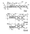
- the different embodiments of the product are illustrated by the Figures 2A, 2B, 3, 4A to 4G, 5A and 5B representing cross sections.
- the peripheral zone 2 of width l includes marking patterns 9. At the level of these marking patterns, the thickness of the product is reduced. The first fold is pressed towards the inside of the product. The fibers of the first fold 10 have been overwritten and to a lesser extent those of the second fold 11, thereby ensuring the connection of the two folds.
- the first fold 10 is embossed according to embossing patterns 12 thereby increasing the total thickness of the produced in this area.
- the narrower parts 13 of the reliefs of the motifs of embossing are oriented towards the inside of the folds in order to limit the loss of softness in these embossed areas.
- Figure 2B is a variant of the product shown in Figure 2A in which the marking patterns 109 of the peripheral zone 102 appear on the level of the second fold 111 which is pressed towards the inside of the product.
- the first fold 110 is also slightly depressed. It is the first fold 110 which includes the embossing patterns 112 in the central area 107.
- the product in the peripheral zone 202 of width l comprises patterns 214 which are both embossing patterns and marking patterns.
- the overall thickness E 1 of the product is greater in the peripheral zone compared to the thickness e 1 of the two folds simply superimposed without embossing or marking.
- the fold 210 is pressed towards the inside of the product, the thickness of the product e in this hollow part which corresponds to the connection of the two folds ensured by the marking, is reduced relative to at the thickness e 1 of the two folds simply superimposed without embossing or marking.
- the marking patterns are completely identical to the embossing patterns.
- the marking patterns can also be only partially identical to the embossing patterns.
- the peripheral zone may include additional patterns which will be embossing patterns alone.
- the central area 207 remains unchanged and only includes embossing patterns 212.
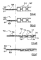
- FIG. 4A illustrates another embodiment of the product according to the invention.
- the peripheral zone includes marking and embossing patterns 314 similar to FIG. 3. But in the central zone, the two folds each include embossing patterns.
- the fold 310 comprises embossing patterns 312 and the fold 311 comprises embossing patterns 316.
- the embossing patterns 312 and 316 are identical for the two folds.
- the recessed portions of the embossing patterns of one ply being in the point-to-tip position with the recessed portions of the patterns of the other ply.
- the two folds in the central area are perfectly symmetrical on the cross section of the product.
- the overall thickness E 2 of the product in the central zone is greater here than the thickness E 1 of the product in the peripheral zone. In the case of FIG. 3, E 2 is substantially equal to E 1 .
- the embossing patterns 412 and 416 of each of the folds 410 and 411 are identical to those 312 and 316 of the product shown in FIG. 4A.
- the embossing patterns of the central zone can also be different between the two folds which will no longer be symmetrical in cross section.
- FIGS. 4C and 4D differ from the products represented in FIGS. 4A and 4B by their peripheral zone 502 and 602 which do not understands that a marking pattern 509 and 609, printed respectively mainly on the first fold 510, secondarily on the second fold 511 and mainly on the second fold 611 and secondarily on the first fold 610.
- the two folds are also symmetrical in the central sectional area transverse.
- the two folds can still be asymmetrical in cross section in the central area.
- the hollow parts of the embossing patterns 712 of the fold 710 can be position or nest in the raised parts of the 716 embossing patterns of the other fold 711, we then speak of "nested" position.
- the two folds may not be in contact over the entire deformed surface of the folds, as shown in FIG. 4E: the part 717 of fold 710 does not come into contact from part 718 of fold 711.
- Figure 4F illustrates a variant in which the second fold 811 is first pressed in at the level of the 809 marking patterns for the peripheral area 802.
- FIG. 4G illustrates a product according to the invention comprising three folds: two outer pleats 850 and 851 embossed and a central pleat 852 unembossed.
- the two folds 850 and 851 include embossing patterns 862 in tip-tip position.
- the three folds 850, 851 and 852 include marking patterns 879.
- FIG. 5A illustrates a product in which the peripheral zone 902 includes marking patterns such as those described for the product shown in the Figure 2A.
- the two folds 910 and 911 in the central area include 919 embossing patterns and are associated by these embossing patterns.
- the fold 910 in the peripheral zone, includes the patterns of marking 909.
- the products described above may include in their central area not only embossing patterns but also marking patterns forming a watermark, which constitute other decorations.
- the method according to the invention has the advantage of providing a product in format comprising a combination of marking patterns and embossing patterns, the area peripheral comprising at least marking patterns and the central zone, at less embossing patterns.
- This product has at least two folds, the patterns of marking and embossing being located on the same fold or on different folds.
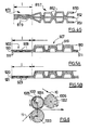
- FIG. 6 A first simple embodiment of the method according to the invention is illustrated by figure 6.
- the method consists of a first step, to emboss a first ply 10 of cellulose wadding between a first cylinder engraved in hard material 1001 and a first counter-cylinder 1002 here in deformable material, for example rubber so as to emboss the central zone products according to the invention at the first fold.
- a second step a second ply of cellulose wadding 11 is superimposed on the first embossed ply 10 and the two folds are marked together so as to be linked, between the first cylinder engraved in hard material 1001 and a second cylinder made of smooth hard material 1003 (i.e. a cylinder whose surface is not engraved).
- the first cylinder 1001 is engraved, among others, on surfaces corresponding to the peripheral zones 2 of the products in formats according to the invention.
- the two folds 10 and 11 in the peripheral zone of the formats, undergo a pressure necessary for the connection. This pressure is exerted by the system formed by the first engraved cylinder 1001 and the second smooth cylinder in hard material 1003. This principle is found in all the methods of the invention described below.
- the two folds at the end of this marking step are linked at least in peripheral zone 2.
- the products are then cut into formats.
- the product produced by this process is illustrated in Figure 2A.
- the device allowing the implementation of the above process is illustrated by the set of three cylinders shown in Figure 6.
- the first engraved cylinder 1001 is made of steel and has engraved areas 1004 on the surface corresponding to the embossing patterns 12 of the central zone 7 of the products in format. It also includes between the etched areas 1004, etched areas 1005 corresponding to the patterns of marking 9 of the peripheral zone 2 of the products in format.
- the counter-cylinder or receiving cylinder 1002 of the first engraved cylinder 1001 is made of deformable material, for example rubber, and includes zones hollowed out 1006 positioned opposite the engraved areas 1005 of the first engraved cylinder 1001 corresponding to the marking patterns 9 in the peripheral zone 2 products in formats.
- the second cylinder made of hard material 1003 is made of steel or other non-deformable material.
- the first cylinder engraved in hard material 1001 has two engraving levels: a first level for engraved areas 1004 corresponding to the embossing patterns 12 of the central zone 7 of the products in format and a second level for the engraved areas 1005 corresponding to the patterns of marking 9 of the peripheral zone 2 of the products in format.
- the first counter-cylinder 1002 made of deformable material, for example rubber, includes recessed areas 1006 into which the engraved areas are inserted marking 1005 of the first engraved cylinder 1001 when the two cylinders are applied one against the other during the embossing step. Note that these areas engraved 1005 are not applied directly against the recessed areas 1006.
- Figure 6C illustrates the heights of the engraved areas of the first cylinders engraved and second cylinder in smooth hard material and / or engraved devices according to the invention.
- Zone G corresponds to the surface of the cylinders intended for the embossing of the central zone of products in format and zone M corresponds to the surface of cylinders intended for marking the peripheral zone of products in format.
- the engraved areas of the cylinders have prominent or raised portions.
- the etching height, for example h 1 of a raised part is defined by the distance between the surface S of this raised part and the central axis of the cylinder in a direction perpendicular to the aforementioned surface.
- h 1 is the engraving height of the engraved area of the first engraved cylinder corresponding to the embossing patterns of the central area of the products in format.
- h 2 is the engraving height of the engraved area of the first engraved cylinder corresponding to the marking patterns of the peripheral area.
- h 3 is the engraving height of the unengraved or engraved area of the second hard or engraved cylinder corresponding to the central area of the product in format.
- And h 4 is the etching height of the unetched or etched area of the second cylinder corresponding to the peripheral area.
- FIG. 6D illustrates the heights of the different engraved zones 1004 and 1005 of the first engraved cylinder 1001 applied against the second cylinder of hard material 1003 of the device shown in FIG. 6.
- the raised parts of the engraving have a height h 1 .
- the raised parts of the engraving have a height h 2 .
- h 2 is strictly greater than h 1 .
- the heights h 3 and h 4 are equal.
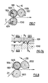
- FIG. 7 A variant of the device represented in FIG. 6 is illustrated by FIG. 7.
- the product obtained is illustrated in FIG. 2A.
- FIG. 7A illustrates the respective heights of the raised parts of the first engraved cylinder applied against the second hard cylinder of the device shown in figure 7.
- the first engraved cylinder 1001 comprises in its engraved zones 1004 raised parts having a height h 1 and in its engraved zones 1005, raised parts having a height h 2 .
- h 2 is greater than or equal to h 1 .
- the second steel cylinder 1050 comprises recessed zones 1051 thus creating a smooth hollow part having a height h 3 , and a smooth part having a height h 4 in the zone of the cylinder 1050 coming to be positioned opposite the raised parts of the engraved area 1005 of the first engraved cylinder 1001 corresponding to the marking patterns 9 of the peripheral area 2 of the products in format.
- the sum of the heights h 2 and h 4 is strictly greater than the sum of the heights h 1 and h 3 .
- the method consists in embossing the first ply of cotton wool of cellulose 210 between the first cylinder engraved in hard material 1001 and the first counter-cylinder of deformable material 2002.
- This first fold 210 is embossed in the central area 207 of the product in format and also in the peripheral area 202 of the product in format.
- the second fold 211 is then attached to the first embossed fold 210 and the two folds are marked between the first cylinder engraved in hard material 1001 and the second smooth cylinder made of hard material 1003.
- the two folds are marked according to all or part of the embossing pattern of the first fold in the peripheral area of the product in format.
- FIG 3. A product produced by this process is illustrated in Figure 3. Indeed, one can see that in the peripheral zone 202 of the product in format, the patterns 214 are at the both embossing patterns and marking patterns.
- the second hard cylinder 1003 here is perfectly smooth as well as the 2002 counter-cylinder made of deformable material.
- FIG. 6D illustrates the heights h 1 and h 2 of the raised portions respectively of the engraved zones 1004 and 1005 of the first engraved cylinder 1001 applied against the second smooth hard cylinder 1003.
- the device shown in Figure 9 is a variant of that shown in figure 8. It is distinguished by the second hard cylinder 4001, made of steel which includes hollowed out areas 4006 which are positioned opposite the engraved areas 3004 of the first engraved cylinder 3001, corresponding to the central zone 207 of the products in format.
- FIG. 9A represents the configuration of the first engraved cylinder 3001 and second hard cylinder 4001 applied one against the other during the step of marking in partial transverse section along line IX-IX of FIG. 9.
- h ' 2 is less than or equal to h' 1
- h ' 3 is strictly less than h' 4
- the sum of the heights h ' 2 and h' 4 is strictly greater than the sum of the heights h ' 1 and h' 3 .
- the second hard cylinder 5001 can be engraved in the corresponding zones 5002 to the marking patterns 109 of the peripheral zone 102 of the products in format.
- the 5050 cylinder includes smooth recessed areas 5055 positioned opposite engraved areas 5002 of the second hard cylinder engraved 5001.
- the cylinder 5001, between the engraved zones 5002, comprises hollowed out zones 5056.
- FIG. 10A shows the height of the raised parts of the zones: h “ 1 for the engraved zone 5057 and h" 2 for the plane zone 5055 of the first engraved cylinder 5050, h “ 3 for the plane and smooth zone 5056 and h” 4 for the engraved area 5002 of the second hard cylinder engraved 5001.
- h " 2 is strictly less than h" 1 and h " 3 strictly less than h” 4 .
- the sum of the heights h “ 2 and h” 4 is strictly greater than the sum of the heights h " 1 and h” 3 .
- the first engraved cylinder 5050 will have the function of embossing and participate in the marking in conjunction with the second hard engraved cylinder 5002 which will have the only function is to mark.
- FIG. 2B The resulting product is illustrated in Figure 2B.
- the peripheral zone 102 of the product in format it is the second fold 111 which is pressed by the cylinder 5001 and to a lesser extent the first superimposed fold 110.
- FIG. 11 Another embodiment of the method according to the invention is illustrated by the figure 11.
- This process consists of embossing the first ply of cellulose wadding 310 between the first cylinder engraved in 1001 steel and the smooth 2002 counter-cylinder in material deformable, at least in a central zone 307 of the products in format, emboss the second fold 311 between the second cylinder engraved in hard material 6000 and a second counter-cylinder of deformable material 7000, at least in the central zone 307 of the products in format, then superimpose the two folds separately embossed and mark them between the first engraved cylinder 1001 and the second hard cylinder 6000, and finally cut out products in formats.
- the first engraved cylinder 1001 is similar to the cylinder shown in the figure 6A comprising two engraving levels.
- a first level of engraving corresponds to the engraved area 1004 for the embossing patterns 312 of the central area 307 of the products in format.
- the second level of engraving corresponds to the engraved area 1005 intended for marking patterns 314 which, here, are also embossing patterns of the peripheral area of products in format.
- the second engraved cylinder 6000 includes engraved zones 6001 for the embossing of the patterns of the central area 307 of the second fold 311 and of the flat areas not engraved 6002 corresponding to the peripheral zone 302 of the products in format.
- zones 1004 and 6001 of cylinders 1001 and 6000 can be identical or different. Cylinders 1001 and 6000 must be synchronized from so that we can superimpose the two embossed folds in the "tip-tip" position or offset of the "nested" type.
- FIG. 4A A product obtained by a tip-tip process is illustrated in Figure 4A.
- the product is produced by engraved cylinders or embossers in tip-tip position.
- FIGS. 11A to 11D show different possibilities for distributing the engraving heights on the two engraved cylinders of the device according to FIG. 11.
- the first engraved cylinder 1001 comprises engraved zones 1004, the raised parts of which have a height h 1 corresponding to the embossing patterns 312 of the central zone 307 of the products in format for the first fold, and engraved zones 1005, the raised parts of which have a height h 2 corresponding to the embossing and marking patterns 314 of the peripheral zone 302 of the products in formats.
- the second engraved cylinder 6000 comprises engraved zones 6001, the raised parts of which have a height h 3 corresponding to the embossing patterns 316 of the central zone 307 of the products in format for the second fold 311 and non-engraved zones 6002, smooth, having a height h 4 and corresponding to the peripheral zone 302 of the products in format.
- the sum of the heights h2 and h4 is strictly greater than the sum of the heights h 1 and h 3 .
- h 4 when h 2 is equal to h 1 , h 4 is strictly greater than h 3 and when h 2 is strictly greater than h 1 , h 4 is greater than or equal to h 3 .
- h 4 when h 2 is equal to h 1 , h 4 is strictly greater than h 3 and when h 2 is strictly less than h 1 , h 4 is greater than or equal to h 3 .
- h 4 when h 2 is equal to h 1 , h 4 is strictly less than h 3 and when h 2 is strictly greater than h 1 , h 4 is less than or equal to h 3 .
- FIG. 11D illustrates the "nested" position for the association of the two embossed folds by means of the engraved cylinders 1001 and 6000.
- h 2 is less than or equal to h 1 and h 4 is less than or equal to h 3 .
- the sum of the heights h 2 and h 4 is strictly greater than h 1 and strictly greater than h 3 .
- the first fold 510 is embossed between the first cylinder engraved in hard material 1001 and the first counter-cylinder 1002 in material deformable in the central area of format products.
- the second fold 511 is also embossed between the second cylinder engraved in hard material 6000 and the second counter-cylinder 7000 of deformable material in the central area of the products in format.
- the two folds 510 and 511 are then superimposed and marked between the first cylinder engraved 1001 and the second cylinder engraved 6000 in the area peripheral 502 products in format. Finally, the products are cut into formats.
- the first engraved cylinder of the device shown in Figure 12 includes engraved areas 1004 corresponding to the embossing patterns 512 of the central area 507 products in formats and engraved areas 1005 corresponding to the patterns of marking 509 of the peripheral zone 502 of the products in formats.
- the counter-cylinder 1002 made of deformable material includes recessed areas 1006 positioned at the level of the engraved areas 1005 of the first cylinder engraved 1001 corresponding to the marking patterns 509 of the peripheral zone 502 products in format, when the two cylinders are applied against each other.
- the first fold 510 is not embossed in the peripheral zone 502.
- the second engraved cylinder 6000 includes engraved zones 6001 corresponding to the embossing patterns 512 of the central zone 507 of the products in format and unetched areas 6002 corresponding to the peripheral area 502 of the products in format. These smooth non-etched areas 6002 are positioned opposite engraved areas 1005 of the first engraved cylinder 1001, which are intended for marking of the peripheral zone 502 of the products in formats.
- the second counter-cylinder 7000 made of deformable material also includes recessed areas 7006 which are positioned at the level of the smooth areas not engraved 6002 of the second cylinder engraved 6000 when the two cylinders are applied one against the other so that the second fold is not embossed either in the area peripheral 502 products in formats.
- the engraved cylinder 1001 may be of the type shown in FIG. 6A, and includes two levels of engraving.
- the counter cylinders 1002 and 7000 are of the type of that shown in FIG. 6B on which zones of deformable material 1006 or 7006 have been hollowed out.
- FIGS. 11A to 11D show the distributions between the different heights h 1 , h 2 , h 3 and h 4 of the parts in relief of the engraved areas.
- FIG. 13 is a variant in which a third smooth or embossed fold 852 is introduced in the marking step between the two embossed folds 850 and 851.
- the third fold 852 could also be introduced at the marking stage of the processes illustrated in Figures 11 and 12.
- Another subject of the invention is to carry out simultaneously the embossing and marking stages.
- this method consists in simultaneously embossing the first and second folds 910 and 911 between the first engraved cylinder 1001 and a counter-cylinder At least 8000 in a central 907 area of the format, mark simultaneously with the embossing step the first and second folds 910 and 911 between the first cylinder engraved 1001 and the second counter-cylinder 8000 comprising smooth hard surfaces 8002 in zones corresponding to the 909 marking patterns in the zone peripheral 902 and deformable zones 8003 corresponding to the engraved zones of embossing 1004.
- the first and second folds 910 and 911 are superimposed and pass between a cylinder engraved in hard material of steel 1001 comprising engraved areas 1004 corresponding to the embossing patterns 919 of the central zone 907 for products in formats and an 8000 counter-cylinder comprising non-etched surface areas 8003 of deformable material such as rubber, positioned opposite the engraved areas 1004 of the first engraved cylinder 1001 when the two cylinders 1001 and 8000 are applied against each other for the setting of the process.
- the two folds 910 and 911 are thus embossed together and associated in the central zone 907 products in formats.
- smooth non-etched surface areas 8003 can be replaced by engraved areas of hard material.
- the engraved cylinder 1001 includes engraved areas 1005 corresponding to the marking patterns 909 of the area device 902 format products.
- the 8000 cylinder has hard zones smooth not engraved 8006.
- the cylinder 1001 can be engraved on two levels like the engraved cylinder shown in Figure 6A.
- the counter-cylinder 8000 shown in FIG. 14A is made of steel or any similar hard material. It includes hollowed out or hollow areas that have been filled with 8003 inserts of deformable material such as rubber, ensuring thus the smooth deformable counterpart for the embossing step.
- the remaining surfaces 8006 of the counter-cylinder 8000 are hard and smooth and participate in tagging.
- the counter-cylinder 9000 which includes engraved areas 9005 corresponding to the marking patterns 929 of the peripheral area of products in format.
- the engraved cylinder 6000 includes him non-etched hard zones 6002 positioned opposite the etched zones 9005 of cylinder 9000 when the two cylinders are applied against each other for the implementation of the process.
- the cylinder 9000 also includes inserts 9006 made of material deformable ensuring the smooth counterpart for the embossing step.
- all of the engraved steel cylinders described above for the devices according to the invention can be made of other materials having similar hardnesses and similar properties.
- the counter cylinders made of any deformable material have resilience characteristics desired.
- cylinders made of hard material, engraved or smooth may include treads located at the ends of the cylinders, which allow limit the shocks linked to variations in the surfaces of the patterns.
Abstract
Description
L'invention concerne un produit en papier absorbant à usage sanitaire et domestique. Elle vise plus particulièrement des produits découpés ou prédécoupés en formats tels que des mouchoirs en papier, des serviettes de table en papier jetables, ou des produits similaires. Ces produits comprennent au moins deux plis ou feuilles d'ouate de cellulose, superposés et associés par tout moyen connu.The invention relates to a paper towel product for sanitary use and domesticated. It relates more particularly to products cut or precut in formats such as tissues, disposable paper napkins, or similar products. These products include at least two folds or sheets of cellulose wadding, superimposed and combined by any known means.
Les termes "marquage" et "gaufrage" mentionnés dans la description qui suit, ont les significations suivantes.The terms "marking" and "embossing" mentioned in the description which follows, have the following meanings.
Le "marquage" consiste à comprimer certaines parties d'un pli ou d'une feuille constituée de plusieurs plis d'ouate de cellulose, en formant des zones compactées et en réduisant significativement l'épaisseur du pli ou de la feuille dans ces zones sans former de relief correspondant sur la face opposée. Lorsque plusieurs plis sont marqués ensemble, en particulier deux plis, ces derniers sont associés et liés."Marking" consists of compressing certain parts of a fold or sheet consisting of several plies of cellulose wadding, forming compacted areas and by significantly reducing the thickness of the fold or sheet in these areas without form corresponding relief on the opposite face. When multiple folds are marked together, in particular two folds, the latter are associated and linked.
Le produit marqué comprend des zones comprimées d'épaisseur réduite formant des motifs de marquage sur le produit.The marked product includes compressed areas of reduced thickness forming marking patterns on the product.
Le "gaufrage" consiste à créer sur un pli d'ouate de cellulose ou plusieurs plis superposés, des reliefs sur une première face avec des dépressions correspondantes sur la face opposée des plis, en augmentant l'épaisseur du ou des plis superposés. Les reliefs et dépressions ainsi obtenus forment des motifs de gaufrage en surface des produits en papier. Cette technique peut également permettre d'obtenir une association des plis.The "embossing" consists in creating on a ply of cellulose wadding or several plies superimposed, reliefs on a first face with corresponding depressions on the opposite side of the folds, increasing the thickness of the overlapped fold (s). The reliefs and depressions thus obtained form embossing patterns on the surface of the paper products. This technique can also provide a association of folds.
La plupart des serviettes en papier présentes sur le marché, ont des bordures liées par gaufrage avec une augmentation de l'épaisseur dans les zones périphériques assemblées.Most paper towels on the market have borders linked by embossing with an increase in thickness in the peripheral areas assemblies.
Parmi les serviettes de table apparues plus récemment sur le marché, certaines présentent une liaison mécanique des plis localisée au niveau des bords et obtenue exclusivement par marquage.Among the napkins appeared more recently on the market, some have a mechanical connection of the folds located at the edges and obtained exclusively by marking.
Un des procédés de marquage consiste à faire passer deux plis d'ouate de cellulose entre un cylindre gravé en acier et un contre-cylindre lisse en acier, le cylindre gravé comportant des zones en relief, le plus souvent sous forme de picots sur une partie de sa surface correspondant aux bords de la serviette. La pression exercée par les cylindres est suffisante pour lier les plis. Le produit découpé obtenu comporte sur une de ses faces, des bordures avec des parties comprimées ou surfaces compactées dans lesquelles l'épaisseur est significativement réduite. Il n'y a pas de relief correspondant sur l'autre face du produit. Ces produits se distinguent par une absence de surépaisseur. Ils ont une zone centrale plate, sans surépaisseur au centre. Ils ne présentent pas de gonflant et n'ont pas de "main", propriétés cependant recherchées pour des produits destinés à l'essuyage de la peau.One of the marking methods consists in passing two plies of cotton wool cellulose between an engraved steel cylinder and a smooth steel counter-cylinder, the engraved cylinder with raised areas, most often in the form of pins on a part of its surface corresponding to the edges of the towel. Pressure exerted by the cylinders is sufficient to bind the folds. The cut product obtained has on one of its faces, borders with compressed parts or surfaces compacted in which the thickness is significantly reduced. There is no corresponding relief on the other side of the product. These products are distinguished by a absence of additional thickness. They have a flat central area, with no allowance in the center. They do not have bulking and do not have a "hand", properties however sought after for products intended for wiping the skin.
Une autre technique de marquage pour lier des bordures de mouchoirs est décrite dans la demande WO-A-95/27429.Another marking technique for tying handkerchief borders is described in application WO-A-95/27429.
Elle consiste à marquer chacune des faces du produit au moyen de deux cylindres gravés comportant chacun des parties en relief sous forme de picots, les picots d'un cylindre étant en position pointe-pointe par rapport aux picots de l'autre cylindre. Les deux plis sont ainsi liés sous l'action du marquage et la pression exercée par les cylindres, par des points. Les deux faces externes du produit sont enfoncées au niveau des points vers l'intérieur de la feuille, chaque point sur une face correspondant à un autre point sur l'autre face.It consists of marking each side of the product with two engraved cylinders each comprising raised parts in the form of pins, the pins of a cylinder being in point-point position relative to the pins of the other cylinder. The two folds are thus linked under the action of the marking and the pressure exerted by cylinders, by points. The two external faces of the product are pressed in level of points towards the inside of the sheet, each point on one side corresponding to another point on the other side.
Ce procédé nécessite une très grande précision et un niveau de contrôle élevé.This process requires very high precision and a high level of control.
Les produits obtenus présentent les mêmes inconvénients que ceux décrits pour le procédé de marquage classique décrit plus haut, à savoir qu'ils sont plats dans la zone centrale.The products obtained have the same drawbacks as those described for the conventional marking process described above, namely that they are flat in the central area.
La demande de brevet européen A-0 674 990 décrit des serviettes de table en papier qui sont gaufrées. Le gaufrage permet de créer sur une partie de la surface de chacun des plis formant le produit, des motifs en relief avec des dépressions correspondantes sur la face opposée des plis. De ce fait, le produit qui est gaufré, augmente en épaisseur.European patent application A-0 674 990 describes napkins in paper that are embossed. The embossing allows to create on a part of the surface of each of the folds forming the product, relief patterns with depressions on the opposite side of the folds. Therefore, the product which is embossed, increases in thickness.
Dans l'art antérieur cité dans la demande EP-A-0 674 990, trois possibilités sont présentées : le gaufrage uniquement des bordures de la serviette, le gaufrage de la surface de la serviette dans sa totalité et le gaufrage de bords avec d'autres points de gaufrage sélectionnés dans la partie centrale entre les bords.In the prior art cited in application EP-A-0 674 990, three possibilities are presented: the embossing only of the edges of the napkin, the embossing of the entire surface of the napkin and the embossing of edges with other dots of embossing selected in the central part between the edges.
Pour la première possibilité, les serviettes une fois pliées en quatre présentent une certaine dissymétrie. Lorsqu'elles sont empilées et emballées, les paquets ont tendance à se déformer. De plus, les serviettes ont un toucher désagréable dans les zones de bordures du fait du relief asymétrique du gaufrage. For the first possibility, the towels once folded in four present a certain asymmetry. When stacked and wrapped, the packages have tendency to warp. In addition, the towels have an unpleasant touch in the border areas due to the asymmetrical embossing relief.
Pour la seconde possibilité, il est difficile d'atteindre des pressions élevées pour gaufrer toute la surface de la serviette si bien que la liaison mécanique des plis est moins bonne sans compter la perte de douceur entraínée par le gaufrage de toute la surface.For the second possibility, it is difficult to reach high pressures to emboss the entire surface of the towel so that the mechanical connection of the folds is less good without counting the loss of softness caused by the embossing of the whole area.
La troisième possibilité est un compromis entre les deux autres, avec une répartition sélective des points de gaufrage dans la partie centrale de la serviette.The third possibility is a compromise between the other two, with a selective distribution of the embossing points in the central part of the napkin.
Mais les inconvénients sont une combinaison de ceux évoquées dans les deux possibilités précédentes.But the disadvantages are a combination of those mentioned in the two previous possibilities.
La solution proposée par cette demande antérieure EP-A-0 674 990 pour éviter ces différents inconvénients, est une serviette ayant un motif de gaufrage fonctionnel comprenant un gaufrage de bordure et un motif de gaufrage formant décor situé sur un des bords pliés opposé au gaufrage de bordure. Une surface d'essuyage non gaufrée subsiste. En fait, les parties de la serviette qui vont former les bords intérieurs pliés, sont gaufrées afin que le produit une fois plié ait une épaisseur relativement constante, ce qui permet d'éviter les problèmes de déformation des paquets de serviettes empilées.The solution proposed by this previous application EP-A-0 674 990 for avoid these various disadvantages, is a napkin having an embossing pattern functional including border embossing and embossing pattern forming decoration located on one of the folded edges opposite the border embossing. A surface waffle wiping remains. In fact, the parts of the towel that will form the folded inner edges, are embossed so that the product when folded has a thickness relatively constant, which avoids the problems of deformation of stacked towel packs.
Une autre technique d'association des bords d'un produit découpé tel qu'un mouchoir, est révélée par la demande WO-A-94/12343. Elle comprend la combinaison d'un gaufrage et d'un collage, l'association des plis étant assurée par le collage des bords. Mais le procédé pour fabriquer de tels produits est délicat dès lors qu'un adhésif est utilisé. Et l'adhésif rigidifie le produit.Another technique for combining the edges of a cut product such as handkerchief, is disclosed by application WO-A-94/12343. It includes the combination of embossing and bonding, the association of folds being ensured by the bonding of edges. However, the process for manufacturing such products is delicate therefore that an adhesive is used. And the adhesive stiffens the product.
L'invention a pour but de pallier l'ensemble des inconvénients cités précédemment, en fournissant un produit en papier absorbant découpé ou prédécoupé en format, comprenant au moins deux plis bien associés, ce produit étant souple, présentant du gonflant et une bonne main dans sa zone centrale, tout en restant agréable au toucher. En effet, on recherche à obtenir des produits ayant une plus grande épaisseur perçue par rapport à la plupart des produits classiques relativement plats dans leur zone centrale. Cette épaisseur perçue peut notamment découler de la différence d'épaisseur entre les bordures ou zone périphérique de la serviette et la zone centrale.The invention aims to overcome all of the drawbacks mentioned previously, by providing a paper towel product cut or precut in format, comprising at least two well associated folds, this product being flexible, with bulk and a good hand in its central area, while remaining pleasant to the touch. Indeed, we seek to obtain products with a higher large perceived thickness compared to most conventional products relatively dishes in their central area. This perceived thickness may in particular result from the difference in thickness between the edges or peripheral area of the towel and the central area.
L'invention a également pour but de fournir des procédés simples de fabrication du produit selon l'invention permettant de combiner différentes natures et types de motifs. The invention also aims to provide simple methods of manufacture of the product according to the invention making it possible to combine different natures and types of patterns.
L'invention a encore pour but de fournir des dispositifs permettant la mise en oeuvre de ces procédés.Another object of the invention is to provide devices allowing the implementation work of these processes.
Pour rappel, les termes "marquage" et "gaufrage" utilisés dans la description de l'invention qui suit, ont également les significations suivantes.As a reminder, the terms "marking" and "embossing" used in the description of the invention which follows, also have the following meanings.
Le "marquage" consiste à comprimer certaines parties d'un pli ou de plusieurs plis d'ouate de cellulose, en formant des zones compactées et en réduisant significativement l'épaisseur du pli ou des plis dans ces zones sans former de relief correspondant sur la face opposée. Lorsque plusieurs plis sont marqués ensemble, en particulier deux plis, ces derniers sont associés et liés dans les zones compactées ou marquées, ce qui est le cas dans la présente invention."Marking" consists in compressing certain parts of a fold or several folds of cellulose wadding, forming compacted areas and reducing significantly the thickness of the fold or folds in these areas without forming any relief corresponding on the opposite side. When several folds are marked together, in particular two folds, these are associated and linked in the compacted areas or marked, which is the case in the present invention.
Le produit marqué comprend des zones comprimées d'épaisseur réduite formant des motifs de marquage sur le produit.The marked product includes compressed areas of reduced thickness forming marking patterns on the product.
L'invention englobe plusieurs procédés de marquage et exclut le marquage associé à un collage.The invention encompasses several methods of labeling and excludes labeling associated with a collage.
Le procédé de marquage de bordure le plus classique consiste à marquer et lier au moins deux plis en faisant passer les deux plis entre un cylindre gravé en matériau dur du type en acier dont les motifs de gravure sont constitués de picots et un contre-cylindre lisse, également en matériau dur, du type en acier et en appliquant une pression suffisante.The most common border marking process is to mark and link at least two folds by passing the two folds between a cylinder engraved in material hard of the steel type whose etching patterns consist of pins and a counter-cylinder smooth, also of hard material, of the steel type and applying a sufficient pressure.
Un autre procédé consiste à marquer un motif formant filigrane sur un produit en papier absorbant, en déformant sous contrainte le produit par au moins un passage entre un cylindre gravé dur et non déformable dont les motifs de gravure sont de type linéaire et un cylindre récepteur d'une dureté d'au moins 40 Shore D.Another method is to mark a watermark pattern on a product. absorbent paper, deforming the product under stress by at least one pass between a hard, non-deformable engraved cylinder whose etching patterns are of the type linear and a receiving cylinder with a hardness of at least 40 Shore D.
Le produit ainsi marqué a la particularité d'avoir des surfaces marquées lisses, brillantes et translucides formant des filigranes, les surfaces non marquées étant mates. Ce produit et ce procédé sont décrits plus en détails dans la demande WO-A-97/20107.The product thus marked has the particularity of having smooth marked surfaces, shiny and translucent forming watermarks, the unmarked surfaces being mates. This product and this process are described in more detail in the application. WO-A-97/20107.
Le "gaufrage" consiste à créer sur un pli d'ouate de cellulose ou plusieurs plis superposés, des reliefs sur une première face avec des dépressions correspondantes sur la face opposée des plis, en augmentant l'épaisseur du ou des plis superposés. Les reliefs et dépressions ainsi obtenus forment des motifs de gaufrage en surface des produits en papier. The "embossing" consists in creating on a ply of cellulose wadding or several plies superimposed, reliefs on a first face with corresponding depressions on the opposite side of the folds, increasing the thickness of the overlapped fold (s). The reliefs and depressions thus obtained form embossing patterns on the surface of the paper products.
Différentes techniques de gaufrage sont possibles. L'invention exclut toutefois, en ce qui concerne le gaufrage de plusieurs plis, un gaufrage combiné à un collage.Different embossing techniques are possible. The invention excludes however, with respect to embossing multiple plies, embossing combined with a collage.
Un des procédés de gaufrage consiste à faire passer un ou plusieurs plis entre un cylindre gravé en matériau dur comprenant des motifs de gravure mâles et une contrepartie gravée en matériau dur comprenant des motifs de gravure femelles correspondants.One of the embossing methods consists in passing one or more folds between a cylinder engraved in hard material comprising male engraving patterns and a counterpart engraved in hard material including female engraving patterns correspondents.
Un autre procédé consiste à faire passer un ou plusieurs plis entre un cylindre en matériau dur par exemple en acier, gravé, comportant des motifs de gravure mâles et un contre-cylindre en matériau déformable tel que papier ou caoutchouc. Le contre-cylindre se déforme en épousant les motifs de gravure mâles du cylindre gravé. Le résultat obtenu est voisin de celui obtenu par le premier procédé décrit ci-dessus.Another method is to pass one or more folds between a cylinder of hard material, for example steel, engraved, having male engraving patterns and a counter-cylinder made of deformable material such as paper or rubber. The counter-cylinder deforms by matching the male engraving patterns of the engraved cylinder. The result obtained is close to that obtained by the first method described above.
D'autres procédés de gaufrage existent combinant plusieurs cylindres gravés en matériau dur non déformable avec des cylindres en matériau déformable non gravés. Plusieurs plis peuvent ainsi être gaufrés puis associés.Other embossing processes exist combining several engraved cylinders in non-deformable hard material with cylinders in non-deformable material engraved. Several folds can thus be embossed and then associated.
Suivant la position des cylindres gravés l'un par rapport à l'autre, les parties en relief des motifs de gaufrage d'un pli peuvent venir se positionner en face des parties en relief des motifs de gaufrage d'un autre pli ; cette position est qualifiée de pointe-pointe. Elles peuvent aussi être décalées par rapport aux parties en relief des motifs de gaufrage de l'autre pli ; on parle alors de position "nested" : une partie en creux d'un motif de gaufrage d'un pli venant se placer dans une partie en relief du motif de gaufrage de l'autre pli.Depending on the position of the engraved cylinders with respect to each other, the parts in relief of the embossing patterns of a fold can be positioned opposite the parts embossed embossing patterns of another fold; this position is qualified as tip-tip. They can also be offset from the raised parts of the patterns. embossing of the other fold; we then speak of a "nested" position: a hollow part of a embossing pattern of a fold placed in an embossed part of the pattern embossing of the other fold.
Tout type de gaufrage peut être envisagé dans la présente invention.Any type of embossing can be envisaged in the present invention.
De préférence, le procédé de gaufrage utilisé consiste à faire passer un ou plusieurs plis entre un cylindre gaufreur ou cylindre gravé en matériau dur, du type en acier, comprenant des motifs de gravure et un contre-cylindre ou cylindre récepteur lisse, en matériau déformable tel que caoutchouc.Preferably, the embossing process used consists in passing one or more several folds between an embossing cylinder or cylinder engraved in hard material, of the type steel, including engraving patterns and a counter cylinder or receiving cylinder smooth, in deformable material such as rubber.
En général, chacun des plis est gaufré séparément puis les deux plis gaufrés sont superposés. Les deux plis peuvent aussi être gaufrés ensemble et être associés partiellement par le gaufrage.In general, each of the folds is embossed separately and then the two embossed folds are superimposed. The two folds can also be embossed together and can be combined partially by embossing.
Dans un des modes de réalisation de l'invention décrit plus loin, le marquage des plis peut s'effectuer sur deux plis superposés dont l'un est déjà gaufré et comporte des motifs de gaufrage. Les motifs de marquage sont dans ce cas en partie ou totalement identiques aux motifs de gaufrage. In one of the embodiments of the invention described below, the marking folds can be made on two superimposed folds, one of which is already embossed and has embossing patterns. The marking reasons are in this case partly or completely identical to the embossing patterns.
L'invention a pour objet un produit en papier absorbant tel qu'une serviette ou un mouchoir comprenant au moins deux plis d'ouate de cellulose superposés et associés, découpés ou prédécoupés au format souhaité et liés entre eux le long d'au moins une partie d'une zone périphérique.The subject of the invention is a product made of absorbent paper such as a towel or a handkerchief comprising at least two folds of superimposed cellulose wadding and associated, cut or precut to the desired format and linked together along at least minus part of a peripheral area.
Selon une caractéristique essentielle de l'invention, les plis sont liés le long de ladite partie par des motifs de marquage sans collage et au moins un pli comprend des motifs de gaufrage dans la zone centrale.According to an essential characteristic of the invention, the folds are linked along said part by marking patterns without gluing and at least one fold comprises embossing patterns in the central area.
Selon une autre caractéristique de l'invention, les deux plis comprennent des motifs de gaufrage identiques ou différents dans la zone centrale.According to another characteristic of the invention, the two folds include identical or different embossing patterns in the central area.
Selon une caractéristique avantageuse de l'invention, dans la zone périphérique, au moins un des plis ne comprend que des motifs de marquage.According to an advantageous characteristic of the invention, in the area peripheral, at least one of the folds comprises only marking patterns.
Selon une autre caractéristique avantageuse de l'invention, dans la zone périphérique, au moins un des plis comprend des motifs de marquage en partie ou totalement identiques aux motifs de gaufrage.According to another advantageous characteristic of the invention, in the area peripheral, at least one of the folds includes patterns of marking in part or completely identical to the embossing patterns.
Selon encore une caractéristique de l'invention, les motifs de marquage dans la zone périphérique forment des filigranes.According to another characteristic of the invention, the marking patterns in the peripheral zone form watermarks.
Selon une caractéristique préférée de l'invention, la zone centrale d'un pli comprend un décor formé par la combinaison de parties gaufrées et de parties non gaufrées.According to a preferred characteristic of the invention, the central area of a fold includes a decoration formed by the combination of embossed parts and non-embossed parts embossed.
L'invention a aussi pour objet un procédé de fabrication du produit selon l'invention, caractérisé en ce qu'il consiste à :
- a1) gaufrer un premier pli d'ouate de cellulose entre un premier cylindre gravé et un premier contre-cylindre au moins dans une zone centrale du format,
- b) superposer un second pli et lier les deux plis le long d'une zone périphérique du format par marquage entre le premier cylindre gravé ou non gravé dans les zones correspondant à la zone périphérique et un second cylindre en matériau dur, respectivement non gravé ou gravé dans les zones correspondant à la zone périphérique, de manière à obtenir une liaison des plis, et
- c) découper ou prédécouper en formats.
- a1) embossing a first ply of cellulose wadding between a first engraved cylinder and a first counter-cylinder at least in a central area of the format,
- b) superimpose a second ply and link the two plies along a peripheral zone of the format by marking between the first cylinder engraved or not engraved in the zones corresponding to the peripheral zone and a second cylinder made of hard material, respectively not engraved or engraved in the zones corresponding to the peripheral zone, so as to obtain a connection of the folds, and
- c) cut or precut into formats.
Selon une autre caractéristique essentielle de l'invention, le procédé comprend entre l'étape a1) et l'étape b), une étape supplémentaire a2) consistant à gaufrer le second pli entre le second cylindre en matériau dur, gravé au moins dans une zone correspondant à la zone centrale du format, et un second contre-cylindre. According to another essential characteristic of the invention, the method comprises between step a1) and step b), an additional step a2) consisting of embossing the second fold between the second cylinder of hard material, engraved at least in one area corresponding to the central area of the format, and a second counter-cylinder.
L'invention a également pour objet un procédé, caractérisé en ce qu'il consiste
à :
L'invention a encore pour objet des dispositifs pour la mise en oeuvre des procédés selon l'invention.The invention also relates to devices for the implementation of methods according to the invention.
Selon une caractéristique essentielle de l'invention, un premier dispositif comprend :
- un premier groupe de cylindres comprenant un premier cylindre gravé en matériau dur et un premier contre-cylindre en matériau déformable, le premier cylindre gravé comprenant une première zone gravée correspondant aux motifs de gaufrage de la zone centrale du format pour le premier pli et présentant une hauteur de gravure h1 et une seconde zone gravée correspondant aux motifs de marquage de la zone périphérique du format et présentant une hauteur de gravure h2, et,
- un second groupe de cylindres comprenant un second cylindre gravé en matériau dur et un second contre-cylindre en matériau déformable, le second cylindre gravé comprenant une première zone gravée correspondant aux motifs de gaufrage de la zone centrale du format pour le second pli et présentant une hauteur de gravure h3 et une seconde zone non gravée correspondant à la zone périphérique du format et présentant une hauteur h4, la somme des hauteurs h2 et h4 étant supérieure à la somme des hauteurs h1 et h3.
- a first group of cylinders comprising a first cylinder engraved in hard material and a first counter-cylinder in deformable material, the first engraved cylinder comprising a first engraved zone corresponding to the embossing patterns of the central zone of the format for the first fold and having a engraving height h 1 and a second engraved zone corresponding to the marking patterns of the peripheral zone of the format and having an engraving height h 2 , and,
- a second group of cylinders comprising a second cylinder engraved in hard material and a second counter-cylinder in deformable material, the second engraved cylinder comprising a first engraved zone corresponding to the embossing patterns of the central zone of the format for the second fold and having a etching height h 3 and a second non-etched area corresponding to the peripheral area of the format and having a height h 4 , the sum of the heights h 2 and h 4 being greater than the sum of the heights h 1 and h 3 .
Selon une caractéristique essentielle de l'invention, un autre dispositif comprend :
- un premier groupe de cylindres comprenant un premier cylindre gravé en matériau dur et un contre-cylindre en matériau déformable, le premier cylindre gravé comprenant une première zone gravée correspondant aux motifs de gaufrage de la zone centrale du format pour le premier pli et présentant une hauteur de gravure h1 ou h'1 et une seconde zone gravée correspondant aux motifs de marquage de la zone périphérique du format et présentant une hauteur de gravure h2 ou h'2, et
- un second cylindre en matériau dur comprenant une première zone lisse correspondant à la zone centrale du format, présentant une hauteur de gravure h3 ou h'3 et une seconde zone plane correspondant en tout ou partie à la zone périphérique et présentant une hauteur de gravure h4 ou h'4, cette seconde zone étant destinée à se positionner en face des zones gravées du premier cylindre gravé correspondant aux motifs de marquage, la somme des hauteurs h2 ou h'2 et respectivement h4 ou h'4 étant strictement supérieure à la somme des hauteurs h1 ou h'1 et respectivement h3 ou h'3.
- a first group of cylinders comprising a first cylinder engraved in hard material and a counter-cylinder in deformable material, the first engraved cylinder comprising a first engraved zone corresponding to the embossing patterns of the central zone of the format for the first fold and having a height etching h 1 or h ' 1 and a second etched area corresponding to the marking patterns of the peripheral area of the format and having an etching height h 2 or h' 2 , and
- a second cylinder of hard material comprising a first smooth zone corresponding to the central zone of the format, having an engraving height h 3 or h ' 3 and a second planar zone corresponding in whole or in part to the peripheral zone and having an engraving height h 4 or h ' 4 , this second zone being intended to be positioned opposite the engraved zones of the first engraved cylinder corresponding to the marking patterns, the sum of the heights h 2 or h' 2 and respectively h 4 or h ' 4 being strictly greater than the sum of the heights h 1 or h ' 1 and respectively h 3 or h' 3 .
Selon une caractéristique essentielle d'un autre dispositif selon l'invention, ce dernier comprend :
- un premier groupe de cylindres comprenant un premier cylindre gravé en matériau dur et un premier contre-cylindre en matériau déformable, le premier cylindre gravé comprenant une première zone gravée correspondant aux motifs de gaufrage de la zone centrale du format pour le premier pli et présentant une hauteur de gravure h"1 et une seconde zone lisse correspondant à la zone périphérique du format présentant une hauteur de gravure h"2, h"2 étant strictement inférieure à h"1,
- un second cylindre gravé en matériau dur comprenant une première zone lisse correspondant à la zone centrale du format présentant une hauteur de gravure h"3 et une seconde zone gravée correspondant aux motifs de marquage de la zone périphérique du format et présentant une hauteur de gravure h"4, h"3 étant strictement inférieure à h"4 et la somme des hauteurs h"2 et h"4 étant strictement supérieure à la somme des hauteurs h"1 et h"3.
- a first group of cylinders comprising a first cylinder engraved in hard material and a first counter-cylinder in deformable material, the first engraved cylinder comprising a first engraved zone corresponding to the embossing patterns of the central zone of the format for the first fold and having a engraving height h " 1 and a second smooth zone corresponding to the peripheral zone of the format having an engraving height h" 2 , h " 2 being strictly less than h" 1 ,
- a second cylinder engraved in hard material comprising a first smooth zone corresponding to the central zone of the format having an engraving height h " 3 and a second engraved zone corresponding to the marking patterns of the peripheral zone of the format and having an engraving height h " 4 , h" 3 being strictly less than h " 4 and the sum of the heights h" 2 and h " 4 being strictly greater than the sum of the heights h" 1 and h " 3 .
Selon une caractéristique essentielle d'encore un autre dispositif selon l'invention, ce dernier comprend :
- un premier cylindre gravé en matériau dur comprenant des zones gravées correspondant aux motifs de gaufrage de la zone centrale du format et des zones gravées ou non gravées correspondant aux motifs de marquage de la zone périphérique du format, et
- un premier contre-cylindre comprenant des zones de surface non gravées en matériau déformable ou des zones de surface gravées en matériau dur destinées respectivement à se positionner en face des zones gravées du premier cylindre gravé correspondant aux motifs de gaufrage de la zone centrale du format, et des zones de surfaces dures non gravées ou gravées destinées à se positionner en face des zones gravées ou non gravées du premier cylindre dans des zones correspondant aux motifs de marquage de la zone périphérique du format,
- a first cylinder engraved in hard material comprising engraved zones corresponding to the embossing patterns of the central zone of the format and engraved or non-engraved zones corresponding to the marking patterns of the peripheral zone of the format, and
- a first counter-cylinder comprising non-etched surface areas of deformable material or etched surface areas of hard material intended respectively to be positioned opposite the etched areas of the first etched cylinder corresponding to the embossing patterns of the central area of the format, and areas of hard surfaces not engraved or engraved intended to be positioned opposite the engraved or non-engraved zones of the first cylinder in zones corresponding to the marking patterns of the peripheral zone of the format,
D'autres détails et avantages de l'invention apparaítront plus clairement à la lecture détaillée de la description qui suit en référence aux dessins dans lesquels :
- la figure 1 est une représentation schématique d'une vue de dessus d'un produit en format découpé selon l'invention ;
- la figure 2A est une coupe partielle schématique selon la ligne II-II du produit selon la figure 1 ;
- la figure 2B est une variante du produit représenté à la figure 2A ;
- les figures 3, 4A à 4G, 5A et 5B représentent chacune, une coupe partielle schématique d'autres modes de réalisation du produit selon l'invention ;
- la figure 6 illustre un mode de réalisation du procédé selon l'invention et un dispositif pour sa mise en oeuvre ;
- la figure 6A représente le premier cylindre en matériau dur gravé du dispositif suivant la figure 6 ;
- la figure 6B représente le contre-cylindre en matériau déformable du dispositif suivant la figure 6 ;
- la figure 6C est une représentation schématique générale d'une vue partielle du premier cylindre gravé en matériau dur appliqué contre le second cylindre gravé en matériau dur illustrant les hauteurs des zones gravées ;
- la figure 6D est une représentation schématique d'une coupe partielle transversale du premier cylindre gravé appliqué contre le second cylindre en matériau dur lisse suivant la ligne VI-VI de la figure 6 ;
- la figure 7 représente une alternative du dispositif représenté à la figure 6 ;
- la figure 7A est une représentation schématique d'une coupe partielle transversale du premier cylindre gravé appliqué contre le second cylindre dur suivant la ligne VII-VII de la figure 7 ;
- la figure 8 illustre un autre mode de réalisation du procédé selon l'invention et le dispositif correspondant permettant sa mise en oeuvre ;
- la figure 9 représente une alternative du dispositif représenté à la figure 8 ;
- la figure 9A est une représentation schématique d'une coupe partielle transversale du premier cylindre gravé appliqué contre le second cylindre dur suivant la ligne IX-IX de la figure 9 ;
- la figure 10 représente une autre alternative du dispositif représenté à la figure 8 ;
- la figure 10A est une représentation schématique d'une coupe partielle transversale du premier cylindre gravé appliqué contre le second cylindre dur gravé suivant la ligne X-X de la figure 10 ;
- la figure 11 illustre un autre mode de réalisation du procédé selon l'invention ainsi qu'un dispositif pour sa mise en oeuvre ;
- les figures 11A à 11D sont des représentations schématiques de coupes partielles transversales du premier cylindre gravé appliqué contre le second cylindre gravé suivant 1a ligne XI-XI de la figure 11 ;
- la figure 12 représente une variante du dispositif représenté à la figure 11 ;
- la figure 13 illustre une variante du procédé représenté en figure 11, dans laquelle un troisième pli est introduit ;
- la figure 14 représente encore un autre mode de réalisation du procédé selon l'invention et du dispositif pour sa mise en oeuvre ;
- la figure 14A représente le premier cylindre gravé du dispositif représenté en figure 14 ; et
- la figure 15 représente une variante du dispositif représenté en figure 14.
- Figure 1 is a schematic representation of a top view of a product in cut format according to the invention;
- Figure 2A is a schematic partial section along the line II-II of the product according to Figure 1;
- Figure 2B is a variant of the product shown in Figure 2A;
- Figures 3, 4A to 4G, 5A and 5B each show a schematic partial section of other embodiments of the product according to the invention;
- FIG. 6 illustrates an embodiment of the method according to the invention and a device for its implementation;
- FIG. 6A represents the first cylinder of hard material etched from the device according to FIG. 6;
- FIG. 6B represents the counter-cylinder made of deformable material of the device according to FIG. 6;
- FIG. 6C is a general schematic representation of a partial view of the first cylinder engraved in hard material applied against the second cylinder engraved in hard material illustrating the heights of the engraved areas;
- Figure 6D is a schematic representation of a partial cross section of the first engraved cylinder applied against the second cylinder of smooth hard material along the line VI-VI of Figure 6;
- Figure 7 shows an alternative of the device shown in Figure 6;
- Figure 7A is a schematic representation of a partial cross section of the first engraved cylinder applied against the second hard cylinder along line VII-VII of Figure 7;
- FIG. 8 illustrates another embodiment of the method according to the invention and the corresponding device allowing its implementation;
- Figure 9 shows an alternative of the device shown in Figure 8;
- Figure 9A is a schematic representation of a partial cross section of the first engraved cylinder applied against the second hard cylinder along the line IX-IX of Figure 9;
- Figure 10 shows another alternative of the device shown in Figure 8;
- FIG. 10A is a schematic representation of a partial transverse section of the first engraved cylinder applied against the second hard cylinder engraved along the line XX of FIG. 10;
- FIG. 11 illustrates another embodiment of the method according to the invention as well as a device for its implementation;
- FIGS. 11A to 11D are schematic representations of partial transverse sections of the first engraved cylinder applied against the second engraved cylinder along the line XI-XI of FIG. 11;
- Figure 12 shows a variant of the device shown in Figure 11;
- FIG. 13 illustrates a variant of the method represented in FIG. 11, in which a third fold is introduced;
- FIG. 14 represents yet another embodiment of the method according to the invention and of the device for its implementation;
- Figure 14A shows the first engraved cylinder of the device shown in Figure 14; and
- FIG. 15 represents a variant of the device represented in FIG. 14.
Le produit selon l'invention est un produit en papier absorbant, plus précisément en ouate de cellulose. Il est découpé en format par exemple carré ou rectangulaire.The product according to the invention is a paper towel product, more precisely in cellulose wadding. It is cut in format, for example square or rectangular.
Ce produit est un mouchoir ou une serviette de table en papier ou tout produit similaire.This product is a tissue or paper napkin or any product similar.
Il comprend au moins deux plis d'ouate de cellulose superposés et associés. Le produit qui est décrit ci-après et illustré par les figures 1 à 5B, comprend deux plis d'ouate de cellulose.It comprises at least two plies of cellulose wadding superimposed and associated. The product which is described below and illustrated by FIGS. 1 to 5B, comprises two folds cellulose wadding.
La figure 1 représente schématiquement, vu de dessus, un produit découpé 1 :
une serviette de table ou un mouchoir, ici de forme carrée. Il comprend une zone
périphérique 2 formant une bande d'une largeur déterminée ℓ, le long des bords 3, 4,
5 et 6 du produit 1, et une zone centrale 7 entourée par la zone périphérique 2. FIG. 1 schematically represents, seen from above, a cut product 1:
a napkin or handkerchief, here square. It includes an area
peripheral 2 forming a strip of a determined width ℓ, along the
Les deux plis sont liés le long de cette zone périphérique 2 de largeur ℓ par des
motifs de marquage sans collage. Suivant la technique de marquage utilisée, le motif
de marquage peut être constitué de formes simples ou complexes. Il peut comprendre
de petites surfaces en forme de disques, losanges ou autres, réalisées par un marquage
de type classique. Il peut aussi être constitué d'un ensemble de lignes, traits, courbes
formant un dessin et définissant un motif décoratif lorsqu'on utilise la technique de
marquage formant un filigrane telle que décrite dans la demande WO 97/20107.The two folds are linked along this
La figure 1 illustre un mode préféré de réalisation du produit comprenant un
motif de gaufrage réparti sur toute la surface de cette zone centrale sous la forme de
petites surfaces représentées ici par des points. De préférence, la zone centrale
comprend également des parties non gaufrées 8 formant elles-mêmes des décors et
créant des zones plus douces au contact de la peau, pour les produits destinés à
l'essuyage de la peau en tant que serviette ou mouchoir. Suivant un autre mode de
réalisation préféré, les motifs de gaufrage de la zone centrale forment un décor et
alternent avec des zones non gaufrées. Les zones non gaufrées sont réparties dans la
zone centrale du format de forme carrée de manière à être symétriques de par et
d'autre des médianes du format. De ce fait, les produits une fois pliés en quatre
présente une certaine symétrie.FIG. 1 illustrates a preferred embodiment of the product comprising a
embossing pattern distributed over the entire surface of this central area in the form of
small areas represented here by dots. Preferably, the central area
also includes
Dans le produit selon l'invention, les plis sont liés mécaniquement dans 1a zone périphérique et comportent une zone centrale, apportant du gonflant et de la main au produit. Les différents modes de réalisation du produit, sont illustrés par les figures 2A, 2B, 3, 4A à 4G, 5A et 5B représentant des coupes transversales.In the product according to the invention, the folds are mechanically linked in 1a peripheral zone and include a central zone, providing bulking and hand to the product. The different embodiments of the product are illustrated by the Figures 2A, 2B, 3, 4A to 4G, 5A and 5B representing cross sections.
Les éléments correspondant à chaque figure portent la même référence augmentée chaque fois d'une centaine.The elements corresponding to each figure have the same reference increased each time by a hundred.
En référence à la figure 2A, la zone périphérique 2 de largeur ℓ, comprend des
motifs de marquage 9. Au niveau de ces motifs de marquage, l'épaisseur du produit
est réduite. Le premier pli est enfoncé vers l'intérieur du produit. Les fibres du
premier pli 10 ont été écrasées et dans une moindre mesure celles du second pli 11,
assurant de ce fait la liaison des deux plis. Dans la zone centrale 7, le premier pli 10
est gaufré suivant des motifs de gaufrage 12 augmentant ainsi l'épaisseur totale du
produit dans cette zone. Les parties les plus étroites 13 des reliefs des motifs de
gaufrage sont orientées vers l'intérieur des plis afin de limiter la perte de douceur
dans ces zones gaufrées. With reference to FIG. 2A, the
La figure 2B est une variante du produit représenté à la figure 2A dans
laquelle les motifs de marquage 109 de la zone périphérique 102 apparaissent au
niveau du second pli 111 qui est enfoncé vers l'intérieur du produit. Le premier pli
110 est quant à lui également légèrement enfoncé. C'est le premier pli 110 qui
comprend les motifs de gaufrage 112 dans la zone centrale 107.Figure 2B is a variant of the product shown in Figure 2A in
which the marking
Sur la figure 3, le produit dans la zone périphérique 202 de largeur ℓ
comprend des motifs 214 qui sont à la fois des motifs de gaufrage et des motifs de
marquage. L'épaisseur globale E1 du produit est plus grande dans la zone
périphérique par rapport à l'épaisseur e1 des deux plis simplement superposés sans
gaufrage ni marquage. Dans la partie en creux 215 du motif 214, le pli 210 est
enfoncé vers l'intérieur du produit, l'épaisseur du produit e dans cette partie en creux
qui correspond à la liaison des deux plis assurée par le marquage, est réduite par
rapport à l'épaisseur e1 des deux plis simplement superposés sans gaufrage ni
marquage. Sur cette figure 3, dans la zone périphérique 202, les motifs de marquage
sont totalement identiques aux motifs de gaufrage. Suivant un autre mode de
réalisation non représenté, les motifs de marquage peuvent également être seulement
en partie identiques aux motifs de gaufrage. En d'autres termes, la zone périphérique
peut comprendre des motifs supplémentaires qui seront des motifs de gaufrage seuls.
La zone centrale 207 reste inchangée et comprend uniquement des motifs de gaufrage
212.In FIG. 3, the product in the
La figure 4A illustre un autre mode de réalisation du produit selon l'invention.
La zone périphérique comprend des motifs de marquage et gaufrage 314
similairement à la figure 3. Mais dans la zone centrale, les deux plis comprennent
chacun des motifs de gaufrage. Le pli 310 comprend des motifs de gaufrage 312 et le
pli 311 comprend des motifs de gaufrage 316. Sur cette figure 4A, les motifs de
gaufrage 312 et 316 sont identiques pour les deux plis. Les parties en creux des
motifs de gaufrage d'un pli étant en position pointe-pointe avec les parties en creux
des motifs de l'autre pli. Les deux plis dans la zone centrale sont parfaitement
symétriques sur la coupe transversale du produit. Sur 1a figure 4A, l'épaisseur globale
E2 du produit dans la zone centrale est supérieure ici à l'épaisseur E1 du produit dans
la zone périphérique. Dans le cas de la figure 3, E2 est sensiblement égale à E1.FIG. 4A illustrates another embodiment of the product according to the invention. The peripheral zone includes marking and
Sur la figure 4B, à l'inverse de la figure 4A, dans la zone périphérique 402,
c'est le second pli 411 qui comprend des motifs de marquage identiques aux motifs
de gaufrage 414, ces motifs de marquage étant imprimés principalement sur le second
pli 411 et secondairement sur le premier pli 410.In FIG. 4B, in contrast to FIG. 4A, in the
Dans la zone centrale 407, les motifs de gaufrage 412 et 416 de chacun des
plis 410 et 411 sont identiques à ceux 312 et 316 du produit représenté à la figure 4A.In the
Suivant un autre mode de réalisation non représenté, les motifs de gaufrage de la zone centrale peuvent aussi être différents entre les deux plis qui ne seront plus symétriques en coupe transversale.According to another embodiment not shown, the embossing patterns of the central zone can also be different between the two folds which will no longer be symmetrical in cross section.
Les produits représentés aux figures 4C et 4D diffèrent des produits
représentés aux figures 4A et 4B de par leur zone périphérique 502 et 602 qui ne
comprend qu'un motif de marquage 509 et 609, imprimé respectivement
principalement sur le premier pli 510, secondairement sur le second pli 511 et
principalement sur le second pli 611 et secondairement sur le premier pli 610. Sur ces
figures, les deux plis sont aussi symétriques dans la zone centrale en coupe
transversale.The products shown in Figures 4C and 4D differ from the products
represented in FIGS. 4A and 4B by their
Les deux plis peuvent encore être dissymétriques en coupe transversale dans la zone centrale.The two folds can still be asymmetrical in cross section in the central area.
Un tel produit est représenté à la figure 4E. Par exemple, dans la zone
centrale 707, les parties en creux des motifs de gaufrage 712 du pli 710 peuvent se
positionner ou s'imbriquer dans les parties en relief des motifs de gaufrage 716 de
l'autre pli 711, on parle alors de position "nested".Such a product is shown in Figure 4E. For example, in the area
central 707, the hollow parts of the
Les deux plis peuvent ne pas être en contact sur toute la surface déformée des
plis, tel que le représente la figure 4E : la partie 717 du pli 710 ne vient pas en contact
de la partie 718 du pli 711.The two folds may not be in contact over the entire deformed surface of the
folds, as shown in FIG. 4E: the
Dans cette représentation, pour les motifs de marquage 709 de la zone
périphérique 702, c'est le premier pli 710 qui est d'abord enfoncé. La figure 4F
illustre une variante dans laquelle le second pli 811 est d'abord enfoncé au niveau des
motifs de marquage 809 pour la zone périphérique 802.In this representation, for the 709 marking patterns of the area
peripheral 702, it is the
La figure 4G illustre un produit selon l'invention comprenant trois plis : deux
plis extérieurs 850 et 851 gaufrés et un pli central 852 non gaufré. Dans la zone
centrale 857, les deux plis 850 et 851 comprennent des motifs de gaufrage 862 en
position pointe-pointe. Dans la zone périphérique 872 de largeur ℓ, les trois plis 850,
851 et 852 comprennent des motifs de marquage 879.FIG. 4G illustrates a product according to the invention comprising three folds: two
La figure 5A illustre un produit dans lequel la zone périphérique 902
comprend des motifs de marquage tels que ceux décrits pour le produit représenté à la
figure 2A. Pour ce mode de réalisation, les deux plis 910 et 911 dans la zone centrale,
comprennent des motifs de gaufrage 919 et sont associés par ces motifs de gaufrage.
Sur cette figure 5A, dans la zone périphérique, le pli 910 comprend les motifs de
marquage 909. D'une autre manière, il est également possible de marquer le pli 921
tel que représenté en figure 5B. Les motifs de marquage 929 apparaissent en surface
du pli 921.FIG. 5A illustrates a product in which the
Les produits décrits précédemment peuvent comporter dans leur zone centrale non seulement des motifs de gaufrage mais également des motifs de marquage formant filigrane, qui constituent d'autres décors.The products described above may include in their central area not only embossing patterns but also marking patterns forming a watermark, which constitute other decorations.
Le procédé selon l'invention a l'avantage de fournir un produit en format comprenant une combinaison de motifs de marquage et de motifs de gaufrage, la zone périphérique comprenant au moins des motifs de marquage et la zone centrale, au moins des motifs de gaufrage. Ce produit comprend au moins deux plis, les motifs de marquage et de gaufrage étant situés sur le même pli ou sur des plis différents.The method according to the invention has the advantage of providing a product in format comprising a combination of marking patterns and embossing patterns, the area peripheral comprising at least marking patterns and the central zone, at less embossing patterns. This product has at least two folds, the patterns of marking and embossing being located on the same fold or on different folds.
Les exemples qui suivent illustrent le procédé selon l'invention. A un certain mode de réalisation du procédé, on rattachera différents dispositifs pour la mise en oeuvre du procédé dans ce mode de réalisation déterminé.The examples which follow illustrate the process according to the invention. At a certain embodiment of the method, various devices will be attached for the implementation work of the method in this specific embodiment.
Un premier mode de réalisation simple du procédé selon l'invention est illustré par la figure 6.A first simple embodiment of the method according to the invention is illustrated by figure 6.
Suivant le schéma représenté à la figure 6, le procédé consiste dans une
première étape, à gaufrer un premier pli 10 d'ouate de cellulose entre un premier
cylindre gravé en matériau dur 1001 et un premier contre-cylindre 1002 ici en
matériau déformable par exemple en caoutchouc de manière à gaufrer 1a zone centrale
des produits selon l'invention au niveau du premier pli. Dans une seconde étape, un
second pli d'ouate de cellulose 11 est superposé au premier pli gaufré 10 et les deux
plis sont marqués ensemble de manière à être liés, entre le premier cylindre gravé en
matériau dur 1001 et un second cylindre en matériau dur lisse 1003 (c'est-à-dire un
cylindre dont la surface n'est pas gravée). Le premier cylindre 1001 est gravé, entre-autres,
sur des surfaces correspondant aux zones périphériques 2 des produits en
formats selon l'invention. Les deux plis 10 et 11, dans la zone périphérique des
formats, subissent une pression nécessaire à la liaison. Cette pression est exercée par
le système formé du premier cylindre gravé 1001 et du second cylindre lisse en
matériau dur 1003. Ce principe se retrouve dans tous les procédés de l'invention
décrits ci-après. Les deux plis à l'issue de cette étape de marquage sont liés au moins
dans la zone périphérique 2. Les produits sont ensuite découpés en formats. Le
produit fabriqué par ce procédé est illustré par la figure 2A.According to the diagram shown in Figure 6, the method consists of a
first step, to emboss a
Le dispositif permettant la mise en oeuvre du procédé ci-dessus est illustré par
l'ensemble des trois cylindres représentés sur la figure 6. Le premier cylindre gravé
1001 est en acier et comprend en surface des zones gravées 1004 correspondant aux
motifs de gaufrage 12 de la zone centrale 7 des produits en format. Il comprend aussi
entre les zones gravées 1004, des zones gravées 1005 correspondant aux motifs de
marquage 9 de la zone périphérique 2 des produits en format.The device allowing the implementation of the above process is illustrated by
the set of three cylinders shown in Figure 6. The first
Sur cette figure et toutes les figures suivantes en coupe illustrant les procédés
et les dispositifs de l'invention, les zones gravées correspondant aux motifs de
marquage sont illustrées par la présence de deux points ![]()
![]()
Le contre-cylindre ou cylindre récepteur 1002 du premier cylindre gravé 1001
est en matériau déformable par exemple en caoutchouc et comprend des zones
évidées 1006 venant se positionner en face des zones gravées 1005 du premier
cylindre gravé 1001 correspondant aux motifs de marquage 9 de la zone périphérique
2 des produits en formats. Le second cylindre en matériau dur 1003 est en acier ou
autre matériau non déformable.The counter-cylinder or receiving
En référence à la figure 6A, le premier cylindre gravé en matériau dur 1001
comporte deux niveaux de gravure : un premier niveau pour les zones gravées 1004
correspondant aux motifs de gaufrage 12 de la zone centrale 7 des produits en format
et un second niveau pour les zones gravées 1005 correspondant aux motifs de
marquage 9 de la zone périphérique 2 des produits en format. Suivant la figure 6B, le
premier contre-cylindre 1002 en matériau déformable par exemple en caoutchouc,
comprend des zones évidées 1006 dans lesquelles viennent s'insérer les zones gravées
de marquage 1005 du premier cylindre gravé 1001 lorsque les deux cylindres sont
appliqués l'un contre l'autre lors de l'étape de gaufrage. Il est à noter que ces zones
gravées 1005 ne sont pas appliquées directement contre les zones évidées 1006.With reference to FIG. 6A, the first cylinder engraved in
La figure 6C illustre les hauteurs des zones gravées des premiers cylindre gravé et second cylindre en matériau dur lisse et/ou gravé des dispositifs selon l'invention.Figure 6C illustrates the heights of the engraved areas of the first cylinders engraved and second cylinder in smooth hard material and / or engraved devices according to the invention.
La zone G correspond à la surface des cylindres destinée au gaufrage de la zone centrale des produits en format et la zone M correspond à la surface des cylindres destinée au marquage de la zone périphérique des produits en format. Zone G corresponds to the surface of the cylinders intended for the embossing of the central zone of products in format and zone M corresponds to the surface of cylinders intended for marking the peripheral zone of products in format.
Les zones gravées des cylindres présentent des parties proéminentes ou en relief. La hauteur de gravure, par exemple h1 d'une partie en relief est définie par la distance entre la surface S de cette partie en relief et l'axe central du cylindre suivant une direction perpendiculaire à la surface précitée.The engraved areas of the cylinders have prominent or raised portions. The etching height, for example h 1 of a raised part is defined by the distance between the surface S of this raised part and the central axis of the cylinder in a direction perpendicular to the aforementioned surface.
h1 est la hauteur de gravure de la zone gravée du premier cylindre gravé correspondant aux motifs de gaufrage de la zone centrale des produits en format.h 1 is the engraving height of the engraved area of the first engraved cylinder corresponding to the embossing patterns of the central area of the products in format.
h2 est la hauteur de gravure de la zone gravée du premier cylindre gravé correspondant aux motifs de marquage de la zone périphérique.h 2 is the engraving height of the engraved area of the first engraved cylinder corresponding to the marking patterns of the peripheral area.
h3 est la hauteur de gravure de la zone non gravée ou gravée du second cylindre dur ou gravé correspondant à la zone centrale du produit en format.h 3 is the engraving height of the unengraved or engraved area of the second hard or engraved cylinder corresponding to the central area of the product in format.
Et h4 est la hauteur de gravure de la zone non gravée ou gravée du second cylindre correspondant à la zone périphérique.And h 4 is the etching height of the unetched or etched area of the second cylinder corresponding to the peripheral area.
La figure 6D illustre les hauteurs des différentes zones gravées 1004 et 1005
du premier cylindre gravé 1001 appliqué contre le second cylindre en matériau dur
1003 du dispositif représenté en figure 6. Dans la zone gravée 1004 correspondant
aux motifs de gaufrage 12 de la zone centrale 7 des produits en format, les parties en
relief de la gravure ont une hauteur h1. Dans la zone gravée 1005 correspondant aux
motifs de marquage 9 de la zone périphérique 2 des produits en formats, les parties en
relief de la gravure ont une hauteur h2. h2 est strictement supérieure à h1. Les hauteurs
h3 et h4 sont égales.FIG. 6D illustrates the heights of the different
Une variante du dispositif représenté à la figure 6 est illustrée par la figure 7. Le produit obtenu est illustré par la figure 2A.A variant of the device represented in FIG. 6 is illustrated by FIG. 7. The product obtained is illustrated in FIG. 2A.
Le procédé est identique à celui décrit en référence à la figure 6. La différence
réside dans le second cylindre dur 1050 du dispositif qui comprend des zones lisses
évidées 1051 dans lesquelles viennent s'insérer les zones 1004 du premier cylindre
gravé. Ces dernières ne sont pas directement appliquées l'une contre l'autre.The process is identical to that described with reference to Figure 6. The difference
resides in the second
La figure 7A illustre les hauteurs respectives des parties en relief du premier cylindre gravé appliqué contre le second cylindre dur du dispositif représenté en figure 7.FIG. 7A illustrates the respective heights of the raised parts of the first engraved cylinder applied against the second hard cylinder of the device shown in figure 7.
Le premier cylindre gravé 1001 comprend dans ses zones gravées 1004 des
parties en relief ayant une hauteur h1 et dans ses zones gravées 1005, des parties en
relief ayant une hauteur h2. h2 est supérieure ou égale à h1. Le second cylindre 1050
en acier comprend des zones évidées 1051 créant ainsi une partie en creux lisse ayant
une hauteur h3, et une partie lisse ayant une hauteur h4 dans la zone du cylindre 1050
venant se positionner en face des parties en relief de la zone gravée 1005 du premier
cylindre gravé 1001 correspondant aux motifs de marquage 9 de la zone périphérique
2 des produits en format. La somme des hauteurs h2 et h4 est strictement supérieure à
la somme des hauteurs h1 et h3.The first
En référence à la figure 8, le procédé consiste à gaufrer le premier pli d'ouate
de cellulose 210 entre le premier cylindre gravé en matériau dur 1001 et le premier
contre-cylindre en matériau déformable 2002. Ce premier pli 210 est gaufré dans la
zone centrale 207 du produit en format et également dans la zone périphérique 202 du
produit en format. Le second pli 211 est ensuite rapporté sur le premier pli 210 gaufré
et les deux plis sont marqués entre le premier cylindre gravé en matériau dur 1001 et
le second cylindre lisse en matériau dur 1003. Dans cette étape de marquage, les deux
plis sont marqués suivant tout ou partie du motif de gaufrage du premier pli dans la
zone périphérique du produit en format.With reference to FIG. 8, the method consists in embossing the first ply of cotton wool
of
Un produit fabriqué par ce procédé est illustré par la figure 3. En effet, on peut
voir que dans la zone périphérique 202 du produit en format, les motifs 214 sont à la
fois des motifs de gaufrage et des motifs de marquage.A product produced by this process is illustrated in Figure 3. Indeed, one can
see that in the
Concernant le dispositif, le second cylindre dur 1003 ici est parfaitement lisse
ainsi que le contre-cylindre 2002 en matériau déformable.Regarding the device, the second
La figure 6D illustre les hauteurs h1 et h2 des parties en relief respectivement
des zones gravées 1004 et 1005 du premier cylindre gravé 1001 appliqué contre le
second cylindre dur lisse 1003.FIG. 6D illustrates the heights h 1 and h 2 of the raised portions respectively of the
Le dispositif représenté à la figure 9 est une variante de celui représenté à la
figure 8. Il se distingue par le second cylindre dur 4001, en acier qui comprend des
zones évidées 4006 qui viennent se positionner en face des zones gravées 3004 du
premier cylindre gravé 3001, correspondant à la zone centrale 207 des produits en
format.The device shown in Figure 9 is a variant of that shown in
figure 8. It is distinguished by the second
Les hauteurs h'1 et h'2 des parties en relief des zones gravées 3004 et 3005 du
premier cylindre gravé 3001 et les hauteurs h'3 et h'4 de la partie en relief du second
cylindre dur 4001 sont illustrées par la figure 9A qui représente la configuration des
premier cylindre gravé 3001 et second cylindre dur 4001 appliqués l'un contre l'autre
lors de l'étape de marquage en coupe partielle transversale suivant la ligne IX-IX de
la figure 9.The heights h ' 1 and h' 2 of the raised parts of the engraved
h'2 est inférieure ou égale à h'1, h'3 est strictement inférieure à h'4 et la somme des hauteurs h'2 et h'4 est strictement supérieure à la somme des hauteurs h'1 et h'3. h ' 2 is less than or equal to h' 1 , h ' 3 is strictly less than h' 4 and the sum of the heights h ' 2 and h' 4 is strictly greater than the sum of the heights h ' 1 and h' 3 .
Le produit issu d'une fabrication au moyen de ce dispositif peut être illustré par le produit représenté en figure 3.The product resulting from a manufacture using this device can be illustrated by the product shown in Figure 3.
A la différence du dispositif représenté à la figure 8 et en référence à la figure
10, le second cylindre dur 5001 peut être gravé dans les zones 5002 correspondant
aux motifs de marquage 109 de la zone périphérique 102 des produits en format. Le
cylindre 5050 comprend des zones lisses évidées 5055 venant se positionner en face
des zones gravées 5002 du second cylindre dur gravé 5001. Le cylindre 5001, entre
les zones gravées 5002, comporte des zones évidées 5056.Unlike the device shown in Figure 8 and with reference to the figure
10, the second
La figure 10A montre la hauteur des parties en relief des zones : h"1 pour la
zone gravée 5057 et h"2 pour la zone plane 5055 du premier cylindre gravé 5050, h"3
pour la zone plane et lisse 5056 et h"4 pour la zone gravée 5002 du second cylindre
dur gravé 5001. h"2 est strictement inférieure à h"1 et h"3 strictement inférieure à h"4.
La somme des hauteurs h"2 et h"4 est strictement supérieure à la somme des hauteurs
h"1 et h"3.FIG. 10A shows the height of the raised parts of the zones: h " 1 for the engraved
Ainsi, le premier cylindre gravé 5050 aura pour fonction de gaufrer et
participer au marquage en liaison avec le second cylindre gravé dur 5002 qui lui, aura
pour unique fonction celle de marquer.Thus, the first
Le produit en résultant est illustré par la figure 2B. Dans la zone périphérique
102 du produit en format, c'est le second pli 111 qui est enfoncé par le cylindre 5001
et dans une moindre mesure le premier pli superposé 110.The resulting product is illustrated in Figure 2B. In the
Un autre mode de réalisation du procédé selon l'invention est illustré par la
figure 11. Ce procédé consiste à gaufrer le premier pli d'ouate de cellulose 310 entre
le premier cylindre gravé en acier 1001 et le contre-cylindre 2002 lisse en matériau
déformable, au moins dans une zone centrale 307 des produits en format, gaufrer le
second pli 311 entre le second cylindre gravé en matériau dur 6000 et un second
contre-cylindre en matériau déformable 7000, au moins dans la zone centrale 307 des
produits en format, puis superposer les deux plis séparément gaufrés et les marquer
entre le premier cylindre gravé 1001 et le second cylindre dur 6000, et enfin découper
les produits en formats.Another embodiment of the method according to the invention is illustrated by the
figure 11. This process consists of embossing the first ply of
Le premier cylindre gravé 1001 est similaire au cylindre représenté en figure
6A comprenant deux niveaux de gravure. Un premier niveau de gravure correspond à
la zone gravée 1004 destinée aux motifs de gaufrage 312 de la zone centrale 307 des
produits en format. Le second niveau de gravure correspond à la zone gravée 1005
destinée aux motifs de marquage 314 qui, ici, sont aussi des motifs de gaufrage de la
zone périphérique des produits en format.The first
Le second cylindre gravé 6000 comprend des zones gravées 6001 pour le
gaufrage des motifs de la zone centrale 307 du second pli 311 et des zones planes non
gravées 6002 correspondant à la zone périphérique 302 des produits en format.The second
Les gravures des zones 1004 et 6001 des cylindres 1001 et 6000 peuvent être
identiques ou différentes. Les cylindres 1001 et 6000 doivent être synchronisés de
manière à ce que l'on puisse superposer les deux plis gaufrés en position "pointe-pointe"
ou décalée du type "nested".The engravings of
Un produit obtenu par un procédé pointe-pointe est illustré par la figure 4A. Dans ce mode de réalisation, le produit est réalisé par des cylindres gravés ou gaufreurs en position pointe-pointe.A product obtained by a tip-tip process is illustrated in Figure 4A. In this embodiment, the product is produced by engraved cylinders or embossers in tip-tip position.
Les figures 11A à 11D montrent différentes possibilités de répartition des hauteurs de gravure sur les deux cylindres gravés du dispositif suivant la figure 11.FIGS. 11A to 11D show different possibilities for distributing the engraving heights on the two engraved cylinders of the device according to FIG. 11.
Le premier cylindre gravé 1001 comprend des zones gravées 1004 dont les
parties en relief ont une hauteur h1 correspondant aux motifs de gaufrage 312 de la
zone centrale 307 des produits en format pour le premier pli et des zones gravées
1005 dont les parties en relief ont une hauteur h2 correspondant aux motifs de
gaufrage et marquage 314 de la zone périphérique 302 des produits en formats.The first
Le second cylindre gravé 6000 comprend des zones gravées 6001 dont les
parties en relief ont une hauteur h3 correspondant aux motifs de gaufrage 316 de la
zone centrale 307 des produits en format pour le second pli 311 et des zones non
gravées 6002, lisses, ayant une hauteur h4 et correspondant à la zone périphérique 302
des produits en format.The second
Pour toutes les possibilités illustrées par les figures 11A à 11C, la somme des hauteurs h2 et h4 est strictement supérieure à la somme des hauteurs h1 et h3.For all the possibilities illustrated by FIGS. 11A to 11C, the sum of the heights h2 and h4 is strictly greater than the sum of the heights h 1 and h 3 .
Suivant la figure 11A, lorsque h2 est égale à h1, h4 est strictement supérieure à h3 et lorsque h2 est strictement supérieure à h1, h4 est supérieure ou égale à h3.According to FIG. 11A, when h 2 is equal to h 1 , h 4 is strictly greater than h 3 and when h 2 is strictly greater than h 1 , h 4 is greater than or equal to h 3 .
Suivant la figure 11B, lorsque h2 est égale à h1, h4 est strictement supérieure à h3 et lorsque h2 est strictement inférieure à h1, h4 est supérieure ou égale à h3.According to FIG. 11B, when h 2 is equal to h 1 , h 4 is strictly greater than h 3 and when h 2 is strictly less than h 1 , h 4 is greater than or equal to h 3 .
Suivant la figure 11C, lorsque h2 est égale à h1, h4 est strictement inférieure à h3 et lorsque h2 est strictement supérieure à h1, h4 est inférieure ou égale à h3.According to FIG. 11C, when h 2 is equal to h 1 , h 4 is strictly less than h 3 and when h 2 is strictly greater than h 1 , h 4 is less than or equal to h 3 .
La figure 11D illustre la position "nested" pour l'association des deux plis
gaufrés au moyen des cylindres gravés 1001 et 6000. h2 est inférieure ou égale à h1 et
h4 est inférieure ou égale à h3. La somme des hauteurs h2 et h4 est strictement
supérieure à h1 et strictement supérieure à h3.FIG. 11D illustrates the "nested" position for the association of the two embossed folds by means of the
En inversant sur la figure 11, les cylindres 1001 et 6000, on obtient le produit
illustré par la figure 4B.By inverting in FIG. 11, the
Suivant la figure 12, le premier pli 510 est gaufré entre le premier cylindre
gravé en matériau dur 1001 et le premier contre-cylindre 1002 en matériau
déformable dans la zone centrale des produits en format. Parallèlement, le second pli
511 est également gaufré entre le second cylindre gravé en matériau dur 6000 et le
second contre-cylindre 7000 en matériau déformable dans la zone centrale des
produits en format. Les deux plis 510 et 511 sont ensuite superposés et marqués entre
le premier cylindre gravé 1001 et le second cylindre gravé 6000 dans la zone
périphérique 502 des produits en format. Enfin, les produits sont découpés en
formats.According to FIG. 12, the
Le premier cylindre gravé du dispositif représenté à la figure 12 comprend des
zones gravées 1004 correspondant aux motifs de gaufrage 512 de la zone centrale 507
des produits en formats et des zones gravées 1005 correspondant aux motifs de
marquage 509 de la zone périphérique 502 des produits en formats.The first engraved cylinder of the device shown in Figure 12 includes
engraved
Le contre-cylindre 1002 en matériau déformable comprend des zones évidées
1006 venant se positionner au niveau des zones gravées 1005 du premier cylindre
gravé 1001 correspondant aux motifs de marquage 509 de la zone périphérique 502
des produits en format, lorsque les deux cylindres sont appliqués l'un contre l'autre.The counter-cylinder 1002 made of deformable material includes recessed
Ainsi, le premier pli 510 n'est pas gaufré dans la zone périphérique 502.Thus, the
Le second cylindre gravé 6000 comprend des zones gravées 6001
correspondant aux motifs de gaufrage 512 de la zone centrale 507 des produits en
format et des zones non gravées 6002 correspondant à la zone périphérique 502 des
produits en format. Ces zones lisses non gravées 6002 viennent se positionner en face
des zones gravées 1005 du premier cylindre gravé 1001, qui sont destinées au
marquage de la zone périphérique 502 des produits en formats.The second
Le second contre-cylindre 7000 en matériau déformable comprend également
des zones évidées 7006 qui viennent se positionner au niveau des zones lisses non
gravées 6002 du second cylindre gravé 6000 lorsque les deux cylindres sont appliqués
l'un contre l'autre si bien que le second pli n'est pas gaufré non plus dans la zone
périphérique 502 des produits en formats. The second counter-cylinder 7000 made of deformable material also includes
recessed
Le cylindre gravé 1001 peut être du type de celui représenté en figure 6A, et
comprend deux niveaux de gravure. Les contre-cylindres 1002 et 7000 sont du type
de celui représenté en figure 6B sur lequel des zones de matériau déformable 1006 ou
7006 ont été évidées.The
Les deux cylindres gravés 1001 et 6000 en position de fonctionnement pour la
mise en oeuvre du procédé, peuvent être illustrés par les figures 11A à 11D qui
montrent les répartitions entre les différentes hauteurs h1, h2 , h3 et h4 des parties en
relief des zones gravées.The two
Des produits issus d'un tel procédé sont illustrés par les figures 4C et 4E.Products from such a process are illustrated in Figures 4C and 4E.
Lorsque les deux cylindres gravés 1001 et 6000 sont en position pointe-pointe,
le produit obtenu est représenté par la figure 4C. Et lorsque les deux cylindres gravés
1001 et 6000 sont en position "nested", le produit obtenu est représenté par la
figure 4E.When the two
En inversant sur la figure 12, les cylindres 1001 et 6000, on obtient un produit
illustré par les figures 4D et 4F correspondant respectivement à des cylindres gravés
6000 et 1001 appliqués l'un contre l'autre, en position "pointe-pointe" et en position
"nested".By inverting in FIG. 12, the
La figure 13 est une variante dans laquelle un troisième pli lisse ou gaufré 852
est introduit à l'étape de marquage entre les deux plis gaufrés 850 et 851. Le troisième
pli 852 pourrait aussi être introduit à l'étape de marquage des procédés illustrés aux
figures 11 et 12.FIG. 13 is a variant in which a third smooth or
Le produit obtenu suivant le procédé illustré par la figure 13, est représenté en figure 4G.The product obtained according to the process illustrated in FIG. 13, is represented by Figure 4G.
L'invention a pour objet un autre procédé permettant d'effectuer simultanément les étapes de gaufrage et marquage.Another subject of the invention is to carry out simultaneously the embossing and marking stages.
Suivant la figure 14, ce procédé consiste à gaufrer simultanément les premier
et second plis 910 et 911 entre le premier cylindre gravé 1001 et un contre-cylindre
8000 au moins dans une zone centrale 907 du format, marquer simultanément à
l'étape de gaufrage les premier et second plis 910 et 911 entre le premier cylindre
gravé 1001 et le second contre-cylindre 8000 comprenant des surfaces dures lisses
8002 dans des zones correspondant aux motifs de marquage 909 de la zone
périphérique 902 et des zones déformables 8003 correspondant aux zones gravées de
gaufrage 1004. According to FIG. 14, this method consists in simultaneously embossing the first
and
Plus précisément, en référence à la figure 14, les premier et second plis 910 et
911 sont superposés et passent entre un cylindre gravé en matériau dur en acier 1001
comprenant des zones gravées 1004 correspondant aux motifs de gaufrage 919 de la
zone centrale 907 des produits en formats et un contre-cylindre 8000 comprenant des
zones de surface non gravées 8003 en matériau déformable tel qu'en caoutchouc,
venant se positionner en face des zones gravées 1004 du premier cylindre gravé 1001
lorsque les deux cylindres 1001 et 8000 sont appliqués l'un contre l'autre pour la mise
en oeuvre du procédé. Les deux plis 910 et 911 sont ainsi gaufrés ensemble et associés
dans la zone centrale 907 des produits en formats. Suivant un autre mode de
réalisation non représenté, les zones de surface non gravées lisses 8003 peuvent être
remplacées par des zones gravées en matériau dur.More specifically, with reference to FIG. 14, the first and
Par ce même passage entre le cylindre gravé 1001 en acier et le contre-cylindre
8000, les deux plis sont marqués. Le cylindre gravé 1001 comprend des
zones gravées 1005 correspondant aux motifs de marquage 909 de la zone
périphérique 902 des produits en format. Le cylindre 8000 comprend des zones dures
lisses non gravées 8006. Le cylindre 1001 peut être gravé à deux niveaux comme le
cylindre gravé représenté en figure 6A.By this same passage between the
Par contre, le contre-cylindre 8000 représenté en figure 14A, est en acier ou tout matériau dur similaire. Il comprend des zones évidées ou creuses qui ont été comblées par des inserts 8003 en matériau déformable tel que le caoutchouc, assurant ainsi la contrepartie lisse déformable pour l'étape de gaufrage.On the other hand, the counter-cylinder 8000 shown in FIG. 14A, is made of steel or any similar hard material. It includes hollowed out or hollow areas that have been filled with 8003 inserts of deformable material such as rubber, ensuring thus the smooth deformable counterpart for the embossing step.
Les surfaces restantes 8006 du contre-cylindre 8000 sont dures et lisses et
participent au marquage.The remaining
Le produit ainsi obtenu est illustré par la figure 5A.The product thus obtained is illustrated in FIG. 5A.
Sur le dispositif suivant la figure 15, c'est le contre-cylindre 9000 qui
comprend des zones gravées 9005 correspondant aux motifs de marquage 929 de la
zone périphérique des produits en format. Le cylindre gravé 6000 comprend quant à
lui des zones dures non gravées 6002 venant se positionner en face des zones gravées
9005 du cylindre 9000 lorsque les deux cylindres sont appliquées l'un contre l'autre
pour la mise en oeuvre du procédé.On the device according to FIG. 15, it is the counter-cylinder 9000 which
includes engraved
Le cylindre 9000 comprend également des inserts 9006 en matériau
déformable assurant la contre-partie lisse pour l'étape de gaufrage.The
Le produit ainsi obtenu est illustré par la figure 5B. The product thus obtained is illustrated in FIG. 5B.
De manière générale, tous les cylindres gravés en acier décrits précédemment pour les dispositifs selon l'invention peuvent être réalisés dans d'autres matériaux présentant des duretés similaires et des propriétés similaires. De même, les contre-cylindres en tout matériau déformable présentent des caractéristiques de résilience souhaitées.In general, all of the engraved steel cylinders described above for the devices according to the invention can be made of other materials having similar hardnesses and similar properties. Likewise, the counter cylinders made of any deformable material have resilience characteristics desired.
Dans le cas des cylindres gravés, il est aussi possible d'utiliser des plaques gravées rapportées pour la partie des cylindres gravés réalisant le gaufrage de la zone centrale.In the case of engraved cylinders, it is also possible to use plates engraved reported for the part of the engraved cylinders embossing the area central.
De même, les cylindres en matériau dur, gravés ou lisses, peuvent comporter des bandes de roulement situées aux extrémités des cylindres, qui permettent de limiter les chocs liés aux variations des surfaces des motifs.Similarly, cylinders made of hard material, engraved or smooth, may include treads located at the ends of the cylinders, which allow limit the shocks linked to variations in the surfaces of the patterns.
Claims (20)
Priority Applications (5)
| Application Number | Priority Date | Filing Date | Title |
|---|---|---|---|
| EP00401192A EP1149552A1 (en) | 2000-04-28 | 2000-04-28 | Absorbent paper product such as serviettes or handkerchiefs, processes for the manufacture of such a product and devices for the carrying out of such processes |
| CA002344279A CA2344279C (en) | 2000-04-28 | 2001-04-18 | Absorbent paper product such as napkin or facial tissue, processes for the manufacture of such product and devices for the implementation of such processes |
| US09/839,407 US7026037B2 (en) | 2000-04-28 | 2001-04-23 | Absorbent paper product such as napkin or handkerchief, methods for manufacturing such a product, and apparatus implementing such methods |
| US11/128,386 US7670669B2 (en) | 2000-04-28 | 2005-05-13 | Absorbent paper product such as napkin or handkerchief, methods for manufacturing such a product, and apparatus implementing such methods |
| US11/237,829 US7513974B2 (en) | 2000-04-28 | 2005-09-29 | Absorbent paper product such as napkin or handkerchief, methods for manufacturing such a product, and apparatus implementing such methods |
Applications Claiming Priority (1)
| Application Number | Priority Date | Filing Date | Title |
|---|---|---|---|
| EP00401192A EP1149552A1 (en) | 2000-04-28 | 2000-04-28 | Absorbent paper product such as serviettes or handkerchiefs, processes for the manufacture of such a product and devices for the carrying out of such processes |
Publications (1)
| Publication Number | Publication Date |
|---|---|
| EP1149552A1 true EP1149552A1 (en) | 2001-10-31 |
Family
ID=8173663
Family Applications (1)
| Application Number | Title | Priority Date | Filing Date |
|---|---|---|---|
| EP00401192A Withdrawn EP1149552A1 (en) | 2000-04-28 | 2000-04-28 | Absorbent paper product such as serviettes or handkerchiefs, processes for the manufacture of such a product and devices for the carrying out of such processes |
Country Status (3)
| Country | Link |
|---|---|
| US (3) | US7026037B2 (en) |
| EP (1) | EP1149552A1 (en) |
| CA (1) | CA2344279C (en) |
Cited By (6)
| Publication number | Priority date | Publication date | Assignee | Title |
|---|---|---|---|---|
| WO2003057989A1 (en) * | 2001-12-31 | 2003-07-17 | Kimberly-Clark Worldwide, Inc. | Multiple ply paper wiping product having a soft side and a textured side |
| FR2895934A1 (en) * | 2006-01-12 | 2007-07-13 | Georgia Pacific France Soc En | HYBRID SHEET OF ABSORBENT PAPER, ROLL OF PAPER MADE FROM THIS SHEET |
| WO2009060353A1 (en) * | 2007-11-05 | 2009-05-14 | The Procter & Gamble Company | Textured multi-ply sanitary paper product having optimized emboss patterns |
| US7699959B2 (en) | 2000-11-14 | 2010-04-20 | Kimberly-Clark Worldwide, Inc. | Enhanced multi-ply tissue products |
| EP2228212A2 (en) * | 2009-03-13 | 2010-09-15 | Chan Li Machinery Co., Ltd. | Multiply thin paper sheet having press-to-bond structure |
| EP1319748B2 (en) † | 2001-12-12 | 2010-12-01 | Georgia-Pacific France | Multiply sheet of absorbent paper |
Families Citing this family (20)
| Publication number | Priority date | Publication date | Assignee | Title |
|---|---|---|---|---|
| EP1149552A1 (en) * | 2000-04-28 | 2001-10-31 | Georgia-Pacific France | Absorbent paper product such as serviettes or handkerchiefs, processes for the manufacture of such a product and devices for the carrying out of such processes |
| US7799169B2 (en) | 2004-09-01 | 2010-09-21 | Georgia-Pacific Consumer Products Lp | Multi-ply paper product with moisture strike through resistance and method of making the same |
| US8034215B2 (en) * | 2004-11-29 | 2011-10-11 | The Procter & Gamble Company | Patterned fibrous structures |
| ITFI20050033A1 (en) * | 2005-03-01 | 2006-09-02 | Perini Fabio Spa | EMBOSSING ROLLER, EMBEDDING DEVICE INCLUDING THE ROLLER AND ITEM OF PAPER-MADE MATERIAL MADE WITH THIS EMBOSSING DEVICE |
| EP1845193A1 (en) * | 2006-04-14 | 2007-10-17 | Georgia-Pacific France | Multi-ply absorbent sheet, roll and process for producing the same |
| FR2914221B1 (en) * | 2007-03-28 | 2009-10-02 | Georgia Pacific France Soc Par | ABSORBENT SHEET WITH SINGLE EMBOSSING PATTERN |
| FR2914170B1 (en) * | 2007-03-28 | 2012-08-31 | Georgia Pacific France | ROLL OF FIBROUS CELLULOSIC PRODUCT |
| FR2914838B1 (en) * | 2007-04-13 | 2009-06-05 | Georgia Pacific France Soc En | ROLL OF SHEETS OF ABSORBENT TYPE OF TOILET PAPER |
| FR2928383B1 (en) | 2008-03-06 | 2010-12-31 | Georgia Pacific France | WAFER SHEET COMPRISING A PLY IN WATER SOLUBLE MATERIAL AND METHOD FOR PRODUCING SUCH SHEET |
| DE102008041951A1 (en) * | 2008-09-10 | 2010-03-11 | Voith Patent Gmbh | Method of predicting the surface topography of tissue paper |
| US20100213699A1 (en) * | 2009-02-23 | 2010-08-26 | Maureen Tremper | Thematic paper napkin set |
| US8167490B2 (en) | 2009-04-22 | 2012-05-01 | Reynolds Consumer Products Inc. | Multilayer stretchy drawstring |
| US8282775B2 (en) | 2009-05-19 | 2012-10-09 | The Procter & Gamble Company | Web substrate having optimized emboss area |
| IT1398500B1 (en) * | 2010-03-03 | 2013-03-01 | Delicarta Spa | COCKPIT IN CELLULOSIC MATERIAL PLURIVELO |
| US8586167B2 (en) | 2011-08-22 | 2013-11-19 | Bellemarque, Llc | Tri-fold napkin |
| US8974887B2 (en) | 2012-07-26 | 2015-03-10 | Bellemarque, Llc | Low-fold napkin |
| US20150352803A1 (en) * | 2014-06-05 | 2015-12-10 | Kimberly-Clark Worldwide, Inc. | Embossed multi-ply tissue product |
| CN111183022A (en) * | 2017-10-31 | 2020-05-19 | 金伯利-克拉克环球有限公司 | Absorbent sheet stack with compression bonding |
| RU186121U1 (en) * | 2018-02-19 | 2019-01-09 | Кирилл Владимирович Бунчук | Embossed and Retention Side Serving Napkin |
| CA3218677A1 (en) * | 2021-05-07 | 2022-11-10 | Four Paws Products, Ltd. | Elevated pet waste collection training pad |
Citations (11)
| Publication number | Priority date | Publication date | Assignee | Title |
|---|---|---|---|---|
| GB363699A (en) * | 1930-01-28 | 1931-12-23 | Cellulose Products Inc | Improvements in or relating to paper handkerchiefs, towels, table napkins or like articles and methods of making the same |
| FR2075452A5 (en) * | 1970-01-12 | 1971-10-08 | Int Paper Canada | |
| EP0265298A1 (en) * | 1986-10-02 | 1988-04-27 | Kaysersberg Sa | Absorbent laminated sheet and process for the production of such a sheet |
| EP0436170A2 (en) * | 1989-12-22 | 1991-07-10 | PWA Hygienepapiere GmbH | Process and installation for the production of embossed household or sanitary paper |
| WO1992014605A1 (en) * | 1991-02-20 | 1992-09-03 | Kaysersberg | Paper sheets having several distinct layers with markings, process and device for producing them |
| WO1993011929A1 (en) * | 1991-12-09 | 1993-06-24 | Kaysersberg | Process and machine for the manufacture of embossed laminated film |
| EP0674990A2 (en) * | 1993-12-22 | 1995-10-04 | James River Corporation Of Virginia | Functional emboss design for multi-ply napkins |
| WO1995027429A1 (en) * | 1994-04-12 | 1995-10-19 | The Procter & Gamble Company | A cellulose cloth for hygiene |
| WO1997020107A1 (en) * | 1995-11-30 | 1997-06-05 | Fort James France | Absorbent paper sheet marked with pattern simulating watermark, method and device for the marking thereof |
| DE19654249A1 (en) * | 1996-12-23 | 1998-06-25 | Sca Hygiene Paper Gmbh | Cellulose hygiene product e.g. paper handkerchiefs or napkins |
| FR2777919A1 (en) * | 1998-04-24 | 1999-10-29 | Fort James France | Embossed absorbent paper sheet |
Family Cites Families (10)
| Publication number | Priority date | Publication date | Assignee | Title |
|---|---|---|---|---|
| US1771983A (en) * | 1930-01-28 | 1930-07-29 | Cellulose Products Inc | Paper article and process of producing the same |
| US1774497A (en) * | 1930-06-27 | 1930-08-26 | Cellulose Products Inc | Paper article and process of manufacture |
| US2020668A (en) * | 1935-03-22 | 1935-11-12 | Wandel Kurt | Tissue handkerchief and method |
| GB1430760A (en) * | 1972-09-09 | 1976-04-07 | Kroyer St Annes Ltd Karl | Multi-ply fibrous sheets |
| US4307141A (en) * | 1978-10-10 | 1981-12-22 | American Can Company | Multi-ply fibrous sheet structure |
| US4320162A (en) * | 1980-05-15 | 1982-03-16 | American Can Company | Multi-ply fibrous sheet structure and its manufacture |
| US5543202A (en) * | 1994-03-14 | 1996-08-06 | Kimberly-Clark Corporation | Process for producing a crimp-bonded fibrous cellulosic laminate |
| US5736224A (en) * | 1996-06-17 | 1998-04-07 | Georgia-Pacific Corporation | Napkin |
| US6214146B1 (en) * | 1997-04-17 | 2001-04-10 | Kimberly-Clark Worldwide, Inc. | Creped wiping product containing binder fibers |
| EP1149552A1 (en) * | 2000-04-28 | 2001-10-31 | Georgia-Pacific France | Absorbent paper product such as serviettes or handkerchiefs, processes for the manufacture of such a product and devices for the carrying out of such processes |
-
2000
- 2000-04-28 EP EP00401192A patent/EP1149552A1/en not_active Withdrawn
-
2001
- 2001-04-18 CA CA002344279A patent/CA2344279C/en not_active Expired - Fee Related
- 2001-04-23 US US09/839,407 patent/US7026037B2/en not_active Expired - Fee Related
-
2005
- 2005-05-13 US US11/128,386 patent/US7670669B2/en not_active Expired - Fee Related
- 2005-09-29 US US11/237,829 patent/US7513974B2/en not_active Expired - Fee Related
Patent Citations (11)
| Publication number | Priority date | Publication date | Assignee | Title |
|---|---|---|---|---|
| GB363699A (en) * | 1930-01-28 | 1931-12-23 | Cellulose Products Inc | Improvements in or relating to paper handkerchiefs, towels, table napkins or like articles and methods of making the same |
| FR2075452A5 (en) * | 1970-01-12 | 1971-10-08 | Int Paper Canada | |
| EP0265298A1 (en) * | 1986-10-02 | 1988-04-27 | Kaysersberg Sa | Absorbent laminated sheet and process for the production of such a sheet |
| EP0436170A2 (en) * | 1989-12-22 | 1991-07-10 | PWA Hygienepapiere GmbH | Process and installation for the production of embossed household or sanitary paper |
| WO1992014605A1 (en) * | 1991-02-20 | 1992-09-03 | Kaysersberg | Paper sheets having several distinct layers with markings, process and device for producing them |
| WO1993011929A1 (en) * | 1991-12-09 | 1993-06-24 | Kaysersberg | Process and machine for the manufacture of embossed laminated film |
| EP0674990A2 (en) * | 1993-12-22 | 1995-10-04 | James River Corporation Of Virginia | Functional emboss design for multi-ply napkins |
| WO1995027429A1 (en) * | 1994-04-12 | 1995-10-19 | The Procter & Gamble Company | A cellulose cloth for hygiene |
| WO1997020107A1 (en) * | 1995-11-30 | 1997-06-05 | Fort James France | Absorbent paper sheet marked with pattern simulating watermark, method and device for the marking thereof |
| DE19654249A1 (en) * | 1996-12-23 | 1998-06-25 | Sca Hygiene Paper Gmbh | Cellulose hygiene product e.g. paper handkerchiefs or napkins |
| FR2777919A1 (en) * | 1998-04-24 | 1999-10-29 | Fort James France | Embossed absorbent paper sheet |
Cited By (11)
| Publication number | Priority date | Publication date | Assignee | Title |
|---|---|---|---|---|
| US7699959B2 (en) | 2000-11-14 | 2010-04-20 | Kimberly-Clark Worldwide, Inc. | Enhanced multi-ply tissue products |
| US7862686B2 (en) | 2000-11-14 | 2011-01-04 | Kimberly-Clark Worldwide, Inc. | Enhanced multi-ply tissue products |
| EP1319748B2 (en) † | 2001-12-12 | 2010-12-01 | Georgia-Pacific France | Multiply sheet of absorbent paper |
| WO2003057989A1 (en) * | 2001-12-31 | 2003-07-17 | Kimberly-Clark Worldwide, Inc. | Multiple ply paper wiping product having a soft side and a textured side |
| US6649025B2 (en) | 2001-12-31 | 2003-11-18 | Kimberly-Clark Worldwide, Inc. | Multiple ply paper wiping product having a soft side and a textured side |
| FR2895934A1 (en) * | 2006-01-12 | 2007-07-13 | Georgia Pacific France Soc En | HYBRID SHEET OF ABSORBENT PAPER, ROLL OF PAPER MADE FROM THIS SHEET |
| WO2007080322A2 (en) * | 2006-01-12 | 2007-07-19 | Georgia-Pacific France | Hybrid sheet of absorbent paper, and roll of paper made from this sheet |
| WO2007080322A3 (en) * | 2006-01-12 | 2007-09-07 | Georgia Pacific France | Hybrid sheet of absorbent paper, and roll of paper made from this sheet |
| WO2009060353A1 (en) * | 2007-11-05 | 2009-05-14 | The Procter & Gamble Company | Textured multi-ply sanitary paper product having optimized emboss patterns |
| EP2228212A2 (en) * | 2009-03-13 | 2010-09-15 | Chan Li Machinery Co., Ltd. | Multiply thin paper sheet having press-to-bond structure |
| EP2228212A3 (en) * | 2009-03-13 | 2012-11-21 | Chan Li Machinery Co., Ltd. | Multiply thin paper sheet having press-to-bond structure |
Also Published As
| Publication number | Publication date |
|---|---|
| US20060062972A1 (en) | 2006-03-23 |
| US20020060000A1 (en) | 2002-05-23 |
| US7670669B2 (en) | 2010-03-02 |
| CA2344279C (en) | 2010-01-05 |
| US20050244615A1 (en) | 2005-11-03 |
| CA2344279A1 (en) | 2001-10-28 |
| US7026037B2 (en) | 2006-04-11 |
| US7513974B2 (en) | 2009-04-07 |
Similar Documents
| Publication | Publication Date | Title |
|---|---|---|
| CA2344279C (en) | Absorbent paper product such as napkin or facial tissue, processes for the manufacture of such product and devices for the implementation of such processes | |
| EP0765215B1 (en) | Absorbent paper multilayered sheet and method of manufacture | |
| CA2458952C (en) | Absorbent paper product with improved embossing | |
| EP0679122B1 (en) | Method for embossing a sheet with one or more plies | |
| EP0797705B1 (en) | Embossed absorbent paper having combined patterns | |
| CA2201633C (en) | Absorbent multilayer sheet and method for making same | |
| EP0564319B1 (en) | New embossed multiply papers, apparatus and process for making the same | |
| EP1084300B1 (en) | Absorbent paper product comprising three pleats and method for making same | |
| EP1670991B1 (en) | Sheet of absorbent paper with improved relief | |
| EP1101866B2 (en) | Creped and embossed absorbant paper sheet, embossing roll and embossing process | |
| EP1081284B1 (en) | Absorbent paper product comprising at least three plies, and process for making the same | |
| EP1159487B1 (en) | Absorbent paper product comprising two or three plies | |
| WO1992014605A1 (en) | Paper sheets having several distinct layers with markings, process and device for producing them | |
| EP1047546A1 (en) | Sheet of embossed absorbent paper, and a method and device for producing same | |
| EP1270196B1 (en) | Method of making embossed tissue paper and embossing cylinder | |
| EP0876537A1 (en) | Laminated sheet with multiple embossed patterns | |
| FR2684599A1 (en) | COMPLEX SHEET OF ABSORBENT PAPER. | |
| CA2379081C (en) | Absorbent paper product with asymmetric structure | |
| CA2406577C (en) | A sheet of creped and embossed absorbent paper, an embossing roll for one such sheet and an embossing method | |
| CA2202166C (en) | Embossed absorbent paper having combined patterns |
Legal Events
| Date | Code | Title | Description |
|---|---|---|---|
| PUAI | Public reference made under article 153(3) epc to a published international application that has entered the european phase |
Free format text: ORIGINAL CODE: 0009012 |
|
| AK | Designated contracting states |
Kind code of ref document: A1 Designated state(s): AT BE CH CY DE DK ES FI FR GB GR IE IT LI LU MC NL PT SE |
|
| AX | Request for extension of the european patent |
Free format text: AL;LT;LV;MK;RO;SI |
|
| 17P | Request for examination filed |
Effective date: 20020502 |
|
| AKX | Designation fees paid |
Free format text: AT BE CH CY DE DK ES FI FR GB GR IE IT LI LU MC NL PT SE |
|
| 17Q | First examination report despatched |
Effective date: 20030915 |
|
| STAA | Information on the status of an ep patent application or granted ep patent |
Free format text: STATUS: THE APPLICATION IS DEEMED TO BE WITHDRAWN |
|
| 18D | Application deemed to be withdrawn |
Effective date: 20040127 |