EP1148946B1 - Laboratory cap and well for hanging-drop crystallization methods - Google Patents
Laboratory cap and well for hanging-drop crystallization methods Download PDFInfo
- Publication number
- EP1148946B1 EP1148946B1 EP00903455A EP00903455A EP1148946B1 EP 1148946 B1 EP1148946 B1 EP 1148946B1 EP 00903455 A EP00903455 A EP 00903455A EP 00903455 A EP00903455 A EP 00903455A EP 1148946 B1 EP1148946 B1 EP 1148946B1
- Authority
- EP
- European Patent Office
- Prior art keywords
- well
- cap
- tray
- rim
- wells
- Prior art date
- Legal status (The legal status is an assumption and is not a legal conclusion. Google has not performed a legal analysis and makes no representation as to the accuracy of the status listed.)
- Expired - Lifetime
Links
Images

Classifications
-
- B—PERFORMING OPERATIONS; TRANSPORTING
- B01—PHYSICAL OR CHEMICAL PROCESSES OR APPARATUS IN GENERAL
- B01L—CHEMICAL OR PHYSICAL LABORATORY APPARATUS FOR GENERAL USE
- B01L3/00—Containers or dishes for laboratory use, e.g. laboratory glassware; Droppers
-
- C—CHEMISTRY; METALLURGY
- C30—CRYSTAL GROWTH
- C30B—SINGLE-CRYSTAL GROWTH; UNIDIRECTIONAL SOLIDIFICATION OF EUTECTIC MATERIAL OR UNIDIRECTIONAL DEMIXING OF EUTECTOID MATERIAL; REFINING BY ZONE-MELTING OF MATERIAL; PRODUCTION OF A HOMOGENEOUS POLYCRYSTALLINE MATERIAL WITH DEFINED STRUCTURE; SINGLE CRYSTALS OR HOMOGENEOUS POLYCRYSTALLINE MATERIAL WITH DEFINED STRUCTURE; AFTER-TREATMENT OF SINGLE CRYSTALS OR A HOMOGENEOUS POLYCRYSTALLINE MATERIAL WITH DEFINED STRUCTURE; APPARATUS THEREFOR
- C30B7/00—Single-crystal growth from solutions using solvents which are liquid at normal temperature, e.g. aqueous solutions
-
- B—PERFORMING OPERATIONS; TRANSPORTING
- B01—PHYSICAL OR CHEMICAL PROCESSES OR APPARATUS IN GENERAL
- B01L—CHEMICAL OR PHYSICAL LABORATORY APPARATUS FOR GENERAL USE
- B01L3/00—Containers or dishes for laboratory use, e.g. laboratory glassware; Droppers
- B01L3/06—Crystallising dishes
-
- B—PERFORMING OPERATIONS; TRANSPORTING
- B01—PHYSICAL OR CHEMICAL PROCESSES OR APPARATUS IN GENERAL
- B01L—CHEMICAL OR PHYSICAL LABORATORY APPARATUS FOR GENERAL USE
- B01L3/00—Containers or dishes for laboratory use, e.g. laboratory glassware; Droppers
- B01L3/50—Containers for the purpose of retaining a material to be analysed, e.g. test tubes
- B01L3/508—Containers for the purpose of retaining a material to be analysed, e.g. test tubes rigid containers not provided for above
- B01L3/5082—Test tubes per se
- B01L3/50825—Closing or opening means, corks, bungs
-
- B—PERFORMING OPERATIONS; TRANSPORTING
- B01—PHYSICAL OR CHEMICAL PROCESSES OR APPARATUS IN GENERAL
- B01L—CHEMICAL OR PHYSICAL LABORATORY APPARATUS FOR GENERAL USE
- B01L3/00—Containers or dishes for laboratory use, e.g. laboratory glassware; Droppers
- B01L3/50—Containers for the purpose of retaining a material to be analysed, e.g. test tubes
- B01L3/508—Containers for the purpose of retaining a material to be analysed, e.g. test tubes rigid containers not provided for above
- B01L3/5085—Containers for the purpose of retaining a material to be analysed, e.g. test tubes rigid containers not provided for above for multiple samples, e.g. microtitration plates
- B01L3/50853—Containers for the purpose of retaining a material to be analysed, e.g. test tubes rigid containers not provided for above for multiple samples, e.g. microtitration plates with covers or lids
-
- C—CHEMISTRY; METALLURGY
- C30—CRYSTAL GROWTH
- C30B—SINGLE-CRYSTAL GROWTH; UNIDIRECTIONAL SOLIDIFICATION OF EUTECTIC MATERIAL OR UNIDIRECTIONAL DEMIXING OF EUTECTOID MATERIAL; REFINING BY ZONE-MELTING OF MATERIAL; PRODUCTION OF A HOMOGENEOUS POLYCRYSTALLINE MATERIAL WITH DEFINED STRUCTURE; SINGLE CRYSTALS OR HOMOGENEOUS POLYCRYSTALLINE MATERIAL WITH DEFINED STRUCTURE; AFTER-TREATMENT OF SINGLE CRYSTALS OR A HOMOGENEOUS POLYCRYSTALLINE MATERIAL WITH DEFINED STRUCTURE; APPARATUS THEREFOR
- C30B29/00—Single crystals or homogeneous polycrystalline material with defined structure characterised by the material or by their shape
- C30B29/54—Organic compounds
- C30B29/58—Macromolecular compounds
-
- B—PERFORMING OPERATIONS; TRANSPORTING
- B01—PHYSICAL OR CHEMICAL PROCESSES OR APPARATUS IN GENERAL
- B01L—CHEMICAL OR PHYSICAL LABORATORY APPARATUS FOR GENERAL USE
- B01L2200/00—Solutions for specific problems relating to chemical or physical laboratory apparatus
- B01L2200/02—Adapting objects or devices to another
-
- B—PERFORMING OPERATIONS; TRANSPORTING
- B01—PHYSICAL OR CHEMICAL PROCESSES OR APPARATUS IN GENERAL
- B01L—CHEMICAL OR PHYSICAL LABORATORY APPARATUS FOR GENERAL USE
- B01L2200/00—Solutions for specific problems relating to chemical or physical laboratory apparatus
- B01L2200/06—Fluid handling related problems
- B01L2200/0689—Sealing
-
- B—PERFORMING OPERATIONS; TRANSPORTING
- B01—PHYSICAL OR CHEMICAL PROCESSES OR APPARATUS IN GENERAL
- B01L—CHEMICAL OR PHYSICAL LABORATORY APPARATUS FOR GENERAL USE
- B01L2300/00—Additional constructional details
- B01L2300/04—Closures and closing means
- B01L2300/041—Connecting closures to device or container
- B01L2300/042—Caps; Plugs
Definitions
- the present invention relates to a device for handling molecular and macromolecular crystallization. More particularly, the device comprises a well and a cap assembly for growing protein crystals by conventional vapor diffusion techniques. The present device is particularly advantageous in that it facilitates the pre-filling of the well with a solution for transport and handling prior to utilization by a technician.
- Crystallography is an extremely useful tool for scientists, and is therefore a field of research attracting a lot of interest. It is a powerful means that provides precise and detailed description of the three-dimensional structure of the molecules, and is of great help in the understanding of their functions. Crystallography of macromolecules like proteins is extensively used today, academically as well as industrially.
- the hanging-drop method is currently the most commonly used technique for scanning various crystallization conditions of macromolecules, such as proteins. It comprises suspending a droplet of approximately 2 to 20 ⁇ L of solution containing the macromolecule to be crystallized and a precipitating agent, over a precipitating solution, such as conventional polyethylene glycol 20% or ammonium sulfate 40%, contained in a reservoir or well. The system is then sealed hermetically. After a while, vapor diffusion of the solvent or solvent mixtures between the droplet and the solution in the reservoir reaches equilibrium. The end result is a decrease of water in the droplet, and an increase of the macromolecule and precipitating agent concentration therein, thus causing crystallization of the macromolecule in optimized conditions.
- the actual technique for the set up of the hanging-drop or sitting-drop experiments is a long and arduous work and has to be performed by qualified and skilled technical personnel.
- a commercially available tray made of an inert thermoplastic material comprising a plurality of reservoirs or wells is prepared, and the precipitating solution is placed in each reservoir or well manually.
- the macromolecule solution is then mixed with a precipitating agent on a glass plate (coverglass) and the whole is inverted over the wells, thus making the macromolecule solution overhanging the well.
- a glass plate coverglass
- the rim of each well is greased to ensure a proper seal. Care must be taken when placing the plate over each well, since the grease can easily contaminate the macromolecule solution.
- the crystallization process is followed with the help of a microscope. After the crystal is obtained, the glass plate is removed. Again, this must be done with great care to prevent contamination of the crystallized macromolecule with grease, and/or breaking of the glass plate.
- the plates are hardly reusable for any experiment because the grease is hard to remove, and some of it remains on the plates.
- An advantage of the hanging-drop and sitting-drop methods is that they provide screening conditions for crystallization, and truly represent a microcrystallization technique.
- the vapor diffusion in the hanging or sitting drop allows screening of a large range of conditions and necessitates a relatively small amount of macromolecules. Further, it allows a relatively clear visualization of the results, and the eventual crystals are free, i.e., they do not adhere or are stuck to any surface.
- grease is conventionally used to provide a seal between the well and the coverglass.
- Other ways for sealing the system have been proposed.
- grease can be replaced with immersion oil or an adhesive tape.
- these sealing means have serious drawbacks.
- Grease is not always easy to dispense around the upper rim of the well, and is a time consuming operation. Technicians repeating the operation thousands of times occasionally suffer physical pain to their hands. Other significant problems and risks are present when manipulating the crystal on a greasy cover slide. The cover slide sometimes breaks during the process, which may cause injury to the technician, in addition to losing the crystals.
- the immersion oil is also problematic. One has to use a determined volume of oil.
- the device comprises a well and a transparent cap designed to close the well and form a sealed volume, the well being sealed without the need to add a sealing material like grease, oil, adhesive tape and the like between the well and the cap.
- the cap is made of transparent material to allow examination and monitoring of crystal growth, as well as manipulation of the crystal under a microscope.
- the present device therefore represents an important advance in methods for growing crystals of macromolecules, especially in the field of hanging-drop and sitting-drop.
- a plurality of wells are molded together, for example in a tray comprising 4 rows of 6 wells each, with corresponding transparent caps provided thereon.
- the resulting tray and caps may also be optionally treated with a hydrophobic agent such as a siliconing agent.
- the material of the tray and the cap are the same, and comprise materials that can be molded easily at a reasonable cost.
- the material should be stable for extended periods of time towards the various chemical products present in the well and onto the cap.
- the material should also preferably not absorb water, and be good optical quality to facilitate work and observation under a microscope.
- Example suitable materials include various thermoplastics such as polystyrene, polypropylene, polycarbonate, polyacrylate, polymethacrylate, acrylonitrile-styrene copolymers, nitrile-acrylonitrile-styrene copolymers, polyphenyleneoxide, phenoxy resins, etc., the most preferred material being polystyrene.
- the tray is readily reusable, simply by taking another series of caps containing a drop of a solution containing a macromolecule to be crystallized, and reinstalling the caps over the wells. Further, a given cap may be removed from its original well and locked onto another one containing a different precipitating solution.
- the invention is also concerned with a method for forming crystals of a macromolecule, the method comprising the steps of dispensing a precipitating solution in a well; forming a droplet in a cap comprising locking members to lock the cap over the well; and locking and sealing the well.
- a ring made of an elastomeric material like polypropylene, an ethylene-propylene copolymer, TeflonTM etc., is preferably provided between the cap and the well.
- the well can be filled in advance and tightly sealed, so that they a tray is provided to a technician in a "ready-to-use" manner.
- the cap is engaged easily so that there is no need for special manual dexterity comparatively to the use of conventional thin, fragile, microscope coverglasses.
- the presence of a cavity in the surface of the cap facing the bottom surface of the well allows the addition of liquid directly over the drop, after placing the cap upside down on a table, without the need to transfer the crystals to another well, thus limiting the manipulations that might ruin the fragile crystals.
- cap and well assembly of the present invention can be automated in a straightforward manner by providing the extremity of an automated arm with a simple grip element having an end provided with a structure adapted to releasably grip the cap. There is no need for the application of grease or the manipulation of fragile coverglass pieces.
- the grip element may also be manipulated manually by a technician, as described hereinbelow.
- the cap and well assembly of the present invention also finds applications in the field of cell cultures, molecular or cellular biology etc.
- the well is filled beforehand and sealed with the cap.
- the technician therefore receives a "ready-to-use" assembly, thus eliminating the time-consuming operation of filling each well with the appropriate precipitating solution.
- the buyer may therefore order as many assemblies as desired with the same or different precipitating solutions.
- the cap may be replaced on the assembly with a film to prevent contact of the precipitating solution with the cap. Such contact would necessitate the cleaning of the cap prior to its use.
- One may also use a cap for shipping purposes, and a different cap to carry out the experiments. It is important that the well be sealed to avoid evaporation and spilling of the precipitating solution, either during shipment of the pre-filled wells, or during the experiments.
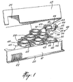
- Figure 1 illustrates a cap and well assembly 10 which comprises a tray or base plate 12 provided with a plurality of wells 14 and corresponding caps 16 .
- Assembly 10 may also include a cover 18 used for shipping or storage purposes.
- the preferred form of cover 18 comprises with an insertion (not shown) at each corner that allows retention of the cover over the caps without touching them.
- Cover 18 further allows the storage of several trays of experiments one on top of the other.
- Tray 12 comprises a rim 20 extending about the four side walls thereof, and is provided with finger grip surfaces 22 such as those described in US 4,038,149, on two opposed side walls for easier handling of the tray by the technician. Finger grip surfaces 22 are provided to avoid mishaps, and greatly facilitate handling of covered and uncovered trays.
- Cover 18 comprises a section 24 adapted to engage around finger grip surfaces 22 for proper fitting over assembly 10 .
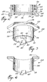
- FIG. 2 illustrates a section view of cap 16.
- cap 16 comprises a cylindrical slot 26 into which is inserted an O-ring element 28 made of a resilient material. Such material, although optional, is provided to ensure an appropriate seal when cap 16 is fitted over upper rim 30 of well 14 .
- the inner surface 32 of slot 26 has a portion or ridge 34 extending passed the planar surface 36 thereby forming a cavity 38 .
- Surface 36 may be concave or convex, but the planar configuration illustrated on Figure 2 is much preferred.
- the material of cap 16 is such that it is sufficiently transparent or translucent so that cap 16 can be placed directly under a microscope for observation and/or manipulation of the crystals.
- Each cap 16 comprises a pair of locking element 40 diametrically opposed to each other and comprising a ridge portion 41 .
- Cap 16 also comprises a further rim 46 provided with a series of spacer 45 underneath.
- Cap 16 is then rotated so that locking elements 40 slide each into a slot 43 having a width smaller than that of opening 42 and extending on a portion of the periphery of well 14 until the upper surface of portion 41 is entirely under upper surface 44 , thereby efficiently sealing well and maintaining cap 16 in place.
- a section 47 of portion 41 is tapered to facilitate sliding under upper surface 44 .
- a small bump (not shown) is provided onto section 49 that is adapted to fit into a corresponding recess (not shown) present under surface 44 after complete insertion of portion 41 under surface 44 .
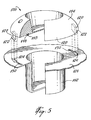
- Tool 48 may be used, as illustrated in Figures 3 and 4.
- Tool 48 comprises a body 50 divided in a portion 52 shaped in a manner such as to facilitate holding by the technician or an automated arm; a cylindrical portion 54 with an external surface 57 having a circumference slightly bigger than that of rim 46 , and an internal surface 59 having a circumference slightly smaller than that of rim 46 .
- Tool 48 further comprises two diametrically opposed cap gripping elements 60 each provided with a gripping finger 62 .
- the gripping element 60 can be provided onto internal surface 59 , directly on rim 66 , or onto external surface 57 .
- tool 48 is placed over cap 16 so that each finger 62 is inserted into a slot 64 cut into rim 46 until at least a portion 65 of each element 60 is abutted onto rim 46 .
- Tool 48 is then rotated until gripping fingers 62 are completely engaged under rim 46 , and the rotation is maintained until the locking members 40 are aligned with slots 42 .
- Cap 16 is then simply pulled up. To reintroduce the cap in position, the procedure is carried out in an opposite manner.
- the external surface 53 of portion 52 should be planar, so that it can be laid on a table or under a microscope in a stable manner, and allow the technician to observe and/or work on the crystals. To be able to work under a microscope directly, surface 53 must comprises an opening preferably corresponding to the internal diameter of cylindrical portion 54 (see Figure 4).
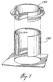
- FIG. 5 illustrates another embodiment of the present invention.
- the cap and well assembly 100 which comprises a tray or base plate (not shown) provided with a plurality of wells 112 and corresponding cap 114, which comprises a cylindrical slot 116 into which is inserted an O-ring element 118 made of a resilient material.
- the O-ring although optional, is provided to ensure an appropriate seal.
- Each cap 114 comprises a pair of locking element 120 diametrically opposed to each other and comprising a ridge portion 122 .
- Cap 114 is locked into position on the tray by inserting each locking element 120 into a corresponding opening 124 provided onto the upper surface 126 of the tray until the lower surface 128 of cap 114 lies flat onto the tray upper surface 126 .
- Cap 114 is then rotated so that locking elements 120 slide into a slot 130 having a width smaller than that of opening 124 and extending on a portion of the periphery of well 112 until the upper surface of ridge portion 122 is entirely under upper surface 126 , thereby efficiently sealing well and maintaining cap 114 in place.
- Figure 6 illustrates another simple variation of the present invention, wherein the upper surface 152 of a well 150 comprises a slot 154 along its circumference and adapted to receive an O-ring element 156 coupled to a cap 158 .
- the section of slot 154 is such that is slightly smaller than that of element 156 , so that upon insertion into the slot, a tight seal is formed by the locking of cap 158 to well 150 without the need of any adhesive or grease.
- Figure 7 illustrates yet another embodiment of the invention, wherein the cap 170 is screwed on the well 172 .
- the present cap and well assembly is particularly suitable for both hanging-drop or sitting-drop crystallization methods.
- sitting-drop method although not specifically illustrated in the drawings, anyone skilled in the art will readily appreciate that any conventional drop support can be inserted or molded into the well. Examples of such sitting-drop support include the Micro-BridgesTM or the glass sitting drop rods manufactured and sold by Hampton Research (Laguna Hills, California).
- each well is carefully filled with a selected equilibrating solution Subsequently, a selected protein drop is deposited on the cap.
- the shape and the texture of the lower surface can be varied to obtain optimum results for a particular protein solution being crystallized, for example, when lower surface tension solutions, including protein solutions containing detergents, are used.
- the addition of the equilibrating solution and the protein drops to the device may be carried out either manually or through commercial automated pipetting apparatus, and the sealing of the cap over the solution may also be carried out manually or in an automated manner.
Abstract
Description
- The present invention relates to a device for handling molecular and macromolecular crystallization. More particularly, the device comprises a well and a cap assembly for growing protein crystals by conventional vapor diffusion techniques. The present device is particularly advantageous in that it facilitates the pre-filling of the well with a solution for transport and handling prior to utilization by a technician.
- Crystallography is an extremely useful tool for scientists, and is therefore a field of research attracting a lot of interest. It is a powerful means that provides precise and detailed description of the three-dimensional structure of the molecules, and is of great help in the understanding of their functions. Crystallography of macromolecules like proteins is extensively used today, academically as well as industrially.
- Although three-dimensional structures of simple proteins have been obtained through crystallization methods, it is not always easy to obtain crystals from macromolecules. For example, the preferred conditions for the crystallization of a given molecule can take several hundreds if not thousands of trials. As a result, means and methods have been developed to perform a great number of trials relatively quickly, including hanging-drop and sitting-drop methods. All such methods use the benefit of vapor diffusion to obtain the crystals.
- The hanging-drop method is currently the most commonly used technique for scanning various crystallization conditions of macromolecules, such as proteins. It comprises suspending a droplet of approximately 2 to 20 µL of solution containing the macromolecule to be crystallized and a precipitating agent, over a precipitating solution, such as
conventional polyethylene glycol 20% orammonium sulfate 40%, contained in a reservoir or well. The system is then sealed hermetically. After a while, vapor diffusion of the solvent or solvent mixtures between the droplet and the solution in the reservoir reaches equilibrium. The end result is a decrease of water in the droplet, and an increase of the macromolecule and precipitating agent concentration therein, thus causing crystallization of the macromolecule in optimized conditions. The actual technique for the set up of the hanging-drop or sitting-drop experiments is a long and arduous work and has to be performed by qualified and skilled technical personnel. - Conventionally, a commercially available tray made of an inert thermoplastic material comprising a plurality of reservoirs or wells is prepared, and the precipitating solution is placed in each reservoir or well manually. The macromolecule solution is then mixed with a precipitating agent on a glass plate (coverglass) and the whole is inverted over the wells, thus making the macromolecule solution overhanging the well. Prior to placing a glass plate over a well, the rim of each well is greased to ensure a proper seal. Care must be taken when placing the plate over each well, since the grease can easily contaminate the macromolecule solution. The crystallization process is followed with the help of a microscope. After the crystal is obtained, the glass plate is removed. Again, this must be done with great care to prevent contamination of the crystallized macromolecule with grease, and/or breaking of the glass plate. On top of that, the plates are hardly reusable for any experiment because the grease is hard to remove, and some of it remains on the plates.
- An advantage of the hanging-drop and sitting-drop methods is that they provide screening conditions for crystallization, and truly represent a microcrystallization technique. The vapor diffusion in the hanging or sitting drop allows screening of a large range of conditions and necessitates a relatively small amount of macromolecules. Further, it allows a relatively clear visualization of the results, and the eventual crystals are free, i.e., they do not adhere or are stuck to any surface.
- Typically, several hundreds of experiments are required to find appropriate crystallizing conditions for the production of high quality crystals. Accordingly, hanging-drop and sitting-drop experiments are a very labor-intensive process demanding skilled and experienced technical personnel. For example, multiple aspirating and dispensing steps of components, multiple greasing steps etc. must be performed in the experimental set up. Further, for each well, a separate coverglass must be manually inverted. The number and complexity of steps can therefore produce an undesirable wide variation in experimental results.
- As stated above, grease is conventionally used to provide a seal between the well and the coverglass. Other ways for sealing the system have been proposed. For example, grease can be replaced with immersion oil or an adhesive tape. As with grease, these sealing means have serious drawbacks. Grease is not always easy to dispense around the upper rim of the well, and is a time consuming operation. Technicians repeating the operation thousands of times occasionally suffer physical pain to their hands. Other significant problems and risks are present when manipulating the crystal on a greasy cover slide. The cover slide sometimes breaks during the process, which may cause injury to the technician, in addition to losing the crystals. The immersion oil is also problematic. One has to use a determined volume of oil. Too much oil leads to contamination within the well, while not enough will lead to non-hermetic seal that may result in the evaporation of the precipitating solution. An adhesive tape allows quicker and simpler manipulations, but all experiments are sealed at the end of the set-up, thus introducing experimental variations between the 1st and the 24th drop. Further, crystals often stick to the tape, rendering impossible the recovery of the crystals, and the operations for the recovery of the drop are also problematic.
- These conditions promoted the robotization of the procedure. Some automated crystallization devices already exist. The well-known Cyberlab-200™ apparatus dispenses solutions in wells, greases the upper rim of each well, pours droplets on cover slides held by a vacuum arm, and places the cover slides over the wells. However, such apparatus still has some drawbacks, namely a complicated experimental set-up, and the notable use of grease. Further such apparatus is extremely expensive.
- Relevant references in the field include US-A-2,366,886; US-A-3,107,204; US-A-3,297,184; US-A-3,537,956; US-A-3,597,326; US-A-3,649,464; US-A-3,692,498; US-A-3,729,382; US-A-3,745,091; US-A-3,907,505; US-A-4,038,149; US-A-4,154,795; US-A-4,495,289; US-A-4,917,707; US-A-5,271,795; US-A-5,419,278 describes a vapor equilibrium apparatus for growing and screening protein crystals.
- It would therefore be highly desirable to develop a device for crystallizing macromolecules that would overcome the above deficiencies. Such device would eliminate the requirement of external means like grease, oil or an adhesive tape to seal the well and the cover, and would preferably be easy to manipulate, either manually or automatically. Ultimately, the process of experimental set up of the device would be greatly facilitated and accelerated, while simultaneously eliminating possible risks of contamination of the eventual crystals. Finally, such device should be usable for various crystallization processes such as hanging-drop or sitting-drop processes.
- In accordance with the present invention, there is provided a device according to claim 1 and a method according to
claim 20. Preferred embodiments are described in the dependent claims. -
- Figure 1 illustrates perspective view of a first cap and well assembly in accordance with the present invention;
- Figure 2 illustrates a section view of a preferred embodiment of a cap;
- Figure 3 illustrates a perspective view of a tool adapted to install and remove a cap from the well;
- Figure 4 illustrates a section view of the tool of Figure 3; and
- Figures 5, 6 and 7 illustrate other embodiments of the cap and well assembly according to the present invention.
-
- It is an object of the present invention to provide a crystal forming device using vapor diffusion method. The device comprises a well and a transparent cap designed to close the well and form a sealed volume, the well being sealed without the need to add a sealing material like grease, oil, adhesive tape and the like between the well and the cap. The cap is made of transparent material to allow examination and monitoring of crystal growth, as well as manipulation of the crystal under a microscope. The present device therefore represents an important advance in methods for growing crystals of macromolecules, especially in the field of hanging-drop and sitting-drop.
- Because of its simplicity, the operations of filling the well with the precipitating solution, placing a drop of the macromolecule solution onto the cap and sealing the well by putting the cap in position over the well can be accomplished by any competent technician, and not only skilled personnel.
- In a preferred embodiment of the invention, a plurality of wells are molded together, for example in a tray comprising 4 rows of 6 wells each, with corresponding transparent caps provided thereon. The resulting tray and caps may also be optionally treated with a hydrophobic agent such as a siliconing agent.
- Because of the transparency of the cap and of the bottom surface of the well, crystallization can be followed with minimal handling, and without disturbing the vapor equilibrium within each well. Further, visualization of the results under the microscope are simple because the cap is made of a transparent or translucent (clear) material.
- Preferably, the material of the tray and the cap are the same, and comprise materials that can be molded easily at a reasonable cost. The material should be stable for extended periods of time towards the various chemical products present in the well and onto the cap. The material should also preferably not absorb water, and be good optical quality to facilitate work and observation under a microscope. Example suitable materials include various thermoplastics such as polystyrene, polypropylene, polycarbonate, polyacrylate, polymethacrylate, acrylonitrile-styrene copolymers, nitrile-acrylonitrile-styrene copolymers, polyphenyleneoxide, phenoxy resins, etc., the most preferred material being polystyrene.
- It is another object of the present invention to provide a crystal-forming device that allows the manipulation of the growth crystals under the microscope without any transfer from the cap, where solutions can be added directly without any transfer of the crystals, in a greaseless environment.
- Another major advantage of the device of the present invention is that once a series of experiments is completed, the tray is readily reusable, simply by taking another series of caps containing a drop of a solution containing a macromolecule to be crystallized, and reinstalling the caps over the wells. Further, a given cap may be removed from its original well and locked onto another one containing a different precipitating solution.
- The invention is also concerned with a method for forming crystals of a macromolecule, the method comprising the steps of dispensing a precipitating solution in a well; forming a droplet in a cap comprising locking members to lock the cap over the well; and locking and sealing the well. In a preferred embodiment, a ring made of an elastomeric material like polypropylene, an ethylene-propylene copolymer, Teflon™ etc., is preferably provided between the cap and the well. In a further preferred embodiment, the well can be filled in advance and tightly sealed, so that they a tray is provided to a technician in a "ready-to-use" manner.
- Because of the ergonomics of the present invention, the cap is engaged easily so that there is no need for special manual dexterity comparatively to the use of conventional thin, fragile, microscope coverglasses. The presence of a cavity in the surface of the cap facing the bottom surface of the well allows the addition of liquid directly over the drop, after placing the cap upside down on a table, without the need to transfer the crystals to another well, thus limiting the manipulations that might ruin the fragile crystals.
- The use of the cap and well assembly of the present invention can be automated in a straightforward manner by providing the extremity of an automated arm with a simple grip element having an end provided with a structure adapted to releasably grip the cap. There is no need for the application of grease or the manipulation of fragile coverglass pieces. The grip element may also be manipulated manually by a technician, as described hereinbelow.
- The cap and well assembly of the present invention also finds applications in the field of cell cultures, molecular or cellular biology etc.
- In a most preferred embodiment of the invention, the well is filled beforehand and sealed with the cap. The technician therefore receives a "ready-to-use" assembly, thus eliminating the time-consuming operation of filling each well with the appropriate precipitating solution. The buyer may therefore order as many assemblies as desired with the same or different precipitating solutions. For shipping purposes, the cap may be replaced on the assembly with a film to prevent contact of the precipitating solution with the cap. Such contact would necessitate the cleaning of the cap prior to its use. One may also use a cap for shipping purposes, and a different cap to carry out the experiments. It is important that the well be sealed to avoid evaporation and spilling of the precipitating solution, either during shipment of the pre-filled wells, or during the experiments.
- Referring to the drawings which illustrate preferred embodiments of the invention, Figure 1 illustrates a cap and well assembly 10 which comprises a tray or
base plate 12 provided with a plurality ofwells 14 and correspondingcaps 16.Assembly 10 may also include acover 18 used for shipping or storage purposes. The preferred form ofcover 18 comprises with an insertion (not shown) at each corner that allows retention of the cover over the caps without touching them.Cover 18 further allows the storage of several trays of experiments one on top of the other.Tray 12 comprises arim 20 extending about the four side walls thereof, and is provided with finger grip surfaces 22 such as those described in US 4,038,149, on two opposed side walls for easier handling of the tray by the technician. Finger grip surfaces 22 are provided to avoid mishaps, and greatly facilitate handling of covered and uncovered trays.Cover 18 comprises asection 24 adapted to engage around finger grip surfaces 22 for proper fitting overassembly 10. - Figure 2 illustrates a section view of
cap 16. As it can be seen, cap 16 comprises acylindrical slot 26 into which is inserted an O-ring element 28 made of a resilient material. Such material, although optional, is provided to ensure an appropriate seal whencap 16 is fitted overupper rim 30 ofwell 14. Theinner surface 32 ofslot 26 has a portion orridge 34 extending passed theplanar surface 36 thereby forming acavity 38.Surface 36 may be concave or convex, but the planar configuration illustrated on Figure 2 is much preferred. As stated above, the material ofcap 16 is such that it is sufficiently transparent or translucent so thatcap 16 can be placed directly under a microscope for observation and/or manipulation of the crystals. - Each
cap 16 comprises a pair of lockingelement 40 diametrically opposed to each other and comprising aridge portion 41.Cap 16 also comprises afurther rim 46 provided with a series ofspacer 45 underneath. Once the precipitating solution is poured into well 14, the technician putscap 16 upside down on a flat surface and places a drop of the macromolecule-containing solution ontosurface 36.Cap 16 is then flipped over cautiously, and each lockingelement 40 is inserted into acorresponding opening 42 provided onto theupper surface 44 oftray 12 until the abutment ofupper rim 30 of well 14 with the O-ring element 28 insideslot 26 is achieved.Cap 16 is then rotated so that lockingelements 40 slide each into aslot 43 having a width smaller than that of opening 42 and extending on a portion of the periphery of well 14 until the upper surface ofportion 41 is entirely underupper surface 44, thereby efficiently sealing well and maintainingcap 16 in place. In a most preferred embodiment, asection 47 ofportion 41 is tapered to facilitate sliding underupper surface 44. To ensure even better locking and maintenance of the cap in position, a small bump (not shown) is provided ontosection 49 that is adapted to fit into a corresponding recess (not shown) present undersurface 44 after complete insertion ofportion 41 undersurface 44. - To put
cap 16 in place onto well 14, or for removal therefrom, atool 48 may be used, as illustrated in Figures 3 and 4.Tool 48 comprises abody 50 divided in aportion 52 shaped in a manner such as to facilitate holding by the technician or an automated arm; acylindrical portion 54 with anexternal surface 57 having a circumference slightly bigger than that ofrim 46, and aninternal surface 59 having a circumference slightly smaller than that ofrim 46.Tool 48 further comprises two diametrically opposedcap gripping elements 60 each provided with agripping finger 62. The grippingelement 60 can be provided ontointernal surface 59, directly onrim 66, or ontoexternal surface 57. In operation,tool 48 is placed overcap 16 so that eachfinger 62 is inserted into aslot 64 cut intorim 46 until at least aportion 65 of eachelement 60 is abutted ontorim 46.Tool 48 is then rotated until grippingfingers 62 are completely engaged underrim 46, and the rotation is maintained until the lockingmembers 40 are aligned withslots 42.Cap 16 is then simply pulled up. To reintroduce the cap in position, the procedure is carried out in an opposite manner. Theexternal surface 53 ofportion 52 should be planar, so that it can be laid on a table or under a microscope in a stable manner, and allow the technician to observe and/or work on the crystals. To be able to work under a microscope directly,surface 53 must comprises an opening preferably corresponding to the internal diameter of cylindrical portion 54 (see Figure 4). - Figure 5 illustrates another embodiment of the present invention. The cap and well assembly 100 which comprises a tray or base plate (not shown) provided with a plurality of
wells 112 andcorresponding cap 114, which comprises acylindrical slot 116 into which is inserted an O-ring element 118 made of a resilient material. As for the previous embodiment illustrated, the O-ring, although optional, is provided to ensure an appropriate seal. - Each
cap 114 comprises a pair of lockingelement 120 diametrically opposed to each other and comprising aridge portion 122.Cap 114 is locked into position on the tray by inserting each lockingelement 120 into acorresponding opening 124 provided onto theupper surface 126 of the tray until thelower surface 128 ofcap 114 lies flat onto the trayupper surface 126.Cap 114 is then rotated so that lockingelements 120 slide into aslot 130 having a width smaller than that ofopening 124 and extending on a portion of the periphery of well 112 until the upper surface ofridge portion 122 is entirely underupper surface 126, thereby efficiently sealing well and maintainingcap 114 in place. - Figure 6 illustrates another simple variation of the present invention, wherein the
upper surface 152 of a well 150 comprises aslot 154 along its circumference and adapted to receive an O-ring element 156 coupled to acap 158. The section ofslot 154 is such that is slightly smaller than that ofelement 156, so that upon insertion into the slot, a tight seal is formed by the locking ofcap 158 to well 150 without the need of any adhesive or grease. - Figure 7 illustrates yet another embodiment of the invention, wherein the
cap 170 is screwed on thewell 172. - The present cap and well assembly is particularly suitable for both hanging-drop or sitting-drop crystallization methods. With respect to the sitting-drop method, although not specifically illustrated in the drawings, anyone skilled in the art will readily appreciate that any conventional drop support can be inserted or molded into the well. Examples of such sitting-drop support include the Micro-Bridges™ or the glass sitting drop rods manufactured and sold by Hampton Research (Laguna Hills, California).
- Each well is carefully filled with a selected equilibrating solution Subsequently, a selected protein drop is deposited on the cap. The shape and the texture of the lower surface can be varied to obtain optimum results for a particular protein solution being crystallized, for example, when lower surface tension solutions, including protein solutions containing detergents, are used. The addition of the equilibrating solution and the protein drops to the device may be carried out either manually or through commercial automated pipetting apparatus, and the sealing of the cap over the solution may also be carried out manually or in an automated manner.
- While the invention has been described in connection with specific embodiments thereof, it will be understood that the present invention is equally applicable by making appropriate modifications to the embodiments described above, the invention being defined and limited only as indicated by the scope of the claims appended hereto.
Claims (22)
- A device for forming crystals by vapour diffusion, comprising a tray (12) provided with a plurality of wells (14; 112; 150; 172), each well of said plurality of wells being open at an upper end thereof for receiving a precipitating solution, whereby
said tray (12) comprises a top surface (44; 126), a bottom, and an upright peripheral wall extending from the top surface to the bottom,
said plurality of wells extending downwardly from the said top surface,
individual removable caps (16; 114; 158; 170) are provided for separately and independently covering each of a plurality of said wells,
each of said individual removable caps has an underside defining a support surface (36) for suspending a droplet of solution containing a molecule or a macromolecule to be crystallised over the precipitating solution contained in the associated well,
and said individual removable caps are sufficiently transparent for allowing examination and monitoring of crystal growth,
characterised in that:each of said individual removable caps are further provided with an integral locking member (40; 120; 156) engageable with a cooperating means (42, 43; 124, 130; 154) associated with each of said plurality of wells to releasably lock said individual removable caps to said plurality of wells in a sealed manner - The device according to claim 1, characterised in that the wells (14; 112; 150; 172) and the caps (16; 114; 158; 170) are cylindrical.
- The device according to claim 1, characterised in that a rim (30) of each well (14) extends above the top surface (44) of the tray (12).
- The device according to any one of claims 1 to 3, characterised in that the cap (16; 144) is tubular and said locking member comprises locking elements (40; 120) equally spaced apart, each locking element being lockingly insertable into a corresponding opening (42; 124) in the top surface of the tray adjacent to the rim of the well (14; 112).
- The device according to claim 4, characterised in that each cap comprises a tubular section around an external surface thereof, thereby defining a cylindrical slot (26) therebetween that is closed at a top of the slot (26), the slot (26) being adapted to receive therein the rim (30) of an associated well (14), the tubular section comprising the locking elements (40) coupled thereto.
- The device according to daim 4 or 5, characterised in that each locking member (40) comprises a tongue extending from top to bottom of the cap (16), the tongue comprising a portion (41) extending perpendicularly to the outside of the cap external surface.
- The device according to claim 1, characterised in that an O-ring element (156) is coupled to each cap (158) and an upper surface (152) of each well (150) comprises a slot (154) along its circumference adapted to receive the said O-ring element so as to lock the cap (158) to the well (150).
- The device according to claim 5, characterised in that an elastomeric material (28; 118) is inserted into the slot (26; 116) between the rim of the well and the top of the slot.
- The device according to claim 1, characterised in that each cap comprises a cavity (38) in a surface (36) facing bottom surface of the associated well (14) and being adapted to receive a drop of a molecule- or macromolecule-containing solution.
- The device according to claim 9, characterised in that the cavity (38) has a flat bottom surface.
- The device according to claim 10, characterised in that the cavity (38) comprises a circumferential wall (34) extending perpendicularly to the flat bottom surface (36).
- The device according to daim 2, characterised in that each cap comprises a rim (46) onto an external surface thereof, the rim comprising equally spaced apart slots (64).
- The device according to daim 12, characterised in that it further comprises a tool (48) for installing the cap on the well from an unlocked position to a locked position, or alternately, removing the cap from a locked position to an unlocked position, the tool comprising a cylindrical portion (54) and cap gripping elements (60) provided with gripping fingers (62) so as to cooperate with the slots (64) provided on the rim (46) of the cap for releasably gripping the cap, the tool further comprising a grip portion (52) for gripping by a technician or an automated arm.
- The device according to claim 1, characterised in that it further comprises a cover (18) disposed over and around the tray (12).
- The device according to claim 1, characterised in that the tray (12) further comprises equally spaced apart finger grip surfaces (22) on its circumferential wall.
- The device according to claim 1, characterised in that the tray (12) and the caps (16; 114; 158; 170) are made of a transparent or translucent material.
- The device according to claim 16, characterised in that the material is selected from a group of materials consisting of : polystyrene, polypropylene, polycarbonate, polyacrylate, polymethacrylate, acrylonitrile-styrene copolymers, nitrile-acrylonitrile-styrene copolymers, polyphenyleneoxide, phenoxy resins, and mixtures thereof.
- A device according to claims 1 to 6, characterised in that the locking member (40; 120) and the cooperating means (42, 43; 124, 130) are rotatably engageable with one another in order to lock or unlock the cap on or from the well.
- A device according to claim 18, characterised in that the locking member and the cooperating means are engageable by screwing the cap (170) on the well (172).
- A method for forming crystals by vapour diffusion, comprising the steps of dispensing a precipitating solution in a well (14) disposed in a tray (12),
providing a droplet of a solution containing a molecule or a macromolecule on a support surface (36), the support surface (36) being defined on the underside of a transparent cap (16), the cap (16) being provided for separately and independently covering a well which extends downwardly from a top surface (44) of the tray (12),
inverting the support surface (36) over the well (14) containing the precipitating solution so that the droplet is suspended over the precipitating solution,
locking the removable cap on said well by engaging characterised in that the method further comprises the step of an integral locking member (40) provided on the cap with a cooperating means (42, 43) associated with said well so as to seal the well. - The method according to claim 20, wherein the step of locking includes rotating the locking member (40) relative to the cooperating means (42, 43).
- The method according to claim 20, comprising the step of pre-filling the well (14) with the precipitating solution and sealing the well before shipment to a purchaser.
Applications Claiming Priority (3)
| Application Number | Priority Date | Filing Date | Title |
|---|---|---|---|
| CA002261326A CA2261326A1 (en) | 1999-02-09 | 1999-02-09 | Laboratory cap and well for hanging-drop crystallization methods |
| CA2261326 | 1999-02-09 | ||
| PCT/CA2000/000119 WO2000047323A1 (en) | 1999-02-09 | 2000-02-09 | Laboratory cap and well for hanging-drop crystallization methods |
Publications (2)
| Publication Number | Publication Date |
|---|---|
| EP1148946A1 EP1148946A1 (en) | 2001-10-31 |
| EP1148946B1 true EP1148946B1 (en) | 2004-05-12 |
Family
ID=4163275
Family Applications (1)
| Application Number | Title | Priority Date | Filing Date |
|---|---|---|---|
| EP00903455A Expired - Lifetime EP1148946B1 (en) | 1999-02-09 | 2000-02-09 | Laboratory cap and well for hanging-drop crystallization methods |
Country Status (11)
| Country | Link |
|---|---|
| US (2) | US7316805B1 (en) |
| EP (1) | EP1148946B1 (en) |
| JP (1) | JP4753107B2 (en) |
| KR (1) | KR20020013837A (en) |
| AT (1) | ATE266474T1 (en) |
| AU (1) | AU773384C (en) |
| CA (1) | CA2261326A1 (en) |
| DE (1) | DE60010657T2 (en) |
| DK (1) | DK1148946T3 (en) |
| IL (1) | IL144752A (en) |
| WO (1) | WO2000047323A1 (en) |
Families Citing this family (17)
| Publication number | Priority date | Publication date | Assignee | Title |
|---|---|---|---|---|
| US6797461B2 (en) | 2000-10-27 | 2004-09-28 | Promega Corporation | Tryptase substrates and assay for tryptase activity using same |
| JP3905399B2 (en) | 2002-02-25 | 2007-04-18 | プロテインウエーブ株式会社 | Biopolymer crystal generator |
| US20030235519A1 (en) * | 2002-06-24 | 2003-12-25 | Corning Incorporated | Protein crystallography hanging drop lid that individually covers each of the wells in a microplate |
| US7112241B2 (en) | 2002-12-31 | 2006-09-26 | Corning Incorporated | Protein crystallography hanging drop multiwell plate |
| CN100448503C (en) * | 2003-01-17 | 2009-01-07 | 纳克斯泰尔生物技术公司 | Pre-filled crystallization plates and methods for making and using same |
| AU2004205437B2 (en) | 2003-01-17 | 2009-10-01 | Molecular Dimensions, Inc. | Pre-filled crystallization plates and methods for making and using same |
| WO2006007702A1 (en) * | 2004-07-16 | 2006-01-26 | Nextal Biotechnologie Inc. | Method and apparatus for optimizing crystallization conditions of a substrate |
| KR101570545B1 (en) * | 2007-03-09 | 2015-11-19 | 넥서스 바이오시스템즈, 인코포레이티드. | Device and method for removing a peelable seal |
| WO2012098212A1 (en) * | 2011-01-20 | 2012-07-26 | 4Titude Limited | Microplate and multiwell strip with double rimmmed wells |
| EP2692911B1 (en) | 2011-03-31 | 2017-02-22 | Kunimine Industries Co., Ltd. | Use of agent for searching for protein crystallization conditions, and method for searching for protein crystallization conditions |
| US9075039B2 (en) | 2011-11-08 | 2015-07-07 | Becton, Dickinson And Company | Container and cap for a biological specimen |
| US9381524B2 (en) | 2011-11-08 | 2016-07-05 | Becton, Dickinson And Company | System and method for automated sample preparation |
| US9180461B2 (en) * | 2012-10-22 | 2015-11-10 | Qiagen Gaithersburg, Inc. | Condensation-reducing incubation cover |
| DE102013011534B4 (en) | 2013-07-10 | 2015-09-03 | Fraunhofer-Gesellschaft zur Förderung der angewandten Forschung e.V. | Culture vessel and method for culturing biological cells in hanging drops |
| KR102369640B1 (en) | 2016-03-02 | 2022-03-02 | 벡톤 디킨슨 앤드 컴퍼니 | Device for accessing screw-top containers in packaging and automation systems |
| GB201705870D0 (en) * | 2017-04-11 | 2017-05-24 | 4Titude Ltd | Improved sealing mat |
| FR3083785B1 (en) * | 2018-07-10 | 2020-06-19 | Technoflex | HOLDING DEVICE FOR CONTAINERS HAVING A FILLING HOSE AND USE OF SAID DEVICE |
Citations (2)
| Publication number | Priority date | Publication date | Assignee | Title |
|---|---|---|---|---|
| US4713219A (en) * | 1984-01-24 | 1987-12-15 | Eppendorf Geratebau Netheler & Hinz Gmbh | Plastic reaction vessel |
| EP0676643A2 (en) * | 1994-04-09 | 1995-10-11 | Roche Diagnostics GmbH | System for contamination-free reaction processes |
Family Cites Families (25)
| Publication number | Priority date | Publication date | Assignee | Title |
|---|---|---|---|---|
| US2366886A (en) | 1942-11-20 | 1945-01-09 | American Tag Company | Capsule handling apparatus |
| US3107204A (en) | 1961-01-23 | 1963-10-15 | Dalde Reagents Inc | Microbiological testing method and structure therefor |
| US3297184A (en) * | 1963-11-05 | 1967-01-10 | B D Lab Inc | Cap for culture tubes |
| US3537956A (en) | 1967-06-26 | 1970-11-03 | Joseph R Falcone | Petrie dish |
| US3597326A (en) | 1968-07-26 | 1971-08-03 | John Liner | Multi-dish laboratory unit |
| US3649464A (en) | 1969-12-05 | 1972-03-14 | Microbiological Ass Inc | Assay and culture tray |
| US3692498A (en) | 1970-10-12 | 1972-09-19 | Lab Aids Inc | Chemical testing apparatus |
| US3745091A (en) | 1970-11-18 | 1973-07-10 | Miles Lab | Biological reaction chamber apparatus |
| US3729382A (en) | 1970-12-09 | 1973-04-24 | Becton Dickinson Co | Microorganism sampling dish |
| US3907505A (en) | 1973-05-30 | 1975-09-23 | Miles Lab | Selectively detachable apparatus |
| US3860136A (en) * | 1974-01-30 | 1975-01-14 | Child Resistant Packaging Inc | Child-resistant enclosure for hazardous materials |
| US4038149A (en) * | 1975-12-31 | 1977-07-26 | Linbro Scientific, Inc. | Laboratory trays with lockable covers |
| US4154795A (en) | 1976-07-23 | 1979-05-15 | Dynatech Holdings Limited | Microtest plates |
| US4495289A (en) | 1981-03-17 | 1985-01-22 | Data Packaging Corporation | Tissue culture cluster dish |
| US4599314A (en) * | 1983-06-14 | 1986-07-08 | Hsc Research Development Corporation | Multiple vessel specimen tray with lid for releasably adhering vessel covers |
| FR2604917B1 (en) | 1986-10-09 | 1989-01-27 | Aerospatiale | CRYSTALLOGENESIS METHOD, CELL AND DEVICE, ESPECIALLY BY SPACE VESSEL |
| US4829006A (en) * | 1988-02-01 | 1989-05-09 | Difco Laboratories | Centrifugation vial and cluster tray |
| JPH04124082A (en) | 1990-09-14 | 1992-04-24 | Agency Of Ind Science & Technol | Formation of crystal |
| KR100236506B1 (en) * | 1990-11-29 | 2000-01-15 | 퍼킨-엘머시터스인스트루먼츠 | Apparatus for polymerase chain reaction |
| CA2120744A1 (en) * | 1991-10-09 | 1993-04-15 | David J. Kenyon | Crystal forming device and automated crystallization system |
| US5221410A (en) * | 1991-10-09 | 1993-06-22 | Schering Corporation | Crystal forming device |
| US5342581A (en) * | 1993-04-19 | 1994-08-30 | Sanadi Ashok R | Apparatus for preventing cross-contamination of multi-well test plates |
| US5419278A (en) * | 1994-05-25 | 1995-05-30 | Carter; Daniel C. | Vapor equilibration tray for growing protein crystals |
| US6074614A (en) * | 1995-06-07 | 2000-06-13 | Molecular Devices Corporation | Multi-assay plate cover for elimination of meniscus |
| US6027694A (en) * | 1996-10-17 | 2000-02-22 | Texperts, Inc. | Spillproof microplate assembly |
-
1999
- 1999-02-09 CA CA002261326A patent/CA2261326A1/en not_active Abandoned
-
2000
- 2000-02-09 JP JP2000598269A patent/JP4753107B2/en not_active Expired - Lifetime
- 2000-02-09 AU AU25291/00A patent/AU773384C/en not_active Expired
- 2000-02-09 DK DK00903455T patent/DK1148946T3/en active
- 2000-02-09 WO PCT/CA2000/000119 patent/WO2000047323A1/en not_active Application Discontinuation
- 2000-02-09 IL IL14475200A patent/IL144752A/en not_active IP Right Cessation
- 2000-02-09 AT AT00903455T patent/ATE266474T1/en not_active IP Right Cessation
- 2000-02-09 KR KR1020017010078A patent/KR20020013837A/en not_active Application Discontinuation
- 2000-02-09 DE DE60010657T patent/DE60010657T2/en not_active Expired - Lifetime
- 2000-02-09 EP EP00903455A patent/EP1148946B1/en not_active Expired - Lifetime
- 2000-09-02 US US09/913,088 patent/US7316805B1/en not_active Expired - Lifetime
-
2007
- 2007-04-05 US US11/784,157 patent/US20070184551A1/en not_active Abandoned
Patent Citations (2)
| Publication number | Priority date | Publication date | Assignee | Title |
|---|---|---|---|---|
| US4713219A (en) * | 1984-01-24 | 1987-12-15 | Eppendorf Geratebau Netheler & Hinz Gmbh | Plastic reaction vessel |
| EP0676643A2 (en) * | 1994-04-09 | 1995-10-11 | Roche Diagnostics GmbH | System for contamination-free reaction processes |
Also Published As
| Publication number | Publication date |
|---|---|
| AU773384B2 (en) | 2004-05-27 |
| KR20020013837A (en) | 2002-02-21 |
| JP4753107B2 (en) | 2011-08-24 |
| WO2000047323A1 (en) | 2000-08-17 |
| IL144752A (en) | 2005-03-20 |
| AU773384C (en) | 2004-12-23 |
| ATE266474T1 (en) | 2004-05-15 |
| CA2261326A1 (en) | 2000-08-09 |
| DK1148946T3 (en) | 2004-08-09 |
| DE60010657T2 (en) | 2005-02-10 |
| EP1148946A1 (en) | 2001-10-31 |
| AU2529100A (en) | 2000-08-29 |
| US20070184551A1 (en) | 2007-08-09 |
| JP2002536255A (en) | 2002-10-29 |
| IL144752A0 (en) | 2002-06-30 |
| US7316805B1 (en) | 2008-01-08 |
| DE60010657D1 (en) | 2004-06-17 |
Similar Documents
| Publication | Publication Date | Title |
|---|---|---|
| US20070184551A1 (en) | Crystallization Methods for laboratory cap and well | |
| US5096676A (en) | Crystal growing apparatus | |
| US5221410A (en) | Crystal forming device | |
| US5419278A (en) | Vapor equilibration tray for growing protein crystals | |
| US6656267B2 (en) | Tray for macromolecule crystallization and method of using the same | |
| US7993416B2 (en) | Pre-filled crystallization plates and methods for making and using same | |
| US6039804A (en) | Crystallization tray | |
| US5400741A (en) | Device for growing crystals | |
| US5873394A (en) | Automated sample preparation workstation for the vapor diffusion method of crystallization and method of preparation | |
| US10308381B2 (en) | Cap supply for vessels containing biological samples | |
| CA2120744A1 (en) | Crystal forming device and automated crystallization system | |
| CA2259030C (en) | Crystal growth method and solid-state component and apparatus for crystal growth employed therefor | |
| AU1087601A (en) | Mixing and pouring apparatus with rotatable arm and related vessel | |
| CA2360315C (en) | Laboratory cap and well for hanging-drop crystallization methods | |
| MXPA01008052A (en) | Laboratory cap and well for hanging-drop crystallization methods | |
| CN100448503C (en) | Pre-filled crystallization plates and methods for making and using same | |
| US20030015132A1 (en) | Stackable vapor-equilibration tray for cell culture and protein crystal growth | |
| JPH01225476A (en) | Culture instrument for liquid culture | |
| AU2007216758B2 (en) | Mixing and pouring apparatus |
Legal Events
| Date | Code | Title | Description |
|---|---|---|---|
| PUAI | Public reference made under article 153(3) epc to a published international application that has entered the european phase |
Free format text: ORIGINAL CODE: 0009012 |
|
| 17P | Request for examination filed |
Effective date: 20010813 |
|
| AK | Designated contracting states |
Kind code of ref document: A1 Designated state(s): AT BE CH CY DE DK ES FI FR GB GR IE IT LI LU MC NL PT SE |
|
| RAP1 | Party data changed (applicant data changed or rights of an application transferred) |
Owner name: NEXTAL BIOTECHNOLOGIE INC. |
|
| 17Q | First examination report despatched |
Effective date: 20020708 |
|
| GRAP | Despatch of communication of intention to grant a patent |
Free format text: ORIGINAL CODE: EPIDOSNIGR1 |
|
| GRAS | Grant fee paid |
Free format text: ORIGINAL CODE: EPIDOSNIGR3 |
|
| GRAA | (expected) grant |
Free format text: ORIGINAL CODE: 0009210 |
|
| AK | Designated contracting states |
Kind code of ref document: B1 Designated state(s): AT BE CH CY DE DK ES FI FR GB GR IE IT LI LU MC NL PT SE |
|
| PG25 | Lapsed in a contracting state [announced via postgrant information from national office to epo] |
Ref country code: BE Free format text: LAPSE BECAUSE OF FAILURE TO SUBMIT A TRANSLATION OF THE DESCRIPTION OR TO PAY THE FEE WITHIN THE PRESCRIBED TIME-LIMIT Effective date: 20040512 Ref country code: AT Free format text: LAPSE BECAUSE OF FAILURE TO SUBMIT A TRANSLATION OF THE DESCRIPTION OR TO PAY THE FEE WITHIN THE PRESCRIBED TIME-LIMIT Effective date: 20040512 Ref country code: FI Free format text: LAPSE BECAUSE OF FAILURE TO SUBMIT A TRANSLATION OF THE DESCRIPTION OR TO PAY THE FEE WITHIN THE PRESCRIBED TIME-LIMIT Effective date: 20040512 |
|
| REG | Reference to a national code |
Ref country code: GB Ref legal event code: FG4D |
|
| REG | Reference to a national code |
Ref country code: CH Ref legal event code: EP |
|
| REG | Reference to a national code |
Ref country code: IE Ref legal event code: FG4D |
|
| REF | Corresponds to: |
Ref document number: 60010657 Country of ref document: DE Date of ref document: 20040617 Kind code of ref document: P |
|
| REG | Reference to a national code |
Ref country code: DK Ref legal event code: T3 |
|
| PG25 | Lapsed in a contracting state [announced via postgrant information from national office to epo] |
Ref country code: GR Free format text: LAPSE BECAUSE OF FAILURE TO SUBMIT A TRANSLATION OF THE DESCRIPTION OR TO PAY THE FEE WITHIN THE PRESCRIBED TIME-LIMIT Effective date: 20040812 |
|
| PG25 | Lapsed in a contracting state [announced via postgrant information from national office to epo] |
Ref country code: ES Free format text: LAPSE BECAUSE OF FAILURE TO SUBMIT A TRANSLATION OF THE DESCRIPTION OR TO PAY THE FEE WITHIN THE PRESCRIBED TIME-LIMIT Effective date: 20040823 |
|
| REG | Reference to a national code |
Ref country code: SE Ref legal event code: TRGR |
|
| REG | Reference to a national code |
Ref country code: CH Ref legal event code: NV Representative=s name: MICHELI & CIE INGENIEURS-CONSEILS |
|
| ET | Fr: translation filed | ||
| PG25 | Lapsed in a contracting state [announced via postgrant information from national office to epo] |
Ref country code: CY Free format text: LAPSE BECAUSE OF FAILURE TO SUBMIT A TRANSLATION OF THE DESCRIPTION OR TO PAY THE FEE WITHIN THE PRESCRIBED TIME-LIMIT Effective date: 20050209 Ref country code: LU Free format text: LAPSE BECAUSE OF NON-PAYMENT OF DUE FEES Effective date: 20050209 Ref country code: IE Free format text: LAPSE BECAUSE OF NON-PAYMENT OF DUE FEES Effective date: 20050209 |
|
| PG25 | Lapsed in a contracting state [announced via postgrant information from national office to epo] |
Ref country code: MC Free format text: LAPSE BECAUSE OF NON-PAYMENT OF DUE FEES Effective date: 20050228 |
|
| PLBE | No opposition filed within time limit |
Free format text: ORIGINAL CODE: 0009261 |
|
| STAA | Information on the status of an ep patent application or granted ep patent |
Free format text: STATUS: NO OPPOSITION FILED WITHIN TIME LIMIT |
|
| 26N | No opposition filed |
Effective date: 20050215 |
|
| REG | Reference to a national code |
Ref country code: IE Ref legal event code: MM4A |
|
| PG25 | Lapsed in a contracting state [announced via postgrant information from national office to epo] |
Ref country code: PT Free format text: LAPSE BECAUSE OF NON-PAYMENT OF DUE FEES Effective date: 20041012 |
|
| REG | Reference to a national code |
Ref country code: NL Ref legal event code: TD Effective date: 20110228 |
|
| REG | Reference to a national code |
Ref country code: CH Ref legal event code: PFA Owner name: QIAGEN CANADA INC. Free format text: NEXTAL BIOTECHNOLOGIE INC.#1751 RICHARDSON BUREAU 6101#MONTREAL (QUEBEC) H3K 2G6 (CA) -TRANSFER TO- QIAGEN CANADA INC.#1751 RICHARDSON BUREAU 6101#MONTREAL (QUEBEC) H3K 2G6 (CA) |
|
| REG | Reference to a national code |
Ref country code: DE Ref legal event code: R081 Ref document number: 60010657 Country of ref document: DE Owner name: QIAGEN CANADA INC., MONTREAL, CA Free format text: FORMER OWNER: NEXTAL BIOTECHNOLOGIE INC., MONTREAL, QUEBEC, CA Effective date: 20110428 Ref country code: DE Ref legal event code: R081 Ref document number: 60010657 Country of ref document: DE Owner name: QIAGEN CANADA INC., CA Free format text: FORMER OWNER: NEXTAL BIOTECHNOLOGIE INC., MONTREAL, CA Effective date: 20110428 |
|
| REG | Reference to a national code |
Ref country code: FR Ref legal event code: CD |
|
| REG | Reference to a national code |
Ref country code: FR Ref legal event code: PLFP Year of fee payment: 17 |
|
| REG | Reference to a national code |
Ref country code: FR Ref legal event code: PLFP Year of fee payment: 18 |
|
| REG | Reference to a national code |
Ref country code: FR Ref legal event code: PLFP Year of fee payment: 19 |
|
| PGFP | Annual fee paid to national office [announced via postgrant information from national office to epo] |
Ref country code: NL Payment date: 20190218 Year of fee payment: 20 |
|
| PGFP | Annual fee paid to national office [announced via postgrant information from national office to epo] |
Ref country code: IT Payment date: 20190225 Year of fee payment: 20 Ref country code: GB Payment date: 20190218 Year of fee payment: 20 Ref country code: DE Payment date: 20190219 Year of fee payment: 20 Ref country code: CH Payment date: 20190218 Year of fee payment: 20 |
|
| PGFP | Annual fee paid to national office [announced via postgrant information from national office to epo] |
Ref country code: SE Payment date: 20190218 Year of fee payment: 20 Ref country code: DK Payment date: 20190220 Year of fee payment: 20 Ref country code: FR Payment date: 20190219 Year of fee payment: 20 |
|
| REG | Reference to a national code |
Ref country code: DE Ref legal event code: R082 Ref document number: 60010657 Country of ref document: DE Ref country code: DE Ref legal event code: R081 Ref document number: 60010657 Country of ref document: DE Owner name: MOLECULAR DIMENSIONS, INC., MAUMEE, US Free format text: FORMER OWNER: QIAGEN CANADA INC., MONTREAL, QUEBEC, CA |
|
| REG | Reference to a national code |
Ref country code: DE Ref legal event code: R071 Ref document number: 60010657 Country of ref document: DE |
|
| REG | Reference to a national code |
Ref country code: DK Ref legal event code: EUP Effective date: 20200209 |
|
| REG | Reference to a national code |
Ref country code: NL Ref legal event code: MK Effective date: 20200208 |
|
| REG | Reference to a national code |
Ref country code: CH Ref legal event code: PL |
|
| REG | Reference to a national code |
Ref country code: GB Ref legal event code: 732E Free format text: REGISTERED BETWEEN 20200130 AND 20200205 |
|
| REG | Reference to a national code |
Ref country code: GB Ref legal event code: PE20 Expiry date: 20200208 |
|
| REG | Reference to a national code |
Ref country code: SE Ref legal event code: EUG |
|
| PG25 | Lapsed in a contracting state [announced via postgrant information from national office to epo] |
Ref country code: GB Free format text: LAPSE BECAUSE OF EXPIRATION OF PROTECTION Effective date: 20200208 |