EP1148673A2 - Idendification of a base station, using latin-square hopping sequences, in multicarrier spread-spectrum systems - Google Patents
Idendification of a base station, using latin-square hopping sequences, in multicarrier spread-spectrum systems Download PDFInfo
- Publication number
- EP1148673A2 EP1148673A2 EP01303316A EP01303316A EP1148673A2 EP 1148673 A2 EP1148673 A2 EP 1148673A2 EP 01303316 A EP01303316 A EP 01303316A EP 01303316 A EP01303316 A EP 01303316A EP 1148673 A2 EP1148673 A2 EP 1148673A2
- Authority
- EP
- European Patent Office
- Prior art keywords
- slope
- frequency shift
- pilot tone
- pilot
- tone hopping
- Prior art date
- Legal status (The legal status is an assumption and is not a legal conclusion. Google has not performed a legal analysis and makes no representation as to the accuracy of the status listed.)
- Withdrawn
Links
Images


Classifications
-
- H—ELECTRICITY
- H04—ELECTRIC COMMUNICATION TECHNIQUE
- H04B—TRANSMISSION
- H04B1/00—Details of transmission systems, not covered by a single one of groups H04B3/00 - H04B13/00; Details of transmission systems not characterised by the medium used for transmission
- H04B1/69—Spread spectrum techniques
- H04B1/713—Spread spectrum techniques using frequency hopping
- H04B1/7143—Arrangements for generation of hop patterns
-
- H—ELECTRICITY
- H04—ELECTRIC COMMUNICATION TECHNIQUE
- H04B—TRANSMISSION
- H04B1/00—Details of transmission systems, not covered by a single one of groups H04B3/00 - H04B13/00; Details of transmission systems not characterised by the medium used for transmission
- H04B1/69—Spread spectrum techniques
- H04B1/713—Spread spectrum techniques using frequency hopping
- H04B1/7156—Arrangements for sequence synchronisation
-
- H—ELECTRICITY
- H04—ELECTRIC COMMUNICATION TECHNIQUE
- H04L—TRANSMISSION OF DIGITAL INFORMATION, e.g. TELEGRAPHIC COMMUNICATION
- H04L27/00—Modulated-carrier systems
- H04L27/26—Systems using multi-frequency codes
- H04L27/2601—Multicarrier modulation systems
- H04L27/2602—Signal structure
- H04L27/261—Details of reference signals
- H04L27/2613—Structure of the reference signals
-
- H—ELECTRICITY
- H04—ELECTRIC COMMUNICATION TECHNIQUE
- H04L—TRANSMISSION OF DIGITAL INFORMATION, e.g. TELEGRAPHIC COMMUNICATION
- H04L27/00—Modulated-carrier systems
- H04L27/26—Systems using multi-frequency codes
- H04L27/2601—Multicarrier modulation systems
- H04L27/2647—Arrangements specific to the receiver only
- H04L27/2655—Synchronisation arrangements
- H04L27/2657—Carrier synchronisation
-
- H—ELECTRICITY
- H04—ELECTRIC COMMUNICATION TECHNIQUE
- H04L—TRANSMISSION OF DIGITAL INFORMATION, e.g. TELEGRAPHIC COMMUNICATION
- H04L27/00—Modulated-carrier systems
- H04L27/26—Systems using multi-frequency codes
- H04L27/2601—Multicarrier modulation systems
- H04L27/2647—Arrangements specific to the receiver only
- H04L27/2655—Synchronisation arrangements
- H04L27/2668—Details of algorithms
- H04L27/2673—Details of algorithms characterised by synchronisation parameters
- H04L27/2675—Pilot or known symbols
-
- H—ELECTRICITY
- H04—ELECTRIC COMMUNICATION TECHNIQUE
- H04L—TRANSMISSION OF DIGITAL INFORMATION, e.g. TELEGRAPHIC COMMUNICATION
- H04L5/00—Arrangements affording multiple use of the transmission path
- H04L5/0001—Arrangements for dividing the transmission path
- H04L5/0014—Three-dimensional division
- H04L5/0016—Time-frequency-code
- H04L5/0019—Time-frequency-code in which one code is applied, as a temporal sequence, to all frequencies
-
- H—ELECTRICITY
- H04—ELECTRIC COMMUNICATION TECHNIQUE
- H04L—TRANSMISSION OF DIGITAL INFORMATION, e.g. TELEGRAPHIC COMMUNICATION
- H04L5/00—Arrangements affording multiple use of the transmission path
- H04L5/003—Arrangements for allocating sub-channels of the transmission path
- H04L5/0048—Allocation of pilot signals, i.e. of signals known to the receiver
-
- H—ELECTRICITY
- H04—ELECTRIC COMMUNICATION TECHNIQUE
- H04B—TRANSMISSION
- H04B1/00—Details of transmission systems, not covered by a single one of groups H04B3/00 - H04B13/00; Details of transmission systems not characterised by the medium used for transmission
- H04B1/69—Spread spectrum techniques
- H04B1/713—Spread spectrum techniques using frequency hopping
- H04B1/7156—Arrangements for sequence synchronisation
- H04B2001/71563—Acquisition
-
- H—ELECTRICITY
- H04—ELECTRIC COMMUNICATION TECHNIQUE
- H04L—TRANSMISSION OF DIGITAL INFORMATION, e.g. TELEGRAPHIC COMMUNICATION
- H04L25/00—Baseband systems
- H04L25/02—Details ; arrangements for supplying electrical power along data transmission lines
- H04L25/0202—Channel estimation
- H04L25/0224—Channel estimation using sounding signals
- H04L25/0226—Channel estimation using sounding signals sounding signals per se
Abstract
Description
- United States Patent application Serial No. (R. Laroia-J. Li-S. V. Uppala Case 16-9-4) was filed concurrently herewith.
- This invention relates to wireless communications systems and, more particularly, to orthogonal frequency division multiplexing (OFDM) based spread spectrum multiple access (SSMA) systems.
- It is important that wireless communications systems be such as to maximize the number of users that can be adequately served and to maximize data transmission rates, if data services are provided. Wireless communications systems are typically shared media systems, i.e., there is a fixed available bandwidth that is shared by all users of the wireless system. Such wireless communications systems are often implemented as so-called "cellular" communications systems, in which the territory being covered is divided into separate cells, and each cell is served by a base station.
- In such systems, it is important that mobile user units are rapidly able to identify and synchronize to the downlink of a base station transmitting the strongest signal. Prior arrangements have transmitted training symbols periodically for mobile user units to detect and synchronize to the associated base station downlink. In such arrangements, there is a large probability that delays occur in identifying the base station transmitting the strongest signal because the training symbols are typically transmitted at the beginning of a frame. It is also likely that the training symbols transmitted from different base stations would interfere with each other. Indeed, it is known that once the training symbols interfere with each other they will continue to interfere. Thus, if the training symbols are corrupted, then the data is also corrupted, thereby causing loss in efficiency.
- Problems and/or limitations related to prior mobile user units that have attempted to identify a base station having the strongest downlink signal are addressed by utilizing a pilot tone hopping sequence being transmitted by a base station. Specifically, base station identification is realized by determining the slope of the strongest received pilot signal, i.e., the received pilot signal having the maximum energy.
- In an embodiment of the invention, the pilot tone hopping sequence is based on a Latin Squares sequence. With a Latin Squares based pilot tone hopping sequence, all a mobile user unit needs is to locate the frequency of the pilot tones at one time because the pilot tone locations at subsequent times can be determined from the unique slope of the Latin Squares pilot tone hopping sequence. The slope and initial frequency shift of the pilot tone hopping sequence with the strongest received power is determined by employing a unique maximum energy detector. This unique slope of the pilot tone hopping sequence is then advantageously employed to identify the base station having the strongest downlink signal.
- In one embodiment, the slope and initial frequency shift of the pilot signal having the strongest received power is determined by finding the slope and initial frequency shift of a predicted set of pilot tone locations having the maximum received energy.
- In another embodiment, the frequency offset of the pilot signal with the strongest, i.e., maximum, received power is estimated at each of times "t". These frequency offsets are employed in accordance with a prescribed relationship to determine the unknown slope and the initial frequency shift of the pilot signal.
- A technical advantage to using the pilot tone hopping sequence to identify the base station having the strongest downlink signal is that the inherent latency resulting from using a sequence of training symbols is not present.
-
- FIG. 1 illustrates a frequency domain representation in which a prescribed plurality of tones is generated in a prescribed bandwidth;
- FIG. 2 illustrates a time domain representation of a tone fi ;
- FIG. 3 is a graphical representation of a time-frequency grid including a pilot tone hopping sequence;
- FIG. 4 is a graphical representation of a Latin Squares hopping sequence;
- FIG. 5 shows, in simplified block form, an OFDM-SSMA cellular system with Latin Squares pilots;
- FIG. 6 shows, in simplified block diagram form, details of a mobile user unit in which an embodiment of the invention may advantageously be employed;
- FIG. 7 shows, in simplified block diagram for, details of an embodiment of a maximum energy detector that may be employed in the mobile user unit of FIG. 6;
- FIG. 8 shows, in simplified block diagram form, details of another embodiment of a maximum energy detector that may be employed in the mobile user unit of FIG. 6; and
- FIG. 9 is a flow chart illustrating steps in a process that may be employed in the slope-shift solver of FIG. 8.
-
- FIG. 1 illustrates a frequency domain representation in which a prescribed plurality of tones is generated in a prescribed bandwidth. In this example, bandwidth W is employed to generate a total of N tones, i.e., i=1,...,N. The tones are spaced at Δf = 1/TS apart, where Ts is the duration of an OFDM symbol. Note that the tones employed in this embodiment of the invention are generated differently than those generated for a narrow band system. Specifically, in a narrow band system the energy from each tone is strictly confined to a narrow bandwidth centered around the tone frequency, whereas in an Orthogonal Frequency Division Multiplexing (OFDM) system that is a wide band system the energy at a particular tone is allowed to leak into the entire bandwidth W, but it is so arranged that the tones do not interfere with one another.
- FIG. 2 illustrates a time domain representation of tone fi within symbol interval Ts . Again, note that within each symbol interval Ts , data may be transmitted on each of the tones substantially simultaneously.
- FIG. 3 is a graphical representation of an example OFDM channel from a base station to a number of mobile user units, i.e., receivers. The OFDM channel is represented as a time-frequency grid, i.e., plane. Each column of the grid represents the time interval for one OFDM symbol interval, and each OFDM symbol is comprised of a number of tones. In this example, there are N=5 tones in each symbol interval. The tones are numbered along the frequency axis and the symbol intervals, i.e., periods, are numbered along the time axis. If the spacing between tones in FIG. 3 is Δf, then:
-
tone 0 corresponds to f; -
tone 1 corresponds to f + Δf ; -
tone 2 corresponds to f + 2Δf ; -
tone 3 corresponds to f + 3Δf ; -
tone 4 corresponds to f + 4Δf.
Similarly, if the duration of a symbol interval is Ts then:
-
time 0 corresponds to t 0; -
time 1 corresponds to t 0 + Ts ; -
time 2 corresponds to t 0 + 2 Ts ; -
time 3 corresponds to t 0 + 3 Ts ; -
time 4 corresponds to t 0 + 4Ts ; -
time 5 corresponds to t 0 + 5 Ts ; -
time 6 corresponds to t 0 + 6Ts . -
- In general, a pilot signal includes known waveforms that are transmitted from a base station so that mobile user units, i.e., receivers, can identify the base station and estimate various channel parameters. In an Orthogonal Frequency Division Multiplexing based Spread Spectrum Multiple Access (OFDM-SSMA) system, in accordance with an aspect of the invention, the pilot signal is comprised of known symbols transmitted on prescribed tones during prescribed symbol intervals. In a given symbol interval, the tones used for the pilot signal are called the "pilot tones", and the assignment of pilot tones as a function of time is called the "pilot hopping sequence". Again, it is noted that the inherent delays resulting when using the training sequence of symbols is not experienced when using the pilot tone hopping sequence to identify the base station having the strongest downlink signal.
- Since the OFDM-SSMA physical layer is based on the pilot signals, symbols on the pilot tones are transmitted at higher power than symbols on non-pilot tones. Pilot tones are also boosted in power so that they may be received throughout the cell. Therefore, for the purpose of identification, pilot signals can be distinguished by the fact that the energy received on the pilot tones is higher than the energy on the non-pilot tones.
- In FIG. 3, an example set of pilot tones is indicated by the hatched squares in the time-frequency grid. In this example, the base station transmits one pilot tone in each OFDM symbol interval. During: symbol interval (0), tone (1) is used as a pilot tone; symbol interval (1), tone (4) is used as a pilot tone; symbol interval (2), tone (0) is used as a pilot tone; symbol interval (3), tone (2) is used as a pilot tone; symbol interval (4), tone (4) is used as a pilot tone; symbol interval (5), tone (1) is used as a pilot tone; etc...
- FIG. 4 shows an example of a Latin Squares pilot hopping sequence. The pilot signal corresponding to a Latin Squares pilot hopping sequence will be called a "Latin Squares pilot signal", or simply "Latin Squares pilot". In a Latin Squares pilot hopping sequence, the number of tones, N, is a prime number, and the pilot signals are transmitted on a fixed number, Np , of the N tones in each OFDM symbol interval. The tone number of the j-th pilot tone in the t-th symbol interval is given by,
- The frequency offsets and slope are design parameters of the Latin Squares pilot signal. For the purpose of channel estimation, the frequency offsets and slope should be selected so that the pilot tones are close to uniformly distributed in the time-frequency plane. A uniform distribution minimizes the worst-case interpolation error in the channel estimation. Specific values for the frequency offsets and slopes can be tested by numerical simulation with a specific channel estimator and channel conditions.
- FIG. 5 depicts an OFDM-SSMA cellular system using Latin Squares pilots. The figure shows two
base stations base station mobile user unit 503, denoted MS, receives pilots signals and other transmissions from one or more base stations in the cellular system. The Latin Squares pilots transmitted by all thebase stations - The base station identification problem is for the
mobile user unit 503 to estimate the slope, s ∈ S, of the strongest received pilot signal. To perform this identification, themobile user unit 503 can be pre-programmed with the common pilot signal parameters, N , Np and nj , as well as the set of possible slopes, S. - In general, base station identification is conducted prior to downlink and carrier synchronization. Consequently, a
mobile user unit 503 may receive the pilot signals with unknown frequency and timing errors, and mobile user units must be able to perform base station identification in the presence of these errors. Also, after identifying the pilot hopping sequence of the strongest base station, the mobile user unit must synchronize its timing and carrier so that the location of subsequent pilot tones can be determined. - To define this synchronization problem more precisely, let Δt denote the timing error between a base station and mobile user unit in number of OFDM symbol intervals, and Δn denote the frequency error in number of tones. For the time being, it is assumed that ▵t and ▵n are both integer errors. Fractional errors will be considered later. Under integer time and frequency errors, ▵t and ▵n, if a base station transmits a pilot sequence given by Equation (1), the j-th pilot tone in the t-th symbol interval of the mobile will appear on tone number,
- The fact that synchronization requires only the estimation of the initial frequency shift is a particular and useful feature of the Latin Square pilot hopping sequences. In general, synchronization involves estimation of time and frequency errors, and therefore demands a two parameter search. Synchronization for the Latin Squares sequences considered here, however, only requires the estimation of one parameter.
- In summary, in an OFDM-SSMA cellular system, each base station transmits a Latin Squares pilot signal with a locally unique slope. A mobile user unit performs base station identification by estimating the slope of the strongest received pilot signal. In addition, the mobile user unit can synchronize to the pilot signal by estimating its initial frequency shift.
- FIG. 6 shows, in simplified block diagram form, the details of a mobile user unit 600 containing the proposed maximum energy detector for base station identification. An incoming signal is supplied via an
antenna 601 to adown conversion unit 602. The incoming signal includes pilot signals from one or more base stations. Downconversion unit 602 yields the baseband signal r(t) from the signal received by the mobile user unit 600. The received signal r(t) is supplied to fast Fourier transform (FFT)unit 603 that during each OFDM symbol interval performs an FFT on it to yield Y(t,n). In this example, Y(t,n) denotes the complex value received on the n-th tone in the t-th symbol interval and is supplied tomaximum energy detector 604 and toreceiver 605.Maximum energy detector 604 uses FFT data Y(t,n) from Nsy consecutive OFDM symbols to estimate the slope and initial frequency shift of the pilot signal with the maximum received strength. As indicated above, the FFT symbols to be used for the base station identification are denoted Y(t,n), t=0,...,Nsy -1 and n=0,..., N-1, and the estimates of the slope and initial frequency shift of the strongest received pilot signal are denoted s and and b and 0, respectively. The pilot slope s and and initial frequency shift b and 0 estimates are supplied to areceiver 605 and employed to synchronizereceiver 605 to the incoming carrier and to locate subsequent symbols in the pilot signal. - FIG. 7 shows, in simplified block diagram form details of an embodiment of a
maximum energy detector 604 that may be employed in the mobile user unit 600 of FIG. 6. It has been seen that for the Latin Squares pilot tones, each candidate slope, s, and frequency shift, b 0 = b(0), corresponds to a set of predicted pilot tone locations, (t,n), withb maximum energy detector 604 of FIG. 6 is the FFT data, Y(t,n),t=0,...,Nsy -1 and n=0, ..., N-1. The slope-shift accumulator 701, accumulates the energy along each possible slope, s, and initial frequency shift, b 0. The accumulated energy is given by the signal:Then,
frequency shift accumulator 702 accumulates the energy along the pilot frequency shifts, namely:
Maximum detector 703 estimates the slope and frequency shift of the maximum energy pilot signal as the slope and frequency shifts corresponding to the maximum accumulated pilot energy, that is:where the maximum is taken over s ∈ S and b 0 = 0,..., N-1.
- Unfortunately, in certain applications, the above computations of Equations (5), (6) and (7) may be difficult to perform in a. reasonable amount of time with the processing power available at the mobile user unit 600. To see this, note that to compute J 0 (s,b 0) in Equation (5) at a single point (s,b 0) requires Nsy additions. Therefore, to compute J 0(s,b 0)at all (s,b 0) requires NNslNsy additions, where Nsl is the number of slopes in the slope set S. Similarly, computing J(s,b 0) in Equation (6) requires NNslNp additions. Therefore, the complete energy detector would require O(NNsl (Np + Nsy )) basic operations to perform. Therefore, for typical values such as N=400, Nsl =200, Np = 10 and Nsy = 20, the full energy detector would require 2.4 million operations. This computation may be difficult for the mobile user unit 600 to perform in a suitable amount of time.
- FIG. 8 shows, in simplified block diagram form details of another embodiment of a maximum energy detector that may be employed in the mobile user unit of FIG. 6.
Symbolwise shift detector 801 estimates, at each time t, the frequency shift of the pilot signal with strongest received strength. Specifically, the block computes:where E(t) is the maximum energy value and n(t) is the argument of the maximum. To understand the purpose of the computation in Equation (8), suppose that the tones of the strongest energy pilot signal appear at the locations, (t,n), given in Equation (4). Since the received energy |Y(t,n)|2, will usually be maximum at these pilot tone locations, the maximization in Equation (9) will typically result in: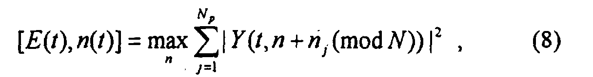
- Slope-
shift solver 802 uses the relation in Equation (9) and the frequency offset estimates, n(t), to determine the unknown slope, s, and initial frequency shift, b 0. Since, the pilot signals are only on average higher in power than the non-pilot tones, the relation of Equation (9) may not hold at all time points t. Therefore, the slope-shift solver 802. must be robust against some of the data points n(t) not satisfying Equation (9). For robustness, the value E(t) can be used as measure of the reliability of the data n(t). Larger values of E(t) imply a larger amount of energy captured at the frequency shift estimate, n(t), and such values of n(t) can therefore be considered more reliable. - One possible way of implementing a robust slope-
shift solver 802 is referred to as the difference method. This method uses the fact that if n(t) and n(t-1) both satisfy Equation (10), then n(t)-n(t-1) =s. Therefore, the slope, s, can be estimated by:where 1 is the indicator function. The estimator as defined by Equation (10) finds the slope, s, on which the total received pilot energy, E(t), at the points, t, satisfying n(t)-n(t-1)=s is maximized. After estimating the slope, the initial frequency shift can be estimated by:

- The difference method is the process given by Equations (10) and (11).
- A second possible method for the slope-
shift solver 802 is referred to as the iterative test method. FIG. 9 is a flow chart illustrating the steps for the iterative test solver - Step 901: Start process.
- Step 902: Initialize T = {0,..., Nsy -1}, and E max = 0.
- Step 903: Compute
where E 0 is the value of the maximum, i.e., strongest value, and s 0 is the argument of the maximum.

- Step 904: If E 0 > E max, go to step 905.
- Step 905: Set

- Then, go to step 906.
- Step 904: If not go to step 906.
- Step 906: If T is non-empty return to step 903, otherwise END via
step 907. - The values s and and b and 0 in
Step 905 are the final estimates for the slope and initial frequency shift of the strongest pilot signal. - The logic in the iterative test method is as follows. The set T is a set of times and is initialized in
Step 902 to all the Nsy time points. Step 903 then finds the time, t 0 ∈ T, and slope, s 0 ∈ S, such that the set of times t on the line n(t) = n(t 0) + s 0 (t - t 0), has the largest total pilot signal energy. The points on this line are then removed from T. InStep 904, if the total energy on the candidate line is larger than any previous candidate line, the slope and frequency shift estimates are updated to the slope and frequency shifts of the candidate line instep 905.Steps 903 through 906 are repeated until all points have been used in a candidate line. - Both the difference method and iterative test method demand significantly less computational resources than the full maximum energy detector. In both methods, the bulk of the computation is in the initial symbolwise shift detection in Equation (8). It can be verified that to conduct this maximization at all the Nsy time points NsyNNp operations. Therefore, for the values N=400, Np =10 and Nsy =20, the simplified maximum energy detector would require 80000 operations, which is considerably less than the 2.4 million needed by the full energy detector.
- The above base station identification methods can be further simplified by first quantizing the FFT data Y(t,n). For example, at each time t, we can compute a quantized value of Y(t,n) given by:where q>1 is an adjustable quantization threshold, and µ(t) is the mean received energy at time t:
 The quantized value Yq (t,n) can then be used in place of |Y(t,n)|2 in the above base station identification processes. If the parameter q is set sufficiently high, Yq (t,n) will be zero at most values of n, and therefore the computations such as Equation (8) will be simplified.
- In the above discussion, it has been assumed that the time error between the base station and mobile is some integer number of OFDM symbol intervals, and the frequency error is some integer number of tones. However, in general both the time and frequency errors will have fractional components as well. Fractional errors result in the pilot tones being split between two time symbols and spread out in frequency. This splitting reduces the pilot power in the main time-frequency point, making the pilot more difficult to identify. Meanwhile, without proper downlink synchronization, data signals from the base station are not received orthogonally with the pilot signal, thus causing extra interference in addition to that generated by neighboring base-stations. Overall, fractional time and frequency errors can thereby significantly degrade the base station identification. In particular, the strongest energy detection process may not perform well.
- To avoid this fractional problem, the above identification processes be run at several fractional offsets. Specifically, for a given received signal r(t), the mobile user unit can slide the FFT window Nfr,t times along the time axis, each time obtaining a different set of frequency sample vectors. The step size of sliding the FFT window should be 1/Nfr , t of the symbol interval. Similarly, the mobile user unit can slide the FFT window Nfr , f times along the frequency axis with a spacing of 1/Nfr,f of a tone. The identification process can be run on the frequency samples obtained from each of the fractional time and frequency offsets. This process yields Nfr , tNfr , f candidate slope and frequency shifts.
- To determine which of the Nfr,tNfr,f candidate slope and shifts to use, the mobile user can select the slope and shift corresponding to the strongest pilot energy. For a given candidate (s,b 0) the pilot energy is given by J(s,b 0) in Equation (6). If the difference method is used, an approximation for the pilot energy is given by the value of the strongest attained in equation (11). The value E max may be employed in the iterative test method.
- The above-described embodiments are, of course, merely illustrative of the principles of the invention. Indeed, numerous other methods or apparatus may be devised by those skilled in the art without departing from the spirit and scope of the invention.
Claims (21)
- A method for use in a mobile user unit in an orthogonal frequency division multiplexing (OFDM) based spread spectrum multiple access wireless system comprising the step of,receiving (via 605) one or more pilot tone hopping sequences each including pilot tones, andbeing CHARACTERIZED BY,each of said pilot tones being generated at a prescribed frequency and time instant in a prescribed time-frequency grid; andin response to said one or more received pilot tone hopping sequences, detecting (via 604) the received pilot tone hopping sequence having strongest power.
- The method as defined in claim 1 wherein each of said one or more pilot tone hopping sequences is a Latin Squares based pilot tone hopping sequence.
- The method as defined in claim 1 wherein said step of receiving yields a baseband version of a received signal and further including a step of generating a fast Fourier transform (via 603) version of said baseband signal, and wherein said step of detecting is responsive to said fast Fourier transform version of said baseband signal for determining a received pilot tone sequence having the strongest power.
- The method as defined in claim 3 wherein said step of receiving further includes a step of quantizing (via 605) the results of said fast Fourier transform.
- The method as defined in claim 3 wherein said step of detecting detects (via 604) a maximum energy.
- The method as defined in claim 5 wherein said step of detecting said maximum energy includes a step of determining (via 701, 702, 703) a slope and initial frequency shift of pilot tones in a detected pilot tone hopping sequence having the strongest power.
- The method as defined in claim 6 wherein said step of detecting said maximum energy includes steps of accumulating (via 701) energy along each possible slope and initial frequency shift of said one or more received pilot tone hopping sequences and generating an accumulated energy signal, in response to said accumulated energy signal, accumulating energy (via 702) along pilot frequency shifts of said one or more received pilot tone hopping sequences, and in response to an output from said step of frequency shift accumulating, estimating (via 703) a slope and initial frequency shift of the strongest received pilot tone hopping sequence as a slope and initial frequency shift corresponding to the strongest accumulated energy.
- The method as defined in claim 7 wherein said accumulated energy is represented by the signal J 0 (s,b 0), whereY(t,st + b 0 (mod N))| 2, and s is the slope of the pilot signal, b 0 is an initial frequency shift of the pilot signal, Y(t,n) is the fast Fourier transform data, t = 0,..., Nsy -1, n = st + b 0 (mod N), and n = 0, ...N-1.

- The method as defined in claim 6 wherein said step of maximum energy detecting includes a step of estimating (via 801) at a given time frequency shift of the received pilot tone hopping sequence having strongest energy and estimating a maximum energy value, and in response to said estimated frequency shift and said estimated maximum energy value, generating (via 802) estimates of an estimated slope and an estimated initial frequency shift of the strongest received pilot signal.
- The method as defined in claim 9 wherein said estimated frequency shift at time t is obtained (via 801) in accordance with n(t) = st + b 0(mod N), where s is the pilot signal slope, t is a symbol time, b 0 is an initial frequency shift and n(t) is a frequency shift estimate.
- The method as defined in claim 10 wherein said estimated maximum energy value is obtained (via 801) in accordance withwhere E(t) is the maximum energy value, Y(t,n) is the fast Fourier transform data, j =1, ..., Np and nj are frequency offsets.

- The method as defined in claim 11 wherein said slope is estimated (via 802) in accordance withwhere both n(t) and n(t-1) satisfy n(t) = st + b 0 (mod N).

- The method as defined in claim 11 wherein said frequency shift is estimated (via 802) in accordance with

- Apparatus for use in a mobile user unit in an orthogonal frequency division multiplexing (OFDM) based spread spectrum multiple access wireless system comprising,means (605) adapted to receive one or more pilot tone hopping sequences each including pilot tones, andbeing CHARACTERIZED BY,each of said pilot tones being generated at a prescribed frequency and time instant in a prescribed time-frequency grid; andmeans (604) responsive to said one or more received pilot tone hopping sequences and adapted to detect the received pilot tone hopping sequence having strongest power.
- The invention as defined in claim 14 wherein each of said one or more pilot tone hopping sequences is a Latin Squares based pilot tone hopping sequence.
- The invention as defined in claim 14 wherein said means (605) adapted to receive yields a baseband version of a received signal and further including means (603) adapted to generate a fast Fourier transform version of said baseband signal, and wherein said means (604) adapted to detect is responsive to said fast Fourier transform version of said baseband signal to determine a received pilot tone sequence having the strongest power.
- The invention as defined in claim 16 wherein said means (603) adapted to generate said fast Fourier transform includes means (603) adapted to quantize the results of said fast Fourier transform.
- The invention as defined in claim 16 wherein means (604) adapted to detect detects a maximum energy.
- The invention as defined in claim 18 wherein said means adapted to detect maximum energy includes means adapted to estimate at a given time frequency shift of the received pilot tone hopping sequence having strongest energy and adapted to estimate a maximum energy value, and means responsive to said estimated frequency shift and said estimated maximum energy value adapted to generate estimates of an estimated slope and an estimated initial frequency shift of the strongest received pilot signal.
- The invention as defined in claim 18 wherein said means (604) adapted to detect said maximum energy includes means (604) adapted to determine a slope and initial frequency shift of pilot tones in a detected pilot tone hopping sequence having the strongest power.
- The invention as defined in claim 20 wherein said means (604) adapted to detect said maximum energy includes means (701) adapted to accumulate energy along each possible slope and initial frequency shift of said one or more received pilot tone hopping sequences and to generate an accumulated energy signal, means (702) responsive to said accumulated energy signal and adapted to accumulate energy along pilot frequency shifts of said one or more received pilot tone hopping sequences, and means responsive to an output from said means (703) adapted to accumulate said frequency shift and adapted to estimate a slope and initial frequency shift of the strongest received pilot tone hopping sequence as a slope and initial frequency shift corresponding to the strongest accumulated energy.
Applications Claiming Priority (2)
| Application Number | Priority Date | Filing Date | Title |
|---|---|---|---|
| US551078 | 1995-10-31 | ||
| US09/551,078 US6961364B1 (en) | 2000-04-18 | 2000-04-18 | Base station identification in orthogonal frequency division multiplexing based spread spectrum multiple access systems |
Publications (2)
| Publication Number | Publication Date |
|---|---|
| EP1148673A2 true EP1148673A2 (en) | 2001-10-24 |
| EP1148673A3 EP1148673A3 (en) | 2004-01-07 |
Family
ID=24199749
Family Applications (1)
| Application Number | Title | Priority Date | Filing Date |
|---|---|---|---|
| EP01303316A Withdrawn EP1148673A3 (en) | 2000-04-18 | 2001-04-09 | Idendification of a base station, using latin-square hopping sequences, in multicarrier spread-spectrum systems |
Country Status (8)
| Country | Link |
|---|---|
| US (2) | US6961364B1 (en) |
| EP (1) | EP1148673A3 (en) |
| JP (1) | JP2001358694A (en) |
| KR (1) | KR100804904B1 (en) |
| CN (1) | CN100454792C (en) |
| AU (1) | AU782935B2 (en) |
| BR (1) | BR0101426A (en) |
| CA (1) | CA2338471C (en) |
Cited By (49)
| Publication number | Priority date | Publication date | Assignee | Title |
|---|---|---|---|---|
| WO2004095791A1 (en) * | 2003-04-17 | 2004-11-04 | Wavecom | Radio data transmission method employing several different pilot patterns, corresponding base station, mobile, system and reception method |
| EP1489808A2 (en) * | 2003-06-18 | 2004-12-22 | Samsung Electronics Co., Ltd. | Apparatus and method for transmitting and receiving a pilot pattern for identification of a base station in a OFDM communication system |
| WO2005114940A1 (en) * | 2004-05-18 | 2005-12-01 | Qualcomm Incorporated | Slot-to-interlace and interlace-to-slot converters for an ofdm system |
| WO2005122516A1 (en) * | 2004-06-04 | 2005-12-22 | Qualcomm Incorporated | Multicarrier modulation system with cyclic delay diversity |
| US6985498B2 (en) | 2002-08-26 | 2006-01-10 | Flarion Technologies, Inc. | Beacon signaling in a wireless system |
| EP1673684A2 (en) * | 2003-10-17 | 2006-06-28 | Flarion Technologies, INC. | Carrier search methods and apparatus |
| EP1678849A1 (en) * | 2003-10-17 | 2006-07-12 | Motorola, Inc. | Method and apparatus for transmission and reception within an ofdm communication system |
| US7133354B2 (en) * | 2002-08-26 | 2006-11-07 | Qualcomm Incorporated | Synchronization techniques for a wireless system |
| WO2006133600A1 (en) | 2005-06-15 | 2006-12-21 | Huawei Technologies Co., Ltd. | Two-dimensional pilot patterns |
| EP1909403A2 (en) | 2005-04-19 | 2008-04-09 | Qualcomm Incorporated | Frequency hopping design for IFDMA, LFDMA and OFDMA systems |
| US7366200B2 (en) | 2002-08-26 | 2008-04-29 | Qualcomm Incorporated | Beacon signaling in a wireless system |
| US7379446B2 (en) | 2004-10-14 | 2008-05-27 | Qualcomm Incorporated | Enhanced beacon signaling method and apparatus |
| US7388845B2 (en) | 2002-08-26 | 2008-06-17 | Qualcomm Incorporated | Multiple access wireless communications system using a multisector configuration |
| EP1955508A2 (en) * | 2005-12-02 | 2008-08-13 | TELEFONAKTIEBOLAGET LM ERICSSON (publ) | Hopping pilot pattern for telecommunications |
| US7623442B2 (en) | 2000-09-13 | 2009-11-24 | Qualcomm Incorporated | Signaling method in an OFDM multiple access system |
| US7626919B2 (en) | 2003-01-31 | 2009-12-01 | Panasonic Corporation | OFDM signal collision position detection apparatus and OFDM reception device |
| US7715845B2 (en) | 2004-10-14 | 2010-05-11 | Qualcomm Incorporated | Tone hopping methods and apparatus |
| EP2293473A1 (en) * | 2008-06-23 | 2011-03-09 | Panasonic Corporation | Method of arranging reference signals and wireless communication base station apparatus |
| US8045512B2 (en) | 2005-10-27 | 2011-10-25 | Qualcomm Incorporated | Scalable frequency band operation in wireless communication systems |
| US8351405B2 (en) | 2006-07-14 | 2013-01-08 | Qualcomm Incorporated | Method and apparatus for signaling beacons in a communication system |
| US8462859B2 (en) | 2005-06-01 | 2013-06-11 | Qualcomm Incorporated | Sphere decoding apparatus |
| US8477684B2 (en) | 2005-10-27 | 2013-07-02 | Qualcomm Incorporated | Acknowledgement of control messages in a wireless communication system |
| US8547951B2 (en) | 2005-03-16 | 2013-10-01 | Qualcomm Incorporated | Channel structures for a quasi-orthogonal multiple-access communication system |
| US8565194B2 (en) | 2005-10-27 | 2013-10-22 | Qualcomm Incorporated | Puncturing signaling channel for a wireless communication system |
| US8582548B2 (en) | 2005-11-18 | 2013-11-12 | Qualcomm Incorporated | Frequency division multiple access schemes for wireless communication |
| US8599945B2 (en) | 2005-06-16 | 2013-12-03 | Qualcomm Incorporated | Robust rank prediction for a MIMO system |
| US8693405B2 (en) | 2005-10-27 | 2014-04-08 | Qualcomm Incorporated | SDMA resource management |
| US8879511B2 (en) | 2005-10-27 | 2014-11-04 | Qualcomm Incorporated | Assignment acknowledgement for a wireless communication system |
| US8885628B2 (en) | 2005-08-08 | 2014-11-11 | Qualcomm Incorporated | Code division multiplexing in a single-carrier frequency division multiple access system |
| US9088384B2 (en) | 2005-10-27 | 2015-07-21 | Qualcomm Incorporated | Pilot symbol transmission in wireless communication systems |
| US9136974B2 (en) | 2005-08-30 | 2015-09-15 | Qualcomm Incorporated | Precoding and SDMA support |
| US9137822B2 (en) | 2004-07-21 | 2015-09-15 | Qualcomm Incorporated | Efficient signaling over access channel |
| US9143305B2 (en) | 2005-03-17 | 2015-09-22 | Qualcomm Incorporated | Pilot signal transmission for an orthogonal frequency division wireless communication system |
| US9144060B2 (en) | 2005-10-27 | 2015-09-22 | Qualcomm Incorporated | Resource allocation for shared signaling channels |
| US9148256B2 (en) | 2004-07-21 | 2015-09-29 | Qualcomm Incorporated | Performance based rank prediction for MIMO design |
| US9154211B2 (en) | 2005-03-11 | 2015-10-06 | Qualcomm Incorporated | Systems and methods for beamforming feedback in multi antenna communication systems |
| US9172453B2 (en) | 2005-10-27 | 2015-10-27 | Qualcomm Incorporated | Method and apparatus for pre-coding frequency division duplexing system |
| US9209956B2 (en) | 2005-08-22 | 2015-12-08 | Qualcomm Incorporated | Segment sensitive scheduling |
| US9210651B2 (en) | 2005-10-27 | 2015-12-08 | Qualcomm Incorporated | Method and apparatus for bootstraping information in a communication system |
| US9225488B2 (en) | 2005-10-27 | 2015-12-29 | Qualcomm Incorporated | Shared signaling channel |
| US9225416B2 (en) | 2005-10-27 | 2015-12-29 | Qualcomm Incorporated | Varied signaling channels for a reverse link in a wireless communication system |
| US9246560B2 (en) | 2005-03-10 | 2016-01-26 | Qualcomm Incorporated | Systems and methods for beamforming and rate control in a multi-input multi-output communication systems |
| US9307544B2 (en) | 2005-04-19 | 2016-04-05 | Qualcomm Incorporated | Channel quality reporting for adaptive sectorization |
| US9461859B2 (en) | 2005-03-17 | 2016-10-04 | Qualcomm Incorporated | Pilot signal transmission for an orthogonal frequency division wireless communication system |
| US9520972B2 (en) | 2005-03-17 | 2016-12-13 | Qualcomm Incorporated | Pilot signal transmission for an orthogonal frequency division wireless communication system |
| US9660776B2 (en) | 2005-08-22 | 2017-05-23 | Qualcomm Incorporated | Method and apparatus for providing antenna diversity in a wireless communication system |
| US10700800B2 (en) | 2003-05-21 | 2020-06-30 | Regents Of The University Of Minnesota | Estimating frequency-offsets and multi-antenna channels in MIMO OFDM systems |
| WO2021010872A1 (en) * | 2019-07-15 | 2021-01-21 | Telefonaktiebolaget Lm Ericsson (Publ) | Method for physical layer access control based on a pilot hopping sequence |
| US11804870B2 (en) | 2004-01-29 | 2023-10-31 | Neo Wireless Llc | Channel probing signal for a broadband communication system |
Families Citing this family (62)
| Publication number | Priority date | Publication date | Assignee | Title |
|---|---|---|---|---|
| US6961364B1 (en) * | 2000-04-18 | 2005-11-01 | Flarion Technologies, Inc. | Base station identification in orthogonal frequency division multiplexing based spread spectrum multiple access systems |
| EP2262151B1 (en) * | 2000-07-05 | 2017-10-04 | Sony Deutschland Gmbh | Pilot pattern design for multiple antennas in an OFDM system |
| US6920192B1 (en) * | 2000-08-03 | 2005-07-19 | Lucent Technologies Inc. | Adaptive antenna array methods and apparatus for use in a multi-access wireless communication system |
| DE10039902B4 (en) * | 2000-08-16 | 2011-04-28 | Rohde & Schwarz Gmbh & Co. Kg | Method for frequency and time synchronization of a receiver |
| US9130810B2 (en) | 2000-09-13 | 2015-09-08 | Qualcomm Incorporated | OFDM communications methods and apparatus |
| FR2814302B1 (en) * | 2000-09-20 | 2003-02-07 | France Telecom | MULTI-PORTABLE SIGNAL WITH DISTRIBUTED PILOTS DESIGNED TO LIMIT INTERFERENCE, METHOD OF CONSTRUCTING A SIGNAL, METHOD OF RECEPTION, RECEIVER AND RELATED TRANSMISSION DEVICE |
| CN100440762C (en) * | 2000-11-17 | 2008-12-03 | 松下电器产业株式会社 | OFDM communication device |
| US6947748B2 (en) * | 2000-12-15 | 2005-09-20 | Adaptix, Inc. | OFDMA with adaptive subcarrier-cluster configuration and selective loading |
| CA2431849C (en) | 2000-12-15 | 2013-07-30 | Broadstrom Telecommunications, Inc. | Multi-carrier communications with group-based subcarrier allocation |
| US7548506B2 (en) | 2001-10-17 | 2009-06-16 | Nortel Networks Limited | System access and synchronization methods for MIMO OFDM communications systems and physical layer packet and preamble design |
| US7248559B2 (en) | 2001-10-17 | 2007-07-24 | Nortel Networks Limited | Scattered pilot pattern and channel estimation method for MIMO-OFDM systems |
| CN1297089C (en) * | 2003-03-14 | 2007-01-24 | 北京泰美世纪科技有限公司 | Continuous pilot frequency data transmission method based on OFDM frequency hop in broadcasting system |
| US20060172716A1 (en) * | 2003-03-14 | 2006-08-03 | Matsushita Electric Industrail Co., Ltd. | Ofdm reception device and ofdm reception method |
| JP2004304267A (en) * | 2003-03-28 | 2004-10-28 | Matsushita Electric Ind Co Ltd | Ofdm receiver and ofdm reception method |
| KR100539948B1 (en) * | 2003-06-18 | 2005-12-28 | 삼성전자주식회사 | Apparatus and method for transmitting/receiving pilot pattern set for distinguish base station in communication using orthogonal frequency division multiplexing scheme |
| KR100957415B1 (en) * | 2003-10-31 | 2010-05-11 | 삼성전자주식회사 | Apparatus for transmitting/receiving a pilot signal for distinguish a base station in a communication using orthogonal frequency division multiplexing scheme and method thereof |
| KR100507541B1 (en) * | 2003-12-19 | 2005-08-09 | 삼성전자주식회사 | Data and pilot carrier allocation method and receiving method, receiving apparatus and, sending method, sending apparatus in ofdm system |
| US7746760B2 (en) * | 2004-01-08 | 2010-06-29 | Qualcomm Incorporated | Frequency error estimation and frame synchronization in an OFDM system |
| US7609786B2 (en) * | 2004-01-28 | 2009-10-27 | Qualcomm Incorporated | Channel estimation for a communication system using spectral estimation |
| KR100643740B1 (en) * | 2004-04-09 | 2006-11-10 | 삼성전자주식회사 | Apparatus for transmitting/receiving pilot code pattern for distinguish base station in communication system using orthogonal frequency division multiplexing scheme and method thereof |
| JPWO2006011424A1 (en) * | 2004-07-28 | 2008-05-01 | 松下電器産業株式会社 | Diversity type receiving apparatus and receiving method |
| CN101521943B (en) * | 2004-09-09 | 2010-12-08 | 华为技术有限公司 | Method for allocating time frequency resource of public pilot channels |
| US8018930B2 (en) | 2004-10-01 | 2011-09-13 | Qualcomm Incorporated | Apparatus and method for receiving packet data on a subset of carrier frequencies in a wireless communication system |
| US7573851B2 (en) | 2004-12-07 | 2009-08-11 | Adaptix, Inc. | Method and system for switching antenna and channel assignments in broadband wireless networks |
| US8009551B2 (en) * | 2004-12-22 | 2011-08-30 | Qualcomm Incorporated | Initial pilot frequency selection |
| EP1699199B1 (en) * | 2005-03-01 | 2007-11-28 | Alcatel Lucent | A method for OFDM data transmission in a multi-cell mobile network with channel estimation by means of pilots, a base transceiver station, a base station controller and a mobile network therefor |
| US9184870B2 (en) | 2005-04-01 | 2015-11-10 | Qualcomm Incorporated | Systems and methods for control channel signaling |
| US8611284B2 (en) | 2005-05-31 | 2013-12-17 | Qualcomm Incorporated | Use of supplemental assignments to decrement resources |
| US9179319B2 (en) | 2005-06-16 | 2015-11-03 | Qualcomm Incorporated | Adaptive sectorization in cellular systems |
| BRPI0614402A2 (en) * | 2005-08-12 | 2011-03-29 | Nokia Corp | method and apparatus of placing one or more pilot symbols on a multiport multiport multiple input system; mobile station; system for transmitting one or more pilot symbols; computer program product and integrated circuit set for placing one or more pilot symbols on a multiport multiple output (minimum) system |
| US8644292B2 (en) | 2005-08-24 | 2014-02-04 | Qualcomm Incorporated | Varied transmission time intervals for wireless communication system |
| EP1941547B1 (en) * | 2005-10-26 | 2009-09-30 | France Telecom | Method for transmitting a multi-carrier signal designed for limiting interference, signal, emitting device, receiving method and device, and corresponding computer programs |
| US8582509B2 (en) | 2005-10-27 | 2013-11-12 | Qualcomm Incorporated | Scalable frequency band operation in wireless communication systems |
| CN101371503B (en) | 2006-01-11 | 2013-09-25 | 高通股份有限公司 | Method and apparatuses for sharing bandwidth between a wide area network and local area peer-to-peer network |
| US8811369B2 (en) | 2006-01-11 | 2014-08-19 | Qualcomm Incorporated | Methods and apparatus for supporting multiple communications modes of operation |
| CN101047402B (en) * | 2006-03-28 | 2010-09-08 | 华为技术有限公司 | Communication control method/system |
| WO2008031057A2 (en) * | 2006-09-07 | 2008-03-13 | Qualcomm Incorporated | Base station identification using beacon signals |
| US8295311B2 (en) * | 2006-09-11 | 2012-10-23 | Telefonaktiebolaget Lm Ericsson (Publ) | Detection of time-frequency hopping patterns |
| US8228887B2 (en) * | 2006-09-29 | 2012-07-24 | Apple Inc. | Cell identifier encoding and decoding methods and apparatus |
| US8300674B2 (en) * | 2007-01-12 | 2012-10-30 | Telefonaktiebolaget L M Ericsson (Publ) | Method and apparatus for complexity reduction in detection of delay and Doppler shifted signature sequences |
| CN101316115B (en) * | 2007-05-31 | 2015-02-18 | 电信科学技术研究院 | Detection method, equipment and system of pilot frequency sequence signal |
| US8300715B2 (en) * | 2007-07-10 | 2012-10-30 | Qualcomm Incorporated | Method and apparatus for reuse of WAN infrastructure resources in a wireless peer-to-peer (P2P) network |
| US8145272B2 (en) * | 2007-08-08 | 2012-03-27 | Cisco Technology, Inc. | Pilot-based two-dimensional channel estimation |
| JP5109707B2 (en) * | 2008-02-19 | 2012-12-26 | コニカミノルタビジネステクノロジーズ株式会社 | Fixing apparatus and image forming apparatus |
| US20090245092A1 (en) * | 2008-03-28 | 2009-10-01 | Qualcomm Incorporated | Apparatus, processes, and articles of manufacture for fast fourier transformation and beacon searching |
| US8811331B2 (en) * | 2008-04-10 | 2014-08-19 | Telefonaktiebolaget L M Ericsson (Publ) | Pilot design using costas arrays |
| US8595501B2 (en) | 2008-05-09 | 2013-11-26 | Qualcomm Incorporated | Network helper for authentication between a token and verifiers |
| US8665803B2 (en) | 2008-07-31 | 2014-03-04 | Qualcomm Incorporated | Tone selection in communication networks |
| US20100093279A1 (en) * | 2008-10-14 | 2010-04-15 | Qualcomm Incorporated | Electronic devices for communication utilizing energy detection and/or frequency synthesis |
| US8249509B2 (en) * | 2008-11-24 | 2012-08-21 | Cisco Technology, Inc. | Dynamic channel estimation based on channel conditions |
| US20100315967A1 (en) * | 2009-06-11 | 2010-12-16 | Qualcomm Incorporated | Multi-frequency pilot signals |
| EP2280491B1 (en) * | 2009-07-31 | 2012-07-11 | Fraunhofer-Gesellschaft zur Förderung der angewandten Forschung e.V. | Apparatus and method for estimating a frequency shift and a time shift |
| EP2290893A1 (en) * | 2009-08-24 | 2011-03-02 | Nxp B.V. | Frequency Synchronization in OFDM Receiver using sliding Fourier Transform |
| US8503553B2 (en) * | 2009-12-17 | 2013-08-06 | Texas Instruments Incorporated | Pilot subcarriers in wireless transmissions |
| US8362645B2 (en) | 2010-03-29 | 2013-01-29 | Intel Corporation | Method to reduce system idle power through system VR output adjustments during S0ix states |
| US8995539B2 (en) * | 2010-07-13 | 2015-03-31 | Qualcomm Incorporated | Methods and apparatus for selecting and using communications resources in a communication system |
| US9647863B2 (en) | 2012-02-27 | 2017-05-09 | Intel Corporation | Techniques to manage dwell times for pilot rotation |
| AU2013226232B2 (en) * | 2012-02-27 | 2017-12-14 | Intel Corporation | Techniques to manage dwell times for pilot rotation |
| WO2014087674A1 (en) * | 2012-12-07 | 2014-06-12 | パナソニック株式会社 | Signal generation method, transmission device, reception method, and reception device |
| CN103347298B (en) * | 2012-12-31 | 2019-02-19 | 上海华为技术有限公司 | Reference signal configuration method and reference signal sending method and relevant device |
| US10849125B2 (en) | 2015-01-30 | 2020-11-24 | Qualcomm Incorporated | Joint control for enhanced carrier aggregation |
| CN115842567B (en) * | 2023-02-22 | 2023-05-02 | 四川思凌科微电子有限公司 | Dynamic threshold synchronization method and device based on CHIRP communication |
Citations (1)
| Publication number | Priority date | Publication date | Assignee | Title |
|---|---|---|---|---|
| WO1997026742A1 (en) | 1996-01-18 | 1997-07-24 | France Telecom | Multi-carrier symbol synchronisation |
Family Cites Families (8)
| Publication number | Priority date | Publication date | Assignee | Title |
|---|---|---|---|---|
| US6018317A (en) * | 1995-06-02 | 2000-01-25 | Trw Inc. | Cochannel signal processing system |
| US5694434A (en) * | 1996-01-17 | 1997-12-02 | Motorola, Inc. | Methods and apparatus for processing burst signals in a telecommunication system |
| FI102577B (en) * | 1996-09-05 | 1998-12-31 | Nokia Telecommunications Oy | Transmission and reception method and radio system |
| US5867478A (en) * | 1997-06-20 | 1999-02-02 | Motorola, Inc. | Synchronous coherent orthogonal frequency division multiplexing system, method, software and device |
| US6131016A (en) * | 1997-08-27 | 2000-10-10 | At&T Corp | Method and apparatus for enhancing communication reception at a wireless communication terminal |
| US6507568B2 (en) * | 1997-08-27 | 2003-01-14 | Lucent Technologies Inc. | Enhanced access in wireless communication systems under rapidly fluctuating fading conditions |
| US6473418B1 (en) * | 1999-03-11 | 2002-10-29 | Flarion Technologies, Inc. | Orthogonal frequency division multiplexing based spread spectrum multiple access |
| US6961364B1 (en) * | 2000-04-18 | 2005-11-01 | Flarion Technologies, Inc. | Base station identification in orthogonal frequency division multiplexing based spread spectrum multiple access systems |
-
2000
- 2000-04-18 US US09/551,078 patent/US6961364B1/en not_active Expired - Fee Related
-
2001
- 2001-02-27 CA CA002338471A patent/CA2338471C/en not_active Expired - Fee Related
- 2001-04-09 BR BR0101426-9A patent/BR0101426A/en not_active IP Right Cessation
- 2001-04-09 EP EP01303316A patent/EP1148673A3/en not_active Withdrawn
- 2001-04-12 AU AU35175/01A patent/AU782935B2/en not_active Ceased
- 2001-04-16 JP JP2001116607A patent/JP2001358694A/en active Pending
- 2001-04-17 KR KR1020010020401A patent/KR100804904B1/en not_active IP Right Cessation
- 2001-04-17 CN CNB011168137A patent/CN100454792C/en not_active Expired - Fee Related
-
2005
- 2005-06-27 US US11/168,210 patent/US7397838B2/en not_active Expired - Fee Related
Patent Citations (1)
| Publication number | Priority date | Publication date | Assignee | Title |
|---|---|---|---|---|
| WO1997026742A1 (en) | 1996-01-18 | 1997-07-24 | France Telecom | Multi-carrier symbol synchronisation |
Non-Patent Citations (1)
| Title |
|---|
| FERNANDEZ-GETINO GARCIA J ET AL.: "EFFICIENT PILOT PATTERNS FOR CHANNEL ESTIMATION IN OFDM SYSTEMS OVER HF CHANNELS", VTC 1999-FALL, IEEE VTS 50TH, VEHICULAR TECHNOLOGY CONFERENCE, AMSTERDAM, vol. 4, 19 September 1999 (1999-09-19), pages 2193 - 2197 |
Cited By (95)
| Publication number | Priority date | Publication date | Assignee | Title |
|---|---|---|---|---|
| US8098568B2 (en) | 2000-09-13 | 2012-01-17 | Qualcomm Incorporated | Signaling method in an OFDM multiple access system |
| US7990844B2 (en) | 2000-09-13 | 2011-08-02 | Qualcomm Incorporated | Signaling method in an OFDM multiple access system |
| US7916624B2 (en) | 2000-09-13 | 2011-03-29 | Qualcomm Incorporated | Signaling method in an OFDM multiple access system |
| US8295154B2 (en) | 2000-09-13 | 2012-10-23 | Qualcomm Incorporated | Signaling method in an OFDM multiple access system |
| US7623442B2 (en) | 2000-09-13 | 2009-11-24 | Qualcomm Incorporated | Signaling method in an OFDM multiple access system |
| US8223627B2 (en) | 2000-09-13 | 2012-07-17 | Qualcomm Incorporated | Signaling method in an OFDM multiple access system |
| US8218425B2 (en) | 2000-09-13 | 2012-07-10 | Qualcomm Incorporated | Signaling method in an OFDM multiple access system |
| US8199634B2 (en) | 2000-09-13 | 2012-06-12 | Qualcomm Incorporated | Signaling method in an OFDM multiple access system |
| US7990843B2 (en) | 2000-09-13 | 2011-08-02 | Qualcomm Incorporated | Signaling method in an OFDM multiple access system |
| US8098569B2 (en) | 2000-09-13 | 2012-01-17 | Qualcomm Incorporated | Signaling method in an OFDM multiple access system |
| US7924699B2 (en) | 2000-09-13 | 2011-04-12 | Qualcomm Incorporated | Signaling method in an OFDM multiple access system |
| US10313069B2 (en) | 2000-09-13 | 2019-06-04 | Qualcomm Incorporated | Signaling method in an OFDM multiple access system |
| US7388845B2 (en) | 2002-08-26 | 2008-06-17 | Qualcomm Incorporated | Multiple access wireless communications system using a multisector configuration |
| US7366200B2 (en) | 2002-08-26 | 2008-04-29 | Qualcomm Incorporated | Beacon signaling in a wireless system |
| US7133354B2 (en) * | 2002-08-26 | 2006-11-07 | Qualcomm Incorporated | Synchronization techniques for a wireless system |
| US7995527B2 (en) | 2002-08-26 | 2011-08-09 | Qualcomm Incorporated | Multiple access wireless communications system using a multi-sector configuration |
| US6985498B2 (en) | 2002-08-26 | 2006-01-10 | Flarion Technologies, Inc. | Beacon signaling in a wireless system |
| US7626919B2 (en) | 2003-01-31 | 2009-12-01 | Panasonic Corporation | OFDM signal collision position detection apparatus and OFDM reception device |
| US8000226B2 (en) | 2003-01-31 | 2011-08-16 | Panasonic Corporation | OFDM signal collision position detection apparatus and OFDM reception apparatus |
| US20080107135A1 (en) * | 2003-04-17 | 2008-05-08 | Wavecom | Radio Data Transmission Method Employing Several Different Pilot Patterns, Corresponding Base Station, Mobile, System and Reception Method |
| US8611376B2 (en) * | 2003-04-17 | 2013-12-17 | Sierra Wireless | Radio data transmission method employing several different pilot patterns, corresponding base station, mobile, system and reception method |
| WO2004095791A1 (en) * | 2003-04-17 | 2004-11-04 | Wavecom | Radio data transmission method employing several different pilot patterns, corresponding base station, mobile, system and reception method |
| US10700800B2 (en) | 2003-05-21 | 2020-06-30 | Regents Of The University Of Minnesota | Estimating frequency-offsets and multi-antenna channels in MIMO OFDM systems |
| US11303377B2 (en) | 2003-05-21 | 2022-04-12 | Regents Of The University Of Minnesota | Estimating frequency-offsets and multi-antenna channels in MIMO OFDM systems |
| AU2004247167B2 (en) * | 2003-06-18 | 2007-11-08 | Samsung Electronics Co., Ltd. | Apparatus and method for transmitting and receiving a pilot pattern for identification of a base station in an OFDM communication system |
| EP1489808A2 (en) * | 2003-06-18 | 2004-12-22 | Samsung Electronics Co., Ltd. | Apparatus and method for transmitting and receiving a pilot pattern for identification of a base station in a OFDM communication system |
| EP1489808A3 (en) * | 2003-06-18 | 2006-10-25 | Samsung Electronics Co., Ltd. | Apparatus and method for transmitting and receiving a pilot pattern for identification of a base station in a OFDM communication system |
| EP1673684A4 (en) * | 2003-10-17 | 2012-07-18 | Qualcomm Inc | Carrier search methods and apparatus |
| EP1673684A2 (en) * | 2003-10-17 | 2006-06-28 | Flarion Technologies, INC. | Carrier search methods and apparatus |
| EP1678849A4 (en) * | 2003-10-17 | 2009-12-02 | Motorola Inc | Method and apparatus for transmission and reception within an ofdm communication system |
| EP1678849A1 (en) * | 2003-10-17 | 2006-07-12 | Motorola, Inc. | Method and apparatus for transmission and reception within an ofdm communication system |
| US11804870B2 (en) | 2004-01-29 | 2023-10-31 | Neo Wireless Llc | Channel probing signal for a broadband communication system |
| WO2005114940A1 (en) * | 2004-05-18 | 2005-12-01 | Qualcomm Incorporated | Slot-to-interlace and interlace-to-slot converters for an ofdm system |
| KR100877318B1 (en) | 2004-05-18 | 2009-01-09 | 콸콤 인코포레이티드 | Slot-to-interlace and interlace-to-slot converters for an ofdm system |
| US7693124B2 (en) | 2004-05-18 | 2010-04-06 | Qualcomm Incorporated | Slot-to-interlace and interlace-to-slot converters for an OFDM system |
| US8577299B2 (en) | 2004-06-04 | 2013-11-05 | Qualcomm Incorporated | Wireless communication system with configurable cyclic prefix length |
| US8582596B2 (en) | 2004-06-04 | 2013-11-12 | Qualcomm Incorporated | Coding and modulation for broadcast and multicast services in a wireless communication system |
| US8588203B2 (en) | 2004-06-04 | 2013-11-19 | Qualcomm Incorporated | Wireless communication system with improved broadcast coverage |
| US7920884B2 (en) | 2004-06-04 | 2011-04-05 | Qualcomm Incorporated | Frame structures for a wireless communication system with multiple radio technologies |
| WO2005122516A1 (en) * | 2004-06-04 | 2005-12-22 | Qualcomm Incorporated | Multicarrier modulation system with cyclic delay diversity |
| US8089855B2 (en) | 2004-06-04 | 2012-01-03 | Qualcomm Incorporated | Transmission of overhead information for broadcast and multicast services in a wireless communication system |
| US8687617B2 (en) | 2004-06-04 | 2014-04-01 | Qualcomm Incorporated | Wireless communication system with improved broadcast coverage |
| US10194463B2 (en) | 2004-07-21 | 2019-01-29 | Qualcomm Incorporated | Efficient signaling over access channel |
| US9148256B2 (en) | 2004-07-21 | 2015-09-29 | Qualcomm Incorporated | Performance based rank prediction for MIMO design |
| US9137822B2 (en) | 2004-07-21 | 2015-09-15 | Qualcomm Incorporated | Efficient signaling over access channel |
| US7715845B2 (en) | 2004-10-14 | 2010-05-11 | Qualcomm Incorporated | Tone hopping methods and apparatus |
| US8619698B2 (en) | 2004-10-14 | 2013-12-31 | Qualcomm Incorporate | Enhanced beacon signaling method and apparatus |
| US7379446B2 (en) | 2004-10-14 | 2008-05-27 | Qualcomm Incorporated | Enhanced beacon signaling method and apparatus |
| US9246560B2 (en) | 2005-03-10 | 2016-01-26 | Qualcomm Incorporated | Systems and methods for beamforming and rate control in a multi-input multi-output communication systems |
| US9154211B2 (en) | 2005-03-11 | 2015-10-06 | Qualcomm Incorporated | Systems and methods for beamforming feedback in multi antenna communication systems |
| US8547951B2 (en) | 2005-03-16 | 2013-10-01 | Qualcomm Incorporated | Channel structures for a quasi-orthogonal multiple-access communication system |
| US9143305B2 (en) | 2005-03-17 | 2015-09-22 | Qualcomm Incorporated | Pilot signal transmission for an orthogonal frequency division wireless communication system |
| US9520972B2 (en) | 2005-03-17 | 2016-12-13 | Qualcomm Incorporated | Pilot signal transmission for an orthogonal frequency division wireless communication system |
| US9461859B2 (en) | 2005-03-17 | 2016-10-04 | Qualcomm Incorporated | Pilot signal transmission for an orthogonal frequency division wireless communication system |
| EP1909403A2 (en) | 2005-04-19 | 2008-04-09 | Qualcomm Incorporated | Frequency hopping design for IFDMA, LFDMA and OFDMA systems |
| EP1909403A3 (en) * | 2005-04-19 | 2008-04-16 | Qualcomm Incorporated | Frequency hopping design for IFDMA, LFDMA and OFDMA systems |
| US9307544B2 (en) | 2005-04-19 | 2016-04-05 | Qualcomm Incorporated | Channel quality reporting for adaptive sectorization |
| US8917654B2 (en) | 2005-04-19 | 2014-12-23 | Qualcomm Incorporated | Frequency hopping design for single carrier FDMA systems |
| US8462859B2 (en) | 2005-06-01 | 2013-06-11 | Qualcomm Incorporated | Sphere decoding apparatus |
| WO2006133600A1 (en) | 2005-06-15 | 2006-12-21 | Huawei Technologies Co., Ltd. | Two-dimensional pilot patterns |
| US8599945B2 (en) | 2005-06-16 | 2013-12-03 | Qualcomm Incorporated | Robust rank prediction for a MIMO system |
| US8885628B2 (en) | 2005-08-08 | 2014-11-11 | Qualcomm Incorporated | Code division multiplexing in a single-carrier frequency division multiple access system |
| US9860033B2 (en) | 2005-08-22 | 2018-01-02 | Qualcomm Incorporated | Method and apparatus for antenna diversity in multi-input multi-output communication systems |
| US9240877B2 (en) | 2005-08-22 | 2016-01-19 | Qualcomm Incorporated | Segment sensitive scheduling |
| US9246659B2 (en) | 2005-08-22 | 2016-01-26 | Qualcomm Incorporated | Segment sensitive scheduling |
| US9660776B2 (en) | 2005-08-22 | 2017-05-23 | Qualcomm Incorporated | Method and apparatus for providing antenna diversity in a wireless communication system |
| US9209956B2 (en) | 2005-08-22 | 2015-12-08 | Qualcomm Incorporated | Segment sensitive scheduling |
| US9136974B2 (en) | 2005-08-30 | 2015-09-15 | Qualcomm Incorporated | Precoding and SDMA support |
| US9210651B2 (en) | 2005-10-27 | 2015-12-08 | Qualcomm Incorporated | Method and apparatus for bootstraping information in a communication system |
| US8842619B2 (en) | 2005-10-27 | 2014-09-23 | Qualcomm Incorporated | Scalable frequency band operation in wireless communication systems |
| US9172453B2 (en) | 2005-10-27 | 2015-10-27 | Qualcomm Incorporated | Method and apparatus for pre-coding frequency division duplexing system |
| US9144060B2 (en) | 2005-10-27 | 2015-09-22 | Qualcomm Incorporated | Resource allocation for shared signaling channels |
| US8477684B2 (en) | 2005-10-27 | 2013-07-02 | Qualcomm Incorporated | Acknowledgement of control messages in a wireless communication system |
| US8565194B2 (en) | 2005-10-27 | 2013-10-22 | Qualcomm Incorporated | Puncturing signaling channel for a wireless communication system |
| US9225488B2 (en) | 2005-10-27 | 2015-12-29 | Qualcomm Incorporated | Shared signaling channel |
| US9225416B2 (en) | 2005-10-27 | 2015-12-29 | Qualcomm Incorporated | Varied signaling channels for a reverse link in a wireless communication system |
| US9088384B2 (en) | 2005-10-27 | 2015-07-21 | Qualcomm Incorporated | Pilot symbol transmission in wireless communication systems |
| US8045512B2 (en) | 2005-10-27 | 2011-10-25 | Qualcomm Incorporated | Scalable frequency band operation in wireless communication systems |
| US8693405B2 (en) | 2005-10-27 | 2014-04-08 | Qualcomm Incorporated | SDMA resource management |
| US8879511B2 (en) | 2005-10-27 | 2014-11-04 | Qualcomm Incorporated | Assignment acknowledgement for a wireless communication system |
| US8582548B2 (en) | 2005-11-18 | 2013-11-12 | Qualcomm Incorporated | Frequency division multiple access schemes for wireless communication |
| US8681764B2 (en) | 2005-11-18 | 2014-03-25 | Qualcomm Incorporated | Frequency division multiple access schemes for wireless communication |
| EP2824864A1 (en) * | 2005-12-02 | 2015-01-14 | Telefonaktiebolaget L M Ericsson (PUBL) | Hopping pilot pattern for telecommunications |
| EP1955508A2 (en) * | 2005-12-02 | 2008-08-13 | TELEFONAKTIEBOLAGET LM ERICSSON (publ) | Hopping pilot pattern for telecommunications |
| EP1955508A4 (en) * | 2005-12-02 | 2014-01-22 | Ericsson Telefon Ab L M | Hopping pilot pattern for telecommunications |
| US8351405B2 (en) | 2006-07-14 | 2013-01-08 | Qualcomm Incorporated | Method and apparatus for signaling beacons in a communication system |
| EP2293473A4 (en) * | 2008-06-23 | 2014-07-16 | Panasonic Corp | Method of arranging reference signals and wireless communication base station apparatus |
| US10333657B2 (en) | 2008-06-23 | 2019-06-25 | Sun Patent Trust | Integrated circuit |
| EP2293473A1 (en) * | 2008-06-23 | 2011-03-09 | Panasonic Corporation | Method of arranging reference signals and wireless communication base station apparatus |
| US10826656B2 (en) | 2008-06-23 | 2020-11-03 | Sun Patent Trust | Integrated circuit |
| US9806857B2 (en) | 2008-06-23 | 2017-10-31 | Sun Patent Trust | Communication apparatus and communication method |
| US11418295B2 (en) | 2008-06-23 | 2022-08-16 | Sun Patent Trust | Communication apparatus and communication method |
| US11711174B2 (en) | 2008-06-23 | 2023-07-25 | Sun Patent Trust | Communication apparatus and communication method |
| US9219532B2 (en) | 2008-06-23 | 2015-12-22 | Panasonic Intellectual Property Corporation Of America | Method of arranging reference signals and wireless communication base station apparatus |
| WO2021010872A1 (en) * | 2019-07-15 | 2021-01-21 | Telefonaktiebolaget Lm Ericsson (Publ) | Method for physical layer access control based on a pilot hopping sequence |
Also Published As
| Publication number | Publication date |
|---|---|
| CA2338471A1 (en) | 2001-10-18 |
| KR20010098657A (en) | 2001-11-08 |
| BR0101426A (en) | 2001-11-13 |
| AU782935B2 (en) | 2005-09-08 |
| US7397838B2 (en) | 2008-07-08 |
| JP2001358694A (en) | 2001-12-26 |
| CA2338471C (en) | 2006-11-07 |
| AU3517501A (en) | 2001-10-25 |
| KR100804904B1 (en) | 2008-02-20 |
| EP1148673A3 (en) | 2004-01-07 |
| US20050238083A1 (en) | 2005-10-27 |
| CN100454792C (en) | 2009-01-21 |
| CN1318916A (en) | 2001-10-24 |
| US6961364B1 (en) | 2005-11-01 |
Similar Documents
| Publication | Publication Date | Title |
|---|---|---|
| EP1148673A2 (en) | Idendification of a base station, using latin-square hopping sequences, in multicarrier spread-spectrum systems | |
| JP4820941B2 (en) | Fast cell search method and apparatus | |
| CN106464627B (en) | Method of processing preamble sequences, wireless device, preamble receiver, network node and computer-readable storage medium | |
| RU2479929C2 (en) | Radio communication base station device and correlation setting method | |
| CN101295999B (en) | Detection method for accidental precursor access | |
| EP1337069A2 (en) | Synchronisation in a spread-spectrum multicarrier system | |
| US7532902B2 (en) | Method and apparatus for cell search in wireless communication system | |
| EP2569649B1 (en) | Reduced complexity timing estimation and tracking of arrival of ofdm symbols of positioning reference signals for locating the position of a mobile terminal | |
| US9986521B1 (en) | Systems and methods for detecting a primary synchronization signal in a wireless communication system | |
| KR101315383B1 (en) | Method and apparatus for fine frequency synchronization in WiBro system without GPS receiver | |
| KR100521135B1 (en) | System and method for ranging in OFDMA system | |
| US8259777B2 (en) | Systems and methods for rapid uplink air interface synchronization | |
| KR102130585B1 (en) | Synchronization apparatus in narrowband wireless communication system and method thereof | |
| CN101820407B (en) | Serial interference cancellation based frequency domain initial ranging method and system | |
| KR101173664B1 (en) | Apparatus and method for transmiting and receiving synchronization channel | |
| CN103297100A (en) | Doppler change rate estimation method and system for OFDM (Orthogonal Frequency Division Multiplexing) system | |
| KR100632292B1 (en) | Pilot Signal Forming Method, Cell Search Method, and Apparatus for Cell Search in Orthogonal Frequency Division Multiple Communication System | |
| KR100882879B1 (en) | An apparatus for symbol's synchronization of ofdm rf system and the method thereof | |
| KR20180130875A (en) | The method for generating positioning reference signal based on a positioning reference signal pattern to improve positioning performance | |
| CN114079598B (en) | Sensing parameter estimation method, sensing parameter estimation equipment and storage medium | |
| KR100653390B1 (en) | Method for estimating carrier frequency off-set and method for searching cell using the same | |
| Lu et al. | A Maximum Likelihood Detection Method for NR Sidelink SSS Searcher | |
| KR100924171B1 (en) | Symbol Boundary Detection in High Speed Wireless Local Area Network | |
| TWI439070B (en) | Detection of time-frequency hopping patterns | |
| KR20110068740A (en) | Method and apparatus for mediation of searching range of initial ranging time error in up link |
Legal Events
| Date | Code | Title | Description |
|---|---|---|---|
| PUAI | Public reference made under article 153(3) epc to a published international application that has entered the european phase |
Free format text: ORIGINAL CODE: 0009012 |
|
| AK | Designated contracting states |
Kind code of ref document: A2 Designated state(s): AT BE CH CY DE DK ES FI FR GB GR IE IT LI LU MC NL PT SE TR |
|
| AX | Request for extension of the european patent |
Free format text: AL;LT;LV;MK;RO;SI |
|
| RAP1 | Party data changed (applicant data changed or rights of an application transferred) |
Owner name: FLARION TECHNOLOGIES, INC. |
|
| PUAL | Search report despatched |
Free format text: ORIGINAL CODE: 0009013 |
|
| AK | Designated contracting states |
Kind code of ref document: A3 Designated state(s): AT BE CH CY DE DK ES FI FR GB GR IE IT LI LU MC NL PT SE TR |
|
| AX | Request for extension of the european patent |
Extension state: AL LT LV MK RO SI |
|
| RIC1 | Information provided on ipc code assigned before grant |
Ipc: 7H 04L 27/26 B Ipc: 7H 04J 13/06 B Ipc: 7H 04B 1/69 B Ipc: 7H 04B 7/26 B Ipc: 7H 04L 5/02 A |
|
| 17P | Request for examination filed |
Effective date: 20040405 |
|
| AKX | Designation fees paid |
Designated state(s): DE ES FR GB |
|
| RAP1 | Party data changed (applicant data changed or rights of an application transferred) |
Owner name: QUALCOMM INCORPORATED |
|
| STAA | Information on the status of an ep patent application or granted ep patent |
Free format text: STATUS: THE APPLICATION IS DEEMED TO BE WITHDRAWN |
|
| 18D | Application deemed to be withdrawn |
Effective date: 20111101 |