EP1146821B1 - Chirurgisches instrument zum einführen von zwischenwirbelimplantaten - Google Patents
Chirurgisches instrument zum einführen von zwischenwirbelimplantaten Download PDFInfo
- Publication number
- EP1146821B1 EP1146821B1 EP00902636A EP00902636A EP1146821B1 EP 1146821 B1 EP1146821 B1 EP 1146821B1 EP 00902636 A EP00902636 A EP 00902636A EP 00902636 A EP00902636 A EP 00902636A EP 1146821 B1 EP1146821 B1 EP 1146821B1
- Authority
- EP
- European Patent Office
- Prior art keywords
- surgical instrument
- guide
- instrument according
- intervertebral
- intervertebral implant
- Prior art date
- Legal status (The legal status is an assumption and is not a legal conclusion. Google has not performed a legal analysis and makes no representation as to the accuracy of the status listed.)
- Expired - Lifetime
Links
Images


Classifications
-
- A—HUMAN NECESSITIES
- A61—MEDICAL OR VETERINARY SCIENCE; HYGIENE
- A61B—DIAGNOSIS; SURGERY; IDENTIFICATION
- A61B17/00—Surgical instruments, devices or methods, e.g. tourniquets
- A61B17/02—Surgical instruments, devices or methods, e.g. tourniquets for holding wounds open; Tractors
-
- A—HUMAN NECESSITIES
- A61—MEDICAL OR VETERINARY SCIENCE; HYGIENE
- A61F—FILTERS IMPLANTABLE INTO BLOOD VESSELS; PROSTHESES; DEVICES PROVIDING PATENCY TO, OR PREVENTING COLLAPSING OF, TUBULAR STRUCTURES OF THE BODY, e.g. STENTS; ORTHOPAEDIC, NURSING OR CONTRACEPTIVE DEVICES; FOMENTATION; TREATMENT OR PROTECTION OF EYES OR EARS; BANDAGES, DRESSINGS OR ABSORBENT PADS; FIRST-AID KITS
- A61F2/00—Filters implantable into blood vessels; Prostheses, i.e. artificial substitutes or replacements for parts of the body; Appliances for connecting them with the body; Devices providing patency to, or preventing collapsing of, tubular structures of the body, e.g. stents
- A61F2/02—Prostheses implantable into the body
- A61F2/30—Joints
- A61F2/44—Joints for the spine, e.g. vertebrae, spinal discs
- A61F2/4455—Joints for the spine, e.g. vertebrae, spinal discs for the fusion of spinal bodies, e.g. intervertebral fusion of adjacent spinal bodies, e.g. fusion cages
- A61F2/4465—Joints for the spine, e.g. vertebrae, spinal discs for the fusion of spinal bodies, e.g. intervertebral fusion of adjacent spinal bodies, e.g. fusion cages having a circular or kidney shaped cross-section substantially perpendicular to the axis of the spine
-
- A—HUMAN NECESSITIES
- A61—MEDICAL OR VETERINARY SCIENCE; HYGIENE
- A61F—FILTERS IMPLANTABLE INTO BLOOD VESSELS; PROSTHESES; DEVICES PROVIDING PATENCY TO, OR PREVENTING COLLAPSING OF, TUBULAR STRUCTURES OF THE BODY, e.g. STENTS; ORTHOPAEDIC, NURSING OR CONTRACEPTIVE DEVICES; FOMENTATION; TREATMENT OR PROTECTION OF EYES OR EARS; BANDAGES, DRESSINGS OR ABSORBENT PADS; FIRST-AID KITS
- A61F2/00—Filters implantable into blood vessels; Prostheses, i.e. artificial substitutes or replacements for parts of the body; Appliances for connecting them with the body; Devices providing patency to, or preventing collapsing of, tubular structures of the body, e.g. stents
- A61F2/02—Prostheses implantable into the body
- A61F2/30—Joints
- A61F2/46—Special tools or methods for implanting or extracting artificial joints, accessories, bone grafts or substitutes, or particular adaptations therefor
- A61F2/4601—Special tools or methods for implanting or extracting artificial joints, accessories, bone grafts or substitutes, or particular adaptations therefor for introducing bone substitute, for implanting bone graft implants or for compacting them in the bone cavity
-
- A—HUMAN NECESSITIES
- A61—MEDICAL OR VETERINARY SCIENCE; HYGIENE
- A61F—FILTERS IMPLANTABLE INTO BLOOD VESSELS; PROSTHESES; DEVICES PROVIDING PATENCY TO, OR PREVENTING COLLAPSING OF, TUBULAR STRUCTURES OF THE BODY, e.g. STENTS; ORTHOPAEDIC, NURSING OR CONTRACEPTIVE DEVICES; FOMENTATION; TREATMENT OR PROTECTION OF EYES OR EARS; BANDAGES, DRESSINGS OR ABSORBENT PADS; FIRST-AID KITS
- A61F2/00—Filters implantable into blood vessels; Prostheses, i.e. artificial substitutes or replacements for parts of the body; Appliances for connecting them with the body; Devices providing patency to, or preventing collapsing of, tubular structures of the body, e.g. stents
- A61F2/02—Prostheses implantable into the body
- A61F2/30—Joints
- A61F2/46—Special tools or methods for implanting or extracting artificial joints, accessories, bone grafts or substitutes, or particular adaptations therefor
- A61F2/4603—Special tools or methods for implanting or extracting artificial joints, accessories, bone grafts or substitutes, or particular adaptations therefor for insertion or extraction of endoprosthetic joints or of accessories thereof
- A61F2/4611—Special tools or methods for implanting or extracting artificial joints, accessories, bone grafts or substitutes, or particular adaptations therefor for insertion or extraction of endoprosthetic joints or of accessories thereof of spinal prostheses
-
- A—HUMAN NECESSITIES
- A61—MEDICAL OR VETERINARY SCIENCE; HYGIENE
- A61B—DIAGNOSIS; SURGERY; IDENTIFICATION
- A61B17/00—Surgical instruments, devices or methods, e.g. tourniquets
- A61B17/02—Surgical instruments, devices or methods, e.g. tourniquets for holding wounds open; Tractors
- A61B17/0206—Surgical instruments, devices or methods, e.g. tourniquets for holding wounds open; Tractors with antagonistic arms as supports for retractor elements
-
- A—HUMAN NECESSITIES
- A61—MEDICAL OR VETERINARY SCIENCE; HYGIENE
- A61B—DIAGNOSIS; SURGERY; IDENTIFICATION
- A61B17/00—Surgical instruments, devices or methods, e.g. tourniquets
- A61B17/02—Surgical instruments, devices or methods, e.g. tourniquets for holding wounds open; Tractors
- A61B17/025—Joint distractors
- A61B2017/0256—Joint distractors for the spine
-
- A—HUMAN NECESSITIES
- A61—MEDICAL OR VETERINARY SCIENCE; HYGIENE
- A61F—FILTERS IMPLANTABLE INTO BLOOD VESSELS; PROSTHESES; DEVICES PROVIDING PATENCY TO, OR PREVENTING COLLAPSING OF, TUBULAR STRUCTURES OF THE BODY, e.g. STENTS; ORTHOPAEDIC, NURSING OR CONTRACEPTIVE DEVICES; FOMENTATION; TREATMENT OR PROTECTION OF EYES OR EARS; BANDAGES, DRESSINGS OR ABSORBENT PADS; FIRST-AID KITS
- A61F2/00—Filters implantable into blood vessels; Prostheses, i.e. artificial substitutes or replacements for parts of the body; Appliances for connecting them with the body; Devices providing patency to, or preventing collapsing of, tubular structures of the body, e.g. stents
- A61F2/02—Prostheses implantable into the body
- A61F2/30—Joints
- A61F2/30721—Accessories
- A61F2/30724—Spacers for centering an implant in a bone cavity, e.g. in a cement-receiving cavity
-
- A—HUMAN NECESSITIES
- A61—MEDICAL OR VETERINARY SCIENCE; HYGIENE
- A61F—FILTERS IMPLANTABLE INTO BLOOD VESSELS; PROSTHESES; DEVICES PROVIDING PATENCY TO, OR PREVENTING COLLAPSING OF, TUBULAR STRUCTURES OF THE BODY, e.g. STENTS; ORTHOPAEDIC, NURSING OR CONTRACEPTIVE DEVICES; FOMENTATION; TREATMENT OR PROTECTION OF EYES OR EARS; BANDAGES, DRESSINGS OR ABSORBENT PADS; FIRST-AID KITS
- A61F2/00—Filters implantable into blood vessels; Prostheses, i.e. artificial substitutes or replacements for parts of the body; Appliances for connecting them with the body; Devices providing patency to, or preventing collapsing of, tubular structures of the body, e.g. stents
- A61F2/02—Prostheses implantable into the body
- A61F2/30—Joints
- A61F2/44—Joints for the spine, e.g. vertebrae, spinal discs
- A61F2/442—Intervertebral or spinal discs, e.g. resilient
-
- A—HUMAN NECESSITIES
- A61—MEDICAL OR VETERINARY SCIENCE; HYGIENE
- A61F—FILTERS IMPLANTABLE INTO BLOOD VESSELS; PROSTHESES; DEVICES PROVIDING PATENCY TO, OR PREVENTING COLLAPSING OF, TUBULAR STRUCTURES OF THE BODY, e.g. STENTS; ORTHOPAEDIC, NURSING OR CONTRACEPTIVE DEVICES; FOMENTATION; TREATMENT OR PROTECTION OF EYES OR EARS; BANDAGES, DRESSINGS OR ABSORBENT PADS; FIRST-AID KITS
- A61F2/00—Filters implantable into blood vessels; Prostheses, i.e. artificial substitutes or replacements for parts of the body; Appliances for connecting them with the body; Devices providing patency to, or preventing collapsing of, tubular structures of the body, e.g. stents
- A61F2/02—Prostheses implantable into the body
- A61F2/30—Joints
- A61F2/46—Special tools or methods for implanting or extracting artificial joints, accessories, bone grafts or substitutes, or particular adaptations therefor
- A61F2/4603—Special tools or methods for implanting or extracting artificial joints, accessories, bone grafts or substitutes, or particular adaptations therefor for insertion or extraction of endoprosthetic joints or of accessories thereof
-
- A—HUMAN NECESSITIES
- A61—MEDICAL OR VETERINARY SCIENCE; HYGIENE
- A61F—FILTERS IMPLANTABLE INTO BLOOD VESSELS; PROSTHESES; DEVICES PROVIDING PATENCY TO, OR PREVENTING COLLAPSING OF, TUBULAR STRUCTURES OF THE BODY, e.g. STENTS; ORTHOPAEDIC, NURSING OR CONTRACEPTIVE DEVICES; FOMENTATION; TREATMENT OR PROTECTION OF EYES OR EARS; BANDAGES, DRESSINGS OR ABSORBENT PADS; FIRST-AID KITS
- A61F2/00—Filters implantable into blood vessels; Prostheses, i.e. artificial substitutes or replacements for parts of the body; Appliances for connecting them with the body; Devices providing patency to, or preventing collapsing of, tubular structures of the body, e.g. stents
- A61F2/02—Prostheses implantable into the body
- A61F2/28—Bones
- A61F2002/2835—Bone graft implants for filling a bony defect or an endoprosthesis cavity, e.g. by synthetic material or biological material
-
- A—HUMAN NECESSITIES
- A61—MEDICAL OR VETERINARY SCIENCE; HYGIENE
- A61F—FILTERS IMPLANTABLE INTO BLOOD VESSELS; PROSTHESES; DEVICES PROVIDING PATENCY TO, OR PREVENTING COLLAPSING OF, TUBULAR STRUCTURES OF THE BODY, e.g. STENTS; ORTHOPAEDIC, NURSING OR CONTRACEPTIVE DEVICES; FOMENTATION; TREATMENT OR PROTECTION OF EYES OR EARS; BANDAGES, DRESSINGS OR ABSORBENT PADS; FIRST-AID KITS
- A61F2/00—Filters implantable into blood vessels; Prostheses, i.e. artificial substitutes or replacements for parts of the body; Appliances for connecting them with the body; Devices providing patency to, or preventing collapsing of, tubular structures of the body, e.g. stents
- A61F2/02—Prostheses implantable into the body
- A61F2/30—Joints
- A61F2002/30001—Additional features of subject-matter classified in A61F2/28, A61F2/30 and subgroups thereof
- A61F2002/30108—Shapes
- A61F2002/3011—Cross-sections or two-dimensional shapes
- A61F2002/30112—Rounded shapes, e.g. with rounded corners
- A61F2002/30125—Rounded shapes, e.g. with rounded corners elliptical or oval
-
- A—HUMAN NECESSITIES
- A61—MEDICAL OR VETERINARY SCIENCE; HYGIENE
- A61F—FILTERS IMPLANTABLE INTO BLOOD VESSELS; PROSTHESES; DEVICES PROVIDING PATENCY TO, OR PREVENTING COLLAPSING OF, TUBULAR STRUCTURES OF THE BODY, e.g. STENTS; ORTHOPAEDIC, NURSING OR CONTRACEPTIVE DEVICES; FOMENTATION; TREATMENT OR PROTECTION OF EYES OR EARS; BANDAGES, DRESSINGS OR ABSORBENT PADS; FIRST-AID KITS
- A61F2/00—Filters implantable into blood vessels; Prostheses, i.e. artificial substitutes or replacements for parts of the body; Appliances for connecting them with the body; Devices providing patency to, or preventing collapsing of, tubular structures of the body, e.g. stents
- A61F2/02—Prostheses implantable into the body
- A61F2/30—Joints
- A61F2002/30001—Additional features of subject-matter classified in A61F2/28, A61F2/30 and subgroups thereof
- A61F2002/30108—Shapes
- A61F2002/3011—Cross-sections or two-dimensional shapes
- A61F2002/30138—Convex polygonal shapes
- A61F2002/30153—Convex polygonal shapes rectangular
-
- A—HUMAN NECESSITIES
- A61—MEDICAL OR VETERINARY SCIENCE; HYGIENE
- A61F—FILTERS IMPLANTABLE INTO BLOOD VESSELS; PROSTHESES; DEVICES PROVIDING PATENCY TO, OR PREVENTING COLLAPSING OF, TUBULAR STRUCTURES OF THE BODY, e.g. STENTS; ORTHOPAEDIC, NURSING OR CONTRACEPTIVE DEVICES; FOMENTATION; TREATMENT OR PROTECTION OF EYES OR EARS; BANDAGES, DRESSINGS OR ABSORBENT PADS; FIRST-AID KITS
- A61F2/00—Filters implantable into blood vessels; Prostheses, i.e. artificial substitutes or replacements for parts of the body; Appliances for connecting them with the body; Devices providing patency to, or preventing collapsing of, tubular structures of the body, e.g. stents
- A61F2/02—Prostheses implantable into the body
- A61F2/30—Joints
- A61F2002/30001—Additional features of subject-matter classified in A61F2/28, A61F2/30 and subgroups thereof
- A61F2002/30316—The prosthesis having different structural features at different locations within the same prosthesis; Connections between prosthetic parts; Special structural features of bone or joint prostheses not otherwise provided for
- A61F2002/30535—Special structural features of bone or joint prostheses not otherwise provided for
- A61F2002/30537—Special structural features of bone or joint prostheses not otherwise provided for adjustable
- A61F2002/30538—Special structural features of bone or joint prostheses not otherwise provided for adjustable for adjusting angular orientation
-
- A—HUMAN NECESSITIES
- A61—MEDICAL OR VETERINARY SCIENCE; HYGIENE
- A61F—FILTERS IMPLANTABLE INTO BLOOD VESSELS; PROSTHESES; DEVICES PROVIDING PATENCY TO, OR PREVENTING COLLAPSING OF, TUBULAR STRUCTURES OF THE BODY, e.g. STENTS; ORTHOPAEDIC, NURSING OR CONTRACEPTIVE DEVICES; FOMENTATION; TREATMENT OR PROTECTION OF EYES OR EARS; BANDAGES, DRESSINGS OR ABSORBENT PADS; FIRST-AID KITS
- A61F2/00—Filters implantable into blood vessels; Prostheses, i.e. artificial substitutes or replacements for parts of the body; Appliances for connecting them with the body; Devices providing patency to, or preventing collapsing of, tubular structures of the body, e.g. stents
- A61F2/02—Prostheses implantable into the body
- A61F2/30—Joints
- A61F2/30767—Special external or bone-contacting surface, e.g. coating for improving bone ingrowth
- A61F2/30771—Special external or bone-contacting surface, e.g. coating for improving bone ingrowth applied in original prostheses, e.g. holes or grooves
- A61F2002/30772—Apertures or holes, e.g. of circular cross section
- A61F2002/30774—Apertures or holes, e.g. of circular cross section internally-threaded
-
- A—HUMAN NECESSITIES
- A61—MEDICAL OR VETERINARY SCIENCE; HYGIENE
- A61F—FILTERS IMPLANTABLE INTO BLOOD VESSELS; PROSTHESES; DEVICES PROVIDING PATENCY TO, OR PREVENTING COLLAPSING OF, TUBULAR STRUCTURES OF THE BODY, e.g. STENTS; ORTHOPAEDIC, NURSING OR CONTRACEPTIVE DEVICES; FOMENTATION; TREATMENT OR PROTECTION OF EYES OR EARS; BANDAGES, DRESSINGS OR ABSORBENT PADS; FIRST-AID KITS
- A61F2/00—Filters implantable into blood vessels; Prostheses, i.e. artificial substitutes or replacements for parts of the body; Appliances for connecting them with the body; Devices providing patency to, or preventing collapsing of, tubular structures of the body, e.g. stents
- A61F2/02—Prostheses implantable into the body
- A61F2/30—Joints
- A61F2/30767—Special external or bone-contacting surface, e.g. coating for improving bone ingrowth
- A61F2/30771—Special external or bone-contacting surface, e.g. coating for improving bone ingrowth applied in original prostheses, e.g. holes or grooves
- A61F2002/30772—Apertures or holes, e.g. of circular cross section
- A61F2002/30784—Plurality of holes
- A61F2002/30785—Plurality of holes parallel
-
- A—HUMAN NECESSITIES
- A61—MEDICAL OR VETERINARY SCIENCE; HYGIENE
- A61F—FILTERS IMPLANTABLE INTO BLOOD VESSELS; PROSTHESES; DEVICES PROVIDING PATENCY TO, OR PREVENTING COLLAPSING OF, TUBULAR STRUCTURES OF THE BODY, e.g. STENTS; ORTHOPAEDIC, NURSING OR CONTRACEPTIVE DEVICES; FOMENTATION; TREATMENT OR PROTECTION OF EYES OR EARS; BANDAGES, DRESSINGS OR ABSORBENT PADS; FIRST-AID KITS
- A61F2/00—Filters implantable into blood vessels; Prostheses, i.e. artificial substitutes or replacements for parts of the body; Appliances for connecting them with the body; Devices providing patency to, or preventing collapsing of, tubular structures of the body, e.g. stents
- A61F2/02—Prostheses implantable into the body
- A61F2/30—Joints
- A61F2/30767—Special external or bone-contacting surface, e.g. coating for improving bone ingrowth
- A61F2/30771—Special external or bone-contacting surface, e.g. coating for improving bone ingrowth applied in original prostheses, e.g. holes or grooves
- A61F2002/30772—Apertures or holes, e.g. of circular cross section
- A61F2002/30784—Plurality of holes
- A61F2002/30787—Plurality of holes inclined obliquely with respect to each other
-
- A—HUMAN NECESSITIES
- A61—MEDICAL OR VETERINARY SCIENCE; HYGIENE
- A61F—FILTERS IMPLANTABLE INTO BLOOD VESSELS; PROSTHESES; DEVICES PROVIDING PATENCY TO, OR PREVENTING COLLAPSING OF, TUBULAR STRUCTURES OF THE BODY, e.g. STENTS; ORTHOPAEDIC, NURSING OR CONTRACEPTIVE DEVICES; FOMENTATION; TREATMENT OR PROTECTION OF EYES OR EARS; BANDAGES, DRESSINGS OR ABSORBENT PADS; FIRST-AID KITS
- A61F2/00—Filters implantable into blood vessels; Prostheses, i.e. artificial substitutes or replacements for parts of the body; Appliances for connecting them with the body; Devices providing patency to, or preventing collapsing of, tubular structures of the body, e.g. stents
- A61F2/02—Prostheses implantable into the body
- A61F2/30—Joints
- A61F2/44—Joints for the spine, e.g. vertebrae, spinal discs
- A61F2002/448—Joints for the spine, e.g. vertebrae, spinal discs comprising multiple adjacent spinal implants within the same intervertebral space or within the same vertebra, e.g. comprising two adjacent spinal implants
-
- A—HUMAN NECESSITIES
- A61—MEDICAL OR VETERINARY SCIENCE; HYGIENE
- A61F—FILTERS IMPLANTABLE INTO BLOOD VESSELS; PROSTHESES; DEVICES PROVIDING PATENCY TO, OR PREVENTING COLLAPSING OF, TUBULAR STRUCTURES OF THE BODY, e.g. STENTS; ORTHOPAEDIC, NURSING OR CONTRACEPTIVE DEVICES; FOMENTATION; TREATMENT OR PROTECTION OF EYES OR EARS; BANDAGES, DRESSINGS OR ABSORBENT PADS; FIRST-AID KITS
- A61F2/00—Filters implantable into blood vessels; Prostheses, i.e. artificial substitutes or replacements for parts of the body; Appliances for connecting them with the body; Devices providing patency to, or preventing collapsing of, tubular structures of the body, e.g. stents
- A61F2/02—Prostheses implantable into the body
- A61F2/30—Joints
- A61F2/46—Special tools or methods for implanting or extracting artificial joints, accessories, bone grafts or substitutes, or particular adaptations therefor
- A61F2/4603—Special tools or methods for implanting or extracting artificial joints, accessories, bone grafts or substitutes, or particular adaptations therefor for insertion or extraction of endoprosthetic joints or of accessories thereof
- A61F2002/4615—Special tools or methods for implanting or extracting artificial joints, accessories, bone grafts or substitutes, or particular adaptations therefor for insertion or extraction of endoprosthetic joints or of accessories thereof of spacers
-
- A—HUMAN NECESSITIES
- A61—MEDICAL OR VETERINARY SCIENCE; HYGIENE
- A61F—FILTERS IMPLANTABLE INTO BLOOD VESSELS; PROSTHESES; DEVICES PROVIDING PATENCY TO, OR PREVENTING COLLAPSING OF, TUBULAR STRUCTURES OF THE BODY, e.g. STENTS; ORTHOPAEDIC, NURSING OR CONTRACEPTIVE DEVICES; FOMENTATION; TREATMENT OR PROTECTION OF EYES OR EARS; BANDAGES, DRESSINGS OR ABSORBENT PADS; FIRST-AID KITS
- A61F2/00—Filters implantable into blood vessels; Prostheses, i.e. artificial substitutes or replacements for parts of the body; Appliances for connecting them with the body; Devices providing patency to, or preventing collapsing of, tubular structures of the body, e.g. stents
- A61F2/02—Prostheses implantable into the body
- A61F2/30—Joints
- A61F2/46—Special tools or methods for implanting or extracting artificial joints, accessories, bone grafts or substitutes, or particular adaptations therefor
- A61F2/4603—Special tools or methods for implanting or extracting artificial joints, accessories, bone grafts or substitutes, or particular adaptations therefor for insertion or extraction of endoprosthetic joints or of accessories thereof
- A61F2002/4622—Special tools or methods for implanting or extracting artificial joints, accessories, bone grafts or substitutes, or particular adaptations therefor for insertion or extraction of endoprosthetic joints or of accessories thereof having the shape of a forceps or a clamp
-
- A—HUMAN NECESSITIES
- A61—MEDICAL OR VETERINARY SCIENCE; HYGIENE
- A61F—FILTERS IMPLANTABLE INTO BLOOD VESSELS; PROSTHESES; DEVICES PROVIDING PATENCY TO, OR PREVENTING COLLAPSING OF, TUBULAR STRUCTURES OF THE BODY, e.g. STENTS; ORTHOPAEDIC, NURSING OR CONTRACEPTIVE DEVICES; FOMENTATION; TREATMENT OR PROTECTION OF EYES OR EARS; BANDAGES, DRESSINGS OR ABSORBENT PADS; FIRST-AID KITS
- A61F2/00—Filters implantable into blood vessels; Prostheses, i.e. artificial substitutes or replacements for parts of the body; Appliances for connecting them with the body; Devices providing patency to, or preventing collapsing of, tubular structures of the body, e.g. stents
- A61F2/02—Prostheses implantable into the body
- A61F2/30—Joints
- A61F2/46—Special tools or methods for implanting or extracting artificial joints, accessories, bone grafts or substitutes, or particular adaptations therefor
- A61F2/4603—Special tools or methods for implanting or extracting artificial joints, accessories, bone grafts or substitutes, or particular adaptations therefor for insertion or extraction of endoprosthetic joints or of accessories thereof
- A61F2002/4625—Special tools or methods for implanting or extracting artificial joints, accessories, bone grafts or substitutes, or particular adaptations therefor for insertion or extraction of endoprosthetic joints or of accessories thereof with relative movement between parts of the instrument during use
- A61F2002/4627—Special tools or methods for implanting or extracting artificial joints, accessories, bone grafts or substitutes, or particular adaptations therefor for insertion or extraction of endoprosthetic joints or of accessories thereof with relative movement between parts of the instrument during use with linear motion along or rotating motion about the instrument axis or the implantation direction, e.g. telescopic, along a guiding rod, screwing inside the instrument
-
- A—HUMAN NECESSITIES
- A61—MEDICAL OR VETERINARY SCIENCE; HYGIENE
- A61F—FILTERS IMPLANTABLE INTO BLOOD VESSELS; PROSTHESES; DEVICES PROVIDING PATENCY TO, OR PREVENTING COLLAPSING OF, TUBULAR STRUCTURES OF THE BODY, e.g. STENTS; ORTHOPAEDIC, NURSING OR CONTRACEPTIVE DEVICES; FOMENTATION; TREATMENT OR PROTECTION OF EYES OR EARS; BANDAGES, DRESSINGS OR ABSORBENT PADS; FIRST-AID KITS
- A61F2/00—Filters implantable into blood vessels; Prostheses, i.e. artificial substitutes or replacements for parts of the body; Appliances for connecting them with the body; Devices providing patency to, or preventing collapsing of, tubular structures of the body, e.g. stents
- A61F2/02—Prostheses implantable into the body
- A61F2/30—Joints
- A61F2/46—Special tools or methods for implanting or extracting artificial joints, accessories, bone grafts or substitutes, or particular adaptations therefor
- A61F2002/4635—Special tools or methods for implanting or extracting artificial joints, accessories, bone grafts or substitutes, or particular adaptations therefor using minimally invasive surgery
-
- A—HUMAN NECESSITIES
- A61—MEDICAL OR VETERINARY SCIENCE; HYGIENE
- A61F—FILTERS IMPLANTABLE INTO BLOOD VESSELS; PROSTHESES; DEVICES PROVIDING PATENCY TO, OR PREVENTING COLLAPSING OF, TUBULAR STRUCTURES OF THE BODY, e.g. STENTS; ORTHOPAEDIC, NURSING OR CONTRACEPTIVE DEVICES; FOMENTATION; TREATMENT OR PROTECTION OF EYES OR EARS; BANDAGES, DRESSINGS OR ABSORBENT PADS; FIRST-AID KITS
- A61F2/00—Filters implantable into blood vessels; Prostheses, i.e. artificial substitutes or replacements for parts of the body; Appliances for connecting them with the body; Devices providing patency to, or preventing collapsing of, tubular structures of the body, e.g. stents
- A61F2/02—Prostheses implantable into the body
- A61F2/30—Joints
- A61F2/46—Special tools or methods for implanting or extracting artificial joints, accessories, bone grafts or substitutes, or particular adaptations therefor
- A61F2002/4687—Mechanical guides for implantation instruments
-
- A—HUMAN NECESSITIES
- A61—MEDICAL OR VETERINARY SCIENCE; HYGIENE
- A61F—FILTERS IMPLANTABLE INTO BLOOD VESSELS; PROSTHESES; DEVICES PROVIDING PATENCY TO, OR PREVENTING COLLAPSING OF, TUBULAR STRUCTURES OF THE BODY, e.g. STENTS; ORTHOPAEDIC, NURSING OR CONTRACEPTIVE DEVICES; FOMENTATION; TREATMENT OR PROTECTION OF EYES OR EARS; BANDAGES, DRESSINGS OR ABSORBENT PADS; FIRST-AID KITS
- A61F2230/00—Geometry of prostheses classified in groups A61F2/00 - A61F2/26 or A61F2/82 or A61F9/00 or A61F11/00 or subgroups thereof
- A61F2230/0002—Two-dimensional shapes, e.g. cross-sections
- A61F2230/0004—Rounded shapes, e.g. with rounded corners
- A61F2230/0008—Rounded shapes, e.g. with rounded corners elliptical or oval
-
- A—HUMAN NECESSITIES
- A61—MEDICAL OR VETERINARY SCIENCE; HYGIENE
- A61F—FILTERS IMPLANTABLE INTO BLOOD VESSELS; PROSTHESES; DEVICES PROVIDING PATENCY TO, OR PREVENTING COLLAPSING OF, TUBULAR STRUCTURES OF THE BODY, e.g. STENTS; ORTHOPAEDIC, NURSING OR CONTRACEPTIVE DEVICES; FOMENTATION; TREATMENT OR PROTECTION OF EYES OR EARS; BANDAGES, DRESSINGS OR ABSORBENT PADS; FIRST-AID KITS
- A61F2230/00—Geometry of prostheses classified in groups A61F2/00 - A61F2/26 or A61F2/82 or A61F9/00 or A61F11/00 or subgroups thereof
- A61F2230/0002—Two-dimensional shapes, e.g. cross-sections
- A61F2230/0017—Angular shapes
- A61F2230/0019—Angular shapes rectangular
-
- A—HUMAN NECESSITIES
- A61—MEDICAL OR VETERINARY SCIENCE; HYGIENE
- A61F—FILTERS IMPLANTABLE INTO BLOOD VESSELS; PROSTHESES; DEVICES PROVIDING PATENCY TO, OR PREVENTING COLLAPSING OF, TUBULAR STRUCTURES OF THE BODY, e.g. STENTS; ORTHOPAEDIC, NURSING OR CONTRACEPTIVE DEVICES; FOMENTATION; TREATMENT OR PROTECTION OF EYES OR EARS; BANDAGES, DRESSINGS OR ABSORBENT PADS; FIRST-AID KITS
- A61F2250/00—Special features of prostheses classified in groups A61F2/00 - A61F2/26 or A61F2/82 or A61F9/00 or A61F11/00 or subgroups thereof
- A61F2250/0004—Special features of prostheses classified in groups A61F2/00 - A61F2/26 or A61F2/82 or A61F9/00 or A61F11/00 or subgroups thereof adjustable
- A61F2250/0006—Special features of prostheses classified in groups A61F2/00 - A61F2/26 or A61F2/82 or A61F9/00 or A61F11/00 or subgroups thereof adjustable for adjusting angular orientation
Definitions
- the invention relates to a surgical instrument for Insertion of intervertebral implants into the intervertebral space between adjacent vertebral bodies with two opposite guide bodies with one facing the other guide body Leadership that is a guideway between themselves form along the side of an intervertebral implant can be inserted into the intervertebral space.
- Intervertebral implants are used instead of a removed one Intervertebral disc in the intervertebral space between two adjacent vertebral bodies used to determine their distance to maintain and to allow the two adjacent vertebrae after removal stabilize the intervertebral disc with a bony connection.
- Intervertebral implants are usually between the adjacent vertebral body surfaces are inserted, the are located ventral to the spinal canal, and therefore it is common to insert such intervertebral implants to be carried out from the ventral side. A dorsal Introduction is very difficult.
- Intervertebral implants are known, from dorsal-lateral be introduced into the intervertebral space such a vertebral body is, for example, in described in DE 297 20 022 U1. But it is left open how to do it with this complicated Access the intervertebral implant in the correct one Position in the intervertebral space.
- the guideway in the plane of displacement runs arcuate so that the implant inserted at an angle into the body at the beginning of the guideway and then right across the intervertebral space can reach.
- the space between the guide bodies at least on one side along the guideway is open. It is therefore possible to use the intervertebral implant by means of a feed instrument along the Advance guideway, using the feed instrument through the space between the guide bodies passes.
- the guide body have a free end and wear extensions there, the vertebral bodies forming the intervertebral space can be created and so next to the guideway are arranged that along the guideway advanced intervertebral implant at the end of the guideway next to the extension to the neighboring Vertebral body can be applied. Position the extensions So the guide body to the intervertebral space forming vertebral bodies, but are not in the guideway of the intervertebral implant, so that this along the guideway when advancing at the end of the track next to these extensions lies and thus leave the guideway and immediately place on the adjacent vertebrae can.
- the extensions can be paired in Direction of displacement from the end of the guideway in its Continued projecting tines.
- a particularly favorable embodiment results if the guide body at its opposite end to the free end Swivel end connected to each other are, then the guide body swings open at the same time to spread the vertebrae in the area of the intervertebral space.
- each guide body has a flat contact surface for the intervertebral implant and this laterally delimiting parallel to each other along the guide body has trending walls that face towards the other Project the guide body over the contact surface.
- the guideway is therefore made up of two guiding bodies formed, which are U-shaped in cross section and the intervertebral implant at the top and the bottom and partially surrounded on the side surfaces.
- the guide body is a free one End and if the track at their the free end of the guide body opposite end emerges from the side of the instrument so that there is a Intervertebral implant can be inserted into the guideway is.
- a feed body is slidably mounted, which is a releasable Has holder for the intervertebral implant. at this embodiment is therefore a sledge-like Guide body on the guideway as a driver for the intervertebral implant is formed.
- the feed body has a open towards its front end in the feed direction Has receiving space for the intervertebral implant. This is recorded in this recording room, in this Arrangement together with the feed body along the Advance the guideway and then pull it back of the feed body through the open side of the receiving space released again from this.
- the receiving space can preferably by two along the Sidewalls running along the guideway are limited.
- the detachable holder includes elastic notches, which in recesses deflect.
- the intervertebral implant is therefore in the Recording space through a snap or snap connection held by pulling the intervertebral implant vigorously released from the recording room can be.
- the feed body can at its in the feed direction rear end of an access opening for an on the intervertebral implant have attachable retention element, so that after inserting the intervertebral implant this through the retaining element in the reached position between the vertebrae can be when the feed body again is withdrawn.
- the intervertebral implant occurs from the receiving space of the feed body.
- the retaining element can correspond to the Guideway be curved.
- the feed body with a along the guideway pushable, curved feed rod is connected.
- the connection between the feed body and the feed rod can be solvable.
- the feed rod is designed as a rack, which with a a guide body combs rotatably mounted gear. The operator can thus turn the gear the feed rod and thus the feed body and that intervertebral implant attached to it along the guideway move.
- the feed rod can have a longitudinal groove for receiving and Management of a retention element for the intervertebral implant exhibit.
- the in the feed direction rear insertion side of the Guideway is greater than the height of the intervertebral implant and if necessary the height of the feed body, at the front in the feed direction Exit side of the guideway, however, smaller than the height of the intervertebral implant and / or Feed body.
- This causes the feed body to act and / or the intervertebral implant along when advancing the guideway as an expansion body that the two guiding bodies swing apart and thereby the distance enlarge between the two vertebral bodies, between which the free end of the guide body is inserted and between which the intervertebral implant to be inserted.
- the feed body and / or the guide body on the abutting surfaces consist of a low-friction material, for example can the corresponding areas with a lubricious plastic coated.
- both guide bodies with handle branches are firmly connected, which is via the articulated connection point the guide body extends. you receives a pliers-like instrument, in which Pressing the handle branches against each other the guide body be swung apart.
- the stop can preferably be adjustable so that the minimum distance to the size of the respective implant can be adjusted.
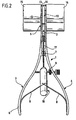
- the instrument 1 shown in FIGS. 1 to 3 for inserting an intervertebral implant 2 is according to Formed like a pair of pliers and comprises two arms 3, 4, which are essentially the same. Every arm has a flat guide body 5 and one itself subsequent, from the plane of the guide body 5 laterally emerging handle part 6, both arms 3, 4 are in the transition area between the guide bodies 5 and the handle parts 6 by a swivel 7 such pivotally connected to each other that when pressing against each other the handle parts 6, the guide body 5 pivoted apart become.
- Spring elements 8 are arranged between the handle parts 6, that spread the handle parts 6 apart, also one of the handle parts 6 is driven by a spindle 9 interspersed that towards more or less deeply the other handle part 6 can be screwed in and forms a stop with which the approximation of the two handle parts 6 can be limited.
- the two guide bodies 5 are U-shaped in cross section trained and have opposite one another flat guide surface 10 and this laterally delimiting, extending over the entire length of the guide surface 10, towards the other guide body protruding side walls 11, which also with guide bodies approximated to one another to a maximum 5 a slot-shaped space 12 between them comply ( Figure 2). Form the two guide bodies 5 thus a guideway between them, which at the Top and bottom through the two guide surfaces 10 is limited on the sides by the Sidewalls 11.
- the guide body 5 are in the through the guide surface 10 spanned plane curved, for example this arch extends over an angle of 90 °, so that the guideway is also curved is ( Figure 1).
- the guideway can be at their Swivel joint 7 near the end laterally from the guide bodies 5 emerge, so that at this point Intervertebral implant 2 inserted into the guideway can be ( Figure 1).
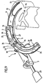
- the described implant 1 with the guide bodies 5 through body access to the intervertebral space 14 inserted between two adjacent vertebral bodies 15, in such a way that the tine-shaped extensions 13 enter the intervertebral space from the side, directly adjacent to the spinal canal 16 and ventral to this.
- the guide surfaces 10 end shortly after entering the intervertebral space 14, while the tine-shaped extensions 13 completely extend into the intervertebral space 14.
- the guide body 5 After inserting the extensions 13 into the intervertebral space 14, the guide body 5 by means of the handle parts 6 spread apart, so that thereby the distance between the vertebral bodies 15 is also increased, that is, the intervertebral space 14 is widened.
- An intervertebral implant to be inserted into the intervertebral space 14 for example the shape can have an elongated plate, is then along the Guideway formed by the guide body 5 is inserted into the intervertebral space 14.
- the plate-shaped intervertebral implant 2 with the thin flexible shaft 17 one Inserted instrument 18 connected, for example by Screwing the flexible shaft 17 into an internal thread of the intervertebral implant.
- the intervertebral implant is made by means of this insertion instrument 18 2 shifted so far along the guideway, until it is in the intervertebral space 14 between the prong-shaped extensions 13 is located reached the end of the guideway.
- the advancement is easily possible because the adjacent vertebrae 15 by the guide body 5 at a sufficient distance being held.
- the intervertebral implant 2 Once the intervertebral implant 2 is in its position reached between the prong-shaped extensions 13 it falls out of the guideway through the guiding body 5 is formed out and puts on the adjacent vertebrae. The surgeon can now press the handle parts 6 of the instrument 1 decrease and thus the expansion of the intervertebral space 14 end so that the vertebral bodies 15 move against each other and on both sides of the intervertebral implant 2 come to the plant. The instrument 1 can then easily again from the intervertebral space 14 and pulled out of the body become.
- the shaft 17 of the insertion instrument 18 is not essential must be arranged along the guideway, but can emerge from the side of the guideway since the Shaft 17 through the space 12 between the guide bodies 5 passes through.
- the insertion instrument 18 can also be removed again, for example by unscrewing the shaft 17 from the screw thread.
- intervertebral implant 2 can contain bone material from the intervertebral implant 2 unfilled part of the intervertebral space 14 and possibly in openings 19 of the intervertebral implant 2 are filled.
- a filling instrument 20 take place, which includes a filler tube 21, in the Bone material can be filled.
- a Ram 22 can remove the bone material from the fill tube 21 are pushed out at its free end.
- this filler tube 21 at the described Filling channel of the intervertebral implant 2 bone material passes through this filler channel and passes into the openings 19 of the intervertebral implant 2 and through the entire intervertebral implant 2 into the ventral part of the intervertebral implant 2 arranged part of the intervertebral space 14, so that the intervertebral implant 2 very is effectively encased in bone.
- the shape of the intervertebral implant 2 can be in this Traps to be quite different.
- an intervertebral implant 2 which is elongated and light is curved, being in the central area has a smaller width than in the end area.
- this middle area is the implant on its ventral Deepened along the long side, so that there is a recording room for bone material that arises when the intervertebral implant is inserted 2 to form-fitting embedding of the intervertebral implant 2 in the intervertebral space 14 leads.
- FIG. 6 instead of one Intervertebral implant 2 two intervertebral implants 2 inserted at a distance from each other, this insertion takes place in sequential insertion processes exactly in the same way as the implant of Figures 1 to 3 has been described.
- the Implants 2 of FIG. 6 essentially have one oval or elliptical cross section, in the embodiment of Figure 7 are essentially two implants rectangular cross section provided, too these are used in a similar way.
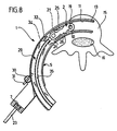
- FIGS. 8 to 11 Shown embodiment of an instrument 1, which is similar to the instrument of the figures 1 to 3, corresponding parts therefore wear the same reference numerals.
- the instrument does not have the shape of a Pliers. Rather, the two guide bodies 5 are the same connected to one another via a swivel joint 7 and end on this swivel 7, one of the two guide bodies 5 carries a handle 23. Alternatively, could also be provided one of the two branch-like To design handle parts 6 in the area of the joint 7 removable and the remaining handle part as a handle to use.
- the parts advanced between the guide bodies 5 can be easily through the intervertebral implant 2 be formed yourself, but it is advantageous if - as shown in the embodiment of Figures 8 to 11 -
- a special between the guide bodies 5 Feed body 24 slidable along the guideway is mounted, which rests on the two guide bodies 5 and doing this spreading.
- the feed body 24 is elongated and rests on both sides the side walls 11 of the guide body 5 so that it is guided exactly along the guideway. He points an elongated receiving space 25, which by the im essentially parallel side walls 26 of the feed body 24 is formed and on the top and bottom and in Feed direction front end is open.
- this receiving space 25 is from the open side forth the intervertebral implant 2 between the side walls 26 inserted and in the inserted position held by elastic locking tongues 27 which in the side walls 26 of the feed body 24 are incorporated are and the elastic in side recesses 28 of the Intervene intervertebral implant 2 ( Figure 11).
- the height of the intervertebral implant 2 equal to the height of the feed body 24, in this case spread intervertebral implant and feed body together the guide body 5 on when along the Guide path are advanced.
- the intervertebral implant could also have a slightly smaller height than the feed body, in which case the Spreading only through the feed body respectively.
- the feed body 24 is connected to a curved one Rack 29, which in one of the two guide bodies 5th is guided and which meshes with a gear 30, the one of the guide bodies 5 is rotatably supported and is rotatable via a rotary handle 31, so that the Rack 29 pushed back and forth along the guideway can be.
- the connection between the feed body 24 and rack 29 is detachable, in the illustrated
- the feed body carries the exemplary embodiment 24 vertically on two projecting tabs 32 each protruding pin 33 which in a bore 34 at the end the rack 29 can be inserted.
- the intervertebral implant 2 To insert the intervertebral implant 2, this is inserted into the receiving space 25 until the locking tongues Snap 27 into the recesses 28.
- the feed body 24 can then on the insertion side between the guide body 5 inserted and inserted the pins 33 into the bores 34 with the rack 29 are also connected between the guide body is partially inserted.
- the rack 29 advanced between the guide bodies and thereby pushes the feed body 24 with the intervertebral implant 2 gradually into the intervertebral space 14 in front of that by spreading the guide body 5 is expanded during this feed movement.
- the intervertebral implant 2 is in the end position located in the intervertebral space 14, that is Retaining element 36 is inserted until it is on the intervertebral implant 2 comes to the plant.
- the insertion depth of the retaining element 36 can by a stop be limited, for example by a lateral bend 38 of the retaining element 36 is formed that strikes the guide body 5 ( Figure 11).
- the retention element 36 via not shown in the drawing Means on the guide body 5 releasably fixable.
Description
- Figur 1:
- Eine Draufsicht auf ein chirurgisches Führungs- und Spreizinstrument mit längs der Führungsbahn mittels eines Einsetzinstruments vorgeschobenem Zwischenwirbelimplantat;
- Figur 2:
- eine Seitenansicht in Richtung des Pfeils A in Figur 1;
- Figur 3:
- eine perspektivische Ansicht des in den Zwischenwirbelraums eingesetzten chirurgischen Instruments mit dem Zwischenwirbelimplantat in der Endposition im Zwischenwirbelraum;
- Figur 4:
- eine perspektivische Ansicht eines Zwischenwirbelimplantats im Zwischenwirbelraum mit eingesetzter Vorrichtung zum Einfüllen von Knochenmaterial;
- Figur 5:
- eine Draufsicht auf ein erstes bevorzugtes Ausführungsbeispiel eines Zwischenwirbelimplantats mit gebogenen Längsseiten am Ende des chirurgischen Einführinstruments;
- Figur 6:
- eine Ansicht ähnlich Figur 5 mit zwei nebeneinander eingesetzten Zwischenwirbelimplantaten am Ende des chirurgischen Einführelements;
- Figur 7:
- eine Ansicht ähnlich Figur 6 bei Zwischenwirbelimplantaten mit rechteckigem Querschnitt;
- Figur 8:
- eine Draufsicht auf eine weitere bevorzugte Ausführungsform eines chirurgischen Führungs- und Spreizinstrumentes bei abgenommenem oberen Führungskörper;
- Figur 9:
- eine perspektivische Ansicht des Instruments der Figur 8 mit abgenommenem oberen Führungskörper;
- Figur 10:
- eine Ansicht ähnlich Figur 9 mit aufgesetztem oberen Führungskörper und eingeschobenem Rückhalteelement und
- Figur 11:
- eine Ansicht ähnlich Figur 8 mit vollständig eingeschobenem Vorschubkörper und vollständig eingeschobenem Rückhalteelement.
Claims (24)
- Chirurgisches Instrument zum Einführen von Zwischenwirbelimplantaten (2) in den Zwischenwirbelraum (14) zwischen benachbarten Wirbelkörpern (15) mit zwei einander gegenüberliegenden Führungskörpern (5) mit einer zum jeweils anderen Führungskörper (5) gerichteten Führung (10, 11), die gemeinsam eine Führungsbahn zwischen sich ausbilden, längs der ein Zwischenwirbelimplantat (2) seitlich in den Zwischenwirbelraum (14) einschiebbar ist, dadurch gekennzeichnet, daß die Führungskörper (5) in ihrem gegenseitigen Abstand verstellbar sind.
- Chirurgisches Instrument nach Anspruch 1, dadurch gekennzeichnet, daß die Führungsbahn in der Verschiebeebene bogenförmig verläuft.
- Chirurgisches Instrument nach einem der voranstehenden Ansprüche, dadurch gekennzeichnet, daß der Zwischenraum zwischen den Führungskörpern (5) zumindest einseitig längs der Führungsbahn offen ist.
- Chirurgisches Instrument nach einem der voranstehenden Ansprüche, dadurch gekennzeichnet, daß die Führungskörper (5) ein freies Ende aufweisen und dort Verlängerungen (13) tragen, die an den Zwischenwirbelraum (14) bildenden Wirbelkörpern (15) anlegbar sind und die so neben der Führungsbahn angeordnet sind, daß das längs der Führungsbahn vorgeschobene Zwischenwirbelimplantat (2) am Ende der Führungsbahn neben der Verlängerung (13) an die benachbarten Wirbelkörper (15) anlegbar ist.
- Chirurgisches Instrument nach Anspruch 4, dadurch gekennzeichnet, daß die Verlängerungen (13) als paarweise in Verschieberichtung vom Ende der Führungsbahn in dessen Fortsetzung vorstehende Zinken ausgebildet sind.
- Chirurgisches Instrument nach einem der voranstehenden Ansprüche, dadurch gekennzeichnet, daß die Führungsbahn an der Oberseite und an der Unterseite durch zwei Führungsflächen (10) begrenzt wird und an den Seiten durch Seitenwände (11), die einen schlitzförmigen Zwischenraum (12) zwischen sich einhalten, so daß ein zwischen den Führungskörpern (5) geführtes Zwischenwirbelimplantat (2) in der Führungsbahn auch dann geführt ist, wenn der Abstand der Führungskörper (50) sich vergrößert.
- Chirurgisches Instrument nach einem der voranstehenden Ansprüche, dadurch gekennzeichnet, daß die Führungskörper (5) ein freies Ende aufweisen und an dem dem freien Ende gegenüberliegenden Ende (7) schwenkbar miteinander verbunden sind.
- Chirurgisches Instrument nach einem der voranstehenden Ansprüche, dadurch gekennzeichnet, daß jeder Führungskörper (5) eine ebene Anlagefläche (10) für das Zwischenwirbelimplantat (2) und diese seitlich begrenzende, parallel zueinander längs des Führungskörpers (5) verlaufende Führungswände (11) aufweist, die in Richtung auf den anderen Führungskörper (5) über die Anlagefläche (10) vorstehen.
- Chirurgisches Instrument nach einem der voranstehenden Ansprüche, dadurch gekennzeichnet, daß die Führungskörper (5) ein freies Ende aufweisen und daß die Führungsbahn an ihrem dem freien Ende der Führungskörper (5) gegenüberliegenden Ende seitlich aus dem Instrument austritt, so daß dort ein Zwischenwirbelimplantat (2) in die Führungsbahn einschiebbar ist.
- Chirurgisches Instrument nach einem der Ansprüche 7 bis 9, dadurch gekennzeichnet, daß beide Führungskörper (5) mit Griffbranchen (6) fest verbunden sind, die sich über die gelenkige Verbindungsstelle (7) der Führungskörper (5) hinaus erstrecken.
- Chirurgisches Instrument nach einem der voranstehenden Ansprüche, dadurch gekennzeichnet, daß an ihm ein Anschlag (9) zur Einhaltung eines Mindestabstands zwischen den beiden Führungskörpern (5) angeordnet ist.
- Chirurgisches Instrument nach Anspruch 11, dadurch gekennzeichnet, daß der Anschlag (9) verstellbar ist.
- Chirurgisches Instrument nach einem der voranstehenden Ansprüche, dadurch gekennzeichnet, daß zwischen den beiden Führungskörpern (5) längs der von diesen gebildeten Führungsbahn ein Vorschubkörper (24) verschiebbar gelagert ist, der eine lösbare Halterung für das Zwischenwirbalimplantat (2) aufweist.
- Chirurgisches Instrument nach Anspruch 13, dadurch gekennzeichnet, daß der Vorschubkörper (24) einen zu seinem in Vorschubrichtung vorderen Ende hin offenen Aufnahmeraum (25) für das Zwischenwirbelimplantat (2) aufweist.
- Chirurgisches Instrument nach Anspruch 14, dadurch gekennzeichnet, daß der Aufnahmeraum (25) durch zwei längs der Führungsbahn verlaufende Seitenwände (26) begrenzt wird.
- Chirurgisches Instrument nach einem der Ansprüche 13 bis 15, dadurch gekennzeichnet, daß die lösbare Halterung elastische Rasten (27) umfaßt, die in Rücksprünge d(28) einfedern.
- Chirurgisches Instrument nach einem der Ansprüche 14 bis 16, dadurch gekennzeichnet, daß der Vorschubkörper (24) an seinem in Vorschubrichtung hinteren Ende eine Zugangsöffnung (37) für ein an dem Zwischenwirbelimplantat (2) anlegbares Rückhalteelement (36) aufweist.
- Chirurgisches Instrument nach Anspruch 17, dadurch gekennzeichnet, daß das Rückhalteelement (36) entsprechend der Führungsbahn gebogen ist.
- Chirurgisches Instrument nach einem der Ansprüche 13 bis 18, dadurch gekennzeichnet, daß der Vorschubkörper (24) mit einer längs der Führungsbahn verschiebbaren, gebogenen Vorschubstange (29) verbunden ist.
- Chirurgisches Instrument nach Anspruch 19, dadurch gekennzeichnet, daß die Verbindung (33, 34) zwischen Vorschubkörper (24) und Vorschubstange (29) lösbar ist.
- Chirurgisches Instrument nach Anspruch 19 oder 20, dadurch gekennzeichnet, daß die Vorschubstange (29) als Zahnstange ausgebildet ist, welche mit einem an einem Führungskörper (5) drehbar gelagerten Zahnrad (30) kämmt.
- Chirurgisches Instrument nach einem der Ansprüche 19 bis 21, dadurch gekennzeichnet, daß die Vorschubstange (29) eine Längsnut (35) zur Aufnahme und Führung eines Rückhalteelementes (36) für das Zwischenwirbelimplantat aufweist.
- Chirurgisches Instrument nach einem der Ansprüche 7 bis 22 und durch dieses in einen Zwischenwirbelraum einschiebbares Zwischenwirbelimplantat (2), dadurch gekennzeichnet, daß die Führungskörper (5) von ihrer Schwenklagerstelle (7) bis zu ihrem freien Ende hin einen abnehmenden Abstand zueinander aufweisen, der an der in Vorschubrichtung hinten angeordneten Einschubseite der Führungsbahn größer ist als die Höhe des Zwischenwirbelimplantates und gegebenenfalls des Vorschubkörpers (24), an der in Vorschubrichtung vorne liegenden Austrittsseite der Führungsbahn jedoch kleiner als die Höhe des Zwischenwirbelimplantates und/oder des Vorschubkörpers (24).
- Chirurgisches Instrument nach Anspruch 23, dadurch gekennzeichnet, daß der Vorschubkörper (24) und/oder die Führungskörper (5) an den aneinander anliegenden Flächen aus einem reibungsarmen Material bestehen.
Applications Claiming Priority (4)
| Application Number | Priority Date | Filing Date | Title |
|---|---|---|---|
| DE19903762A DE19903762C1 (de) | 1999-01-30 | 1999-01-30 | Chirurgisches Instrument zum Einführen von Zwischenwirbelimplantaten |
| DE29901611U DE29901611U1 (de) | 1999-01-30 | 1999-01-30 | Chirurgisches Instrument zum Einführen von Zwischenwirbelimplantaten |
| DE19903762 | 1999-01-30 | ||
| PCT/EP2000/000625 WO2000044288A1 (de) | 1999-01-30 | 2000-01-27 | Chirurgisches instrument zum einführen von zwischenwirbelimplantaten |
Publications (2)
| Publication Number | Publication Date |
|---|---|
| EP1146821A1 EP1146821A1 (de) | 2001-10-24 |
| EP1146821B1 true EP1146821B1 (de) | 2003-11-05 |
Family
ID=26051598
Family Applications (1)
| Application Number | Title | Priority Date | Filing Date |
|---|---|---|---|
| EP00902636A Expired - Lifetime EP1146821B1 (de) | 1999-01-30 | 2000-01-27 | Chirurgisches instrument zum einführen von zwischenwirbelimplantaten |
Country Status (7)
| Country | Link |
|---|---|
| US (1) | US6599294B2 (de) |
| EP (1) | EP1146821B1 (de) |
| JP (1) | JP3550094B2 (de) |
| AT (1) | ATE253325T1 (de) |
| DE (2) | DE19903762C1 (de) |
| ES (1) | ES2209811T3 (de) |
| WO (1) | WO2000044288A1 (de) |
Cited By (1)
| Publication number | Priority date | Publication date | Assignee | Title |
|---|---|---|---|---|
| US9011450B2 (en) | 2012-08-08 | 2015-04-21 | DePuy Synthes Products, LLC | Surgical instrument |
Families Citing this family (308)
| Publication number | Priority date | Publication date | Assignee | Title |
|---|---|---|---|---|
| DE19903762C1 (de) * | 1999-01-30 | 2000-11-16 | Aesculap Ag & Co Kg | Chirurgisches Instrument zum Einführen von Zwischenwirbelimplantaten |
| EP1253854A4 (de) * | 1999-03-07 | 2010-01-06 | Discure Ltd | Verfahren und vorrichtung für computerisierte chirurgie |
| US6159179A (en) | 1999-03-12 | 2000-12-12 | Simonson; Robert E. | Cannula and sizing and insertion method |
| ATE388677T1 (de) | 1999-07-02 | 2008-03-15 | Spine Solutions Inc | Zwischenwirbelimplantat |
| US6821276B2 (en) | 1999-08-18 | 2004-11-23 | Intrinsic Therapeutics, Inc. | Intervertebral diagnostic and manipulation device |
| US7717961B2 (en) | 1999-08-18 | 2010-05-18 | Intrinsic Therapeutics, Inc. | Apparatus delivery in an intervertebral disc |
| US8323341B2 (en) | 2007-09-07 | 2012-12-04 | Intrinsic Therapeutics, Inc. | Impaction grafting for vertebral fusion |
| US6936072B2 (en) | 1999-08-18 | 2005-08-30 | Intrinsic Therapeutics, Inc. | Encapsulated intervertebral disc prosthesis and methods of manufacture |
| JP4247519B2 (ja) | 1999-08-18 | 2009-04-02 | イントリンジック セラピューティックス インコーポレイテッド | 髄核オーグメンテーションおよび保定のための装置および方法 |
| US7972337B2 (en) | 2005-12-28 | 2011-07-05 | Intrinsic Therapeutics, Inc. | Devices and methods for bone anchoring |
| DE59914213D1 (de) | 1999-09-14 | 2007-04-05 | Spine Solutions Inc | Einsetzinstrument für ein zwischenwirbelimplantat |
| US6530929B1 (en) | 1999-10-20 | 2003-03-11 | Sdgi Holdings, Inc. | Instruments for stabilization of bony structures |
| US6764491B2 (en) | 1999-10-21 | 2004-07-20 | Sdgi Holdings, Inc. | Devices and techniques for a posterior lateral disc space approach |
| WO2001028469A2 (en) | 1999-10-21 | 2001-04-26 | Sdgi Holdings, Inc. | Devices and techniques for a posterior lateral disc space approach |
| US6830570B1 (en) | 1999-10-21 | 2004-12-14 | Sdgi Holdings, Inc. | Devices and techniques for a posterior lateral disc space approach |
| US7470236B1 (en) | 1999-11-24 | 2008-12-30 | Nuvasive, Inc. | Electromyography system |
| ATE270848T1 (de) * | 2000-02-22 | 2004-07-15 | Sdgi Holdings Inc | Besteck zur vorbereitung des zwischenwirbelraums |
| US6478800B1 (en) | 2000-05-08 | 2002-11-12 | Depuy Acromed, Inc. | Medical installation tool |
| US6579318B2 (en) * | 2000-06-12 | 2003-06-17 | Ortho Development Corporation | Intervertebral spacer |
| CA2414168C (en) * | 2000-06-23 | 2010-02-09 | University Of Southern California | Percutaneous vertebral fusion system |
| US6964667B2 (en) * | 2000-06-23 | 2005-11-15 | Sdgi Holdings, Inc. | Formed in place fixation system with thermal acceleration |
| US6899713B2 (en) * | 2000-06-23 | 2005-05-31 | Vertelink Corporation | Formable orthopedic fixation system |
| US6875212B2 (en) * | 2000-06-23 | 2005-04-05 | Vertelink Corporation | Curable media for implantable medical device |
| US6749614B2 (en) | 2000-06-23 | 2004-06-15 | Vertelink Corporation | Formable orthopedic fixation system with cross linking |
| US7204851B2 (en) * | 2000-08-30 | 2007-04-17 | Sdgi Holdings, Inc. | Method and apparatus for delivering an intervertebral disc implant |
| US6673113B2 (en) | 2001-10-18 | 2004-01-06 | Spinecore, Inc. | Intervertebral spacer device having arch shaped spring elements |
| US7235081B2 (en) * | 2001-07-16 | 2007-06-26 | Spinecore, Inc. | Wedge plate inserter/impactor and related methods for use in implanting an artificial intervertebral disc |
| US7169182B2 (en) * | 2001-07-16 | 2007-01-30 | Spinecore, Inc. | Implanting an artificial intervertebral disc |
| WO2002069811A1 (en) * | 2001-03-02 | 2002-09-12 | Osteotech, Inc. | Vertebral distractor |
| FR2824261B1 (fr) * | 2001-05-04 | 2004-05-28 | Ldr Medical | Prothese de disque intervertebral et procede et outils de mise en place |
| US8353932B2 (en) | 2005-09-30 | 2013-01-15 | Jackson Roger P | Polyaxial bone anchor assembly with one-piece closure, pressure insert and plastic elongate member |
| US8292926B2 (en) | 2005-09-30 | 2012-10-23 | Jackson Roger P | Dynamic stabilization connecting member with elastic core and outer sleeve |
| US10258382B2 (en) | 2007-01-18 | 2019-04-16 | Roger P. Jackson | Rod-cord dynamic connection assemblies with slidable bone anchor attachment members along the cord |
| US10729469B2 (en) | 2006-01-09 | 2020-08-04 | Roger P. Jackson | Flexible spinal stabilization assembly with spacer having off-axis core member |
| US7862587B2 (en) | 2004-02-27 | 2011-01-04 | Jackson Roger P | Dynamic stabilization assemblies, tool set and method |
| EP1417000B1 (de) | 2001-07-11 | 2018-07-11 | Nuvasive, Inc. | System zur bestimmung von nervenproximität während operationen |
| JP2005503857A (ja) | 2001-09-25 | 2005-02-10 | ヌバシブ, インコーポレイテッド | 外科処置手順および外科的診断を実施するためのシステムおよび方法 |
| DE20116410U1 (de) * | 2001-09-26 | 2001-11-29 | Aesculap Ag & Co Kg | Chirurgisches Instrument |
| WO2003026538A1 (en) * | 2001-09-27 | 2003-04-03 | Sulzer Spine-Tech Inc. | Modular spinal fusion device |
| US7771477B2 (en) | 2001-10-01 | 2010-08-10 | Spinecore, Inc. | Intervertebral spacer device utilizing a belleville washer having radially spaced concentric grooves |
| US7713302B2 (en) * | 2001-10-01 | 2010-05-11 | Spinecore, Inc. | Intervertebral spacer device utilizing a spirally slotted belleville washer having radially spaced concentric grooves |
| CA2460028A1 (en) * | 2001-10-30 | 2003-05-08 | Osteotech, Inc. | Bone implant and insertion tools |
| US7008431B2 (en) * | 2001-10-30 | 2006-03-07 | Depuy Spine, Inc. | Configured and sized cannula |
| US6916330B2 (en) * | 2001-10-30 | 2005-07-12 | Depuy Spine, Inc. | Non cannulated dilators |
| US7824410B2 (en) * | 2001-10-30 | 2010-11-02 | Depuy Spine, Inc. | Instruments and methods for minimally invasive spine surgery |
| US8038713B2 (en) | 2002-04-23 | 2011-10-18 | Spinecore, Inc. | Two-component artificial disc replacements |
| US20080027548A9 (en) | 2002-04-12 | 2008-01-31 | Ferree Bret A | Spacerless artificial disc replacements |
| US7582058B1 (en) | 2002-06-26 | 2009-09-01 | Nuvasive, Inc. | Surgical access system and related methods |
| US6793678B2 (en) | 2002-06-27 | 2004-09-21 | Depuy Acromed, Inc. | Prosthetic intervertebral motion disc having dampening |
| WO2004016217A2 (en) | 2002-08-15 | 2004-02-26 | David Gerber | Controlled artificial intervertebral disc implant |
| DE20321571U1 (de) * | 2002-08-15 | 2008-02-14 | Synthes Gmbh | Bandscheibenimplantat |
| GB0221527D0 (en) * | 2002-09-17 | 2002-10-23 | Depuy Int Ltd | Spinal implantation device |
| EP2002805A3 (de) | 2002-09-19 | 2009-01-07 | Malan De Villiers | Zwischenwirbelprothese |
| JP2006501947A (ja) * | 2002-10-08 | 2006-01-19 | エスディージーアイ・ホールディングス・インコーポレーテッド | 整形外科移植片の挿入装置と技法 |
| US8137284B2 (en) | 2002-10-08 | 2012-03-20 | Nuvasive, Inc. | Surgical access system and related methods |
| US7204852B2 (en) | 2002-12-13 | 2007-04-17 | Spine Solutions, Inc. | Intervertebral implant, insertion tool and method of inserting same |
| US7691057B2 (en) | 2003-01-16 | 2010-04-06 | Nuvasive, Inc. | Surgical access system and related methods |
| EP2329778A3 (de) * | 2003-01-31 | 2012-06-20 | Spinalmotion, Inc. | Anzeige für die Wirbelsäulenmittellinie |
| JP4275699B2 (ja) | 2003-01-31 | 2009-06-10 | スパイナルモーション, インコーポレイテッド | 椎骨間プロテーゼ配置器具 |
| AU2004212942A1 (en) | 2003-02-14 | 2004-09-02 | Depuy Spine, Inc. | In-situ formed intervertebral fusion device |
| US7819801B2 (en) | 2003-02-27 | 2010-10-26 | Nuvasive, Inc. | Surgical access system and related methods |
| US6908484B2 (en) | 2003-03-06 | 2005-06-21 | Spinecore, Inc. | Cervical disc replacement |
| JP2006521899A (ja) * | 2003-03-31 | 2006-09-28 | デピュイ・スパイン・インコーポレイテッド | 人工椎間板を挿入するための方法及び装置 |
| KR100849292B1 (ko) * | 2003-03-31 | 2008-07-29 | 샤프 가부시키가이샤 | 액정 표시 장치 및 그 제조 방법 |
| US7563281B2 (en) | 2003-04-03 | 2009-07-21 | Warsaw Orthopedic, Inc. | Apparatus and method for supporting vertebral bodies |
| US7621918B2 (en) * | 2004-11-23 | 2009-11-24 | Jackson Roger P | Spinal fixation tool set and method |
| US7491204B2 (en) | 2003-04-28 | 2009-02-17 | Spine Solutions, Inc. | Instruments and method for preparing an intervertebral space for receiving an artificial disc implant |
| US8262571B2 (en) | 2003-05-22 | 2012-09-11 | Stephen Ritland | Intermuscular guide for retractor insertion and method of use |
| US10052211B2 (en) | 2003-05-27 | 2018-08-21 | Simplify Medical Pty Ltd. | Prosthetic disc for intervertebral insertion |
| US20090076614A1 (en) * | 2007-09-17 | 2009-03-19 | Spinalmotion, Inc. | Intervertebral Prosthetic Disc with Shock Absorption Core |
| US7575599B2 (en) | 2004-07-30 | 2009-08-18 | Spinalmotion, Inc. | Intervertebral prosthetic disc with metallic core |
| EP2226038A1 (de) | 2003-05-27 | 2010-09-08 | Spinalmotion, Inc. | Prothesescheibe für einen Bandscheibeneinsatz |
| US7766915B2 (en) | 2004-02-27 | 2010-08-03 | Jackson Roger P | Dynamic fixation assemblies with inner core and outer coil-like member |
| US7776067B2 (en) | 2005-05-27 | 2010-08-17 | Jackson Roger P | Polyaxial bone screw with shank articulation pressure insert and method |
| US20040267367A1 (en) | 2003-06-30 | 2004-12-30 | Depuy Acromed, Inc | Intervertebral implant with conformable endplate |
| US7803162B2 (en) | 2003-07-21 | 2010-09-28 | Spine Solutions, Inc. | Instruments and method for inserting an intervertebral implant |
| US7806932B2 (en) | 2003-08-01 | 2010-10-05 | Zimmer Spine, Inc. | Spinal implant |
| US20060229627A1 (en) * | 2004-10-29 | 2006-10-12 | Hunt Margaret M | Variable angle spinal surgery instrument |
| US7252673B2 (en) * | 2003-09-10 | 2007-08-07 | Warsaw Orthopedic, Inc. | Devices and methods for inserting spinal implants |
| US8002798B2 (en) | 2003-09-24 | 2011-08-23 | Stryker Spine | System and method for spinal implant placement |
| US7955355B2 (en) | 2003-09-24 | 2011-06-07 | Stryker Spine | Methods and devices for improving percutaneous access in minimally invasive surgeries |
| WO2005030318A1 (en) | 2003-09-25 | 2005-04-07 | Nuvasive, Inc. | Surgical access system and related methods |
| US7905840B2 (en) | 2003-10-17 | 2011-03-15 | Nuvasive, Inc. | Surgical access system and related methods |
| US7455685B2 (en) | 2003-09-29 | 2008-11-25 | Warsaw Orthopedic, Inc. | Instruments and methods for securing a connecting element along a bony segment |
| US20050124999A1 (en) * | 2003-10-31 | 2005-06-09 | Teitelbaum George P. | Device and method for radial delivery of a structural element |
| US7341587B2 (en) * | 2003-11-20 | 2008-03-11 | Warsaw Orthopedic, Inc. | Methods and devices for inserting and engaging vertebral implants in minimally invasive procedures |
| US20050154462A1 (en) * | 2003-12-02 | 2005-07-14 | St. Francis Medical Technologies, Inc. | Laterally insertable artificial vertebral disk replacement implant with translating pivot point |
| US7179261B2 (en) | 2003-12-16 | 2007-02-20 | Depuy Spine, Inc. | Percutaneous access devices and bone anchor assemblies |
| US7527638B2 (en) | 2003-12-16 | 2009-05-05 | Depuy Spine, Inc. | Methods and devices for minimally invasive spinal fixation element placement |
| US11419642B2 (en) | 2003-12-16 | 2022-08-23 | Medos International Sarl | Percutaneous access devices and bone anchor assemblies |
| AU2004304934B2 (en) * | 2003-12-16 | 2008-10-16 | Depuy Spine, Inc. | Methods and devices for minimally invasive spinal fixation element placement |
| US8123757B2 (en) * | 2003-12-31 | 2012-02-28 | Depuy Spine, Inc. | Inserter instrument and implant clip |
| US7108698B2 (en) * | 2004-01-13 | 2006-09-19 | Zimmer Spine, Inc. | Combined distractor and retractor instrument and methods |
| WO2005077288A1 (en) * | 2004-02-09 | 2005-08-25 | Depuy Spine, Inc. | Systems and methods for spinal surgery |
| US8152810B2 (en) * | 2004-11-23 | 2012-04-10 | Jackson Roger P | Spinal fixation tool set and method |
| US7470279B2 (en) * | 2004-02-27 | 2008-12-30 | Jackson Roger P | Orthopedic implant rod reduction tool set and method |
| WO2005092218A1 (en) | 2004-02-27 | 2005-10-06 | Jackson Roger P | Orthopedic implant rod reduction tool set and method |
| US7160300B2 (en) | 2004-02-27 | 2007-01-09 | Jackson Roger P | Orthopedic implant rod reduction tool set and method |
| US7918891B1 (en) | 2004-03-29 | 2011-04-05 | Nuvasive Inc. | Systems and methods for spinal fusion |
| FR2869528B1 (fr) | 2004-04-28 | 2007-02-02 | Ldr Medical | Prothese de disque intervertebral |
| US7578834B2 (en) * | 2004-05-03 | 2009-08-25 | Abdou M S | Devices and methods for the preservation of spinal prosthesis function |
| US7854766B2 (en) | 2004-05-13 | 2010-12-21 | Moskowitz Nathan C | Artificial total lumbar disc for unilateral safe and simple posterior placement in the lumbar spine, and removable bifunctional screw which drives vertical sliding expansile plate expansion, and interplate widening, and angled traction spikes |
| US20050261692A1 (en) * | 2004-05-21 | 2005-11-24 | Scimed Life Systems, Inc. | Articulating tissue removal probe and methods of using the same |
| FR2871366A1 (fr) | 2004-06-09 | 2005-12-16 | Ceravic Soc Par Actions Simpli | Implant expansible prothetique osseux |
| US8753348B2 (en) | 2004-07-02 | 2014-06-17 | DePuy Synthes Products, LLC | Compressor-distractor |
| US7625380B2 (en) * | 2004-07-21 | 2009-12-01 | Warsaw Orthopedic, Inc. | Dual distractor inserter |
| US7585326B2 (en) | 2004-08-06 | 2009-09-08 | Spinalmotion, Inc. | Methods and apparatus for intervertebral disc prosthesis insertion |
| US8236029B2 (en) * | 2004-08-11 | 2012-08-07 | Nlt Spine Ltd. | Devices for introduction into a body via a substantially straight conduit to for a predefined curved configuration, and methods employing such devices |
| US7465306B2 (en) | 2004-08-13 | 2008-12-16 | Warsaw Orthopedic, Inc. | System and method for positioning a connecting member adjacent the spinal column in minimally invasive procedures |
| US7641690B2 (en) | 2004-08-23 | 2010-01-05 | Abdou M Samy | Bone fixation and fusion device |
| JP2006068086A (ja) * | 2004-08-31 | 2006-03-16 | Takiron Co Ltd | 人工椎間板挿入治具及び治具セット |
| US7547309B2 (en) * | 2004-09-23 | 2009-06-16 | Spine Solutions, Inc. | Distractor for lumbar insertion instrument |
| US7651502B2 (en) * | 2004-09-24 | 2010-01-26 | Jackson Roger P | Spinal fixation tool set and method for rod reduction and fastener insertion |
| US8298235B2 (en) * | 2004-09-30 | 2012-10-30 | Depuy Spine, Inc. | Instrument and method for the insertion and alignment of an intervertebral implant |
| US7951153B2 (en) | 2004-10-05 | 2011-05-31 | Samy Abdou | Devices and methods for inter-vertebral orthopedic device placement |
| WO2006042241A2 (en) | 2004-10-08 | 2006-04-20 | Nuvasive, Inc. | Surgical access system and related methods |
| CA2614133A1 (en) * | 2004-10-25 | 2006-05-04 | Lanx, Llc | Interspinous distraction devices and associated methods of insertion |
| US7918875B2 (en) * | 2004-10-25 | 2011-04-05 | Lanx, Inc. | Interspinous distraction devices and associated methods of insertion |
| US8241330B2 (en) | 2007-01-11 | 2012-08-14 | Lanx, Inc. | Spinous process implants and associated methods |
| US9055981B2 (en) | 2004-10-25 | 2015-06-16 | Lanx, Inc. | Spinal implants and methods |
| US9216041B2 (en) | 2009-06-15 | 2015-12-22 | Roger P. Jackson | Spinal connecting members with tensioned cords and rigid sleeves for engaging compression inserts |
| US9393047B2 (en) | 2009-06-15 | 2016-07-19 | Roger P. Jackson | Polyaxial bone anchor with pop-on shank and friction fit retainer with low profile edge lock |
| WO2006057837A1 (en) | 2004-11-23 | 2006-06-01 | Jackson Roger P | Spinal fixation tool attachment structure |
| ATE524121T1 (de) | 2004-11-24 | 2011-09-15 | Abdou Samy | Vorrichtungen zur platzierung eines orthopädischen intervertebralen implantats |
| WO2006066228A2 (en) * | 2004-12-16 | 2006-06-22 | Innovative Spinal Technologies | Expandable implants for spinal disc replacement |
| US7625376B2 (en) * | 2005-01-26 | 2009-12-01 | Warsaw Orthopedic, Inc. | Reducing instrument for spinal surgery |
| US8083797B2 (en) | 2005-02-04 | 2011-12-27 | Spinalmotion, Inc. | Intervertebral prosthetic disc with shock absorption |
| US8911498B2 (en) * | 2005-02-10 | 2014-12-16 | DePuy Synthes Products, LLC | Intervertebral prosthetic disc |
| US7690381B2 (en) * | 2005-02-10 | 2010-04-06 | Depuy Spine, Inc. | Intervertebral prosthetic disc and method for installing using a guidewire |
| US7901437B2 (en) | 2007-01-26 | 2011-03-08 | Jackson Roger P | Dynamic stabilization member with molded connection |
| US20060235279A1 (en) * | 2005-03-18 | 2006-10-19 | Hawkes David T | Less invasive access port system and method for using the same |
| US7749269B2 (en) | 2005-03-28 | 2010-07-06 | Warsaw Orthopedic, Inc. | Spinal system and method including lateral approach |
| US7763078B2 (en) | 2005-03-28 | 2010-07-27 | Warsaw Orthopedic, Inc. | Spinal device including lateral approach |
| US7959675B2 (en) * | 2005-04-08 | 2011-06-14 | G&L Consulting, Llc | Spine implant insertion device and method |
| BRPI0609358A2 (pt) * | 2005-04-11 | 2010-03-30 | Impliant Ltd | próteses de inserção espinal anterior e posterior |
| US7575580B2 (en) | 2005-04-15 | 2009-08-18 | Warsaw Orthopedic, Inc. | Instruments, implants and methods for positioning implants into a spinal disc space |
| US7491208B2 (en) | 2005-04-28 | 2009-02-17 | Warsaw Orthopedic, Inc. | Instrument and method for guiding surgical implants and instruments during surgery |
| US7708743B2 (en) * | 2005-04-29 | 2010-05-04 | Warsaw Orthopedic, Inc. | Apparatus and method for positioning an implant during surgery |
| US20060247655A1 (en) * | 2005-05-02 | 2006-11-02 | Sdgi Holdings, Inc. | Instrument to insert a prosthetic implant |
| US20060271055A1 (en) * | 2005-05-12 | 2006-11-30 | Jeffery Thramann | Spinal stabilization |
| US7828830B2 (en) * | 2005-05-12 | 2010-11-09 | Lanx, Inc. | Dynamic spinal stabilization |
| US20060271048A1 (en) * | 2005-05-12 | 2006-11-30 | Jeffery Thramann | Pedicle screw based vertebral body stabilization apparatus |
| US20080234550A1 (en) * | 2005-05-26 | 2008-09-25 | Hawkes David T | Minimally Traumatic Portal |
| US8579911B2 (en) * | 2008-01-18 | 2013-11-12 | Spinecore, Inc. | Instruments and methods for inserting artificial intervertebral implants |
| US8777959B2 (en) | 2005-05-27 | 2014-07-15 | Spinecore, Inc. | Intervertebral disc and insertion methods therefor |
| US7628800B2 (en) * | 2005-06-03 | 2009-12-08 | Warsaw Orthopedic, Inc. | Formed in place corpectomy device |
| FR2887762B1 (fr) | 2005-06-29 | 2007-10-12 | Ldr Medical Soc Par Actions Si | Instrumentation d'insertion de prothese de disque intervertebral entre des vertebres |
| US7670375B2 (en) * | 2005-08-16 | 2010-03-02 | Benvenue Medical, Inc. | Methods for limiting the movement of material introduced between layers of spinal tissue |
| US7695475B2 (en) * | 2005-08-26 | 2010-04-13 | Warsaw Orthopedic, Inc. | Instruments for minimally invasive stabilization of bony structures |
| US8882841B2 (en) * | 2005-09-16 | 2014-11-11 | Us Spine, Inc. | Steerable interbody fusion cage |
| FR2891135B1 (fr) | 2005-09-23 | 2008-09-12 | Ldr Medical Sarl | Prothese de disque intervertebral |
| JP2009509590A (ja) * | 2005-09-26 | 2009-03-12 | ウォーソー・オーソペディック・インコーポレーテッド | 椎骨間移植片 |
| US8696681B2 (en) * | 2005-09-29 | 2014-04-15 | K2M, Inc. | Adjustable interbody introducer device and method |
| US8105368B2 (en) | 2005-09-30 | 2012-01-31 | Jackson Roger P | Dynamic stabilization connecting member with slitted core and outer sleeve |
| US7909871B2 (en) * | 2005-10-03 | 2011-03-22 | Samy Abdou | Devices and methods for inter-vertebral orthopedic device placement |
| US8870920B2 (en) * | 2005-10-07 | 2014-10-28 | M. Samy Abdou | Devices and methods for inter-vertebral orthopedic device placement |
| US20070162040A1 (en) * | 2005-12-06 | 2007-07-12 | Zimmer Spine, Inc. | Spinal distraction and endplate preparation device and method |
| US7704271B2 (en) | 2005-12-19 | 2010-04-27 | Abdou M Samy | Devices and methods for inter-vertebral orthopedic device placement |
| US7988695B2 (en) | 2005-12-21 | 2011-08-02 | Theken Spine, Llc | Articulated delivery instrument |
| US20070161962A1 (en) * | 2006-01-09 | 2007-07-12 | Edie Jason A | Device and method for moving fill material to an implant |
| US7935148B2 (en) | 2006-01-09 | 2011-05-03 | Warsaw Orthopedic, Inc. | Adjustable insertion device for a vertebral implant |
| US7867279B2 (en) * | 2006-01-23 | 2011-01-11 | Depuy Spine, Inc. | Intervertebral disc prosthesis |
| US20070191861A1 (en) * | 2006-01-30 | 2007-08-16 | Sdgi Holdings, Inc. | Instruments and methods for implanting nucleus replacement material in an intervertebral disc nucleus space |
| CA2637684C (en) | 2006-02-06 | 2011-09-13 | Stryker Spine | Rod contouring apparatus and method for percutaneous pedicle screw extension |
| US8377072B2 (en) | 2006-02-06 | 2013-02-19 | Depuy Spine, Inc. | Medical device installation tool |
| US7875034B2 (en) * | 2006-03-14 | 2011-01-25 | Warsaw Orthopedic, Inc. | Spinal disc space preparation instruments and methods for interbody spinal implants |
| US8157845B2 (en) * | 2006-03-22 | 2012-04-17 | Beacon Biomedical, Llc | Pivotable vetrebral spacer |
| US9345587B2 (en) | 2006-03-22 | 2016-05-24 | Beacon Biomedical, Llc | Pivotal lateral cage and method of insertion |
| US7892239B2 (en) * | 2006-03-22 | 2011-02-22 | Beacon Biomedical, Llc | Pivotable interbody spacer system and method |
| EP1998720B1 (de) * | 2006-03-22 | 2021-05-12 | Alphaspine, Inc. | Drehbares zwischenwirbelabstandsstück |
| US7976549B2 (en) | 2006-03-23 | 2011-07-12 | Theken Spine, Llc | Instruments for delivering spinal implants |
| US20070225810A1 (en) * | 2006-03-23 | 2007-09-27 | Dennis Colleran | Flexible cage spinal implant |
| JP2009533187A (ja) | 2006-04-12 | 2009-09-17 | スパイナルモーション, インコーポレイテッド | 後方脊椎の装置および方法 |
| US7806895B2 (en) * | 2006-05-08 | 2010-10-05 | Device Evolutions Llc | Thoracic closure device and methods |
| US8303601B2 (en) | 2006-06-07 | 2012-11-06 | Stryker Spine | Collet-activated distraction wedge inserter |
| US7959564B2 (en) * | 2006-07-08 | 2011-06-14 | Stephen Ritland | Pedicle seeker and retractor, and methods of use |
| WO2008008840A2 (en) * | 2006-07-11 | 2008-01-17 | Alpinespine Llc | Selectively locking minimally traumatic access port |
| US7862618B2 (en) * | 2006-07-19 | 2011-01-04 | Warsaw Orthopedic, Inc. | Expandable vertebral body implants and methods of use |
| AU2007276755A1 (en) | 2006-07-24 | 2008-01-31 | Spine Solutions, Inc. | Intervertebral implant with keel |
| US8303630B2 (en) * | 2006-07-27 | 2012-11-06 | Samy Abdou | Devices and methods for the minimally invasive treatment of spinal stenosis |
| US20080027544A1 (en) * | 2006-07-28 | 2008-01-31 | Warsaw Orthopedic Inc. | Instruments and techniques for engaging spinal implants for insertion into a spinal space |
| CA2659024A1 (en) | 2006-07-31 | 2008-02-07 | Synthes (Usa) | Drilling/milling guide and keel cut preparation system |
| US8034110B2 (en) | 2006-07-31 | 2011-10-11 | Depuy Spine, Inc. | Spinal fusion implant |
| US8506636B2 (en) | 2006-09-08 | 2013-08-13 | Theken Spine, Llc | Offset radius lordosis |
| EP2063819B1 (de) * | 2006-09-18 | 2021-05-19 | Beacon Biomedical, LLC | Schwenkbares wirbelabstandselement |
| US8454621B2 (en) * | 2006-09-19 | 2013-06-04 | Warsaw Orthopedic, Inc. | Instruments and methods for spinal implant revision |
| US7686809B2 (en) * | 2006-09-25 | 2010-03-30 | Stryker Spine | Rod inserter and rod with reduced diameter end |
| EP2073734A1 (de) * | 2006-09-25 | 2009-07-01 | Stryker Spine | Kraftbegrenzungs-zwangsmittel |
| US20080082172A1 (en) * | 2006-09-29 | 2008-04-03 | Jackson Roger P | Interspinous process spacer |
| US8641764B2 (en) * | 2006-10-11 | 2014-02-04 | G&L Consulting, Llc | Spine implant insertion device and method |
| US8740941B2 (en) | 2006-11-10 | 2014-06-03 | Lanx, Inc. | Pedicle based spinal stabilization with adjacent vertebral body support |
| US8105382B2 (en) | 2006-12-07 | 2012-01-31 | Interventional Spine, Inc. | Intervertebral implant |
| EP2088945A4 (de) | 2006-12-08 | 2010-02-17 | Roger P Jackson | Werkzeugsystem für dynamische wirbelsäulenimplantate |
| US20080140085A1 (en) * | 2006-12-11 | 2008-06-12 | G&L Consulting, Llc | Steerable spine implant insertion device and method |
| US7875079B2 (en) | 2006-12-14 | 2011-01-25 | Warsaw Orthopedic, Inc. | Vertebral implant containment device and methods of use |
| US8480718B2 (en) * | 2006-12-21 | 2013-07-09 | Warsaw Orthopedic, Inc. | Curable orthopedic implant devices configured to be hardened after placement in vivo |
| US7771476B2 (en) | 2006-12-21 | 2010-08-10 | Warsaw Orthopedic Inc. | Curable orthopedic implant devices configured to harden after placement in vivo by application of a cure-initiating energy before insertion |
| US8663328B2 (en) * | 2006-12-21 | 2014-03-04 | Warsaw Orthopedic, Inc. | Methods for positioning a load-bearing component of an orthopedic implant device by inserting a malleable device that hardens in vivo |
| US8758407B2 (en) * | 2006-12-21 | 2014-06-24 | Warsaw Orthopedic, Inc. | Methods for positioning a load-bearing orthopedic implant device in vivo |
| US9265532B2 (en) | 2007-01-11 | 2016-02-23 | Lanx, Inc. | Interspinous implants and methods |
| US8475498B2 (en) | 2007-01-18 | 2013-07-02 | Roger P. Jackson | Dynamic stabilization connecting member with cord connection |
| US7736371B2 (en) * | 2007-01-26 | 2010-06-15 | Stryker Leibinger Gmbh & Co. Kg | Trajectory guide |
| JP5271281B2 (ja) * | 2007-02-09 | 2013-08-21 | アルファテック スパイン, インコーポレイテッド | 曲線状脊椎アクセス方法およびデバイス |
| US8465546B2 (en) | 2007-02-16 | 2013-06-18 | Ldr Medical | Intervertebral disc prosthesis insertion assemblies |
| EP2124777A4 (de) | 2007-02-21 | 2013-06-05 | Benvenue Medical Inc | Vorrichtungen zur wirbelsäulenbehandlung |
| CA2678006C (en) | 2007-02-21 | 2014-10-14 | Benvenue Medical, Inc. | Devices for treating the spine |
| US20080249531A1 (en) * | 2007-02-27 | 2008-10-09 | Warsaw Orthopedic, Inc. | Instruments and methods for minimally invasive insertion of dynamic implants |
| US8673005B1 (en) | 2007-03-07 | 2014-03-18 | Nuvasive, Inc. | System and methods for spinal fusion |
| FR2914842B1 (fr) * | 2007-04-10 | 2009-06-26 | Hassan Razian | Systeme pour remplacer un disque entre deux vertebres |
| US10383660B2 (en) | 2007-05-01 | 2019-08-20 | Roger P. Jackson | Soft stabilization assemblies with pretensioned cords |
| US8758359B2 (en) * | 2007-05-14 | 2014-06-24 | Ethicon, Inc. | Instruments for implanting implantable prostheses |
| US8579910B2 (en) * | 2007-05-18 | 2013-11-12 | DePuy Synthes Products, LLC | Insertion blade assembly and method of use |
| US8070754B2 (en) * | 2007-05-31 | 2011-12-06 | Fabian Henry F | Spine surgery method and instrumentation |
| US8900307B2 (en) | 2007-06-26 | 2014-12-02 | DePuy Synthes Products, LLC | Highly lordosed fusion cage |
| US20090043391A1 (en) | 2007-08-09 | 2009-02-12 | Spinalmotion, Inc. | Customized Intervertebral Prosthetic Disc with Shock Absorption |
| US8652143B2 (en) * | 2007-08-20 | 2014-02-18 | Custom Spine, Inc. | Inserter device used for orthopedic surgery |
| WO2009055481A1 (en) | 2007-10-22 | 2009-04-30 | Spinalmotion, Inc. | Dynamic spacer device and method for spanning a space formed upon removal of an intervertebral disc |
| US20090105773A1 (en) * | 2007-10-23 | 2009-04-23 | Warsaw Orthopedic, Inc. | Method and apparatus for insertion of an interspinous process device |
| EP2471493A1 (de) | 2008-01-17 | 2012-07-04 | Synthes GmbH | Ein expansibles Zwischenwirbelimplantat und Herstellungsverfahren |
| US8083796B1 (en) | 2008-02-29 | 2011-12-27 | Nuvasive, Inc. | Implants and methods for spinal fusion |
| US8764833B2 (en) | 2008-03-11 | 2014-07-01 | Spinalmotion, Inc. | Artificial intervertebral disc with lower height |
| BRPI0910325A8 (pt) | 2008-04-05 | 2019-01-29 | Synthes Gmbh | implante intervertebral expansível |
| US9034038B2 (en) | 2008-04-11 | 2015-05-19 | Spinalmotion, Inc. | Motion limiting insert for an artificial intervertebral disc |
| US20090270873A1 (en) | 2008-04-24 | 2009-10-29 | Fabian Henry F | Spine surgery method and inserter |
| KR20110009216A (ko) | 2008-05-05 | 2011-01-27 | 스피날모우션, 인코포레이티드 | 폴리아릴에테르케톤 인공 추간판 |
| US9220603B2 (en) | 2008-07-02 | 2015-12-29 | Simplify Medical, Inc. | Limited motion prosthetic intervertebral disc |
| EP2299944A4 (de) | 2008-07-17 | 2013-07-31 | Spinalmotion Inc | System zur platzierung künstlicher bandscheiben |
| WO2010009153A1 (en) | 2008-07-18 | 2010-01-21 | Spinalmotion, Inc. | Posterior prosthetic intervertebral disc |
| US20100016906A1 (en) * | 2008-07-21 | 2010-01-21 | Abdou M Samy | Device and method to access the anterior column of the spine |
| WO2010030933A1 (en) * | 2008-09-12 | 2010-03-18 | Articulinx, Inc. | Tether-based orthopedic joint device delivery methods |
| US8382767B2 (en) * | 2008-10-31 | 2013-02-26 | K2M, Inc. | Implant insertion tool |
| JP5681639B2 (ja) | 2008-12-22 | 2015-03-11 | ジンテス ゲゼルシャフト ミット ベシュレンクテル ハフツング | 可撓性竜骨を有する整形インプラント |
| EP2381871A4 (de) | 2008-12-26 | 2013-03-20 | Scott Spann | Minimal invasive wirbelsäulenchirurgie mit lateralem retroperitonealem zugang |
| USD754346S1 (en) | 2009-03-02 | 2016-04-19 | Nuvasive, Inc. | Spinal fusion implant |
| US9526620B2 (en) | 2009-03-30 | 2016-12-27 | DePuy Synthes Products, Inc. | Zero profile spinal fusion cage |
| US8906033B2 (en) * | 2009-03-30 | 2014-12-09 | DePuy Synthes Products, LLC | Cervical motion disc inserter |
| MX2011010375A (es) | 2009-03-31 | 2012-02-23 | Lanx Inc | Implantes de apofisis espinosa y metodos asociados. |
| TWI397395B (zh) * | 2009-04-01 | 2013-06-01 | Ind Tech Res Inst | 脊椎融合固定器及其植入設備與導引組件 |
| US9668771B2 (en) | 2009-06-15 | 2017-06-06 | Roger P Jackson | Soft stabilization assemblies with off-set connector |
| US9668882B2 (en) * | 2009-10-02 | 2017-06-06 | Amedica Corporation | Biomedical implant inserters and related apparatus, systems, and methods |
| WO2011043805A1 (en) | 2009-10-05 | 2011-04-14 | Roger Jackson P | Polyaxial bone anchor with non-pivotable retainer and pop-on shank, some with friction fit |
| US9028553B2 (en) | 2009-11-05 | 2015-05-12 | DePuy Synthes Products, Inc. | Self-pivoting spinal implant and associated instrumentation |
| US8795335B1 (en) | 2009-11-06 | 2014-08-05 | Samy Abdou | Spinal fixation devices and methods of use |
| JP2013510668A (ja) * | 2009-11-11 | 2013-03-28 | アルファテック スパイン, インコーポレイテッド | ポータルを脊椎に固定する方法およびデバイス |
| US8764806B2 (en) | 2009-12-07 | 2014-07-01 | Samy Abdou | Devices and methods for minimally invasive spinal stabilization and instrumentation |
| US9168138B2 (en) | 2009-12-09 | 2015-10-27 | DePuy Synthes Products, Inc. | Aspirating implants and method of bony regeneration |
| US9393129B2 (en) | 2009-12-10 | 2016-07-19 | DePuy Synthes Products, Inc. | Bellows-like expandable interbody fusion cage |
| US9480511B2 (en) | 2009-12-17 | 2016-11-01 | Engage Medical Holdings, Llc | Blade fixation for ankle fusion and arthroplasty |
| FR2958151B1 (fr) | 2010-04-06 | 2012-04-27 | Hassan Razian | Systeme pour remplacer un disque intervertebral. |
| US8979860B2 (en) | 2010-06-24 | 2015-03-17 | DePuy Synthes Products. LLC | Enhanced cage insertion device |
| US9282979B2 (en) | 2010-06-24 | 2016-03-15 | DePuy Synthes Products, Inc. | Instruments and methods for non-parallel disc space preparation |
| EP2588034B1 (de) | 2010-06-29 | 2018-01-03 | Synthes GmbH | Auslenkendes zwischenwirbelimplantat |
| JP2013540468A (ja) | 2010-09-08 | 2013-11-07 | ロジャー・ピー・ジャクソン | 弾性部および非弾性部を有する動的固定化部材 |
| US9402732B2 (en) | 2010-10-11 | 2016-08-02 | DePuy Synthes Products, Inc. | Expandable interspinous process spacer implant |
| EP2651341B1 (de) | 2010-12-16 | 2017-01-04 | Engage Medical Holdings, LLC | Arthroplastiesysteme und verfahren |
| EP2685938B1 (de) | 2011-02-14 | 2015-08-26 | Hyun Bae, M.D. | System zur entfernung eines knochenankers |
| US8790406B1 (en) | 2011-04-01 | 2014-07-29 | William D. Smith | Systems and methods for performing spine surgery |
| US8500749B2 (en) * | 2011-04-19 | 2013-08-06 | Prescient Surgical Designs, Llc | Apparatus and method for inserting intervertebral implants |
| US8828059B2 (en) | 2011-04-25 | 2014-09-09 | Warsaw Orthopedic, Inc. | Elongated connecting elements for minimally invasive surgical procedures |
| CN103987326B (zh) | 2011-08-19 | 2016-06-08 | 诺威适有限公司 | 手术牵开器系统及使用方法 |
| US8845728B1 (en) | 2011-09-23 | 2014-09-30 | Samy Abdou | Spinal fixation devices and methods of use |
| US11812923B2 (en) | 2011-10-07 | 2023-11-14 | Alan Villavicencio | Spinal fixation device |
| US9198765B1 (en) | 2011-10-31 | 2015-12-01 | Nuvasive, Inc. | Expandable spinal fusion implants and related methods |
| US9254130B2 (en) | 2011-11-01 | 2016-02-09 | Hyun Bae | Blade anchor systems for bone fusion |
| US20130226240A1 (en) | 2012-02-22 | 2013-08-29 | Samy Abdou | Spinous process fixation devices and methods of use |
| US10238382B2 (en) | 2012-03-26 | 2019-03-26 | Engage Medical Holdings, Llc | Blade anchor for foot and ankle |
| US8986307B2 (en) | 2012-07-10 | 2015-03-24 | X-Spine Systems, Inc. | Surgical instrument with pivotable implant holder |
| US9198767B2 (en) | 2012-08-28 | 2015-12-01 | Samy Abdou | Devices and methods for spinal stabilization and instrumentation |
| US9320617B2 (en) | 2012-10-22 | 2016-04-26 | Cogent Spine, LLC | Devices and methods for spinal stabilization and instrumentation |
| US10022245B2 (en) | 2012-12-17 | 2018-07-17 | DePuy Synthes Products, Inc. | Polyaxial articulating instrument |
| US9522070B2 (en) | 2013-03-07 | 2016-12-20 | Interventional Spine, Inc. | Intervertebral implant |
| AU2014201339B2 (en) | 2013-03-13 | 2017-04-27 | K2M, Inc. | Fixation Implant and Method of Insertion |
| US9827020B2 (en) | 2013-03-14 | 2017-11-28 | Stryker European Holdings I, Llc | Percutaneous spinal cross link system and method |
| CA2846149C (en) | 2013-03-14 | 2018-03-20 | Stryker Spine | Systems and methods for percutaneous spinal fusion |
| US9937052B2 (en) * | 2013-03-15 | 2018-04-10 | Cogent Spine Llc | Methods and apparatus for implanting an interbody device |
| US9744050B1 (en) | 2013-12-06 | 2017-08-29 | Stryker European Holdings I, Llc | Compression and distraction system for percutaneous posterior spinal fusion |
| US10159579B1 (en) | 2013-12-06 | 2018-12-25 | Stryker European Holdings I, Llc | Tubular instruments for percutaneous posterior spinal fusion systems and methods |
| US9408716B1 (en) | 2013-12-06 | 2016-08-09 | Stryker European Holdings I, Llc | Percutaneous posterior spinal fusion implant construction and method |
| FR3015221B1 (fr) | 2013-12-23 | 2017-09-01 | Vexim | Systeme d'implant intravertebral expansible avec fixation pediculaire posterieure |
| US10478313B1 (en) | 2014-01-10 | 2019-11-19 | Nuvasive, Inc. | Spinal fusion implant and related methods |
| FR3029099B1 (fr) * | 2014-11-27 | 2019-04-05 | Hassan Razian | Systeme pour appliquer un element sur une portion de la paroi d'une cavite osseuse |
| US10034690B2 (en) | 2014-12-09 | 2018-07-31 | John A. Heflin | Spine alignment system |
| US11426290B2 (en) | 2015-03-06 | 2022-08-30 | DePuy Synthes Products, Inc. | Expandable intervertebral implant, system, kit and method |
| US10857003B1 (en) | 2015-10-14 | 2020-12-08 | Samy Abdou | Devices and methods for vertebral stabilization |
| US10368881B2 (en) * | 2016-06-03 | 2019-08-06 | Quandary Medical, Llc | Method and apparatus for minimally invasive posterolateral spinal fusion |
| US11596522B2 (en) | 2016-06-28 | 2023-03-07 | Eit Emerging Implant Technologies Gmbh | Expandable and angularly adjustable intervertebral cages with articulating joint |
| US11510788B2 (en) | 2016-06-28 | 2022-11-29 | Eit Emerging Implant Technologies Gmbh | Expandable, angularly adjustable intervertebral cages |
| US10390955B2 (en) | 2016-09-22 | 2019-08-27 | Engage Medical Holdings, Llc | Bone implants |
| US10744000B1 (en) | 2016-10-25 | 2020-08-18 | Samy Abdou | Devices and methods for vertebral bone realignment |
| US10973648B1 (en) | 2016-10-25 | 2021-04-13 | Samy Abdou | Devices and methods for vertebral bone realignment |
| US10888433B2 (en) | 2016-12-14 | 2021-01-12 | DePuy Synthes Products, Inc. | Intervertebral implant inserter and related methods |
| US11540928B2 (en) | 2017-03-03 | 2023-01-03 | Engage Uni Llc | Unicompartmental knee arthroplasty |
| US10456272B2 (en) | 2017-03-03 | 2019-10-29 | Engage Uni Llc | Unicompartmental knee arthroplasty |
| US10398563B2 (en) | 2017-05-08 | 2019-09-03 | Medos International Sarl | Expandable cage |
| US11344424B2 (en) | 2017-06-14 | 2022-05-31 | Medos International Sarl | Expandable intervertebral implant and related methods |
| US10940016B2 (en) | 2017-07-05 | 2021-03-09 | Medos International Sarl | Expandable intervertebral fusion cage |
| US11931269B2 (en) * | 2017-07-10 | 2024-03-19 | Xtant Medical, Inc. | Delivery systems for interspinous, interlaminar stabilization devices and methods of use |
| US10966843B2 (en) | 2017-07-18 | 2021-04-06 | DePuy Synthes Products, Inc. | Implant inserters and related methods |
| US11045331B2 (en) | 2017-08-14 | 2021-06-29 | DePuy Synthes Products, Inc. | Intervertebral implant inserters and related methods |
| US10905566B2 (en) * | 2018-02-05 | 2021-02-02 | Spineology Inc. | Percutaneous posterior implant slide |
| US11179248B2 (en) | 2018-10-02 | 2021-11-23 | Samy Abdou | Devices and methods for spinal implantation |
| US11446156B2 (en) | 2018-10-25 | 2022-09-20 | Medos International Sarl | Expandable intervertebral implant, inserter instrument, and related methods |
| FR3091648B1 (fr) | 2019-01-10 | 2020-12-25 | Razian Hassan | Cage intervertébrale |
| JP6700511B1 (ja) * | 2019-08-30 | 2020-05-27 | リーガエース株式会社 | 椎体間スペーサーを椎体間にガイドするシステム |
| US11883303B2 (en) | 2019-12-30 | 2024-01-30 | Vertebration, Inc. | Spine surgery method and instrumentation |
| US11426286B2 (en) | 2020-03-06 | 2022-08-30 | Eit Emerging Implant Technologies Gmbh | Expandable intervertebral implant |
| US11850160B2 (en) | 2021-03-26 | 2023-12-26 | Medos International Sarl | Expandable lordotic intervertebral fusion cage |
| US11752009B2 (en) | 2021-04-06 | 2023-09-12 | Medos International Sarl | Expandable intervertebral fusion cage |
Family Cites Families (11)
| Publication number | Priority date | Publication date | Assignee | Title |
|---|---|---|---|---|
| US3744481A (en) * | 1971-05-18 | 1973-07-10 | B Mcdonald | Medical examining method and means |
| US4356821A (en) * | 1980-09-17 | 1982-11-02 | Bruce Rind | Airway |
| US4697586A (en) * | 1986-06-24 | 1987-10-06 | Gazale William J | Combined chisel-guide surgical instrument |
| DE4328690B4 (de) * | 1993-08-26 | 2006-08-17 | SDGI Holdings, Inc., Wilmington | Zwischenwirbelimplantat zur Wirbelkörperverblockung und Implantationsinstrument zum Positionieren des Zwischenwirbelimplantats |
| US5431658A (en) * | 1994-02-14 | 1995-07-11 | Moskovich; Ronald | Facilitator for vertebrae grafts and prostheses |
| JP3819962B2 (ja) * | 1996-04-01 | 2006-09-13 | ペンタックス株式会社 | 椎体間固定インプラントのガイド装置 |
| US5716416A (en) * | 1996-09-10 | 1998-02-10 | Lin; Chih-I | Artificial intervertebral disk and method for implanting the same |
| US5720751A (en) * | 1996-11-27 | 1998-02-24 | Jackson; Roger P. | Tools for use in seating spinal rods in open ended implants |
| DE29720022U1 (de) | 1997-11-12 | 1998-01-15 | Schaefer Micomed Gmbh | Zwischenwirbelimplantat |
| US5928139A (en) * | 1998-04-24 | 1999-07-27 | Koros; Tibor B. | Retractor with adjustable length blades and light pipe guides |
| DE19903762C1 (de) * | 1999-01-30 | 2000-11-16 | Aesculap Ag & Co Kg | Chirurgisches Instrument zum Einführen von Zwischenwirbelimplantaten |
-
1999
- 1999-01-30 DE DE19903762A patent/DE19903762C1/de not_active Expired - Fee Related
- 1999-01-30 DE DE29901611U patent/DE29901611U1/de not_active Expired - Lifetime
-
2000
- 2000-01-27 EP EP00902636A patent/EP1146821B1/de not_active Expired - Lifetime
- 2000-01-27 AT AT00902636T patent/ATE253325T1/de not_active IP Right Cessation
- 2000-01-27 JP JP2000595595A patent/JP3550094B2/ja not_active Expired - Fee Related
- 2000-01-27 WO PCT/EP2000/000625 patent/WO2000044288A1/de active IP Right Grant
- 2000-01-27 ES ES00902636T patent/ES2209811T3/es not_active Expired - Lifetime
-
2001
- 2001-07-26 US US09/916,192 patent/US6599294B2/en not_active Expired - Lifetime
Cited By (1)
| Publication number | Priority date | Publication date | Assignee | Title |
|---|---|---|---|---|
| US9011450B2 (en) | 2012-08-08 | 2015-04-21 | DePuy Synthes Products, LLC | Surgical instrument |
Also Published As
| Publication number | Publication date |
|---|---|
| DE29901611U1 (de) | 1999-04-22 |
| WO2000044288A1 (de) | 2000-08-03 |
| DE19903762C1 (de) | 2000-11-16 |
| US6599294B2 (en) | 2003-07-29 |
| US20020045904A1 (en) | 2002-04-18 |
| JP3550094B2 (ja) | 2004-08-04 |
| EP1146821A1 (de) | 2001-10-24 |
| JP2002535066A (ja) | 2002-10-22 |
| ATE253325T1 (de) | 2003-11-15 |
| ES2209811T3 (es) | 2004-07-01 |
Similar Documents
| Publication | Publication Date | Title |
|---|---|---|
| EP1146821B1 (de) | Chirurgisches instrument zum einführen von zwischenwirbelimplantaten | |
| DE19713416B4 (de) | Führungsvorrichtung für ein Zwischenwirbelimplantat | |
| EP0333990B1 (de) | Chirurgischer Instrumentensatz | |
| EP2588035B1 (de) | Implantat für die wirbelsäule und betätigungsinstrument | |
| EP1464306B2 (de) | Implantat für den Zwischenwirbelraum | |
| EP0844856B1 (de) | Zwischenwirbelimplantat und instrumente zum implantieren eines zwischenwirbelimplantats | |
| EP1621163B1 (de) | Chirurgisches Instrument zum Einführen einer mehrteiligen Zwischenwirbelprothese | |
| EP0635246B1 (de) | Wirbelkörperfusionsdübel | |
| DE102004043996B4 (de) | Chirurgisches Instrument und Implantatsystem | |
| EP2621383B1 (de) | Bilaterales lamina-implantat | |
| EP2621382B1 (de) | Lamina-implantatsatz | |
| WO2006064356A1 (de) | Implantat zur behandlung der lumbalen spinalkanalstenose | |
| EP1222903A1 (de) | Chirurgisches Instrument zum Einsetzen einer Zwischenwirbelendoprothese | |
| WO1992001428A1 (de) | Wirbelprothese | |
| EP3272315A1 (de) | Instrument zum einbringen eines wirbelsäulen-implantats und wirbelsäulen-implantat | |
| EP1786369A1 (de) | Chirurgisches instrument | |
| EP0269935A2 (de) | Zange zum Spreizen von Wirbelsäulenkörpern | |
| EP0236698A2 (de) | Schraubendreher für die Chirurgie | |
| EP2460481A1 (de) | Fusionsimplantat für Facettengelenke | |
| DE10149385A1 (de) | Chirurgisches Instrument | |
| DE102005056818A1 (de) | Chirurgisches Führungsinstrument | |
| DE202005018655U1 (de) | Chirurgisches Führungsinstrument | |
| DE19720241B4 (de) | Wirbelkörperfusionsimplantat | |
| DE102006036117B4 (de) | Chirurgisches Instrument zum Spreizen von zwei zueinander benachbarten Operationsöffnungen | |
| DE202004014120U1 (de) | Chirurgisches Instrument |
Legal Events
| Date | Code | Title | Description |
|---|---|---|---|
| PUAI | Public reference made under article 153(3) epc to a published international application that has entered the european phase |
Free format text: ORIGINAL CODE: 0009012 |
|
| 17P | Request for examination filed |
Effective date: 20010725 |
|
| AK | Designated contracting states |
Kind code of ref document: A1 Designated state(s): AT BE CH CY DE DK ES FI FR GB GR IE IT LI LU MC NL PT SE |
|
| GRAH | Despatch of communication of intention to grant a patent |
Free format text: ORIGINAL CODE: EPIDOS IGRA |
|
| GRAS | Grant fee paid |
Free format text: ORIGINAL CODE: EPIDOSNIGR3 |
|
| GRAA | (expected) grant |
Free format text: ORIGINAL CODE: 0009210 |
|
| AK | Designated contracting states |
Kind code of ref document: B1 Designated state(s): AT BE CH CY DK ES FI FR GB GR IE IT LI LU MC NL PT SE |
|
| PG25 | Lapsed in a contracting state [announced via postgrant information from national office to epo] |
Ref country code: FI Free format text: LAPSE BECAUSE OF FAILURE TO SUBMIT A TRANSLATION OF THE DESCRIPTION OR TO PAY THE FEE WITHIN THE PRESCRIBED TIME-LIMIT Effective date: 20031105 Ref country code: CY Free format text: LAPSE BECAUSE OF FAILURE TO SUBMIT A TRANSLATION OF THE DESCRIPTION OR TO PAY THE FEE WITHIN THE PRESCRIBED TIME-LIMIT Effective date: 20031105 Ref country code: NL Free format text: LAPSE BECAUSE OF FAILURE TO SUBMIT A TRANSLATION OF THE DESCRIPTION OR TO PAY THE FEE WITHIN THE PRESCRIBED TIME-LIMIT Effective date: 20031105 Ref country code: IE Free format text: LAPSE BECAUSE OF FAILURE TO SUBMIT A TRANSLATION OF THE DESCRIPTION OR TO PAY THE FEE WITHIN THE PRESCRIBED TIME-LIMIT Effective date: 20031105 |
|
| REG | Reference to a national code |
Ref country code: GB Ref legal event code: FG4D Free format text: NOT ENGLISH |
|
| REG | Reference to a national code |
Ref country code: CH Ref legal event code: NV Representative=s name: ISLER & PEDRAZZINI AG Ref country code: CH Ref legal event code: EP |
|
| GBT | Gb: translation of ep patent filed (gb section 77(6)(a)/1977) |
Effective date: 20031105 |
|
| REG | Reference to a national code |
Ref country code: IE Ref legal event code: FG4D Free format text: GERMAN |
|
| PG25 | Lapsed in a contracting state [announced via postgrant information from national office to epo] |
Ref country code: LU Free format text: LAPSE BECAUSE OF NON-PAYMENT OF DUE FEES Effective date: 20040127 Ref country code: AT Free format text: LAPSE BECAUSE OF NON-PAYMENT OF DUE FEES Effective date: 20040127 |
|
| PG25 | Lapsed in a contracting state [announced via postgrant information from national office to epo] |
Ref country code: BE Free format text: LAPSE BECAUSE OF NON-PAYMENT OF DUE FEES Effective date: 20040131 Ref country code: MC Free format text: LAPSE BECAUSE OF NON-PAYMENT OF DUE FEES Effective date: 20040131 |
|
| PG25 | Lapsed in a contracting state [announced via postgrant information from national office to epo] |
Ref country code: GR Free format text: LAPSE BECAUSE OF FAILURE TO SUBMIT A TRANSLATION OF THE DESCRIPTION OR TO PAY THE FEE WITHIN THE PRESCRIBED TIME-LIMIT Effective date: 20040205 Ref country code: SE Free format text: LAPSE BECAUSE OF FAILURE TO SUBMIT A TRANSLATION OF THE DESCRIPTION OR TO PAY THE FEE WITHIN THE PRESCRIBED TIME-LIMIT Effective date: 20040205 Ref country code: DK Free format text: LAPSE BECAUSE OF FAILURE TO SUBMIT A TRANSLATION OF THE DESCRIPTION OR TO PAY THE FEE WITHIN THE PRESCRIBED TIME-LIMIT Effective date: 20040205 |
|
| NLV1 | Nl: lapsed or annulled due to failure to fulfill the requirements of art. 29p and 29m of the patents act | ||
| REG | Reference to a national code |
Ref country code: IE Ref legal event code: FD4D |
|
| REG | Reference to a national code |
Ref country code: ES Ref legal event code: FG2A Ref document number: 2209811 Country of ref document: ES Kind code of ref document: T3 |
|
| ET | Fr: translation filed | ||
| BERE | Be: lapsed |
Owner name: *AESCULAP A.G. & CO. K.G. Effective date: 20040131 |
|
| PLBE | No opposition filed within time limit |
Free format text: ORIGINAL CODE: 0009261 |
|
| STAA | Information on the status of an ep patent application or granted ep patent |
Free format text: STATUS: NO OPPOSITION FILED WITHIN TIME LIMIT |
|
| 26N | No opposition filed |
Effective date: 20040806 |
|
| PG25 | Lapsed in a contracting state [announced via postgrant information from national office to epo] |
Ref country code: IT Free format text: LAPSE BECAUSE OF NON-PAYMENT OF DUE FEES Effective date: 20050127 |
|
| PGFP | Annual fee paid to national office [announced via postgrant information from national office to epo] |
Ref country code: ES Payment date: 20061227 Year of fee payment: 8 |
|
| PGFP | Annual fee paid to national office [announced via postgrant information from national office to epo] |
Ref country code: GB Payment date: 20070124 Year of fee payment: 8 |
|
| PGFP | Annual fee paid to national office [announced via postgrant information from national office to epo] |
Ref country code: CH Payment date: 20070206 Year of fee payment: 8 |
|
| REG | Reference to a national code |
Ref country code: CH Ref legal event code: PCAR Free format text: ISLER & PEDRAZZINI AG;POSTFACH 1772;8027 ZUERICH (CH) |
|
| PG25 | Lapsed in a contracting state [announced via postgrant information from national office to epo] |
Ref country code: PT Free format text: LAPSE BECAUSE OF NON-PAYMENT OF DUE FEES Effective date: 20040405 |
|
| REG | Reference to a national code |
Ref country code: CH Ref legal event code: PL |
|
| GBPC | Gb: european patent ceased through non-payment of renewal fee |
Effective date: 20080127 |
|
| PG25 | Lapsed in a contracting state [announced via postgrant information from national office to epo] |
Ref country code: CH Free format text: LAPSE BECAUSE OF NON-PAYMENT OF DUE FEES Effective date: 20080131 Ref country code: LI Free format text: LAPSE BECAUSE OF NON-PAYMENT OF DUE FEES Effective date: 20080131 |
|
| PGFP | Annual fee paid to national office [announced via postgrant information from national office to epo] |
Ref country code: FR Payment date: 20061019 Year of fee payment: 8 |
|
| REG | Reference to a national code |
Ref country code: FR Ref legal event code: ST Effective date: 20081029 |
|
| PG25 | Lapsed in a contracting state [announced via postgrant information from national office to epo] |
Ref country code: GB Free format text: LAPSE BECAUSE OF NON-PAYMENT OF DUE FEES Effective date: 20080127 |
|
| REG | Reference to a national code |
Ref country code: ES Ref legal event code: FD2A Effective date: 20080128 |
|
| PG25 | Lapsed in a contracting state [announced via postgrant information from national office to epo] |
Ref country code: FR Free format text: LAPSE BECAUSE OF NON-PAYMENT OF DUE FEES Effective date: 20080131 |
|
| PG25 | Lapsed in a contracting state [announced via postgrant information from national office to epo] |
Ref country code: ES Free format text: LAPSE BECAUSE OF NON-PAYMENT OF DUE FEES Effective date: 20080128 |
|
| PGFP | Annual fee paid to national office [announced via postgrant information from national office to epo] |
Ref country code: IT Payment date: 20070424 Year of fee payment: 8 |
|
| PGRI | Patent reinstated in contracting state [announced from national office to epo] |
Ref country code: IT Effective date: 20091201 |
|
| PGRI | Patent reinstated in contracting state [announced from national office to epo] |
Ref country code: IT Effective date: 20091201 |
|
| REG | Reference to a national code |
Ref country code: DE Ref legal event code: R108 |
|
| REG | Reference to a national code |
Ref country code: DE Ref legal event code: R108 Effective date: 20131218 |