EP1146708A1 - Multicarrier transmission system using Multiple-Input Multiple-Output channels - Google Patents
Multicarrier transmission system using Multiple-Input Multiple-Output channels Download PDFInfo
- Publication number
- EP1146708A1 EP1146708A1 EP00107868A EP00107868A EP1146708A1 EP 1146708 A1 EP1146708 A1 EP 1146708A1 EP 00107868 A EP00107868 A EP 00107868A EP 00107868 A EP00107868 A EP 00107868A EP 1146708 A1 EP1146708 A1 EP 1146708A1
- Authority
- EP
- European Patent Office
- Prior art keywords
- inputs
- outputs
- signals
- receiver
- transmitter
- Prior art date
- Legal status (The legal status is an assumption and is not a legal conclusion. Google has not performed a legal analysis and makes no representation as to the accuracy of the status listed.)
- Withdrawn
Links
Images


Classifications
-
- H—ELECTRICITY
- H04—ELECTRIC COMMUNICATION TECHNIQUE
- H04L—TRANSMISSION OF DIGITAL INFORMATION, e.g. TELEGRAPHIC COMMUNICATION
- H04L25/00—Baseband systems
- H04L25/02—Details ; arrangements for supplying electrical power along data transmission lines
- H04L25/03—Shaping networks in transmitter or receiver, e.g. adaptive shaping networks
- H04L25/03006—Arrangements for removing intersymbol interference
- H04L25/03159—Arrangements for removing intersymbol interference operating in the frequency domain
-
- H—ELECTRICITY
- H04—ELECTRIC COMMUNICATION TECHNIQUE
- H04L—TRANSMISSION OF DIGITAL INFORMATION, e.g. TELEGRAPHIC COMMUNICATION
- H04L1/00—Arrangements for detecting or preventing errors in the information received
- H04L1/02—Arrangements for detecting or preventing errors in the information received by diversity reception
- H04L1/06—Arrangements for detecting or preventing errors in the information received by diversity reception using space diversity
-
- H—ELECTRICITY
- H04—ELECTRIC COMMUNICATION TECHNIQUE
- H04L—TRANSMISSION OF DIGITAL INFORMATION, e.g. TELEGRAPHIC COMMUNICATION
- H04L27/00—Modulated-carrier systems
- H04L27/26—Systems using multi-frequency codes
- H04L27/2601—Multicarrier modulation systems
- H04L27/2647—Arrangements specific to the receiver only
-
- H—ELECTRICITY
- H04—ELECTRIC COMMUNICATION TECHNIQUE
- H04B—TRANSMISSION
- H04B7/00—Radio transmission systems, i.e. using radiation field
- H04B7/02—Diversity systems; Multi-antenna system, i.e. transmission or reception using multiple antennas
- H04B7/04—Diversity systems; Multi-antenna system, i.e. transmission or reception using multiple antennas using two or more spaced independent antennas
- H04B7/0413—MIMO systems
-
- H—ELECTRICITY
- H04—ELECTRIC COMMUNICATION TECHNIQUE
- H04L—TRANSMISSION OF DIGITAL INFORMATION, e.g. TELEGRAPHIC COMMUNICATION
- H04L25/00—Baseband systems
- H04L25/02—Details ; arrangements for supplying electrical power along data transmission lines
- H04L25/03—Shaping networks in transmitter or receiver, e.g. adaptive shaping networks
- H04L25/03006—Arrangements for removing intersymbol interference
- H04L2025/0335—Arrangements for removing intersymbol interference characterised by the type of transmission
- H04L2025/03375—Passband transmission
- H04L2025/03414—Multicarrier
-
- H—ELECTRICITY
- H04—ELECTRIC COMMUNICATION TECHNIQUE
- H04L—TRANSMISSION OF DIGITAL INFORMATION, e.g. TELEGRAPHIC COMMUNICATION
- H04L25/00—Baseband systems
- H04L25/02—Details ; arrangements for supplying electrical power along data transmission lines
- H04L25/03—Shaping networks in transmitter or receiver, e.g. adaptive shaping networks
- H04L25/03006—Arrangements for removing intersymbol interference
- H04L2025/03433—Arrangements for removing intersymbol interference characterised by equaliser structure
- H04L2025/03439—Fixed structures
- H04L2025/03522—Frequency domain
Definitions
- the present invention relates to a transmission system at least one digital signal from a transmitter side a receiver side, the transmitter side via a MIMO channel with m inputs and p outputs with the receiver side is connected and the at least two outputs with common Receiving devices are connected, as well as a corresponding one Method. It also affects one specifically for this System trained transmitter as well as a special trained recipient.
- MIMO Multiple-Input Multiple-Output
- DFE Decision Feedback Equalization
- Part of such a transmission method usually serves the equalization.
- the distortions the transmitted signal are compensated by the channel itself, so that individual electrical samples individual digital Symbols of the retrieved message can be assigned can.
- an equalization procedure has the temporal To perform interference decorrelation, so that the interference components Statistically separated electrical samples are uncorrelated.
- the equalization and interference decorrelation takes place in the mentioned DFE in the time domain.
- Channel capacity is equalization and interference decorrelation optimal with DFE.
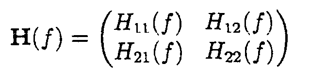
- a MIMO channel is characterized by m inputs, p outputs and m * p linear transfer functions H ij (f), which describe the transfer behavior of the channel from the i-th input to the j-th output.
- the present invention is therefore based on the object to further develop a system of the type mentioned at the beginning, that there is a transmission of at least one digital signal same quality, but with less effort than the well-known DFE concept.
- the at least one to be transmitted digital signal is multi-carrier modulated.
- multi-carrier modulation discrete multitone modulation is particularly useful Consideration (DMT, Discrete Multitone Modulation).
- the invention is based on the idea of using multicarrier modulation on MIMO channels.
- each transfer function H ij (f) in the area of the subband of the kth carrier is constant in sufficient approximation
- the power density spectrum of the effective interference in the kth subband is also constant in sufficient approximation and thus the Disturbance in the kth sub-band almost statistically uncorrelated.
- This enables the equalization of each transfer function H ij (f) - in the sense of a frequency domain equalization - to be multiplied by a generally complex scalar 1 / H ij (f k ), where f k is a frequency value of the kth subband.
- a temporal decorrelation of the disturbance is important with regard to the above statements are not required.
- For the spatial Decorrelation of the disturbance can be the disturbance contribution at the entrance of the i-th decision maker, hereinafter also called discriminator, by linear combination of the disturbance contributions at the inputs of the Decision makers 1 to i - 1 can be estimated and compensated.
- a transmitter for transmitting digital signals with the features of claim 2 is proposed, in which the MIMO concept is combined with the multi-carrier modulation.
- m modulation devices, m ⁇ 2 are used, with each modulation device being able to modulate a number of n i carrier frequencies, n i ⁇ 2, depending on one of m digital signals, and m transformation devices, with each transformation device being one of the n i carriers modulated signals from the frequency range can be transformed into the time range and also a transmission device with which the m time range signals can be fed into the n inputs of a MIMO channel, m ⁇ 2.
- the inverse fast is particularly suitable Fourier transform (IFFT, Inverse Fast Fourier Transform) or the DWMT process (Discrete Wavelet Multitone).
- IFFT Inverse Fast Fourier Transform
- DWMT Discrete Wavelet Multitone
- the m Transformers synchronized by a common clock.
- a receiver for receiving digital signals with the features of claim 4 is proposed, which is designed for the combination of the MIMO concept with a multi-carrier modulation of the digital data. Accordingly, a number of n i carrier frequencies, n i ⁇ 2, are modulated as a function of each digital signal and the received signals are represented in the time domain.
- the receiver has a receiving device which is connected to the p outputs of a MIMO channel with m inputs, the MIMO channel being writable by a transfer function from each of the m inputs to each of the p outputs.
- the receiver has p inverse transformation devices, with each inverse transformation device one of the signals modulated on n i carriers being transformable from the time domain to the frequency domain, a frequency domain equalization device with p inputs and m outputs, which at least partially compensates for the distortion by the transfer function of each of the m Inputs to the p outputs of the MIMO channel, as well as m parallel-serial converters, with which each of the output signals of the frequency domain equalization device can be converted into a serial signal.
- a MIMO receiver offers the advantage of a higher one Transinformation, whereby under Transinformation the over a channel transferable bit rate is to be understood. This has The following causes: On the one hand, crosstalk works adjacent veins in the channel not as a stochastic disturbance, but can be compensated deterministically. Goes on the crosstalk is not lost, but is through a frequency domain equalizer in the useful signal path constructively traced. Finally, the spatial allows Decorrelation of the disorder a significant reduction in am Input of a discriminator effective interference power.
- a so-called SISO line are multi-carrier processes because of the transformation from the frequency range to the time range on the transmitter side or the transformation from the time domain to the Frequency range on the receiver side more complex than time domain equalizer, such as the aforementioned DFE.
- time domain equalizer such as the aforementioned DFE.
- a MIMO frequency domain equalizer and spatial disturbance decorrelation can be thus by simple multiplications.
- Compared the combination of MIMO channel and DFE concept can be seen in the combination of MIMO channel and multi-carrier modulation achieve significantly higher transinformation at reasonable increasing effort.
- the bandwidth of each modulated is particularly advantageous Carrier frequency dimensioned such that the transfer function for each carrier frequency approximately as a complex constant is writable.
- a receiver according to the invention expediently has m decision devices with which the output signals of the Frequency domain equalization device predetermined amplitude values are assignable.
- the receiver according to the invention to a fault decorrelation device with m inputs expand, the interference component in the i-th signal estimated and weighted on the signal i + 1 to n is added.
- M estimation devices can be used to estimate the interference components be provided with which the interference component in the i-th signal thereby It is estimated that the output signal from the input signal the associated decision device for obtaining the estimated value is subtracted.
- the invention further relates to one with the above System according to the invention correlated method for transmission at least one digital signal.
- FIG. 1 shows a transmitter according to the invention.
- the transfer functions from input i to output k are designated H ik (f). They can be in a transmission matrix sum up.
- the DMT method is used as the multi-carrier modulation method.
- the transmitter consists of two identical DMT transmitters 10, 12 with n i carrier frequencies ("tones").
- the message generated by a message source 14 is first converted into binary form in a binary encoder 16.
- the resulting individual bits are then distributed in a demultiplexer 18 to the two DMT transmitters 10, 12.
- the data are first brought into parallel form in a serial-parallel converter 20a, 20b and then distributed to the individual carrier frequencies in a TO (Tone Ordering) block 22a, 22b.
- the signal points of the two-dimensional signal constellation are described by complex numbers.
- the selected signal point S i, k and its conjugate complex s * / i, k serve as inputs to an N point inverse Fast Fourier transformation, see IFFT block 26a, 26b.
- the N-dimensional output vector of the inverse Fast Fourier transform of the i-th DMT transmitter is then converted in a serial / serial manner in a P / S block 28a, 28b and transmitted via the i-th paired wire DA1, DA2.
- the N-dimensional output vector of the IFFT can be provided with a so-called cyclic prefix in a CP block 30a, 30b, which simply precedes the last n values of the vector.
- the transmission signal thus acts periodically.
- FIG. 2 shows the front end of a receiver according to the invention.
- Each of the m double wires of the cable are of the same type Receiving devices connected, the construction of which initially known DMT receiver corresponds.
- the i-th reception signal is converted in a block 32a, 32b in a serial-parallel manner any existing cyclic prefix is discarded.
- the N remaining Samples serve as an input to an N point Fast Fourier transform in an FFT block 34a, 34b.
- the Half of the N output values of the Fast Fourier transform corresponds to the broadcast except for the distortion of the channel Amplitude coefficient, the other half is conjugated complex to the first half and can be discarded.
- On the Fast Fourier Transform joins the frequency domain equalization on.
- FIG. 3 shows the circuit implementation of the multiplication with the inverse transmission matrix in a frequency domain equalizer 40.
- the complex weights b ik are the elements of the inverse of the transmission matrix at the point of the kth tone:
- the effective interference power at the input of a discriminator 36a, 36b is reduced by spatial interference decorrelation.
- the estimated value n and i, k is obtained by forming the difference between the input and output of a discriminator 36 a, 36 b , 36 c, which assigns continuous input values to the possible, discrete amplitude coefficients of the signal constellation of the respective tone.
Abstract
Description
Die vorliegende Erfindung betrifft ein System zur Übertragung mindestens eines digitalen Signals von einer Senderseite auf eine Empfängerseite, wobei die Senderseite über einen MIMO-Kanal mit m Eingängen und p Ausgängen mit der Empfängerseite verbunden ist und die mindestens zwei Ausgänge mit gemeinsamen Empfangsvorrichtungen beschaltet sind, sowie ein korrespondierendes Verfahren. Sie betrifft überdies einen speziell für dieses System ausgebildeten Sender sowie einen speziell ausgebildeten Empfänger.The present invention relates to a transmission system at least one digital signal from a transmitter side a receiver side, the transmitter side via a MIMO channel with m inputs and p outputs with the receiver side is connected and the at least two outputs with common Receiving devices are connected, as well as a corresponding one Method. It also affects one specifically for this System trained transmitter as well as a special trained recipient.
Mit der Abkürzung MIMO (Multiple-Input Multiple-Output) werden
Systeme oder Kanäle mit jeweils mehreren Ein- und Ausgängen
bezeichnet. Die Ein- und Ausgangsgrößen werden häufig zu Vektoren
zusammengefaßt. Aus dem Stand der Technik sind MIMO-Systeme
mit DFE-Empfängern (DFE, Decision Feedback Equalization)
bekannt, Siehe J. Yang und S. Roy: "Joint transmitter-receiver
optimization for multi-input multi-output systems with decision
feedback", erschienen in IEEE Trans. Inform. Theory, 1994,
Volume IT-40, Number 5, Seiten 1334-1347, sowie A. Duel-Hallen:
"Equalizers for multiple input/multiple output channels and PAM
systems with cyclostationary input sequences", erschienen in
IEEE J. Select. Areas Commun., 1992, Volume JSAC-10, Number 3,
Seiten 630-639. Generell wird mit digitalen Modulationsverfahren
die Umsetzung eines zeit- und im allgemeinen wertdiskreten
Signals in ein zeit- und wertkontinuierliches elektrisches Signal
bezeichnet. Man unterscheidet Basisbandverfahren, beispielsweise
Pulsamplitudenmodulation, Einträgerverfahren, beispielsweise
ASK (Amplitude Shift Keying) und Mehrträgerverfahren,
beispielsweise OFDM (Orthogonal Frequency Division Multiplex). With the abbreviation MIMO (Multiple-Input Multiple-Output)
Systems or channels with several inputs and outputs each
designated. The input and output variables often become vectors
summarized. MIMO systems are state of the art
with DFE receivers (DFE, Decision Feedback Equalization)
known, See J. Yang and S. Roy: "Joint transmitter-receiver
optimization for multi-input multi-output systems with decision
feedback ", published in IEEE Trans. Inform. Theory, 1994,
Volume IT-40,
Ein Teil eines derartigen Übertragungsverfahrens dient gewöhnlich der Entzerrung. Hierbei sollen zum einen die Verzerrungen der gesendeten Signals durch den Kanal selbst kompensiert werden, so daß einzelne elektrische Abtastwerte einzelnen digitalen Symbolen der wiedergewonnenen Nachricht zugeordnet werden können. Zum anderen hat ein Entzerrungsverfahren die zeitliche Störungsdekorrelation zu leisten, so daß die Störanteile zeitlich auseinanderliegender elektrischer Abtastwerte statistisch unkorreliert sind.Part of such a transmission method usually serves the equalization. Here, on the one hand, the distortions the transmitted signal are compensated by the channel itself, so that individual electrical samples individual digital Symbols of the retrieved message can be assigned can. On the other hand, an equalization procedure has the temporal To perform interference decorrelation, so that the interference components Statistically separated electrical samples are uncorrelated.
Die Entzerrung und Störungsdekorrelation findet bei der erwähnten DFE im Zeitbereich statt. Im Hinblick auf die Kanalkapazität ist die Entzerrung und Störungsdekorrelation durch DFE optimal.The equalization and interference decorrelation takes place in the mentioned DFE in the time domain. In terms of Channel capacity is equalization and interference decorrelation optimal with DFE.
Zurück zu den MIMO-Kanälen: Ein MIMO-Kanal ist gekennzeichnet durch m Eingänge, p Ausgänge und m*p lineare Übertragungsfunktionen Hij(f), die das Übertragungsverhalten des Kanals vom i-ten Eingang zum j-ten Ausgang beschreiben. Bei derartigen MIMO-Kanälen sind alle möglichen Übertragungswege von allen Eingängen zu allen Ausgängen gemeinsam zu entzerren. Zudem ist für statistische Unkorreliertheit der Störanteile sowohl im zeitlichen Sinne als auch im räumlichen Sinne, also zwischen den gleichzeitigen Störabtastwerten zweier Ausgänge des MIMO-Kanals, zu sorgen.Back to the MIMO channels: A MIMO channel is characterized by m inputs, p outputs and m * p linear transfer functions H ij (f), which describe the transfer behavior of the channel from the i-th input to the j-th output. With such MIMO channels, all possible transmission paths from all inputs to all outputs must be equalized together. In addition, it must be ensured that the interference components are statistically uncorrelated, both in the temporal and in the spatial sense, i.e. between the simultaneous interference samples of two outputs of the MIMO channel.
Nachteilig an der Erweiterung des DFE-Konzepts auf MIMO-Kanäle, siehe die oben erwähnten beiden Veröffentlichungen, ist der mit der Dimension des MIMO-Systems, d. h. der Anzahl der Ein- und Ausgänge, überproportional stark steigende Aufwand.A disadvantage of expanding the DFE concept to MIMO channels, see the two publications mentioned above, is the one with the dimension of the MIMO system, d. H. the number of inputs and Exits, disproportionately increasing effort.
Der vorliegenden Erfindung liegt deshalb die Aufgabe zugrunde, ein System der eingangs genannten Art derart weiterzubilden, daß es eine Übertragung mindestens eines digitalen Signals bei gleicher Qualität, jedoch mit niedrigerem Aufwand ermöglicht als das bekannte DFE-Konzept.The present invention is therefore based on the object to further develop a system of the type mentioned at the beginning, that there is a transmission of at least one digital signal same quality, but with less effort than the well-known DFE concept.
Diese Aufgabe wird erfindungsgemäß dadurch gelöst, daß bei dem gattungsgemäßen System das mindestens eine zu übertragende digitale Signal Mehrträger-moduliert ist. Als Mehrträger-Modulation kommt insbesondere die diskrete Multitone-Modulation in Betracht (DMT, Discrete Multitone Modulation).This object is achieved in that generic system the at least one to be transmitted digital signal is multi-carrier modulated. As multi-carrier modulation discrete multitone modulation is particularly useful Consideration (DMT, Discrete Multitone Modulation).
Die Erfindung basiert auf der Idee die Mehrträger-Modulation
auf MIMO-Kanäle anzuwenden. Bei genügend großer Anzahl von
Trägern ist zum einen jede Übertragungsfunktion Hij(f) im
Bereich des Teilbandes des k-ten Trägers in ausreichender
Näherung konstant, zum anderen das Leistungsdichtespektrum der
wirksamen Störung im k-ten Teilband ebenfalls in ausreichender
Nährung konstant und damit die Störung im k-ten Teilband nahezu
statistisch unkorreliert. Dies ermöglicht die Beschränkung der
Entzerrung einer jeden Übertragungsfunktion Hij(f) - im Sinne
einer Frequenzbereichsentzerrung - auf die Multiplikation mit
einem im allgemeinen komplexwertigen Skalar 1/Hij(fk), wobei fk
ein Frequenzwert des k-ten Teilbandes ist.The invention is based on the idea of using multicarrier modulation on MIMO channels. With a sufficiently large number of carriers, on the one hand each transfer function H ij (f) in the area of the subband of the kth carrier is constant in sufficient approximation, on the other hand the power density spectrum of the effective interference in the kth subband is also constant in sufficient approximation and thus the Disturbance in the kth sub-band almost statistically uncorrelated. This enables the equalization of each transfer function H ij (f) - in the sense of a frequency domain equalization - to be multiplied by a generally
Eine zeitliche Dekorrelation der Störung ist im Hinblick auf
die obigen Ausführungen nicht erforderlich. Für die räumliche
Dekorrelation der Störung kann der Störbeitrag am Eingang des
i-ten Entscheiders, im folgenden auch Diskriminator genannt,
durch lineare Kombination der Störbeiträge an den Eingängen der
Entscheider 1 bis i - 1 geschätzt und kompensiert werden.A temporal decorrelation of the disturbance is important with regard to
the above statements are not required. For the spatial
Decorrelation of the disturbance can be the disturbance contribution at the entrance of the
i-th decision maker, hereinafter also called discriminator,
by linear combination of the disturbance contributions at the inputs of the
Gemäß einem weiteren Aspekt der Erfindung wird ein Sender zum
Senden von digitalen Signalen mit den Merkmalen von Anspruch 2
vorgeschlagen, in dem das MIMO-Konzept mit der Mehrträgermodulation
kombiniert ist. Hierbei werden m Moduliervorrichtungen,
m ≥ 2 verwendet, wobei mit jeder Moduliervorrichtung eine
Anzahl von ni Trägerfrequenzen, ni ≥ 2, in Abhängigkeit eines
von m digitalen Signalen modulierbar ist, ferner m Transformationsvorrichtungen,
wobei mit jeder Transformationsvorrichtung
eines der auf ni Träger modulierten Signale vom Frequenzbereich
in den Zeitbereich transformierbar ist und weiterhin eine
Sendevorrichtung, mit der die m Zeitbereichsignale in die n
Eingänge eines MIMO-Kanals, m ≥ 2, einspeisbar sind. According to a further aspect of the invention, a transmitter for transmitting digital signals with the features of
Zur Transformation vom Frequenzbereich in den Zeitbereich eignet sich beispielsweise besonders die inverse schnelle Fourier-Transformation (IFFT, Inverse Fast-Fourier-Transformation) oder auch das DWMT-Verfahren (Discrete Wavelet Multitone).For the transformation from the frequency domain to the time domain For example, the inverse fast is particularly suitable Fourier transform (IFFT, Inverse Fast Fourier Transform) or the DWMT process (Discrete Wavelet Multitone).
Bei einer besonders vorteilhaften Ausführungsform sind die m Transformationsvorrichtungen durch einen gemeinsamen Takt synchronisiert.In a particularly advantageous embodiment, the m Transformers synchronized by a common clock.
Gemäß einem weiteren Aspekt der Erfindung wird ein Empfänger
zum Empfangen von digitalen Signalen mit den Merkmalen von
Anspruch 4 vorgeschlagen, der auf die Kombination des MIMO-Konzepts
mit einer Mehrträgermodulation der digitalen Daten
ausgelegt ist. Dementsprechend sind eine Anzahl von ni
Trägerfrequenzen, ni ≥ 2, in Abhängigkeit jedes digitalen Signals
moduliert und die empfangenen Signale sind im Zeitbereich
repräsentiert. Der Empfänger verfügt über eine Empfangsvorrichtung
die an den p Ausgängen eines MIMO-Kanals mit m
Eingängen angeschlossen ist, wobei der MIMO-Kanal durch je eine
Übertragungsfunktion von jedem der m Eingänge auf jeden der p
Ausgänge beschreibbar ist. Weiterhin weist der Empfänger p
Rücktransformationsvorrichtungen auf, wobei mit jeder
Rücktransformationsvorrichtung eines der auf ni Träger
modulierten Signale vom Zeitbereich in den Frequenzbereich
transformierbar ist, eine Frequenzbereichentzerrungsvorrichtung
mit p Eingängen und m Ausgängen, die eine zumindest teilweise
Kompensation der Verzerrung durch die Übertragungsfunktion
jedes der m Eingänge auf die p Ausgänge des MIMO-Kanals
ermöglicht, sowie m Parallel-Seriell-Wandler, mit denen jedes
der Ausgangssignale der Frequenzbereichsentzerrungsvorrichtung
in ein serielles Signal umwandelbar ist.According to a further aspect of the invention, a receiver for receiving digital signals with the features of
Grundsätzlich bietet ein MIMO-Empfänger den Vorteil einer höheren Transinformation, wobei unter Transinformation die über einen Kanal übertragbare Bitrate zu verstehen ist. Dies hat folgende Ursachen: Zum einen wirkt das Übersprechen benachbarter Adern im Kanal nicht als stochastische Störung, sondern kann deterministisch kompensiert werden. Weiterhin geht die übersprechende Leistung nicht verloren, sondern wird durch einen Frequenzbereichsentzerrer in den Nutzsignalpfad konstruktiv zurückgeführt. Schließlich ermöglicht die räumliche Dekorrelation der Störung eine signifikante Verminderung der am Eingang eines Diskriminators wirksamen Störleistung.Basically, a MIMO receiver offers the advantage of a higher one Transinformation, whereby under Transinformation the over a channel transferable bit rate is to be understood. this has The following causes: On the one hand, crosstalk works adjacent veins in the channel not as a stochastic disturbance, but can be compensated deterministically. Goes on the crosstalk is not lost, but is through a frequency domain equalizer in the useful signal path constructively traced. Finally, the spatial allows Decorrelation of the disorder a significant reduction in am Input of a discriminator effective interference power.
Durch die Kombination eines Mehrträgerverfahrens mit einem MIMO-Kanal ergeben sich folgende Vorteile: Für eine einzelne Übertragungsleitung, eine sogenannte SISO-Leitung (single-in single-out) sind Vielträgerverfahren wegen der Transformation vom Frequenzbereich in den Zeitbereich auf der Senderseite beziehungsweise der Transformation vom Zeitbereich in den Frequenzbereich auf der Empfängerseite aufwendiger als Zeitbereichsentzerrer, wie zum Beispiel das erwähnte DFE. Jedoch ist bei einem m-dimensionalen MIMO-Mehrträgersystem der Aufwand für die erwähnten Transformationen identisch wie bei m-eindimensionalen Mehrträgersystemen. Ein MIMO-Frequenzbereichsentzerrer und eine räumliche Störungsdekorrelation lassen sich somit durch einfache Multiplikationen realisieren. Im Vergleich zur Kombination aus MIMO-Kanal und DFE-Konzept läßt sich bei der Kombination aus MIMO-Kanal und Mehrträgermodulation eine erheblich höhere Transinformation erreichen bei vertretbar steigendem Aufwand.By combining a multi-carrier process with one MIMO channel has the following advantages: For a single one Transmission line, a so-called SISO line (single-in single-out) are multi-carrier processes because of the transformation from the frequency range to the time range on the transmitter side or the transformation from the time domain to the Frequency range on the receiver side more complex than time domain equalizer, such as the aforementioned DFE. However is the effort with an m-dimensional MIMO multi-carrier system for the transformations mentioned identical to m-one-dimensional Multi-carrier systems. A MIMO frequency domain equalizer and spatial disturbance decorrelation can be thus by simple multiplications. Compared the combination of MIMO channel and DFE concept can be seen in the combination of MIMO channel and multi-carrier modulation achieve significantly higher transinformation at reasonable increasing effort.
Besonders vorteilhaft ist dazu die Bandbreite jeder modulierten Trägerfrequenz derart bemessen, daß die Übertragungsfunktion für jede Trägerfrequenz näherungsweise als komplexwertige Konstante beschreibbar ist.The bandwidth of each modulated is particularly advantageous Carrier frequency dimensioned such that the transfer function for each carrier frequency approximately as a complex constant is writable.
Ein erfindungsgemäßer Empfänger weist zweckmäßigerweise m Entscheidungsvorrichtungen auf, mit denen die Ausgangssignale der Frequenzbereichsentzerrungsvorrichtung vorbestimmten Amplitudenwerten zuordenbar sind.A receiver according to the invention expediently has m decision devices with which the output signals of the Frequency domain equalization device predetermined amplitude values are assignable.
Besonders vorteilhaft ist es, den erfindungsgemäßen Empfänger. um eine Störungsdekorrelationsvorrichtung mit m Eingängen zu erweitern, wobei der Störanteil im i-ten Signal geschätzt und gewichtet auf die Signal i + 1 bis n addiert wird. It is particularly advantageous for the receiver according to the invention. to a fault decorrelation device with m inputs expand, the interference component in the i-th signal estimated and weighted on the signal i + 1 to n is added.
Zur Schätzung der Störanteile können m Schätzungvorrichtungen vorgesehen sein, mit denen der Störanteil im i-ten Signal dadurch schätzbar ist, daß das Ausgangssignal vom Eingangssignal der zugehörigen Entscheidungsvorrichtung zum Erhalt des Schätzwerts subtrahiert wird.M estimation devices can be used to estimate the interference components be provided with which the interference component in the i-th signal thereby It is estimated that the output signal from the input signal the associated decision device for obtaining the estimated value is subtracted.
Die Erfindung betrifft weiterhin ein mit dem obenbezeichneten erfindungsgemäßen System korreliertes Verfahren zur Übertragung mindestens eines digitalen Signals.The invention further relates to one with the above System according to the invention correlated method for transmission at least one digital signal.
Weitere vorteilhafte Ausführungsformen können den Unteransprüchen entnommen werden. Im Nachfolgenden wird ein Ausführungsbeispiel unter Hinweis auf die beigefügten Zeichnungen näher beschrieben. Es stellen dar:
- Fig. 1
- in schematischer Darstellung eine Ausführungsform eines erfindungsgemäßen Senders;
- Fig. 2
- in schematischer Darstellung das Frontend eines erfindungsgemäßen Empfängers;
- Fig. 3
- in schematischer Darstellung einen Teilbereich einer besonders bevorzugten Ausführungsform eines erfindungsgemäßen Empfängers; und
- Fig. 4
- in schematischer Darstellung einen Teilbereich einer weiteren bevorzugten Ausführungsform eines erfindungsgemäßen Empfängers.
- Fig. 1
- a schematic representation of an embodiment of a transmitter according to the invention;
- Fig. 2
- the front end of a receiver according to the invention in a schematic representation;
- Fig. 3
- a schematic representation of a portion of a particularly preferred embodiment of a receiver according to the invention; and
- Fig. 4
- a schematic representation of a portion of a further preferred embodiment of a receiver according to the invention.
Figur 1 zeigt einen erfindungsgemäßen Sender. Ein Kabelbündel
mit zwei Doppeladern DA1, DA2 läßt sich als linear verzerrender
MIMO-Kanal mit m = 2 Eingängen und p = 2 Ausgängen beschreiben.
Die Übertragungsfunktionen von Eingang i zu Ausgang k werden
mit Hik(f) bezeichnet. Sie lassen sich in einer Übertragungsmatrix
Als Mehrträgermodulierverfahren wird im vorliegenden Ausführungsbeispiel
das DMT-Verfahren verwendet. Der Sender besteht
aus zwei gleichartigen DMT-Sendern 10, 12 mit ni Trägerfrequenzen
("Tönen"). Die von einer Nachrichtenquelle 14 erzeugte
Nachricht wird zunächst in einem Binärkodierer 16 in binäre
Form gewandelt. Die daraus entstandenen einzelnen Bits werden
dann in einem Demultiplexer 18 auf die zwei DMT-Sender 10, 12
verteilt. In jedem DMT-Sender werden die Daten zunächst in
einem Seriell-Parallel-Wandler 20a, 20b in parallele Form
gebracht und dann in einem TO- (Tone Ordering) Block 22a, 22b
auf die einzelnen Trägerfrequenzen verteilt. In einem Mapping-Block
24a, 24b wird durch die bi,k Bits, die dem k-ten Ton des i-ten
DMT-Senders zugeteilt sind, einer von 2 b / i,k Signalpunkten
einer zweidimensionalen Signalkonstellation ausgewählt (Mapping
= Abbilden). Die Signalpunkte der zweidimensionalen Signalkonstellation
werden dabei durch komplexe Zahlen beschrieben. Der
ausgewählte Signalpunkt Si,k und seine konjugiert komplexe s * / i,k
dienen als Eingänge in eine N Punkte inverse Fast-Fourier-Transformation,
siehe IFFT-Block 26a, 26b. Der N-dimensionale
Ausgangsvektor der inversen Fast-Fourier-Transformation des i-ten
DMT-Senders wird anschließend in einem P/S-Block 28a, 28b
parallel-seriell gewandelt und über die i-te Doppelader DA1,
DA2 übertragen. Der N-dimensionale Ausgangsvektor der IFFT kann
vor der Parallel-Seriell-Wandlung in einem CP-Block 30a, 30b
mit einem sogenannten Cyclic Prefix versehen werden, das
einfach die n letzten Werte des Vektors diesem noch einmal
voranstellt. Damit wirkt das Sendesignal periodisch.In the present exemplary embodiment, the DMT method is used as the multi-carrier modulation method. The transmitter consists of two
Figur 2 zeigt das Frontend eines erfindungsgemäßen Empfängers. An jede der m Doppeladern des Kabels sind gleichartige Empfangsvorrichtungen angeschlossen, deren Aufbau zunächst dem bekannter DMT-Empfänger entspricht. Das i-te Empfangssignal wird in einem Block 32a, 32b seriell-parallel gewandelt, ein gegebenenfalls vorhandenes Cyclic Prefix verworfen. Die N verbleibenenden Abtastwerte dienen als Eingang in eine N Punkte Fast-Fourier-Transformation in einem FFT-Block 34a, 34b. Die Hälfte der N Ausgangswerte der Fast-Fourier-Transformation korrespondiert bis auf die Verzerrungen des Kanals mit den gesendeten Amplitudenkoeffizienten, die andere Hälte ist konjugiert komplex zur ersten Hälfte und kann verworfen werden. An die Fast-Fourier-Transformation schließt sich die Frequenzbereichsentzerrung an.Figure 2 shows the front end of a receiver according to the invention. Each of the m double wires of the cable are of the same type Receiving devices connected, the construction of which initially known DMT receiver corresponds. The i-th reception signal is converted in a block 32a, 32b in a serial-parallel manner any existing cyclic prefix is discarded. The N remaining Samples serve as an input to an N point Fast Fourier transform in an FFT block 34a, 34b. The Half of the N output values of the Fast Fourier transform corresponds to the broadcast except for the distortion of the channel Amplitude coefficient, the other half is conjugated complex to the first half and can be discarded. On the Fast Fourier Transform joins the frequency domain equalization on.
Wenn r1,k der Ausgangswert des k-ten Tons der FFT des ersten
Empfängers, s1,k der entsprechende gesendete Amplitudenkoeffizient
des Senders 10, und s2,k der entsprechende gesendete Wert
des Senders 12 ist, dann gilt in guter Näherung:
fk ist dabei die Frequenz des k-ten Tons. Die Näherung ist umso
besser, je enger der Abstand benachbarter Töne im Vergleich zur
Änderung der Übertragungsfunktionen Hij(f) im Bereich des halben
Abstand ist. Faßt man jeweils die Ausgangssignale der k-ten
Töne aller m FFTs zu einem Zeilenvektor
Die verzerrende Wirkung des MIMO-Kanals läßt sich also durch
Multiplikation mit der inversen Übertragungsmatrix kompensieren:
Figur 3 zeigt die schaltungstechnische Realisierung der Multiplikation
mit der inversen Übertragungsmatrix in einem
Frequenzbereichsentzerrer 40. Die komplexen Gewichte bik sind
die Elemente der Inversen der Übertragungsmatrix an der Stelle
des k-ten Tons:

Im Hinblick auf die Dekorrelation kann davon ausgegangen werden, daß die m Ausgangssignale des MIMO-Kanals additiv durch m untereinander korrelierte, farbige Störsignale gestört werden. Auf die Signale rik wirkt dies als additiv überlagerte - näherungsweise - weiße Störung ni,k, wobei ni,k und nj,1 korreliert sind für i ≠ j und k = 1 und unkorreliert sind für i = j und k ≠ 1 ("räumliche Korrelation").With regard to decorrelation, it can be assumed that the m output signals of the MIMO channel are additively disturbed by m interfering, colored interference signals. On the signals r ik, this acts as an additively superimposed - approximately - white disturbance n i, k , where n i, k and n j, 1 are correlated for i ≠ j and k = 1 and uncorrelated for i = j and k ≠ 1 ("spatial correlation").
Die Korrelationseigenschaften des Störvektors
Die wirksame Störleistung am Eingang eines Diskriminators 36a, 36b wird durch räumliche Störungsdekorrelation reduziert. Dazu werden vom Eingang des i-ten Detektors die mit dj,k gewichteten geschätzten Störwerte n andj,k der Empfänger j = 1 bis i - 1 subtrahiert, in Figur 3 nicht dargestellt.The effective interference power at the input of a discriminator 36a, 36b is reduced by spatial interference decorrelation. For this purpose, the estimated interference values n and j, k of the receivers j = 1 to i − 1, weighted with d j, k , are subtracted from the input of the i-th detector, not shown in FIG. 3.
Figur 4 zeigt die Störungsdekorrelation für einen Empfänger mit
m = 3 und entsprechend drei Diskriminatoren 36 a, 36 b, 36 c in
einem Frequenzbereichsentzerrer 42. Der Schätzwert n andi,k wird
durch Differenzbildung von Eingang und Ausgang eines Diskriminators
36 a, 36 b, 36 c gewonnen, der wertkontinuierliche
Eingangswerte den möglichen, diskreten Amplitudenkoeffizienten
der Signalkonstellation des jeweiligen Tons zuordnet.FIG. 4 shows the interference decorrelation for a receiver with m = 3 and correspondingly three discriminators 36 a, 36 b, 36 c in a
Das obige Ausführungsbeispiel wurde am Beispiel der DMT als Vielträgerverfahren dargestellt. Andere für die Erfindung in Betracht kommende Vielträgerverfahren sind beispielsweise DWMT (Discrete Wavelet Multitone), OFDM (Orthogonal Frequency Division Multiplex).The example above was used as an example of the DMT Multi-carrier process shown. Others for the invention in Possible multi-carrier processes are, for example, DWMT (Discrete Wavelet Multitone), OFDM (Orthogonal Frequency Division Multiplex).
Claims (10)
dadurch gekennzeichnet, daß das mindestens eine zu übertragende digitale Signal Mehrträger-moduliert ist.System for transmitting at least one digital signal from a transmitter side to a receiver side, the transmitter side being connected to the receiver side via a MIMO channel with m inputs and p outputs, and the at least two outputs being connected to common receiving devices,
characterized in that the at least one digital signal to be transmitted is multi-carrier modulated.
dadurch gekennzeichnet, daß die m Transformationsvorrichtungen (26 a, 26 b) durch einen gemeinsamen Takt (38) synchronisiert sind. Transmitter according to claim 2,
characterized in that the m transformation devices (26 a, 26 b) are synchronized by a common clock (38).
dadurch gekennzeichnet, daß die Bandbreite jeder modulierten Trägerfrequenz derart bemessen ist, daß die Übertragungsfunktion für jede Trägerfrequenz näherungsweise als komplexwertige Konstante beschreibbar ist.Receiver according to claim 4,
characterized in that the bandwidth of each modulated carrier frequency is dimensioned such that the transfer function for each carrier frequency can be approximately described as a complex constant.
dadurch gekennzeichnet, daß er weiterhin umfaßt:
m Entscheidungsvorrichtungen (36 a, 36 b, 36 c), mit denen die Ausgangssignale der Frequenzbereichsentzerrungsvorrichtung (40; 42) vorbestimmten Amplitudenwerten zuordenbar sind. Receiver according to one of claims 4 or 5,
characterized in that it further comprises:
m decision devices (36 a, 36 b, 36 c) with which the output signals of the frequency domain equalization device (40; 42) can be assigned to predetermined amplitude values.
dadurch gekennzeichnet, daß er weiterhin umfaßt:
eine Störungsdekorrelationsvorrichtung (42) mit m Eingängen, wobei der Störanteil im i-ten Signal geschätzt und gewichtet auf die Signale i+1 bis n addiert wird.Receiver according to one of claims 4 to 6,
characterized in that it further comprises:
a disturbance decorrelation device (42) with m inputs, the disturbance component in the i-th signal being estimated and added to the signals i + 1 to n.
dadurch gekennzeichnet, daß sie weiterhin umfaßt:
m Schätzvorrichtungen, mit denen der Störanteil im i-ten Signal dadurch schätzbar ist, daß das Ausgangssignal vom Eingangssignal der zugehörigen Entscheidungsvorrichtung (36 a, 36 b, 36 c) zum Erhalt des Schätzwerts subtrahiert wird.Recipient according to claim 7 with reference back to claim 6,
characterized in that it further comprises:
m estimation devices with which the interference component in the i-th signal can be estimated by subtracting the output signal from the input signal of the associated decision device (36 a, 36 b, 36 c) in order to obtain the estimated value.
dadurch gekennzeichnet, daß es auf der Senderseite einen Sender nach einem der Ansprüche 2 bis 3 und/oder auf der Empfängerseite einen Empfänger nach einem der Ansprüche 4 bis 8 umfaßt.System according to claim 1,
characterized in that it comprises on the transmitter side a transmitter according to one of claims 2 to 3 and / or on the receiver side a receiver according to one of claims 4 to 8.
dadurch gekennzeichnet, daß das mindestens eine zu übertragende digitale Signal senderseitig einer Mehrträger-Modulation unterzogen wird.Method for transmitting at least one digital signal from a transmitter side to a receiver side, the transmitter side being connected to the receiver side via a MIMO channel with m inputs and p outputs, and the at least two outputs being connected to common receiving devices,
characterized in that the at least one digital signal to be transmitted is subjected to multi-carrier modulation on the transmitter side.
Priority Applications (1)
| Application Number | Priority Date | Filing Date | Title |
|---|---|---|---|
| EP00107868A EP1146708A1 (en) | 2000-04-12 | 2000-04-12 | Multicarrier transmission system using Multiple-Input Multiple-Output channels |
Applications Claiming Priority (1)
| Application Number | Priority Date | Filing Date | Title |
|---|---|---|---|
| EP00107868A EP1146708A1 (en) | 2000-04-12 | 2000-04-12 | Multicarrier transmission system using Multiple-Input Multiple-Output channels |
Publications (1)
| Publication Number | Publication Date |
|---|---|
| EP1146708A1 true EP1146708A1 (en) | 2001-10-17 |
Family
ID=8168444
Family Applications (1)
| Application Number | Title | Priority Date | Filing Date |
|---|---|---|---|
| EP00107868A Withdrawn EP1146708A1 (en) | 2000-04-12 | 2000-04-12 | Multicarrier transmission system using Multiple-Input Multiple-Output channels |
Country Status (1)
| Country | Link |
|---|---|
| EP (1) | EP1146708A1 (en) |
Citations (2)
| Publication number | Priority date | Publication date | Assignee | Title |
|---|---|---|---|---|
| WO1998009381A1 (en) * | 1996-08-29 | 1998-03-05 | The Board Of Trustees Of The Leland Stanford Junior University | High capacity wireless communication using spatial subchannels |
| US5867478A (en) * | 1997-06-20 | 1999-02-02 | Motorola, Inc. | Synchronous coherent orthogonal frequency division multiplexing system, method, software and device |
-
2000
- 2000-04-12 EP EP00107868A patent/EP1146708A1/en not_active Withdrawn
Patent Citations (2)
| Publication number | Priority date | Publication date | Assignee | Title |
|---|---|---|---|---|
| WO1998009381A1 (en) * | 1996-08-29 | 1998-03-05 | The Board Of Trustees Of The Leland Stanford Junior University | High capacity wireless communication using spatial subchannels |
| US5867478A (en) * | 1997-06-20 | 1999-02-02 | Motorola, Inc. | Synchronous coherent orthogonal frequency division multiplexing system, method, software and device |
Non-Patent Citations (1)
| Title |
|---|
| KADEL G: "DIVERSITY AND EQUALIZATION IN FREQUENCY DOMAIN - A ROBUST AND FLEXIBLE RECEIVER TECHNOLOGY FOR BROADBAND MOBILE COMMUNICATION SYSTEMS", IEEE VEHICULAR TECHNOLOGY CONFERENCE,US,NEW YORK, IEEE, vol. CONF. 47, 4 May 1997 (1997-05-04), pages 894 - 898, XP000736737, ISBN: 0-7803-3660-7 * |
Similar Documents
| Publication | Publication Date | Title |
|---|---|---|
| DE69925178T2 (en) | Reduction of interference in multi-tone transmission systems with duplex operation | |
| DE69736614T2 (en) | METHOD AND DEVICE FOR SUPPRESSING THE SUB-SPEED | |
| DE69633670T2 (en) | PULSE SHAPING FOR MULTI-LEAD MODULATION | |
| DE60303598T2 (en) | METHOD AND SYSTEM FOR MULTICANAL TRANSMITTER AND RECEIVER WITH AMPLITUDE AND PHASE CALIBRATION | |
| DE60303109T2 (en) | Method and apparatus for selecting subcarriers according to quality of service requirements in a multi-carrier communication system | |
| DE69906548T2 (en) | DSL transmission system with remote crosstalk compensation | |
| DE60005374T2 (en) | OFDM system with transmitter antenna diversity and pre-equalization | |
| DE102009033595B4 (en) | Method, device and communication unit | |
| EP1727324A1 (en) | Radio transmission with guard interval of variable length | |
| WO2003026193A1 (en) | Method and communication system device for the generation or processing of ofdm symbols in a transmission system with spread user data | |
| DE602004006583T2 (en) | Apparatus and method for suppressing interference signals in a multiple antenna system | |
| DE69828109T2 (en) | Generation of the addresses of a coefficient memory in an equalizer for multicarrier signals | |
| DE69922176T2 (en) | IMPROVEMENTS AT VDSL | |
| EP2522082B1 (en) | Device and method for compensating for and identifying far-end crosstalk | |
| EP1620959B1 (en) | Method and transmitter for transmitting data in a multi-carrier system via a number of transmitting antennas | |
| DE19838295B4 (en) | Adaptive subcarrier selection to reduce the peak values of a multicarrier signal | |
| DE60318754T2 (en) | MULTI-CARRIER SYSTEM WITH SENDING DIVERSITY | |
| DE60128312T2 (en) | Equalization in the frequency domain | |
| DE19543622C2 (en) | Method and device for the bidirectional transmission of high-rate digital signals | |
| EP1217760A1 (en) | Apparatus and method for data communication over power line network | |
| EP1146708A1 (en) | Multicarrier transmission system using Multiple-Input Multiple-Output channels | |
| DE60107407T2 (en) | Multi-user detection in a MC-CDMA telecommunications system | |
| DE102006041454B4 (en) | Method for identifying crosstalk in telecommunications | |
| DE102004061854B3 (en) | Method and device for generating a periodic training signal | |
| DE19827514A1 (en) | Multiple carrier signal transmission method for parallel transmission over several sub channels |
Legal Events
| Date | Code | Title | Description |
|---|---|---|---|
| PUAI | Public reference made under article 153(3) epc to a published international application that has entered the european phase |
Free format text: ORIGINAL CODE: 0009012 |
|
| AK | Designated contracting states |
Kind code of ref document: A1 Designated state(s): AT BE CH CY DE DK ES FI FR GB GR IE IT LI LU MC NL PT SE |
|
| AX | Request for extension of the european patent |
Free format text: AL;LT;LV;MK;RO;SI |
|
| AKX | Designation fees paid | ||
| REG | Reference to a national code |
Ref country code: DE Ref legal event code: 8566 |
|
| STAA | Information on the status of an ep patent application or granted ep patent |
Free format text: STATUS: THE APPLICATION IS DEEMED TO BE WITHDRAWN |
|
| 18D | Application deemed to be withdrawn |
Effective date: 20020518 |