BACKGROUND OF THE INVENTION
Field of the Invention
-
The present invention relates generally to a mechanical locking system
and particularly to a brake-transmission interlock system (BTSI) for a motor vehicle.
Description of the Related Art
-
Locking arrangements for selector levers of a motor vehicle transmission
have been required in U.S. vehicles for a substantial number of years. The
purpose of these devices is to prevent accidental engagement of the vehicle.
Relatively more recently, regulations have required systems where the operator must
engage the braking mechanism before moving the selector lever to the desired gear.
-
Traditionally, vehicles having these types of brake-transmission
interlock systems must be moved out of a neutral position (parking or neutral) into a
driving position in order to be able to drive the vehicle. The vehicle may start to
drive, although this is not intended, when, while the engine is running, the selector
lever is inadvertently moved from the neutral position into a driving position. An
unattended abrupt acceleration may also occur during the warmup phase of the
engine, when the idling speed is increased and the selective lever is brought into a
driving position.
-
In order to avoid such circumstances, it is known to provide a locking
arrangement for the selector lever, particularly for automatic vehicle transmissions,
in which a locking member locks the selector lever when the brake is not operated.
The locking member engages in corresponding indentations of an adjustable pawl so
that the selector level is locked in the neutral position (parking or neutral).
-
United States Patent 5,379,872 discloses a locking assembly for an
automatic transmission selector lever which includes a locking member arranged on
the selector lever, and an adjustable pawl. The adjustable pawl has indentations into
which the locking member engages when the brake is not operated so that the selector
lever is locked in the neutral position. The pawl has steeply extending flanks which
bound the indentations where the locking member rests when the selector lever is
locked and an actuating force is applied to the selector lever. The actuating force is
introduced into the flanks of the pawl via contact surfaces of the selector lever at a
contact point of the flanks. The flanks provide a substantially horizontal force
component and a substantially vertical force component of the actuating force. As a
result, the locking arrangement permits a secure unlocking when there are high
operating forces on the locked selector lever. Contact in this manner, the actuating
force applied to the selector lever is introduced in the pawl. On the steep flanks, the
introduced force is transferred into an almost horizontal component pointing in the
direction of the pivot of the pawl and into a downward-directed component which acts
as an almost vertical supporting force. In this case, the steep flanks have the effect
that the supporting force is a low range which is clearly exceeded by the horizontal
component. As a result, the supporting force can act upon the components holding
the pawl in the locked position only with a low power. As a result, the components
can be removed from the pawl by low forces, whereby the pawl, while unlocking the
selector lever, disengages from the locking member.
-
United States Patent 4,817,405 discloses a lock for an automatic
transmission shifter lever which prevents the transmission of the vehicle from being
inadvertently shifted out of the parked position while the vehicle is running. In that
particular invention, a sleeve or collar is received about a steering column in the
vehicle. Mounted on the sleeve is a gear shift lever which can be selectively
manipulated to select the desired gear. As the gear shift lever is manipulated, the
sleeve or collar rotates about a central shaft of the steering column. A lock, including
a rotatable lock cylinder, is mounted near the gear shift lever in the outer casing of the
steering column. The lock extends inwardly and adjacent the sleeve or collar. A
flange or ear extends radially from the lock cylinder and can be rotated between a free
and locked position only by the aid of a key which will operate the lock. The sleeve
or collar includes a receiving slot which, when the gear shift lever is moved to the
park position, is adjacent the extending flange or ear of the lock. The flange or ear
can thus be rotated into the slot by the key to the lock thereby preventing accidental
manipulation of the gear shift lever out of the park position.
-
United States Patent 4,610,336, an automatic transmission locking
mechanism is disclosed which includes a lever rotatively interlocked with a manual
shift lever, a rod adapted to be advanced or retracted by the lever, a parking gear, a
pawl having a detent to be engaged with the parking gear, a cam moved on the rod for
pushing up the pawl with a detent in shifting the manual shift lever to the parking
position, a bracket on which the cam runs and a spring for releasing the pawl from the
parking gear and to retain the pawl at the released position. The pawl is adapted to
be turned on a pawl shaft, and a plate-shaped clamp is fitted in a grove formed in the
pawl shaft at the free end thereof to restrain the actual movement of the pawl. The
clamp is fixed to a case with a bolt with a spring disposed nearby the free end of the
pawl and the sleeve can easily be fitted on or removed from the pawl shaft by
fastening or removing, respectively the bolt fixing the clamp. Other examples of
transmission locking mechanisms can be found in United States Patent 4,585,103;
4,252,219; 4,033,158; 3,960,235; 3,948,339; and 3,939,939.
-
A significant disadvantage with substantially all of the aforementioned
transmission interlock systems is they often require complicated mechanical linkages
and assemblages or electrical circuits and solenoids to engage or disengage the pawls
locking the transmission shifter in place. The purpose of the invention is to produce
a reliable brake transmission interlock system requiring fewer components and
resulting in a less costly assembly.
SUMMARY OF THE INVENTION
-
According to one form of the invention, a brake transmission interlock
system for a transmission shifter assembly is provided which includes a selector lever
cooperating with at least one linking lever such that the movement of the selector
lever results in a corresponding movement of one of the linking levers to select a
desired gear. An assembly for selectively locating the lever at a desired gear selection
position is provided in association with at least one fluid locking assembly cooperating
with the locating assembly to lock the selector lever in a desired position,
preventing accidental disengagement. The fluid locking assembly includes at least
one linear actuator whose movement is controlled by a magneto rheological fluid.
-
In another form of the invention, a transmission shifter assembly
includes a selector lever having a first end and a second end, the second end
interconnected to at least one linking lever such that the movement of the first end of
the selector lever results in a corresponding movement of the linking lever. A
positioning plate is located adjacent the base of the selector lever and includes at least
one aperture configured to receive a locking assembly associated with the selector
lever to selectively fixing a location of the lever. Connected to the locating assembly
is at least one fluid locking member which selectively permits movement of the
locating assembly with respect to the aperture. In further embodiment of the
invention, an assembly is provided which cooperates with the lever to produce a
magnetic field about the fluid locking member when the selector lever is in a
predetermined position. Additionally, at least one of a braking operation and a key
operation cooperates with the magnetic field assembly to selectively lock and unlock
the fluid locking member.
-
In yet another form of the invention, the transmission shifter assembly
includes a lever having a lower end coupled to at least one linking lever such that the
movement of the lever assembly results in a movement of the linking lever to select
a desired gear. A pawl is attached to the lower end of the lever assembly and is
moveable between a first and second position. Connected to the pawl is an actuator
assembly configured to selectively move the pawl between a first and second position.
Adjacent the lever is a positioning plate having a plurality of detents configured to
receive at least a portion of the moveable pawl to selectively fix a position of the lever
assembly. In still a further form of the invention, at least one of the braking operating
and key operation cooperates with the actuator assembly to selectively lock and
unlock the actuator assembly.
-
In the most basic form of the invention, a magneto rheological fluid
locking member comprises the principal element of the brake transmission interlock
system, providing the interconnecting element between the locking pawl of the shifter
assembly and a release button engaged by the operator. The magneto rheological
fluid locking member cooperates with at least one of a braking operation and key
operation to selectively engage and disengage a magnetic field which alters the
operational characteristics of the assembly.
BRIEF DESCRIPTION OF THE DRAWINGS
-
- Fig. 1 is schematic view of one embodiment of a brake-transmission
interlock system embodying the present invention;
- Fig. 2 is a schematic side view of a portion of the brake-transmission
interlock system taken along a line 2-2 of Fig. 1;
- Fig. 3 is a enlarged schematic view of a handle portion of the brake-transmission
interlock system of Fig. 1;
- Fig. 4 is an enlarged schematic view of a lower portion of the brake-transmission
interlock system shown in Fig. 1;
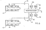
- Fig. 5 is a schematic diagram of a circuit forming a portion of the
brake- transmission interlock system embodying the invention;
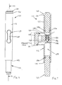
- Fig. 6 is an elevation view of an alternate embodiment of a fluid
locking member; and
- Fig. 7 is a cross-section view of the fluid locking member shown in Fig.
- 6, taken along line VII - VII.
DETAILED DESCRIPTION OF THE VARIOUS EMBODIMENTS
-
-
For purposes of the following description, the terms "upper," "lower,"
"left," "rear," "front," "vertical," "horizontal" and derivatives of such terms shall
relate to the invention as oriented in Fig. 1. However, it is to be understood that the
invention may assume various alternative orientations, except where expressly
specified to the contrary. It is also to be understood that the specific devices and
processes illustrated in the attached drawings, and described in the following
specification are simply exemplary embodiments of the inventive concepts defined
in the appended claims. Specific dimensions and other physical characteristics
relating to the embodiments disclosed herein are not to be considered as limiting,
unless the claims expressly state otherwise.
-
As mentioned above, one of the principal objects of invention is to
replace a substantial number of interconnected components with a single, more
reliable component to complete a brake transmission interlock system. In its most
rudimentary form, the invention includes a non-Newtonian flow fluid locking
mechanism, such as a magneto rheological fluid locking member, in cooperation with
at least one of a braking operation or a key operation, to engage and disengage a
locking pawl to prevent accidental engagement of the vehicle transmission. In more
simpler terms, a fluid locking member is connected to the locking pawl of the shift
lever assembly enabling the operator to shift the selector lever out of the park or
neutral position when the operator has the brakes applied and the ignition is on. It is
further contemplated that the magnetic sources connected to the locking mechanism
is at a position proximate the first fluid locking member when the selector lever is in
the first position to selectively lock and unlock the selector lever. In one embodiment
of the invention, the magnetic source includes two components comprised of a
permanent magnetic, and an electromagnet or coil proximate the permanent magnet
to neutralize the field produced by the permanent magnet and unlock the fluid locking
member. It is also contemplated that a second fluid locking member may be disposed
at an end of the selector lever to enable the operator to selectively actuate the first
fluid locking member. The first fluid locking member may include a tubular housing
having an intermediate restriction and at least one piston disposed within the tubular
housing. A magneto rheological fluid is preferably used to fill the remainder of the
housing. The flow characteristics of the magneto rheological fluid are transformed
by the presence or absence of an electromagnetic field around the restriction, thus
locking and unlocking movement of the piston enclosed therein. To permit
equalization of the fluid after the system has been reset, a check valve is disposed
within the tubular housing which permits one way flow of the magneto rheological
fluid around the restriction.
-
In another form of the invention, the transmission shifter assembly
includes a lever assembly coupled at a lower end to at least one linking lever such that
movement of the lever assembly results in movement of the linking lever to select a
desired gear. A pawl is attached to the lower end of the lever assembly and moveable
between a first and second position. An actuator assembly is connected to the pawl
for moving the pawl between the first and second positions. The pawl engages a
positioning plate having a plurality of detents therein to selectively fix the position of
the lever assembly. To lock and unlock the actuator assembly, a circuit is provided
in cooperation with at least a braking operation and a key operation to create or
neutralize the magnetic field adjacent the actuator assembly. As in the previous
embodiment, the magnetic field may be produced by a permanent magnet and
neutralized by a coil or other electromagnetic source which counteracts the field
produced by the permanent magnet.
-
For a better understanding of the most rudimentary form of the
invention, and various embodiments of the invention, the reader is referred to Figs.
1-4 wherein a hypothetical gear selector lever assembly 10 is shown for a motor
vehicle. The gear selector lever assembly 10 may include a hand grip 12 at an upper
end and a clevis 14 at a lower end. First and second brackets 16 and 18 may be
spaced apart from each other and mounted on the floor 20 of the vehicle to rotatably
support a shaft 22 to which the clevis 14 is secured. The selector lever assembly 10
may be pivotal around the axis of the shaft 22 by manipulating the hand grip 12
between a plurality of angular positions which correspond to a gear selector position
such as "P" for parking, "R" for reverse, "N" for neutral, "D" for automatically
shifting forward driving gear ratios, "2" to lock up second gear and "1" for locking
up first gear as shown by the solid letters in Fig. 2. At least one linking lever 24 may
be connected with the shaft 22 and interconnected to at least one corresponding
linking lever (not shown) at the transmission, so that movement of the selector lever
10 causes a gear changing operation in the transmission.
-
In the schematic shown, the selector lever assembly 10 may include a
lower rod or pawl 26 which may be oriented parallel to shaft 22 and which may be
movable in an axial direction of selector lever assembly 10. The pawl 26 may be
moved downward by pushing button 28 provided on the hand grip 12 and described
in greater detail below. A positioning plate 30, integral with or adjacent to brackets
16 is formed with an arcuately extending aperture 32 into which a portion of the lower
rod 26 is inserted to retain the selector lever 10 in a desired position. Interconnecting
pawl 26 to button 28 is an actuator assembly having an upper rod 36 interconnected
to button 28 by at least one non-Newtonian flow fluid-locking actuating member such
as 40 disclosed in any one of U.S. Patent Nos. 5,277,281; 5,284,330; 5,492,312;
5,816,372; 5,711,746, all assigned to the Lord Corporation, the disclosures of which
are incorporated herein by reference.
-
Fig. 3 schematically illustrates one example of a fluid locking member
40 wherein the button 28 is horizontally actuated. The handle member 12 may
include an upper portion 44 and lower portion 46, the latter of which may be fixed to
the upper end of the lever shaft 47. The two portions 44,46 of the handle can define
an interior cavity 48 configured to receive the fluid locking member 40. The fluid
locking member can include a housing 50 preferably in the shape of a right circular
cylinder closed at one end 52 and having an opening at an opposite end 54 of
sufficient diameter to permit the passage of a shaft 56 there through. The central or
intermediate portion 58 of the housing may be of a reduced diameter intermediate
portion to create a constriction generally uniformly about the perimeter and around
shaft 56. The specific dimension of the reduced intermediate portion (RIP) 58 may
vary depending upon the diameter of the shaft 56. In the instant case, RIP 58
essentially divides the housing 50 into two chambers, each containing a respective
piston 60 and 62. Each of the pistons 60,62 may have a diameter substantially equal
to the interior diameter of the respective chambers. O-rings or similar seals may
extend around the circumference of each piston to form a tight seal with the interior
wall of the chamber. A specific volume is defined between the inwardly facing
surfaces of the pistons and the interior wall of the two chambers. Disposed within this
volume is the non-Newtonian flow fluid similar to that disclosed in the patents owned
by the Lord Corporation. The portions of the respective chambers outboard of the
pistons are preferably vented to ambient through holes extending through the end
walls of the housing to prevent hydraulic lock.
-
Disposed around the housing 50 within the RIP 58 could be a device
for generating a magnetic field within the interior of the housing 50, and particularly
across the inside diameter of the RIP 58. In a preferred embodiment, the device
includes a wire coil operably connected to a power supply. Referring again to Fig.
3, the right hand end of shaft 56 is connected to button 28. Disposed between the end
54 of the housing 50 and button 28 is a spring 64. Additionally, a second spring 66
may be disposed between the end 52 of the housing 50 and the inside wall of the
chamber 48. Although the general shape of the housing 50 is described as a right
circular cylinder, a portion indicated by reference numeral 68 includes a cam surface
which is configured to engage the upper end of the upper rod 36.
-
In addition to, or in an alternate embodiment, the fluid locking member
42 (FIG. 4) may be located lower in the lever assembly 10. It is certainly contemplated
that one or both of the fluid locking members 40 or 42 may be incorporated in
a single structure. In the embodiments shown, the lower end of upper rod 36 extends
through the upper end of the fluid locking member housing 72. The lower end 74 of
the housing 72 is connected to intermediate rod 38 which in turn is coupled to pawl
26. Just as in the previous embodiment, housing 72 is preferably in the form of a right
circular cylinder having a diameter sufficient to slide up and down within the interior
of the lever 10. The lower end of upper rod 36 extends through the upper end 70 of
the housing and is coupled to spaced pistons 76 and 78 disposed on opposite sides of
the RIP 80. Other than the orientation, the fluid locking member 42 may be
substantially identical in all respects to fluid locking member 40 described earlier.
Disposed between the lower end 74 of the housing 72 and the upper end of the clevis
14 and substantially inscribing or encircling the intermediate rod 38 is a spring 82
configured to urge the rods 26,36,38 upwardly. Just as in the previous embodiments,
RIP 80 is configured to house a wire coil operably connected by conductors to an
integrated circuit and power supply.
-
Fig. 5 illustrates schematically one circuit which may be operably
connected to the upper fluid locking member 40 and the lower fluid locking member
42. As mentioned previously, each of the locking members may include a coil which
extends around the RIP generally designated as 90 in the upper locking member 40
and 92 in the lower locking member 42. The coils 90, 92 may be coupled by
conductors 94 and 96 to an integrated circuit or computer generally identified as 98.
The IC or computer may also be operably coupled to a vehicle battery 100 and receive
input signals from sensors or detectors, for example those located at seat belt reel 102,
the brake mechanism 104, the ignition system 106 and a park position switch 107.
Any one or more of these systems 102, 104, 106 or 107 individually or in combination
may control the output by the IC over conductors 94 and 96 to the fluid locking
members 40 and 42.
-
In a preferred method of operation, and as shown in Figs. 1 through 5,
with the input from the ignition system 106 in the "off' position, no power from the
battery 100 is transmitted by the IC to coil 90 or coil 92 to produce a field the fluid.
In the absence of the field, the non-Newtonian fluid in each locking member is
permitted to pass through the RIP, thus no horizontal translation of the housing 50 nor
vertical translation of the housing 72 occurs. In this fashion the spring 66 in the
handle 12 and spring 82 above the clevis 14 prevent vertical actuation of the upper,
intermediate and lower rods 26, 36 and 38, thus preventing movement of the shifter
out of the "park" position. When the ignition switch is moved to the "on" position,
the IC 98 receives a signal from detector 106 which permits battery power to be
transferred over conductor 94 to the coil 90 and locking the respective positions ofthe
piston within the housing. This, in essence, permits the actuation of the button 28 to
be transferred to the housing 50 resulting in horizontal translation and a depression
of the upper rod 36. At this point power is not passed over conductor 96 to coil 92.
Spring 82 places a positive load on intermediate rod 38 maintaining the pawl 26 in
the "P" position. Power is transmitted to coil 92 over conductor 96 upon a signal
from the brake sensor 104 and possibly seat belt sensor 102. Upon receipt of one or
more of these signals, the operator is able to depress the pawl 26 and disengage from
the park position. Thereafter, the park switch 107 is normally closed and keeps
current to coil 92 so the operator may shift. The park switch is open and current to
coil 92 is interrupted when the pawl 26 is moved to the "P" position and the operator
releases the brake.
-
It is contemplated that other forms of the fluid locking members, in
addition to those described above, may be used in association with the instant
invention. For example, an alternate example of the fluid locking mechanism is
illustrated in Figs. 6 and 7. As shown in the Figures, a locking member 110 may
include a hollow or tubular right circular cylinder housing 112 having a general oval-shaped
lateral extension portion 114. Disposed in the upper and lower ends of the
housing 116, 118, respectively are pistons 120, 122, both configured to extend and
retract axially within housing 112. Attached to the top of extension portion 114 is a
cap 124 sealing the generally hollow interior.
-
As best illustrated by Fig. 7, member 110 may include an upper and
lower longitudinal chamber 126, 128 respectively, each in fluid communication with
the other through bypass 130 defined within the oval extension portion 114. Also
interconnecting chambers 126, 128 may be an axial passage 132. In a preferred
embodiment, axial passage 132 includes a check valve 134 formed by a ball 136
sealing against seat 138. Clips or keepers 140 may extend diametrically across axial
passage 132 to retain the ball 136 therein. Thus, in this configuration, if fluid is
unable to flow through bypass 130, fluid should only be able to flow from chamber
128 past check valve 134 and into chamber 126 for reasons which will become
apparent below.
-
As briefly mentioned above, pistons 120, 122 are slidably disposed
within the ends 116, 118 respectively of the housing 112. To ensure a tight seal with
an interior wall of each chamber 126, 128, each piston includes seals generally
designated by reference numerals 142, 144. Together with cap 124, the volume
within bypass 130, chambers 126, 128 and between the inner ends of the pistons is
sealed. In the preferred embodiment, the volume is filled with a non-Newtonian flow
fluid such as one of the types described in the aforementioned patents owned by the
Lord Corporation. For the purposes of this description, this fluid will also be referred
to as a magneto rheological fluid or a locking fluid, all considered to refer substantially
to a fluid having the same flow characteristics when exposed to a magnetic field.
In other respects, the fluid may be akin to a hydraulic fluid in that it is substantially
incompressible, free of air bubbles and the like, and completely filling chamber 126,
128, check valve 134, and bypass 130.
-
With reference to the embodiment of the locking member 110 shown
in Figs. 6 and 7, the reader should note it is preferred, but not necessary, to reduce the
size of the passage extending through bypass 130 from those of chambers 126, 128.
The intent of the size reduction is to maximize the affect of any magnetic field or flux
on the locking fluid passing through the bypass. That is to say, when the locking fluid
is exposed or placed in a magnetic field, the flow characteristics of the locking fluid
change, becoming more viscous, and can substantially become so viscous that flow
becomes extremely difficult through small passages. Thus in a magnetic field free
environment, the locking fluid would preferably flow freely between chambers 126,
128 through bypass 130. In the presence of a magnetic field, and particularly one
passing through bypass 130, the locking fluid may be too viscous to pass, thus
stopping flow and preventing axial movement of pistons 120, 122, causing locking
member 110 to act as a substantially rigid body. In the preferred embodiment, the
strength of the magnetic field may be calculated so as not to extend too far and impact
upon the fluid in chambers 126, 128, but may do so upon the desired application.
However, it is believed that fluid should be free to pass upwardly into chamber 126
through valve 134 to reset the initial positions of the pistons 120, 122 at the
beginning of the desired cycle with or without the presence of a magnetic field across
bypass 130.
-
With respect to the source of the magnetic field, it is contemplated that
a permanent magnet generally positioned relatively proximate cap 124 should be
sufficient to place a continuous magnetic field across the bypass 130. It is further
contemplated that an electromagnetic field, produced by coils located at about the
same location as the magnet, could be constructed to counteract the field produced by
the magnet, rendering the field neutral. By turning the coils on and off using an
electric current, the locking member may be compliant, permitting movement of the
pistons, or rigid, locking the pistons when pressure is applied in a predetermined
direction.
-
Various changes, alternatives, and modifications will become apparent
to those of ordinary skill in the art following a reading of the foregoing description.
For example, although coils have been described to be used in connection with the
fluid locking members, it will be appreciated that electromagnets or permanent
magnets may be utilized to provide some or all of the magnetic field. The intensity
or strength of the magnetic flux through the fluid may be changed by altering the
distance of the magnets or electromagnets from the RIP of the cylinder. Additionally,
although cylinder 42 is described as being located above pawl 26, it is contemplated
that the cylinder may be located below the pawl and in the locked position once the
ignition switch is on to keep a load thereon. The cylinder is de-energized upon
application of the brake as well as possibly an input from the seat belt sensor. It is
further contemplated the instant invention may be adapted for use in steering-column
mounted shifter assemblies as well as other lever mechanisms. Moreover, the instant
invention could assist in controlling the tactile characteristics of the shifter. It is
intended that all such changes, alternatives or modifications are within the scope of
the foregoing description and considered a part of the present invention.
-
The embodiments of the invention in which an exclusive property or
privilege is claimed are defined as follows: