EP1143059A2 - Washing machine with balancer - Google Patents
Washing machine with balancer Download PDFInfo
- Publication number
- EP1143059A2 EP1143059A2 EP00128187A EP00128187A EP1143059A2 EP 1143059 A2 EP1143059 A2 EP 1143059A2 EP 00128187 A EP00128187 A EP 00128187A EP 00128187 A EP00128187 A EP 00128187A EP 1143059 A2 EP1143059 A2 EP 1143059A2
- Authority
- EP
- European Patent Office
- Prior art keywords
- balancer
- washing machine
- water
- inner tub
- water supply
- Prior art date
- Legal status (The legal status is an assumption and is not a legal conclusion. Google has not performed a legal analysis and makes no representation as to the accuracy of the status listed.)
- Granted
Links
Images


Classifications
-
- D—TEXTILES; PAPER
- D06—TREATMENT OF TEXTILES OR THE LIKE; LAUNDERING; FLEXIBLE MATERIALS NOT OTHERWISE PROVIDED FOR
- D06F—LAUNDERING, DRYING, IRONING, PRESSING OR FOLDING TEXTILE ARTICLES
- D06F37/00—Details specific to washing machines covered by groups D06F21/00 - D06F25/00
- D06F37/20—Mountings, e.g. resilient mountings, for the rotary receptacle, motor, tub or casing; Preventing or damping vibrations
- D06F37/22—Mountings, e.g. resilient mountings, for the rotary receptacle, motor, tub or casing; Preventing or damping vibrations in machines with a receptacle rotating or oscillating about a horizontal axis
- D06F37/225—Damping vibrations by displacing, supplying or ejecting a material, e.g. liquid, into or from counterbalancing pockets
-
- D—TEXTILES; PAPER
- D06—TREATMENT OF TEXTILES OR THE LIKE; LAUNDERING; FLEXIBLE MATERIALS NOT OTHERWISE PROVIDED FOR
- D06F—LAUNDERING, DRYING, IRONING, PRESSING OR FOLDING TEXTILE ARTICLES
- D06F33/00—Control of operations performed in washing machines or washer-dryers
- D06F33/30—Control of washing machines characterised by the purpose or target of the control
- D06F33/48—Preventing or reducing imbalance or noise
-
- D—TEXTILES; PAPER
- D06—TREATMENT OF TEXTILES OR THE LIKE; LAUNDERING; FLEXIBLE MATERIALS NOT OTHERWISE PROVIDED FOR
- D06F—LAUNDERING, DRYING, IRONING, PRESSING OR FOLDING TEXTILE ARTICLES
- D06F37/00—Details specific to washing machines covered by groups D06F21/00 - D06F25/00
- D06F37/02—Rotary receptacles, e.g. drums
- D06F37/04—Rotary receptacles, e.g. drums adapted for rotation or oscillation about a horizontal or inclined axis
- D06F37/06—Ribs, lifters, or rubbing means forming part of the receptacle
-
- D—TEXTILES; PAPER
- D06—TREATMENT OF TEXTILES OR THE LIKE; LAUNDERING; FLEXIBLE MATERIALS NOT OTHERWISE PROVIDED FOR
- D06F—LAUNDERING, DRYING, IRONING, PRESSING OR FOLDING TEXTILE ARTICLES
- D06F37/00—Details specific to washing machines covered by groups D06F21/00 - D06F25/00
- D06F37/26—Casings; Tubs
- D06F37/265—Counterweights mounted to the tub; Mountings therefor
Definitions
- the present invention relates generally to a washing machine with a balancer, and more particularly to a washing machine, which is equipped with a balancer on a portion of the inner tub of the washing machine having a horizontally disposed drive shaft, thereby reducing its vibration and noise during a spin-drying process.
- a conventional washing machine includes a cabinet 1.
- a door 3 is openably mounted to the front of the cabinet 1 to allow the laundry to be fed and discharged.
- An outer tub 5 is situated in the cabinet 1 to accommodate water.
- An inner tub 7 provided with a plurality of water passage holes 7a is rotatably positioned in the outer tub 5.
- a lifter 9 is mounted on the bottom of the interior of the inner tub 7 to raise the washing water to a predetermined height and, thereafter, allow it to fall down due to gravitational force.
- a water supply hose 13 passes through the cabinet 1, and a water supply valve 11 is positioned on the water supply hose 13, so as to supply water necessary for washing.
- a detergent container 15 is formed in the upper portion of the cabinet 1 to supply a detergent.
- a water supply bellows 17 is situated between the detergent container 15 and the outer tub 5 to supply to the outer tub 5 water that has been supplied through the water supply hose 13 and has been mixed with the detergent.
- a motor 19 is mounted beneath the outer tub 5.
- a belt 21 and a pulley 23 are situated in the vicinity of the motor 19 to rotate the inner tub 7 normally and reversely.
- a water drain bellows 25 is situated under the outer tub 5 to drain water that is used in the washing machine.
- a drain pump 27 is mounted to the end portion of the drain bellows 25 to pump water that is drained through the water drain bellows 25.
- a drain hose 29 is connected to the drain pump 27 to drain to the outside water pumped by the drain pump 27.
- a water level sensor 31 is positioned in the cabinet 1 so as to sense a water level by means of water pressure to determine if water is supplied to the outer tub 5 or not.
- a gasket 35 is interposed between the door 3 and the outer tub 5 to prevent water contained in the outer tub 5 from leaking.
- Reference numerals 37, 39 and 25a designate a spring for supporting the upper portion of the outer tub 5, a damper for supporting the lower portion of the outer tub 5 and reducing the vibrations of the outer tub 5, and a drain valve, respectively.
- an object of the present invention is to provide a washing machine with a balancer, which is capable of improving the balancing capacity of its balancer to reduce vibration and noise, of preventing the balancer from being damaged due to thermal expansion to increase the durability of the balancer, and of simplifying the manufacture and assembly of the balancer to reduce the manufacturing cost of the washing machine.
- the present invention provides a washing machine, comprising an outer tub for accommodating washing water, an inner tub rotatably mounted in the outer tub for washing and spin-drying the laundry, a balancer mounted to the inner tub to be opened at its one side, the balancer accommodating water to balance the inner tub, water supply means for supplying washing water to the balancer, and a cabinet for constituting the boundary of the washing machine and enclosing the components of the washing machine.
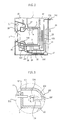
- Fig. 2 is a vertical cross section of a washing machine in accordance with the preferred embodiment of the present invention.
- Fig. 3 is enlarged view of "A" portion of Fig. 2.
- Fig. 4 is an enlarged, exploded perspective view showing the principal components of the washing machine.
- Fig. 5 is a cross section of a balancer in accordance with the preferred embodiment of the present invention.
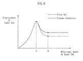
- Fig. 6 is a graph in which the displacements of an inner tub are plotted with regard to the rotational speeds of an inner tub.
- the washing machine of the present invention includes a cabinet 1 that constitutes the boundary of the washing machine.
- a door 3 is openably mounted to the front of the cabinet 1 to allow the laundry to be fed and discharged.
- An outer tub 5 is situated in the cabinet 1 to accommodate washing water.
- An inner tub 7 provided with a plurality of water passage holes 7a is rotatably positioned in the outer tub 5.
- a lifter 9 is mounted on the bottom of the interior of the inner tub 7.
- a water supply means is mounted to the interior of the cabinet 1 to supply washing water to the washing machine.
- a motor 19 is attached beneath the outer tub 5.
- a belt 21 and a pulley 23 are situated in the vicinity of the motor 19 to rotate the inner tub 7 normally and reversely.
- a balancer 100 is mounted to the front end of the inner tub 7 to balance the inner tub 7 during high-speed rotation for a spin-drying process, thereby reducing vibration and noise.
- the balancer 100 may be attached to the front end of the inner tub 7 in a tight-fitting or welding fashion, or may be integrally formed with the inner tub 7.
- the balancer 100 comprises a cylindrical portion 101 extended horizontally, a bell portion 102 expanded downwardly rearward from the rear end of the cylindrical portion 101, a skirt portion 103 extended from the rear end of the bell portion 102 to the rear end of the cylindrical portion 101, and a bent portion 104 extended radially inward from the front end of the skirt portion 103 to be spaced apart from the cylindrical portion 101 and form an opening 105 between the cylindrical portion 101 and itself. Accordingly, a space is formed between the bell portion 102, the skirt portion 103 and the bent portion 104 to accommodate water, and the cylindrical portion 101 is projected forward past the bent portion 104.
- a speed sensor 210 is mounted to a portion of the motor 19 to sense that the rotational speed of the inner tub 7 passes through a critical speed (see “C” in Fig. 6) of the inner tub 7 and reaches a speed (see “B” in Fig. 6) at which the centrifugal force exceeds gravitational force.
- the water supply means is comprised of a water supply source 200, a water supply hose 230 for supplying water from the water supply source 200 to the space 106 of the balancer 100 through the opening 105 of the balancer 100, and a water supply valve 220 mounted on the water supply hose 230 for selectively being opened and closed in response to a signal from the speed sensor 210.
- the critical speed denotes a speed in which the amplitude of vibration is infinitely enlarged due to the coincidence of the natural frequency of the inner tub and the rotational speed of a drive shaft during the rotation of the drive shaft along with the inner tub 7.
- the laundry is raised up to a predetermined height by means of the lifter 9 and lowered down from the height by means of gravitational force, so that the laundry is washed through a mechanical operation.
- the drain valve 25a is opened, washing water is drained through the drain bellows 25, and the washing water having passed through the drain bellows 25 is pumped by the drain pump 27 and drained to the outside through the drain hose 29.
- the motor 19 is rotated in a predetermined direction to spin-dry the laundry and the inner tub 7 is also rotated in the direction, so that the laundry is spin-dried by means of centrifugal force. Water removed from the laundry is drained to the outside through the water passage holes 7a of the inner tub 7, the outer tub 5, the drain bellows 25, the drain pump 27 and the drain hose 29.
- the water supply valve 220 is opened and water is supplied from the water supply source 200 through the water supply hose 230. Water having been supplied through the water supply hose 230 is supplied to the space 106 through the opening 105 of the balancer 100.
- the water having entered the space 106 balances the inner tub 7 tending to lean while being brought into tight contact with and flowing along the inner surface of the skirt portion 103 of the balancer 100 by means of centrifugal force, thereby reducing vibration and noise.
- the balancing capacity of the balancer 100 depends upon the amount of water supplied to the space 106 and the height H of the bent portion 104.
- the balancer 100 is not damaged due to thermal expansion because the balancer 100 can absorb the effect of the thermal expansion due to the presence of the opening 105.
- the speed sensor 210 is described as being mounted to a portion of the motor 19, the position of the speed sensor 210 is not limited to that position, but the speed sensor 210 may be mounted to a portion of the inner tub 7 to sense the rotational speed of the inner tub 7.
- water is described as being supplied through the space 106 of the balancer 100, the washing water can be supplied in other ways. That is, during washing and rinsing processes water may be supplied through a portion of the outer tub 5 as in a conventional art, while during a spin-drying process water may be supplied to the interior of the balancer 100.
- Fig. 6 is a graph in which the maximum displacements of the inner tub 7 with and without the balancer 100 are plotted with regard to the rotational speeds of the inner tub 7.
- an "X" axis represents the rotational speeds of the inner tub 7 during a spin-drying process
- a “Y” axis represents the maximum displacements of the inner tub 7.
- the speed “B” denotes a speed that the inner tub 7 reaches after passing through the critical speed C and at which centrifugal force exceeds gravitational force.
- a dotted line represents the displacements of the inner tub 7 without the balancer 100 with regard to the maximum rotational speed of the inner tub 7 without the balancer 100
- a solid line represents the displacements of the inner tub 7 with the balancer 100 with regard to the maximum rotational speed of the inner tub 7 with the balancer 100.
Abstract
Description
- The present invention relates generally to a washing machine with a balancer, and more particularly to a washing machine, which is equipped with a balancer on a portion of the inner tub of the washing machine having a horizontally disposed drive shaft, thereby reducing its vibration and noise during a spin-drying process.
- As shown in Fig. 1, a conventional washing machine includes a
cabinet 1. Adoor 3 is openably mounted to the front of thecabinet 1 to allow the laundry to be fed and discharged. Anouter tub 5 is situated in thecabinet 1 to accommodate water. - An
inner tub 7 provided with a plurality ofwater passage holes 7a is rotatably positioned in theouter tub 5. Alifter 9 is mounted on the bottom of the interior of theinner tub 7 to raise the washing water to a predetermined height and, thereafter, allow it to fall down due to gravitational force. Awater supply hose 13 passes through thecabinet 1, and awater supply valve 11 is positioned on thewater supply hose 13, so as to supply water necessary for washing. Adetergent container 15 is formed in the upper portion of thecabinet 1 to supply a detergent. Awater supply bellows 17 is situated between thedetergent container 15 and theouter tub 5 to supply to theouter tub 5 water that has been supplied through thewater supply hose 13 and has been mixed with the detergent. - A
motor 19 is mounted beneath theouter tub 5. Abelt 21 and apulley 23 are situated in the vicinity of themotor 19 to rotate theinner tub 7 normally and reversely. - A
water drain bellows 25 is situated under theouter tub 5 to drain water that is used in the washing machine. Adrain pump 27 is mounted to the end portion of thedrain bellows 25 to pump water that is drained through thewater drain bellows 25. Adrain hose 29 is connected to thedrain pump 27 to drain to the outside water pumped by thedrain pump 27. - A
water level sensor 31 is positioned in thecabinet 1 so as to sense a water level by means of water pressure to determine if water is supplied to theouter tub 5 or not. Agasket 35 is interposed between thedoor 3 and theouter tub 5 to prevent water contained in theouter tub 5 from leaking. -
Reference numerals outer tub 5, a damper for supporting the lower portion of theouter tub 5 and reducing the vibrations of theouter tub 5, and a drain valve, respectively. - However, in the conventional drum washing machine, there occurs a shortcoming in which the
inner tub 7 is imbalanced due to the maldistribution of the laundry when theinner tub 7 is rotated at a high speed to spin-dry the laundry, thereby generating vibration and noise. - In the meantime, in the conventional vertical washing machine (in which a drive shaft is positioned perpendicular to the ground), there occur shortcomings in which the balancing force of the balancer cannot be adjusted due to its balancer being hermetically sealed, its balancer may be damaged due to its thermal expansion during the heating of washing water and, the manufacture and assembly of its balancer is difficult.
- Accordingly, the present invention has been made keeping in mind the above problems occurring in the prior art, and an object of the present invention is to provide a washing machine with a balancer, which is capable of improving the balancing capacity of its balancer to reduce vibration and noise, of preventing the balancer from being damaged due to thermal expansion to increase the durability of the balancer, and of simplifying the manufacture and assembly of the balancer to reduce the manufacturing cost of the washing machine.
- In order to accomplish the above object, the present invention provides a washing machine, comprising an outer tub for accommodating washing water, an inner tub rotatably mounted in the outer tub for washing and spin-drying the laundry, a balancer mounted to the inner tub to be opened at its one side, the balancer accommodating water to balance the inner tub, water supply means for supplying washing water to the balancer, and a cabinet for constituting the boundary of the washing machine and enclosing the components of the washing machine.
- The above and other objects, features and other advantages of the present invention will be more clearly understood from the following detailed description taken in conjunction with the accompanying drawings, in which:
- Fig. 1 is a vertical cross section of a conventional washing machine;
- Fig. 2 is a vertical cross section of a washing machine in accordance with the preferred embodiment of the present invention;
- Fig. 3 is enlarged view of "A" portion of Fig. 2;
- Fig. 4 is an enlarged, exploded perspective view showing the principal components of the washing machine;
- Fig. 5 is a cross section of a balancer in accordance with the preferred embodiment of the present invention; and
- Fig. 6 is a graph in which the displacements of an inner tub are plotted with regard to the rotational speeds of an inner tub.
-
- Reference now should be made to the drawings, in which the same reference numerals are used throughout the different drawings to designate the same or similar components.
- With reference to Figs. 2 to 6, there is described a preferred embodiment of the present invention.
- Fig. 2 is a vertical cross section of a washing machine in accordance with the preferred embodiment of the present invention. Fig. 3 is enlarged view of "A" portion of Fig. 2. Fig. 4 is an enlarged, exploded perspective view showing the principal components of the washing machine. Fig. 5 is a cross section of a balancer in accordance with the preferred embodiment of the present invention. Fig. 6 is a graph in which the displacements of an inner tub are plotted with regard to the rotational speeds of an inner tub.
- As shown in Fig. 2, the washing machine of the present invention includes a
cabinet 1 that constitutes the boundary of the washing machine. Adoor 3 is openably mounted to the front of thecabinet 1 to allow the laundry to be fed and discharged. Anouter tub 5 is situated in thecabinet 1 to accommodate washing water. Aninner tub 7 provided with a plurality ofwater passage holes 7a is rotatably positioned in theouter tub 5. Alifter 9 is mounted on the bottom of the interior of theinner tub 7. A water supply means is mounted to the interior of thecabinet 1 to supply washing water to the washing machine. Amotor 19 is attached beneath theouter tub 5. Abelt 21 and apulley 23 are situated in the vicinity of themotor 19 to rotate theinner tub 7 normally and reversely. - A
balancer 100 is mounted to the front end of theinner tub 7 to balance theinner tub 7 during high-speed rotation for a spin-drying process, thereby reducing vibration and noise. Thebalancer 100 may be attached to the front end of theinner tub 7 in a tight-fitting or welding fashion, or may be integrally formed with theinner tub 7. - The
balancer 100 comprises acylindrical portion 101 extended horizontally, abell portion 102 expanded downwardly rearward from the rear end of thecylindrical portion 101, askirt portion 103 extended from the rear end of thebell portion 102 to the rear end of thecylindrical portion 101, and abent portion 104 extended radially inward from the front end of theskirt portion 103 to be spaced apart from thecylindrical portion 101 and form anopening 105 between thecylindrical portion 101 and itself. Accordingly, a space is formed between thebell portion 102, theskirt portion 103 and thebent portion 104 to accommodate water, and thecylindrical portion 101 is projected forward past thebent portion 104. - As a result, as the
balancer 100 is rotated, water having being supplied to thespace 106 through theopening 105 is moved through theskirt portion 103 and fills theentire space 106, due to centrifugal force. - A
speed sensor 210 is mounted to a portion of themotor 19 to sense that the rotational speed of theinner tub 7 passes through a critical speed (see "C" in Fig. 6) of theinner tub 7 and reaches a speed (see "B" in Fig. 6) at which the centrifugal force exceeds gravitational force. The water supply means is comprised of awater supply source 200, awater supply hose 230 for supplying water from thewater supply source 200 to thespace 106 of thebalancer 100 through theopening 105 of thebalancer 100, and awater supply valve 220 mounted on thewater supply hose 230 for selectively being opened and closed in response to a signal from thespeed sensor 210. - The critical speed denotes a speed in which the amplitude of vibration is infinitely enlarged due to the coincidence of the natural frequency of the inner tub and the rotational speed of a drive shaft during the rotation of the drive shaft along with the
inner tub 7. - Next there is described the operation of the washing machine with a balancer.
- When a user starts the washing machine by manipulating a control panel (not shown) after opening the
door 7, feeding the laundry into theinner tub 7 and shutting thedoor 7, thewater supply valve 220 is turned ON, and water is initially supplied through thewater supply hose 230 and sent to thespace 106 of thebalancer 100 through theopening 105 of thebalancer 100. At this time, water having filled the space of thebalancer 100 overflows through theopening 105 of thebalancer 100 into theouter tub 5, and thereafter water having overflowed into theouter tub 5 passes through thewater passage holes 7a and fills theinner tub 7. - When water fills the outer and
inner tubs outer tub 5 is transmitted to thewater level sensor 31 through thedrain bellows 25 and a waterlevel sensor hose 33. As a result, thewater supply valve 220 is turned OFF, thereby stopping a water supply process. - When the water supply is stopped, washing and rinsing processes are performed while the
motor 19 is operated and theinner tub 7 is normally and reversely rotated by means of thebelt 21 and thepulley 23. - At this time, the laundry is raised up to a predetermined height by means of the
lifter 9 and lowered down from the height by means of gravitational force, so that the laundry is washed through a mechanical operation. - After the washing and rinsing processes are performed, the
drain valve 25a is opened, washing water is drained through thedrain bellows 25, and the washing water having passed through thedrain bellows 25 is pumped by thedrain pump 27 and drained to the outside through thedrain hose 29. - Meanwhile, after the washing and rinsing processes are performed, the
motor 19 is rotated in a predetermined direction to spin-dry the laundry and theinner tub 7 is also rotated in the direction, so that the laundry is spin-dried by means of centrifugal force. Water removed from the laundry is drained to the outside through thewater passage holes 7a of theinner tub 7, theouter tub 5, the drain bellows 25, thedrain pump 27 and thedrain hose 29. - When the
speed sensor 210 mounted to a portion of themotor 19 senses that the rotational speed of theinner tub 7 passes through the critical speed of theinner tub 7 and reaches a speed at which the centrifugal force exceeds gravitational force, thewater supply valve 220 is opened and water is supplied from thewater supply source 200 through thewater supply hose 230. Water having been supplied through thewater supply hose 230 is supplied to thespace 106 through theopening 105 of thebalancer 100. - The water having entered the
space 106 balances theinner tub 7 tending to lean while being brought into tight contact with and flowing along the inner surface of theskirt portion 103 of thebalancer 100 by means of centrifugal force, thereby reducing vibration and noise. - The balancing capacity of the
balancer 100 depends upon the amount of water supplied to thespace 106 and the height H of thebent portion 104. - In the meantime, in the case of utilizing boiled water, the
balancer 100 is not damaged due to thermal expansion because thebalancer 100 can absorb the effect of the thermal expansion due to the presence of theopening 105. - Although the
speed sensor 210 is described as being mounted to a portion of themotor 19, the position of thespeed sensor 210 is not limited to that position, but thespeed sensor 210 may be mounted to a portion of theinner tub 7 to sense the rotational speed of theinner tub 7. - In addition, although water is described as being supplied through the
space 106 of thebalancer 100, the washing water can be supplied in other ways. That is, during washing and rinsing processes water may be supplied through a portion of theouter tub 5 as in a conventional art, while during a spin-drying process water may be supplied to the interior of thebalancer 100. - Fig. 6 is a graph in which the maximum displacements of the
inner tub 7 with and without thebalancer 100 are plotted with regard to the rotational speeds of theinner tub 7. In the graph, an "X" axis represents the rotational speeds of theinner tub 7 during a spin-drying process, while a "Y" axis represents the maximum displacements of theinner tub 7. The speed "B" denotes a speed that theinner tub 7 reaches after passing through the critical speed C and at which centrifugal force exceeds gravitational force. - In the graph, a dotted line represents the displacements of the
inner tub 7 without thebalancer 100 with regard to the maximum rotational speed of theinner tub 7 without thebalancer 100, while a solid line represents the displacements of theinner tub 7 with thebalancer 100 with regard to the maximum rotational speed of theinner tub 7 with thebalancer 100. As apparent from the graph, in a case where thebalancer 100 is mounted to theinner tub 7 the displacements of theinner tub 7 can be reduced. - Although the preferred embodiments of the present invention have been disclosed for illustrative purposes, those skilled in the art will appreciate that various modifications, additions and substitutions are possible, without departing from the scope and spirit of the invention as disclosed in the accompanying claims.
Claims (8)
- A washing machine, comprising:an outer tub for accommodating washing water;an inner tub rotatably mounted in said outer tub for washing and spin-drying the laundry;a balancer mounted to the inner tub to be opened at its one side, said balancer accommodating water to balance said inner tub;water supply means for supplying washing water to said balancer; anda cabinet for constituting the boundary of said washing machine and enclosing the components of said washing machine.
- The washing machine according to claim 1, wherein said washing machine is a drum washing machine in which said outer and inner tubs are horizontally arranged, and said balancer is attached to the front end of the inner tub.
- The washing machine according to claim 2, wherein said water supply means comprises a water supply source, a water supply hose for supplying water from said water supply source to said balancer, and a water supply valve mounted to said water supply hose.
- The washing machine according to claim 3, further comprising a speed sensor for sensing the rotational speed of said inner tub, said speed sensor opening said water supply valve and allowing water to be supplied to said balancer when the rotational speed of the inner tub is greater than a predetermined speed.
- The washing machine according to claim 3 or 4, wherein said water supply valve is opened to supply water to said balancer when the centrifugal force generated by the rotation of said inner tub exceeds gravitational force.
- The washing machine according to claim 1 or 2, wherein said balancer comprises a cylindrical portion extended horizontally, an expanded portion expanded downwardly rearward from the rear end of the cylindrical portion, a skirt portion extended from the rear end of the bell portion to the rear end of the cylindrical portion, and a bent portion extended radially inward from the front end of the skirt portion to be spaced apart from the cylindrical portion and to form an opening between the cylindrical portion and itself
- The washing machine according to claim 6, wherein said expanded portion is in the form of a bell gradually expanded downwardly rearward.
- The washing machine according to claim 6, wherein the front end of said the cylindrical portion is projected forward past the bent portion.
Applications Claiming Priority (2)
| Application Number | Priority Date | Filing Date | Title |
|---|---|---|---|
| KR2000012306 | 2000-03-11 | ||
| KR1020000012306A KR20010088208A (en) | 2000-03-11 | 2000-03-11 | Balancer with Drum Washing Machine |
Publications (3)
| Publication Number | Publication Date |
|---|---|
| EP1143059A2 true EP1143059A2 (en) | 2001-10-10 |
| EP1143059A3 EP1143059A3 (en) | 2003-01-29 |
| EP1143059B1 EP1143059B1 (en) | 2005-07-20 |
Family
ID=36120921
Family Applications (1)
| Application Number | Title | Priority Date | Filing Date |
|---|---|---|---|
| EP00128187A Expired - Lifetime EP1143059B1 (en) | 2000-03-11 | 2000-12-21 | Washing machine with balancer |
Country Status (7)
| Country | Link |
|---|---|
| US (1) | US6477868B2 (en) |
| EP (1) | EP1143059B1 (en) |
| JP (1) | JP3502039B2 (en) |
| KR (1) | KR20010088208A (en) |
| CN (1) | CN1205371C (en) |
| DE (1) | DE60021346T2 (en) |
| ES (1) | ES2245292T3 (en) |
Cited By (2)
| Publication number | Priority date | Publication date | Assignee | Title |
|---|---|---|---|---|
| WO2014126371A1 (en) * | 2013-02-13 | 2014-08-21 | Lg Electronics Inc. | Laundry treatment apparatus |
| EP2990514A4 (en) * | 2013-04-26 | 2016-05-04 | Haier Group Corp | Washing machine and control method |
Families Citing this family (23)
| Publication number | Priority date | Publication date | Assignee | Title |
|---|---|---|---|---|
| US6547139B1 (en) | 1998-07-10 | 2003-04-15 | Welch Allyn Data Collection, Inc. | Method and apparatus for extending operating range of bar code scanner |
| KR100469249B1 (en) * | 2002-03-13 | 2005-02-02 | 엘지전자 주식회사 | Device for decreasing vibration in drum type washing machine and method for controlling the same |
| KR100517613B1 (en) * | 2003-03-31 | 2005-09-28 | 엘지전자 주식회사 | Drum washer by spray steam |
| KR100510680B1 (en) * | 2003-03-31 | 2005-08-31 | 엘지전자 주식회사 | Drum washer by spray steam |
| EP1529875A3 (en) | 2003-11-04 | 2017-05-17 | LG Electronics, Inc. | Washing apparatus and control method thereof |
| KR100785386B1 (en) * | 2004-11-03 | 2007-12-13 | 엘지전자 주식회사 | Washing Machine and Its Balancing Control Method |
| KR101186307B1 (en) * | 2005-01-25 | 2012-09-27 | 엘지전자 주식회사 | Variable weight type balance weight and control method for the same |
| ATE493537T1 (en) | 2005-03-16 | 2011-01-15 | Lg Electronics Inc | WASHING MACHINE USING STEAM AND METHOD FOR CONTROLLING SAME |
| US20060230543A1 (en) * | 2005-04-18 | 2006-10-19 | Maytag Corporation | Washing machine with pumping damper for automatic balancing |
| KR20100080415A (en) | 2008-12-30 | 2010-07-08 | 엘지전자 주식회사 | Laundry machine |
| KR20100129174A (en) | 2009-05-28 | 2010-12-08 | 엘지전자 주식회사 | Laundry machine |
| KR101692727B1 (en) | 2009-05-28 | 2017-01-04 | 엘지전자 주식회사 | Laundry machine |
| US9828715B2 (en) | 2009-05-28 | 2017-11-28 | Lg Electronics Inc. | Laundry maching having a drying function |
| KR101663610B1 (en) | 2009-05-28 | 2016-10-07 | 엘지전자 주식회사 | Laundry Machine |
| KR20100129161A (en) | 2009-05-28 | 2010-12-08 | 엘지전자 주식회사 | Laundry machine |
| TW201243126A (en) * | 2011-04-29 | 2012-11-01 | Panasonic Taiwan Co Ltd | Method of reducing brake noise of drum washing machine and drum washing machine |
| US8664679B2 (en) * | 2011-09-29 | 2014-03-04 | Toshiba Techno Center Inc. | Light emitting devices having light coupling layers with recessed electrodes |
| KR102206465B1 (en) * | 2013-07-18 | 2021-01-21 | 엘지전자 주식회사 | Washing machine and Controlling method for the same |
| WO2019232979A1 (en) * | 2018-06-08 | 2019-12-12 | 无锡小天鹅电器有限公司 | Clothing processing device and balance ring assembly for use in clothing processing device |
| CN111206390B (en) * | 2018-11-22 | 2023-04-21 | 无锡小天鹅电器有限公司 | Laundry treatment apparatus and balancing device for laundry treatment apparatus |
| CN111206389B (en) * | 2018-11-22 | 2022-06-07 | 无锡小天鹅电器有限公司 | Laundry treating apparatus and balancing device for laundry treating apparatus |
| CN111764101B (en) * | 2019-03-13 | 2023-04-21 | 青岛海尔洗衣机有限公司 | Balance ring liquid leakage detection method and device and washing machine |
| CN112391786A (en) * | 2019-08-19 | 2021-02-23 | 青岛海尔滚筒洗衣机有限公司 | Washing machine |
Citations (4)
| Publication number | Priority date | Publication date | Assignee | Title |
|---|---|---|---|---|
| US2850917A (en) * | 1952-12-18 | 1958-09-09 | Soderstrom Lars-Johan | Means for balancing an unevenly loaded rotary container |
| JPH1176680A (en) * | 1997-09-11 | 1999-03-23 | Hitachi Ltd | Drum-type washing machine |
| US5893280A (en) * | 1996-12-18 | 1999-04-13 | Sanyo Electric Co., Ltd. | Spin extractor |
| WO1999053130A2 (en) * | 1998-04-14 | 1999-10-21 | Simsek Tugla | Smart balancing system |
Family Cites Families (5)
| Publication number | Priority date | Publication date | Assignee | Title |
|---|---|---|---|---|
| US3214946A (en) * | 1958-11-28 | 1965-11-02 | Pellerin Corp Milnor | Drain baffle for self-balancing washing machines |
| SE461279B (en) * | 1988-05-30 | 1990-01-29 | Electrolux Ab | METHOD FOR BALANCING A CIRCUIT AND A SIGNIFICANT HORIZONTAL AXEL ROTARY BEHAVIOR |
| JP3075961B2 (en) * | 1995-06-26 | 2000-08-14 | 三洋電機株式会社 | Centrifugal dehydrator |
| US5582040A (en) * | 1995-08-09 | 1996-12-10 | Khan; Aman U. | Water balancing apparatus for horizontal axis and vertical axis laundry appliances |
| JPH1176688A (en) * | 1997-09-12 | 1999-03-23 | Sanyo Electric Co Ltd | Centrifugal dehydrator |
-
2000
- 2000-03-11 KR KR1020000012306A patent/KR20010088208A/en not_active Application Discontinuation
- 2000-12-21 ES ES00128187T patent/ES2245292T3/en not_active Expired - Lifetime
- 2000-12-21 DE DE60021346T patent/DE60021346T2/en not_active Expired - Lifetime
- 2000-12-21 EP EP00128187A patent/EP1143059B1/en not_active Expired - Lifetime
- 2000-12-25 JP JP2000392600A patent/JP3502039B2/en not_active Expired - Fee Related
- 2000-12-28 US US09/749,641 patent/US6477868B2/en not_active Expired - Lifetime
-
2001
- 2001-02-28 CN CNB011119292A patent/CN1205371C/en not_active Expired - Fee Related
Patent Citations (4)
| Publication number | Priority date | Publication date | Assignee | Title |
|---|---|---|---|---|
| US2850917A (en) * | 1952-12-18 | 1958-09-09 | Soderstrom Lars-Johan | Means for balancing an unevenly loaded rotary container |
| US5893280A (en) * | 1996-12-18 | 1999-04-13 | Sanyo Electric Co., Ltd. | Spin extractor |
| JPH1176680A (en) * | 1997-09-11 | 1999-03-23 | Hitachi Ltd | Drum-type washing machine |
| WO1999053130A2 (en) * | 1998-04-14 | 1999-10-21 | Simsek Tugla | Smart balancing system |
Non-Patent Citations (1)
| Title |
|---|
| PATENT ABSTRACTS OF JAPAN vol. 1999, no. 08, 30 June 1999 (1999-06-30) & JP 11 076680 A (HITACHI LTD), 23 March 1999 (1999-03-23) * |
Cited By (4)
| Publication number | Priority date | Publication date | Assignee | Title |
|---|---|---|---|---|
| WO2014126371A1 (en) * | 2013-02-13 | 2014-08-21 | Lg Electronics Inc. | Laundry treatment apparatus |
| RU2617361C2 (en) * | 2013-02-13 | 2017-04-24 | ЭлДжи ЭЛЕКТРОНИКС ИНК. | Washing processing machine |
| US10023987B2 (en) | 2013-02-13 | 2018-07-17 | Lg Electronics Inc. | Laundry treatment apparatus |
| EP2990514A4 (en) * | 2013-04-26 | 2016-05-04 | Haier Group Corp | Washing machine and control method |
Also Published As
| Publication number | Publication date |
|---|---|
| CN1313421A (en) | 2001-09-19 |
| JP2001259285A (en) | 2001-09-25 |
| JP3502039B2 (en) | 2004-03-02 |
| DE60021346D1 (en) | 2005-08-25 |
| CN1205371C (en) | 2005-06-08 |
| ES2245292T3 (en) | 2006-01-01 |
| KR20010088208A (en) | 2001-09-26 |
| US6477868B2 (en) | 2002-11-12 |
| EP1143059A3 (en) | 2003-01-29 |
| US20010020376A1 (en) | 2001-09-13 |
| DE60021346T2 (en) | 2006-04-20 |
| EP1143059B1 (en) | 2005-07-20 |
Similar Documents
| Publication | Publication Date | Title |
|---|---|---|
| US6477868B2 (en) | Washing machine with balancer | |
| KR100220275B1 (en) | Drum type washing machine | |
| US7398662B2 (en) | Gasket and washing machine using the same | |
| ITMI20010657A1 (en) | DRUM TYPE WASHING MACHINE | |
| EP3255198A1 (en) | Laundry treatment apparatus and method of controlling the same | |
| JP3762611B2 (en) | Drum washing machine | |
| US7293437B2 (en) | Gasket and washing machine using the same | |
| US20230323588A1 (en) | Washing machine | |
| US20040163425A1 (en) | Drum type washing machine | |
| JP3121640B2 (en) | Drum type washing machine | |
| US7428832B2 (en) | Drum washing machine | |
| JPH11319371A (en) | Drum type washing machine capable of reducing drum vibration | |
| CN110678598A (en) | Dewatering program control method for washing processing equipment | |
| KR101186600B1 (en) | gasket for drum washing machine | |
| JP2000014985A (en) | Drum type washing machine with auxiliary water tank and washing method using the same | |
| JP3754377B2 (en) | Drum type washing machine and method for reducing vibration during dehydration in drum type washing machine | |
| KR100423981B1 (en) | Washing Machine | |
| KR100244204B1 (en) | be lancer in washing machine | |
| KR100269380B1 (en) | Device for proventing deformation of upper corner in washing machine | |
| KR20000013794U (en) | Drum of Washing Machine | |
| KR100808185B1 (en) | washing machine | |
| JPH0584389A (en) | Drum type washing machine | |
| KR100238970B1 (en) | Washing machine | |
| KR101586309B1 (en) | Drum washing machine | |
| US20040154353A1 (en) | Drum type washing machine having vibration attenuating means |
Legal Events
| Date | Code | Title | Description |
|---|---|---|---|
| PUAI | Public reference made under article 153(3) epc to a published international application that has entered the european phase |
Free format text: ORIGINAL CODE: 0009012 |
|
| AK | Designated contracting states |
Kind code of ref document: A2 Designated state(s): AT BE CH CY DE DK ES FI FR GB GR IE IT LI LU MC NL PT SE TR |
|
| AX | Request for extension of the european patent |
Free format text: AL;LT;LV;MK;RO;SI |
|
| PUAL | Search report despatched |
Free format text: ORIGINAL CODE: 0009013 |
|
| AK | Designated contracting states |
Designated state(s): AT BE CH CY DE DK ES FI FR GB GR IE IT LI LU MC NL PT SE TR |
|
| AX | Request for extension of the european patent |
Extension state: AL LT LV MK RO SI |
|
| 17P | Request for examination filed |
Effective date: 20030206 |
|
| 17Q | First examination report despatched |
Effective date: 20030703 |
|
| AKX | Designation fees paid |
Designated state(s): DE ES IT |
|
| GRAP | Despatch of communication of intention to grant a patent |
Free format text: ORIGINAL CODE: EPIDOSNIGR1 |
|
| RIN1 | Information on inventor provided before grant (corrected) |
Inventor name: CHANG, JAE WON |
|
| GRAS | Grant fee paid |
Free format text: ORIGINAL CODE: EPIDOSNIGR3 |
|
| GRAA | (expected) grant |
Free format text: ORIGINAL CODE: 0009210 |
|
| AK | Designated contracting states |
Kind code of ref document: B1 Designated state(s): DE ES IT |
|
| REF | Corresponds to: |
Ref document number: 60021346 Country of ref document: DE Date of ref document: 20050825 Kind code of ref document: P |
|
| REG | Reference to a national code |
Ref country code: ES Ref legal event code: FG2A Ref document number: 2245292 Country of ref document: ES Kind code of ref document: T3 |
|
| PLBE | No opposition filed within time limit |
Free format text: ORIGINAL CODE: 0009261 |
|
| STAA | Information on the status of an ep patent application or granted ep patent |
Free format text: STATUS: NO OPPOSITION FILED WITHIN TIME LIMIT |
|
| 26N | No opposition filed |
Effective date: 20060421 |
|
| PGFP | Annual fee paid to national office [announced via postgrant information from national office to epo] |
Ref country code: DE Payment date: 20101215 Year of fee payment: 11 |
|
| PGFP | Annual fee paid to national office [announced via postgrant information from national office to epo] |
Ref country code: IT Payment date: 20110920 Year of fee payment: 12 |
|
| PGFP | Annual fee paid to national office [announced via postgrant information from national office to epo] |
Ref country code: ES Payment date: 20111014 Year of fee payment: 12 |
|
| REG | Reference to a national code |
Ref country code: DE Ref legal event code: R119 Ref document number: 60021346 Country of ref document: DE Effective date: 20130702 |
|
| PG25 | Lapsed in a contracting state [announced via postgrant information from national office to epo] |
Ref country code: DE Free format text: LAPSE BECAUSE OF NON-PAYMENT OF DUE FEES Effective date: 20130702 |
|
| PG25 | Lapsed in a contracting state [announced via postgrant information from national office to epo] |
Ref country code: IT Free format text: LAPSE BECAUSE OF NON-PAYMENT OF DUE FEES Effective date: 20121221 |
|
| REG | Reference to a national code |
Ref country code: ES Ref legal event code: FD2A Effective date: 20140516 |
|
| PG25 | Lapsed in a contracting state [announced via postgrant information from national office to epo] |
Ref country code: ES Free format text: LAPSE BECAUSE OF NON-PAYMENT OF DUE FEES Effective date: 20121222 |