EP1136801A1 - Radiation detector for tympanic temperature measurement - Google Patents
Radiation detector for tympanic temperature measurement Download PDFInfo
- Publication number
- EP1136801A1 EP1136801A1 EP01201998A EP01201998A EP1136801A1 EP 1136801 A1 EP1136801 A1 EP 1136801A1 EP 01201998 A EP01201998 A EP 01201998A EP 01201998 A EP01201998 A EP 01201998A EP 1136801 A1 EP1136801 A1 EP 1136801A1
- Authority
- EP
- European Patent Office
- Prior art keywords
- temperature
- radiation
- sensor
- detector
- sensed
- Prior art date
- Legal status (The legal status is an assumption and is not a legal conclusion. Google has not performed a legal analysis and makes no representation as to the accuracy of the status listed.)
- Ceased
Links
- 230000005855 radiation Effects 0.000 title claims abstract description 126
- 238000009529 body temperature measurement Methods 0.000 title abstract description 10
- 238000000034 method Methods 0.000 claims abstract description 26
- 239000002985 plastic film Substances 0.000 claims abstract description 6
- 239000000523 sample Substances 0.000 claims description 35
- 230000004888 barrier function Effects 0.000 claims description 15
- 230000004044 response Effects 0.000 claims description 8
- 238000001514 detection method Methods 0.000 claims description 6
- 210000003454 tympanic membrane Anatomy 0.000 claims description 5
- 239000003990 capacitor Substances 0.000 abstract description 10
- 230000003287 optical effect Effects 0.000 abstract description 6
- 238000012512 characterization method Methods 0.000 abstract description 4
- 230000008878 coupling Effects 0.000 abstract description 2
- 238000010168 coupling process Methods 0.000 abstract description 2
- 238000005859 coupling reaction Methods 0.000 abstract description 2
- 238000006243 chemical reaction Methods 0.000 description 15
- 230000006870 function Effects 0.000 description 13
- 238000005259 measurement Methods 0.000 description 10
- 230000008569 process Effects 0.000 description 9
- 238000012360 testing method Methods 0.000 description 9
- 230000002787 reinforcement Effects 0.000 description 8
- 238000004891 communication Methods 0.000 description 6
- 210000000613 ear canal Anatomy 0.000 description 6
- 239000000463 material Substances 0.000 description 6
- -1 Polyethylene Polymers 0.000 description 5
- 239000004698 Polyethylene Substances 0.000 description 5
- 239000004020 conductor Substances 0.000 description 5
- 229920000573 polyethylene Polymers 0.000 description 5
- 229910000679 solder Inorganic materials 0.000 description 5
- 238000012546 transfer Methods 0.000 description 5
- FRWYFWZENXDZMU-UHFFFAOYSA-N 2-iodoquinoline Chemical group C1=CC=CC2=NC(I)=CC=C21 FRWYFWZENXDZMU-UHFFFAOYSA-N 0.000 description 4
- 239000004593 Epoxy Substances 0.000 description 4
- 239000004033 plastic Substances 0.000 description 4
- 229920003023 plastic Polymers 0.000 description 4
- RYGMFSIKBFXOCR-UHFFFAOYSA-N Copper Chemical compound [Cu] RYGMFSIKBFXOCR-UHFFFAOYSA-N 0.000 description 3
- 230000036760 body temperature Effects 0.000 description 3
- 229910052802 copper Inorganic materials 0.000 description 3
- 239000010949 copper Substances 0.000 description 3
- 238000010438 heat treatment Methods 0.000 description 3
- 239000012528 membrane Substances 0.000 description 3
- 229910052724 xenon Inorganic materials 0.000 description 3
- FHNFHKCVQCLJFQ-UHFFFAOYSA-N xenon atom Chemical compound [Xe] FHNFHKCVQCLJFQ-UHFFFAOYSA-N 0.000 description 3
- 238000013459 approach Methods 0.000 description 2
- 230000008859 change Effects 0.000 description 2
- 238000011109 contamination Methods 0.000 description 2
- 238000013461 design Methods 0.000 description 2
- QSHDDOUJBYECFT-UHFFFAOYSA-N mercury Chemical compound [Hg] QSHDDOUJBYECFT-UHFFFAOYSA-N 0.000 description 2
- 229910052753 mercury Inorganic materials 0.000 description 2
- 230000000717 retained effect Effects 0.000 description 2
- 230000001954 sterilising effect Effects 0.000 description 2
- 238000004659 sterilization and disinfection Methods 0.000 description 2
- 239000002470 thermal conductor Substances 0.000 description 2
- 230000005457 Black-body radiation Effects 0.000 description 1
- 229920002799 BoPET Polymers 0.000 description 1
- 239000005041 Mylar™ Substances 0.000 description 1
- 206010037660 Pyrexia Diseases 0.000 description 1
- 229910001128 Sn alloy Inorganic materials 0.000 description 1
- 238000005299 abrasion Methods 0.000 description 1
- 230000009471 action Effects 0.000 description 1
- 239000000853 adhesive Substances 0.000 description 1
- 230000001070 adhesive effect Effects 0.000 description 1
- 239000002390 adhesive tape Substances 0.000 description 1
- IAOZJIPTCAWIRG-QWRGUYRKSA-N aspartame Chemical compound OC(=O)C[C@H](N)C(=O)N[C@H](C(=O)OC)CC1=CC=CC=C1 IAOZJIPTCAWIRG-QWRGUYRKSA-N 0.000 description 1
- LTPBRCUWZOMYOC-UHFFFAOYSA-N beryllium oxide Inorganic materials O=[Be] LTPBRCUWZOMYOC-UHFFFAOYSA-N 0.000 description 1
- 239000011248 coating agent Substances 0.000 description 1
- 238000000576 coating method Methods 0.000 description 1
- 239000012141 concentrate Substances 0.000 description 1
- 238000012864 cross contamination Methods 0.000 description 1
- 230000003247 decreasing effect Effects 0.000 description 1
- 230000007812 deficiency Effects 0.000 description 1
- 238000010586 diagram Methods 0.000 description 1
- 230000035622 drinking Effects 0.000 description 1
- 238000005516 engineering process Methods 0.000 description 1
- 230000007613 environmental effect Effects 0.000 description 1
- 230000005669 field effect Effects 0.000 description 1
- 230000004907 flux Effects 0.000 description 1
- 229910052732 germanium Inorganic materials 0.000 description 1
- GNPVGFCGXDBREM-UHFFFAOYSA-N germanium atom Chemical compound [Ge] GNPVGFCGXDBREM-UHFFFAOYSA-N 0.000 description 1
- PCHJSUWPFVWCPO-UHFFFAOYSA-N gold Chemical compound [Au] PCHJSUWPFVWCPO-UHFFFAOYSA-N 0.000 description 1
- 239000010931 gold Substances 0.000 description 1
- 229910052737 gold Inorganic materials 0.000 description 1
- 210000003128 head Anatomy 0.000 description 1
- 230000006872 improvement Effects 0.000 description 1
- RHZWSUVWRRXEJF-UHFFFAOYSA-N indium tin Chemical compound [In].[Sn] RHZWSUVWRRXEJF-UHFFFAOYSA-N 0.000 description 1
- 239000007788 liquid Substances 0.000 description 1
- 239000004973 liquid crystal related substance Substances 0.000 description 1
- 229910052751 metal Inorganic materials 0.000 description 1
- 239000002184 metal Substances 0.000 description 1
- 230000007935 neutral effect Effects 0.000 description 1
- 239000000615 nonconductor Substances 0.000 description 1
- 229920006255 plastic film Polymers 0.000 description 1
- 229920000728 polyester Polymers 0.000 description 1
- 239000012255 powdered metal Substances 0.000 description 1
- 238000003825 pressing Methods 0.000 description 1
- 238000012545 processing Methods 0.000 description 1
- 230000001681 protective effect Effects 0.000 description 1
- 230000001012 protector Effects 0.000 description 1
- 230000009467 reduction Effects 0.000 description 1
- 230000002829 reductive effect Effects 0.000 description 1
- 230000001105 regulatory effect Effects 0.000 description 1
- 230000029058 respiratory gaseous exchange Effects 0.000 description 1
- 230000002441 reversible effect Effects 0.000 description 1
- 230000035945 sensitivity Effects 0.000 description 1
- 210000000352 storage cell Anatomy 0.000 description 1
- 230000000007 visual effect Effects 0.000 description 1
Images


Classifications
-
- G—PHYSICS
- G01—MEASURING; TESTING
- G01J—MEASUREMENT OF INTENSITY, VELOCITY, SPECTRAL CONTENT, POLARISATION, PHASE OR PULSE CHARACTERISTICS OF INFRARED, VISIBLE OR ULTRAVIOLET LIGHT; COLORIMETRY; RADIATION PYROMETRY
- G01J5/00—Radiation pyrometry, e.g. infrared or optical thermometry
- G01J5/02—Constructional details
- G01J5/021—Probe covers for thermometers, e.g. tympanic thermometers; Containers for probe covers; Disposable probes
-
- G—PHYSICS
- G01—MEASURING; TESTING
- G01J—MEASUREMENT OF INTENSITY, VELOCITY, SPECTRAL CONTENT, POLARISATION, PHASE OR PULSE CHARACTERISTICS OF INFRARED, VISIBLE OR ULTRAVIOLET LIGHT; COLORIMETRY; RADIATION PYROMETRY
- G01J5/00—Radiation pyrometry, e.g. infrared or optical thermometry
- G01J5/02—Constructional details
- G01J5/025—Interfacing a pyrometer to an external device or network; User interface
-
- G—PHYSICS
- G01—MEASURING; TESTING
- G01J—MEASUREMENT OF INTENSITY, VELOCITY, SPECTRAL CONTENT, POLARISATION, PHASE OR PULSE CHARACTERISTICS OF INFRARED, VISIBLE OR ULTRAVIOLET LIGHT; COLORIMETRY; RADIATION PYROMETRY
- G01J5/00—Radiation pyrometry, e.g. infrared or optical thermometry
- G01J5/02—Constructional details
- G01J5/026—Control of working procedures of a pyrometer, other than calibration; Bandwidth calculation; Gain control
-
- G—PHYSICS
- G01—MEASURING; TESTING
- G01J—MEASUREMENT OF INTENSITY, VELOCITY, SPECTRAL CONTENT, POLARISATION, PHASE OR PULSE CHARACTERISTICS OF INFRARED, VISIBLE OR ULTRAVIOLET LIGHT; COLORIMETRY; RADIATION PYROMETRY
- G01J5/00—Radiation pyrometry, e.g. infrared or optical thermometry
- G01J5/02—Constructional details
- G01J5/04—Casings
- G01J5/041—Mountings in enclosures or in a particular environment
- G01J5/045—Sealings; Vacuum enclosures; Encapsulated packages; Wafer bonding structures; Getter arrangements
-
- G—PHYSICS
- G01—MEASURING; TESTING
- G01J—MEASUREMENT OF INTENSITY, VELOCITY, SPECTRAL CONTENT, POLARISATION, PHASE OR PULSE CHARACTERISTICS OF INFRARED, VISIBLE OR ULTRAVIOLET LIGHT; COLORIMETRY; RADIATION PYROMETRY
- G01J5/00—Radiation pyrometry, e.g. infrared or optical thermometry
- G01J5/02—Constructional details
- G01J5/04—Casings
- G01J5/046—Materials; Selection of thermal materials
-
- G—PHYSICS
- G01—MEASURING; TESTING
- G01J—MEASUREMENT OF INTENSITY, VELOCITY, SPECTRAL CONTENT, POLARISATION, PHASE OR PULSE CHARACTERISTICS OF INFRARED, VISIBLE OR ULTRAVIOLET LIGHT; COLORIMETRY; RADIATION PYROMETRY
- G01J5/00—Radiation pyrometry, e.g. infrared or optical thermometry
- G01J5/02—Constructional details
- G01J5/04—Casings
- G01J5/047—Mobile mounting; Scanning arrangements
-
- G—PHYSICS
- G01—MEASURING; TESTING
- G01J—MEASUREMENT OF INTENSITY, VELOCITY, SPECTRAL CONTENT, POLARISATION, PHASE OR PULSE CHARACTERISTICS OF INFRARED, VISIBLE OR ULTRAVIOLET LIGHT; COLORIMETRY; RADIATION PYROMETRY
- G01J5/00—Radiation pyrometry, e.g. infrared or optical thermometry
- G01J5/02—Constructional details
- G01J5/04—Casings
- G01J5/049—Casings for tympanic thermometers
-
- G—PHYSICS
- G01—MEASURING; TESTING
- G01J—MEASUREMENT OF INTENSITY, VELOCITY, SPECTRAL CONTENT, POLARISATION, PHASE OR PULSE CHARACTERISTICS OF INFRARED, VISIBLE OR ULTRAVIOLET LIGHT; COLORIMETRY; RADIATION PYROMETRY
- G01J5/00—Radiation pyrometry, e.g. infrared or optical thermometry
- G01J5/02—Constructional details
- G01J5/06—Arrangements for eliminating effects of disturbing radiation; Arrangements for compensating changes in sensitivity
-
- G—PHYSICS
- G01—MEASURING; TESTING
- G01J—MEASUREMENT OF INTENSITY, VELOCITY, SPECTRAL CONTENT, POLARISATION, PHASE OR PULSE CHARACTERISTICS OF INFRARED, VISIBLE OR ULTRAVIOLET LIGHT; COLORIMETRY; RADIATION PYROMETRY
- G01J5/00—Radiation pyrometry, e.g. infrared or optical thermometry
- G01J5/02—Constructional details
- G01J5/08—Optical arrangements
- G01J5/0818—Waveguides
-
- G—PHYSICS
- G01—MEASURING; TESTING
- G01J—MEASUREMENT OF INTENSITY, VELOCITY, SPECTRAL CONTENT, POLARISATION, PHASE OR PULSE CHARACTERISTICS OF INFRARED, VISIBLE OR ULTRAVIOLET LIGHT; COLORIMETRY; RADIATION PYROMETRY
- G01J5/00—Radiation pyrometry, e.g. infrared or optical thermometry
- G01J5/10—Radiation pyrometry, e.g. infrared or optical thermometry using electric radiation detectors
- G01J5/12—Radiation pyrometry, e.g. infrared or optical thermometry using electric radiation detectors using thermoelectric elements, e.g. thermocouples
- G01J5/14—Electrical features thereof
- G01J5/16—Arrangements with respect to the cold junction; Compensating influence of ambient temperature or other variables
Definitions
- thermometers The most common way of measuring a patient's temperature is by use of a sublingual thermometer, that is, one placed under the tongue. Such thermometers have suffered several disadvantages. Accuracy of a reading depends on the mouth remaining closed and the thermometer being properly positioned under the tongue. Drinking liquids or breathing through the mouth prior to taking a measurement can affect the reading. Further, the mouth is a source of mucous which presents a significant risk of cross-contamination. Also, the cost per reading of such instruments has typically been high.
- thermometers One type of sublingual thermometer is the common mercury thermometer. Such thermometers have the disadvantage of taking a considerable amount of time to reach a steady state temperature in order to provide an accurate reading. Further, they are easily broken, require sterilization, and are difficult to read.
- thermometers As an alternative to the mercury thermometer, disposable liquid crystal thermometers are often favored. As a disposable item, the sterilization requirement is eliminated, but the cost per reading is high.
- thermometers To decrease the time required to obtain a patient's temperature, electronic thermometers have been developed. Such thermometers typically include a thermistor which may be positioned in a disposable cover. Although the thermometers do not reach a steady state temperature during their measurement time of 15 to 30 seconds, through electronic interpolation a steady state temperature may be estimated from the temperature readings throughout the 15 to 30 seconds. The thermometers are often cumbersome, and as with other sublingual thermometers the temperature readings may be unreliable in certain circumstances, especially when the probe is not precisely placed under the tongue.
- Another electronic temperature device is a tympanic temperature measurement device.
- Such devices rely on a measurement of the temperature of the tympanic membrane area in the ear by detection of infrared radiation.
- the tympanic membrane area is often considered to be more representative of a patient's core temperature, and infrared temperature measurements using a thermopile are extremely rapid. Disposable sleeves may be placed over the radiation detector.
- a commercial tympanic temperature measurement device is illustrated in US-A-4,602,642 to O'Hara et al. As suggested in that patent, the infrared detection approach does present demands on the instrumentation to avoid inaccuracies due to ambient temperature and spurious heat flux to the thermopile.
- a method of measuring body temperature is also disclosed in US-A- 3,282,106. That method comprises aiming an infrared radiometer having radiation detecting means responsive to infrared for radiations from a 300 K black body into a body cavity the surrounding tissues of which are isolated from environmental temperature changes and surround sufficiently to produce multiple reflections whereby the cavity, as a whole, radiates as a black body and reading temperature from the output of said radiometer.
- GB-1425765 discloses a replaceable cap for a sensing probe of an electronic device for measuring body temperature.
- EP-A-0092535 discloses a fever thermometer protector consisting of an expansible plastic film to which a dimensionally stable backing means has been attached.
- EP-A-0201790 discloses a sanitary protective cover or sheath for an ear canal probe of a tympanic thermometer.
- US-A-4784149 discloses a thermometer for measuring the infrared radiation emitted from the tissue surface of a body cavity.
- the present invention relates to various features of a radiation detector which make the detector particularly suited to tympanic temperature measurements without certain deficiencies of prior tympanic temperature detectors.
- the O'Hara et al. system relies on heating of the radiation probe to a precise temperature to maintain calibration of the device during a test. As a result, the instrument is not usable where the ambient temperature exceeds that precise temperature.
- the O'Hara et al. system uses a light chopper-type of calibration unit having a target heated to approximately 36.67 (98°F). Before each test, the thermopile in the probe is calibrated as it views the chopper unit target.
- the temperature reading must be obtained promptly because the probe will cool after removal from the unit and thus introduce errors.
- This requirement for calibration in the chopper unit prior to each temperature reading imposes a rigid protocol on the user which is more cumbersome than that of electronic thermometers.
- the requirement for heating the target and the probe adds bulk and weight to the system.
- the temperature of greater interest to a medical practitioner is most often that of internal temperature, which has heretofore only been detected by invasive means.
- the applicant has recognised that the temperature of the tissue being viewed by a radiation detector is a function of that internal temperature and of the ambient temperature to which the tissue is exposed. Accordingly, the internal temperature can be determined by using ambient temperature to compensate the actual tissue temperature.
- the present invention provides a temperature detector, comprising: a housing adapted to be held by hand; an extension from the housing, the extension passing radiation from a target surface to a radiation sensor; a temperature display for displaying temperature; and electronics in the housing for converting radiation sensed by the sensor to temperature displayed by the display; characterised in that the temperature display is on the housing and an internal temperature approximation is displayed, the electronics providing the internal temperature displayed on the display as a function of the sensed temperature indicated by the received radiation, compensated by an ambient temperature signal obtained by a temperature sensor, the function defining the internal temperature relative to the sensed temperature indicated by the received radiation and ambient temperature with assumed thermal resistances between the internal temperature and sensed temperature and between the sensed temperature and ambient temperature, thereby to provide an internal temperature approximation of a body which is internal to the target surface from which radiation is sensed by the radiation sensor.
- the present invention also provides method of determining temperature, comprising the steps of: providing a radiation detector comprising an extension for passing infrared radiation from an external target surface to a sensor and electronics for converting radiation sensed by the sensor to temperature; and detecting the radiation; characterised in that the method further comprises the step of approximating an internal temperature by compensating the sensed temperature indicated by the received radiation as a function of an ambient temperature signal obtained by a temperature sensor, the function defining the internal temperature relative to the sensed temperature indicated by the received radiation and ambient temperature, with assumed thermal resistances between the internal temperature and sensed temperature and between the sensed temperature and ambient temperature, thereby to provide an approximation of the temperature of a body which is internal to the target surface from which radiation is sensed by the sensor.
- the present invention further provides a temperature detector, comprising: a housing; a probe for passing radiation from a target surface to a radiation sensor; a temperature display on the housing for displaying temperature; and electronics in the housing for converting radiation sensed by the sensor to temperature displayed by the display; characterised in that the electronics include a radiation peak detector such that a peak temperature is displayed with movement of the probe relative to the target surface; the housing is adapted to be held by hand; and the probe is an extension from the housing.
- the present invention still further provides a method of determining temperature, comprising the steps of: providing a radiation detector comprising an extension for passing infrared radiation from an external target to a sensor and electronics for converting the radiation sensed by the sensor to temperature; and detecting the radiation; characterised in that the method further comprises the step of scanning a target surface with the radiation detection, the sensor sensing radiation during scanning, and determining the peak radiation sensed by the sensor and converting the peak radiation sensed to a peak temperature.
- thermopile is mounted within a thermal mass and has a junction thermally coupled to the thermal mass.
- a thermally conductive, reflective tube is coupled to the thermal mass for guiding radiation to the thermopile from an external target.
- a thermal barrier surrounds the thermal mass and tube. The temperature of the thermal mass, and thus of the thermopile cold junction, is allowed to float with ambient. A temperature measurement of the thermal mass is made to compensate the thermopile output.
- the outer thermal RC time constant for thermal conduction through the thermal barrier to the thermal mass and tube is at least two, and preferably at least three, orders of magnitude greater than the inner thermal RC time constant for the temperature response of the cold junction to heat transferred to the tube and thermal mass.
- the inner RC time constant should be about 1/2 second or less.
- the thermopile is mounted to a film suspended within a ring.
- the ring is supported on electrically conductive pins extended through an adjacent ring to the side of the film on which the thermopile is mounted.
- the film is spaced from the adjacent ring, and the rings and thermopile are surrounded by a low conductivity gaseous volume.
- the low conductivity gaseous volume extends through the length of the conductive tube. The space between the film and the adjacent ring through which the conductors extend is filled with thermally conductive material.
- the thermopile may be mounted in a can which encloses the low conductivity gaseous volume.
- the thermal mass may comprise an annular member which surrounds the can and a length of the tube adjacent to the can.
- the annular member is tapered about its outer periphery toward the tube.
- a conductive plug is positioned behind the can within the annular member.
- the can, tube, annular member and plug are bonded together by high thermal conductivity material such as solder, epoxy, or powdered metal to obtain a continuous low resistance path from the end of the tube to the cold junction of the thermopile.
- the parts may be press fit together to provide the high conductance bond.
- the thermal barrier comprises a sleeve spaced from the thermal mass and tube. The sleeve is tapered toward the end of the tube away from the can.
- a probe extension which supports the radiation sensor extends from a housing which displays the tympanic temperature.
- This housing supports battery powered electronics for converting radiation sensed by the sensor to tympanic temperature displayed by the display.
- the entire instrument may be housed in a single hand-held package because a chopper calibration unit is not required.
- the small additional weight of the electronics in the hand-held unit is acceptable because readings can be made quickly. The readings can be made in less than five seconds, and preferably in less than two seconds.
- the probe extension extends about orthogonally from an intermediate extension which extends at an angle of about 15° from an end of the housing.
- the surface of the extension curves outwardly along its length from its distal end following a curve similar to that of an otoscope.
- a sanitary cover in the form of a removeable plastic sheet may be stretched over the end of the probe. The sheet may be retained on the probe by posts on the sides of the probe over which holes in the sheet are positioned.
- the sheets can be formed in a tape of transparent, flexible membrane segmented into individual covers by frangible lengths across the tape.
- the holes adapted to retain the sheet across the probe are formed to each side of each frangible length.
- Reinforcement tape may be positioned on the tape, and the frangible lengths may be formed as by perforations through the reinforcement tapes.
- the membrane must be transparent to infrared radiation.
- the covers may be adapted to other measuring instruments by using membranes which are transparent, for example, to visual light, sound or the like. Polyethylene sheet is preferred for infrared measurements.
- the electronics may include an optical signal detector for receiving a digital input, and an electrically erasable programmable read only memory (EEPROM).
- a processor is programmed to respond to input from the optical signal detector to store information in the EEPROM and to use the stored information to respond to radiation and to drive the display.
- the processor may also be programmed to operate in a communications mode in which it transfers information to an external optical signal detector by modulation of the display. Communications may be with an external computer through a boot which fits over the display during calibration.
- the information stored in the EEPROM may include calibration information. It may also establish a range and incremental response of the display to sensed radiation and other information which characterizes the personality of a particular unit. For example, the information stored in the EEPROM may determine whether the display is in degrees Fahrenheit or degrees centigrade. That information may be controlled by a switch to which the processor responds.
- the system may include a sound source, and the stored information may determine the timing at which the sound source is activated. For example, the stored information may cause the display to be locked to a reading a predetermined time after the radiation detector is turned on, and the stored information may cause the sound source to be activated when the display is locked.
- the stored information may cause the radiation detector to be turned off after a predetermined time and cause the sound source to be activated as the radiation detector is turned off.
- the stored information may cause the display to indicate the peak radiation sensed during a period of time and may cause the sound source to be activated when radiation sensed by the sensor approximates the peak.
- the information stored in the EEPROM causes a conversion from sensed tympanic temperature to a temperature which approximates core temperature and that approximated core temperature is displayed.
- the processor may also perform conversions based on linear approximations, and the stored information may establish the end points and slopes of the linear approximations. For example, a linear approximation may be used to determine ambient temperature from a thermistor output or to determine target temperature from a thermistor output and a thermopile output.
- the electronics support a simple watchdog operation associated with the on switch to the unit.
- An active device is turned on by the switch to apply power to the electronics.
- a capacitor stores, for a limited time, a charge which holds the active device after release of the switch.
- the processor is programmed to periodically charge the capacitor after power is applied through the active device. Failure of the processor to follow a program routine results in discharge of the capacitor and turning off of the active device on the radiation detector.
- the switch may also be coupled directly to the processor so that the processor may respond to actuation of the switch after the radiation detector is turned on for other functions.
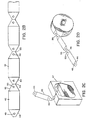
- Fig. 1 illustrates a radiation detector for tympanic temperature measurements in accordance with the present invention.
- Fig. 2A is an illustration of a disposable sheet for covering a probe of the detector of Fig. 1;
- Fig. 2B is an illustration of a tape of the disposable sheets of Fig. 2A;
- Fig. 2C is a perspective view of a carton containing a stack of the sheets formed by a z fold of the tape of Fig. 2B; and
- Fig. 2D is an illustration of a roll of such sheets.
- Fig. 3A is a side illustration of the sheet of Fig. 2A pulled over the probe of the radiation detector of Fig. 1; and Fig. 3B is a view of the sheet over the probe as viewed from line B-B of Fig. 3A.
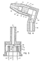
- Fig. 4 is a cross-sectional view of the extensions of the detector of Fig. 1 in which the thermopile radiation sensor is positioned.
- Fig. 5 is a cross-sectional view of the thermopile assembly of Fig. 4.
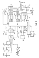
- Fig. 6 is a block diagram of the electronic circuit of the detector of Fig. 1.
- Fig. 7 illustrates a boot positioned on the detector of Fig. 1 during a calibration procedure.
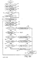
- Figs. 8A-8D are flow charts of the system firmware.
- the radiation detector 12 of Fig. 1 includes a flat housing 14 with a digital display 16 for displaying a tympanic temperature measurement.
- the display may be located anywhere on the housing, it is preferred that it be positioned on the end so the user is not inclined to watch it during a measurement.
- the instrument makes an accurate measurement when rotated to scan the ear canal, and the user should concentrate on only the scanning motion. Then the display can be read.
- a thermopile radiation sensor is supported within a probe 18 at the opposite end of the housing 14.
- the extension 18 extends orthogonally from an intermediate extension 20 which extends at an angle of about 15 degrees from the housing 14.
- the head of the detector, including the extension 18 and 20 has the appearance of a conventional otoscope.
- An on/off switch 22 is positioned on the housing.
- FIG. 4 A cross-sectional view of the extension of the detector is illustrated in Fig. 4.
- a base portion 22 is positioned within the housing 14, and the housing clamps about a groove 24.
- the portion 20 extends at about a 15 degree angle from the housing and thus from the base portion 22.
- the extension 18 is tapered toward its distal end at 26 so that it may be comfortably positoned in the ear to view the tympanic membrane and/or ear canal.
- a preferred disposable element to be used over the extension 18 is illustrated in Fig. 2A. It is a flat sheet 42 of 0.0127 mm (one-half mil) stretchable plastic such as polyethylene which is transparent to infrared . Reinforcement sheets 44 and 46 are provided at each end of the plastic sheet, and holes 48 and 50 are provided in the reinforced regions.
- the flat sheet may be stretched over the distal end of the extension 18 and pressed over retainers such as pins 52 and 54 protruding from the sides of the extension 18 as illustrated in Fig. 3A and 3B.
- retainers such as pins 52 and 54 protruding from the sides of the extension 18 as illustrated in Fig. 3A and 3B.
- a material to which polyethylene adheres may be provided on the probe to retain the sheet.
- the flat sheet does not provide a close fit to the sides over the full length of the extension 18, it is sufficiently stretchable to form a neat fit at the end of the extension and is sufficiently flexible that it bends and causes no discomfort to the patient when the extension is seated in the ear.
- the reinforcement sheets 44 and 46 serve as tabs which extend beyond the probe. Those tabs can be readily grasped for positioning the sheet on the probe and removing the sheet from the probe. Although the disposable cover could be formed without the reinforcement sheets, the stiffer reinforcement sheets make the disposable cover much easier to handle.
- the diameter of the end of the probe is about 9.525 mm (3/8 inch), and the sheet 42 is about 50.8 mm (two inches) wide so that it folds over the probe end when stretched.
- the distance between the holes is about 114.3 mm (41 ⁇ 2 inches) and that distance requires about 3.175 mm (1/8 inch) stretching of the sheet so secure it on the probe.
- the edge at the end of the probe is rounded so that when the probe is inserted into the ear it can be rotated somewhat without discomfort to the patient.
- the probe is also curved like an otoscope to avoid interference with the ear. By thus rotating the probe, the ear canal is scanned and, at some orientation of the probe during that scan, one can be assured that the maximum temperature is viewed. Since the ear canal cavity leading to the tympanic area is the area of highest temperature, the instrument is set in a peak detection mode, and the peak detected during the scan is taken as the tympanic temperature.
- An infrared reading of tympanic temperature allows for a very inexpensive disposable.
- the disposable need not be sufficiently rugged to prevent cutting by teeth and the resultant contamination as is the case with an oral thermometer.
- individual sheets are torn from a tape of sheets illustrated in Fig. 2B.
- Sheets are formed from a continuous tape of polyethylene.
- Adhesive tape is placed periodically along the tape to provide reinforcements.
- the tape is stamped to provide the levels at the ends of each sheet and to provide the holes 48 and 50.
- the reinforcement tape and polyethylene may be perforated at 55 to facilitate tearing of individual sheets from the tape.
- the tape may be folded in a z-fold fashion to form a stack of the disposable sheets packaged in a carton 57. As each cover is torn off, another appears.
- the tape may be provided in a roll as illustrated in Fig. 2D.
- the roll may also be placed in a carton.
- the carton may be provided with adhesive so that it can be mounted to the side of the housing 14 in an approach like that used with electronic thermometers.
- thermopile 28 is positioned within a can 30 to view the infrared radiation in the ear canal through a tube 32.
- Both the base can 30 and the tube 32 are in close thermal contact with a conductive thermal mass including an annular member 34 and a plug 36 of copper.
- the outer sleeve 38 of the extension 18 and the intermediate extension 20 are of plastic material of low thermal conductivity.
- the sleeve 38 is separated from the thermal mass 34 by an insulating air space 40.
- the taper of the thermal mass 34 permits the insulating space to the end of the extension while minimizing the thermal resistance from the end of the tube 32 to the thermopile, a parameter discussed in detail below.
- the inner surface of the plastic sleeve 38 may be coated with a good thermal conductor to distribute across the entire sleeve any heat received from contact with the ear. 0.508 mm (twenty mils) of copper coating would be suitable.
- thermopile assembly within the can 30 Details of the thermopile assembly within the can 30 are illustrated in Fig. 5.
- the tube 32 and can cylinder 30 are soldered together to form an integral unit in which a gaseous medium of low thermal conductivity such as xenon fills the tube and cylinder 30 and surrounds a thermopile flake 28.
- the tube is closed by a germanium window 57.
- the interior of the tube is plated with gold to improve its reflectance to better guide radiation to the flake.
- thermopile assembly with a window on the can and to position the waveguide tube in front of the can.
- a rigid window should be placed at the distal end of the tube. Two windows would diminish the radiation signal received by the thermopile.
- thermopile is mounted to the rear surface of a polyester sheet 58 (sold under the trademark Mylar) supported on the rear surface of a beryllium oxide ring 60.
- Contact to the thermopile is made through pins 62 and 64 which extend through a stack of beryllium oxide rings 66.
- Beryllium oxide is used because it is an electrical insulator yet a good thermal conductor.
- a case conductor 68 contacts the casing.
- Connection to the thermopile is by a conductive film printed on the sheet 58. To prevent abrasion of that film, the ring 60 is usually spaced slightly from the adjacent ring 66.
- space 70 is filled with a conductive material. It is preferable that the material be filled with an epoxy of good thermal conductivity, but virtually any material offers a substantial improvement over the lack of conduction through the xenon.
- thermopile One of the design goals of the device was that it always be in proper calibration without requiring a warm-up time. This precluded the use a heated target in a chopper unit or heating of the cold junction of the thermopile as was suggested in the above-mentioned O'Hara et al. patent. To accomplish this design goal, it is necessary that the system be able to operate with the thermopile at any of a wide range of ambient temperatures and that the thermopile output have very low sensitivity to any thermal perturbations.
- thermopile The output of the thermopile is a function of the difference in temperature between its warm junction, heated by radiation, and its cold junction which is in close thermal contact with the can 30.
- the hot junction respond only to radiation viewed through the window 57, it is important that the tube 32 be, throughout a measurement, at the same temperature as the cold junction. To that end, changes in temperature in the tube 32 must be held to a minimum, and any such changes should be distributed rapidly to the cold junction to avoid any thermal gradients.
- the tube 32 and the can 30 are, of course, well insulated by means of the volume of air 40. Further, a high conductance thermal path is provided to the cold junction.
- the tube 32 and can 30 are in close thermal communication with the thermal masses 34 and 36, and the high conductivity and thickness of the thermal masses increase the thermal conductance.
- a high thermal conductivity epoxy, solder or the like joins the tube, can and thermal masses.
- the solder or epoxy provides a significant reduction in thermal resistance. Where solder is used, to avoid damage to the thermopile which is rated to temperatures of 125°C, a low temperature solder of indium-tin alloy which flows at 100°C is allowed to flow into the annular mass 34 to provide good thermal coupling between all elements.
- the thermal resistance from the outer surface of the plastic sleeve 38 to the conductive thermal mass is high to minimize thermal perturbations to the inner thermal mass.
- the thermal mass of the tube 32, can 30, annular mass 34 and plug 36 should be large.
- the thermal resistance between any two points of the thermal mass should be low.
- any external thermal disturbances such as when the extension contacts skin, only reach the conductive thermal mass at extremely low levels during a measurement period of a few seconds; due to the large thermal mass of the material in contact with the cold junction, any such heat transfer only causes small changes in temperature; and due to the good thermal conductance throughout the thermal mass, any changes in temperature are distributed quickly and are reflected in the cold junction temperature quickly so that they do not affect temperature readings.
- the thermal RC time constant for thermal conduction through the thermal barrier to the thermal mass and tube should be at least two orders of magnitude greater than the thermal RC time constant for the temperature response of the cold junction to heat transferred to the tube and thermal mass.
- the RC time constant for conduction through the thermal barrier is made large by the large thermal resistance through the thermal barrier and by the large thermal capacitance of the thermal mass.
- the RC time constant for response of the cold junction is made low by the low resistance path to the cold junction through the highly conductive copper tube, can and thermal mass, and the low thermal capacitance of the stack of beryllium oxide rings and pin conductors to the thermopile.
- the thermal resistance through the thermal barrier and the internal thermal resistance can be increased by increased radial dimensions
- the capacitance of the thermal mass can be increased by increasing its size
- the thermal resistance through the longitudinal thermal path through the tube can be decreased by increasing its size.
- the size must be limited to permit the extension to be readily positioned and manipulated within the ear.
- leads to the system are kept to small diameters. Further, they are embedded in the plug 36 through bores 70; thus, any heat brought into the system through those leads is quickly distributed throughout the thermal mass, and only small changes in temperature and small gradients result.
- thermopile 28 Because the temperature of the thermal mass is not controlled, and the response of the thermopile 28 is a function of its cold junction temperature, the cold junction temperature must be monitored. To that end, a thermistor is positioned at the end of a central bore 72 in the plug 36.
- FIG. 6 A schematic illustration of the electronics in the housing 14, for providing a temperature readout on display 16 in response to the signal from the thermopile, is presented in Fig. 6.
- the system is based on a microprocessor 73 which processes software routines included in read only memory within the processor chip.
- the processor may be a 6805 processor sold by Motorola.
- the voltage generated across the thermopile 28 due to a temperature differential between the hot and cold junctions is amplified in an operational amplifier 74.
- the analog output from the amplifier 74 is applied as one input to a multiplexer 76.
- Another input to the multiplexer 76 is a voltage taken from a voltage divider R1, R2 which is indicative of the potential V+ from the power supply 78.
- a third input to the multiplexer 76 is the potential across a thermistor RT1 mounted in the bore 72 of block 36.
- the thermistor RT1 is coupled in a voltage divider circuit with R3 across a reference potential VRef.
- the final input to the multiplexer is a potential taken from a potentiometer R4 which may be adjusted by a user.
- the system may be programmed to respond to that input in any of a number of ways.
- the potentiometer may be used as a gain control or as a DC offset control.
- one of the four inputs may be selected by the select lines 78.
- the selected analog signal is applied to a multiple slope analog system 80 used by the microprocessor in an integrating analog-to-digital conversion 80.
- the subsystem 80 may be a TSC500A sold by Teledyne. It utilizes the reference voltage VRef from a reference source 82.
- the microprocessor 73 responds to the output from the convertor 80 to generate a count indicative of the analog input to the convertor.
- the microprocessor drives four 7-segment LED displays 82 in a multiplexed fashion. Individual displays are selected sequentially through a column driver 84, and within each selected display the seven segments are controlled through segment drivers 86.
- the switch 22 on the housing When the switch 22 on the housing is pressed, it closes the circuit from the battery 78 through resistors R5 and R6 and diode D1 to ground. The capacitor C1 is quickly charged, and field effect transistor T1 is turned on. Through transistor T1, the V+ potential from the storage cell 78 is applied to a voltage regulator 88.
- the regulator 88 provides the regulated +5 volts to the system. It also provides a reset signal to the microprocessor. The reset signal is low until the +5 volt reference is available and thus holds the microprocessor in a reset state. When the +5 volts is available, the reset signal goes high, and the microprocessor begins its programmed routine.
- the switch 22 When the switch 22 is released, it opens its circuit, but a charge is maintained on capacitor C1 to keep transistor T1 on. Thus, the system continues to operate. However, the capacitor C1 and transistor T1 provide a very simple watchdog circuit. Periodically, the microprocessor applies a signal through driver 84 to the capacitor C1 to recharge the capacitor and thus keep the transistor T1 on. If the microprocessor should fail to continue its programmed routine, it fails to charge the capacitor C1 within a predetermined time during which the charge on C1 leaks to a level at which transistor T1 turns off. Thus, the microprocessor must continue in its programmed routine or the system shuts down. This prevents spurious readings when the processor is not operating properly.
- the switch 22 can be used as an input through diode D2 to the microprocessor to initiate any programmed action of the processor.
- the system has a sound output 90 which is driven through the driver 84 by the microprocessor.
- a digital-to-analog convertor 92 is provided. When selected by line 94, the convertor converts serial data on line 96 to an analog output made available to a user.
- both calibration and characterization data required for processing by the microprocessor may be stored in an electrically erasable programmable read only memory (EEPROM) 100.
- the EEPROM may, for example, be a 93c46 sold by International CMOS Technologies, Inc.
- the data may be stored in the EEPROM by the microprocessor when the EEPROM is selected by line 102. Once stored in the EEPROM, the data is retained even after power down. Thus, though electrically programmable, once programmed the EEPROM serves as a virtually nonvolatile memory.
- the EEPROM may be programmed through the microprocessor to store calibration data for calibrating the thermistor and thermopile. Further., characterization data which defines the personality of the infrared detector may be stored. For example, the same electronics hardware, including the microprocessor 73 and its internal program, may be used for a tympanic temperature detector in which the output is accurate in the target temperature range of about 15.56°C to 44.33°C (60°F to 110°F). Further, different modes of operation may be programmed into the system. For example, several different uses of the sound source 90 are available.
- a communication boot 104 may be placed over the end of the detector during a calibration/characterization procedure.
- a photodiode in the boot generates a digitally encoded optical signal which is filtered and applied to the detector T2 to provide an input to the microprocessor 73.
- the microprocessor may communicate optically to a detector in the boot by flashing specific segments of the digital display 82.
- an outside computer 106 can monitor the outputs from the thermistor and thermopile and perform a calibration of the devices.
- a unit to be calibrated is pointed at each of two black body radiation sources while the microprocessor 73 converts the signals and sends the values to the external computer.
- the computer is provided with the actual black body temperatures and ambient temperature in the controlled environment of the detector, computes calibration variables and returns those variable to be stored in the detector EEPROM. Similarly, data which characterizes a particular radiation detector may be communicated to the microprocessor for storage in the EEPROM.
- a switch 108 is positioned behind a hole 109 (Fig. 1) in the radiation detector so that it may be actuated by a rigid metal wire or pin. Through that switch, the user may control some specific mode of operation such as converting the detector from degrees Fahrenheit to degrees centigrade. That mode of operation may be stored by the microprocessor 73 in the EEPROM so that the detector continues to operate in a specific mode until a change is indicated by closing the switch 108.
- a switch 108 may be provided either internally or through the housing to the user to set a mode of operation of the detector. By positioning the switch at either the lock position, the scan position or a neutral position, any of three modes may be selected.
- the first mode is the normal scan mode where the display is updated continuously.
- a second mode is a lock mode where the display locks after a selectable delay and then remains frozen until power is cycled or, optionally, the power-on button is pushed.
- the sound source may be caused to sound at the time of lock.
- the third mode is the peak mode where the display reads the maximum value found since power-on until power is cycled or, optionally, the power-on button is pushed.
- the processor determines when the voltage from the divider R1, R2 drops below each of two thresholds. Below the higher threshold, the processor periodically enables the sound source to indicate that the battery is low and should be replaced but allows continued readout from the display. Below the lower threshold, the processor determines that any output would be unreliable and no longer displays temperature readings. The unit would then shut down upon release of the power button.
- a fourth power representation of the ambient temperature is then obtained by a lookup table in the processor ROM.
- the sensed radiation may be corrected using a calibration factor, a sensor gain temperature coefficient, the detected ambient temperature and a calibration temperature stored in the EEPROM.
- the corrected radiation signal and the fourth power of the ambient temperature are summed, and the fourth root is taken.
- the fourth root calculation is also based on a linear approximation which is selected according to the temperature range of interest for a particular unit. Again, the break points and coefficients for each linear approximation are stored in the EEPROM and are selected as required.
- To the thus computed target temperature is added an adjustment factor which allows for a reading which closely corresponds to core temperature based on the knowledge of the relationship of core temperature to tympanic temperature. Also added to the calculated temperature is a user tweak obtained from resistor R4.
- T e Te - cT amb (1-c) This computation can account for a difference of from one-half to one degree between core temperature and sensed ear temperature, depending on ambient temperature.
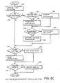
- Figs. 8A-8D provide a flowchart of the firmware stored in the microprocessor 73. From reset when the instrument is turned on, the system is initialized at 110 and the contents of the EEPROM are read into memory in the microprocessor at 112. At 114, the processor reads the state of power and mode switches in the system. At 116, the system determines whether a mode switch 113 has placed the system in a self-test mode. If not, all eights are displayed on the four-digit display 82 for a brief time. At 120, the system performs all A-to-D conversions to obtain digital representations of the thermopile output and the potentiometer settings through multiplexor 76.
- the system then enters a loop in which outputs dictated by the mode switch are maintained. First the timers are updated at 122 and the switches are again read at 124. When the power is switched off, from 126 the system enters a power down loop at 128 until the system is fully down. At 130, the mode switch is checked and if changed the system is reset. Although not in the tympanic temperature detector, some detectors have a mode switch available to the user so that the mode of operation can be changed within a loop.
- the system determines its mode of operation and enters the appropriate scan process 134, lock process 138 or peak process 142.
- a scan process the system updates the output to the current reading in each loop.
- a lock process the system updates the output but locks onto an output after some period of time.
- the peak process the system output is the highest indication noted during a scan.
- the system may respond to the programming from the EEPROM to perform any number of functions as discussed above.
- the peak process which is selected for the tympanic temperature measurement, the system locks onto a peak measurement after a preset period of time.
- the system may be set at a test mode 144 which will be described with respect to Fig. 8D.
- an output is calculated at 146. Then the system loops back to step 122.
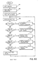
- the calculation 146 is illustrated in Fig. 8B.
- the raw sensor data is obtained from memory.
- the sensor offset taken from the EEPROM is subtracted at 150, and the ambient temperature previously obtained from the potentiometer RT1 is accessed at 152.
- the temperature coefficient adjustment is calculated at 154.
- the sensed signal is multiplied by the gain from EEPROM and by the temperature coefficient.
- the fourth power of the ambient temperature is obtained, and at 160 it is added to the sensor signal.
- the fourth root of the sum is obtained through a lookup table. Whether the display is in degrees centigrade or degrees Fahrenheit is determined at 164. If in degrees centrigrade, a conversion is performed at 166.
- adjustment values including that from the potentiometer R4, are added.
- Analog-to-Digital conversion is performed periodically during an interrupt to the loop of Fig. 8A which occurs every two milliseconds.
- the interrupt routine is illustrated in Fig. 8C.
- Timer counters are updated at 170.
- A-to-D conversions are made from 172 only every 100 milliseconds when a flag has been set in the prior interrupt cycle. During most interrupts, an A/D conversion does not occur.
- the 100-millisecond counter is checked at 174, and if the count has expired, a flag is set at 176 for the next interrupt. The flag is checked at 178 and, if found, the display is updated at 180. The system then returns to the main loop of Fig. 8A.
- thermopile sensor conversion is performed nine out of ten cycles through the conversion loop.
- the system checks to determine whether a conversion is made from the potentiometer R4 or from the battery voltage divider R1, R2 at 192. These conversions are made alternately.
- Fig. 8D illustrates the self-test sequence which is called by the mode switch 113 only during assembly.
- the beeper sounds at 182 and all display segments are displayed at 184.
- the system steps each character of the display from zero through nine at 186.
- the system then enters a test loop.
- the system senses whether the button 108 has been pressed. If so, a display counter is incremented at 190.
- the display for the unit then depends on the count of the display counter. With the zero count, the adjustment potentiometer value is displayed at 192.
- the display counter is incremented by pressing the button 108, the raw sensor data is displayed. With the next increment, ambient temperature is displayed at 196, and with the next increment, the raw output from the ambient temperature sensor RT1 is displayed. With the next increment, the battery voltage is displayed.
- the assembler sets the mode switch to the proper operating mode.
Abstract
Description
- The most common way of measuring a patient's temperature is by use of a sublingual thermometer, that is, one placed under the tongue. Such thermometers have suffered several disadvantages. Accuracy of a reading depends on the mouth remaining closed and the thermometer being properly positioned under the tongue. Drinking liquids or breathing through the mouth prior to taking a measurement can affect the reading. Further, the mouth is a source of mucous which presents a significant risk of cross-contamination. Also, the cost per reading of such instruments has typically been high.
- One type of sublingual thermometer is the common mercury thermometer. Such thermometers have the disadvantage of taking a considerable amount of time to reach a steady state temperature in order to provide an accurate reading. Further, they are easily broken, require sterilization, and are difficult to read.
- As an alternative to the mercury thermometer, disposable liquid crystal thermometers are often favored. As a disposable item, the sterilization requirement is eliminated, but the cost per reading is high.
- To decrease the time required to obtain a patient's temperature, electronic thermometers have been developed. Such thermometers typically include a thermistor which may be positioned in a disposable cover. Although the thermometers do not reach a steady state temperature during their measurement time of 15 to 30 seconds, through electronic interpolation a steady state temperature may be estimated from the temperature readings throughout the 15 to 30 seconds. The thermometers are often cumbersome, and as with other sublingual thermometers the temperature readings may be unreliable in certain circumstances, especially when the probe is not precisely placed under the tongue.
- Another electronic temperature device is a tympanic temperature measurement device. Such devices rely on a measurement of the temperature of the tympanic membrane area in the ear by detection of infrared radiation. The tympanic membrane area is often considered to be more representative of a patient's core temperature, and infrared temperature measurements using a thermopile are extremely rapid. Disposable sleeves may be placed over the radiation detector. A commercial tympanic temperature measurement device is illustrated in US-A-4,602,642 to O'Hara et al. As suggested in that patent, the infrared detection approach does present demands on the instrumentation to avoid inaccuracies due to ambient temperature and spurious heat flux to the thermopile.
- A method of measuring body temperature is also disclosed in US-A- 3,282,106. That method comprises aiming an infrared radiometer having radiation detecting means responsive to infrared for radiations from a 300 K black body into a body cavity the surrounding tissues of which are isolated from environmental temperature changes and surround sufficiently to produce multiple reflections whereby the cavity, as a whole, radiates as a black body and reading temperature from the output of said radiometer.
- GB-1425765 discloses a replaceable cap for a sensing probe of an electronic device for measuring body temperature.
- EP-A-0092535 discloses a fever thermometer protector consisting of an expansible plastic film to which a dimensionally stable backing means has been attached.
- EP-A-0201790 discloses a sanitary protective cover or sheath for an ear canal probe of a tympanic thermometer.
- US-A-4784149 discloses a thermometer for measuring the infrared radiation emitted from the tissue surface of a body cavity.
- The present invention relates to various features of a radiation detector which make the detector particularly suited to tympanic temperature measurements without certain deficiencies of prior tympanic temperature detectors. For example, the O'Hara et al. system relies on heating of the radiation probe to a precise temperature to maintain calibration of the device during a test. As a result, the instrument is not usable where the ambient temperature exceeds that precise temperature. Also, to assure proper calibration for each test, the O'Hara et al. system uses a light chopper-type of calibration unit having a target heated to approximately 36.67 (98°F). Before each test, the thermopile in the probe is calibrated as it views the chopper unit target. Once removed from the chopper, the temperature reading must be obtained promptly because the probe will cool after removal from the unit and thus introduce errors. This requirement for calibration in the chopper unit prior to each temperature reading imposes a rigid protocol on the user which is more cumbersome than that of electronic thermometers. Further, the requirement for heating the target and the probe adds bulk and weight to the system. In practice, the temperature of greater interest to a medical practitioner is most often that of internal temperature, which has heretofore only been detected by invasive means. The applicant has recognised that the temperature of the tissue being viewed by a radiation detector is a function of that internal temperature and of the ambient temperature to which the tissue is exposed. Accordingly, the internal temperature can be determined by using ambient temperature to compensate the actual tissue temperature.
- The present invention provides a temperature detector, comprising: a housing adapted to be held by hand; an extension from the housing, the extension passing radiation from a target surface to a radiation sensor; a temperature display for displaying temperature; and electronics in the housing for converting radiation sensed by the sensor to temperature displayed by the display; characterised in that the temperature display is on the housing and an internal temperature approximation is displayed, the electronics providing the internal temperature displayed on the display as a function of the sensed temperature indicated by the received radiation, compensated by an ambient temperature signal obtained by a temperature sensor, the function defining the internal temperature relative to the sensed temperature indicated by the received radiation and ambient temperature with assumed thermal resistances between the internal temperature and sensed temperature and between the sensed temperature and ambient temperature, thereby to provide an internal temperature approximation of a body which is internal to the target surface from which radiation is sensed by the radiation sensor.
- The present invention also provides method of determining temperature, comprising the steps of: providing a radiation detector comprising an extension for passing infrared radiation from an external target surface to a sensor and electronics for converting radiation sensed by the sensor to temperature; and detecting the radiation; characterised in that the method further comprises the step of approximating an internal temperature by compensating the sensed temperature indicated by the received radiation as a function of an ambient temperature signal obtained by a temperature sensor, the function defining the internal temperature relative to the sensed temperature indicated by the received radiation and ambient temperature, with assumed thermal resistances between the internal temperature and sensed temperature and between the sensed temperature and ambient temperature, thereby to provide an approximation of the temperature of a body which is internal to the target surface from which radiation is sensed by the sensor.
- The present invention further provides a temperature detector, comprising: a housing; a probe for passing radiation from a target surface to a radiation sensor; a temperature display on the housing for displaying temperature; and electronics in the housing for converting radiation sensed by the sensor to temperature displayed by the display; characterised in that the electronics include a radiation peak detector such that a peak temperature is displayed with movement of the probe relative to the target surface; the housing is adapted to be held by hand; and the probe is an extension from the housing.
- The present invention still further provides a method of determining temperature, comprising the steps of: providing a radiation detector comprising an extension for passing infrared radiation from an external target to a sensor and electronics for converting the radiation sensed by the sensor to temperature; and detecting the radiation; characterised in that the method further comprises the step of scanning a target surface with the radiation detection, the sensor sensing radiation during scanning, and determining the peak radiation sensed by the sensor and converting the peak radiation sensed to a peak temperature.
- In accordance with one preferred aspect of the present invention, a thermopile is mounted within a thermal mass and has a junction thermally coupled to the thermal mass. A thermally conductive, reflective tube is coupled to the thermal mass for guiding radiation to the thermopile from an external target. A thermal barrier surrounds the thermal mass and tube. The temperature of the thermal mass, and thus of the thermopile cold junction, is allowed to float with ambient. A temperature measurement of the thermal mass is made to compensate the thermopile output.
- Temperature differences between the tube and thermopile cold junction would lead to inaccurate readings. To avoid those differences, the large thermal mass minimizes temperature changes from heat which passes through the thermal barrier, and good conductivity within the mass increases conductance and minimizes temperature gradients. The outer thermal RC time constant for thermal conduction through the thermal barrier to the thermal mass and tube is at least two, and preferably at least three, orders of magnitude greater than the inner thermal RC time constant for the temperature response of the cold junction to heat transferred to the tube and thermal mass. For prompt readings, the inner RC time constant should be about 1/2 second or less.
- Preferably, the thermopile is mounted to a film suspended within a ring. The ring is supported on electrically conductive pins extended through an adjacent ring to the side of the film on which the thermopile is mounted. The film is spaced from the adjacent ring, and the rings and thermopile are surrounded by a low conductivity gaseous volume. Preferably, the low conductivity gaseous volume extends through the length of the conductive tube. The space between the film and the adjacent ring through which the conductors extend is filled with thermally conductive material.
- The thermopile may be mounted in a can which encloses the low conductivity gaseous volume. The thermal mass may comprise an annular member which surrounds the can and a length of the tube adjacent to the can. The annular member is tapered about its outer periphery toward the tube. A conductive plug is positioned behind the can within the annular member. The can, tube, annular member and plug are bonded together by high thermal conductivity material such as solder, epoxy, or powdered metal to obtain a continuous low resistance path from the end of the tube to the cold junction of the thermopile. Alternatively, the parts may be press fit together to provide the high conductance bond. The thermal barrier comprises a sleeve spaced from the thermal mass and tube. The sleeve is tapered toward the end of the tube away from the can.
- Preferably, a probe extension which supports the radiation sensor extends from a housing which displays the tympanic temperature. This housing supports battery powered electronics for converting radiation sensed by the sensor to tympanic temperature displayed by the display. The entire instrument may be housed in a single hand-held package because a chopper calibration unit is not required. The small additional weight of the electronics in the hand-held unit is acceptable because readings can be made quickly. The readings can be made in less than five seconds, and preferably in less than two seconds.
- Preferably, the probe extension extends about orthogonally from an intermediate extension which extends at an angle of about 15° from an end of the housing. The surface of the extension curves outwardly along its length from its distal end following a curve similar to that of an otoscope. A sanitary cover in the form of a removeable plastic sheet may be stretched over the end of the probe. The sheet may be retained on the probe by posts on the sides of the probe over which holes in the sheet are positioned.
- Many of the sheets can be formed in a tape of transparent, flexible membrane segmented into individual covers by frangible lengths across the tape. The holes adapted to retain the sheet across the probe are formed to each side of each frangible length. Reinforcement tape may be positioned on the tape, and the frangible lengths may be formed as by perforations through the reinforcement tapes. In the present application, the membrane must be transparent to infrared radiation. The covers may be adapted to other measuring instruments by using membranes which are transparent, for example, to visual light, sound or the like. Polyethylene sheet is preferred for infrared measurements.
- The electronics may include an optical signal detector for receiving a digital input, and an electrically erasable programmable read only memory (EEPROM). A processor is programmed to respond to input from the optical signal detector to store information in the EEPROM and to use the stored information to respond to radiation and to drive the display. The processor may also be programmed to operate in a communications mode in which it transfers information to an external optical signal detector by modulation of the display. Communications may be with an external computer through a boot which fits over the display during calibration.
- The information stored in the EEPROM may include calibration information. It may also establish a range and incremental response of the display to sensed radiation and other information which characterizes the personality of a particular unit. For example, the information stored in the EEPROM may determine whether the display is in degrees Fahrenheit or degrees centigrade. That information may be controlled by a switch to which the processor responds. The system may include a sound source, and the stored information may determine the timing at which the sound source is activated. For example, the stored information may cause the display to be locked to a reading a predetermined time after the radiation detector is turned on, and the stored information may cause the sound source to be activated when the display is locked. Similarly, the stored information may cause the radiation detector to be turned off after a predetermined time and cause the sound source to be activated as the radiation detector is turned off. Alternatively, the stored information may cause the display to indicate the peak radiation sensed during a period of time and may cause the sound source to be activated when radiation sensed by the sensor approximates the peak.
- The information stored in the EEPROM causes a conversion from sensed tympanic temperature to a temperature which approximates core temperature and that approximated core temperature is displayed. The processor may also perform conversions based on linear approximations, and the stored information may establish the end points and slopes of the linear approximations. For example, a linear approximation may be used to determine ambient temperature from a thermistor output or to determine target temperature from a thermistor output and a thermopile output.
- The electronics support a simple watchdog operation associated with the on switch to the unit. An active device is turned on by the switch to apply power to the electronics. A capacitor stores, for a limited time, a charge which holds the active device after release of the switch. The processor is programmed to periodically charge the capacitor after power is applied through the active device. Failure of the processor to follow a program routine results in discharge of the capacitor and turning off of the active device on the radiation detector. The switch may also be coupled directly to the processor so that the processor may respond to actuation of the switch after the radiation detector is turned on for other functions.
- Preferred embodiments of the present invention will now be described hereinbelow by way of example only with reference to the accompanying drawings.
- In the accompanying drawings like reference characters refer to the same parts throughout the different views. The drawings are not necessarily to scale, emphasis instead being placed upon illustrating the principles of the invention.
- Fig. 1 illustrates a radiation detector for tympanic temperature measurements in accordance with the present invention.
- Fig. 2A is an illustration of a disposable sheet for covering a probe of the detector of Fig. 1; Fig. 2B is an illustration of a tape of the disposable sheets of Fig. 2A; Fig. 2C is a perspective view of a carton containing a stack of the sheets formed by a z fold of the tape of Fig. 2B; and Fig. 2D is an illustration of a roll of such sheets.
- Fig. 3A is a side illustration of the sheet of Fig. 2A pulled over the probe of the radiation detector of Fig. 1; and Fig. 3B is a view of the sheet over the probe as viewed from line B-B of Fig. 3A.
- Fig. 4 is a cross-sectional view of the extensions of the detector of Fig. 1 in which the thermopile radiation sensor is positioned.
- Fig. 5 is a cross-sectional view of the thermopile assembly of Fig. 4.
- Fig. 6 is a block diagram of the electronic circuit of the detector of Fig. 1.
- Fig. 7 illustrates a boot positioned on the detector of Fig. 1 during a calibration procedure.
- Figs. 8A-8D are flow charts of the system firmware.
- The
radiation detector 12 of Fig. 1 includes aflat housing 14 with adigital display 16 for displaying a tympanic temperature measurement. Although the display may be located anywhere on the housing, it is preferred that it be positioned on the end so the user is not inclined to watch it during a measurement. The instrument makes an accurate measurement when rotated to scan the ear canal, and the user should concentrate on only the scanning motion. Then the display can be read. A thermopile radiation sensor is supported within aprobe 18 at the opposite end of thehousing 14. Theextension 18 extends orthogonally from anintermediate extension 20 which extends at an angle of about 15 degrees from thehousing 14. As such, the head of the detector, including theextension switch 22 is positioned on the housing. - A cross-sectional view of the extension of the detector is illustrated in Fig. 4. A
base portion 22 is positioned within thehousing 14, and the housing clamps about agroove 24. As noted, theportion 20 extends at about a 15 degree angle from the housing and thus from thebase portion 22. Theextension 18 is tapered toward its distal end at 26 so that it may be comfortably positoned in the ear to view the tympanic membrane and/or ear canal. - A preferred disposable element to be used over the
extension 18 is illustrated in Fig. 2A. It is aflat sheet 42 of 0.0127 mm (one-half mil) stretchable plastic such as polyethylene which is transparent to infrared .Reinforcement sheets extension 18 and pressed over retainers such aspins extension 18 as illustrated in Fig. 3A and 3B. Alternatively, a material to which polyethylene adheres may be provided on the probe to retain the sheet. Although the flat sheet does not provide a close fit to the sides over the full length of theextension 18, it is sufficiently stretchable to form a neat fit at the end of the extension and is sufficiently flexible that it bends and causes no discomfort to the patient when the extension is seated in the ear. - The
reinforcement sheets - The diameter of the end of the probe is about 9.525 mm (3/8 inch), and the
sheet 42 is about 50.8 mm (two inches) wide so that it folds over the probe end when stretched. The distance between the holes is about 114.3 mm (4½ inches) and that distance requires about 3.175 mm (1/8 inch) stretching of the sheet so secure it on the probe. - The edge at the end of the probe is rounded so that when the probe is inserted into the ear it can be rotated somewhat without discomfort to the patient. The probe is also curved like an otoscope to avoid interference with the ear. By thus rotating the probe, the ear canal is scanned and, at some orientation of the probe during that scan, one can be assured that the maximum temperature is viewed. Since the ear canal cavity leading to the tympanic area is the area of highest temperature, the instrument is set in a peak detection mode, and the peak detected during the scan is taken as the tympanic temperature.
- An infrared reading of tympanic temperature, as opposed to an electronic thermometer reading of oral temperature, allows for a very inexpensive disposable. The disposable need not be sufficiently rugged to prevent cutting by teeth and the resultant contamination as is the case with an oral thermometer.
- Preferably, individual sheets are torn from a tape of sheets illustrated in Fig. 2B. Sheets are formed from a continuous tape of polyethylene. Adhesive tape is placed periodically along the tape to provide reinforcements. The tape is stamped to provide the levels at the ends of each sheet and to provide the
holes - As illustrated in Fig. 2C, the tape may be folded in a z-fold fashion to form a stack of the disposable sheets packaged in a
carton 57. As each cover is torn off, another appears. Alternatively, the tape may be provided in a roll as illustrated in Fig. 2D. The roll may also be placed in a carton. In either case, the carton may be provided with adhesive so that it can be mounted to the side of thehousing 14 in an approach like that used with electronic thermometers. - As illustrated in Fig. 4, a
thermopile 28 is positioned within acan 30 to view the infrared radiation in the ear canal through atube 32. Both the base can 30 and thetube 32 are in close thermal contact with a conductive thermal mass including anannular member 34 and aplug 36 of copper. Theouter sleeve 38 of theextension 18 and theintermediate extension 20 are of plastic material of low thermal conductivity. Thesleeve 38 is separated from thethermal mass 34 by an insulatingair space 40. The taper of thethermal mass 34 permits the insulating space to the end of the extension while minimizing the thermal resistance from the end of thetube 32 to the thermopile, a parameter discussed in detail below. The inner surface of theplastic sleeve 38 may be coated with a good thermal conductor to distribute across the entire sleeve any heat received from contact with the ear. 0.508 mm (twenty mils) of copper coating would be suitable. - Details of the thermopile assembly within the
can 30 are illustrated in Fig. 5. Thetube 32 and cancylinder 30 are soldered together to form an integral unit in which a gaseous medium of low thermal conductivity such as xenon fills the tube andcylinder 30 and surrounds athermopile flake 28. The tube is closed by agermanium window 57. The interior of the tube is plated with gold to improve its reflectance to better guide radiation to the flake. - An alternative to forming the
tube 32 and can 30 as a single unit would be to use a conventional thermopile assembly with a window on the can and to position the waveguide tube in front of the can. However, to prevent contamination of the inner walls of the tube, a rigid window should be placed at the distal end of the tube. Two windows would diminish the radiation signal received by the thermopile. - The thermopile is mounted to the rear surface of a polyester sheet 58 (sold under the trademark Mylar) supported on the rear surface of a
beryllium oxide ring 60. Contact to the thermopile is made throughpins case conductor 68 contacts the casing. Connection to the thermopile is by a conductive film printed on thesheet 58. To prevent abrasion of that film, thering 60 is usually spaced slightly from theadjacent ring 66. As noted below, good thermal conduction is important in implementing the present invention, and it was found that the xenon gas filling the gap significantly reduced the conduction to the cold junction of the thermopile. In accordance with one feature of the present invention, thatspace 70 is filled with a conductive material. It is preferable that the material be filled with an epoxy of good thermal conductivity, but virtually any material offers a substantial improvement over the lack of conduction through the xenon. - One of the design goals of the device was that it always be in proper calibration without requiring a warm-up time. This precluded the use a heated target in a chopper unit or heating of the cold junction of the thermopile as was suggested in the above-mentioned O'Hara et al. patent. To accomplish this design goal, it is necessary that the system be able to operate with the thermopile at any of a wide range of ambient temperatures and that the thermopile output have very low sensitivity to any thermal perturbations.
- The output of the thermopile is a function of the difference in temperature between its warm junction, heated by radiation, and its cold junction which is in close thermal contact with the
can 30. In order that the hot junction respond only to radiation viewed through thewindow 57, it is important that thetube 32 be, throughout a measurement, at the same temperature as the cold junction. To that end, changes in temperature in thetube 32 must be held to a minimum, and any such changes should be distributed rapidly to the cold junction to avoid any thermal gradients. To minimize temperature changes, thetube 32 and thecan 30 are, of course, well insulated by means of the volume ofair 40. Further, a high conductance thermal path is provided to the cold junction. Thetube 32 and can 30 are in close thermal communication with thethermal masses annular mass 34 to provide good thermal coupling between all elements. - The thermal resistance from the outer surface of the
plastic sleeve 38 to the conductive thermal mass is high to minimize thermal perturbations to the inner thermal mass. To minimize changes in temperature of thetube 32 with any heat transfer to the tube which does occur, the thermal mass of thetube 32, can 30,annular mass 34 and plug 36 should be large. To minimize thermal gradients where there is some temperature change in the tube during measurement, the thermal resistance between any two points of the thermal mass should be low. - Thus, due to the large time constant of the thermal barrier, any external thermal disturbances, such as when the extension contacts skin, only reach the conductive thermal mass at extremely low levels during a measurement period of a few seconds; due to the large thermal mass of the material in contact with the cold junction, any such heat transfer only causes small changes in temperature; and due to the good thermal conductance throughout the thermal mass, any changes in temperature are distributed quickly and are reflected in the cold junction temperature quickly so that they do not affect temperature readings.
- The thermal RC time constant for thermal conduction through the thermal barrier to the thermal mass and tube should be at least two orders of magnitude greater than the thermal RC time constant for the temperature response of the cold junction to heat transferred to the tube and thermal mass. The RC time constant for conduction through the thermal barrier is made large by the large thermal resistance through the thermal barrier and by the large thermal capacitance of the thermal mass. The RC time constant for response of the cold junction is made low by the low resistance path to the cold junction through the highly conductive copper tube, can and thermal mass, and the low thermal capacitance of the stack of beryllium oxide rings and pin conductors to the thermopile.
- Although the cold junction capacitance is naturally low, there are size constraints in optimizing the thermal capacitance of the thermal mass, the thermal resistance through the thermal barrier and the internal thermal resistance. Specifically, the external thermal resistance can be increased by increased radial dimensions, the capacitance of the thermal mass can be increased by increasing its size, and the thermal resistance through the longitudinal thermal path through the tube can be decreased by increasing its size. On the other hand, the size must be limited to permit the extension to be readily positioned and manipulated within the ear.
- Besides the transfer of heat from the environment, another significant heat flow path to the conductive thermal mass is through leads to the system. To minimize heat transfer through that path, the leads are kept to small diameters. Further, they are embedded in the
plug 36 throughbores 70; thus, any heat brought into the system through those leads is quickly distributed throughout the thermal mass, and only small changes in temperature and small gradients result. - Because the temperature of the thermal mass is not controlled, and the response of the
thermopile 28 is a function of its cold junction temperature, the cold junction temperature must be monitored. To that end, a thermistor is positioned at the end of acentral bore 72 in theplug 36. - A schematic illustration of the electronics in the
housing 14, for providing a temperature readout ondisplay 16 in response to the signal from the thermopile, is presented in Fig. 6. The system is based on amicroprocessor 73 which processes software routines included in read only memory within the processor chip. The processor may be a 6805 processor sold by Motorola. - The voltage generated across the
thermopile 28 due to a temperature differential between the hot and cold junctions is amplified in anoperational amplifier 74. The analog output from theamplifier 74 is applied as one input to amultiplexer 76. Another input to themultiplexer 76 is a voltage taken from a voltage divider R1, R2 which is indicative of the potential V+ from thepower supply 78. A third input to themultiplexer 76 is the potential across a thermistor RT1 mounted in thebore 72 ofblock 36. The thermistor RT1 is coupled in a voltage divider circuit with R3 across a reference potential VRef. The final input to the multiplexer is a potential taken from a potentiometer R4 which may be adjusted by a user. The system may be programmed to respond to that input in any of a number of ways. In particular, the potentiometer may be used as a gain control or as a DC offset control. - At any time during the software routine of the
microprocessor 73, one of the four inputs may be selected by the select lines 78. The selected analog signal is applied to a multipleslope analog system 80 used by the microprocessor in an integrating analog-to-digital conversion 80. Thesubsystem 80 may be a TSC500A sold by Teledyne. It utilizes the reference voltage VRef from areference source 82. Themicroprocessor 73 responds to the output from theconvertor 80 to generate a count indicative of the analog input to the convertor. - The microprocessor drives four 7-segment LED displays 82 in a multiplexed fashion. Individual displays are selected sequentially through a
column driver 84, and within each selected display the seven segments are controlled throughsegment drivers 86. - When the
switch 22 on the housing is pressed, it closes the circuit from thebattery 78 through resistors R5 and R6 and diode D1 to ground. The capacitor C1 is quickly charged, and field effect transistor T1 is turned on. Through transistor T1, the V+ potential from thestorage cell 78 is applied to avoltage regulator 88. Theregulator 88 provides the regulated +5 volts to the system. It also provides a reset signal to the microprocessor. The reset signal is low until the +5 volt reference is available and thus holds the microprocessor in a reset state. When the +5 volts is available, the reset signal goes high, and the microprocessor begins its programmed routine. - When the
switch 22 is released, it opens its circuit, but a charge is maintained on capacitor C1 to keep transistor T1 on. Thus, the system continues to operate. However, the capacitor C1 and transistor T1 provide a very simple watchdog circuit. Periodically, the microprocessor applies a signal throughdriver 84 to the capacitor C1 to recharge the capacitor and thus keep the transistor T1 on. If the microprocessor should fail to continue its programmed routine, it fails to charge the capacitor C1 within a predetermined time during which the charge on C1 leaks to a level at which transistor T1 turns off. Thus, the microprocessor must continue in its programmed routine or the system shuts down. This prevents spurious readings when the processor is not operating properly. - With transistor T1 on, the
switch 22 can be used as an input through diode D2 to the microprocessor to initiate any programmed action of the processor. - In addition to the display, the system has a
sound output 90 which is driven through thedriver 84 by the microprocessor. - In order to provide an analog output from the detector, a digital-to-
analog convertor 92 is provided. When selected byline 94, the convertor converts serial data online 96 to an analog output made available to a user. - In accordance with one aspect of the present invention, both calibration and characterization data required for processing by the microprocessor may be stored in an electrically erasable programmable read only memory (EEPROM) 100. The EEPROM may, for example, be a 93c46 sold by International CMOS Technologies, Inc. The data may be stored in the EEPROM by the microprocessor when the EEPROM is selected by
line 102. Once stored in the EEPROM, the data is retained even after power down. Thus, though electrically programmable, once programmed the EEPROM serves as a virtually nonvolatile memory. - Prior to shipment, the EEPROM may be programmed through the microprocessor to store calibration data for calibrating the thermistor and thermopile. Further., characterization data which defines the personality of the infrared detector may be stored. For example, the same electronics hardware, including the
microprocessor 73 and its internal program, may be used for a tympanic temperature detector in which the output is accurate in the target temperature range of about 15.56°C to 44.33°C (60°F to 110°F). Further, different modes of operation may be programmed into the system. For example, several different uses of thesound source 90 are available. - Proper calibration of the detector is readily determined and the EEPROM is readily programmed by means of an optical communication link which includes a transistor T2 associated with the display. As illustrated in Fig. 7, a
communication boot 104 may be placed over the end of the detector during a calibration/characterization procedure. A photodiode in the boot generates a digitally encoded optical signal which is filtered and applied to the detector T2 to provide an input to themicroprocessor 73. In a reverse direction, the microprocessor, may communicate optically to a detector in the boot by flashing specific segments of thedigital display 82. Through that communication link, anoutside computer 106 can monitor the outputs from the thermistor and thermopile and perform a calibration of the devices. A unit to be calibrated is pointed at each of two black body radiation sources while themicroprocessor 73 converts the signals and sends the values to the external computer. The computer is provided with the actual black body temperatures and ambient temperature in the controlled environment of the detector, computes calibration variables and returns those variable to be stored in the detector EEPROM. Similarly, data which characterizes a particular radiation detector may be communicated to the microprocessor for storage in the EEPROM. - A
switch 108 is positioned behind a hole 109 (Fig. 1) in the radiation detector so that it may be actuated by a rigid metal wire or pin. Through that switch, the user may control some specific mode of operation such as converting the detector from degrees Fahrenheit to degrees centigrade. That mode of operation may be stored by themicroprocessor 73 in the EEPROM so that the detector continues to operate in a specific mode until a change is indicated by closing theswitch 108. - A
switch 108 may be provided either internally or through the housing to the user to set a mode of operation of the detector. By positioning the switch at either the lock position, the scan position or a neutral position, any of three modes may be selected. The first mode is the normal scan mode where the display is updated continuously. A second mode is a lock mode where the display locks after a selectable delay and then remains frozen until power is cycled or, optionally, the power-on button is pushed. The sound source may be caused to sound at the time of lock. The third mode is the peak mode where the display reads the maximum value found since power-on until power is cycled or, optionally, the power-on button is pushed. - The processor determines when the voltage from the divider R1, R2 drops below each of two thresholds. Below the higher threshold, the processor periodically enables the sound source to indicate that the battery is low and should be replaced but allows continued readout from the display. Below the lower threshold, the processor determines that any output would be unreliable and no longer displays temperature readings. The unit would then shut down upon release of the power button.
- To provide a temperature readout, the microprocessor makes the following computations: First the signal from thermistor RT1 is converted to temperature using a linear approximation. Temperature is defined by a set of linear equations
- A fourth power representation of the ambient temperature is then obtained by a lookup table in the processor ROM. The sensed radiation may be corrected using a calibration factor, a sensor gain temperature coefficient, the detected ambient temperature and a calibration temperature stored in the EEPROM. The corrected radiation signal and the fourth power of the ambient temperature are summed, and the fourth root is taken. The fourth root calculation is also based on a linear approximation which is selected according to the temperature range of interest for a particular unit. Again, the break points and coefficients for each linear approximation are stored in the EEPROM and are selected as required. To the thus computed target temperature is added an adjustment factor which allows for a reading which closely corresponds to core temperature based on the knowledge of the relationship of core temperature to tympanic temperature. Also added to the calculated temperature is a user tweak obtained from resistor R4.
- An additional factor based on ambient temperature is included as an adjustment . The temperature of the ear Te which is sensed by the thermopile is not actually the core temperature Tc. There is thermal resistance between Tc and Te. Further, there is thermal resistance between the sensed ear temperature and the ambient temperature. The result is a sensed temperature Te which is a function of the core temperature of interest and the ambient temperature. Based on an assumed constant c which is a measure of the thermal resistances between Tc, Te and Tamb, core temperature can be computed as
- The actual computations performed by the processor are as follows, where:
- H
- is the radiation sensor signal
- Hc
- is corrected H (deg K4)
- Tamb
- is ambient temperature (deg F)
- Taf
- is 4th power of Tamb (deg K4)
- Tt
- is target temperature (deg F)
- Tz
- is ambient temp during cal (deg F)
- Td
- is the displayed temperature
- Rt
- is the thermistor signal
- Kh
- is a radiation sensor gain cal factor
- Zt
- is a thermistor zero cal factor
- Kt
- is a sensor gain temperature coefficient (%/deg F)
- s
- is the Stefan-Boltzmann constant
- F
- is an adjustment factor
- Ut
- is a user tweak
- The following is a list of the information which may be contained in the EEPROM and therefore be programmable at the time of calibration:
- Radiation sensor offset
- Radiation sensor gain
- Radiation sensor temperature coefficient
- Thermistor offset
- Ambient temperature at calibration
- Thermistor lookup table
- Final temperature lookup table
- Adjustment factor F
- Sound source functions:
- Beep at button push in lock mode
none/20/40/80 milliseconds long - Beep at lock
none/20/40/80 milliseconds long - Beep at power down
none/20/40/80 milliseconds long - Beep at lowbattery
none/20/40/80 milliseconds long interval 1/2/3 sec
single/double beep -
-
- Time to power-down
.5 to 128 sec in .5 sec increments - Delay until lock
.5 to 128 sec in .5 sec increments -
-
- Power-on button resets lock cycle
- Power-on button resets peak detect
- Display degrees C / degrees F
- EEPROM "Calibrated" pattern to indicate that the device has been calibrated
- EEPROM checksum for a self-check by the processor
-
- Figs. 8A-8D provide a flowchart of the firmware stored in the
microprocessor 73. From reset when the instrument is turned on, the system is initialized at 110 and the contents of the EEPROM are read into memory in the microprocessor at 112. At 114, the processor reads the state of power and mode switches in the system. At 116, the system determines whether amode switch 113 has placed the system in a self-test mode. If not, all eights are displayed on the four-digit display 82 for a brief time. At 120, the system performs all A-to-D conversions to obtain digital representations of the thermopile output and the potentiometer settings throughmultiplexor 76. - The system then enters a loop in which outputs dictated by the mode switch are maintained. First the timers are updated at 122 and the switches are again read at 124. When the power is switched off, from 126 the system enters a power down loop at 128 until the system is fully down. At 130, the mode switch is checked and if changed the system is reset. Although not in the tympanic temperature detector, some detectors have a mode switch available to the user so that the mode of operation can be changed within a loop.
- At 132, 136 and 140, the system determines its mode of operation and enters the
appropriate scan process 134,lock process 138 orpeak process 142. In a scan process, the system updates the output to the current reading in each loop. In a lock process, the system updates the output but locks onto an output after some period of time. In the peak process, the system output is the highest indication noted during a scan. In each of these processes, the system may respond to the programming from the EEPROM to perform any number of functions as discussed above. In the peak process which is selected for the tympanic temperature measurement, the system locks onto a peak measurement after a preset period of time. During assembly, the system may be set at atest mode 144 which will be described with respect to Fig. 8D. - In any of the above-mentioned modes, an output is calculated at 146. Then the system loops back to
step 122. Thecalculation 146 is illustrated in Fig. 8B. - At 148 in Fig. 8B, the raw sensor data is obtained from memory. The sensor offset taken from the EEPROM is subtracted at 150, and the ambient temperature previously obtained from the potentiometer RT1 is accessed at 152. The temperature coefficient adjustment is calculated at 154. At 156, the sensed signal is multiplied by the gain from EEPROM and by the temperature coefficient. At 158, the fourth power of the ambient temperature is obtained, and at 160 it is added to the sensor signal. At 162, the fourth root of the sum is obtained through a lookup table. Whether the display is in degrees centigrade or degrees Fahrenheit is determined at 164. If in degrees centrigrade, a conversion is performed at 166. At 168, adjustment values, including that from the potentiometer R4, are added.
- Analog-to-Digital conversion is performed periodically during an interrupt to the loop of Fig. 8A which occurs every two milliseconds. The interrupt routine is illustrated in Fig. 8C. Timer counters are updated at 170. A-to-D conversions are made from 172 only every 100 milliseconds when a flag has been set in the prior interrupt cycle. During most interrupts, an A/D conversion does not occur. Then, the 100-millisecond counter is checked at 174, and if the count has expired, a flag is set at 176 for the next interrupt. The flag is checked at 178 and, if found, the display is updated at 180. The system then returns to the main loop of Fig. 8A.
- Where the 100 millisecond flag is noted at 172, an A-to-D conversion is to be performed. The system first determines at 182 whether a count indicates there should be a conversion of the thermopile output at 184 or a conversion of the the thermistor output at 186. The thermopile sensor conversion is performed nine out of ten cycles through the conversion loop. At 188, the system checks to determine whether a conversion is made from the potentiometer R4 or from the battery voltage divider R1, R2 at 192. These conversions are made alternately.
- Fig. 8D illustrates the self-test sequence which is called by the
mode switch 113 only during assembly. During the test, the beeper sounds at 182 and all display segments are displayed at 184. Then the system steps each character of the display from zero through nine at 186. The system then enters a test loop. At 188, the system senses whether thebutton 108 has been pressed. If so, a display counter is incremented at 190. The display for the unit then depends on the count of the display counter. With the zero count, the adjustment potentiometer value is displayed at 192.
Thereafter, if the display counter is incremented by pressing thebutton 108, the raw sensor data is displayed. With the next increment, ambient temperature is displayed at 196, and with the next increment, the raw output from the ambient temperature sensor RT1 is displayed. With the next increment, the battery voltage is displayed. After the test, the assembler sets the mode switch to the proper operating mode.
Claims (28)
- A temperature detector, comprising:characterised in that the temperature display (16) is on the housing (14) and an internal temperature approximation is displayed, the electronics providing the internal temperature displayed on the display (16) as a function of the sensed temperature indicated by the received radiation, compensated by an ambient temperature signal obtained by a temperature sensor, the function defining the internal temperature relative to the sensed temperature indicated by the received radiation and ambient temperature with assumed thermal resistances between the internal temperature and sensed temperature and between the sensed temperature and ambient temperature, thereby to provide an internal temperature approximation of a body which is internal to the target surface from which radiation is sensed by the radiation sensor (28).a housing (14) adapted to be held by hand;an extension (18) from the housing (14), the extension (18) passing radiation from a target surface to a radiation sensor (28) ;a temperature display (16) for displaying temperature; andelectronics in the housing (14) for converting radiation sensed by the sensor (28) to temperature displayed by the display (16);
- A temperature detector as defined in claim 1, wherein the radiation sensor (28) is mounted in and thermally coupled to a thermally conductive mass (30,32,34) with a thermal barrier (40) surrounding the housing (14) and the outer thermal RC time constant for thermal conduction through the barrier (40) to the mass (30,32,34) is at least two orders of magnitude greater than the inner thermal RC time constant for temperature response of the cold junction of the sensor (28) to heat transferred to the mass (30,32,34) through the thermal barrier (40).
- A temperature detector as defined in claim 2, wherein the inner thermal RC time constant is about % second or less.
- A temperature detector as defined in claim 1, wherein the radiation sensor (28) is a thermopile.
- A temperature detector as defined in claim 4, wherein the thermopile is mounted within a low conductivity gaseous environment, the environment extending through the length of a conductive tube (32) which guides radiation to the thermopile.
- A temperature detector as defined in claim 4 or claim 5, wherein the cold junction of the thermopile is allowed to follow ambient temperature.
- A temperature detector as defined in any preceding claim which provides a display of temperature within five seconds of radiation passing to the radiation sensor (28).
- A temperature detector as defined in any preceding claim further comprising a removable plastic sheet (42) stretched over the end of the extension (18).
- A temperature detector as defined in claim 8, wherein the sheet (42) has holes (48,50) at opposite ends thereof which are positioned over posts (52,54) on the sides of the extension (18) to retain the sheet (42) on the extension (18).
- A temperature detector as defined in claim 8 or 9, further comprising a tape of plastic sheets (42), individual sheets (42) being adapted to be torn from the tape and stretched over the end of the extension (18).
- A temperature detector as defined in any preceding claim, wherein the extension (18) extends at an angle of about 15 degrees from the orthogonal direction from an end of the housing (14), the extension (18) increasing in diameter along its length from its distal end.
- A temperature detector as defined in any preceding claim, wherein the electronics includes a processor (73) which performs the compensation of the received radiation by the ambient temperature signal.
- A method of determining temperature, comprising the steps of:characterised in that the method further comprises the step of approximating an internal temperature by compensating the sensed temperature indicated by the received radiation as a function of an ambient temperature signal obtained by a temperature sensor, the function defining the internal temperature relative to the sensed temperature indicated by the received radiation and ambient temperature, with assumed thermal resistances between the internal temperature and sensed temperature and between the sensed temperature and ambient temperature, thereby to provide an approximation of the temperature of a body which is internal to the target surface from which radiation is sensed by the sensor (28).providing a radiation detector comprising an extension (18) for passing infrared radiation from an external target surface to a sensor (28) and electronics for converting radiation sensed by the sensor (28) to temperature; anddetecting the radiation;
- A temperature detector, comprising:characterised in that the electronics include a radiation peak detector such that a peak temperature is displayed with movement of the probe (18) relative to the target surface; the housing (14) is adapted to be held by hand; and the probe (18) is an extension (18) from the housing (14).a housing (14); a probe (18) for passing radiation from a target surface to a radiation sensor (28) ;a temperature display (16) on the housing (14) for displaying temperature; andelectronics in the housing (14) for converting radiation sensed by the sensor (28) to temperature displayed by the display (16);
- A method of determining temperature, comprising the steps of:characterised in that the method further comprises the step of scanning a target surface with the radiation detection, the sensor (28) sensing radiation during scanning, and determining the peak radiation sensed by the sensor (28) and converting the peak radiation sensed to a peak temperature.providing a radiation detector comprising an extension (18) for passing infrared radiation from an external target to a sensor (28) and electronics for converting the radiation sensed by the sensor (28) to temperature; anddetecting the radiation;
- A radiation detector comprising:a thermopile mounted to view a target of biological surface tissue;a temperature sensor for sensing ambient temperature;an electronic circuit coupled to the thermopile and temperature sensor and responsive to the voltage across the thermopile and the temperature sensed by the sensor to provide an indication of an internal temperature within the biological tissue adjusted for the ambient temperature to which the surface tissue is exposed; anda display for providing an indication of the internal temperature.
- A radiation detector as claimed in claim 16 wherein the biological surface tissue is tympanic membrane and the display provides an indication of core temperature.
- A radiation detector comprising:a radiation sensor mounted to view a target of biological surface tissue;a temperature sensor for sensing ambient temperature;an electronic circuit coupled to the radiation sensor and temperature sensor and responsive to a signal from the radiation sensor and the temperature sensed by the temperature sensor to provide an indication of an internal temperature adjusted for the ambient temperature to which the surface tissue is exposed; andan output for providing an indication of the internal temperature.
- A radiation detector as claimed in claim 18, wherein the output is a display.
- A radiation detector as claimed in claim 18, wherein the biological surface tissue includes a tympanic membrane and the display provides an indication of core temperature.
- A temperature detector comprising:a radiation sensor mounted to view a target;a temperature sensor for sensing ambient temperature;an electronic circuit coupled to the radiation sensor and temperature sensor and responsive to a signal from the radiation sensor and the temperature sensed by the temperature sensor to provide an indication of an internal temperature of the target adjusted for the ambient temperature to which the target is exposed; andan output for providing an indication of the internal temperature.
- A method of detecting temperature of biological tissue comprising:providing a radiation detector for sensing infrared radiation from an external target;sensing radiation from multiple areas of the biological tissue with the radiation detector; andelectronically detecting the peak radiation from the multiple areas to obtain a peak temperature signal.
- A method as claimed in claim 22, wherein the radiation detector comprises a temperature display for displaying the peak temperature of the biological tissue during scan.
- A method as claimed in claim 22, wherein the radiation sensor is a thermopile.
- A method as claimed in claim 22, further comprising sounding an audible tone from the radiation detector to indicate detection of peak radiation.
- A method as claimed in claim 22, wherein the biological tissue is scanned with movement of the radiation detector.
- A temperature detector comprising:characterised in that the radiation sensor (28) is mounted in and thermally coupled to a thermally conductive mass (30,32,34) with a thermal barrier (40) surrounding the mass, and the outer thermal RC time constant for thermal conduction through the barrier (40) to the mass (30,32,34) is at least two orders of magnitude greater than the inner thermal RC time constant for temperature response of the cold junction of the sensor (28) to heat transferred to the mass (30,32,34) through the thermal barrier (40).a housing (14) adapted to be held by hand;a radiation sensor (28);a temperature display (16) on the housing (14) for displaying temperature; andelectronics in the housing (14) for converting radiation sensed by the sensor (28) to' temperature displayed by the display (16);
- A temperature detector according to claim 27 wherein the detector is an ear temperature detector and the temperature display (16) is for displaying ear temperature, and the ear temperature detector further comprises an extension (18) from the housing (14) adapted to be inserted into an ear, the extension (18) passing radiation from the ear to the radiation sensor (28).
Applications Claiming Priority (4)
| Application Number | Priority Date | Filing Date | Title |
|---|---|---|---|
| US07/280,546 US4993419A (en) | 1988-12-06 | 1988-12-06 | Radiation detector suitable for tympanic temperature measurement |
| US280546 | 1988-12-06 | ||
| EP96203169A EP0763349B1 (en) | 1988-12-06 | 1989-12-05 | Radiation detector for tymphanic temperature measurement |
| EP90900636A EP0447455B1 (en) | 1988-12-06 | 1989-12-05 | Radiation detector for tympanic temperature measurement |
Related Parent Applications (1)
| Application Number | Title | Priority Date | Filing Date |
|---|---|---|---|
| EP96203169A Division EP0763349B1 (en) | 1988-12-06 | 1989-12-05 | Radiation detector for tymphanic temperature measurement |
Publications (1)
| Publication Number | Publication Date |
|---|---|
| EP1136801A1 true EP1136801A1 (en) | 2001-09-26 |
Family
ID=23073552
Family Applications (3)
| Application Number | Title | Priority Date | Filing Date |
|---|---|---|---|
| EP96203169A Expired - Lifetime EP0763349B1 (en) | 1988-12-06 | 1989-12-05 | Radiation detector for tymphanic temperature measurement |
| EP90900636A Expired - Lifetime EP0447455B1 (en) | 1988-12-06 | 1989-12-05 | Radiation detector for tympanic temperature measurement |
| EP01201998A Ceased EP1136801A1 (en) | 1988-12-06 | 1989-12-05 | Radiation detector for tympanic temperature measurement |
Family Applications Before (2)
| Application Number | Title | Priority Date | Filing Date |
|---|---|---|---|
| EP96203169A Expired - Lifetime EP0763349B1 (en) | 1988-12-06 | 1989-12-05 | Radiation detector for tymphanic temperature measurement |
| EP90900636A Expired - Lifetime EP0447455B1 (en) | 1988-12-06 | 1989-12-05 | Radiation detector for tympanic temperature measurement |
Country Status (6)
| Country | Link |
|---|---|
| US (1) | US4993419A (en) |
| EP (3) | EP0763349B1 (en) |
| JP (1) | JP2809503B2 (en) |
| CA (1) | CA2004743A1 (en) |
| DE (2) | DE68929421D1 (en) |
| WO (1) | WO1990006090A1 (en) |
Cited By (1)
| Publication number | Priority date | Publication date | Assignee | Title |
|---|---|---|---|---|
| WO2005029021A1 (en) * | 2003-09-09 | 2005-03-31 | Braun Gmbh | Heatable infrared sensor and infrared thermometer comprising such an infrared sensor |
Families Citing this family (70)
| Publication number | Priority date | Publication date | Assignee | Title |
|---|---|---|---|---|
| US5653238A (en) * | 1988-12-06 | 1997-08-05 | Exergen Corporation | Radiation detector probe |
| US5381796A (en) * | 1992-05-22 | 1995-01-17 | Exergen Corporation | Ear thermometer radiation detector |
| US5325863A (en) * | 1988-12-06 | 1994-07-05 | Exergen Corporation | Radiation detector with high thermal stability |
| US6219573B1 (en) | 1989-04-14 | 2001-04-17 | Exergen Corporation | Radiation detector probe |
| US5066142A (en) * | 1990-03-08 | 1991-11-19 | Ivac Corporation | Protective apparatus for a biomedical probe |
| EP0445783B1 (en) * | 1990-03-08 | 1996-02-07 | Ivac Corporation | Thermally isolated probe |
| US5150969A (en) * | 1990-03-12 | 1992-09-29 | Ivac Corporation | System and method for temperature determination and calibration in a biomedical probe |
| US5080096A (en) * | 1990-07-06 | 1992-01-14 | Medtronic, Inc. | Method and apparatus for accessing a nonvolatile memory |
| JPH0741026B2 (en) * | 1990-08-30 | 1995-05-10 | ヒロセ電機株式会社 | Thermometer |
| US5167235A (en) * | 1991-03-04 | 1992-12-01 | Pat O. Daily Revocable Trust | Fiber optic ear thermometer |
| US5469855A (en) * | 1991-03-08 | 1995-11-28 | Exergen Corporation | Continuous temperature monitor |
| US5263839A (en) * | 1991-11-05 | 1993-11-23 | Trafalgar House Inc. | Apparatus for sensing the temperature of a thermoplastic sheet in a differential pressure forming machine |
| US5357953A (en) * | 1992-05-21 | 1994-10-25 | Puritan-Bennett Corporation | Measurement device and method of calibration |
| JP3155625B2 (en) * | 1992-09-17 | 2001-04-16 | テルモ株式会社 | Thermometer |
| JP3184659B2 (en) * | 1993-04-01 | 2001-07-09 | テルモ株式会社 | Thermometer |
| US5626147A (en) * | 1993-11-23 | 1997-05-06 | Thermoscan, Inc. | Tympanic thermometer |
| US5893833A (en) | 1995-06-06 | 1999-04-13 | Exergen Corporation | Axillary infrared thermometer and cover therefor |
| US5857775A (en) | 1995-09-05 | 1999-01-12 | Tyco Group S.A.R.L. | Thermometer probe having a watertight seal |
| DE19613229C2 (en) * | 1996-04-02 | 1999-01-28 | Braun Ag | Procedure for calibration of a radiation thermometer |
| US5874736A (en) * | 1996-10-25 | 1999-02-23 | Exergen Corporation | Axillary infrared thermometer and method of use |
| US6030117A (en) | 1996-11-12 | 2000-02-29 | Trutek, Inc. | Tympanic thermometer probe cover |
| US5833367A (en) | 1996-11-12 | 1998-11-10 | Trutek, Inc. | Tympanic thermometer probe cover |
| DE19713608A1 (en) * | 1997-04-02 | 1998-10-08 | Braun Ag | Measuring tip for radiation thermometer |
| AU7807898A (en) | 1997-06-03 | 1998-12-21 | Trutek, Inc. | Tympanic thermometer with modular sensing probe |
| DE19724054C2 (en) * | 1997-06-07 | 2002-09-12 | Braun Gmbh | Radiation thermometer and protective cap therefor |
| US6056435A (en) | 1997-06-24 | 2000-05-02 | Exergen Corporation | Ambient and perfusion normalized temperature detector |
| EP0890829A1 (en) * | 1997-07-07 | 1999-01-13 | Uebe GmbH | Hygienic protecting means for electronic thermometer |
| TW389837B (en) * | 1997-07-16 | 2000-05-11 | Terumo Corp | Ear type clinical thermometer |
| JPH1147098A (en) * | 1997-08-08 | 1999-02-23 | Omron Corp | Radial thermometer |
| FR2770905A1 (en) * | 1997-11-10 | 1999-05-14 | France Marcelle Pauline Engels | MEASURING APPARATUS FOR DIFFERENTIAL THERMODIAGNOSIS FOR HUMAN OR VETERINARY USE |
| US6522912B1 (en) * | 1998-05-06 | 2003-02-18 | Matsushita Electric Industrial Co., Ltd. | Ear type thermometer |
| US5967992A (en) | 1998-06-03 | 1999-10-19 | Trutex, Inc. | Radiometric temperature measurement based on empirical measurements and linear functions |
| US6090050A (en) * | 1998-07-16 | 2000-07-18 | Salix Medical, Inc. | Thermometric apparatus and method |
| US6292685B1 (en) | 1998-09-11 | 2001-09-18 | Exergen Corporation | Temporal artery temperature detector |
| IL126224A0 (en) | 1998-09-15 | 1999-05-09 | Gerlitz Jonathan | Ear thermometer and detector therefor |
| US6123454A (en) | 1999-06-11 | 2000-09-26 | Trutek, Inc. | Tympanic thermometer disposable probe cover with further stretching prevention structure |
| DE19952215C2 (en) * | 1999-10-29 | 2001-10-31 | Roche Diagnostics Gmbh | Test element analysis system |
| US6319206B1 (en) | 1999-11-24 | 2001-11-20 | Exergen Corporation | Temporal thermometer disposable cap |
| US6425688B1 (en) * | 2000-04-21 | 2002-07-30 | Actherm Inc. | Infrared temperature wave guide device |
| US6773405B2 (en) * | 2000-09-15 | 2004-08-10 | Jacob Fraden | Ear temperature monitor and method of temperature measurement |
| EP1239271A1 (en) * | 2001-03-07 | 2002-09-11 | Microlife Intellectual Property GmbH | An infrared medical thermometer |
| JP2004191075A (en) * | 2002-12-06 | 2004-07-08 | Matsushita Electric Ind Co Ltd | Temperature measuring device, temperature correction method, and image formation device |
| PT1570246E (en) * | 2002-12-12 | 2009-04-09 | Covidien Ag | Thermal tympanic thermometer tip |
| US7434991B2 (en) * | 2002-12-12 | 2008-10-14 | Covidien Ag | Thermal tympanic thermometer |
| US6838871B2 (en) * | 2002-12-23 | 2005-01-04 | Bendix Commercial Vehicle Systems, Llc | High temperature wheel speed sensor package to envelope sensor IC |
| WO2004074794A1 (en) * | 2003-02-20 | 2004-09-02 | Ysi Incorporated | Digitally modified resistive output for a temperature sensor |
| US8795168B2 (en) | 2003-07-17 | 2014-08-05 | Cadi Scientific Pte Ltd. | Method and system for capturing and monitoring a physiological parameter and movement within an area of at least one person |
| US7938783B2 (en) | 2003-08-19 | 2011-05-10 | Advanced Monitors Corporation | Medical body core thermometer |
| US7785266B2 (en) | 2003-08-19 | 2010-08-31 | Advanced Monitors Corporation | Medical thermometer for determining body core temperature |
| EP1530034A1 (en) * | 2003-11-05 | 2005-05-11 | Microlife Intellectual Property GmbH | An infrared thermometer and a method for determining a temperature |
| US20070045277A1 (en) * | 2005-08-25 | 2007-03-01 | Smarda Valdislav K | Active control of heating systems for food service applications |
| US20070116314A1 (en) * | 2005-10-11 | 2007-05-24 | Morning Pride Manufacturing, L.L.C. | Facemask-earpiece combination |
| US7507019B2 (en) | 2006-05-19 | 2009-03-24 | Covidien Ag | Thermometer calibration |
| US20070268954A1 (en) * | 2006-05-19 | 2007-11-22 | Sherwood Services Ag | Portable test apparatus for radiation-sensing thermometer |
| US20070268952A1 (en) * | 2006-05-19 | 2007-11-22 | Sherwood Services Ag | Thermometer calibration by immersion in non-electrically conductive liquid |
| US7549792B2 (en) | 2006-10-06 | 2009-06-23 | Covidien Ag | Electronic thermometer with selectable modes |
| CA2717860C (en) * | 2008-03-07 | 2016-11-08 | Milwaukee Electric Tool Corporation | Battery pack for use with a power tool and a non-motorized sensing tool |
| US20090257469A1 (en) * | 2008-04-09 | 2009-10-15 | Jones Mike N | Infrared thermometer |
| US8186876B2 (en) * | 2009-04-20 | 2012-05-29 | Welch Allyn, Inc. | Calibrated assembly for IR thermometer apparatus |
| US8136985B2 (en) * | 2009-05-05 | 2012-03-20 | Welch Allyn, Inc. | IR thermometer thermal isolation tip assembly |
| US20110228810A1 (en) * | 2010-02-09 | 2011-09-22 | O'hara Gary | Multiple object talking non-contact thermometer |
| US20110194585A1 (en) * | 2010-02-09 | 2011-08-11 | Abhishek Shrivastava | Multiple object non-contact thermometer |
| US8301408B2 (en) * | 2010-03-09 | 2012-10-30 | Invensys Systems, Inc. | Temperature prediction transmitter |
| US9228902B2 (en) * | 2010-07-08 | 2016-01-05 | Cvg Management Corporation | Infrared temperature measurement and stabilization thereof |
| US20120083710A1 (en) | 2010-09-30 | 2012-04-05 | Medism Ltd. | Ergonomic hand-held thermometer |
| US8851091B2 (en) | 2011-02-23 | 2014-10-07 | Novabay Pharmaceuticals, Inc | Contact lens cleaning system with monitor |
| WO2014076580A2 (en) * | 2012-11-19 | 2014-05-22 | Kaz Europe Sa | Non-contact medical thermometer with distance sensing and compensation |
| JP2016536636A (en) | 2013-10-31 | 2016-11-24 | ノヴァベイ ファーマシューティカルズ インコーポレイテッド | Contact lens cleaning system with thermal insulation |
| US11359979B2 (en) * | 2018-06-01 | 2022-06-14 | Analog Devices International Unlimited Company | Hybrid temperature sensor |
| CN113167605B (en) * | 2019-02-04 | 2023-11-28 | 株式会社村田制作所 | Cover for vehicle |
Citations (6)
| Publication number | Priority date | Publication date | Assignee | Title |
|---|---|---|---|---|
| US3282106A (en) * | 1963-01-28 | 1966-11-01 | Barnes Eng Co | Method of measuring body temperature |
| GB1425765A (en) * | 1972-05-06 | 1976-02-18 | Schiller A | Replaceable cap for the sensing probe of an electronic device for measuring body temperature and a method of producing such a cap |
| EP0092535A2 (en) * | 1982-04-15 | 1983-10-26 | Minitube Aktiebolag | Fever thermometer protector |
| US4602642A (en) * | 1984-10-23 | 1986-07-29 | Intelligent Medical Systems, Inc. | Method and apparatus for measuring internal body temperature utilizing infrared emissions |
| EP0201790A2 (en) * | 1985-05-08 | 1986-11-20 | Intelligent Medical Systems, Inc. | Disposable Speculum |
| US4784149A (en) * | 1986-01-13 | 1988-11-15 | Optical Sensors, Inc. | Infrared thermometer with automatic calibration |
Family Cites Families (19)
| Publication number | Priority date | Publication date | Assignee | Title |
|---|---|---|---|---|
| US2658390A (en) * | 1948-02-06 | 1953-11-10 | Leeds & Northrup Co | Radiation pyrometry |
| US3581570A (en) * | 1967-09-05 | 1971-06-01 | Garrett Corp | Thermal radiation sensor |
| US3491596A (en) * | 1967-10-02 | 1970-01-27 | Vito Charles P De | Temperature sensing device |
| US3878836A (en) * | 1973-08-23 | 1975-04-22 | Products Int Marketing | Disposable speculum for tympanic thermometer |
| US3949740A (en) * | 1973-08-23 | 1976-04-13 | Products International Marketing | Disposable speculum for tympanic thermometer |
| CA1063383A (en) * | 1974-07-15 | 1979-10-02 | Samuel G. Dawson | Method of application of temperature probe cover with provision for sanitary disposal |
| US4005605A (en) * | 1974-07-22 | 1977-02-01 | Mikron Instrument Company, Inc. | Remote reading infrared thermometer |
| DE2953811A1 (en) * | 1979-09-12 | 1982-02-11 | M Jacobs | HAND HERO DIGITAL TEMPERATURE MEASURING INSTRUMENT |
| US4456390A (en) * | 1981-10-26 | 1984-06-26 | Wahl Instruments, Inc. | Noncontact temperature measuring device |
| US4566808A (en) * | 1983-02-16 | 1986-01-28 | Exergen Corporation | Scanning radiation detector |
| SE451452B (en) * | 1983-04-15 | 1987-10-12 | Devello Ab | thermowell |
| US4626686A (en) * | 1984-04-09 | 1986-12-02 | Exergen Corporation | Variable field of view heat scanner |
| US4790324A (en) * | 1984-10-23 | 1988-12-13 | Intelligent Medical Systems, Inc. | Method and apparatus for measuring internal body temperature utilizing infrared emissions |
| US4614442A (en) * | 1985-01-18 | 1986-09-30 | Poncy George W | Thermometer sheath package for electronic thermometers |
| DE786649T1 (en) * | 1985-04-17 | 1998-05-14 | Thermoscan Inc | Electronic infrared thermometer and method for temperature measurement |
| US4636091A (en) * | 1985-06-27 | 1987-01-13 | Exergen Corporation | Radiation detector having temperature readout |
| US4722612A (en) * | 1985-09-04 | 1988-02-02 | Wahl Instruments, Inc. | Infrared thermometers for minimizing errors associated with ambient temperature transients |
| US4831258A (en) * | 1988-03-04 | 1989-05-16 | Exergen Corporation | Dual sensor radiation detector |
| US4895164A (en) * | 1988-09-15 | 1990-01-23 | Telatemp Corp. | Infrared clinical thermometer |
-
1988
- 1988-12-06 US US07/280,546 patent/US4993419A/en not_active Expired - Lifetime
-
1989
- 1989-12-05 DE DE68929421T patent/DE68929421D1/en not_active Expired - Lifetime
- 1989-12-05 EP EP96203169A patent/EP0763349B1/en not_active Expired - Lifetime
- 1989-12-05 WO PCT/US1989/005504 patent/WO1990006090A1/en active IP Right Grant
- 1989-12-05 DE DE68928083T patent/DE68928083T2/en not_active Expired - Fee Related
- 1989-12-05 JP JP2501387A patent/JP2809503B2/en not_active Expired - Fee Related
- 1989-12-05 EP EP90900636A patent/EP0447455B1/en not_active Expired - Lifetime
- 1989-12-05 EP EP01201998A patent/EP1136801A1/en not_active Ceased
- 1989-12-06 CA CA002004743A patent/CA2004743A1/en not_active Abandoned
Patent Citations (6)
| Publication number | Priority date | Publication date | Assignee | Title |
|---|---|---|---|---|
| US3282106A (en) * | 1963-01-28 | 1966-11-01 | Barnes Eng Co | Method of measuring body temperature |
| GB1425765A (en) * | 1972-05-06 | 1976-02-18 | Schiller A | Replaceable cap for the sensing probe of an electronic device for measuring body temperature and a method of producing such a cap |
| EP0092535A2 (en) * | 1982-04-15 | 1983-10-26 | Minitube Aktiebolag | Fever thermometer protector |
| US4602642A (en) * | 1984-10-23 | 1986-07-29 | Intelligent Medical Systems, Inc. | Method and apparatus for measuring internal body temperature utilizing infrared emissions |
| EP0201790A2 (en) * | 1985-05-08 | 1986-11-20 | Intelligent Medical Systems, Inc. | Disposable Speculum |
| US4784149A (en) * | 1986-01-13 | 1988-11-15 | Optical Sensors, Inc. | Infrared thermometer with automatic calibration |
Cited By (3)
| Publication number | Priority date | Publication date | Assignee | Title |
|---|---|---|---|---|
| WO2005029021A1 (en) * | 2003-09-09 | 2005-03-31 | Braun Gmbh | Heatable infrared sensor and infrared thermometer comprising such an infrared sensor |
| US8115139B2 (en) | 2003-09-09 | 2012-02-14 | Kaz Usa, Inc. | Heatable infrared sensor and infrared thermometer comprising such an infrared sensor |
| CN103954364A (en) * | 2003-09-09 | 2014-07-30 | Kaz欧洲有限公司 | Heatable infrared sensor and infrared thermometer comprising such an infrared sensor |
Also Published As
| Publication number | Publication date |
|---|---|
| EP0447455A1 (en) | 1991-09-25 |
| EP0763349A3 (en) | 1997-04-09 |
| US4993419A (en) | 1991-02-19 |
| DE68929421D1 (en) | 2002-09-26 |
| WO1990006090A1 (en) | 1990-06-14 |
| DE68928083D1 (en) | 1997-07-03 |
| EP0763349B1 (en) | 2002-08-21 |
| CA2004743A1 (en) | 1990-06-06 |
| DE68928083T2 (en) | 1998-01-02 |
| EP0447455B1 (en) | 1997-05-28 |
| JP2809503B2 (en) | 1998-10-08 |
| JPH04504367A (en) | 1992-08-06 |
| EP0763349A2 (en) | 1997-03-19 |
Similar Documents
| Publication | Publication Date | Title |
|---|---|---|
| EP0763349B1 (en) | Radiation detector for tymphanic temperature measurement | |
| US5271407A (en) | Radiation detector suitable for tympanic temperature measurement | |
| US5199436A (en) | Radiation detector having improved accuracy | |
| US5469855A (en) | Continuous temperature monitor | |
| US5012813A (en) | Radiation detector having improved accuracy | |
| US5653238A (en) | Radiation detector probe | |
| US6219573B1 (en) | Radiation detector probe | |
| US5445158A (en) | Radiation detector probe | |
| US5017018A (en) | Clinical thermometer | |
| JP2704672B2 (en) | Infrared thermometer using calibration mapping | |
| US4790324A (en) | Method and apparatus for measuring internal body temperature utilizing infrared emissions | |
| US4602642A (en) | Method and apparatus for measuring internal body temperature utilizing infrared emissions | |
| US6299347B1 (en) | Ambient and perfusion normalized temperature detector | |
| US5626139A (en) | Tympanic thermometer | |
| US7787938B2 (en) | Temporal artery temperature detector | |
| WO1996008994A9 (en) | Tympanic thermometer |
Legal Events
| Date | Code | Title | Description |
|---|---|---|---|
| PUAI | Public reference made under article 153(3) epc to a published international application that has entered the european phase |
Free format text: ORIGINAL CODE: 0009012 |
|
| AC | Divisional application: reference to earlier application |
Ref document number: 763349 Country of ref document: EP Ref document number: 447455 Country of ref document: EP |
|
| AK | Designated contracting states |
Kind code of ref document: A1 Designated state(s): DE FR GB |
|
| RIN1 | Information on inventor provided before grant (corrected) |
Inventor name: GAUDET, PHILIP M., JR. Inventor name: LOONEY, JOSEPH M. JR Inventor name: POMPEI, FRANCESCO |
|
| 17P | Request for examination filed |
Effective date: 20020326 |
|
| AKX | Designation fees paid |
Free format text: DE FR GB |
|
| 17Q | First examination report despatched |
Effective date: 20080103 |
|
| STAA | Information on the status of an ep patent application or granted ep patent |
Free format text: STATUS: THE APPLICATION HAS BEEN REFUSED |
|
| 18R | Application refused |
Effective date: 20100402 |