EP1134691A2 - Image processing apparatus and method for extracting feature of object - Google Patents
Image processing apparatus and method for extracting feature of object Download PDFInfo
- Publication number
- EP1134691A2 EP1134691A2 EP01105113A EP01105113A EP1134691A2 EP 1134691 A2 EP1134691 A2 EP 1134691A2 EP 01105113 A EP01105113 A EP 01105113A EP 01105113 A EP01105113 A EP 01105113A EP 1134691 A2 EP1134691 A2 EP 1134691A2
- Authority
- EP
- European Patent Office
- Prior art keywords
- feature
- image
- feature pattern
- pattern
- points
- Prior art date
- Legal status (The legal status is an assumption and is not a legal conclusion. Google has not performed a legal analysis and makes no representation as to the accuracy of the status listed.)
- Granted
Links
Images


Classifications
-
- G—PHYSICS
- G07—CHECKING-DEVICES
- G07C—TIME OR ATTENDANCE REGISTERS; REGISTERING OR INDICATING THE WORKING OF MACHINES; GENERATING RANDOM NUMBERS; VOTING OR LOTTERY APPARATUS; ARRANGEMENTS, SYSTEMS OR APPARATUS FOR CHECKING NOT PROVIDED FOR ELSEWHERE
- G07C9/00—Individual registration on entry or exit
- G07C9/30—Individual registration on entry or exit not involving the use of a pass
- G07C9/32—Individual registration on entry or exit not involving the use of a pass in combination with an identity check
- G07C9/37—Individual registration on entry or exit not involving the use of a pass in combination with an identity check using biometric data, e.g. fingerprints, iris scans or voice recognition
-
- G—PHYSICS
- G06—COMPUTING; CALCULATING OR COUNTING
- G06F—ELECTRIC DIGITAL DATA PROCESSING
- G06F18/00—Pattern recognition
- G06F18/20—Analysing
- G06F18/25—Fusion techniques
- G06F18/254—Fusion techniques of classification results, e.g. of results related to same input data
- G06F18/256—Fusion techniques of classification results, e.g. of results related to same input data of results relating to different input data, e.g. multimodal recognition
-
- G—PHYSICS
- G06—COMPUTING; CALCULATING OR COUNTING
- G06V—IMAGE OR VIDEO RECOGNITION OR UNDERSTANDING
- G06V10/00—Arrangements for image or video recognition or understanding
- G06V10/70—Arrangements for image or video recognition or understanding using pattern recognition or machine learning
- G06V10/77—Processing image or video features in feature spaces; using data integration or data reduction, e.g. principal component analysis [PCA] or independent component analysis [ICA] or self-organising maps [SOM]; Blind source separation
- G06V10/80—Fusion, i.e. combining data from various sources at the sensor level, preprocessing level, feature extraction level or classification level
- G06V10/809—Fusion, i.e. combining data from various sources at the sensor level, preprocessing level, feature extraction level or classification level of classification results, e.g. where the classifiers operate on the same input data
- G06V10/811—Fusion, i.e. combining data from various sources at the sensor level, preprocessing level, feature extraction level or classification level of classification results, e.g. where the classifiers operate on the same input data the classifiers operating on different input data, e.g. multi-modal recognition
-
- G—PHYSICS
- G06—COMPUTING; CALCULATING OR COUNTING
- G06V—IMAGE OR VIDEO RECOGNITION OR UNDERSTANDING
- G06V40/00—Recognition of biometric, human-related or animal-related patterns in image or video data
- G06V40/10—Human or animal bodies, e.g. vehicle occupants or pedestrians; Body parts, e.g. hands
- G06V40/16—Human faces, e.g. facial parts, sketches or expressions
- G06V40/168—Feature extraction; Face representation
Definitions
- the present invention relates to an image processing apparatus and method, which are applied to entrance/exit management of an important facility, or access management of a computer (terminal device) and are suitably applied to a personal authentication apparatus for authenticating a person on the basis of vital information (biometrics) such as a facial image.
- vital information biometrics
- biometrics fingerprints, palmprints, and signature verifications belong to "contact type".
- category of signature verifications is slightly different from that of fingerprint verification and the like since a signature verification requires a person to take an action, i.e., to sign.
- Biometric that similarly requires person's action is voiceprint (speech) verification, but it belongs to "non-contact type".
- Retina and iris scans belong to "non-contact type” since a camera captures an image of a desired portion and the captured image is processed.
- a retina is located at the bottom of an eyeball and must be scanned while the eye nearly contacts a lens, its category is close to "contact type”.
- the iris is present on the surface of the eyeball, and can be scanned by a camera at a separate position.
- a micropattern must be scanned, the maximum distance between the eye and camera is naturally limited.
- facial image verification as non-contact biometric has received a lot of attention recently, and various techniques using this have been developed.
- a facial pattern has a larger scale than the aforementioned iris pattern.
- one monitor camera is set at an appropriate position to capture a facial image of a full-face or nearly full-face pose, and the captured image undergoes pattern verification with facial image data registered in advance under similar conditions.
- Jpn. Pat. Appln. KOKAI Publication No. 11-196398 discloses a technique that pertains to an image processing apparatus in which video cameras are laid out to make a given angle, a facial image of a full-face pose is stored in a full-face template memory, a facial image of a left-half-face pose is stored in a half-face template memory, and the correlation between images output from the video cameras and data stored in the memories is computed to determine the facial motion of a person (to be referred to as prior art 1 hereinafter).
- Fukui and Yamaguchi "Facial Feature Point Extraction by Combining Shape Extraction and Pattern Verification", Journal of IEICE (D-II), Vol.
- j-80-D-II No. 8, August 1997 proposes a method of extracting facial feature points of a pupil, nasal cavity, mouth edge, and the like from a moving image at high speed and high precision for facial recognition (to be referred to as prior art 2 hereinafter).
- Yamaguchi, Fukui, and Maeda "Facial Recognition System Using Moving Image", IEICE Transactions PRMU97-50, June 1997, proposes a personal identification method for facial recognition using a moving image (time-series images) in place of a single image (to be referred to as prior art 3 hereinafter).
- FIG. 1 shows the arrangement of an image processing apparatus according to the first embodiment.
- a plurality of video cameras (to be simply referred to as cameras hereinafter) 1-1, 1-2,..., 1-N as image sensing means for sensing an object image line up vertically to have a given spacing.
- This embodiment uses video cameras that can sense monochrome images.
- the outputs from the cameras 1-1, 1-2,..., 1-N are respectively connected to capture boards 2-1, 2-2,..., 2-N.
- a video signal (analog data) 1 from the camera 1-1 is converted into digital data by an A/D converter 2-la, and the digital data is temporarily stored in an image memory 2-1b.
- the capture boards 2-2,..., 2-N similarly comprise A/D converters and image memories (not shown for the sake of simplicity), and video signals 2 to N undergo similar processes in the capture boards 2-2,..., 2-N.
- USB Universal Serial Bus
- a USB interface is added in place of the A/D converter 2-la.
- the camera comprises a digital I/O interface such as IEEE1394 other than USB.
- the capture boards 2-1, 2-2,..., 2-N, a processor 4, a work memory 5, a display board 6, and a dictionary 7 are connected to each other via a system bus 3 so as to be able to communicate with each other. Furthermore, a display 8 is connected to the display board 6.
- the dictionary 7 is a registration means in which a plurality of dictionary data (reference feature patterns) are registered (stored). The display 8 outputs, e.g., a verification result.
- the processor 4 sends a control signal for taking synchronization to the cameras 1-1, 1-2,..., 1-N, receives digital data that pertain to facial images sent from the cameras 1-1, 1-2,..., 1-N, and executes facial image registration, verification, and determination processes (to be described later) of the received data using the work memory 5 and dictionary 7.
- processors exclusively used to process images sensed by the cameras 1-1, 1-2,..., 1-N may be parallelly arranged to achieve high-speed processing.
- FIG. 2 shows details of an example of the layout of the cameras 1-1, 1-2,..., 1-N
- FIG. 3 show examples of facial images sensed by the cameras 1-1, 1-2,..., 1-N.
- three cameras 1-1, 1-2, and 1-3 line up vertically to have an appropriate spacing, and an object (face) F is located in front of these cameras 1-1, 1-2, and 1-3.
- the cameras 1-1, 1-2, and 1-3 respectively sense and capture a looked-down facial image (see (a) of FIG. 3), a frontal facial image (see (b) of FIG. 3), and a looked-up facial image (see (c) of FIG. 3).
- the cameras 1-1, 1-2, and 1-3 are illustrated as independent input devices. Alternatively, the cameras 1-1, 1-2, and 1-3 may be stored in a single housing, so that they appear as a single input device for the user.
- FIG. 4 shows processes to be individually done for facial images captured by the cameras 1-1, 1-2, and 1-3.
- the cameras 1-1, 1-2, and 1-3 sense an object image from different directions (SO).
- the processor 4 seeks a facial image region from the entire input image (S1). Pupil and nasal cavity regions, which are regarded as substantially circular regions, are detected, and the central positions of these regions are detected as feature points of the facial image (S2). Note that the processes in steps S1 and S2 can adopt the conventional method described in, e.g., prior art 2.
- the detection results of the feature points are as shown in (a), (b), and (c) of FIG. 5, and " ⁇ " marks in these figures indicate the detected feature points. Note that (a) of FIG. 5 corresponds to the facial image captured by the camera 1-1, (b) of FIG. 5 corresponds to the facial image captured by the camera 1-2, and (c) of FIG. 5 corresponds to the facial image captured by the camera 1-3.
- a normalization process including extraction of a feature region (S3) and segmentation of the region (S4) is executed.
- the normalization process in steps S3 and S4 is a core of the facial image registration and verification processes in this embodiment.
- the normalization process will be described in detail below with reference to FIGS. 6 and 7.
- the normalization process takes different procedures depending on the number of obtained feature points (two or four points). If the number of obtained feature points is other than 2 or 4, the normalization process is skipped.
- a feature region is defined as a rectangle obtained by enlarging a rectangle specified by a plurality of feature points at a magnification set for each camera. More specifically, when two feature points are obtained, as shown in, e.g., (a) of FIG. 6, a rectangular region (p1, p2, p3, p4) obtained by further enlarging a rectangle formed by giving a predetermined width to a line segment flf2 at a predetermined magnification is defined as a feature region, as shown in (b) of FIG. 6. In this example, the obtained feature region is broken up into 10 ⁇ 5 small rectangular regions, as shown in (c) of FIG. 6.
- a rectangular region (q1, q2, q3, q4) obtained by further enlarging a rectangle formed by giving a predetermined width to line segments f1f2 and f3f4 at a predetermined magnification is defined as a feature region, as shown in (b) of FIG. 7.
- the obtained feature region is broken up into 15 ⁇ 15 small rectangular regions, as shown in (c) of FIG. 7.
- a rectangular feature region is used.
- the present invention is not limited to this as long as a region can be uniquely computed from two or four feature points.
- the feature region is broken up by equally segmenting the respective sides of the rectangle.
- the segmented small areas may have variable sizes, i.e., areas, in consideration of feature strength.
- the number of equally segmented areas is not limited to the aforementioned values.
- parameters of the normalization process can be optimized in units of cameras.
- a feature pattern for registration and verification is computed (extracted) (S5).
- the average values of brightness levels are computed in units of partial regions broken up in step S4, and are arranged in an order (raster scan order) shown in FIG. 8 to express facial feature pattern data (to be simply referred to as a feature vector hereinafter): (V11, V12,..., Vnm-1, Vnm)
- step S5 pixels in the feature region undergo density correction prior to the average value computation to normalize the density range.
- a feature emphasis filter process such as a differential process may be executed.
- other density or graphic feature amounts such as most frequent values (mode values), principal directions of edges (extracted by the differential process), and the like may be used in place of the average values as feature amounts in segmented small areas.
- a single input facial image (still image) is to be processed.
- a plurality of successive facial images (moving image) may be captured at a given time interval, and may be buffered on the image memory 2-lb of the capture board 2-1 shown in FIG. 1.
- the method of making verification computation using a moving image is described in detail in prior art 3 (mutual partial space method).
- steps S1 to S4 can be the same as those in the flow chart in FIG. 4, and the contents of only steps S9 and S10 need only be changed. That is, after a predetermined number of feature patterns are stored as in registration, a statistical process such as main component analysis or the like is done based on these plurality of feature vectors, and a pattern verification process is then executed.
- a characteristic feature of the first embodiment mentioned above lies in integrated control of processes of facial images from the cameras 1-1, 1-2, and 1-3.
- the processor 4 executes the following control.
- the cameras 1-1 and 1-2 detect the central positions of the eyes as two (right and left) feature points, and the camera 1-3 detects the two central points of the nasal cavities, thus obtaining a total of four feature points.
- the basic arrangement of an image processing apparatus according to the second embodiment is substantially the same as that in FIG. 1 (first embodiment), except that the cameras 1-1, 1-2, and 1-3 line up horizontally.
- the layout of these cameras 1-1, 1-2, and 1-3 is as shown in FIG. 9. That is, as shown in FIG. 9, the cameras 1-1, 1-2, and 1-3 line up horizontally at an appropriate spacing so as to be angled slightly upward. With this layout, the cameras 1-1, 1-2, and 1-3 respectively sense and capture a facial image of a left half-face pose, a looked-up facial image of a full-face pose, and a facial image of a right half-face pose.
- Examples of facial images input from the cameras 1-1, 1-2, and 1-3 and feature points extracted therefrom are as shown in (a), (b), and (c) of FIG. 10, and " ⁇ " marks in these figures indicate the detected feature points. Note that (a) of FIG. 10 corresponds to the camera 1-1, (b) of FIG. 10 corresponds to the camera 1-2, and (c) of FIG. 10 corresponds to the camera 1-3.
- the process executed by the processor 4 is substantially the same as that in the first embodiment, except that the process executed upon obtaining two feature points in the first embodiment is replaced by that executed upon obtaining three feature points, as will be described in detail below.
- a rectangular region (p1, p2, p3, p4) based on a triangle (f1, f2, f3) is defined to be a feature region, as shown in (b) of FIG. 11.
- this feature region is broken up into 10 ⁇ 15 small rectangular regions, as shown in (c) of FIG. 11.
- a rectangular region (q1, q2, q3, q4) based on a triangle (f1, f2, f3) is defined to be a feature region, as shown in (b) of FIG. 12.
- this feature region is broken up into 10 ⁇ 15 small rectangular regions, as shown in (c) of FIG. 12.
- a line which is parallel to a line segment f1f2 and passes through f3 is drawn, two points separated a given width from f3 are set on the line on the two sides of f3, a rectangle having as vertices a total of four points including these two points, and f1 and f2 can be enlarged at a predetermined magnification.
- the magnification is set in advance for each camera.
- the present invention is not limited to this method, and a feature region need only be defined in advance so that it can be uniquely determined.
- the basic arrangement of an image processing apparatus according to the third embodiment is substantially the same as that in FIG. 1 (first embodiment), except that nine cameras 1-1, 1-2,..., 1-9 are set two-dimensionally.
- the layout of these cameras 1-1, 1-2,..., 1-9 is as shown in FIG. 13. That is, as shown in FIG. 13, the cameras 1-1, 1-2, and 1-3 respectively capture slightly looked-down facial images of a left half-face pose, full-face pose, and right half-face pose.
- the cameras 1-4, 1-5, and 1-6 respectively capture facial images of a left half-face pose, full-face pose, and right half-face pose.
- the cameras 1-7, 1-8, and 1-9 respectively capture slightly looked-up facial images of a left half-face pose, full-face pose, and right half-face pose.
- the basic arrangement of an image processing apparatus according to the fourth embodiment is substantially the same as that in FIG. 1 (first embodiment). Also, the camera layout is the same as that in one of the first to third embodiments.
- the process executed by the processor 4 according to the fourth embodiment can be realized by adding a feature vector extraction process to that explained in the first to third embodiments. That is, an integration process of feature vectors extracted from a plurality of facial images is added.
- the basic arrangement of an image processing apparatus according to the fifth embodiment is substantially the same as that in FIG. 1 (first embodiment). Also, the camera layout is the same as that in one of the first to third embodiments.
- the process executed by the processor 4 according to the fifth embodiment can be realized by adding a feature vector extraction process to that explained in the first to third embodiments.
- input facial images are time-serially captured at given time intervals, and a process to be added for the purpose of improving the verification precision is an integration process of feature vectors on the time series, as will be described below.
- the input feature vectors time 1: (V11,..., V1L) time 2: (V21,..., V2L) ... time s: (Vs1,..., VsL) are integrated on the time series to obtain an average vector described by: ( v1 , v2 , ⁇ , vL ) when a moving image is used.
- the method of prior art 2 can be used as in case of a single camera.
- the method of prior art 3 may be applied without executing such process for obtaining the average feature vector.
- a plurality of cameras are set within a range in which they satisfy a given condition so as to simultaneously capture facial images of an identical person, and a correction process is done on the basis of a total of four pieces of feature point position information of pupils and nasal cavities, thus improving the verification precision while maintaining the load on the user light as in the prior art.
- the basic arrangement of an image processing apparatus is substantially the same as that in FIG. 1 (first embodiment), except for the layout and use method of cameras 1-1, 1-2,..., 1-N, and a corresponding integration process.
- FIG. 14 shows an example wherein two cameras 1-1 and 1-2 are laid out vertically. As shown in FIG. 14, the cameras 1-1 and 1-2 line up vertically at an appropriate spacing to be angled slightly upward. An object F is located in front of these cameras 1-1 and 1-2. With this layout, the cameras 1-1 and 1-2 sense slightly looked-up facial images of a full-face pose.
- reference numeral 9-1 denotes an illumination lamp arranged above the camera 1-1; and 9-2, an illumination lamp arranged below the camera 1-2.
- the camera 1-1 is set at a level that assumes the average height of an adult
- the camera 1-2 is set at a level that assumes the height of an adult equal to or lower than the average height or a child.
- the camera 1-2 can be used for a handicapped person in a wheelchair.
- the integration process is executed by the processor 4 according to the sixth embodiment as follows. That is, in the first embodiment, when feature point detection based on at least one of facial images from a plurality of cameras fails, it is determined that the process at that time is not successful, and the process is interrupted immediately. Then, the process is retried or an error message is displayed for the user. In the sixth embodiment, verification is done for a facial image from which feature points can be successfully detected, and if verification of at least one facial image is successful, it is determined that "the person is identified".
- two cameras are used. However, three or more cameras may be used.
- a camera used to obtain a facial image is determined in the registration and verification processes by the processor 4 in the sixth embodiment. That is, upon registration, a camera used to obtain a facial image is determined, and a facial image is registered together with the camera number. More specifically, as shown in FIG. 15, a registrant determines one of the cameras 1-1 and 1-2 which he or she would like to use depending on his or her physical construction and height, and selects that camera (S41). Also, the registrant inputs an ID code via a keyboard, card, or the like as his or her own identification information.
- a facial image input by the selected camera undergoes the aforementioned image process to extract a feature pattern (S1 to S5), and the extracted feature pattern is registered in the dictionary 7 together with the input ID code of the registrant, and the camera number as the position information of the selected camera (i.e., position information indicating the image sensing position of an object image) (S7 to S10).
- the camera to be used may be determined by the registrant himself or herself, but a camera that can obtain a facial image from which feature points corresponding to two pupils and two nasal cavities are extracted, and the central portion of which is closest to these positions may be automatically determined.
- information indicating a camera to be used (camera number as camera position information) can also be used as personal information, thus setting higher security level.
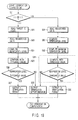
- a verification process is done for only a facial image obtained from a camera corresponding to the registered camera number. More specifically, as shown in, e.g., FIG. 16, a person to be verified inputs his or her own ID code via a keyboard, card, or the like, and the dictionary 7 is searched for the camera number and feature pattern registered in correspondence with that ID code (S42).
- a camera corresponding to the camera number retrieved from the dictionary 7 is selected (S43), and a facial image input by the selected camera undergoes the aforementioned image process to extract a feature pattern (S1 to S5).
- the extracted feature pattern is verified with the feature pattern retrieved from the dictionary 7 to determine if the person to be verified is the person himself or herself (S11, S12).
- two cameras are used.
- three or more cameras may be used.
- only one camera is selected, but when three or more cameras are used, two or more cameras may be selected.
- a required number of cameras are set in advance.
- a camera moving mechanism is arranged, and moves a single camera to a predetermined position so as to execute the aforementioned process.
- an image capture time is slightly prolonged, but only one camera is required, resulting in simple setting.
- FIG. 17 shows an example wherein one camera 1 is set. More specifically, as shown in FIG. 17, the camera 1 is fixed to a vertical guide rail 10 to be slidable vertically, and is moved by a camera moving mechanism (not shown) to a first position P1 (corresponding to the position of the camera 1-1 in FIG. 14) or a second position P2 (corresponding to the position of the camera 1-2 in FIG. 14). The camera 1 is set to be angled slightly upward.
- the basic arrangement of an image processing apparatus is substantially the same as that in FIG. 1 (first embodiment), except that the number of sets of cameras and capture boards is reduced to one, and a camera position controller 12 for controlling a camera moving mechanism 11 that moves the camera 1, and a communication board 13 for connecting the camera position controller 12 to the system bus 3 are added, as shown in FIG. 18.
- the process executed by the processor 4 according to the eighth embodiment is basically the same as that in FIG. 4 (first embodiment), except for the contents of the verification computation process in step S11.
- the verification computation process in step 11 will be described in detail below with reference to the flow chart shown in FIG. 19.
- the operation varies depending on whether 1 : 1 or 1 : N verification is done (S21).
- 1 : 1 verification is a verification process executed when a person to be verified inputs his or her own ID code to designate registered data to be verified
- 1 : N verification is a verification process executed when a person to be verified does not input any ID code to select all registered data as data to be verified.
- the ID code input by the person to be verified is read (S22).
- Registered data (partial space) corresponding to the read ID code is read from the dictionary 7 (S23).
- a verification level between the spatial space of the registered data and an input partial space is computed to verify using, e.g., the partial space method (S24).
- the verification level is compared with a predetermined threshold value (S25, S26) to output a 1 : 1 verification result (S27).
- the maximum verification level may undergo a threshold value process like in step S31 bounded by the broken line in FIG. 19, it can be checked if the verification result is correct (S33). For example, if the verification level is too low, it is determined that no match is found.
- N verification is a verification process executed when a person to be verified does not input any ID code to select all registered data as data to be verified, and corresponds to the verification process in the first to sixth embodiments described above.
- only one camera is used, but two or more cameras may be used. Furthermore, only one camera is moved. However, when two or more cameras are used, these cameras may be moved.
- a camera of a normal visible wavelength range is used.
- an infrared ray camera of an infrared range may be used, or a rangefinder that can obtain distance information (depth information) may be used.
- image input devices of different types may be mixed.
- an image processing apparatus and method which can reduce the load on the user upon registration and verification, can greatly improve verification performance, and can minimize increases in complicated computation and processing cost without largely changing a pattern verification process algorithm from a single direction can be provided.
- the technique of prior art 1 independently processes images although it uses a plurality of cameras, and a function is limited to detection of the face direction.
- the techniques of prior arts 2 and 3 since the countenance of a person has three-dimensional shape information, two-dimensional facial image information captured from only one direction alone limits personal identification performance, and practical verification performance cannot become so high compared to fingerprint verification, retina and iris scans, and the like.
Abstract
Description
(V11, V12,..., Vnm-1, Vnm)
M1 >= K1, and M2 >= K2, and M3 >= K3
where K1, K2, and K3 are predetermined threshold values is satisfied.
(M1 + M2 + M3)/3
is finally determined to be a match.
camera 1-2: (V21,..., V2L2) (L2 dimension)
...
camera 1-n: (Vn1,..., VnLn) (Ln dimension)
are computed from the outputs of the cameras 1-1, 1-2,..., 1-n, these feature vectors are integrated by coupling in turn:
(V11,..., V1L1, V21,.., V2L2,..., Vn1,..., VnLn)
(L1+L2+...+Ln) dimension
time 1: (V11,..., V1L)
time 2: (V21,..., V2L)
...
time s: (Vs1,..., VsL)
are integrated on the time series to obtain an average vector described by:
(

M1 >= K1 or M2 >= K2
where K1 and K2 are predetermined threshold values is satisfied.
R >= T (T ≥ 2)
where R is the number of times Mi >+ Ki (i = 1, 2,..., n) holds, and Ki and T are predetermined threshold values is satisfied.
Claims (30)
- An image processing apparatus characterized by comprising:
image processing means (1-1, 1-2,..., 1-N, 2-1, 2-2,..., 2-N, 4) for sensing object images from different directions, extracting feature points from the sensed object images, and computing a feature pattern on the basis of the extracted feature points. - An apparatus according to claim 1, characterized by comprising:a plurality of image sensing means (1-1, 1-2,..., 1-N) for sensing object images from different directions; andnormalization means (4) for extracting feature points from the object images sensed by said plurality of image sensing means, setting a feature region on the basis of the extracted feature points, segmenting the set feature region into a plurality of regions, computing predetermined information in each segmented region, and computing a feature pattern on the basis of the computed predetermined information.
- An apparatus according to claim 1, characterized by comprising:a plurality of image sensing means (1-1, 1-2,..., 1-N) for sensing object images from different directions;normalization means (4) for extracting feature points from the object images sensed by said plurality of image sensing means, setting a feature region on the basis of the extracted feature points, segmenting the set feature region into a plurality of regions, computing an average value of brightness levels in each segmented region, and computing a feature pattern on the basis of the computed average value;registration means (4, 7) for registering the feature pattern computed by said normalization means as a feature pattern associated with a predetermined object; andverification means (4, 7) for specifying an object associated with the object image by comparing the feature pattern computed by said normalization means with the feature pattern registered in said registration means.
- An apparatus according to claim 3, characterized in that said plurality of image sensing means line up vertically, and
said normalization means computes the feature pattern using one of a feature point group including central points of right and left pupils and central points of right and left nasal cavities of the object image, and a feature point group including central points of right and left pupils of the object image. - An apparatus according to claim 3, characterized in that said plurality of image sensing means line up horizontally, and
said normalization means computes the feature pattern using one of a feature point group including central points of right and left pupils and central points of right and left nasal cavities of the object image, a feature point group including central points of right and left pupils and a central point of a left nasal cavity of the object image, and a feature point group including central points of right and left pupils and a central point of a right nasal cavity of the object image. - An apparatus according to claim 3, characterized in that said plurality of image sensing means line up vertically and horizontally, and
said normalization means computes the feature pattern using one of a feature point group including central points of right and left pupils and central points of right and left nasal cavities of the object image, a feature point group including central points of right and left pupils and a central point of a left nasal cavity of the object image, a feature point group including central points of right and left pupils and a central point of a right nasal cavity of the object image, and a feature point group including central points of right and left pupils of the object image. - An apparatus according to claim 3, characterized in that said normalization means extracts feature vectors of different dimensions from respective object images sensed by said plurality of image sensing means, and arranges the extracted feature vectors of different dimensions in turn to integrate them as a multi-dimensional feature pattern.
- An apparatus according to claim 3, characterized in that said normalization means captures object images sensed by said plurality of image sensing means at predetermined time intervals, computes feature patterns of the object images of identical times, and arranges feature patterns of different times in turn to integrate them as a time-series feature pattern.
- An apparatus according to claim 1, characterized by comprising:image input means (1-1, 1-2,..., 1-N) for sensing an object image from different positions, and inputting a plurality of object images at different image sensing positions;feature extraction means (4) for extracting feature patterns that represent features of an object from the plurality of object images input by said image input means;verification means (4, 7) for verifying the plurality of feature patterns extracted by said feature extraction means with a reference feature pattern which is registered in advance; anddiscrimination means (4) for, when at least one of the plurality of feature patterns extracted by said feature extraction means matches the reference feature pattern which is registered in advance as a result of verification of said verification means, determining that an object associated with that object image is a person himself or herself.
- An apparatus according to claim 9, characterized in that said image input means has a plurality of image sensing means which are set in advance at a plurality of predetermined positions, and sense an object image from a plurality of different positions, and inputs a plurality of object images at different image sensing positions using said plurality of image sensing means.
- An apparatus according to claim 9, characterized in that said feature extraction means comprises:feature point detection means for detecting feature points of an object from the input object image;feature region setting means for setting a feature region on the basis of the feature points detected by said feature point detection means;region segmentation means for segmenting the feature region set by said feature region setting means into a plurality of regions; andfeature pattern extraction means for computing brightness average values in the regions segmented by said region segmentation means, and extracting a feature pattern which represents a feature of the object on the basis of the brightness average values.
- An apparatus according to claim 1,
characterized by comprising:image input means (1-1, 1-2,..., 1-N) for sensing an object image from different positions, and inputting a plurality of object images at different image sensing positions;input image determination means (4) for determining an image sensing position of an object image to be used from the plurality of object images input by said image input means upon registration of a feature pattern;first feature extraction means (4) for extracting a feature pattern which represents a feature of an object from the object image determined by said input image determination means;registration means (4, 7) for registering the feature pattern extracted by said first feature extraction means as a reference feature pattern associated with the object in correspondence with position information indicating the image sensing position of the corresponding object image;verification image selection means (4) for selecting an object image at an image sensing position, which corresponds to the position information registered together with the feature pattern of the object to be verified registered in said registration means, of the plurality of object images input by said image input means upon verification of a feature pattern;second feature extraction means (4) for extracting a feature pattern which represents a feature of the object from the object image selected by said verification image selection means; andverification means (4, 8) for specifying an object associated with the object image by verifying the feature pattern extracted by said second feature extraction means with the feature pattern of the object to be verified registered in said registration means. - An apparatus according to claim 1, characterized in that an object image is input at different image sensing positions by moving at least one image sensing means to a plurality of predetermined positions and sensing an object image at respective positions.
- An apparatus according to claim 1,
characterized by comprising:a plurality of image sensing means, respectively set in advance at a plurality of predetermined positions, for sensing an object image from a plurality of different positions;determination means for determining a position of the image sensing means to be used of said plurality of image sensing means upon registration of a feature pattern;first feature extraction means for extracting a feature pattern which represents a feature of an object from the object image obtained by the image sensing means determined by said determination means;registration means for registering the feature pattern extracted by said first feature extraction means as a reference feature pattern associated with the object in correspondence with position information indicating the position of the image sensing means determined by said determination means;selection means for selecting the image sensing means at a position, which corresponds to the position information registered together with the feature pattern of the object in said registration means, of said plurality of image sensing means upon verification of a feature pattern;second feature extraction means for extracting a feature pattern which represents a feature of the object from the object image obtained by the image sensing means selected by said selection means; andverification means for specifying an object associated with the object image by verifying the feature pattern extracted by said second feature extraction means with the feature pattern of the object registered in said registration means. - An apparatus according to claim 14, characterized in that each of said first and second feature extraction means comprises:feature point detection means for detecting feature points of an object from the input object image;feature region setting means for setting a feature region on the basis of the feature points detected by said feature point detection means;region segmentation means for segmenting the feature region set by said feature region setting means into a plurality of regions; andfeature pattern extraction means for computing brightness average values in the regions segmented by said region segmentation means, and extracting a feature pattern which represents a feature of the object on the basis of the brightness average values.
- An image processing method characterized by comprising:
the step (S0 - S5) of sensing object images from different directions, extracting feature points from the sensed object images, and computing a feature pattern on the basis of the extracted feature points. - A method according to claim 16, characterized by comprising:the first step (S0) of sensing object images from different directions; andthe second step (S1 - S5) of extracting feature points from the object images sensed in the first step, setting a feature region on the basis of the extracted feature points, segmenting the set feature region into a plurality of regions, computing predetermined information in each segmented region, and computing a feature pattern on the basis of the computed predetermined information.
- A method according to claim 16, characterized by comprising:the first step (S0) of sensing object images from different directions;the second step (S1 - S5) of extracting feature points from the object images sensed in the first step, setting a feature region on the basis of the extracted feature points, segmenting the set feature region into a plurality of regions, computing an average value of brightness levels in each segmented region, and computing a feature pattern on the basis of the computed average value;the third step (S7) of registering the feature pattern computed in the second step as a feature pattern associated with a predetermined object; andthe fourth step (S11, S12) of specifying an object associated with the object image by comparing the feature pattern computed in the second step with the feature pattern registered in the third step.
- A method according to claim 18, characterized in that the first step includes the step of sensing object images from different directions which line up vertically, and
the second step includes the step of computing the feature pattern using one of a feature point group including central points of right and left pupils and central points of right and left nasal cavities of the object image, and a feature point group including central points of right and left pupils of the object image. - A method according to claim 18, characterized in that the first step includes the step of sensing object images from different directions which line up horizontally, and
the second step includes the step of computing the feature pattern using one of a feature point group including central points of right and left pupils and central points of right and left nasal cavities of the object image, a feature point group including central points of right and left pupils and a central point of a left nasal cavity of the object image, and a feature point group including central points of right and left pupils and a central point of a right nasal cavity of the object image. - A method according to claim 18, characterized in that the first step includes the step of simultaneously sensing object images from directions different in vertical and horizontal directions, and
the second step includes the step of computing the feature pattern using one of a feature point group including central points of right and left pupils and central points of right and left nasal cavities of the object image, a feature point group including central points of right and left pupils and a central point of a left nasal cavity of the object image, a feature point group including central points of right and left pupils and a central point of a right nasal cavity of the object image, and a feature point group including central points of right and left pupils of the object image. - A method according to claim 18, characterized in that the second step includes the step of extracting feature vectors of different dimensions from respective object images sensed in the first step, and arranging the extracted feature vectors of different dimensions in turn to integrate them as a multi-dimensional feature pattern.
- A method according to claim 18, characterized in that the second step includes the step of capturing object images sensed in the first step at predetermined time intervals, computing feature pattern of the object images of identical times, and arranging feature patterns of different times in turn to integrate them as a time-series feature pattern.
- A method according to claim 16, characterized by comprising:the first step (S0) of sensing an object image from different positions, and inputting a plurality of object images at different image sensing positions;the second step (S1 - S5) of extracting feature patterns that represent features of an object from the plurality of object images input in the first step;the third step (S11) of verifying the plurality of feature patterns extracted in the second step with a reference feature pattern which is registered in advance; andthe fourth step (S12) of determining, when at least one of the plurality of feature patterns extracted in the second step matches the reference feature pattern which is registered in advance as a result of verification of the third step, that an object associated with that object image is a person himself or herself.
- A method according to claim 24, characterized in that the first step includes the step of inputting a plurality of object images at different image sensing positions using a plurality of image sensing means which are set in advance at a plurality of predetermined positions, and sense an object image from a plurality of different positions.
- A method according to claim 24, characterized in that the second step includes:the step of detecting feature points of an object from the input object image;the step of setting a feature region on the basis of the detected feature points;the step of segmenting the set feature region into a plurality of regions; andthe step of computing brightness average values in the segmented regions, and extracting a feature pattern which represents a feature of the object on the basis of the brightness average values.
- A method according to claim 16, characterized by comprising:the first step (S0) of sensing an object image from different positions, and inputting a plurality of object images at different image sensing positions;the second step (S41) of determining an image sensing position of an object image to be used from the plurality of object images input in the first step upon registration of a feature pattern;the third step (S1 - S5) of extracting a feature pattern which represents a feature of an object from the object image determined in the second step;the fourth step (S7 - S10) of registering the feature pattern extracted in the third step as a reference feature pattern associated with the object in correspondence with position information indicating the image sensing position of the corresponding object image;the fifth step (S42) of selecting an object image at an image sensing position, which corresponds to the position information registered together with the feature pattern of the object to be verified registered in the fourth step, of the plurality of object images input in the first step upon verification of a feature pattern;the sixth step (S1 - S5) of extracting a feature pattern which represents a feature of the object from the object image selected in the fifth step; andthe seventh step (S11, S12) of specifying an object associated with the object image by verifying the feature pattern extracted in the sixth step with the feature pattern of the object to be verified registered in the fourth step.
- A method according to claim 16, characterized in that an object image is input at different image sensing positions by moving at least one image sensing means to a plurality of predetermined positions and sensing an object image at respective positions.
- A method according to claim 16, characterized by comprising:the first step (S0) of inputting a plurality of object images at different image sensing positions using a plurality of image sensing means, respectively set in advance at a plurality of predetermined positions, for sensing an object image from a plurality of different positions;the second step (S41) of determining a position of the image sensing means to be used of said plurality of image sensing means upon registration of a feature pattern;the third step (S1 - S5) of extracting a feature pattern which represents a feature of an object from the object image obtained by the image sensing means determined in the second step;the fourth step (S7 - S10) of registering the feature pattern extracted in the third step as a reference feature pattern associated with the object in correspondence with position information indicating the position of the image sensing means determined in the second step;the fifth step (S43) of selecting the image sensing means at a position, which corresponds to the position information registered together with the feature pattern of the object in the fourth step, of said plurality of image sensing means upon verification of a feature pattern;the sixth step (S1 - S5) of extracting a feature pattern which represents a feature of the object from the object image obtained by the image sensing means selected in the fifth step; andthe seventh step (S11, S12) of specifying an object associated with the object image by verifying the feature pattern extracted in the sixth step with the feature pattern of the object registered in the fourth step.
- A method according to claim 29, characterized in that each of the third and sixth steps includes:the step of detecting feature points of an object from the input object image;the step of setting a feature region on the basis of the detected feature points;the step of segmenting the set feature region into a plurality of regions; andthe step of computing brightness average values in the segmented regions, and extracting a feature pattern which represents a feature of the object on the basis of the brightness average values.
Applications Claiming Priority (4)
| Application Number | Priority Date | Filing Date | Title |
|---|---|---|---|
| JP2000074489 | 2000-03-16 | ||
| JP2000074489 | 2000-03-16 | ||
| JP2000347043A JP2001331799A (en) | 2000-03-16 | 2000-11-14 | Image processor and image processing method |
| JP2000347043 | 2000-11-14 |
Publications (3)
| Publication Number | Publication Date |
|---|---|
| EP1134691A2 true EP1134691A2 (en) | 2001-09-19 |
| EP1134691A3 EP1134691A3 (en) | 2004-11-24 |
| EP1134691B1 EP1134691B1 (en) | 2008-04-30 |
Family
ID=26587705
Family Applications (1)
| Application Number | Title | Priority Date | Filing Date |
|---|---|---|---|
| EP01105113A Expired - Lifetime EP1134691B1 (en) | 2000-03-16 | 2001-03-02 | Image processing apparatus and method for extracting feature of faces |
Country Status (4)
| Country | Link |
|---|---|
| US (1) | US6873713B2 (en) |
| EP (1) | EP1134691B1 (en) |
| JP (1) | JP2001331799A (en) |
| DE (1) | DE60133788T2 (en) |
Cited By (10)
| Publication number | Priority date | Publication date | Assignee | Title |
|---|---|---|---|---|
| WO2004052691A1 (en) * | 2002-12-12 | 2004-06-24 | Daimlerchrysler Ag | Method and device for determining a three-dimension position of passengers of a motor car |
| WO2005008570A2 (en) * | 2003-05-27 | 2005-01-27 | Honeywell International Inc. | Face identification verification using frontal and side views |
| EP1605412A2 (en) * | 2004-03-12 | 2005-12-14 | Matsushita Electric Industrial Co., Ltd. | Multi-identification method and multi-identification apparatus |
| WO2005119601A1 (en) * | 2004-06-03 | 2005-12-15 | X-Pin.Com Gmbh | Device for the biometric control of installations |
| EP1696393A3 (en) * | 2005-02-28 | 2007-01-03 | Kabushiki Kaisha Toshiba | Face authenticating apparatus and entrance and exit management apparatus |
| WO2008063143A2 (en) * | 2006-11-23 | 2008-05-29 | Manas Yatirim Holding Anonim Sirketi | Mechanism for determination of viewer numbers at mass screening locations |
| EP2172872A2 (en) * | 2008-10-03 | 2010-04-07 | John Hyde | Extended image height camera |
| JP2012208597A (en) * | 2011-03-29 | 2012-10-25 | Canon Inc | Pattern identification device, pattern identification method and program |
| CN102915539A (en) * | 2012-09-26 | 2013-02-06 | 北京理工大学 | Method for extracting pose measurement feature points based on target feature modeling |
| CN108920639A (en) * | 2018-07-02 | 2018-11-30 | 北京百度网讯科技有限公司 | Context acquisition methods and equipment based on interactive voice |
Families Citing this family (62)
| Publication number | Priority date | Publication date | Assignee | Title |
|---|---|---|---|---|
| EP1136937B1 (en) * | 2000-03-22 | 2006-05-10 | Kabushiki Kaisha Toshiba | Facial image forming recognition apparatus and a pass control apparatus |
| GB0107780D0 (en) * | 2001-03-28 | 2001-05-16 | Hewlett Packard Co | Improvements relating to data delivery |
| US9400921B2 (en) * | 2001-05-09 | 2016-07-26 | Intel Corporation | Method and system using a data-driven model for monocular face tracking |
| JP4177598B2 (en) * | 2001-05-25 | 2008-11-05 | 株式会社東芝 | Face image recording apparatus, information management system, face image recording method, and information management method |
| CA2359269A1 (en) * | 2001-10-17 | 2003-04-17 | Biodentity Systems Corporation | Face imaging system for recordal and automated identity confirmation |
| KR100954640B1 (en) * | 2002-02-05 | 2010-04-27 | 파나소닉 주식회사 | Personal authentication method and device |
| JP3829729B2 (en) * | 2002-02-14 | 2006-10-04 | オムロン株式会社 | Personal authentication device |
| JP2003242486A (en) * | 2002-02-21 | 2003-08-29 | Japan Science & Technology Corp | Person attribute estimating device |
| JP3910893B2 (en) * | 2002-08-30 | 2007-04-25 | 富士通株式会社 | Image extraction method and authentication apparatus |
| US7499574B1 (en) * | 2002-11-07 | 2009-03-03 | Honda Motor Co., Ltd. | Video-based face recognition using probabilistic appearance manifolds |
| AU2003275724A1 (en) * | 2002-11-07 | 2004-06-07 | Matsushita Electric Industrial Co., Ltd. | Method for cerficating individual, iris registering device, system for certificating iris, and program for cerficating individual |
| JP3954484B2 (en) | 2002-12-12 | 2007-08-08 | 株式会社東芝 | Image processing apparatus and program |
| US7194110B2 (en) * | 2002-12-18 | 2007-03-20 | Intel Corporation | Method and apparatus for tracking features in a video sequence |
| JP4397212B2 (en) | 2003-02-05 | 2010-01-13 | 富士フイルム株式会社 | Identification device |
| JP3982817B2 (en) | 2003-03-07 | 2007-09-26 | 株式会社東芝 | Image processing apparatus and image processing method |
| US7596247B2 (en) * | 2003-11-14 | 2009-09-29 | Fujifilm Corporation | Method and apparatus for object recognition using probability models |
| WO2005059831A1 (en) * | 2003-12-11 | 2005-06-30 | Philips Intellectual Property & Standards Gmbh | Elastic image registration |
| JP4765008B2 (en) * | 2004-03-16 | 2011-09-07 | 国立大学法人静岡大学 | A method to detect head direction using pupil and nostril |
| US7693308B2 (en) * | 2004-03-24 | 2010-04-06 | Fujifilm Corporation | Authentication system, authentication method, machine readable medium storing thereon authentication program, certificate photograph taking apparatus, and certificate photograph taking method |
| US20060056667A1 (en) * | 2004-09-16 | 2006-03-16 | Waters Richard C | Identifying faces from multiple images acquired from widely separated viewpoints |
| US7469060B2 (en) * | 2004-11-12 | 2008-12-23 | Honeywell International Inc. | Infrared face detection and recognition system |
| US20060165264A1 (en) * | 2005-01-26 | 2006-07-27 | Hirofumi Saitoh | Method and apparatus for acquiring images, and verification method and verification apparatus |
| JP4696778B2 (en) * | 2005-08-23 | 2011-06-08 | コニカミノルタホールディングス株式会社 | Authentication apparatus, authentication method, and program |
| JP2007101573A (en) * | 2005-09-30 | 2007-04-19 | Fujifilm Corp | Print order receiving device |
| WO2007099834A1 (en) * | 2006-03-01 | 2007-09-07 | Nec Corporation | Face authentication device, face authentication method, and program |
| US9042606B2 (en) * | 2006-06-16 | 2015-05-26 | Board Of Regents Of The Nevada System Of Higher Education | Hand-based biometric analysis |
| JP4862518B2 (en) * | 2006-06-29 | 2012-01-25 | パナソニック株式会社 | Face registration device, face authentication device, and face registration method |
| US7925049B2 (en) * | 2006-08-15 | 2011-04-12 | Sri International | Stereo-based visual odometry method and system |
| JP2008310463A (en) * | 2007-06-13 | 2008-12-25 | Panasonic Corp | Biological authentication device |
| US8315441B2 (en) * | 2007-06-29 | 2012-11-20 | Nec Corporation | Masquerade detection system, masquerade detection method and masquerade detection program |
| JP4544282B2 (en) | 2007-09-14 | 2010-09-15 | ソニー株式会社 | Data processing apparatus, data processing method, and program |
| JP5169139B2 (en) * | 2007-10-25 | 2013-03-27 | 株式会社ニコン | Camera and image recording program |
| JP4541427B2 (en) * | 2008-03-25 | 2010-09-08 | 富士通株式会社 | Biometric authentication device, biometric information registration device, and biometric authentication method |
| TWI405145B (en) * | 2008-11-20 | 2013-08-11 | Ind Tech Res Inst | Pixel region-based image segmentation method, system and machine-readable storage medium |
| US8749347B1 (en) * | 2009-01-29 | 2014-06-10 | Bank Of America Corporation | Authorized custodian verification |
| US8502644B1 (en) | 2009-01-29 | 2013-08-06 | Bank Of American Corporation | Physical item security: tracking device activation |
| US8325981B2 (en) * | 2009-04-21 | 2012-12-04 | Nec Soft, Ltd. | Human tracking apparatus, human tracking method, and human tracking processing program |
| US8655084B2 (en) * | 2009-06-23 | 2014-02-18 | Board Of Regents Of The Nevada System Of Higher Education, On Behalf Of The University Of Nevada, Reno | Hand-based gender classification |
| US8384514B2 (en) * | 2009-08-07 | 2013-02-26 | At&T Intellectual Property I, L.P. | Enhanced biometric authentication |
| KR101083367B1 (en) * | 2010-01-26 | 2011-11-14 | 한남대학교 산학협력단 | Method and apparatus for user authentication using image |
| TWI410893B (en) * | 2010-11-22 | 2013-10-01 | Univ Chang Gung | Image aligning system and method thereof |
| JP5564414B2 (en) * | 2010-12-22 | 2014-07-30 | 日立オムロンターミナルソリューションズ株式会社 | Biometric authentication system and biometric authentication method |
| JP5720380B2 (en) * | 2011-04-01 | 2015-05-20 | 日本電気株式会社 | Object detection method, object detection apparatus, and object detection program |
| US9013489B2 (en) * | 2011-06-06 | 2015-04-21 | Microsoft Technology Licensing, Llc | Generation of avatar reflecting player appearance |
| KR20130119759A (en) * | 2012-04-24 | 2013-11-01 | 삼성전자주식회사 | Method and apparatus for recognizing three dimensional object |
| FR2997211B1 (en) * | 2012-10-18 | 2021-01-01 | Morpho | PROCESS FOR AUTHENTICATION OF AN IMAGE CAPTURE OF A THREE-DIMENSIONAL ENTITY |
| TWI508057B (en) * | 2013-07-15 | 2015-11-11 | Chunghwa Picture Tubes Ltd | Speech recognition system and method |
| JP6448223B2 (en) * | 2014-06-12 | 2019-01-09 | キヤノン株式会社 | Image recognition system, image recognition apparatus, image recognition method, and computer program |
| US9986289B2 (en) | 2015-03-02 | 2018-05-29 | The Nielsen Company (Us), Llc | Methods and apparatus to count people |
| WO2017064709A1 (en) * | 2015-10-15 | 2017-04-20 | P.C.O.A.Devices Ltd | Image recognition-based dosage form dispensers |
| CN106874921B (en) * | 2015-12-11 | 2020-12-04 | 清华大学 | Image classification method and device |
| US10606814B2 (en) | 2017-01-18 | 2020-03-31 | Microsoft Technology Licensing, Llc | Computer-aided tracking of physical entities |
| US10637814B2 (en) | 2017-01-18 | 2020-04-28 | Microsoft Technology Licensing, Llc | Communication routing based on physical status |
| US10679669B2 (en) | 2017-01-18 | 2020-06-09 | Microsoft Technology Licensing, Llc | Automatic narration of signal segment |
| US10437884B2 (en) | 2017-01-18 | 2019-10-08 | Microsoft Technology Licensing, Llc | Navigation of computer-navigable physical feature graph |
| US10635981B2 (en) | 2017-01-18 | 2020-04-28 | Microsoft Technology Licensing, Llc | Automated movement orchestration |
| US10482900B2 (en) | 2017-01-18 | 2019-11-19 | Microsoft Technology Licensing, Llc | Organization of signal segments supporting sensed features |
| US11094212B2 (en) * | 2017-01-18 | 2021-08-17 | Microsoft Technology Licensing, Llc | Sharing signal segments of physical graph |
| AU2017272325A1 (en) * | 2017-12-08 | 2019-06-27 | Canon Kabushiki Kaisha | System and method of generating a composite frame |
| CN109087411A (en) * | 2018-06-04 | 2018-12-25 | 上海灵纽智能科技有限公司 | A kind of recognition of face lock based on distributed camera array |
| DE102018121254A1 (en) * | 2018-08-30 | 2020-03-05 | Bundesdruckerei Gmbh | Access control system for capturing a facial image of a person |
| JP2021170176A (en) * | 2020-04-14 | 2021-10-28 | 株式会社日立製作所 | Individual identification system and individual identification program |
Citations (2)
| Publication number | Priority date | Publication date | Assignee | Title |
|---|---|---|---|---|
| US4975969A (en) * | 1987-10-22 | 1990-12-04 | Peter Tal | Method and apparatus for uniquely identifying individuals by particular physical characteristics and security system utilizing the same |
| US5230025A (en) * | 1990-08-31 | 1993-07-20 | Digital Biometrics, Inc. | Method and apparatus for capturing skin print images |
Family Cites Families (4)
| Publication number | Priority date | Publication date | Assignee | Title |
|---|---|---|---|---|
| US4641349A (en) * | 1985-02-20 | 1987-02-03 | Leonard Flom | Iris recognition system |
| CN1045129C (en) * | 1993-03-29 | 1999-09-15 | 松下电器产业株式会社 | Apparatus for identifying person |
| US6119096A (en) * | 1997-07-31 | 2000-09-12 | Eyeticket Corporation | System and method for aircraft passenger check-in and boarding using iris recognition |
| JPH11196398A (en) | 1997-12-26 | 1999-07-21 | Sony Corp | Image processing unit |
-
2000
- 2000-11-14 JP JP2000347043A patent/JP2001331799A/en active Pending
-
2001
- 2001-03-02 DE DE60133788T patent/DE60133788T2/en not_active Expired - Fee Related
- 2001-03-02 EP EP01105113A patent/EP1134691B1/en not_active Expired - Lifetime
- 2001-03-16 US US09/808,939 patent/US6873713B2/en not_active Expired - Fee Related
Patent Citations (2)
| Publication number | Priority date | Publication date | Assignee | Title |
|---|---|---|---|---|
| US4975969A (en) * | 1987-10-22 | 1990-12-04 | Peter Tal | Method and apparatus for uniquely identifying individuals by particular physical characteristics and security system utilizing the same |
| US5230025A (en) * | 1990-08-31 | 1993-07-20 | Digital Biometrics, Inc. | Method and apparatus for capturing skin print images |
Non-Patent Citations (4)
| Title |
|---|
| MING XU ET AL: "Detecting head pose from stereo image sequence for active face recognition" AUTOMATIC FACE AND GESTURE RECOGNITION, 1998. PROCEEDINGS. THIRD IEEE INTERNATIONAL CONFERENCE ON NARA, JAPAN 14-16 APRIL 1998, LOS ALAMITOS, CA, USA,IEEE COMPUT. SOC, US, 14 April 1998 (1998-04-14), pages 82-87, XP010277648 ISBN: 0-8186-8344-9 * |
| PROC. INT. WORKSHOP ON AUTOMATIC FACE AND GESTURE RECOGNITION, 26 June 1995 (1995-06-26), - 28 June 1995 (1995-06-28) pages 47-52, XP002297247 * |
| YAMAGUCHI O ET AL: "Face recognition using temporal image sequence" AUTOMATIC FACE AND GESTURE RECOGNITION, 1998. PROCEEDINGS. THIRD IEEE INTERNATIONAL CONFERENCE ON NARA, JAPAN 14-16 APRIL 1998, LOS ALAMITOS, CA, USA,IEEE COMPUT. SOC, US, 14 April 1998 (1998-04-14), pages 318-323, XP010277627 ISBN: 0-8186-8344-9 * |
| YASUMOTO M ET AL: "Face direction estimation and face recognition using multiple cameras for communication in a virtual environment" PROC. 3RD INT. CONF. ON ADVANCES IN MULTIMODAL INTERFACES, vol. 1, 22 October 2000 (2000-10-22), pages 295-300, XP010569634 BEIJING, CHINA * |
Cited By (15)
| Publication number | Priority date | Publication date | Assignee | Title |
|---|---|---|---|---|
| WO2004052691A1 (en) * | 2002-12-12 | 2004-06-24 | Daimlerchrysler Ag | Method and device for determining a three-dimension position of passengers of a motor car |
| US7421097B2 (en) | 2003-05-27 | 2008-09-02 | Honeywell International Inc. | Face identification verification using 3 dimensional modeling |
| WO2005008570A2 (en) * | 2003-05-27 | 2005-01-27 | Honeywell International Inc. | Face identification verification using frontal and side views |
| WO2005008570A3 (en) * | 2003-05-27 | 2005-05-06 | Honeywell Int Inc | Face identification verification using frontal and side views |
| EP1605412A2 (en) * | 2004-03-12 | 2005-12-14 | Matsushita Electric Industrial Co., Ltd. | Multi-identification method and multi-identification apparatus |
| EP1605412A3 (en) * | 2004-03-12 | 2006-05-24 | Matsushita Electric Industrial Co., Ltd. | Multi-identification method and multi-identification apparatus |
| WO2005119601A1 (en) * | 2004-06-03 | 2005-12-15 | X-Pin.Com Gmbh | Device for the biometric control of installations |
| EP1696393A3 (en) * | 2005-02-28 | 2007-01-03 | Kabushiki Kaisha Toshiba | Face authenticating apparatus and entrance and exit management apparatus |
| WO2008063143A2 (en) * | 2006-11-23 | 2008-05-29 | Manas Yatirim Holding Anonim Sirketi | Mechanism for determination of viewer numbers at mass screening locations |
| WO2008063143A3 (en) * | 2006-11-23 | 2008-07-10 | Parana Vision Goruntu Isleme T | Mechanism for determination of viewer numbers at mass screening locations |
| EP2172872A2 (en) * | 2008-10-03 | 2010-04-07 | John Hyde | Extended image height camera |
| EP2172872A3 (en) * | 2008-10-03 | 2011-04-20 | John Hyde | Extended image height camera |
| JP2012208597A (en) * | 2011-03-29 | 2012-10-25 | Canon Inc | Pattern identification device, pattern identification method and program |
| CN102915539A (en) * | 2012-09-26 | 2013-02-06 | 北京理工大学 | Method for extracting pose measurement feature points based on target feature modeling |
| CN108920639A (en) * | 2018-07-02 | 2018-11-30 | 北京百度网讯科技有限公司 | Context acquisition methods and equipment based on interactive voice |
Also Published As
| Publication number | Publication date |
|---|---|
| EP1134691A3 (en) | 2004-11-24 |
| EP1134691B1 (en) | 2008-04-30 |
| DE60133788T2 (en) | 2009-06-25 |
| US20030206645A1 (en) | 2003-11-06 |
| JP2001331799A (en) | 2001-11-30 |
| DE60133788D1 (en) | 2008-06-12 |
| US6873713B2 (en) | 2005-03-29 |
Similar Documents
| Publication | Publication Date | Title |
|---|---|---|
| EP1134691B1 (en) | Image processing apparatus and method for extracting feature of faces | |
| Huang et al. | Face detection and precise eyes location | |
| KR100456619B1 (en) | A system for registering and authenticating human face using support vector machines and method thereof | |
| US8515136B2 (en) | Image processing device, image device, image processing method | |
| Burge et al. | Ear biometrics | |
| KR100918286B1 (en) | Living body guidance control method for a biometrics authentication device, and biometrics authentication device | |
| JP3469031B2 (en) | Face image registration apparatus and method | |
| JP2000259814A (en) | Image processor and method therefor | |
| JP4351982B2 (en) | Personal authentication method, apparatus and program | |
| JP2004118627A (en) | Figure identification device and method | |
| KR20050025927A (en) | The pupil detection method and shape descriptor extraction method for a iris recognition, iris feature extraction apparatus and method, and iris recognition system and method using its | |
| KR101626837B1 (en) | Method and apparatus for convergence biometric authentication based on finger joint and finger vein | |
| JP2003178306A (en) | Personal identification device and personal identification method | |
| KR101640014B1 (en) | Iris recognition apparatus for detecting false face image | |
| JP2002183734A (en) | Face authentication device and face authentication method | |
| JP4521086B2 (en) | Face image recognition apparatus and face image recognition method | |
| JP5730044B2 (en) | Face image authentication device | |
| KR20020022295A (en) | Device And Method For Face Recognition Using 3 Dimensional Shape Information | |
| Burge et al. | Using ear biometrics for passive identification | |
| JP5796523B2 (en) | Biological information acquisition apparatus, biological information acquisition method, and biological information acquisition control program | |
| JP2690132B2 (en) | Personal verification method and device | |
| KR102089618B1 (en) | Method and system for collecting means of publictransportation fares using bi0-information | |
| JP2001331804A (en) | Device and method for detecting image area | |
| KR101965749B1 (en) | Camera based contactless fingerprint reader | |
| CN113128258B (en) | Living body detection method, living body detection device, electronic apparatus, and storage medium |
Legal Events
| Date | Code | Title | Description |
|---|---|---|---|
| PUAI | Public reference made under article 153(3) epc to a published international application that has entered the european phase |
Free format text: ORIGINAL CODE: 0009012 |
|
| 17P | Request for examination filed |
Effective date: 20010302 |
|
| AK | Designated contracting states |
Kind code of ref document: A2 Designated state(s): AT BE CH CY DE DK ES FI FR GB GR IE IT LI LU MC NL PT SE TR |
|
| AX | Request for extension of the european patent |
Free format text: AL;LT;LV;MK;RO;SI |
|
| PUAL | Search report despatched |
Free format text: ORIGINAL CODE: 0009013 |
|
| AK | Designated contracting states |
Kind code of ref document: A3 Designated state(s): AT BE CH CY DE DK ES FI FR GB GR IE IT LI LU MC NL PT SE TR |
|
| AX | Request for extension of the european patent |
Extension state: AL LT LV MK RO SI |
|
| 17Q | First examination report despatched |
Effective date: 20050603 |
|
| AKX | Designation fees paid |
Designated state(s): DE FR GB IT |
|
| 17Q | First examination report despatched |
Effective date: 20050603 |
|
| GRAP | Despatch of communication of intention to grant a patent |
Free format text: ORIGINAL CODE: EPIDOSNIGR1 |
|
| RTI1 | Title (correction) |
Free format text: IMAGE PROCESSING APPARATUS AND METHOD FOR EXTRACTING FEATURE OF FACES |
|
| GRAS | Grant fee paid |
Free format text: ORIGINAL CODE: EPIDOSNIGR3 |
|
| GRAA | (expected) grant |
Free format text: ORIGINAL CODE: 0009210 |
|
| AK | Designated contracting states |
Kind code of ref document: B1 Designated state(s): DE FR GB IT |
|
| REG | Reference to a national code |
Ref country code: GB Ref legal event code: FG4D |
|
| REF | Corresponds to: |
Ref document number: 60133788 Country of ref document: DE Date of ref document: 20080612 Kind code of ref document: P |
|
| ET | Fr: translation filed | ||
| PLBE | No opposition filed within time limit |
Free format text: ORIGINAL CODE: 0009261 |
|
| STAA | Information on the status of an ep patent application or granted ep patent |
Free format text: STATUS: NO OPPOSITION FILED WITHIN TIME LIMIT |
|
| 26N | No opposition filed |
Effective date: 20090202 |
|
| PG25 | Lapsed in a contracting state [announced via postgrant information from national office to epo] |
Ref country code: IT Free format text: LAPSE BECAUSE OF FAILURE TO SUBMIT A TRANSLATION OF THE DESCRIPTION OR TO PAY THE FEE WITHIN THE PRESCRIBED TIME-LIMIT Effective date: 20080430 |
|
| GBPC | Gb: european patent ceased through non-payment of renewal fee |
Effective date: 20090302 |
|
| REG | Reference to a national code |
Ref country code: FR Ref legal event code: ST Effective date: 20091130 |
|
| PG25 | Lapsed in a contracting state [announced via postgrant information from national office to epo] |
Ref country code: DE Free format text: LAPSE BECAUSE OF NON-PAYMENT OF DUE FEES Effective date: 20091001 |
|
| PG25 | Lapsed in a contracting state [announced via postgrant information from national office to epo] |
Ref country code: GB Free format text: LAPSE BECAUSE OF NON-PAYMENT OF DUE FEES Effective date: 20090302 Ref country code: FR Free format text: LAPSE BECAUSE OF NON-PAYMENT OF DUE FEES Effective date: 20091123 |